WO2023032051A1 - 照明制御装置、照明制御方法、記録媒体、及び、撮像システム - Google Patents
照明制御装置、照明制御方法、記録媒体、及び、撮像システム Download PDFInfo
- Publication number
- WO2023032051A1 WO2023032051A1 PCT/JP2021/032008 JP2021032008W WO2023032051A1 WO 2023032051 A1 WO2023032051 A1 WO 2023032051A1 JP 2021032008 W JP2021032008 W JP 2021032008W WO 2023032051 A1 WO2023032051 A1 WO 2023032051A1
- Authority
- WO
- WIPO (PCT)
- Prior art keywords
- illumination
- iris
- lighting
- eye
- area
- Prior art date
Links
- 238000005286 illumination Methods 0.000 title claims abstract description 841
- 238000003384 imaging method Methods 0.000 title claims description 256
- 238000000034 method Methods 0.000 title claims description 81
- 238000001514 detection method Methods 0.000 claims abstract description 8
- 230000003287 optical effect Effects 0.000 claims description 35
- 238000004590 computer program Methods 0.000 claims description 10
- 230000008859 change Effects 0.000 description 39
- 238000010586 diagram Methods 0.000 description 27
- 238000010191 image analysis Methods 0.000 description 26
- 208000016339 iris pattern Diseases 0.000 description 19
- 238000004891 communication Methods 0.000 description 17
- 238000012545 processing Methods 0.000 description 15
- 239000000284 extract Substances 0.000 description 9
- 230000000052 comparative effect Effects 0.000 description 8
- 230000000694 effects Effects 0.000 description 8
- 230000008569 process Effects 0.000 description 8
- 230000007423 decrease Effects 0.000 description 7
- 230000004424 eye movement Effects 0.000 description 6
- 210000000744 eyelid Anatomy 0.000 description 6
- 239000011521 glass Substances 0.000 description 5
- 230000002194 synthesizing effect Effects 0.000 description 4
- 239000000470 constituent Substances 0.000 description 3
- 230000006870 function Effects 0.000 description 3
- 241001465754 Metazoa Species 0.000 description 2
- 230000006866 deterioration Effects 0.000 description 2
- 230000001815 facial effect Effects 0.000 description 2
- 241000251468 Actinopterygii Species 0.000 description 1
- 241000269350 Anura Species 0.000 description 1
- 241000271566 Aves Species 0.000 description 1
- 241000282472 Canis lupus familiaris Species 0.000 description 1
- 241000252229 Carassius auratus Species 0.000 description 1
- 241000282326 Felis catus Species 0.000 description 1
- 241000270322 Lepidosauria Species 0.000 description 1
- 241000124008 Mammalia Species 0.000 description 1
- 241000287127 Passeridae Species 0.000 description 1
- 241000270295 Serpentes Species 0.000 description 1
- 230000002411 adverse Effects 0.000 description 1
- 238000004458 analytical method Methods 0.000 description 1
- 238000013459 approach Methods 0.000 description 1
- 230000002238 attenuated effect Effects 0.000 description 1
- 230000004397 blinking Effects 0.000 description 1
- 210000004087 cornea Anatomy 0.000 description 1
- 230000003247 decreasing effect Effects 0.000 description 1
- 239000011159 matrix material Substances 0.000 description 1
- 238000012986 modification Methods 0.000 description 1
- 230000004048 modification Effects 0.000 description 1
- 230000000737 periodic effect Effects 0.000 description 1
- 210000001747 pupil Anatomy 0.000 description 1
- 230000009467 reduction Effects 0.000 description 1
- 230000001568 sexual effect Effects 0.000 description 1
- 239000007787 solid Substances 0.000 description 1
Images


Classifications
-
- G—PHYSICS
- G06—COMPUTING; CALCULATING OR COUNTING
- G06V—IMAGE OR VIDEO RECOGNITION OR UNDERSTANDING
- G06V40/00—Recognition of biometric, human-related or animal-related patterns in image or video data
- G06V40/10—Human or animal bodies, e.g. vehicle occupants or pedestrians; Body parts, e.g. hands
- G06V40/18—Eye characteristics, e.g. of the iris
- G06V40/197—Matching; Classification
-
- A—HUMAN NECESSITIES
- A61—MEDICAL OR VETERINARY SCIENCE; HYGIENE
- A61B—DIAGNOSIS; SURGERY; IDENTIFICATION
- A61B5/00—Measuring for diagnostic purposes; Identification of persons
- A61B5/117—Identification of persons
- A61B5/1171—Identification of persons based on the shapes or appearances of their bodies or parts thereof
-
- G—PHYSICS
- G03—PHOTOGRAPHY; CINEMATOGRAPHY; ANALOGOUS TECHNIQUES USING WAVES OTHER THAN OPTICAL WAVES; ELECTROGRAPHY; HOLOGRAPHY
- G03B—APPARATUS OR ARRANGEMENTS FOR TAKING PHOTOGRAPHS OR FOR PROJECTING OR VIEWING THEM; APPARATUS OR ARRANGEMENTS EMPLOYING ANALOGOUS TECHNIQUES USING WAVES OTHER THAN OPTICAL WAVES; ACCESSORIES THEREFOR
- G03B15/00—Special procedures for taking photographs; Apparatus therefor
- G03B15/02—Illuminating scene
-
- G—PHYSICS
- G06—COMPUTING; CALCULATING OR COUNTING
- G06F—ELECTRIC DIGITAL DATA PROCESSING
- G06F3/00—Input arrangements for transferring data to be processed into a form capable of being handled by the computer; Output arrangements for transferring data from processing unit to output unit, e.g. interface arrangements
- G06F3/01—Input arrangements or combined input and output arrangements for interaction between user and computer
- G06F3/011—Arrangements for interaction with the human body, e.g. for user immersion in virtual reality
- G06F3/013—Eye tracking input arrangements
-
- G—PHYSICS
- G06—COMPUTING; CALCULATING OR COUNTING
- G06T—IMAGE DATA PROCESSING OR GENERATION, IN GENERAL
- G06T1/00—General purpose image data processing
-
- G—PHYSICS
- G06—COMPUTING; CALCULATING OR COUNTING
- G06T—IMAGE DATA PROCESSING OR GENERATION, IN GENERAL
- G06T7/00—Image analysis
- G06T7/20—Analysis of motion
-
- G—PHYSICS
- G06—COMPUTING; CALCULATING OR COUNTING
- G06V—IMAGE OR VIDEO RECOGNITION OR UNDERSTANDING
- G06V10/00—Arrangements for image or video recognition or understanding
- G06V10/10—Image acquisition
- G06V10/12—Details of acquisition arrangements; Constructional details thereof
- G06V10/14—Optical characteristics of the device performing the acquisition or on the illumination arrangements
- G06V10/141—Control of illumination
-
- G—PHYSICS
- G06—COMPUTING; CALCULATING OR COUNTING
- G06V—IMAGE OR VIDEO RECOGNITION OR UNDERSTANDING
- G06V40/00—Recognition of biometric, human-related or animal-related patterns in image or video data
- G06V40/10—Human or animal bodies, e.g. vehicle occupants or pedestrians; Body parts, e.g. hands
- G06V40/18—Eye characteristics, e.g. of the iris
- G06V40/19—Sensors therefor
-
- G—PHYSICS
- G06—COMPUTING; CALCULATING OR COUNTING
- G06V—IMAGE OR VIDEO RECOGNITION OR UNDERSTANDING
- G06V40/00—Recognition of biometric, human-related or animal-related patterns in image or video data
- G06V40/10—Human or animal bodies, e.g. vehicle occupants or pedestrians; Body parts, e.g. hands
- G06V40/18—Eye characteristics, e.g. of the iris
- G06V40/193—Preprocessing; Feature extraction
-
- G—PHYSICS
- G06—COMPUTING; CALCULATING OR COUNTING
- G06V—IMAGE OR VIDEO RECOGNITION OR UNDERSTANDING
- G06V2201/00—Indexing scheme relating to image or video recognition or understanding
- G06V2201/07—Target detection
Definitions
- This disclosure relates to technical fields of lighting control devices, lighting control methods, recording media, and imaging systems that can be used in, for example, an authentication system that authenticates an object using the iris of the object.
- Patent Document 1 describes an example of an authentication system capable of authenticating a target using an image generated by imaging the target's eye (especially the iris).
- Patent Documents 2 to 8 are cited as prior art documents related to this disclosure.
- the object of this disclosure is to provide a lighting control device, a lighting control method, a recording medium, and an imaging system that aim to improve the techniques described in prior art documents.
- an iris region corresponding to the iris of the eye and the illumination light are included in an eye image generated by capturing an image of the eye of a subject illuminated by illumination light from the illumination device. and illumination control means for controlling the illumination device based on the state of overlap between the iris area and the reflection area.
- One aspect of the illumination control method includes: in an eye image generated by capturing at least an image of an eye of a subject illuminated by illumination light from an illumination device, an iris region corresponding to the iris of the eye; detecting a reflection area corresponding to a reflected image of light; and controlling the illumination device based on a state of overlap between the iris area and the reflection area.
- a computer stores an iris region corresponding to the iris of the eye in an eye image generated by imaging at least the eye of a subject illuminated by illumination light from an illumination device; executing an illumination control method including detecting a reflection area corresponding to a reflected image of the illumination light, and controlling the illumination device based on a state of overlap between the iris area and the reflection area.
- an illumination control method including detecting a reflection area corresponding to a reflected image of the illumination light, and controlling the illumination device based on a state of overlap between the iris area and the reflection area.
- an imaging system includes a right illumination device that emits right illumination light capable of illuminating at least the right eye of a subject, a left illumination device that emits left illumination light capable of illuminating at least the left eye of the subject, and the right illumination device.
- an imaging device for imaging the right eye illuminated with light and the left eye illuminated with the left illumination light wherein the right illumination device is arranged on the left side of the imaging device facing the imaging device;
- the lighting device is arranged on the right side of the imaging device facing the imaging device, and the optical axis of the right lighting device and the optical axis of the left lighting device are positioned at the timing when the imaging device images the right eye and the left eye. intersect between the imaging device and the object.
- FIG. 1 is a block diagram showing the configuration of the lighting control device according to the first embodiment.
- FIG. 2 is a block diagram showing the configuration of an imaging system according to the second embodiment.
- FIG. 3 is a block diagram showing the overall configuration of an authentication system according to the third embodiment.
- FIG. 4 is a block diagram showing the configuration of an authentication device according to the third embodiment.
- FIG. 5 is a flow chart showing the flow of the authentication operation performed by the authentication device according to the third embodiment.
- FIG. 6 shows an example of iris and reflection areas detected in an eye image.
- FIG. 7 shows an example of iris and reflection areas detected in an eye image.
- FIGS. 8(a) and 8(b) respectively show an example of an iris region and a reflection region detected in an eye image.
- FIG. 9 is a block diagram showing the configuration of an authentication device according to the fourth embodiment.
- FIG. 10 is a flow chart showing the flow of authentication operation performed by the authentication device in the fourth embodiment.
- FIG. 11 is a block diagram showing the configuration of an authentication device according to the fifth embodiment.
- FIG. 12 is a flow chart showing the flow of authentication operation performed by the authentication device according to the fifth embodiment.
- FIGS. 13(a) and 13(b) respectively show an example of an iris region and a reflection region detected in an eye image.
- FIGS. 14(a) and 14(b) respectively show an example of an iris region and a reflection region detected in an eye image.
- FIG. 15 schematically shows how a plurality of eye images are synthesized.
- FIG. 15 schematically shows how a plurality of eye images are synthesized.
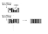
- FIG. 16 schematically shows how a plurality of feature quantities extracted from a plurality of eye images are combined.
- FIG. 17 is a block diagram showing the overall configuration of an authentication system according to the sixth embodiment.
- FIG. 18 shows the positional relationship of multiple lighting devices in the sixth embodiment.
- FIG. 19 is a flow chart showing the flow of the authentication operation performed by the authentication device according to the sixth embodiment.
- FIG. 20 shows the positional relationship between the lighting ranges of a plurality of lighting devices and the eyes of a target person.
- FIG. 21 is a block diagram showing the overall configuration of an authentication system according to the seventh embodiment.
- FIG. 22 is a flow chart showing the flow of the authentication operation performed by the authentication device in the seventh embodiment.
- FIG. 23 is a block diagram showing the overall configuration of an authentication system according to the eighth embodiment.
- FIG. 24 is a block diagram showing configurations of a right lighting device, a left lighting device, an imaging device, and an imaging system according to the eighth embodiment.
- FIG. 25 is a block diagram showing the configuration of an authentication device according to the eighth embodiment.
- FIG. 26 is a flow chart showing the flow of authentication operation performed by the authentication device in the eighth embodiment.
- FIG. 27 is a block diagram showing configurations of a right lighting device, a left lighting device, an imaging device, and an imaging system in a comparative example.
- FIGS. 28(a) and 28(b) shows an example of an eye image.
- FIG. 29 is a block diagram showing the configuration of an authentication device according to the ninth embodiment.
- FIG. 30 is a flow chart showing the flow of the authentication operation performed by the authentication device in the ninth embodiment.
- FIG. 31 is a block diagram showing the configuration of an authentication device according to the tenth embodiment.
- FIG. 32 is a flow chart showing the flow of authentication operation performed by the authentication device in the tenth embodiment.
- FIG. 1 is a block diagram showing the configuration of a lighting control device 1000 according to the first embodiment.
- the lighting control device 1000 includes a detection unit 1001 and a lighting control unit 1002.
- the detection unit 1001 detects an iris region corresponding to the iris of the eye and a reflected image of the illumination light in an eye image 1004 generated by capturing an image of at least the eye of the object illuminated by the illumination light from the illumination device 1003 . and a reflection area corresponding to .
- the illumination control unit 1002 controls the illumination device 1003 based on the overlapping state of the iris area and the reflection area.
- the lighting control device 1000 of the first embodiment can control the lighting device 1003 based on the overlapping state of the iris region and the reflection region. Therefore, the lighting control apparatus 1000 can reduce the influence of the overlapping of the iris area and the reflection area in the eye image 1004 on authentication accuracy. Therefore, an authentication system using such an illumination control device 1000 can reduce the influence of overlap between the iris region and the reflection region in the eye image 1004 when authenticating an object using the iris of the object. That is, the authentication system using the lighting control device 1000 can authenticate the target using the iris of the target with higher accuracy than the authentication system not using the lighting control device 1000 .
- FIG. 2 is a block diagram showing the configuration of an imaging system 2000 according to the second embodiment.
- the imaging system 2000 includes a right lighting device 2001, a left lighting device 2002, and an imaging device 2003.
- the right illumination device 2001 emits right illumination light 2004 capable of illuminating at least the right eye of a target (a person in the example shown in FIG. 2).
- Left illumination device 2002 emits left illumination light 2005 capable of illuminating at least the left eye of the subject.
- the imaging device 2003 images the right eye illuminated by the right illumination light 2004 and the left eye illuminated by the left illumination light 2005 .
- the right illumination device 2001 is arranged on the left side of the imaging device 2003 (the ⁇ X side in the example shown in FIG. 2) of the imaging device 2003 .
- the left lighting device 2002 is arranged on the right side of the imaging device 2003 (the +X side in the example shown in FIG. 2) when facing the imaging device 2003 .
- the optical axis 2006 of the right lighting device 2001 (for example, the optical axis of the optical system such as the lens provided in the right lighting device 2001) and the optical axis 2007 of the left lighting device 2002 (For example, the optical axis of an optical system such as a lens included in the left illumination device 2002) intersects between the imaging device 2003 and the object.
- the right lighting device 2001 may be arranged in the imaging device 2003 .
- the right lighting device 2001 may be arranged at a position different from that of the imaging device 2003 .
- the right lighting device 2001 may be integrated with the imaging device 2003 .
- the right lighting device 2001 may be arranged independently from the imaging device 2003 .
- the left lighting device 2002 may be arranged in the imaging device 2003 .
- the left illumination device 2002 may be arranged at a position different from that of the imaging device 2003 .
- the left lighting device 2002 may be integrated with the imaging device 2003 .
- the left lighting device 2002 may be arranged independently from the imaging device 2003 .
- a gate device through which an object can pass is arranged, at least one of the right lighting device 2001 and the left lighting device 2002 may be arranged at the gate device.
- the imaging device 2003 may capture an image of the object passing through the gate device.
- the iris region corresponding to the iris of the eye (for example, at least one of the right eye and the left eye) in the eye image generated by the imaging device is illuminated with illumination light (for example, the right eye).
- illumination light for example, the right eye
- At least one of illumination light, left illumination light, and other illumination light may overlap.
- the possibility that the iris area and the reflection area overlap increases as the angle of incidence of the illumination light on the lens of the spectacles covering the eye decreases.
- the right lighting device 2001 is arranged on the left side of the imaging device 2003, and the optical axis 2006 of the right lighting device 2001 and the optical axis 2007 of the left lighting device 2002 are positioned between the imaging device 2003 and the object. intersect at As a result, the right illumination for the right lens of the spectacles covering the right eye is reduced compared to the case where the right illuminator 2001 is positioned to the right of the imaging device 2003 and/or the optical axes 2006 and 2007 do not intersect.
- the incident angle of light 2004 increases.
- the iris area corresponding to the iris of the right eye may overlap with the reflection area corresponding to the reflected image of the right illumination light. becomes lower.
- the left lighting device 2002 is arranged on the right side of the imaging device 2003, and the optical axis 2006 of the right lighting device 2001 and the optical axis 2007 of the left lighting device 2002 are aligned with the imaging device 2003. intersect between As a result, the left illumination for the left lens of the spectacles covering the left eye is reduced compared to the case where the left illuminator 2002 is positioned to the left of the imaging device 2003 and/or the optical axes 2006 and 2007 do not intersect.
- the incident angle of light 2005 increases.
- the iris area corresponding to the iris of the left eye may overlap with the reflection area corresponding to the reflected image of the left illumination light. becomes lower.
- the imaging system 2000 can reduce the influence of the overlapping of the iris area and the reflection area in the eye image on authentication accuracy. Therefore, an authentication system using such an imaging system 2000 can reduce the influence of overlap between the iris area and the reflection area in the eye image when authenticating the object using the iris of the object. In other words, the authentication system using the imaging system 2000 can authenticate the target using the iris of the target with higher accuracy than the authentication system not using the imaging system 2000 .
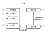
- FIG. 3 is a block diagram showing the overall configuration of an authentication system SYSa according to the third embodiment.
- the authentication system SYSa includes an imaging device 1 , a lighting device 2 and an authentication device 3 .
- the imaging device 1 is capable of imaging at least part of the target.
- An object may include, for example, a person.
- the target may include animals other than humans (for example, at least one of mammals such as dogs and cats, birds such as sparrows, reptiles such as snakes, amphibians such as frogs, and fish such as goldfish).
- Objects may include inanimate objects. Inanimate objects may include robots that resemble humans or animals. In the following description, an example in which the target is a person (hereinafter referred to as "target person”) will be described.
- the imaging device 1 can generate a person image IMG in which at least part of the target person is captured.
- the imaging device 1 captures an eye of the target person P (especially, the eye including the iris), thereby creating an eye image IMG_E in which the eye of the target person (especially the eye including the iris) is captured. , which can be generated as a person image IMG.
- the illumination device 2 can emit illumination light IL.
- the illumination device 2 illuminates the target person (in particular, the eyes) with the emitted illumination light IL when the imaging device 1 captures an image of the target person.
- the illumination device 2 can change the illumination mode of the illumination light IL for the eyes of the target person.
- the illumination device 2 includes a plurality of light emitting elements 21 each capable of emitting illumination light IL in order to change the illumination mode of the illumination light IL with respect to the eyes of the target person.
- the light-emitting element 21 is a specific example of a “light emitting portion” in the appendix described later.
- the illumination device 2 changes at least one of the number and position of the light emitting elements 21 that emit the illumination light IL, thereby changing the illumination mode of the illumination light IL with respect to the eyes of the target person.
- You may The illumination device 2 may change the illumination mode of the illumination light IL for the eyes of the target person by changing the angle (in other words, direction) at which the light emitting element 21 emits the illumination light IL.
- the illumination device 2 may change the illumination mode of the illumination light IL for the eyes of the target person by changing the intensity of the illumination light IL emitted by the light emitting element 21 .
- the illumination device 2 has the number of light emitting elements 21 that emit the illumination light IL, the positions of the light emitting elements 21 that emit the illumination light IL, the angles at which the light emitting elements 21 emit the illumination light IL, and the angles at which the light emitting elements 21 emit the illumination light IL. and at least one of the intensity of the illumination light IL emitted by the light emitting element 21 may be considered to change the state of the reflected image of the illumination light IL reflected in the eye image IMG_E.
- the authentication device 3 acquires the eye image IMG_E from the imaging device 1, and uses the eye image IMG_E to perform an authentication operation for authenticating the target person.
- the authentication device 3 uses the iris pattern of the target person's eyes reflected in the eye image IMG_E to perform an authentication operation for authenticating the target person. That is, the authentication device 3 performs an authentication operation related to iris authentication. Specifically, based on the iris pattern appearing in the obtained eye image IMG_E, the authentication device 3 determines that the target person appearing in the obtained eye image IMG_E is a pre-registered person (hereinafter referred to as “ (referred to as "registered person").
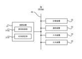
- FIG. 4 is a block diagram showing the configuration of the authentication device 3. As shown in FIG.
- the authentication device 3 includes an arithmetic device 31, a storage device 32, and a communication device 33. Furthermore, the authentication device 3 may comprise an input device 34 and an output device 35 . However, the authentication device 3 does not have to include at least one of the input device 34 and the output device 35 . Arithmetic device 31 , storage device 32 , communication device 33 , input device 34 , and output device 35 may be connected via data bus 36 .
- the arithmetic unit 31 is, for example, a CPU (Central Processing Unit), a GPU (Graphics Processing Unit), an FPGA (Field Programmable Gate Array), a DSP (Demand-Side Platform), and at least one of ASIC (Application Specific Integrated) including.
- Arithmetic device 31 reads a computer program.
- arithmetic device 31 may read a computer program stored in storage device 32 .
- the computing device 31 may read a computer program stored in a computer-readable non-temporary recording medium using a recording medium reading device (not shown) included in the authentication device 3 .
- the arithmetic device 31 may acquire (that is, download) a computer program from a device (not shown) arranged outside the authentication device 3 via the communication device 33 (or other communication device). or read). Arithmetic device 31 executes the read computer program. As a result, a logical functional block for executing the operation (for example, the authentication operation described above) that the authentication device 3 should perform is realized in the arithmetic device 31 .
- the computing device 31 can function as a controller for realizing logical functional blocks for executing the operation (in other words, processing) that the authentication device 3 should perform.
- FIG. 4 shows an example of logical functional blocks implemented within the computing device 31 to perform authentication operations.
- the arithmetic unit 31 includes an image analysis unit 311 as a specific example of the "detection means" in the appendix to be described later, and an illumination unit as a specific example of the "illumination control means” in the appendix to be described later.
- a control unit 312 and an iris authentication unit 313 are realized.
- the image analysis unit 311 analyzes the eye image IMG_E generated by the imaging device 1 . Specifically, the image analysis unit 311 detects an iris area IA (see FIG. 6 described later) corresponding to the iris of the target person in the eye image IMG_E. Furthermore, the image analysis unit 311 detects a reflection area RA (see FIG. 6 described later) corresponding to the reflection image of the illumination light IL in the eye image IMG_E.
- the illumination control unit 312 controls the illumination device 2 based on the analysis result of the eye image IMG_E by the image analysis unit 311 .
- the illumination control unit 312 controls the illumination device 2 based on the state of overlap between the iris area IA and the reflection area RA detected by the image analysis unit 311 .
- the iris authentication unit 313 authenticates the target person based on the eye image IMG_E.
- the storage device 32 can store desired data.
- the storage device 32 may temporarily store computer programs executed by the arithmetic device 31 .
- the storage device 32 may temporarily store data that is temporarily used by the arithmetic device 31 while the arithmetic device 31 is executing a computer program.
- the storage device 32 may store data that the authentication device 3 saves for a long time.
- the storage device 32 may include at least one of RAM (Random Access Memory), ROM (Read Only Memory), hard disk device, magneto-optical disk device, SSD (Solid State Drive), and disk array device. good. That is, the storage device 32 may include non-transitory recording media.
- the communication device 33 can communicate with devices external to the authentication device 3 via a communication network (not shown).
- the communication device 33 may be capable of receiving (that is, acquiring) the person image IMG (specifically, the eye image IMG_E) from the imaging device 1 .
- the communication device 33 may be capable of transmitting lighting control signals for controlling the lighting device 2 to the lighting device 2 .
- the input device 34 is a device that accepts input of information to the authentication device 3 from the outside of the authentication device 3 .
- the input device 34 may include an operating device (for example, at least one of a keyboard, a mouse and a touch panel) that can be operated by the operator of the authentication device 3 .
- the input device 34 may include a reading device capable of reading information recorded as data on a recording medium that can be externally attached to the authentication device 3 .
- the output device 35 is a device that outputs information to the outside of the authentication device 3 .
- the output device 35 may output information as an image. That is, the output device 35 may include a display device (so-called display) capable of displaying an image showing information to be output.
- the output device 35 may output information as audio.
- the output device 35 may include an audio device capable of outputting audio (so-called speaker).
- the output device 35 may output information on paper.
- the output device 35 may include a printing device (so-called printer) capable of printing desired information on paper. (3-3) Authentication Operation Performed by Authentication Device 3 Subsequently, the authentication operation performed by the authentication device 3 will be described with reference to FIG.
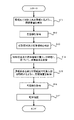
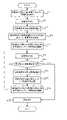
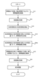
- FIG. 5 is a flow chart showing the flow of the authentication operation performed by the authentication device 3. As shown in FIG.
- the illumination control unit 312 controls the illumination device 2 so as to illuminate the eyes of the target person with the illumination light IL (step S11).
- the illumination control unit 312 may control the illumination device 2 based on the default illumination conditions so that the eyes of the target person are illuminated with the illumination light IL according to the default illumination conditions.
- an illumination condition that "all of the plurality of light emitting elements 21 included in the illumination device 2 emit illumination light IL" may be used as the default illumination condition.
- the lighting controller 312 may control the lighting device 2 such that all of the plurality of light emitting elements 21 included in the lighting device 2 emit the illumination light IL.
- the illumination control unit 312 causes some of the plurality of light emitting elements 21 included in the illumination device 2 to emit the illumination light IL and some of the plurality of light emitting elements 21 included in the illumination device 2 to The lighting device 2 may be controlled so as not to emit the illumination light IL.
- the imaging device 1 images the eyes of the target person. As a result, the imaging device 1 generates an eye image IMG_E.
- the image analysis unit 311 uses the communication device 33 to receive (that is, obtain) the eye image IMG_E from the imaging device 1 (step S12).
- the image analysis unit 311 detects the iris area IA corresponding to the iris of the target person and the reflection area RA corresponding to the reflected image of the illumination light IL in the eye image IMG_E acquired in step S12 (step S13 ).
- An example of the iris area IA and the reflection area RA detected in the eye image IMG_E is shown in FIG.
- the iris area IA is an annular (in other words, doughnut-shaped) area surrounded by the outer edge (that is, the outer contour) OE of the iris and the inner edge (that is, the inner contour) IE of the iris. It may include at least the region. Therefore, the image analysis unit 311 may detect the iris area IA by detecting feature points relating to the outer edge OE of the iris and feature points relating to the inner edge IE of the iris from the eye image IMG_E. Note that the outer edge of the pupil may be used as the inner edge IE of the iris. Also, as shown in FIG. 6, part of the iris may be hidden by the eyelid.
- the image analysis unit 311 detects the eyelid edge ER from the eye image IMG_E, and deletes the area hidden by the eyelid from the annular iris area IA based on the detected eyelid edge ER.
- the iris area IA may be an area surrounded by the outer edge OE of the iris, the inner edge IE of the iris, and the edge ER of the eyelid.
- the reflective area RA is an area in which a reflected image of the illumination light IL emitted by the light emitting element 21 is reflected.
- the characteristics of the reflective area RA are significantly different from those of the area of the eye image IMG_E excluding the reflective area RA. Therefore, the image analysis section 311 may detect the reflection area RA based on the characteristics of the eye image IMG_E.
- the luminance (that is, brightness) of the reflective area RA is higher than the luminance of the area of the eye image IMG_E excluding the reflective area RA. Therefore, the image analysis section 311 may detect the reflection area RA based on the brightness of the eye image IMG_E.
- the image analysis unit 311 may detect a set of pixels whose brightness exceeds a predetermined threshold as the reflective area RA. For example, the image analysis unit 311 may detect, as the reflective area RA, a set of pixels with higher brightness than surrounding pixels.
- the reflected image of the illumination light IL may include an image formed by the reflected light of the illumination light IL reflected by at least part of the eye of the target person.
- the reflected image of the illumination light IL may include an image formed by the reflected light of the illumination light IL reflected by at least one of the cornea and the eyelid.
- the reflected image of the illumination light IL may include an image formed by the reflected light of the illumination light IL reflected by at least part of the glasses worn by the target person.
- the reflected image of the illumination light IL may include an image formed by the reflected light of the illumination light IL reflected by at least part of the contact lens worn by the target person.
- the illumination device 2 since the illumination device 2 includes the plurality of light emitting elements 21 as described above, the eyes of the target person are illuminated by the plurality of illumination lights IL emitted from the plurality of light emitting elements 21, respectively.
- the eye image IMG_E may include a plurality of reflected images corresponding to the plurality of illumination lights IL. Therefore, the image analysis section 311 may detect a plurality of reflection areas RA respectively corresponding to a plurality of illumination lights IL.
- the plurality of light emitting elements 21 may each emit a plurality of illumination lights IL so that the sizes of the plurality of reflection areas RA are reduced.
- the plurality of light emitting elements 21 may each emit a plurality of illumination lights IL such that each reflection area RA forms a relatively small dot pattern.
- the light-emitting element 21 has a relatively small spot diameter of the illumination light IL on the irradiation surface (for example, the surface of the eye, eyeglasses, or contact lens) irradiated with the illumination light IL.
- Illumination light IL may be emitted as shown in FIG.
- the illumination control unit 312 then controls the illumination device 2 based on the iris area IA detected in step S13 and the reflection area RA detected in step S13 (from step S14 to step S15). Specifically, the illumination control section 312 controls the illumination device 2 based on the overlapping state of the iris area IA and the reflection area RA.
- the illumination control unit 312 determines illumination conditions that define the operating state of the illumination device 2 based on the state of overlap between the iris area IA and the reflection area RA (step S14).
- the illumination conditions may include, for example, conditions regarding the number of light emitting elements 21 that emit the illumination light IL.
- the illumination control section 312 may determine the number of the light emitting elements 21 that emit the illumination light IL based on the state of overlap between the iris area IA and the reflection area RA.
- the illumination conditions may include, for example, conditions regarding the position of the light emitting element 21 that emits the illumination light IL.
- the illumination control section 312 may determine the position of the light emitting element 21 that emits the illumination light IL based on the state of overlap between the iris area IA and the reflection area RA. In other words, the illumination control unit 312 determines at least one light emitting element 21 that emits the illumination light IL from among the plurality of light emitting elements 21 (this If so, you may choose).
- the illumination conditions may include, for example, conditions regarding the angle at which the light emitting element 21 emits the illumination light IL. In this case, the illumination control section 312 may determine the angle at which the light emitting element 21 emits the illumination light IL based on the state of overlap between the iris area IA and the reflection area RA.
- the illumination conditions may include, for example, conditions regarding the intensity of the illumination light IL emitted by the light emitting element 21 .
- the illumination control section 312 may determine the intensity of the illumination light IL emitted by the light emitting element 21 based on the state of overlap between the iris area IA and the reflection area RA.
- the illumination conditions may be regarded as defining the illumination mode of the illumination light IL by the illumination device 2 .
- the illumination control unit 312 determines whether the iris authentication unit 313 recognizes the target person based on the overlapping state of the iris area IA and the reflection area RA. Lighting conditions may be determined to reduce the impact on accuracy. For example, the lighting control unit 312 may determine the lighting conditions so that the amount of deterioration in the accuracy of authentication of the target person by the iris authentication unit 313 due to the overlapping of the iris area IA and the reflective area RA is reduced. For example, the illumination control unit 312 may determine illumination conditions so that the accuracy of target person authentication by the iris authentication unit 313 does not deteriorate due to the overlapping of the iris area IA and the reflection area RA.
- the illumination control unit 312 controls the illumination light IL to be Illumination conditions (in particular, illumination conditions regarding the number of light emitting elements 21 emitting illumination light IL) may be determined so as to reduce the number of light emitting elements 21 that emit illumination light IL.
- Illumination conditions in particular, illumination conditions regarding the number of light emitting elements 21 emitting illumination light IL
- the overlap between the iris area IA and the reflection area RA does not affect the accuracy of authentication of the target person by the iris authentication unit 313. reduced.
- the illumination control unit 312 determines that when the number of reflection areas RA overlapping the iris area IA is large (for example, greater than a predetermined number threshold), the illumination control unit 312 Illumination conditions (in particular, illumination conditions regarding the number of light emitting elements 21 emitting illumination light IL) may be determined so as to reduce the number of light emitting elements 21 emitting illumination light IL. In this case, since the number of reflection areas RA that overlap the iris area IA is reduced, the influence of the overlap between the iris area IA and the reflection area RA on the accuracy of authentication of the target person by the iris authentication section 313 is reduced.
- Illumination conditions in particular, illumination conditions regarding the number of light emitting elements 21 emitting illumination light IL
- the lighting control unit 312 determines that the lighting control unit 312 sets Illumination conditions (in particular, illumination conditions regarding the number of light emitting elements 21 emitting illumination light IL) may be determined so as to reduce the number of light emitting elements 21 emitting illumination light IL. In this case, since the number of reflection areas RA that overlap the iris area IA is reduced, the influence of the overlap between the iris area IA and the reflection area RA on the accuracy of authentication of the target person by the iris authentication section 313 is reduced.
- Illumination conditions in particular, illumination conditions regarding the number of light emitting elements 21 emitting illumination light IL
- the illumination control unit 312 determines the position of the light emitting element 21 that illuminates the iris with the illumination light IL when the overlapping area of the iris area IA and the reflective area RA is large. Illumination conditions (in particular, illumination conditions regarding the position of the light emitting element 21 that emits the illumination light IL) may be determined such that . In this case, the illumination control section 312 may change the position of the light emitting element 21 that illuminates the iris with the illumination light IL so that the overlapping area of the iris area IA and the reflective area RA is reduced.
- the illumination control unit 312 changes the positions of the light emitting elements 21 that illuminate the iris with the illumination light IL when the number of the reflection areas RA overlapping the iris area IA is large. , illumination conditions (in particular, illumination conditions relating to the position of the light emitting element 21 that emits the illumination light IL) may be determined.
- the illumination control section 312 may change the position of the light emitting element 21 that illuminates the iris with the illumination light IL so that the number of the reflective areas RA overlapping the iris area IA is reduced. As a result, the area of the overlapping area where the iris area IA and the reflection area RA overlap is reduced, so that the overlap between the iris area IA and the reflection area RA has little effect on the accuracy of authentication of the target person by the iris authentication unit 313. reduced.
- the illumination control unit 312 changes the positions of the light emitting elements 21 that illuminate the iris with the illumination light IL when the reflection area RA that overlaps the iris area IA has a high luminance.
- illumination conditions (in particular, illumination conditions relating to the position of the light emitting element 21 that emits the illumination light IL) may be determined.
- the illumination control section 312 may change the position of the light emitting element 21 that illuminates the iris with the illumination light IL so that the brightness of the reflection area RA that overlaps the iris area IA is lowered.
- the higher the luminance of the reflective area RA the higher the possibility that the reflective area RA is in a state of overexposure in the eye image IMG_E. Therefore, the higher the luminance of the reflective area RA, the less likely it is possible to extract the feature amount related to the iris pattern from the overlapping portion of the iris area IA with at least one reflective area RA.
- the illumination control unit 312 changes the position of the light-emitting element 21 that illuminates the iris with the illumination light IL so that the brightness of the reflection area RA that overlaps the iris area IA is reduced so that the reflection area RA disappears. You may As a result, the area of the overlapping area where the iris area IA and the reflection area RA overlap is reduced, so that the overlap between the iris area IA and the reflection area RA has little effect on the accuracy of authentication of the target person by the iris authentication unit 313. reduced.
- the illumination control unit 312 emits the illumination light IL for illuminating the eyes of the target person when the overlapping area of the iris area IA and the reflection area RA is large.
- Illumination conditions may be determined such that the angle at which the light emitting element 21 emits the illumination light IL changes.
- the illumination control section 312 may change the angle at which the light emitting element 21 emits the illumination light IL so as to reduce the area of the overlapping area where the iris area IA and the reflective area RA overlap.
- the illumination control unit 312 may select a light-emitting element emitting illumination light IL for illuminating the eyes of the target person when the number of reflection areas RA overlapping the iris area IA is large.
- Illumination conditions in particular, illumination conditions related to the angle at which the light emitting element 21 emits the illumination light IL may be determined such that the angle at which the illumination light IL is emitted by the light emitting element 21 changes.
- the illumination control section 312 may change the angle at which the light emitting element 21 emits the illumination light IL so as to reduce the number of the reflective areas RA overlapping the iris area IA. As a result, the number of reflective areas RA that overlap with the iris area IA is reduced, so the influence of the overlap between the iris area IA and the reflective area RA on the accuracy of authentication of the target person by the iris authentication unit 313 is reduced.
- the illumination control unit 312 controls the light emitting element emitting the illumination light IL for illuminating the eyes of the target person when the reflection area RA overlapping the iris area IA has a high luminance.
- Illumination conditions may be determined such that the angle at which the illumination light IL is emitted by the light emitting element 21 changes.
- the illumination control section 312 may change the angle at which the light emitting element 21 emits the illumination light IL so that the brightness of the reflection area RA overlapping the iris area IA is lowered.
- the area of the overlapping area where the iris area IA and the reflection area RA overlap is reduced, so that the overlap between the iris area IA and the reflection area RA has little effect on the accuracy of authentication of the target person by the iris authentication unit 313. reduced.
- the illumination control unit 312 reduces the illumination light IL illuminating the eye of the target person when the overlapping area of the iris area IA and the reflection area RA is large.
- Illumination conditions in particular, illumination conditions relating to the intensity of the illumination light IL emitted by the light emitting element 21
- the illumination control section 312 may change the intensity of the illumination light IL emitted by the light emitting element 21 so as to reduce the area of the overlap area where the iris area IA and the reflection area RA overlap.
- the illumination control unit 312 may change the intensity of the illumination light IL emitted by the light emitting element 21 so that the intensity of the illumination light IL illuminating the eye (especially the iris) of the target person is reduced. .
- the intensity of the illumination light IL illuminating the eye (especially the iris) of the target person is reduced.
- the illumination control unit 312 may change the intensity of the illumination light IL illuminating the eyes of the target person when the number of reflection areas RA overlapping the iris area IA is large.
- illumination conditions in particular, illumination conditions relating to the intensity of the illumination light IL emitted by the light emitting element 21
- the illumination control section 312 may change the intensity of the illumination light IL emitted by the light emitting element 21 so as to reduce the number of reflection areas RA overlapping the iris area IA.
- the illumination control unit 312 may change the intensity of the illumination light IL emitted by the light emitting element 21 so that the intensity of the illumination light IL illuminating the eyes (especially the iris) of the target person is reduced. .
- the intensity of the illumination light IL illuminating the eyes (especially the iris) of the target person is reduced.
- the lighting control unit 312 may change the intensity of the illumination light IL illuminating the eyes of the target person when the brightness of the reflection area RA overlapping the iris area IA is high.
- illumination conditions in particular, illumination conditions relating to the intensity of the illumination light IL emitted by the light emitting element 21
- the illumination control section 312 may change the intensity of the illumination light IL emitted by the light emitting element 21 so that the brightness of the reflection area RA overlapping the iris area IA is lowered.
- the area of the overlapping area where the iris area IA and the reflection area RA overlap becomes small, so that the overlap between the iris area IA and the reflection area RA has little effect on the accuracy of authentication of the target person by the iris authentication unit 313. reduced.
- the illumination control unit 312 may determine that all of the plurality of light emitting elements 21 included in the illumination device 2 emit illumination light IL (or the default illumination conditions are used). , the same applies below), the illumination condition may be determined so that the area of the overlapping region where the iris region IA and the reflective region RA overlap is reduced. For example, when the area of the overlapping region where the iris region IA and the reflective region RA overlap is large, the lighting control unit 312 compares with the case where all of the plurality of light emitting elements 21 included in the lighting device 2 emit the illumination light IL. Illumination conditions may be determined so as to reduce the area of the overlapping area where the iris area IA and the reflective area RA overlap.
- the illumination control unit 312 controls the iris area IA as compared to the case where all of the plurality of light emitting elements 21 included in the illumination device 2 emit illumination light IL.
- Illumination conditions may be determined so that the number of reflective areas RA that overlap with IA is reduced (as a result, the area of overlapping areas where iris area IA and reflective area RA overlap is reduced).
- the illumination control unit 312 controls the iris area IA to emit illumination light IL more than when all of the plurality of light emitting elements 21 included in the illumination device 2 emit illumination light IL.
- Illumination conditions may be determined so that the luminance of the reflective area RA that overlaps with the IA is low (as a result, the area of the overlapping area where the iris area IA and the reflective area RA overlap is reduced).
- FIG. 7 as an example of a method of determining the illumination conditions so that the area of the overlapping area where the iris area IA and the reflective area RA overlap is reduced, all of the plurality of light emitting elements 21 are illuminated.
- illumination conditions are determined such that the number of reflection areas RA overlapping the iris area IA is reduced compared to the case of emitting IL.
- the diagram on the left side of FIG. 7 shows the reflection area RA detected when all of the plurality of light emitting elements 21 emit the illumination light IL, and the diagram on the right side of FIG. 7 shows the reflection area overlapping the iris area IA. It shows the reflected areas RA detected when lighting conditions determined to reduce the number of RAs are used.
- FIG. 7 shows the reflection area RA detected when lighting conditions determined to reduce the number of RAs are used.
- FIG. 7 shows three reflection areas RA#2, RA#3 and RA#5 out of six reflection areas RA#1 to RA#6 when all of the plurality of light emitting elements 21 emit illumination light IL. overlaps the iris area IA.
- the illumination control section 312 may determine the illumination conditions so that the number of reflective areas RA overlapping the iris area IA is less than three.
- FIG. 7 shows an example in which illumination conditions are determined such that only one of the six reflection areas RA#1 to RA#6 overlaps the iris area IA. In other words, FIG. 7 shows two of the three reflection areas RA#2, RA#3, and RA#5 that overlap the iris area IA when all of the plurality of light emitting elements 21 emit the illumination light IL.
- the illumination control unit 312 determines illumination conditions such that there are no reflecting areas RA overlapping the iris area IA (that is, the number of reflecting areas RA overlapping the iris area IA is reduced to zero). good too.
- the illumination control unit 312 controls the three reflection areas RA#2, RA#3 and Illumination conditions may be determined so that the entire RA#5 does not overlap the iris area IA.
- the illumination control unit 312 directs the illumination light IL forming the one reflection area RA to the target person. Illumination conditions may be determined so as not to irradiate. Specifically, since the plurality of reflection areas RA correspond to the plurality of illumination lights IL as described above, the illumination control unit 312 emits one illumination light IL forming one reflection area RA. It is possible to specify one light emitting element 21 to be used.
- the illumination control unit 312 generates a condition that "one light emitting element 21 forming one reflection area RA overlapping the iris area IA does not emit one illumination light IL" as an illumination condition.
- the illumination control unit 312 sets the condition that "the two light emitting elements 21 corresponding to the two reflection areas RA#2 and RA#5 do not emit the illumination light IL" to the illumination condition may be generated as
- the illumination control section 312 can appropriately determine the illumination conditions so that the number of reflection areas RA overlapping the iris area IA is reduced.
- illumination control section 312 can determine illumination conditions so that the number of reflection areas RA overlapping iris area IA is reduced only by detecting reflection areas RA that are actually reflected in eye image IMG_E. may not be possible.
- the illumination control unit 312 can detect the reflection area that may be formed by the illumination device 2 but is not reflected in the eye image IMG_E. This is because the lighting conditions cannot be determined in consideration of RA. Therefore, the lighting control unit 312 controls the eye based on the positions of the reflective areas RA detected in the eye image IMG_E (that is, part of the plurality of reflective areas RA that may be formed by the illumination device 2). The position of the reflection area RA (that is, another part of the plurality of reflection areas RA that the illumination device 2 may form) that has not been detected in the image IMG_E may be estimated.
- the illumination control unit 312 determines the positional relationship between the plurality of light emitting elements 21, the positional relationship between the plurality of light emitting elements 21 and the target person (typically, the plurality of light emitting elements 21 and the imaging device 1 as the target). positional relationship between the positions where the target person exists when imaging a person), and the position of the reflective area RA detected in the eye image IMG_E, the reflective area RA that was not detected in the eye image IMG_E may be estimated. After that, the lighting control unit 312 sets the lighting condition based on the actual detection result of the position of the reflective area RA detected in the eye image IMG_E and the estimation result of the position of the reflective area RA not detected in the eye image IMG_E. may be determined.
- the lighting control unit 312 controls the possibility that the lighting device 2 will form a plurality of reflection areas RA even if part of the plurality of reflection areas RA that the lighting device 2 may form does not appear in the eye image IMG_E.
- the illumination conditions can be determined considering all of the plurality of reflective areas RA.
- the lighting control unit 312 may determine the lighting conditions so that the multiple reflection areas RA are distributed in a specific distribution pattern within the eye image IMG_E. For example, when the overlapping area of the iris area IA and the reflective area RA is large, the illumination control unit 312 sets the illumination conditions such that the plurality of reflective areas RA are distributed in a specific distribution pattern in the eye image IMG_E. may be determined. For example, when the number of reflection areas RA overlapping the iris area IA is large, the illumination control unit 312 determines the illumination conditions so that the plurality of reflection areas RA are distributed in a specific distribution pattern within the eye image IMG_E. good too. For example, the lighting control unit 312 determines the lighting conditions so that the plurality of reflection areas RA are distributed in a specific distribution pattern in the eye image IMG_E when the brightness of the reflection area RA overlapping the iris area IA is high. good too.
- the illumination control unit 312 may determine illumination conditions such that the multiple reflection areas RA are distributed in a random distribution pattern within the eye image IMG_E.
- the illumination control section 312 may determine the illumination conditions such that the plurality of reflective areas RA are randomly distributed within the eye image IMG_E.
- the illumination control section 312 may determine the illumination condition such that the plurality of reflective areas RA form a random noise pattern (eg, dot pattern) within the eye image IMG_E.
- the lighting control section 312 may determine lighting conditions such that the plurality of reflective areas RA are distributed at regular intervals in the eye image IMG_E.
- illumination control section 312 may determine illumination conditions such that multiple reflection areas RA are distributed in a periodic distribution pattern in eye image IMG_E.
- the lighting control section 312 may determine lighting conditions such that the plurality of reflective areas RA are distributed in a two-dimensional matrix in the eye image IMG_E.
- the lighting control unit 312 determines that at least one of the plurality of reflective areas RA is Lighting conditions may be determined to flash at specific time intervals.
- the luminance (that is, brightness) of the reflective area RA in the eye image IMG_E depends on the intensity of the illumination light IL that forms the reflective area RA.
- the higher the intensity of the illumination light IL the higher the brightness of the reflection area RA formed by the illumination light IL.
- the illumination control section 312 may determine illumination conditions such that the intensity of at least one illumination light IL forming at least one reflection area RA repeats increases and decreases at specific time intervals. In this case, it can be considered that the reflection area RA is blinking because the brightness of the reflection area RA in the multiple eye images IMG_E repeats increase and decrease at specific time intervals.
- the illumination control unit 312 then controls the illumination device 2 based on the illumination conditions determined in step S14 so as to illuminate the eyes of the target person with the illumination light IL according to the illumination conditions determined in step S14. is controlled (step S15).
- the imaging device 1 images the eyes of the target person. As a result, the imaging device 1 generates an eye image IMG_E.
- the iris authentication unit 313 uses the communication device 33 to receive (that is, acquire) the eye image IMG_E from the imaging device 1 (step S16).
- the eye image IMG_E acquired by the image analysis unit 311 in step S12 and the eye image IMG_E acquired by the iris authentication unit 313 in step S16 may be generated by different imaging devices.
- the iris authentication unit 313 authenticates the target person based on the eye image IMG_E acquired in step S16 (step S17). Specifically, iris authentication section 313 detects iris area IA based on eye image IMG_E. The operation of detecting the iris area IA by the iris authentication unit 313 may be the same as the operation of detecting the iris area IA by the image analysis unit 311 in step S13 described above. After that, the iris authentication unit 313 extracts a feature amount related to the iris pattern from the iris area IA. After that, the iris authentication unit 313 authenticates the target person by comparing the extracted feature amount with the feature amount of the iris of the registered person.
- the iris authentication unit 313 may detect the reflection area RA from the eye image IMG_E and perform removal processing to remove the detected reflection area RA from the eye image IMG_E.
- the plurality of reflection areas RA detected by iris authentication section 313 are likely to form random noise patterns.
- the iris authentication unit 313 can relatively easily remove the reflection area RA corresponding to the noise by performing a simple process for removing noise (for example, a process using a median filter). can be done. Therefore, the processing load of the iris authentication unit 313 can be reduced compared to the case where the plurality of reflection areas RA do not form random noise patterns.
- the iris authentication unit 313 may detect the reflection area RA from the eye image IMG_E and perform interpolation processing for interpolating the detected reflection area RA. For example, the iris authentication unit 313 may perform interpolation processing to interpolate the reflection area RA using an area around the reflection area RA (for example, the iris area IA).
- the iris authentication unit 313 can relatively easily interpolate the reflection area RA by performing existing processing (for example, demosaicing processing) for interpolating the image. (3-4) Technical effect of authentication system SYSa
- the authentication device 3 of the third embodiment controls the illumination device 2 based on the state of overlap between the iris area IA and the reflection area RA in the eye image IMG_E.
- the authentication device 3 has an authentication accuracy in which the overlap between the iris area IA and the reflection area RA in the eye image IMG_E is higher than the authentication apparatus of the comparative example that does not consider the overlapping state of the iris area IA and the reflection area RA. can reduce the impact on Therefore, the authentication device 3 (authentication system SYSa) can identify the target person at a higher level than the authentication device of the comparative example (authentication system of the comparative example) that does not consider the overlapping state of the iris area IA and the reflection area RA. It can be authenticated with accuracy.
- the authentication device 3 controls the lighting device 2
- the authentication device 3 may be called a lighting control device.
- the authentication device 3 determines the number of light-emitting elements 21 that emit the illumination light IL and the positions of the light-emitting elements 21 that emit the illumination light IL, based on the overlapping state of the iris area IA and the reflection area RA in the eye image IMG_E. lighting conditions including at least one of Therefore, the illumination device 2 can illuminate the eyes of the target person with the illumination light IL according to the determined illumination conditions.
- the authentication device 3 authentication system SYSa
- the authentication device of the comparative example authentication system of the comparative example in which the illumination condition is not determined based on the overlapping state of the iris area IA and the reflection area RA. , the target person can be authenticated with higher accuracy.
- the authentication device 3 reduces the area of the overlapping region where the iris region IA and the reflection region RA overlap, compared to the case where all of the plurality of light emitting elements 21 included in the lighting device 2 emit the illumination light IL. Illumination conditions can be determined such that the number of reflective areas RA that overlap with the iris area IA is reduced and/or the brightness of the reflective areas RA that overlap with the iris area IA is low.
- the authentication device 3 cannot extract the feature amount related to the iris pattern from the overlapping portion of the iris area IA with at least one reflection area RA.
- the authentication device 3 can extract a relatively large amount of feature amounts relating to the iris pattern.
- the authentication device 3 (authentication system SYSa) identifies the target person more effectively than the authentication device of the comparative example (authentication system of the comparative example) that does not consider the overlapping state of the iris area IA and the reflection area RA. Authentication can be performed with high accuracy.
- the authentication device 3 can determine the illumination condition so that the plurality of reflective areas RA form a random noise pattern within the eye image IMG_E. In this case, the authentication device 3 can reduce the processing load of the removal process for removing the reflection areas RA as noise compared to the case where the plurality of reflection areas RA do not form random noise patterns.
- the authentication device 3 can determine the lighting conditions so that the multiple reflection areas RA are distributed at regular intervals in the eye image IMG_E. In this case, the authentication device 3 can reduce the processing load of the interpolation process for interpolating the reflection areas RA compared to the case where the plurality of reflection areas RA are not distributed at regular intervals.
- the authentication system SYSb differs from the authentication system SYSa described above in that it includes an authentication device 3b instead of the authentication device 3. Other features of the authentication system SYSb may be identical to other features of the authentication system SYSa.
- the authentication device 3b according to the fourth embodiment will be described below with reference to FIG.
- FIG. 9 is a block diagram showing the configuration of an authentication device 3b according to the fourth embodiment. In the following description, the same reference numerals are assigned to the components that have already been described, and detailed description thereof will be omitted.
- the authentication device 3b differs from the authentication device 3 described above in that it includes a lighting control section 312b instead of the lighting control section 312.
- FIG. Other features of the authentication device 3 b may be the same as other features of the authentication device 3 .
- the illumination control unit 312b differs from the illumination control unit 312 in that it determines an intensity condition, which will be described later, in addition to the illumination condition.
- Other features of the lighting controller 312 b may be the same as other features of the lighting controller 312 . (4-2) Authentication operation performed by authentication device 3b
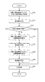
- FIG. 10 is a flow chart showing the flow of the authentication operation performed by the authentication device 3b. It should be noted that the same step numbers are assigned to the processes that have already been explained, and detailed explanation thereof will be omitted.
- the authentication device 3b performs the processes from step S11 to step S14, as in the third embodiment. That is, the illumination control unit 312b controls the illumination device 2 so as to illuminate the eyes of the target person with the illumination light IL (step S11).
- the image analysis unit 311 receives (that is, acquires) the eye image IMG_E from the imaging device 1 (step S12).
- the image analysis unit 311 detects the iris area IA and the reflection area RA (step S13).
- the illumination control unit 312b determines illumination conditions based on the iris area IA and the reflection area RA (step S14).
- the lighting intensity with which the lighting device 2 illuminates the target person may differ from the target intensity set from the viewpoint of appropriately imaging the target person.
- the illumination intensity means the intensity of the lighting device 2 as a whole.
- the illumination intensity is the intensity of the single light when the plurality of illumination lights IL are regarded as a single light. may mean.
- the illumination intensity may fall below the target intensity.
- the brightness of the iris area IA in the eye image IMG_E may be different from the desired brightness.
- the accuracy of authentication of the target person by the iris authentication unit 313 may deteriorate.
- the illumination control unit 312b determines the intensity condition regarding the illumination intensity so that the illumination intensity becomes the target intensity (step S21b). In other words, the illumination control unit 312b determines the intensity condition so that the illumination intensity is kept constant regardless of the difference in illumination conditions (step S21b).
- the intensity condition may include, for example, a condition regarding the intensity of the illumination light IL emitted by at least one light emitting element 21.
- the illumination control unit 312b may determine the intensity of the illumination light IL emitted by at least one light emitting element 21 so that the illumination intensity becomes the target intensity. If the intensity of the illumination light IL emitted by at least one light emitting element 21 is lowered, the illumination intensity is also lowered. That is, when the intensity of the illumination light IL emitted by at least one light emitting element 21 increases, the illumination intensity also increases.
- the intensity condition may include, for example, a condition regarding the number of light emitting elements 21 that emit the illumination light IL.
- the illumination control unit 312b may determine the number of light emitting elements 21 that emit the illumination light IL so that the illumination intensity becomes the target intensity. If the number of light emitting elements 21 that emit the illumination light IL is reduced, the illumination intensity is lowered. In other words, the greater the number of light emitting elements 21 that emit the illumination light IL, the higher the illumination intensity.
- the intensity condition may include, for example, a condition regarding the position of the light emitting element 21 that emits the illumination light IL. In this case, the illumination control section 312b may determine the position of the light emitting element 21 that emits the illumination light IL so that the illumination intensity becomes the target intensity.
- Illumination control unit 312b determines the intensity condition in the same manner as when determining the illumination condition, such that the area of the overlap region where the iris area IA and the reflective area RA overlap is small while the illumination intensity is the target intensity. may For example, when the illumination intensity is lower than the target intensity, the illumination controller 312b typically determines the intensity condition so that the illumination intensity becomes higher. In this case, as a method of increasing the illumination intensity, there are a method of increasing the intensity of the illumination light IL emitted by at least one light emitting element 21 and a method of increasing the number of the light emitting elements 21 emitting the illumination light IL.
- the illumination control unit 312b uses a method of increasing the intensity of the illumination light IL emitted by at least one light emitting element 21 as a method of increasing the illumination intensity, and a method of increasing the number of the light emitting elements 21 emitting the illumination light IL. may be used preferentially.
- the illumination control unit 312b typically determines the intensity condition so that the illumination intensity becomes lower.
- a method of lowering the illumination intensity there are a method of lowering the intensity of the illumination light IL emitted by at least one light emitting element 21 and a method of reducing the number of light emitting elements 21 emitting the illumination light IL.
- the number of light-emitting elements 21 that emit illumination light IL is reduced, the number of reflection areas RA that overlap the iris area IA is reduced (as a result, the area of the overlap area where the iris area IA and the reflection area RA overlap is reduced). become) is possible.
- the illumination control unit 312b reduces the number of light emitting elements 21 that emit the illumination light IL more than the method of lowering the intensity of the illumination light IL emitted by at least one light emitting element 21.
- method may be preferentially used.
- the illumination control unit 312b can determine the intensity condition so that the area of the overlapping area where the iris area IA and the reflective area RA overlap is small while the illumination intensity is the target intensity.
- the illumination control unit 312b selects the light emitting element 21 that emits the illumination light IL rather than changing the position of the light emitting element 21 that emits the illumination light IL.
- the area of the overlapping region where the iris region IA and the reflective region RA overlap becomes more likely to become smaller. Therefore, it is possible to more appropriately reduce the influence of the overlap between the iris area IA and the reflection area RA in the eye image IMG_E on the authentication accuracy.
- the target intensity may be a fixed value.
- the target intensity may be a variable value.
- the lighting controller 312b may change the target intensity.
- the lighting control unit 312b changes the target intensity based on the distance from the imaging device 1 to the target person (or the distance from the lighting device 2 to the target person, which is substantially the position of the target person). You may Specifically, the longer the distance from the imaging device 1 to the target person (or the distance from the illumination device 2 to the target person), the more attenuated illumination light IL reaches the target person. Therefore, the longer the distance from the imaging device 1 to the target person (or the distance from the illumination device 2 to the target person), the more the target person is illuminated with illumination light IL of relatively low intensity. become.
- the lighting control unit 312b changes the target intensity so that the longer the distance from the imaging device 1 to the target person (or the distance from the lighting device 2 to the target person), the higher the target intensity.
- the lighting control unit 312b may change the target intensity based on the moving speed of the target person. Specifically, since the distance from the imaging device 1 to the target person changes (typically becomes shorter) as the target person moves, the optimum value of the target intensity changes as the target person moves. there is a possibility. For this reason, the illumination control unit 312 may change the target intensity so that the target intensity is gradually lowered according to the movement of the target person.
- the illumination control unit 312b may change the target intensity so that the faster the moving speed of the target person is, the faster the reduction speed of the target intensity is.
- the illumination control unit 312b may change the target intensity such that the slower the moving speed of the target person is, the slower the target intensity decreases.
- the lighting control unit 312b may change the target intensity based on the appearance of the target person.
- the reflectance of the illumination light IL may vary depending on the eye color (or skin color, etc.) of the target person. Therefore, light with relatively high intensity can propagate toward the imaging device from the iris of one person, while light with relatively low intensity can propagate from the iris of another person toward the imaging device. have a nature.
- the brightness of the iris area IA in the eye image IMG_E may vary depending on the appearance of the target person. Therefore, the illumination control unit 312b may change the target intensity so that the brightness of the iris area IA in the eye image IMG_E becomes the desired brightness regardless of the difference in appearance of the target person.
- the illumination control unit 312b controls the illumination device 2 so as to illuminate the eyes of the target person with the illumination light IL according to the determined illumination conditions (step S15b).
- the illumination control unit 312b controls the illumination device 2 to illuminate the eyes of the target person with the illumination light IL according to the illumination condition determined in step S14 and the intensity condition determined in step S21b (step S15b).
- the authentication device 3b performs the processing from step S16 to step S17, as in the third embodiment. That is, the iris authentication unit 313 receives (that is, acquires) the eye image IMG_E from the imaging device 1 (step S16). Iris authentication unit 313 authenticates the target person based on acquired eye image IMG_E (step S17).
- the authentication device 3b of the fourth embodiment can determine intensity conditions in addition to illumination conditions. Therefore, when the imaging device 1 captures an image of a target person, the illumination intensity becomes the target intensity (that is, the illumination intensity is kept constant) regardless of the difference in illumination conditions. Therefore, the brightness of the iris area IA in the eye image IMG_E becomes the desired brightness regardless of the difference in illumination conditions. As a result, the authentication device 3b can authenticate the target person with higher accuracy than when the brightness of the iris area IA in the eye image IMG_E is not the desired brightness.
- the authentication device 3b can determine the strength condition based on at least one of the target person's position and the target person's appearance. That is, the authentication device 3b can determine strength conditions suitable for each individual target person. As a result, the authentication device 3b can authenticate the target person with higher accuracy than when the target person is authenticated without considering the target person's position and the target person's appearance.
- the authentication system SYSc differs from the authentication system SYSa described above in that it includes an authentication device 3c instead of the authentication device 3. Other features of the authentication system SYSc may be identical to other features of the authentication system SYSa.
- the authentication device 3c according to the fifth embodiment will be described below with reference to FIG.
- FIG. 11 is a block diagram showing the configuration of an authentication device 3c according to the fifth embodiment.
- the authentication device 3c includes an illumination control unit 312c and an iris authentication unit 313c instead of the illumination control unit 312 and the iris authentication unit 313, unlike the authentication device 3 described above.
- different in Other features of the authentication device 3 c may be identical to other features of the authentication device 3 .
- the illumination control unit 312c differs from the illumination control unit 312 in that the illumination condition is changed each time the imaging device 1 captures an image of the target person.
- Other features of the lighting controller 312 c may be the same as other features of the lighting controller 312 .
- the iris authentication unit 313c differs from the iris authentication unit 313 in that it authenticates a target person based on a plurality of eye images IMG_E.
- FIG. 12 is a flow chart showing the flow of the authentication operation performed by the authentication device 3c.
- the authentication device 3c performs the processes from step S11 to step S16. That is, the illumination control unit 312c controls the illumination device 2 so as to illuminate the eyes of the target person with the illumination light IL (step S11).
- the image analysis unit 311 receives (that is, acquires) the eye image IMG_E from the imaging device 1 (step S12).
- the image analysis unit 311 detects the iris area IA and the reflection area RA (step S13).
- the illumination control unit 312c determines illumination conditions based on the iris area IA and the reflection area RA (step S14).
- the illumination control unit 312c controls the illumination device 2 so as to illuminate the eyes of the target person with the illumination light IL according to the determined illumination conditions (step S15).
- the iris authentication unit 313c receives (that is, acquires) the eye image IMG_E from the imaging device 1 (step S16).
- the image analysis unit 311 detects the iris area IA and the reflection area RA in the eye image IMG_E acquired in step S16 (step S32c).
- the illumination control unit 312c changes the relative position of the reflective area RA with respect to the iris area IA. Illumination conditions are changed (step S33c).
- the illumination control section 312c may change the illumination condition so that the relative position of the reflective area RA overlapping the iris area IA changes.
- FIG. 13(a) shows an example of the iris area IA and the reflection area RA detected in step S32c of FIG.
- two reflective areas RA are located at positions P111 and P112 in the iris area IA, respectively.
- the illumination control unit 312b controls the illumination so that the two reflection areas RA are located at positions P113 and P114, which are different from the positions P111 and P112 in the iris area IA. You can change the conditions.
- the illumination control unit 312c changes the illumination condition regarding the position of the light emitting element 21 that emits the illumination light IL so that the relative position of the reflection area RA with respect to the iris area IA changes. good.
- the illumination control section 312c can relatively easily change the illumination condition so that the relative position of the reflective area RA with respect to the iris area IA is changed.
- the lighting control unit 312c predicts the eye movement of the target person, and changes the lighting conditions so that the relative position of the reflection area RA with respect to the iris area IA changes according to the predicted eye movement.
- the lighting control unit 312 may have a function of predicting the eye movement of the target person in addition to the function of changing the lighting conditions.
- An example of a method for predicting the movement of an object is an existing method (for example, a method using optical flow, etc.).
- FIG. 14(a) shows an example of the iris area IA and the reflection area RA detected in step S32c of FIG.
- two reflective areas RA are located at positions P121 and P122 in the iris area IA, respectively.
- the illumination control unit 312b controls the illumination so that the two reflection areas RA are located at positions P123 and P124, which are different from the positions P121 and P122 in the iris area IA. You can change the conditions.
- the lighting control unit 312c then controls the lighting device 2 based on the lighting conditions changed in step S33c so as to illuminate the eyes of the target person with the illumination light IL according to the lighting conditions changed in step S33c. is controlled (step S34c).
- the iris authentication unit 313c receives (that is, acquires) the eye image IMG_E from the imaging device 1 (step S16). Thereafter, the processes from step SS32c to step S34c and step S16 are repeated until the iris authentication unit 313c acquires a desired number of eye images IMG_E (step S16).
- the iris authentication unit 313c authenticates the target person based on the multiple eye images IMG_E acquired in step S16 (step S17c).
- an example of a plurality of eye images IMG_E acquired in step S16 is shown on the left side of FIG.
- the relative position of the reflection area RA with respect to the iris area IA in the eye image IMG_E obtained the first time is changed from that of the eye image IMG_E obtained the second time. is different from the relative position of the reflective area RA to the iris area IA within.
- a plurality of eye images IMG_E may be combined such that the regions RA are interpolated by non-overlapping portions. As a result, as shown on the right side of FIG.
- an eye image IMG_E with less missing portions in the iris area IA is obtained. That is, an eye image IMG_E corresponding to an image obtained by synthesizing non-missing portions of a plurality of eye images IMG_E is obtained. Based on the eye image IMG_E in which the lacking portion of the iris area IA is reduced in this way (that is, the eye image IMG_E corresponding to the image obtained by synthesizing the non-missing portions of the plurality of eye images IMG_E), the iris authentication unit 313c authenticate a person.
- the iris authentication unit 313c may synthesize a plurality of feature amounts extracted from the plurality of eye images IMG_E. good. In this case as well, iris authentication section 313c extracts the missing portion of the feature amount extracted from one eye image IMG_E (that is, the feature amount that could not be extracted due to reflection area RA) from other eye image IMG_E. A plurality of feature values may be combined so that they are interpolated by each feature value. As a result, as shown on the right side of FIG. 16, a feature amount with fewer missing parts is obtained. That is, a feature amount obtained by synthesizing a plurality of feature amounts extracted from a plurality of eye images IMG_E is obtained. The iris authentication unit 313c may authenticate the target person based on the feature amount with fewer missing parts.
- the authentication device 3c can control the lighting device 2 so as to change the lighting conditions.
- the illumination device 2 illuminates the target person's eyes with illumination light based on one illumination condition, and then illuminates the target person's eyes with illumination light based on another illumination condition different from the one illumination condition.
- the authentication device 3c can authenticate the target person using a plurality of eye images IMG_E each acquired using a plurality of different lighting conditions.
- the authentication device 3c can authenticate the target person with higher accuracy than when the target person is authenticated using a single eye image IMG_E.
- the authentication device 3c can change the lighting conditions so that the relative position of the reflective area RA with respect to the iris area IA changes.
- the authentication device 3c can change the lighting condition so that the relative position of the reflective area RA with respect to the iris area IA is changed. Therefore, as described above, the missing portion of the iris area IA of the image IMG_E of one eye (that is, the portion hidden by the reflection area RA) is replaced by the non-missing portion of the iris area IA of the other eye image IMG_E (that is, the portion that is hidden by the reflection area RA). (portions not hidden by the reflection area RA) can be interpolated. As a result, the authentication device 3c can authenticate the target person with higher accuracy than when the lighting conditions are not changed such that the relative position of the reflective area RA with respect to the iris area IA is changed.
- the authentication device 3c can authenticate the target person using non-missing portions (ie, portions where the reflection areas RA do not overlap) of the multiple eye images IMG_E. Therefore, the authentication device 3c can substantially authenticate the target person using the eye image IMG_E with relatively few missing portions. As a result, the authentication device 3c can authenticate the target person with higher accuracy.
- the authentication device 3c predicts the eye movement of the target person, and adjusts the illumination so that the relative position of the reflection area RA with respect to the iris area IA changes according to the predicted eye movement. Conditions can be changed. As a result, even if the target person's eyes move, the authentication device 3c can change the lighting conditions so that the relative position of the reflective area RA with respect to the iris area IA changes.
- the authentication system SYSb in the above-described fourth embodiment may employ components specific to the fifth embodiment.
- Components specific to the fifth embodiment may include components related to the illumination control unit 312c and the iris authentication unit 313c. (6)
- an illumination control device an illumination control method, a recording medium, and an imaging system
- the lighting control device, the lighting control method, the recording medium, and the authentication system SYSd to which the imaging system in the sixth embodiment is applied will be used to describe the lighting control device, the lighting control method, the recording medium, and the lighting control device in the sixth embodiment.
- an imaging system will be described.
- FIG. 17 is a block diagram showing the configuration of an authentication system SYSd in the sixth embodiment.
- the authentication system SYSd differs from the authentication system SYSa described above in that it includes a plurality of lighting devices 2 .
- the authentication system SYSd includes n lighting devices 2 (specifically, lighting device 2#1 to lighting device 2#n) (where n is a constant representing an integer equal to or greater than 2). It has Other features of the authentication system SYSd may be identical to other features of the authentication system SYSa.
- the plurality of lighting devices 2 are arranged such that the plurality of illumination ranges illuminated by the plurality of lighting devices 2 with the illumination light IL are at least partially different along the vertical direction. .
- the plurality of lighting devices 2 are such that the lighting device 2 #2 has its lighting range located under the lighting device 2 #1 lighting range, and the lighting device 2 #2 has its lighting range located under the lighting device 2 #2. . . , and the illumination range of lighting device 2#n is positioned below the lighting range of lighting device 2#n-1.
- each of the illumination devices 2#1 to 2#n is the same as the above-described illumination device 2, each of the illumination devices 2#1 to 2#n includes a plurality of light emitting elements 21 as in the illumination device 2. It has (6-2) Authentication operation in the sixth embodiment
- FIG. 19 is a flow chart showing the flow of authentication operation in the sixth embodiment.
- the illumination control unit 312d acquires a face image IMG_F generated by imaging the target person's face (step S41d). For example, when the imaging device 1 can generate the face image IMG_F by imaging the face of the target person, the lighting control unit 312 receives the face image IMG_F from the imaging device 1 using the communication device 33 (that is, acquisition). For example, when an imaging device different from the imaging device 1 can generate the face image IMG_F by imaging the face of the target person, the illumination control unit 312 uses the communication device 33 to perform the other imaging. A facial image IMG_F may be received (that is, obtained) from the device.
- the illumination control unit 312d identifies the positions of the eyes of the target person based on the face image IMG_F acquired in step S41d (step S42d). Specifically, the illumination control unit 312d identifies the position (that is, the height) of the target person's eyes in the vertical direction.
- the illumination control unit 312d selects at least one illumination device 2 that actually emits the illumination light IL from among the plurality of illumination devices 2 based on the positions of the eyes identified in step S42d (step S43d). . Specifically, the illumination control unit 312d selects at least one illumination device 2 capable of illuminating the eye located at the position identified in step S42d with the illumination light IL. In other words, the lighting control unit 312d selects at least one lighting device 2 whose lighting range includes the eye located at the position specified in step S42d. For example, FIG. 20 shows an example in which the target person's eyes are included in the lighting range of lighting device 2#2. In this case, in step S43d, the lighting control unit 312d may select the lighting device 2#2.
- At least one illumination device 2 selected in step S43d illuminates the eyes of the target person with illumination light IL.
- at least one illumination device 2 that was not selected in step S43d may not illuminate the eye of the target person with the illumination light IL.
- the authentication device 3d performs the processing from step S11 to step S17, as in the third embodiment.
- the authentication system SYSd of the sixth embodiment selects at least one illumination device 2 that illuminates the eyes of the target person with the illumination light IL according to the position (height) of the eyes of the target person. be able to. Therefore, the authentication system SYSd can appropriately illuminate the target person's eyes with the illumination light IL regardless of the difference in the position (height) of the target person's eyes.
- At least one of the authentication system SYSb in the fourth embodiment to the authentication system SYSc in the fifth embodiment may employ components unique to the sixth embodiment.
- Components specific to the sixth embodiment may include components related to a plurality of lighting devices 2 . (7) Seventh embodiment
- FIG. 21 is a block diagram showing the configuration of an authentication system SYSe in the seventh embodiment.
- the authentication system SYSe differs from the authentication system SYSa described above in that it includes a moving device 4e capable of moving the lighting device 2.
- the moving device 4e may include, for example, a power source such as an actuator, and the lighting device 2 may be moved using the force generated by the power source.
- Other features of the authentication system SYSe may be identical to other features of the authentication system SYSa. (7-2) Authentication operation in the seventh embodiment
- FIG. 22 is a flow chart showing the flow of authentication operation in the seventh embodiment. As shown in FIG. 22, also in the seventh embodiment, the authentication device 3 performs the processing from step S11 to step S14, as in the third embodiment.
- the illumination control unit 312 moves the illumination device 2 by controlling the moving device 4e based on the iris area IA and the reflection area RA (step S54e).
- the lighting control section 312 may move the lighting device 2 so as to achieve the same purpose as when determining the lighting conditions.
- the illumination control section 312 may move the illumination device 2 so as to reduce the influence of the overlapping of the iris area IA and the reflective area RA on the authentication accuracy.
- the illumination control section 312 may move the illumination device 2 so as to reduce the amount of authentication accuracy deterioration caused by the overlapping of the iris area IA and the reflection area RA.
- the illumination control section 312 may move the illumination device 2 so that the authentication accuracy does not deteriorate due to the overlapping of the iris area IA and the reflection area RA.
- the illumination control section 312 may move the illumination device 2 so that the area of the overlap region where the iris area IA and the reflection area RA overlap becomes smaller than before the illumination device 2 is moved.
- the illumination control section 312 may move the illumination device 2 so that the reflective area RA that overlaps the iris area IA disappears.
- the illumination control unit 312 may move the illumination device 2 so that the multiple reflection areas RA are distributed in a specific distribution pattern within the eye image IMG_E.
- the lighting control unit 312 may move the lighting device 2 upward.
- the lighting control unit 312 may move the lighting device 2 downward.
- the lighting control unit 312 may move the lighting device 2 to the right.
- the lighting control unit 312 may move the lighting device 2 to the left.
- the lighting control section 312 may move the lighting device 2 according to the movement of the target person.
- the lighting control unit 312 adjusts the moving direction of the target person at a moving speed that matches the moving speed of the target person so that the positional relationship between the target person and the lighting device 2 is maintained (that is, does not change). You may move the illuminating device 2 toward the same moving direction as . As an example, the lighting control unit 312 controls the lighting device 2 so that the lighting device 2 is positioned on the side of the moving target person, at a moving speed that matches the moving speed of the target person, and in the same moving direction as the moving direction of the target person. You may move the illuminating device 2 toward.
- the operation of moving the lighting device 2 at a moving speed that matches the moving speed of the target person there is an operation of moving the lighting device 2 at the same moving speed as the moving speed of the target person.
- the operation of moving the lighting device 2 at a moving speed that matches the moving speed of the target person there is an operation of moving the lighting device 2 at a moving speed that increases as the moving speed of the target person increases.
- the operation of moving the lighting device 2 at a moving speed that matches the moving speed of the target person there is an operation of moving the lighting device 2 at a moving speed that decreases as the moving speed of the target person decreases.
- the illumination device 2 will also move relatively fast.
- the target person is moving relatively slowly (eg, moving slowly)
- the lighting device 2 will also move relatively quickly (eg, moving slowly).
- the illumination control section 312 does not need to determine the illumination conditions based on the iris area IA and the reflection area RA in step S14. For example, if it is possible to sufficiently reduce the influence of the overlapping of the iris area IA and the reflection area RA on the authentication accuracy by moving the illumination device 2, the illumination control unit 312, in step S14, It is not necessary to determine illumination conditions based on the iris area IA and the reflection area RA. In this case, default lighting conditions may be used.
- the authentication device 3 performs the processing from step S11 to step S17 as in the third embodiment.
- the authentication system SYSe of the seventh embodiment can move the lighting device 2 in addition to or instead of determining lighting conditions. Therefore, even if it is not possible to sufficiently reduce the influence of the overlapping of the iris area IA and the reflective area RA on the authentication accuracy of the target person by simply determining the lighting conditions, the authentication system SYSe By moving the illumination device 2, it is possible to reduce the influence of the overlap between the iris area IA and the reflection area RA on the authentication accuracy. Alternatively, the authentication system SYSe can reduce the influence of the overlapping of the iris area IA and the reflection area RA on the authentication accuracy by moving the illumination device 2 without determining the illumination conditions.
- the operation of moving the lighting device 2 is equivalent to the operation of changing the positional relationship between the lighting device 2 and the target person.
- the positional relationship between the lighting device 2 and the target person can be changed by moving the target person with respect to the lighting device 2 in addition to or instead of moving the lighting device 2 .
- the lighting control unit 312 uses the output device 35 to output to the target person information prompting the target person to move with respect to the lighting device 2 based on the iris area IA and the reflection area RA. good too.
- the lighting control section 312 may output information for moving the target person so as to achieve the same purpose as when determining the lighting conditions.
- the authentication system SYSe can reduce the influence of the overlapping of the iris area IA and the reflection area RA on the authentication accuracy by moving the target person.
- At least one of the authentication system SYSb in the fourth embodiment to the authentication system SYSd in the sixth embodiment may employ components unique to the seventh embodiment.
- Components specific to the seventh embodiment may include components related to movement of the lighting device 2 .
- an eighth embodiment of an illumination control device, an illumination control method, a recording medium, and an imaging system will be described.
- the lighting control device, the lighting control method, the recording medium, and the lighting control device, the lighting control method, the recording medium, the lighting control device, the lighting control method, the recording medium, And an imaging system will be described.
- FIG. 23 is a block diagram showing the configuration of an authentication system SYSf in the eighth embodiment.
- the authentication system SYSf includes an imaging device 1, a right lighting device 2fR, a left lighting device 2fL, and an authentication device 3f.
- a system including the imaging device 1, the right lighting device 2fR, and the left lighting device 2fL may be referred to as an imaging system.
- the right lighting device 2fR can illuminate the target person (especially the eyes) with the illumination light IL. However, the right lighting device 2fR may illuminate at least the right eye of the target person with the illumination light IL. That is, the right lighting device 2fR may not be able to illuminate the left eye of the target person with the illumination light IL. However, the right lighting device 2fR may be able to illuminate the left eye of the target person with the illumination light IL.
- the left lighting device 2fL can illuminate the target person (especially the eyes) with the illumination light IL.
- the left lighting device 2fL may illuminate at least the left eye of the target person with the illumination light IL. That is, the left lighting device 2fL may not be able to illuminate the right eye of the target person with the illumination light IL. However, the left lighting device 2fL may be able to illuminate the right eye of the target person with the illumination light IL.
- the illumination light IL emitted by the right illumination device 2fR is referred to as “illumination light ILR”
- the illumination light IL emitted by the left illumination device 2fL is referred to as “illumination light ILL”. , to distinguish between the two.
- the imaging device 1, the right lighting device 2fR, and the left lighting device 2fL are arranged in the arrangement mode shown in FIG. Specifically, as shown in FIG. 24, the right illumination device 2fR is arranged on the left side of the imaging device 1 (the ⁇ X side in the example shown in FIG. 24) of the imaging device 1.
- the left lighting device 2fL is arranged on the right side of the imaging device 1 (the +X side in the example shown in FIG. 23).
- the left lighting device 2fL is arranged on the right side of the imaging device 1 (the +X side in the example shown in FIG. 24) as viewed from the target person imaged by the imaging device 1 . Furthermore, at the timing when the imaging device 1 captures images of the right eye and the left eye, the optical axis AXR of the right lighting device 2fR (for example, the optical axis of the optical system such as the lens provided in the right lighting device 2fR) and the optical axis AXL of the left lighting device 2fL (For example, the optical axis of an optical system such as a lens included in the left lighting device 2fL) intersects between the imaging device 1 and the target person.
- the right lighting device 2fR may be arranged in the imaging device 1 .
- the right illumination device 2fR may be arranged at a position different from that of the imaging device 1.
- FIG. The right lighting device 2fR may be integrated with the imaging device 1 .
- the right lighting device 2fR may be arranged independently from the imaging device 1.
- the left lighting device 2fL may be arranged in the imaging device 1.
- the left lighting device 2fL may be arranged at a position different from that of the imaging device 1.
- the left lighting device 2fL may be integrated with the imaging device 1.
- FIG. Alternatively, the left lighting device 2fL may be arranged independently from the imaging device 1.
- FIG. When a gate device through which the target person can pass is arranged, at least one of the right lighting device 2fR and the left lighting device 2fL may be arranged in the gate device.
- the imaging device 1 may capture an image of the target passing through the gate device.
- the gate device is, for example, an open state when the target person is permitted to pass through the gate device, and a closed state when the target person is not permitted to pass through the gate device (for example, a flapper gate). gate).
- the authentication device 3f acquires the eye image IMG_E from the imaging device 1, and uses the eye image IMG_E to perform an authentication operation for authenticating the target person.
- the authentication operation performed by the authentication device 3 f is partially different from the authentication operation performed by the authentication device 3 .
- the authentication device 3f uses the eye image IMG_E generated by the imaging device 1 to capture an image of the target person illuminated by the illumination light ILR from the right illumination device 2fR and the illumination light ILL from the left illumination device 2fL.
- the target person is authenticated using both the eye image IMG_E generated by imaging the target person illuminated by the imaging device 1 .
- the eye image IMG_E generated by the imaging device 1 capturing an image of the target person illuminated by the illumination light ILR from the right illumination device 2fR and the eye image IMG_E generated from the image of the target person illuminated by the illumination light ILL from the left illumination device 2fL.
- the target person may be authenticated using either one of the eye images IMG_E generated by the imaging device 1 capturing an image of the target person.
- FIG. 25 shows the configuration of such an authentication device 3f.
- the authentication device 3f differs from the authentication device 3 in that the image analysis unit 311 does not have to be provided. Further, the authentication device 3f differs from the authentication device 3 in that it includes an illumination control section 312f and an iris authentication section 313f instead of the illumination control section 312 and the iris authentication section 313.
- FIG. Other features of the authentication device 3 f may be the same as other features of the authentication device 3 .
- (8-2) Authentication Operation Performed by Authentication Device 3f will be described with reference to FIG.
- FIG. 26 is a flow chart showing the flow of the authentication operation performed by the authentication device 3f.
- the lighting control unit 312f controls the right lighting device 2fR and the left lighting device 2fL so that either one of the right lighting device 2fR and the left lighting device 2fL illuminates the eyes of the target person with the illumination light IL. is controlled (step S61f).
- the lighting control unit 312f controls the right lighting device 2fR and the left lighting device 2fL so that the right lighting device 2fR illuminates the eyes of the target person with the illumination light ILR.
- the illumination control unit 312f controls the right illumination device 2fR so that the right illumination device 2fR illuminates the target person's eyes (particularly, at least the right eye) with the illumination light ILR, and the left illumination device 2fL illuminates the target person's eyes. is not illuminated with the illumination light ILL, the left illumination device 2fL is controlled.
- the lighting control unit 312f controls the right lighting device 2fR so that the right lighting device 2fR emits the illumination light ILR, and controls the left lighting device 2fL so that the left lighting device 2fL does not emit the illumination light ILL. Control.
- the imaging device 1 images the eyes of the target person.
- the target person's eye especially the right eye
- the imaging device 1 captures at least the eye (especially the right eye) of the target person illuminated by the illumination light ILR.
- the imaging device 1 generates an eye image IMG_E. That is, the imaging device 1 generates an eye image IMG_E in which the eye (especially the right eye) of the target person illuminated by the illumination light ILR is captured.
- the eye image IMG_E including the eye (especially the right eye) of the target person illuminated by the illumination light ILR is referred to as an "eye image IMG_ER" as necessary.
- the imaging device 1 generates the eye image IMG_ER
- the iris authentication unit 313f uses the communication device 33 to receive (that is, acquire) the eye image IMG_ER from the imaging device 1 (step S62f).
- the lighting control unit 312f controls the right lighting device 2fR and the left lighting device 2fL so that the other of the right lighting device 2fR and the left lighting device 2fL illuminates the eyes of the target person with the illumination light IL (step S63f).
- the lighting control unit 312f controls the right lighting device 2fR and the left lighting device 2fL so that the left lighting device 2fL illuminates the eyes of the target person with the illumination light ILL.
- the illumination control unit 312f controls the left illumination device 2fL so that the left illumination device 2fL illuminates the target person's eyes (particularly, at least the left eye) with the illumination light ILL, and the right illumination device 2fR illuminates the target person's eyes. is not illuminated with the illumination light ILR, the right illumination device 2fR is controlled.
- the illumination control unit 312 controls the left illumination device 2fL so that the left illumination device 2fL emits illumination light ILL, and controls the right illumination device 2fR so that the right illumination device 2fR does not emit illumination light ILR. Control.
- the imaging device 1 images the eyes of the target person.
- the target person's eye (especially the left eye) is illuminated by the illumination light ILL emitted from the left illumination device 2fL. Therefore, the imaging device 1 captures at least the eye (especially the left eye) of the target person illuminated by the illumination light ILL.
- the imaging device 1 generates an eye image IMG_E. That is, the imaging device 1 generates an eye image IMG_E in which the eye (especially the left eye) of the target person illuminated by the illumination light ILL is captured.
- the eye image IMG_E including the eye (especially the left eye) of the target person illuminated by the illumination light ILL is referred to as "eye image IMG_EL" as necessary.
- the iris authentication unit 313f uses the communication device 33 to receive (that is, obtain) the eye image IMG_EL from the imaging device 1 (step S64f).
- the iris authentication unit 313f authenticates the target person based on the eye image IMG_ER obtained in step S62f and the eye image IMG_EL obtained in step S64f (step S65f). Specifically, the iris authentication unit 313f identifies an iris area IA corresponding to the iris of the right eye of the target person (hereinafter referred to as "iris area IAR" as necessary) in the eye image IMG_ER acquired in step S62f. to detect Further, the iris authentication unit 313f detects an iris area IA corresponding to the iris of the left eye of the target person (hereinafter referred to as "iris area IAL" as necessary) in the eye image IMG_EL acquired in step S64f. .
- the operation of detecting the iris area IA by the iris authentication unit 313f may be the same as the operation of detecting the iris area IA by the iris authentication unit 313 described above. After that, the iris authentication unit 313f extracts the feature amount of the iris pattern from the iris area IAR of the eye image IMG_ER and the iris area IAL of the eye image IMG_EL. After that, the iris authentication unit 313f authenticates the target person by comparing the extracted feature amount with the feature amount of the iris of the registered person. (8-3) Technical effect of authentication system SYSf
- the authentication system SYSf of the eighth embodiment can reduce the influence of the overlap between the iris area IA and the reflection area RA on authentication accuracy.
- the authentication system SYSf can reduce the influence of the overlap between the iris area IA and the reflection area RA on the authentication accuracy when the target person wears glasses. The reason for this will be explained below.
- the reflection area RA may overlap the iris area IA in the eye image IMG_E generated by the imaging device 1 compared to when the target person does not wear the glasses. become more sexual. This is because the illumination light IL for illuminating the target person is reflected by the spectacles (for example, reflected by the lenses of the spectacles).
- the possibility that the iris area IA and the reflection area RA overlap increases as the incident angle ⁇ (see FIGS. 24 and 27) of the illumination light IL with respect to the eyeglass lens covering the eye decreases. That is, the possibility that the iris area IA and the reflective area RA overlap increases as the incident mode of the illumination light to the lens of the spectacles covering the eye approaches vertical incidence.
- the right lighting device 2fR is arranged on the left side of the imaging device 1, and the optical axis AXR of the right lighting device 2fR and the optical axis AXL of the left lighting device 2fL are aligned with the imaging device 1 and the target person. intersect in between.
- the right illumination device 2fR is arranged on the right side of the imaging device 1 and/or the optical axis AXR and the optical axis AXL do not intersect (see FIG. 27), as shown in FIG.
- the incident angle ⁇ of the illumination light ILR with respect to the right lens of the spectacles covering the right eye increases.
- the left lighting device 2fL is arranged on the right side of the imaging device 1, and the optical axis AXR of the right lighting device 2fR and the optical axis AXL of the left lighting device 2fL are aligned with the imaging device 1. Intersect between people. As a result, compared to the case where the left illumination device 2fL is arranged on the left side of the imaging device 1 and/or the optical axis AXR and the optical axis AXL do not intersect (see FIG. 27), as shown in FIG. The incident angle ⁇ of the illumination light ILL with respect to the left lens of the spectacles covering the left eye increases. As a result, as shown in FIG.
- the image pickup device 1 can detect the iris region IAR.
- An eye image IMG_ER can be generated in which the reflective areas RA do not overlap.
- the image pickup device 1 can detect the iris region IAL.
- An eye image IMG_EL can be generated in which the reflective areas RA do not overlap.
- the left lens of the spectacles covering the left eye is The incident angle of the illumination light ILR with respect to is not necessarily large enough. Therefore, as shown in FIG. 28A, there is a possibility that the reflective area RA overlaps the iris area IAL corresponding to the iris of the left eye in the eye image IMG_ER.
- the right lens of the spectacles covering the right eye The incident angle of the illumination light ILL with respect to is not necessarily large enough. Therefore, as shown in FIG. 28B, in the eye image IMG_EL, there is a reflection area RA in the iris area IAR corresponding to the iris of the right eye. Based on this point, in the eighth embodiment, the iris authentication unit 313f extracts the feature amount related to the iris pattern from the iris area IAR that is unlikely to overlap the reflection area RA in the eye image IMG_ER.
- the iris authentication unit 313f extracts the feature amount related to the iris pattern from the iris area IAL that is unlikely to overlap the reflective area RA, while the iris authentication unit 313f It is not necessary to extract the feature amount related to the iris pattern from the iris area IAR having the characteristic. After that, the iris authentication unit 313 authenticates the target person using the feature amount extracted from the iris area IAR of the eye image IMG_ER and the feature amount extracted from the iris area IAL of the eye image IMG_EL.
- the iris authentication unit 313 extracts the feature amount extracted from the iris area IAL of the eye image IMG_ER on which the reflection area RA may overlap, and the iris area of the eye image IMG_EL on which the reflection area RA may overlap.
- the iris authentication unit 313 can identify the target person with higher accuracy than when the target person is authenticated using the feature amount extracted from the iris area IA that may overlap with the reflection area RA. can be authenticated.
- iris authentication section 313 may authenticate the target person using either one of the feature amount extracted from the iris area IAR of the eye image IMG_ER and the feature amount extracted from the iris area IAL of the eye image IMG_EL.
- iris authentication section 313 does not have to authenticate the target person using both the feature amount extracted from the iris area IAR of the eye image IMG_ER and the feature amount extracted from the iris area IAL of the eye image IMG_EL. . Even in this case, the iris authentication unit 313 can authenticate the target person with a correspondingly high accuracy.
- the authentication device 3f may perform an authentication operation related to face authentication in addition to the authentication operation related to iris authentication.
- An authentication operation related to face authentication acquires a face image IMG_F (see the sixth embodiment) generated by imaging a target person's face, and obtains feature points (feature points) of the target person's face reflected in the face image IMG_F.
- the authentication device 3f may perform the authentication operation for face authentication before, after, or in parallel with the authentication operation for iris authentication.
- the authentication device 3f may control the illumination intensity when generating the eye image IMG_E based on the face authentication result. good.
- the authentication device 3f may set (for example, change) a threshold value Th corresponding to the allowable size of the overlap area where the iris area IA and the reflection area RA overlap, based on the result of face authentication.
- the authentication device 3f typically sets the lighting conditions ( For example, the number of light emitting elements 21 that emit the illumination light IL described in the third embodiment, etc.) may be set.
- the authentication device 3f may output information prompting the target person to move such that the size of the overlapping area is smaller than the threshold Th. In this case, the smaller the threshold Th, the smaller the overlapping area where the iris area IA and the reflection area RA overlap.
- the authentication device 3f can authenticate the target person with higher accuracy by iris authentication. Conversely, as the threshold Th increases, the overlap between the iris area IA and the reflective area RA is allowed to some extent, so the burden of setting the lighting conditions of the right lighting device 2fR and the left lighting device 2fL is reduced. On this premise, when face authentication fails, it is preferable to give priority to reliable authentication of the target person by iris authentication because the authentication of the target person has not been completed. Therefore, the authentication device 3f may make the threshold Th smaller when face authentication fails than when face authentication succeeds.
- the imaging device 1 can capture the eye of the target person under an appropriate imaging environment (that is, under an environment in which the overlapping area where the iris area IA and the reflective area RA overlap is small). An appropriately reflected eye image IMG_E is generated.
- the authentication device 3f can more reliably determine whether or not the target person is the same as the registered person by performing iris authentication. Conversely, when the face recognition is successful, since the target person has already been authenticated by the face authentication, the right lighting device 2fR and the left lighting device 2fL for iris authentication are used rather than improving the accuracy of the target person authentication. Even if priority is given to reducing the burden of setting lighting conditions, no major problems will arise. Therefore, the authentication device 3f may increase the threshold Th when the face authentication is successful compared to when the face authentication is unsuccessful.
- At least one of the right lighting device 2fR and the left lighting device 2fL may be capable of changing the lighting mode of the illumination light IL for the eyes of the target person, like the lighting device 2 described above.
- At least one of the right lighting device 2fR and the left lighting device 2fL may include a plurality of light emitting elements 21, like the lighting device 2 described above.
- the authentication device 3f may include an image analysis section 311 that detects the iris area IA and the reflection area RA.
- the illumination control section 312f may determine illumination conditions based on the iris area IA and the reflection area RA, similarly to the illumination control section 312 described above.
- At least one of the authentication system SYSa in the third embodiment to the authentication system SYSe in the seventh embodiment may employ components unique to the eighth embodiment.
- Components specific to the eighth embodiment may include components related to the right lighting device 2fR and the left lighting device 2fL.
- the authentication system SYSg differs from the authentication system SYSf described above in that it includes an authentication device 3g instead of the authentication device 3f. Other features of the authentication system SYSg may be identical to other features of the authentication system SYSf.
- the authentication device 3g in the ninth embodiment will be described below with reference to FIG.
- FIG. 29 is a block diagram showing the configuration of an authentication device 3g in the ninth embodiment.
- the authentication device 3g differs from the above-described authentication device 3f in that it includes an illumination control section 312g instead of the illumination control section 312f.
- Other features of the authentication device 3g may be the same as other features of the authentication device 3f.
- the lighting control unit 312g controls the right lighting device 2fR and the left lighting device 2fL so that both the right lighting device 2fR and the left lighting device 2fL illuminate the eyes of the target person with the illumination light IL, compared with the lighting control unit 312f. different in terms of control.
- Other features of the lighting controller 312g may be the same as other features of the lighting controller 312f.
- FIG. 30 is a flow chart showing the flow of the authentication operation performed by the authentication device 3g.
- the lighting control unit 312g controls the right lighting device 2fR and the left lighting device 2fL so that both the right lighting device 2fR and the left lighting device 2fL illuminate the eyes of the target person with the illumination light IL. (step S71g). That is, the lighting control unit 312g controls the right lighting device 2fR so that the right lighting device 2fR illuminates the target person's eyes with the illumination light ILR, and the left lighting device 2fL illuminates the target person's eyes with the illumination light ILL.
- the left lighting device 2fL is controlled so as to In other words, the lighting control unit 312f controls the right lighting device 2fR so that the right lighting device 2fR emits the illumination light ILR, and controls the left lighting device 2fL so that the left lighting device 2fL emits the illumination light ILL. Control.
- the imaging device 1 images the eyes of the target person (in this case, both the right eye and the left eye).
- the imaging device 1 generates an eye image IMG_E. That is, the imaging device 1 generates an eye image IMG_E in which the target person's eyes (in this case, both the right eye and the left eye) illuminated by the illumination light ILR and the illumination light ILL are captured.
- the eye image IMG_E including the eyes of the target person illuminated by the illumination light ILR and the illumination light ILL is defined as " is referred to as an eye image IMG_EB".
- the illumination control unit 312g uses the communication device 33 to receive (that is, obtain) the eye image IMG_EB from the imaging device 1 (step S72g).
- the lighting control unit 312g determines whether or not the quality of the iris reflected in the eye image IMG_EB is good (step S73g). For example, the illumination control unit 312g detects the iris area IA and the reflection area RA in the eye image IMG_EB, and the ratio of the overlapping area where the iris area IA and the reflection area RA overlap to the iris area IA is equal to or less than the allowable upper limit. It may be determined whether or not In this case, illumination control section 312g controls the iris reflected in eye image IMG_EB when the ratio of overlapping area where iris area IA and reflective area RA overlap with respect to iris area IA is equal to or less than the allowable upper limit. It may be determined that the quality is good.
- the illumination control unit 312g may detect the iris area IA in the eye image IMG_EB and determine whether or not the feature amount related to the iris pattern can be extracted from the detected iris area IA. In this case, the lighting control unit 312g may determine that the quality of the iris reflected in the eye image IMG_EB is good when the feature amount of the iris pattern can be extracted from the iris area IA. For example, the illumination control unit 312g may determine whether or not the target person can be authenticated using the eye image IMG_EB. In this case, the illumination control unit 312g may determine that the quality of the iris reflected in the eye image IMG_EB is good when the target person can be authenticated using the eye image IMG_EB.
- step S73g if it is determined that the quality of the iris is not good (step S73g: No), the reflective area RA with respect to the iris area IA will adversely affect the authentication accuracy of the target person. It is assumed that they are likely to overlap. Therefore, in this case, the authentication device 3g performs the above-described steps S61f to S64f as in the eighth embodiment. As a result, the iris authentication unit 313f obtains an eye image IMG_ER in which the reflective area RA does not overlap the iris area IAR and an eye image IMG_EL in which the reflective area RA does not overlap the iris area IAL. After that, the iris authentication unit 313f performs the operation of step S65f described above.
- the iris authentication unit 313f authenticates the target person using the feature amount related to the iris pattern extracted from the iris area IAR of the eye image IMG_ER and the iris area IAL of the eye image IMG_EL.
- the authentication device 3f uses either one of the feature amount related to the iris pattern extracted from the iris area IAR of the eye image IMG_ER and the iris area IAL of the eye image IMG_EL. , may authenticate the target person.
- step S73g determines whether the quality of the iris is good. If the result of determination in step S73g is that the quality of the iris is good (step S73g: Yes), the iris authentication unit 313f can authenticate the target person using the eye image IMG_EB. (That is, the iris feature amount can be extracted to the extent that the target person can be authenticated from the eye image IMG_EB). That is, it is assumed that the iris authentication unit 313f can authenticate the target person without newly acquiring the eye images IMG_ER and IMG_EL. Therefore, in this case, the authentication device 3g does not need to perform the above-described steps S61f to S64f. In this case, the iris authenticating unit 313f may authenticate the target person using the feature amount relating to the iris pattern extracted from at least one of the iris areas IAR and IAL of the eye image IMG_EB (step S65f).
- the authentication system SYSg of the ninth embodiment does not necessarily need to generate the eye images IMG_ER and IMG_EL. Therefore, compared to the case where the eye images IMG_ER and IMG_EL are always generated, the time required for authenticating the target person can be shortened.
- the illumination light is applied to the iris area IAL corresponding to the iris of the left eye in the eye image IMG_EB.
- the reflection area RA of the ILR overlaps and/or the reflection area RA of the illumination light ILL overlaps with the iris area IAR corresponding to the iris of the right eye. Therefore, the authentication system SYSg normally separately generates an eye image IMG_ER in which the reflective area RA does not overlap the iris area IAR and an eye image IMG_EL in which the reflective area RA does not overlap the iris area IAL.
- the reflection area RA of the illumination light ILR may not overlap the iris area IAL and the reflection area RA of the illumination light ILL may not overlap the iris area IAR in the eye image IMG_EB.
- the iris area IAL may overlap with the reflective area RA of the illumination light ILR, but the iris area IAR may not overlap with the reflective area RA of the illumination light ILL.
- the reflection area RA of the illumination light ILR overlaps the iris area IAR while the reflection area RA of the illumination light ILR does not overlap the iris area IAL.
- the authentication system SYSg need not generate the eye images IMG_ER and IMG_EL separately from the eye images IMG_EB. As a result, the number of times the eye image IMG_E is generated is reduced compared to the case where the eye images IMG_ER and IMG_EL are always generated. Therefore, the authentication system SYSg can shorten the time required to authenticate the target person. (10) Tenth embodiment
- the authentication system SYSh differs from the authentication system SYSf described above in that it includes an authentication device 3h instead of the authentication device 3f. Other features of the authentication system SYSh may be identical to other features of the authentication system SYSf.
- the authentication device 3h in the tenth embodiment will be described below with reference to FIG.
- FIG. 31 is a block diagram showing the configuration of an authentication device 3h according to the tenth embodiment.
- the authentication device 3h differs from the authentication device 3f described above in that it includes a lighting control section 312h instead of the lighting control section 312f.
- Other features of the authentication device 3h may be the same as other features of the authentication device 3f.
- the illumination control unit 312h controls the illumination intensity with which the illumination device 2 illuminates the target person so that the brightness of the eye area EA (see FIG. 33 described later) in the face image IMG_F becomes the target brightness compared with the illumination control unit 312f. is adjustable.
- Other features of the lighting controller 312h may be the same as other features of the lighting controller 312f.
- FIG. 32 is a flow chart showing the flow of the authentication operation performed by the authentication device 3h.
- the illumination control unit 312h acquires a face image IMG_F generated by imaging the face of the target person (step S91h). For example, when the imaging device 1 can generate the face image IMG_F by imaging the face of the target person, the illumination control unit 312h receives the face image IMG_F from the imaging device 1 using the communication device 33 (that is, acquisition). For example, when an imaging device different from the imaging device 1 can generate the face image IMG_F by imaging the face of the target person, the illumination control unit 312h uses the communication device 33 to perform the other imaging. A facial image IMG_F may be received (that is, obtained) from the device.
- the lighting control unit 312h identifies an eye area EA, which is a predetermined-shaped area including the eyes of the target person, in the face image IMG_F obtained in step S91h (step S92h).
- An example of the eye area EA is shown in FIG.
- the eye area EA may be a rectangular area containing an eye.
- the eye area EA may be a rectangular area that includes the eye and the area near the eye.
- the size of the eye area EA may be sized according to the size of the eye.
- the lighting control unit 312h calculates the brightness of the eye area EA as the calculated brightness, and based on the calculated brightness of the eye area EA and the target brightness preset as the target value of the brightness of the eye area EA in the eye image IMG_E. to adjust the illumination intensity with which the illumination device 2 illuminates the target person (step S93h). Specifically, the lighting control unit 312h adjusts the lighting intensity by setting a target value for the lighting intensity based on the calculated luminance and the target luminance. For example, if the calculated brightness is higher than the target brightness, it is assumed that the current illumination intensity is high relative to the ideal intensity. Therefore, in this case, the illumination control unit 312h may adjust the illumination intensity so that the current illumination intensity is lowered.
- the lighting control unit 312h may adjust the lighting intensity so that the current lighting intensity becomes lower by setting a new target value for the lighting intensity lower than the current lighting intensity.
- the lighting control unit 312h may adjust the lighting intensity so that the current lighting intensity becomes higher.
- the illumination control unit 312h may adjust the illumination intensity so that the current illumination intensity becomes higher by setting a new target value of the illumination intensity higher than the current illumination intensity.
- the authentication device 3h can adjust the illumination intensity so that the brightness of the eye area EA of the face image IMG_F is the target brightness.
- the brightness of the iris area IA of the eye image IMG_E becomes the desired brightness corresponding to the target brightness. Therefore, the authentication device 3h can authenticate the target person using the eye image IMG_E in which the brightness of the iris area IA is the desired brightness. Therefore, the authentication device 3h can authenticate the target person with higher accuracy than when the target person is authenticated using the eye image IMG_E in which the brightness of the iris area IA is not the target brightness. .
- the illumination control unit 312h controls that the right illumination device 2fR illuminates the target person with the illumination light ILR and the left illumination device 2fL illuminates the target person with the illumination light ILL.
- the luminance of the iris area IA obtained under a first illumination environment without the luminance, and the left illumination device 2fL illuminating the target person with the illumination light ILL, while the right illumination device 2fR illuminates the target person with the illumination light ILR.
- the brightness of the iris area IA of the eye image IMG_EL acquired under a second illumination environment that is not illuminated, the right illumination device 2fR illuminating the target person with illumination light ILR, and the left illumination device 2fL illuminating the target person with illumination light ILL.
- the illumination intensity may be adjusted so that the brightness of the iris area IA of the eye image IMG_EB acquired under the illuminated third illumination environment is the same.
- the lighting control unit 312h sets the target value of the lighting intensity under the first lighting environment by performing steps S91h to S93h described above under the first lighting environment.
- steps S91h to S93h described below the target value of the illumination intensity under the second illumination environment is set, and by performing steps S91h to S93h described above under the third illumination environment, A target value of illumination intensity under a third illumination environment may be set.
- the authentication device 3h can authenticate the target person with higher accuracy than when the luminance of the iris area IA of the eye image IMG_EB varies depending on the lighting environment.
- At least one of the authentication system SYSa according to the third embodiment to the authentication system SYSe according to the seventh embodiment may employ components unique to the tenth embodiment. Components specific to the tenth embodiment may include components related to illumination intensity adjustment. (11) Supplementary notes The following supplementary notes are disclosed with respect to the above-described embodiments.
- Appendix 1 An iris region corresponding to the iris of the eye and a reflection region corresponding to the reflected image of the illumination light in an eye image generated by imaging the eye of a subject illuminated by illumination light from an illumination device. a detection means for detecting and lighting control means for controlling the lighting device based on a state of overlap between the iris area and the reflection area.
- the lighting device includes a plurality of light emitting units each capable of emitting the illumination light, The illumination control means controls, based on the overlapping state, the number of the light emitting units that emit the illumination light, the positions of the light emitting units that emit the illumination light, and the light emitting units that emit the illumination light.
- the lighting control device according to Supplementary Note 1, wherein a lighting condition including at least one of an angle to be projected and an intensity of the illumination light emitted by the light emitting unit is determined, and the lighting device is controlled based on the determined lighting condition.
- Appendix 3 3. The lighting control device according to appendix 1 or 2, wherein the lighting control means controls the lighting device so as to reduce an area of an overlap region where the iris region and the reflection region overlap.
- [Appendix 4] 4. The lighting control device according to any one of appendices 1 to 3, wherein the lighting control means controls the lighting device such that the reflection areas are distributed in a specific distribution pattern.
- [Appendix 5] 5. The lighting control device according to any one of appendices 1 to 4, wherein the lighting control means controls the lighting device so that the reflection area blinks at specific time intervals.
- the lighting device includes a plurality of light emitting units each capable of emitting the illumination light, The illumination control means determines intensity conditions including at least one of the number and positions of the light emitting units for emitting the illumination light based on at least one of the position, appearance, and moving speed of the target. 6.
- the lighting control device according to any one of appendices 1 to 5, wherein the lighting device is controlled based on the intensity condition.
- the illumination control means illuminates the eye with the illumination light under a first illumination condition, and then illuminates the eye with the illumination light under a second illumination condition different from the first illumination condition. 7.
- the lighting control device according to any one of appendices 1 to 6, wherein the lighting device is controlled.
- the illumination control means controls the position of the reflection area with respect to the iris area in a first eye image generated by imaging the eye illuminated with the illumination light under the first illumination condition. , a position of the reflective region with respect to the iris region in a second eye image generated by imaging the eye illuminated with the illumination light under the second illumination condition.
- the lighting control device according to any one of additional notes 1 to 11, further comprising output means for outputting to the object information prompting the lighting device to move the object based on the overlapping state.
- Appendix 13 An iris region corresponding to the iris of the eye and a reflection region corresponding to the reflected image of the illumination light in an eye image generated by imaging at least the eye of the object illuminated by the illumination light from the illumination device. and and controlling the lighting device based on a state of overlap between the iris area and the reflection area.
- Appendix 14 to the computer, An iris region corresponding to the iris of the eye and a reflection region corresponding to the reflected image of the illumination light in an eye image generated by imaging at least the eye of the object illuminated by the illumination light from the illumination device.
- a recording medium recording a computer program for executing an illumination control method comprising: controlling the illumination device based on the state of overlap between the iris area and the reflection area.
- a right illumination device that emits right illumination light capable of illuminating at least the right eye of a subject
- a left illumination device that emits left illumination light capable of illuminating at least the left eye of the subject
- an imaging device that images the right eye illuminated with the right illumination light and the left eye illuminated with the left illumination light
- the right lighting device is arranged on the left side of the imaging device facing the imaging device
- the left lighting device is arranged on the right side of the imaging device facing the imaging device
- An imaging system wherein an optical axis of the right lighting device and an optical axis of the left lighting device intersect between the imaging device and the object at timings when the imaging device images the right eye and the left eye.
- the imaging device captures an image of the right eye under a first lighting environment in which the right lighting device emits the right illumination light and the left lighting device does not emit the left illumination light
- the imaging device according to attachment 15 wherein the imaging device captures the image of the left eye under a second lighting environment in which the left lighting device emits the left illumination light and the right lighting device does not emit the right illumination light.
- [Appendix 17] information about the iris of the right eye reflected in a first eye image generated by imaging the right eye by the imaging device under the first lighting environment; The subject is authenticated based on the information about the iris of the left eye reflected in the second eye image generated by imaging the. 17.
- Appendix 18 the imaging device images both the right eye and the left eye under a third lighting environment in which the right lighting device emits the right illumination light and the left lighting device emits the left illumination light; (i) the iris of the right eye and the left eye reflected in a third eye image generated by the imaging device capturing images of both the right eye and the left eye under the third lighting environment; imaging the right eye under the first lighting environment and imaging the left eye under the second lighting environment if the iris quality does not meet the desired condition; and (ii) the quality meets the desired condition. 18.
- the right illuminating device and the left illuminating device control the brightness of the iris of the right eye in a first eye image generated by imaging the right eye with the imaging device under the first lighting environment, and the brightness of the iris of the right eye in the second lighting environment.
Landscapes
- Engineering & Computer Science (AREA)
- Theoretical Computer Science (AREA)
- Physics & Mathematics (AREA)
- General Physics & Mathematics (AREA)
- Multimedia (AREA)
- Health & Medical Sciences (AREA)
- Human Computer Interaction (AREA)
- General Health & Medical Sciences (AREA)
- General Engineering & Computer Science (AREA)
- Ophthalmology & Optometry (AREA)
- Life Sciences & Earth Sciences (AREA)
- Computer Vision & Pattern Recognition (AREA)
- Biophysics (AREA)
- Pathology (AREA)
- Biomedical Technology (AREA)
- Heart & Thoracic Surgery (AREA)
- Medical Informatics (AREA)
- Molecular Biology (AREA)
- Surgery (AREA)
- Animal Behavior & Ethology (AREA)
- Public Health (AREA)
- Veterinary Medicine (AREA)
- Image Input (AREA)
- Measurement Of The Respiration, Hearing Ability, Form, And Blood Characteristics Of Living Organisms (AREA)
Abstract
Description
(1)第1実施形態
(2)第2実施形態
右照明装置2001は、撮像装置2003に配置されていてもよい。右照明装置2001は、撮像装置2003とは異なる位置に配置されていてもよい。右照明装置2001は、撮像装置2003と一体化されていてもよい。右照明装置2001は、撮像装置2003と別個独立に配置されていてもよい。左照明装置2002は、撮像装置2003に配置されていてもよい。左照明装置2002は、撮像装置2003とは異なる位置に配置されていてもよい。左照明装置2002は、撮像装置2003と一体化されていてもよい。或いは、左照明装置2002は、撮像装置2003と別個独立に配置されていてもよい。
対象が通過可能なゲート装置が配置されている場合には、右照明装置2001及び左照明装置2002の少なくとも一つは、ゲート装置に配置されていてもよい。対象が通過可能なゲート装置が配置されている場合には、撮像装置2003は、ゲート装置を通過する対象を撮像してもよい。
(3)第3実施形態
(3-1)認証システムSYSaの全体構成
図3に示すように、認証システムSYSaは、撮像装置1と、照明装置2と、認証装置3とを備える。
(3-2)認証装置3の構成
続いて、図4を参照しながら、認証装置3の構成について説明する。図4は、認証装置3の構成を示すブロック図である。
(3-3)認証装置3が行う認証動作
続いて、図5を参照しながら、認証装置3が行う認証動作について説明する。図5は、認証装置3が行う認証動作の流れを示すフローチャートである。
照明条件を決定する方法の一例として、照明制御部312は、虹彩領域IAと反射領域RAとが重なる重複領域の面積が大きい(例えば、所定の面積閾値よりも多い)場合に、照明光ILを射出する発光素子21の数が減るように、照明条件(特に、照明光ILを射出する発光素子21の数に関する照明条件)を決定してもよい。この場合、虹彩領域IAと反射領域RAとが重なる重複領域の面積が小さくなるがゆえに、虹彩領域IAと反射領域RAとの重なりが虹彩認証部313による対象人物の認証精度に対して与える影響が低減される。
照明条件を決定する方法の他の一例として、照明制御部312は、虹彩領域IAと重なる反射領域RAの数が多い(例えば、所定の数閾値よりも多い)場合には、照明制御部312は、照明光ILを射出する発光素子21の数が減るように照明条件(特に、照明光ILを射出する発光素子21の数に関する照明条件)を決定してもよい。この場合、虹彩領域IAに重なる反射領域RAの数が少なくなるがゆえに、虹彩領域IAと反射領域RAとの重なりが虹彩認証部313による対象人物の認証精度に対して与える影響が低減される。
照明条件を決定する方法の他の一例として、照明制御部312は、虹彩領域IAと重なる反射領域RAの輝度が高い(例えば、所定の輝度閾値よりも多い)場合には、照明制御部312は、照明光ILを射出する発光素子21の数が減るように照明条件(特に、照明光ILを射出する発光素子21の数に関する照明条件)を決定してもよい。この場合、虹彩領域IAに重なる反射領域RAの数が少なくなるがゆえに、虹彩領域IAと反射領域RAとの重なりが虹彩認証部313による対象人物の認証精度に対して与える影響が低減される。
照明条件を決定する方法の他の一例として、照明制御部312は、虹彩領域IAと反射領域RAとが重なる重複領域の面積が大きい場合に、照明光ILで虹彩を照明する発光素子21の位置が変わるように、照明条件(特に、照明光ILを射出する発光素子21の位置に関する照明条件)を決定してもよい。この場合、照明制御部312は、虹彩領域IAと反射領域RAとが重なる重複領域の面積が小さくなるように、照明光ILで虹彩を照明する発光素子21の位置を変更してもよい。その結果、虹彩領域IAと反射領域RAとが重なる重複領域の面積が小さくなるがゆえに、虹彩領域IAと反射領域RAとの重なりが虹彩認証部313による対象人物の認証精度に対して与える影響が低減される。
照明条件を決定する方法の他の一例として、照明制御部312は、虹彩領域IAと重なる反射領域RAの数が多い場合に、照明光ILで虹彩を照明する発光素子21の位置が変わるように、照明条件(特に、照明光ILを射出する発光素子21の位置に関する照明条件)を決定してもよい。この場合、照明制御部312は、虹彩領域IAと重なる反射領域RAの数が少なくなるように、照明光ILで虹彩を照明する発光素子21の位置を変更してもよい。その結果、虹彩領域IAと反射領域RAとが重なる重複領域の面積が小さくなるがゆえに、虹彩領域IAと反射領域RAとの重なりが虹彩認証部313による対象人物の認証精度に対して与える影響が低減される。
照明条件を決定する方法の他の一例として、照明制御部312は、虹彩領域IAと重なる反射領域RAの輝度が高い場合に、照明光ILで虹彩を照明する発光素子21の位置が変わるように、照明条件(特に、照明光ILを射出する発光素子21の位置に関する照明条件)を決定してもよい。この場合、照明制御部312は、虹彩領域IAと重なる反射領域RAの輝度が低くなるように、照明光ILで虹彩を照明する発光素子21の位置を変更してもよい。反射領域RAの輝度が高くなるほど、反射領域RAが目画像IMG_E内において白とびの状態にある可能性が高くなる。このため、反射領域RAの輝度が高くなるほど、虹彩領域IAのうち少なくとも一つの反射領域RAが重なっている部分から、虹彩のパターンに関する特徴量を抽出することができる可能性が低くなる。逆に言えば、反射領域RAの輝度が低くなるほど、虹彩領域IAのうち少なくとも一つの反射領域RAが重なっている部分から、虹彩のパターンに関する特徴量を抽出することができる可能性が高くなる。典型的には、照明制御部312は、虹彩領域IAと重なる反射領域RAの輝度が低くなることで反射領域RAが消滅するように、照明光ILで虹彩を照明する発光素子21の位置を変更してもよい。その結果、虹彩領域IAと反射領域RAとが重なる重複領域の面積が小さくなるがゆえに、虹彩領域IAと反射領域RAとの重なりが虹彩認証部313による対象人物の認証精度に対して与える影響が低減される。
照明条件を決定する方法の他の一例として、照明制御部312は、虹彩領域IAと反射領域RAとが重なる重複領域の面積が大きい場合に、対象人物の目を照明する照明光ILを射出している発光素子21が照明光ILを射出する角度が変わるように、照明条件(特に、発光素子21が照明光ILを射出する角度に関する照明条件)を決定してもよい。この場合、照明制御部312は、虹彩領域IAと反射領域RAとが重なる重複領域の面積が小さくなるように、発光素子21が照明光ILを射出する角度を変更してもよい。その結果、虹彩領域IAと反射領域RAとが重なる重複領域の面積が小さくなるがゆえに、虹彩領域IAと反射領域RAとの重なりが虹彩認証部313による対象人物の認証精度に対して与える影響が低減される。
照明条件を決定する方法の他の一例として、照明制御部312は、虹彩領域IAと重なる反射領域RAの数が多い場合に、対象人物の目を照明する照明光ILを射出している発光素子21が照明光ILを射出する角度が変わるように、照明条件(特に、発光素子21が照明光ILを射出する角度に関する照明条件)を決定してもよい。この場合、照明制御部312は、虹彩領域IAと重なる反射領域RAの数が少なくなるように、発光素子21が照明光ILを射出する角度を変更してもよい。その結果、虹彩領域IAと重なる反射領域RAの数が少なくなるがゆえに、虹彩領域IAと反射領域RAとの重なりが虹彩認証部313による対象人物の認証精度に対して与える影響が低減される。
照明条件を決定する方法の他の一例として、照明制御部312は、虹彩領域IAと重なる反射領域RAの輝度が高い場合に、対象人物の目を照明する照明光ILを射出している発光素子21が照明光ILを射出する角度が変わるように、照明条件(特に、発光素子21が照明光ILを射出する角度に関する照明条件)を決定してもよい。この場合、照明制御部312は、虹彩領域IAと重なる反射領域RAの輝度が低くなるように、発光素子21が照明光ILを射出する角度を変更してもよい。その結果、虹彩領域IAと反射領域RAとが重なる重複領域の面積が小さくなるがゆえに、虹彩領域IAと反射領域RAとの重なりが虹彩認証部313による対象人物の認証精度に対して与える影響が低減される。
照明条件を決定する方法の他の一例として、照明制御部312は、虹彩領域IAと反射領域RAとが重なる重複領域の面積が大きい場合に、対象人物の目を照明している照明光ILの強度が変わるように、照明条件(特に、発光素子21が射出する照明光ILの強度に関する照明条件)を決定してもよい。この場合、照明制御部312は、虹彩領域IAと反射領域RAとが重なる重複領域の面積が小さくなるように、発光素子21が射出する照明光ILの強度を変更してもよい。例えば、照明制御部312は、対象人物の目(特に、虹彩)を照明している照明光ILの強度が低くなるように、発光素子21が射出する照明光ILの強度を変更してもよい。その結果、照明光ILの強度が高いままである場合と比較して、反射像が形成されにくくなる。このため、虹彩領域IAと反射領域RAとが重なる重複領域の面積が小さくなるがゆえに、虹彩領域IAと反射領域RAとの重なりが虹彩認証部313による対象人物の認証精度に対して与える影響が低減される。
照明条件を決定する方法の他の一例として、照明制御部312は、虹彩領域IAと重なる反射領域RAの数が多い場合に、対象人物の目を照明している照明光ILの強度が変わるように、照明条件(特に、発光素子21が射出する照明光ILの強度に関する照明条件)を決定してもよい。この場合、照明制御部312は、虹彩領域IAと重なる反射領域RAの数が少なくなるように、発光素子21が射出する照明光ILの強度を変更してもよい。例えば、照明制御部312は、対象人物の目(特に、虹彩)を照明している照明光ILの強度が低くなるように、発光素子21が射出する照明光ILの強度を変更してもよい。その結果、照明光ILの強度が高いままである場合と比較して、反射像が形成されにくくなる。このため、虹彩領域IAと重なる反射領域RAの数が少なくなるがゆえに、虹彩領域IAと反射領域RAとの重なりが虹彩認証部313による対象人物の認証精度に対して与える影響が低減される。
照明条件を決定する方法の他の一例として、照明制御部312は、虹彩領域IAと重なる反射領域RAの輝度が高い場合に、対象人物の目を照明している照明光ILの強度が変わるように、照明条件(特に、発光素子21が射出する照明光ILの強度に関する照明条件)を決定してもよい。この場合、照明制御部312は、虹彩領域IAと重なる反射領域RAの輝度が低くなるように、発光素子21が射出する照明光ILの強度を変更してもよい。その結果、虹彩領域IAと反射領域RAとが重なる重複領域の面積が小さくなるがゆえに、虹彩領域IAと反射領域RAとの重なりが虹彩認証部313による対象人物の認証精度に対して与える影響が低減される。
照明条件を決定する方法の他の一例として、例えば、照明制御部312は、撮像装置1が時系列データとして生成する複数の目画像IMG_E内において、複数の反射領域RAのうちの少なくとも一つが、特定の時間間隔で点滅するように、照明条件を決定してもよい。例えば、目画像IMG_E内における反射領域RAの輝度(つまり、明るさ)は、反射領域RAを形成する照明光ILの強度に依存する。典型的には、照明光ILの強度が高くなればなるほど、当該照明光ILが形成する反射領域RAの輝度が高くなる。このため、照明制御部312は、少なくとも一つの反射領域RAを形成する少なくとも一つの照明光ILの強度が、特定の時間間隔で増減を繰り返すように、照明条件を決定してもよい。この場合、複数の目画像IMG_E内における反射領域RAの輝度が特定の時間間隔で増減を繰り返すがゆえに、反射領域RAが点滅しているとみなすことができる。
(3-4)認証システムSYSaの技術的効果
(4)第4実施形態
(4-1)認証システムSYSbの構成
(4-2)認証装置3bが行う認証動作
尚、照明制御部312bは、強度条件及び照明条件の少なくとも一方を決定する場合には、照明光ILを射出する発光素子21の位置を変更する方法よりも、照明光ILを射出する発光素子21の数を減らす方法を優先的に用いてもよい。その結果、虹彩領域IAと反射領域RAとが重なる重複領域の面積が小さくなる可能性が高くなる。このため、目画像IMG_Eにおける虹彩領域IAと反射領域RAとの重なりが認証精度に対して与える影響をより適切に低減することができる。
(5)第5実施形態
(5-1)認証システムSYScの構成
(5-2)認証装置3cが行う認証動作
続いて、図12を参照しながら、認証装置3cが行う認証動作について説明する。図12は、認証装置3cが行う認証動作の流れを示すフローチャートである。
(6)第6実施形態
(6-1)認証システムSYSdの構成
(6-2)第6実施形態における認証動作
その後は、第6実施形態においても、第3実施形態と同様に、認証装置3dは、ステップS11からステップS17までの処理を行う。
(7)第7実施形態
(7-1)認証システムSYSeの構成
(7-2)第7実施形態における認証動作
図22に示すように、第7実施形態においても、第3実施形態と同様に、認証装置3は、ステップS11からステップS14までの処理を行う。
例えば、照明装置2が今の位置よりも上の位置から照明光ILで対象人物を照明すれば虹彩領域IAと反射領域RAとの重なりが認証精度に対して与える影響が低減可能である場合には、照明制御部312は、照明装置2を上に移動させてもよい。例えば、照明装置2が今の位置よりも下の位置から照明光ILで対象人物を照明すれば虹彩領域IAと反射領域RAとの重なりが認証精度に対して与える影響が低減可能である場合には、照明制御部312は、照明装置2を下に移動させてもよい。例えば、照明装置2が今の位置よりも右の位置から照明光ILで対象人物を照明すれば虹彩領域IAと反射領域RAとの重なりが認証精度に対して与える影響が低減可能である場合には、照明制御部312は、照明装置2を右に移動させてもよい。例えば、照明装置2が今の位置よりも左の位置から照明光ILで対象人物を照明すれば虹彩領域IAと反射領域RAとの重なりが認証精度に対して与える影響が低減可能である場合には、照明制御部312は、照明装置2を左に移動させてもよい。
或いは、照明制御部312は、対象人物の移動に合わせて照明装置2を移動させてもよい。例えば、照明制御部312は、対象人物と照明装置2との位置関係が維持されるように(つまり、変わらないように)、対象人物の移動速度に合わせた移動速度で、対象人物の移動方向と同じ移動方向に向けて照明装置2を移動させてもよい。一例として、照明制御部312は、移動している対象人物の側方に照明装置2が位置するように、対象人物の移動速度に合わせた移動速度で、対象人物の移動方向と同じ移動方向に向けて照明装置2を移動させてもよい。尚、対象人物の移動速度に合わせた移動速度で照明装置2を移動させる動作の一例として、対象人物の移動速度と同じ移動速度で照明装置2を移動させる動作があげられる。対象人物の移動速度に合わせた移動速度で照明装置2を移動させる動作の一例として、対象人物の移動速度が速くなるほど早くなる移動速度で照明装置2移動させる動作があげられる。言い換えれば、対象人物の移動速度に合わせた移動速度で照明装置2を移動させる動作の一例として、対象人物の移動速度が遅くなるほど遅くなる移動速度で照明装置2移動させる動作があげられる。この場合、対象人物が相対的に速く移動している場合には、照明装置2もまた相対的に速く移動することになる。同様に、対象人物が相対的に遅く移動している(例えば、ゆっくり移動している)場合には、照明装置2もまた相対的に速く移動する(例えば、ゆっくり移動する)ことになる。
その後、第7実施形態においても、第3実施形態と同様に、認証装置3は、ステップS11からステップS17までの処理を行う。
(8)第8実施形態
(8-1)認証システムSYSfの構成
右照明装置2fRは、撮像装置1に配置されていてもよい。右照明装置2fRは、撮像装置1とは異なる位置に配置されていてもよい。右照明装置2fRは、撮像装置1と一体化されていてもよい。右照明装置2fRは、撮像装置1と別個独立に配置されていてもよい。左照明装置2fLは、撮像装置1に配置されていてもよい。左照明装置2fLは、撮像装置1とは異なる位置に配置されていてもよい。左照明装置2fLは、撮像装置1と一体化されていてもよい。或いは、左照明装置2fLは、撮像装置1と別個独立に配置されていてもよい。
対象人物が通過可能なゲート装置が配置されている場合には、右照明装置2fR及び左照明装置2fLの少なくとも一つは、ゲート装置に配置されていてもよい。対象人物が通過可能なゲート装置が配置されている場合には、撮像装置1は、ゲート装置を通過する対象を撮像してもよい。ゲート装置は、例えば、対象人物がゲート装置を通過することが許可された場合に開状態となり、対象人物がゲート装置を通過することが許可されなかった場合に閉状態となるゲート(例えば、フラッパーゲート)を含んでいてもよい。
(8-2)認証装置3fが行う認証動作
続いて、図26を参照しながら、認証装置3fが行う認証動作について説明する。図26は、認証装置3fが行う認証動作の流れを示すフローチャートである。
(8-3)認証システムSYSfの技術的効果
但し、虹彩認証部313は、目画像IMG_ERの虹彩領域IARから抽出した特徴量と、目画像IMG_ELの虹彩領域IALから抽出した特徴量とのいずれか一方を用いて、対象人物を認証してもよい。つまり、虹彩認証部313は、目画像IMG_ERの虹彩領域IARから抽出した特徴量と、目画像IMG_ELの虹彩領域IALから抽出した特徴量との双方を用いて、対象人物を認証しなくてもよい。この場合であっても、虹彩認証部313は、対象人物を相応に高精度に認証することができる。
尚、認証装置3fは、虹彩認証に関する認証動作に加えて、顔認証に関する認証動作を行ってもよい。顔認証に関する認証動作は、対象人物の顔を撮像することで生成される顔画像IMG_F(第6実施形態参照)を取得し、顔画像IMG_Fに写り込んでいる対象人物の顔の特徴点(特徴量)に基づいて、取得した顔画像IMG_Fに写り込んでいる対象人物が登録人物と同一であるか否かを判定する動作を含んでいてもよい。この場合、認証装置3fは、虹彩認証に関する認証動作に相前後して又は並行して、顔認証に関する認証動作を行ってもよい。第8実施形態に限らず、第1実施形態から第7実施形態及び後述の第9実施形態から第10実施形態の少なくとも一つにおいても同様のことが言える。
顔認証に関する認証動作が行われた後に虹彩認証に関する認証動作が行われる場合には、認証装置3fは、顔認証の結果に基づいて、目画像IMG_Eを生成する場合の照明強度を制御してもよい。例えば、認証装置3fは、顔認証の結果に基づいて、虹彩領域IAと反射領域RAとが重なる重複領域の大きさの許容値に相当する閾値Thを設定(例えば、変更)してもよい。ここで、閾値Thが用いられる場合には、認証装置3fは、典型的には、重複領域の大きさが閾値Thよりも小さくなるように、右照明装置2fR及び左照明装置2fLの照明条件(例えば、第3実施形態等で説明した照明光ILを射出する発光素子21の数等)を設定してもよい。或いは、認証装置3fは、重複領域の大きさが閾値Thよりも小さくなるように、対象人物の移動を促す情報を出力してもよい。この場合、閾値Thが小さくなるほど、虹彩領域IAと反射領域RAとが重なる重複領域が小さくなるがゆえに、認証装置3fは、虹彩認証によって対象人物をより高精度に認証することができる。逆に、閾値Thが大きくなるほど、虹彩領域IAと反射領域RAとの重なりがある程度許容されるがゆえに、右照明装置2fR及び左照明装置2fLの照明条件を設定する負担が軽減される。このような前提で、顔認証が失敗した場合には、対象人物の認証が完了していないがゆえに、虹彩認証による対象人物の確実な認証を優先することが好ましい。そこで、認証装置3fは、顔認証が失敗した場合には、顔認証が成功した場合と比較して、閾値Thを小さくしてもよい。その結果、撮像装置1は、適切な撮像環境下(つまり、虹彩領域IAと反射領域RAとが重なる重複領域が小さくなる環境下)において対象人物の目を撮像できるがゆえに、対象人物の虹彩が適切に写り込んだ目画像IMG_Eが生成される。その結果、認証装置3fは、虹彩認証を行うことで対象人物が登録人物と同一であるか否かをより確実に判定することができる。逆に、顔認証が成功した場合には、顔認証によって既に対象人物の認証が完了しているがゆえに、対象人物の認証精度の向上よりも、虹彩認証の右照明装置2fR及び左照明装置2fLの照明条件を設定する負担の軽減が優先されたとしても、大きな問題は生じない。そこで、認証装置3fは、顔認証が成功した場合には、顔認証が失敗した場合と比較して、閾値Thを大きくしてもよい。
(9)第9実施形態
(9-1)認証システムSYSgの構成
(9-2)認証装置3gが行う認証動作
続いて、図30を参照しながら、認証装置3gが行う認証動作について説明する。図30は、認証装置3gが行う認証動作の流れを示すフローチャートである。
(10)第10実施形態
(10-1)認証システムSYShの構成
(10-2)認証装置3hが行う認証動作
続いて、図32を参照しながら、認証装置3hが行う認証動作について説明する。図32は、認証装置3hが行う認証動作の流れを示すフローチャートである。
以降、認証装置3hは、上述した認証装置3fと同様の、ステップS61fからステップS65fまでの動作を行う。
(11)付記
以上説明した実施形態に関して、更に以下の付記を開示する。
[付記1]
照明装置からの照明光で照明されている対象の目を撮像することで生成される目画像内において、前記目の虹彩に相当する虹彩領域と、前記照明光の反射像に相当する反射領域とを検出する検出手段と、
前記虹彩領域と前記反射領域との重なりの状態に基づいて、前記照明装置を制御する照明制御手段と
を備える照明制御装置。
[付記2]
前記照明装置は、夫々が前記照明光を射出可能な複数の光射出部を含み、
前記照明制御手段は、前記重なりの状態に基づいて、前記照明光を射出する前記光射出部の数、前記照明光を射出する前記光射出部の位置、前記光射出部が前記照明光を射出する角度及び前記光射出部が射出する前記照明光の強度の少なくとも一方を含む照明条件を決定し、決定した前記照明条件に基づいて前記照明装置を制御する
付記1に記載の照明制御装置。
[付記3]
前記照明制御手段は、前記虹彩領域と前記反射領域とが重なる重複領域の面積が小さくなるように、前記照明装置を制御する
付記1又は2に記載の照明制御装置。
[付記4]
前記照明制御手段は、前記反射領域が特定の分布パターンで分布するように、前記照明装置を制御する
付記1から3のいずれか一項に記載の照明制御装置。
[付記5]
前記照明制御手段は、前記反射領域が特定の時間間隔で点滅するように、前記照明装置を制御する
付記1から4のいずれか一項に記載の照明制御装置。
[付記6]
前記照明装置は、夫々が前記照明光を射出可能な複数の光射出部を含み、
前記照明制御手段は、前記対象の位置、外観及び移動速度の少なくとも一つに基づいて、前記照明光を射出する前記光射出部の数及び位置の少なくとも一方を含む強度条件を決定し、決定した前記強度条件に基づいて前記照明装置を制御する
付記1から5のいずれか一項に記載の照明制御装置。
[付記7]
前記照明制御手段は、第1の照明条件に基づく前記照明光で前記目を照明した後に、前記第1の照明条件とは異なる第2の照明条件に基づく前記照明光で前記目を照明するように、前記照明装置を制御する
付記1から6のいずれか一項に記載の照明制御装置。
[付記8]
前記照明制御手段は、前記第1の照明条件に基づく前記照明光で照明されている前記目を撮像することで生成される第1の目画像内での前記虹彩領域に対する前記反射領域の位置が、前記第2の照明条件に基づく前記照明光で照明されている前記目を撮像することで生成される第2の目画像内での前記虹彩領域に対する前記反射領域の位置と異なるものとなるように、前記第1及び第2の照明条件を決定する
付記7に記載の照明制御装置。
[付記9]
前記照明制御手段は、前記目の動きを予測し、予測した動きに基づいて、前記第1及び第2の照明条件を決定する
付記8に記載の照明制御装置。
[付記10]
前記第1の目画像に含まれる前記虹彩領域のうちの前記反射領域が重なっていない領域部分と、前記第2の目画像に含まれる前記虹彩領域のうちの前記反射領域が重なっていない領域部分とを用いて、前記対象が認証される
付記8又は9に記載の照明制御装置。
[付記11]
前記照明制御手段は、前記重なりの状態に基づいて、前記照明装置を移動させる
付記1から10のいずれか一項に記載の照明制御装置。
[付記12]
前記重なりの状態に基づいて、前記照明装置に対して前記対象が移動するように促す情報を前記対象に出力する出力手段を更に備える
付記1から11のいずれか一項に記載の照明制御装置。
[付記13]
照明装置からの照明光で照明されている対象の目を少なくとも撮像することで生成される目画像内において、前記目の虹彩に相当する虹彩領域と、前記照明光の反射像に相当する反射領域とを検出することと、
前記虹彩領域と前記反射領域との重なりの状態に基づいて、前記照明装置を制御することと
を含む照明制御方法。
[付記14]
コンピュータに、
照明装置からの照明光で照明されている対象の目を少なくとも撮像することで生成される目画像内において、前記目の虹彩に相当する虹彩領域と、前記照明光の反射像に相当する反射領域とを検出することと、
前記虹彩領域と前記反射領域との重なりの状態に基づいて、前記照明装置を制御することと
を含む照明制御方法を実行させるコンピュータプログラムが記録された記録媒体。
[付記15]
少なくとも対象の右目を照明可能な右照明光を射出する右照明装置と、
少なくとも前記対象の左目を照明可能な左照明光を射出する左照明装置と、
前記右照明光で照明された前記右目及び前記左照明光で照明された前記左目を撮像する撮像装置と
を備え、
前記右照明装置は、前記撮像装置に向かって前記撮像装置の左側に配置され、
前記左照明装置は、前記撮像装置に向かって前記撮像装置の右側に配置され、
前記撮像装置が前記右目及び前記左目を撮像するタイミングにおいて、前記右照明装置の光軸と前記左照明装置の光軸とは、前記撮像装置と前記対象との間において交差する
撮像システム。
[付記16]
前記撮像装置は、前記右照明装置が前記右照明光を射出する一方で、前記左照明装置が前記左照明光を射出しない第1照明環境下で、前記右目を撮像し、
前記撮像装置は、前記左照明装置が前記左照明光を射出する一方で、前記右照明装置が前記右照明光を射出しない第2照明環境下で、前記左目を撮像する
付記15に記載の撮像システム。
[付記17]
前記第1照明環境下で前記撮像装置が前記右目を撮像することで生成される第1目画像に写り込んだ前記右目の虹彩に関する情報と、前記第2照明環境下で前記撮像装置が前記左目を撮像することで生成される第2目画像に写り込んだ前記左目の虹彩に関する情報とに基づいて、前記対象が認証される。
付記16に記載の撮像システム。
[付記18]
前記撮像装置は、前記右照明装置が前記右照明光を射出し且つ前記左照明装置が前記左照明光を射出する第3照明環境下で、前記右目及び前記左目の双方を撮像し、
前記撮像装置は、(i)前記第3照明環境下において前記撮像装置が前記右目及び前記左目の双方を撮像することで生成される第3目画像に写り込んだ前記右目の虹彩及び前記左目の虹彩の品質が、所望条件を満たさない場合に、前記第1照明環境下で前記右目を撮像し且つ前記第2照明環境下で前記左目を撮像し、(ii)前記品質が前記所望条件を満たす場合に、前記第1照明環境下で前記右目を撮像せず且つ前記第2照明環境で前記左目を撮像しない
付記16又は17に記載の撮像システム。
[付記19]
前記右照明装置及び前記左照明装置は、前記第1照明環境下で前記撮像装置が前記右目を撮像することで生成される第1目画像における前記右目の虹彩の明るさと、前記第2照明環境下で前記撮像装置が前記左目を撮像することで生成される第2目画像における前記左目の虹彩の明るさと、前記右照明装置が前記右照明光を射出し且つ前記左照明装置が前記左照明光を射出する第3照明環境下で前記撮像装置が前記右目及び前記左目の双方を撮像することで生成される第3目画像における前記右目及び前記左目の虹彩の明るさとが同じになるように、前記右照明光及び前記左照明光を夫々射出する
付記16から18のいずれか一項に記載の撮像システム。
1001 検出部
1002 照明制御部
1003 照明装置
1004 目画像
2000 撮像システム
2001 右照明装置
2002 左照明装置
2003 撮像装置
2004 右照明光
2005 左照明光
2006、2007 光軸
SYSa、SYSb、SYSc、SYSd、SYSe、SYSf、SYSg、SYSh 認証システム
1 撮像装置
2 照明装置
2fR 右照明装置
2fL 左照明装置
21 発光素子
3、3b、3c、3d、3f、3g、3h 認証装置
311 画像解析部
312、312b、312c、312d、312f、312g、312h 照明制御部
313、313c、313f 虹彩認証部
IMG_E、IMG_ER、IMG_EL、IMG_EB 目画像
IL、ILR、ILL 照明光
AXR、AXL 光軸
IA、IAR、IAL 虹彩領域
RA 反射領域
Claims (19)
- 照明装置からの照明光で照明されている対象の目を撮像することで生成される目画像内において、前記目の虹彩に相当する虹彩領域と、前記照明光の反射像に相当する反射領域とを検出する検出手段と、
前記虹彩領域と前記反射領域との重なりの状態に基づいて、前記照明装置を制御する照明制御手段と
を備える照明制御装置。 - 前記照明装置は、夫々が前記照明光を射出可能な複数の光射出部を含み、
前記照明制御手段は、前記重なりの状態に基づいて、前記照明光を射出する前記光射出部の数、前記照明光を射出する前記光射出部の位置、前記光射出部が前記照明光を射出する角度及び前記光射出部が射出する前記照明光の強度の少なくとも一つを含む照明条件を決定し、決定した前記照明条件に基づいて前記照明装置を制御する
請求項1に記載の照明制御装置。 - 前記照明制御手段は、前記虹彩領域と前記反射領域とが重なる重複領域の面積が小さくなるように、前記照明装置を制御する
請求項1又は2に記載の照明制御装置。 - 前記照明制御手段は、前記反射領域が特定の分布パターンで分布するように、前記照明装置を制御する
請求項1から3のいずれか一項に記載の照明制御装置。 - 前記照明制御手段は、前記反射領域が特定の時間間隔で点滅するように、前記照明装置を制御する
請求項1から4のいずれか一項に記載の照明制御装置。 - 前記照明装置は、夫々が前記照明光を射出可能な複数の光射出部を含み、
前記照明制御手段は、前記対象の位置、外観及び移動速度の少なくとも一方に基づいて、前記照明光を射出する前記光射出部の数及び位置の少なくとも一方を含む強度条件を決定し、決定した前記強度条件に基づいて前記照明装置を制御する
請求項1から5のいずれか一項に記載の照明制御装置。 - 前記照明制御手段は、第1の照明条件に基づく前記照明光で前記目を照明した後に、前記第1の照明条件とは異なる第2の照明条件に基づく前記照明光で前記目を照明するように、前記照明装置を制御する
請求項1から6のいずれか一項に記載の照明制御装置。 - 前記照明制御手段は、前記第1の照明条件に基づく前記照明光で照明されている前記目を撮像することで生成される第1の目画像内での前記虹彩領域に対する前記反射領域の位置が、前記第2の照明条件に基づく前記照明光で照明されている前記目を撮像することで生成される第2の目画像内での前記虹彩領域に対する前記反射領域の位置と異なるものとなるように、前記第1及び第2の照明条件を決定する
請求項7に記載の照明制御装置。 - 前記照明制御手段は、前記目の動きを予測し、予測した動きに基づいて、前記第1及び第2の照明条件を決定する
請求項8に記載の照明制御装置。 - 前記第1の目画像に含まれる前記虹彩領域のうちの前記反射領域が重なっていない領域部分と、前記第2の目画像に含まれる前記虹彩領域のうちの前記反射領域が重なっていない領域部分とを用いて、前記対象が認証される
請求項8又は9に記載の照明制御装置。 - 前記照明制御手段は、前記重なりの状態に基づいて、前記照明装置を移動させる
請求項1から10のいずれか一項に記載の照明制御装置。 - 前記重なりの状態に基づいて、前記照明装置に対して前記対象が移動するように促す情報を前記対象に出力する出力手段を更に備える
請求項1から11のいずれか一項に記載の照明制御装置。 - 照明装置からの照明光で照明されている対象の目を少なくとも撮像することで生成される目画像内において、前記目の虹彩に相当する虹彩領域と、前記照明光の反射像に相当する反射領域とを検出することと、
前記虹彩領域と前記反射領域との重なりの状態に基づいて、前記照明装置を制御することと
を含む照明制御方法。 - コンピュータに、
照明装置からの照明光で照明されている対象の目を少なくとも撮像することで生成される目画像内において、前記目の虹彩に相当する虹彩領域と、前記照明光の反射像に相当する反射領域とを検出することと、
前記虹彩領域と前記反射領域との重なりの状態に基づいて、前記照明装置を制御することと
を含む照明制御方法を実行させるコンピュータプログラムが記録された記録媒体。 - 少なくとも対象の右目を照明可能な右照明光を射出する右照明装置と、
少なくとも前記対象の左目を照明可能な左照明光を射出する左照明装置と、
前記右照明光で照明された前記右目及び前記左照明光で照明された前記左目を撮像する撮像装置と
を備え、
前記右照明装置は、前記撮像装置に向かって前記撮像装置の左側に配置され、
前記左照明装置は、前記撮像装置に向かって前記撮像装置の右側に配置され、
前記撮像装置が前記右目及び前記左目を撮像するタイミングにおいて、前記右照明装置の光軸と前記左照明装置の光軸とは、前記撮像装置と前記対象との間において交差する
撮像システム。 - 前記撮像装置は、前記右照明装置が前記右照明光を射出する一方で、前記左照明装置が前記左照明光を射出しない第1照明環境下で、前記右目を撮像し、
前記撮像装置は、前記左照明装置が前記左照明光を射出する一方で、前記右照明装置が前記右照明光を射出しない第2照明環境下で、前記左目を撮像する
請求項15に記載の撮像システム。 - 前記第1照明環境下で前記撮像装置が前記右目を撮像することで生成される第1目画像に写り込んだ前記右目の虹彩に関する情報と、前記第2照明環境下で前記撮像装置が前記左目を撮像することで生成される第2目画像に写り込んだ前記左目の虹彩に関する情報とに基づいて、前記対象が認証される。
請求項16に記載の撮像システム。 - 前記撮像装置は、前記右照明装置が前記右照明光を射出し且つ前記左照明装置が前記左照明光を射出する第3照明環境下で、前記右目及び前記左目の双方を撮像し、
前記撮像装置は、(i)前記第3照明環境下において前記撮像装置が前記右目及び前記左目の双方を撮像することで生成される第3目画像に写り込んだ前記右目の虹彩及び前記左目の虹彩の品質が、所望条件を満たさない場合に、前記第1照明環境下で前記右目を撮像し且つ前記第2照明環境下で前記左目を撮像し、(ii)前記品質が前記所望条件を満たす場合に、前記第1照明環境下で前記右目を撮像せず且つ前記第2照明環境で前記左目を撮像しない
請求項16又は17に記載の撮像システム。 - 前記右照明装置及び前記左照明装置は、前記第1照明環境下で前記撮像装置が前記右目を撮像することで生成される第1目画像における前記右目の虹彩の明るさと、前記第2照明環境下で前記撮像装置が前記左目を撮像することで生成される第2目画像における前記左目の虹彩の明るさと、前記右照明装置が前記右照明光を射出し且つ前記左照明装置が前記左照明光を射出する第3照明環境下で前記撮像装置が前記右目及び前記左目の双方を撮像することで生成される第3目画像における前記右目及び前記左目の虹彩の明るさとが同じになるように、前記右照明光及び前記左照明光を夫々射出する
請求項16から18のいずれか一項に記載の撮像システム。
Priority Applications (4)
| Application Number | Priority Date | Filing Date | Title |
|---|---|---|---|
| US17/776,328 US20240153311A1 (en) | 2021-08-31 | 2021-08-31 | Illumination control apparatus, illumination control method, recording medium, and imaging system |
| PCT/JP2021/032008 WO2023032051A1 (ja) | 2021-08-31 | 2021-08-31 | 照明制御装置、照明制御方法、記録媒体、及び、撮像システム |
| JP2023544849A JPWO2023032051A1 (ja) | 2021-08-31 | 2021-08-31 | |
| EP21955941.6A EP4398032A1 (en) | 2021-08-31 | 2021-08-31 | Illumination control device, illumination control method, recording medium, and imaging system |
Applications Claiming Priority (1)
| Application Number | Priority Date | Filing Date | Title |
|---|---|---|---|
| PCT/JP2021/032008 WO2023032051A1 (ja) | 2021-08-31 | 2021-08-31 | 照明制御装置、照明制御方法、記録媒体、及び、撮像システム |
Publications (1)
| Publication Number | Publication Date |
|---|---|
| WO2023032051A1 true WO2023032051A1 (ja) | 2023-03-09 |
Family
ID=85410792
Family Applications (1)
| Application Number | Title | Priority Date | Filing Date |
|---|---|---|---|
| PCT/JP2021/032008 WO2023032051A1 (ja) | 2021-08-31 | 2021-08-31 | 照明制御装置、照明制御方法、記録媒体、及び、撮像システム |
Country Status (4)
| Country | Link |
|---|---|
| US (1) | US20240153311A1 (ja) |
| EP (1) | EP4398032A1 (ja) |
| JP (1) | JPWO2023032051A1 (ja) |
| WO (1) | WO2023032051A1 (ja) |
Citations (9)
| Publication number | Priority date | Publication date | Assignee | Title |
|---|---|---|---|---|
| JPH11203478A (ja) | 1998-01-07 | 1999-07-30 | Oki Electric Ind Co Ltd | アイリスデータ取得装置 |
| JP2002514098A (ja) | 1996-08-25 | 2002-05-14 | センサー インコーポレイテッド | 虹彩取得用イメージのための装置 |
| JP2002341406A (ja) | 2001-05-11 | 2002-11-27 | Matsushita Electric Ind Co Ltd | 認証対象撮像方法及びその装置 |
| JP2003308523A (ja) | 2002-04-15 | 2003-10-31 | Oki Electric Ind Co Ltd | 虹彩撮影装置 |
| JP2004046451A (ja) * | 2002-07-10 | 2004-02-12 | Matsushita Electric Ind Co Ltd | 目画像撮像装置および個体認証装置 |
| JP2007319174A (ja) | 2006-05-30 | 2007-12-13 | Matsushita Electric Ind Co Ltd | 撮影装置およびそれを用いた認証装置 |
| WO2020009126A1 (ja) | 2018-07-03 | 2020-01-09 | シャープ株式会社 | 認証装置、及び認証方法 |
| WO2020261424A1 (ja) | 2019-06-26 | 2020-12-30 | 日本電気株式会社 | 虹彩認証装置、虹彩認証方法、コンピュータプログラム及び記録媒体 |
| WO2021049428A1 (ja) | 2019-09-11 | 2021-03-18 | 株式会社トプコン | 眼科装置、その制御方法、及びプログラム |
-
2021
- 2021-08-31 WO PCT/JP2021/032008 patent/WO2023032051A1/ja active Application Filing
- 2021-08-31 US US17/776,328 patent/US20240153311A1/en active Pending
- 2021-08-31 EP EP21955941.6A patent/EP4398032A1/en active Pending
- 2021-08-31 JP JP2023544849A patent/JPWO2023032051A1/ja active Pending
Patent Citations (9)
| Publication number | Priority date | Publication date | Assignee | Title |
|---|---|---|---|---|
| JP2002514098A (ja) | 1996-08-25 | 2002-05-14 | センサー インコーポレイテッド | 虹彩取得用イメージのための装置 |
| JPH11203478A (ja) | 1998-01-07 | 1999-07-30 | Oki Electric Ind Co Ltd | アイリスデータ取得装置 |
| JP2002341406A (ja) | 2001-05-11 | 2002-11-27 | Matsushita Electric Ind Co Ltd | 認証対象撮像方法及びその装置 |
| JP2003308523A (ja) | 2002-04-15 | 2003-10-31 | Oki Electric Ind Co Ltd | 虹彩撮影装置 |
| JP2004046451A (ja) * | 2002-07-10 | 2004-02-12 | Matsushita Electric Ind Co Ltd | 目画像撮像装置および個体認証装置 |
| JP2007319174A (ja) | 2006-05-30 | 2007-12-13 | Matsushita Electric Ind Co Ltd | 撮影装置およびそれを用いた認証装置 |
| WO2020009126A1 (ja) | 2018-07-03 | 2020-01-09 | シャープ株式会社 | 認証装置、及び認証方法 |
| WO2020261424A1 (ja) | 2019-06-26 | 2020-12-30 | 日本電気株式会社 | 虹彩認証装置、虹彩認証方法、コンピュータプログラム及び記録媒体 |
| WO2021049428A1 (ja) | 2019-09-11 | 2021-03-18 | 株式会社トプコン | 眼科装置、その制御方法、及びプログラム |
Also Published As
| Publication number | Publication date |
|---|---|
| US20240153311A1 (en) | 2024-05-09 |
| EP4398032A1 (en) | 2024-07-10 |
| JPWO2023032051A1 (ja) | 2023-03-09 |
Similar Documents
| Publication | Publication Date | Title |
|---|---|---|
| JP7369921B2 (ja) | 物体識別システム、演算処理装置、自動車、車両用灯具、分類器の学習方法 | |
| US8787628B1 (en) | Spoof detection for biometric authentication | |
| JP5366028B2 (ja) | 顔画像撮像装置 | |
| JP6166225B2 (ja) | 車両用前照灯制御装置 | |
| US20180039846A1 (en) | Glare reduction | |
| US9219838B2 (en) | Overhead image reading apparatus | |
| JP2009090844A (ja) | 照明装置 | |
| JP2020145724A (ja) | 運転者の目位置の検出装置と方法、及びローリングシャッター駆動方式のイメージセンサーを備えた撮像装置とその照明制御方法 | |
| CN110168610B (zh) | 眼睑检测装置、瞌睡判定装置、及眼睑检测方法 | |
| US11625952B2 (en) | Iris recognition system, iris recognition method, and storage medium | |
| CN113132613A (zh) | 一种摄像头补光装置、电子设备和补光方法 | |
| CN113544011A (zh) | 用于机动车辆的前灯控制系统和训练用于前灯控制系统的机器学习模型的方法 | |
| EP4109329A1 (en) | Method and apparatus for acquiring facial image and iris image, readable storage medium, and device | |
| US20220377223A1 (en) | High performance bright pupil eye tracking | |
| CN109565549A (zh) | 用于运行内饰摄像机的方法和设备 | |
| WO2023032051A1 (ja) | 照明制御装置、照明制御方法、記録媒体、及び、撮像システム | |
| WO2017158664A1 (ja) | 物体認識装置、物体認識方法、及び物体認識プログラム | |
| JPWO2020170914A1 (ja) | 照明制御装置、方法、システム、及びプログラム | |
| JP2005242428A (ja) | 運転者の顔画像撮影装置 | |
| JP7238988B2 (ja) | 虹彩認証装置、虹彩認証方法、コンピュータプログラム及び記録媒体 | |
| US10911740B2 (en) | System and method for mitigating or preventing eye damage from structured light IR/NIR projector systems | |
| WO2021181775A1 (ja) | 映像処理装置、映像処理方法および映像処理プログラム | |
| WO2023175772A1 (ja) | 情報処理装置、情報処理方法及び記録媒体 | |
| WO2013054664A1 (ja) | 情報処理装置、情報処理方法、プログラム、及び電子機器 | |
| US20240037990A1 (en) | Iris recognition apparatus, iris recognition method, computer program and recording medium |
Legal Events
| Date | Code | Title | Description |
|---|---|---|---|
| WWE | Wipo information: entry into national phase |
Ref document number: 17776328 Country of ref document: US |
|
| 121 | Ep: the epo has been informed by wipo that ep was designated in this application |
Ref document number: 21955941 Country of ref document: EP Kind code of ref document: A1 |
|
| WWE | Wipo information: entry into national phase |
Ref document number: 2023544849 Country of ref document: JP |
|
| WWE | Wipo information: entry into national phase |
Ref document number: 2021955941 Country of ref document: EP |
|
| NENP | Non-entry into the national phase |
Ref country code: DE |
|
| ENP | Entry into the national phase |
Ref document number: 2021955941 Country of ref document: EP Effective date: 20240402 |