WO2023026700A1 - 表示制御装置 - Google Patents
表示制御装置 Download PDFInfo
- Publication number
- WO2023026700A1 WO2023026700A1 PCT/JP2022/026986 JP2022026986W WO2023026700A1 WO 2023026700 A1 WO2023026700 A1 WO 2023026700A1 JP 2022026986 W JP2022026986 W JP 2022026986W WO 2023026700 A1 WO2023026700 A1 WO 2023026700A1
- Authority
- WO
- WIPO (PCT)
- Prior art keywords
- display
- virtual space
- display information
- unit
- information
- Prior art date
- Legal status (The legal status is an assumption and is not a legal conclusion. Google has not performed a legal analysis and makes no representation as to the accuracy of the status listed.)
- Ceased
Links
Images


Classifications
-
- G—PHYSICS
- G06—COMPUTING OR CALCULATING; COUNTING
- G06F—ELECTRIC DIGITAL DATA PROCESSING
- G06F3/00—Input arrangements for transferring data to be processed into a form capable of being handled by the computer; Output arrangements for transferring data from processing unit to output unit, e.g. interface arrangements
- G06F3/01—Input arrangements or combined input and output arrangements for interaction between user and computer
- G06F3/048—Interaction techniques based on graphical user interfaces [GUI]
- G06F3/0481—Interaction techniques based on graphical user interfaces [GUI] based on specific properties of the displayed interaction object or a metaphor-based environment, e.g. interaction with desktop elements like windows or icons, or assisted by a cursor's changing behaviour or appearance
- G06F3/04815—Interaction with a metaphor-based environment or interaction object displayed as three-dimensional [3D], e.g. changing the user viewpoint with respect to the environment or object
-
- G—PHYSICS
- G06—COMPUTING OR CALCULATING; COUNTING
- G06F—ELECTRIC DIGITAL DATA PROCESSING
- G06F3/00—Input arrangements for transferring data to be processed into a form capable of being handled by the computer; Output arrangements for transferring data from processing unit to output unit, e.g. interface arrangements
- G06F3/01—Input arrangements or combined input and output arrangements for interaction between user and computer
- G06F3/048—Interaction techniques based on graphical user interfaces [GUI]
- G06F3/0484—Interaction techniques based on graphical user interfaces [GUI] for the control of specific functions or operations, e.g. selecting or manipulating an object, an image or a displayed text element, setting a parameter value or selecting a range
- G06F3/04842—Selection of displayed objects or displayed text elements
-
- G—PHYSICS
- G06—COMPUTING OR CALCULATING; COUNTING
- G06T—IMAGE DATA PROCESSING OR GENERATION, IN GENERAL
- G06T19/00—Manipulating three-dimensional [3D] models or images for computer graphics
-
- G—PHYSICS
- G09—EDUCATION; CRYPTOGRAPHY; DISPLAY; ADVERTISING; SEALS
- G09G—ARRANGEMENTS OR CIRCUITS FOR CONTROL OF INDICATING DEVICES USING STATIC MEANS TO PRESENT VARIABLE INFORMATION
- G09G5/00—Control arrangements or circuits for visual indicators common to cathode-ray tube indicators and other visual indicators
Definitions
- the present invention relates to a display control device that controls display on a display.
- Japanese Patent Laid-Open No. 2002-200001 discloses that display information in a virtual space is designated and moved by a line of sight in the virtual space.
- Patent Document 1 With the method of designating display information to be individually moved according to the line of sight, as shown in Patent Document 1, it may be difficult to easily and appropriately move the display information. For example, in the above method, it is difficult or impossible to specify and move display information that is hidden behind other display information and is not displayed. A similar problem also arises in a method of designating display information to be individually moved by a user's operation, instead of designation by line of sight.
- An embodiment of the present invention has been made in view of the above, and an object thereof is to provide a display control device capable of easily and appropriately moving display information in a display using a virtual space.
- a display control device is a display control device that controls display on a display that displays display information arranged in a virtual space according to the line of sight in the virtual space, and that displays the display information in the virtual space.
- a trigger detection unit that detects a trigger for movement
- a setting unit that sets the position and direction in the virtual space used to move the display information in the virtual space
- a transformation unit that transforms the coordinate system of the virtual space based on the set position and direction in the virtual space
- a moving unit that moves the display information included in the corresponding area to restore and transform the coordinate system of the virtual space to the original coordinate system.
- the display information included in the area corresponding to the position and direction in the virtual space used for moving the display information is moved. Therefore, it is possible to easily move display information that could not be easily moved by the conventional method. Also, the coordinate system of the virtual space is transformed when the display information is moved. Therefore, the display information can be moved after being converted into a coordinate system that facilitates movement of the display information. As described above, according to the display control device according to the embodiment of the present invention, it is possible to easily and appropriately move the display information in the display using the virtual space.
- FIG. 4 is a diagram schematically showing examples of display information arranged in a virtual space and areas used for movement
- FIG. 10 is a diagram schematically showing another example of display information arranged in a virtual space and areas used for movement
- FIG. 4 is a diagram schematically showing an example of movement of display information in virtual space
- 4 is a flow chart showing processing executed by a display that is a display control device according to an embodiment of the present invention
- FIG. 1 shows the functional configuration of a display 10, which is a display control device according to this embodiment.
- the display 10 displays display information arranged in a virtual space (for example, a virtual three-dimensional space) according to the line of sight in the virtual space.
- the display information is, for example, contents such as characters, images, and moving images.
- the display information may be anything other than the above as long as it can be arranged in the virtual space and displayed according to the line of sight in the virtual space.
- the display 10 is a display that displays virtual content (display information) by XR such as AR (Augmented Reality), MR (Mixed Reality) or VR (Virtual Reality).
- the display 10 may be a transmissive display worn over the user's eye.
- the display 10 may be a glasses-type head-mounted display, that is, see-through glasses (smart glasses, XR glasses).
- the display 10 is assumed to be worn on the user's eye, ie, on the user's head. However, the display 10 need not be worn by the user.
- the display 10 displays the display information of the area visible in the direction of the line of sight in the virtual space from the reference position of the line of sight (the starting point of the line of sight) in the virtual space.
- the line of sight in the virtual space includes the reference position of the line of sight in the virtual space and the direction of the line of sight in the virtual space.
- the display 10 can display by moving the line of sight in the virtual space. By moving the line of sight in the virtual space, the display information seen in the virtual space changes, and the display on the display 10 also changes.
- the line of sight of the display 10 in the virtual space may be based on the position or orientation of the display 10 in the real space. Therefore, the display 10 may be provided with a sensor that detects the movement (ie, positional variation) and orientation (ie, attitude) of the display 10 itself. For example, an acceleration sensor that detects acceleration and a gyro sensor that detects angular velocity may be provided. The display 10 may detect the movement and orientation of the display 10 itself using these sensors, and move the line of sight in the virtual space according to the detected movement and orientation. That is, the line of sight may be moved according to the direction of the head (face) of the user wearing the display 10 . However, the movement of the line of sight in the virtual space may be performed according to the detection of the position or orientation by sensors other than those described above.
- the movement of the line of sight in the virtual space may be performed by the user's operation on the display 10 instead of by the sensor as described above.
- the display on the display 10 using the line of sight in the virtual space may be performed in the same manner as the conventional display by AR, MR, VR, or the like.
- the holding and processing of information regarding the virtual space may be performed in the display 10 or may be performed in a cloud or the like connected to the display 10 .
- the movement of the line of sight in the virtual space is performed according to a preset method. For example, movement of the line of sight in the virtual space is performed with a predetermined degree of freedom.
- the preset degree of freedom is, for example, 6 DoF (Degree of Freedom).
- the reference position of the line of sight in the virtual space can be moved in the three axial directions of the virtual space's X, Y, and Z axes.
- the direction of the line of sight in the virtual space can be rotated around three axes of the X, Y, and Z axes of the virtual space. Therefore, when the user wearing the display 10 moves his/her head, it is possible to see display information according to the movement.
- the line of sight in the virtual space may be moved by a degree of freedom other than the above and by a method other than the above.
- an operation related to display for example, a user's operation on display information may be performed.
- the display 10 receives a user's operation and reflects the operation on the display. For example, operations such as generation, movement, enlargement and reduction of display information in the virtual space, and character input for display information may be performed.
- the operation may be performed using, for example, an information processing device such as a smart phone carried by the user wearing the display 10 . In that case, the display 10 and the smartphone are connected in advance so that information can be transmitted and received.
- the operation may be performed by a dedicated controller attached to the head-mounted display.
- the operation may be performed by a user's gesture.
- the part of the user that makes the gesture is, for example, the hand. That is, an operation using a hand tracking gesture may be performed.
- an operation may be performed by a gesture using a part other than the hand.
- a camera is provided so as to capture an image of the part where the gesture is performed, and the gesture is determined based on the moving image captured by the camera.
- the operation may be performed in any manner other than the above.
- the above display and operation on the display 10 may be performed in the same manner as in the conventional method.
- Display information commonly arranged in a common virtual space may be used for the display on the display 10 and the display on another display. That is, the virtual space and display information may be shared among multiple displays. The multiple displays with which the virtual space and display information are shared are preset. The line of sight of the virtual space in the display on the display 10 and in the display on the other display may be independent for each display. If the lines of sight on the displays are different, for example, different displays according to the respective lines of sight are performed on each display.
- the virtual space may correspond to the real space. Accordingly, for example, by directing the display 10 to a specific position in the physical space, it is possible to display the display information arranged at the position in the virtual space corresponding to the specific position.
- the virtual space and display information are shared among the multiple displays, and the virtual space is associated with the real space, enabling asynchronous communication among the users of the multiple displays. For example, after a user arranges display information generated by himself/herself in a virtual space, another user directs the display to a position in the real space corresponding to the arrangement position of the display information so that the display information can be transferred to the other user. can be displayed on the display.
- the above display information is, for example, a message (words, text) to another user or a three-dimensional video.
- the display information may be a display of a soap bubble floating in the virtual space, and when the soap bubble is broken by a user's operation or the like, the message and content such as the three-dimensional video may be referred to.
- the content may be displayed in space in a state where the content is placed in a soap bubble.
- the display 10 a conventional display having the above functions can be used.
- the display 10 may have a communication function.
- the communication function of the display 10 may be used to share the virtual space and display information described above and to realize the functions according to the present embodiment.
- some of the above-described functions of the display 10 and functions according to the present embodiment described later are an information processing device (such as a smartphone or a PC (personal computer)) connected to a display device (such as the above-described see-through glasses). may have. That is, the display 10 according to the present embodiment may be realized by including the display device and the information processing device.
- the display 10 includes a display section 11 , a trigger detection section 12 , a setting section 13 , a conversion section 14 and a movement section 15 .
- the display 10 may have functions other than those described above that conventional display devices, such as conventional see-through glasses, have.
- the functions of the display 10 described below are for moving the display information arranged in the virtual space. For example, when the display information is away from the reference position of the line of sight in the virtual space, the display information is displayed in a small size. When the display information is moved so as to approach the reference position of the line of sight, the display information is displayed in a large size so that the user can see it clearly.
- a hand tracking gesture it is also conceivable to use a hand tracking gesture, a dedicated controller, or the like to designate display information that moves when the user touches the display information with his or her hand.
- this method limits the display information that can be specified within reach. For example, the user himself/herself needs to move when trying to move the displayed information in the distance.
- a method of designating display information to be moved by a pointer beam is also conceivable.
- this method requires a delicate operation, especially when specifying distant display information.
- the function according to the present embodiment solves the above problem and allows the displayed information to be moved easily and appropriately.
- the function according to the present embodiment enables the user to operate display information that is out of reach with the user wearing the display 10 without any burden on the user.
- display information related to display on the display 10 may be performed by functions other than the functions according to the present embodiment, in addition to the functions according to the present embodiment.
- display information may be moved in any of the ways described above.
- the display unit 11 is a functional unit that displays on the display 10.
- the display unit 11 receives and displays display information to be displayed on the display 10 .
- the display unit 11 may input display information stored in the display 10, or receive and input display information from the outside.
- the display unit 11 displays the display information arranged in the virtual space according to the line of sight in the virtual space.
- the display unit 11 may share the virtual space and display information with other displays.
- the sharing of the virtual space and the display information is performed, for example, by transmitting/receiving the information indicating the position of the display information and the virtual space where the display information is arranged to/from another display.
- sharing of virtual space and display information may be performed via a server with which each display can communicate, instead of direct exchange between displays.
- the virtual space and the display information may be shared between the displays by a method other than the above.
- the above function of the display unit 11 may be the same as the conventional function. Further, the display by the display unit 11 is controlled by the moving unit 15 as will be described later.
- the opportunity detection unit 12 is a functional unit that detects an opportunity (trigger) for moving display information in the virtual space.
- the trigger detection unit 12 stores in advance the user's operation that serves as the trigger. It is assumed that the trigger detection unit 12 has detected the above-described trigger when the user's operation is received and the received user's operation is stored in advance.
- the user's operation that triggers the above is, for example, pressing a button, gesturing, or inputting a specific command by voice. Note that the trigger may be a user's operation other than the above, or may be other than the user's operation.
- the trigger detection unit 12 detects the trigger, the trigger detection unit 12 notifies the setting unit 13 to that effect.
- the setting unit 13 is a functional unit that sets the position and direction in the virtual space used to move the display information in the virtual space.
- the setting unit 13 may set the position and direction of the line of sight in the virtual space to the position and direction in the virtual space used for moving the display information in the virtual space.
- the position and direction that are set are the criteria for determining the displayed information to move.
- the reference position and direction of the line of sight in the virtual space are used in advance as the position and direction used for movement.
- the setting unit 13 receives notification of the detection of the trigger from the trigger detection unit 12 .
- the setting unit 13 acquires information indicating the reference position and direction of the line of sight in the virtual space held by the display unit 11, and moves the reference position and direction of the line of sight according to the movement of the display information.
- the information indicating the reference position of the line of sight in the virtual space is, for example, coordinates in the coordinate system (absolute coordinate system) of the virtual space.
- the information indicating the direction of the line of sight in the virtual space is, for example, a vector in the coordinate system of the virtual space.
- the coordinate system of the virtual space is, for example, an orthogonal coordinate system (X, Y, Z).
- the setting unit 13 outputs information indicating the set position and direction in the virtual space used for movement to the conversion unit 14 .
- the position and direction in the virtual space used for moving the display information need not be the position and direction of the line of sight in the virtual space, and may be other positions and directions. Further, the position and direction in the virtual space used to move the display information need not be set according to the previously stored setting criteria as described above. may
- the conversion unit 14 is a functional unit that converts the coordinate system of the virtual space based on the position and direction in the virtual space set by the setting unit 13 when the trigger detection unit 12 detects the trigger.
- the conversion unit 14 receives information from the setting unit 13 indicating the position and direction in the virtual space used for movement.
- the conversion unit 14 converts the coordinate axes of the virtual space so that the position indicated by the input information is the origin, and the direction indicated by the information is the preset direction extending from the origin.
- the reference position and direction of the line of sight in the virtual space are the position and direction used for movement, the reference position of the line of sight is converted into a coordinate system having the origin.
- the transformation unit 14 transforms the coordinate system (X, Y, Z) of the virtual space corresponding to the real space into the coordinate system (X', Y', Z') of the user's viewpoint (temporary coordinate system).
- the coordinate system after conversion may be an orthogonal coordinate system as described above, or may be another coordinate system (for example, a spherical coordinate system).
- the conversion unit 14 also calculates the position (coordinates) of the display information in the coordinate system (X', Y', Z') after conversion.
- the conversion unit 14 outputs information indicating the coordinate system (X′, Y′, Z′) after conversion to the moving unit 15 .
- the moving unit 15 moves the display information included in the area corresponding to the position and direction in the virtual space set by the setting unit 13 in the coordinate system transformed by the transforming unit 14, thereby moving the coordinate system of the virtual space.
- This is a functional unit that restores and transforms to the original coordinate system.
- the moving unit 15 may move the display information included in the fan-shaped or belt-shaped area according to the position and direction in the virtual space set by the setting unit 13 .
- the moving unit 15 may move each piece of display information to be moved at a speed corresponding to the position of the display information in the above area.
- the moving unit 15 may reduce or enlarge the display information according to the movement of the display information.
- the moving unit 15 performs, for example, the following processing.
- the moving unit 15 receives information indicating the coordinate system (X', Y', Z') after conversion from the converting unit 14.
- the moving unit 15 sets a region (range) used for moving the display information in the converted coordinate system.
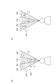
- the region 200 is a conical or pyramidal region.
- the region 200 extends in a fan shape as shown in FIG. 2(a).
- the fan shape may extend infinitely or may have a fixed size.
- the movement unit 15 sets the area 200 according to the position and direction in the virtual space set by the setting unit 13 . Specifically, the moving unit 15 sets the region 200 with the origin of the coordinate system after conversion corresponding to the position set by the setting unit 13 (that is, the reference position of the line of sight in the virtual space) as the vertex. Further, the moving unit 15 shifts the direction of the coordinate system after conversion corresponding to the direction set by the setting unit 13 (that is, the direction of the line of sight in the virtual space) to the direction of the center of the angle extending from the origin of the region 200.
- the area 200 is set as above.
- the moving unit 15 sets an area 200 corresponding to the range displayed on the display 10, that is, an area 200 corresponding to the field of view of the user, in the converted coordinate system. Note that the set area 200 does not have to match the range displayed on the display 10 . If the area 200 to be set matches the area displayed on the display 10 and the display 10 displays a rectangular shape, the area 200 to be set will expand in a pyramidal shape accordingly.
- the moving unit 15 determines the display information 100 included in the set area 200 .
- the display information 100 included in the area 200 may include the entire display information 100 , or may include the center axis preset for each display information 100 .
- the moving unit 15 sets the display information 100 included in the set area 200 as the display information 100 to be moved.
- the moving unit 15 moves the display information 100 to be moved in a preset direction.
- the preset direction is, for example, the direction toward the origin, which is the vertex of the area 200 (that is, the reference position of the line of sight in the virtual space). That is, in the display on the display 10, the display information 100 is moved closer to the user (attracted to the user).
- the display information 100 Since the display information 100 is moved toward the origin, it is performed by multiplying the coordinate value of the coordinate system after the display information 100 is converted by t (t is a positive value less than 1).
- the moving unit 15 restores and transforms the coordinate system of the virtual space to the original coordinate system.
- the restoration transformation itself of the coordinate system may be performed by a conventional method.
- the display unit 11 reflects the moved display information 100 on the display on the display 10 . Therefore, the user can see the display information 100 that is moved and displayed.
- the moving unit 15 may move the display information 100 at a preset constant speed. For example, a plurality of values of t are prepared, and the moving unit 15 sequentially calculates the coordinates after conversion, so that the display information 100 gradually moves in the display on the display 10 (when the user gets closer to the user). ). Alternatively, the user's operation to stop the movement may be received, and the movement may continue until the user's operation is received.
- the moving direction of the display information 100 may be a direction away from the origin, that is, a direction away from the user, instead of the direction toward the origin. Also, the moving direction of the display information 100 may be a direction other than the above. Further, the type of the trigger detected by the trigger detector 12 may be associated in advance with the moving direction of the display information 100, and the display information 100 may be moved in the direction corresponding to the detected trigger type. Moreover, the movement of the display information 100 in the coordinate system after conversion may be performed by a method other than the above.
- the moving unit 15 may move each piece of display information 100 to be moved at a speed corresponding to the position of the display information 100 in the area 200 described above.
- the moving unit 15 sets a partial area corresponding to an angle extending from the origin of the area 200 as shown in FIG. 2(a).
- the moving unit 15 sets a central partial area 210 extending from the origin of the area 200 and having an angle ⁇ , and a partial area 220 having an angle ⁇ ′ excluding the central angle ⁇ .
- the above angle ⁇ is, for example, 1 to 2°, which is the central vision angle of a human being.
- the above angle ⁇ ′ is, for example, 4 to 20°, which is the range of the effective visual field of humans.
- the moving unit 15 moves the display information 100 included in the partial area 210 at a speed v, and moves the display information 100 included in the partial area 220 at a speed sv.
- v and s are preset values, and 0 ⁇ s ⁇ 1. That is, the display information 100 included in the inner partial area 210 is moved quickly, and the display information 100 included in the outer partial area 210 is moved slowly. As a result, the display information 100 moves fast in the portion near the center of the display screen of the display 10, and the display information 100 moves slowly in the outer portion. By moving the display information 100 in this way, the movement of the display information 100 can be adapted to the user's visual sense.
- the moving unit 15 may set a band-shaped area 200 according to the position and direction in the virtual space set by the setting unit 13 and use it to move the display information 100 .
- the moving unit 15 sets a band-shaped region 200 that includes the origin of the coordinate system after conversion corresponding to the position set by the setting unit 13 at its end and extends in the direction set by the setting unit 13. do.
- the moving unit 15 moves the display information 100 included in the set area 200 in parallel with the direction set by the setting unit 13 .
- the entire coordinate system after conversion may be used as the region 200 described above.
- the display information 100 is arranged in the virtual space, and the line of sight in the virtual space is directed from left to right, that is, toward the display information 100 to be arranged.
- the line of sight in the virtual space moves by 6 DoF, as shown in FIG. 4A, the display information 100 behind is sometimes hidden by other display information 100 and cannot be seen or is difficult to see. In this case, since the distance is long, the appearance of the display information 100 in the back does not change much if the line of sight in the virtual space is slightly tilted.
- each piece of display information 100 approaches the reference position of the line of sight in the virtual space, as shown in FIG. 4(b).
- the movement of the display information 100 changes the distance u in the depth direction (direction of line of sight in the virtual space) as tu as described above, and does not change the height v of the display information 100 .
- the display information 100 may be moved so as to change the height v.
- FIG. 4(b) as a result of the movement of the display information, when the display information 100 approaches the reference position of the line of sight in the virtual space, if the line of sight in the virtual space is slightly moved, the display information 100 behind can also be confirmed. can do. That is, the display information 100 on the back can also be displayed on the display 10 so that the user can appropriately recognize it.
- the two pieces of display information 100 overlapping in the line-of-sight direction, indicated by double-headed arrows in FIG. 100 can be confirmed, and an operation such as selecting the display information 100 can be performed.
- the moving unit 15 may reduce or enlarge the display information 100 according to the movement of the display information 100 .
- the moving unit 15 stores the reduction ratio or enlargement ratio of the display information 100 according to the movement direction and movement amount, and moves the display information 100 according to the movement of the display information 100 based on the stored information. Shrink or expand.
- an arbitrary minimum size may be set in advance, and the display information 100 may be reduced to that size.
- an arbitrary maximum size may be set in advance, and the display information may be enlarged to that size.
- the reduction or enlargement of the display information 100 is performed, for example, so that the movement of the display information 100 does not make the display information 100 difficult to see.
- the above is the function of the display 10 according to the present embodiment.
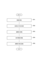
- the trigger detection unit 12 detects the trigger for moving the display information in the virtual space (S01).
- the setting unit 13 sets the position and direction in the virtual space used for moving the display information in the virtual space (S02).
- the transformation unit 14 transforms the coordinate system of the virtual space based on the position and direction in the virtual space set by the setting unit 13 (S03).
- the display information 100 included in the area corresponding to the position and direction in the virtual space set by the setting unit 13 is moved by the moving unit 15 in the converted coordinate system (S04).
- the moving unit 15 restores and transforms the coordinate system of the virtual space to the original coordinate system (S05).
- the movement of the display information 100 by the above processing is reflected in the display by the display section 11 on the display 10 .
- the above is the processing executed by the display 10 according to the present embodiment.
- the display information 100 included in the area 200 is moved according to the position and direction in the virtual space used for moving the display information 100 . Therefore, it is possible to easily move the display information 100, which could not be easily moved by the conventional method, for example, by specifying the display information by the line of sight and the user's operation. Also, the coordinate system of the virtual space is transformed when the display information 100 is moved. Therefore, it is possible to move the display information 100 after converting the display information into a coordinate system that is easy to move. For example, the display information 100 can be easily moved by multiplying the coordinate values by t as described above. As described above, according to the present embodiment, it is possible to easily and appropriately move the display information in the display using the virtual space. As a result, for example, by making the display information 100 appear near the user as described above, it is possible to improve visibility and ease of selection.
- the setting unit 13 may set the position and direction of the line of sight in the virtual space to the position and direction in the virtual space used for moving the display information 100 in the virtual space. . According to this configuration, it is possible to appropriately move the display information 100 according to the position and direction of the line of sight in the virtual space.
- the position and direction in the virtual space used to move the display information 100 in the virtual space may be any position and direction other than the position and direction of the line of sight in the virtual space.
- the moving unit 15 may move the display information 100 included in the fan-shaped or strip-shaped area 200 according to the position and direction in the virtual space set by the setting unit 13. good. According to this configuration, the display information 100 to be moved can be made appropriate.
- the region 200 is not limited to the above shape and may have any shape.
- the moving unit 15 may move each piece of display information 100 to be moved at a speed corresponding to the position of the display information 100 in the area 200 .
- the display information 100 can be moved according to the user's visual sense.
- the moving unit 15 may reduce or enlarge the display information 100 according to the movement of the display information 100 .
- this configuration for example, it is possible to prevent the display information 100 from becoming difficult to see due to the movement of the display information 100 .
- the display information 100 may not be reduced or enlarged.
- the display control device has been described as the display 10 having a display function, but it does not necessarily have to have a display function.
- the display control device is a device (system) that is connected to a display that displays display information arranged in the virtual space according to the line of sight of the virtual space (that is, includes the display unit 11) and that controls display on the display. , the trigger detection unit 12, the setting unit 13, the conversion unit 14, and the movement unit 15 described above.
- some or all of the functional units 12 to 15 described above may be provided in a device such as a server capable of transmitting and receiving information to and from the display.
- each functional unit 12 to 15 provided in a device such as a server may transmit and receive input/output information to/from the display.
- each functional block may be implemented using one device that is physically or logically coupled, or directly or indirectly using two or more devices that are physically or logically separated (e.g. , wired, wireless, etc.) and may be implemented using these multiple devices.
- a functional block may be implemented by combining software in the one device or the plurality of devices.
- Functions include judging, determining, determining, calculating, calculating, processing, deriving, investigating, searching, checking, receiving, transmitting, outputting, accessing, resolving, selecting, choosing, establishing, comparing, assuming, expecting, assuming, Broadcasting, notifying, communicating, forwarding, configuring, reconfiguring, allocating, mapping, assigning, etc. can't
- a functional block (component) responsible for transmission is called a transmitting unit or transmitter.
- the implementation method is not particularly limited.
- the display 10 in one embodiment of the present disclosure may function as a computer that performs information processing of the present disclosure.
- FIG. 6 is a diagram illustrating an example of a hardware configuration of display 10 according to an embodiment of the present disclosure.
- the display 10 described above may be physically configured as a computer device including a processor 1001, a memory 1002, a storage 1003, a communication device 1004, an input device 1005, an output device 1006, a bus 1007, and the like.
- the term "apparatus” can be read as a circuit, device, unit, or the like.
- the hardware configuration of the display 10 may be configured to include one or more of each device shown in the drawing, or may be configured without some of the devices.
- Each function of the display 10 is performed by loading predetermined software (programs) on hardware such as the processor 1001 and the memory 1002 so that the processor 1001 performs calculations, controls communication by the communication device 1004, controls the communication by the memory 1002 and It is realized by controlling at least one of data reading and writing in the storage 1003 .
- the processor 1001 for example, operates an operating system and controls the entire computer.
- the processor 1001 may be configured by a central processing unit (CPU) including an interface with peripheral devices, a control device, an arithmetic device, registers, and the like.
- CPU central processing unit
- each function of display 10 described above may be implemented by processor 1001 .
- the processor 1001 reads programs (program codes), software modules, data, etc. from at least one of the storage 1003 and the communication device 1004 to the memory 1002, and executes various processes according to them.
- programs program codes
- software modules software modules
- data etc.
- the program a program that causes a computer to execute at least part of the operations described in the above embodiments is used.
- each function of display 10 may be implemented by a control program stored in memory 1002 and running on processor 1001 .
- FIG. Processor 1001 may be implemented by one or more chips.
- the program may be transmitted from a network via an electric communication line.
- the memory 1002 is a computer-readable recording medium, and is composed of at least one of, for example, ROM (Read Only Memory), EPROM (Erasable Programmable ROM), EEPROM (Electrically Erasable Programmable ROM), RAM (Random Access Memory), etc. may be
- ROM Read Only Memory
- EPROM Erasable Programmable ROM
- EEPROM Electrical Erasable Programmable ROM
- RAM Random Access Memory
- the memory 1002 may also be called a register, cache, main memory (main storage device), or the like.
- the memory 1002 can store executable programs (program code), software modules, etc. for performing information processing according to an embodiment of the present disclosure.
- the storage 1003 is a computer-readable recording medium, for example, an optical disc such as a CD-ROM (Compact Disc ROM), a hard disk drive, a flexible disc, a magneto-optical disc (for example, a compact disc, a digital versatile disc, a Blu-ray disk), smart card, flash memory (eg, card, stick, key drive), floppy disk, magnetic strip, and/or the like.
- Storage 1003 may also be called an auxiliary storage device.
- the storage medium included in display 10 may be, for example, a database, server, or other suitable medium including at least one of memory 1002 and storage 1003 .
- the communication device 1004 is hardware (transmitting/receiving device) for communicating between computers via at least one of a wired network and a wireless network, and is also called a network device, a network controller, a network card, a communication module, or the like.
- the input device 1005 is an input device (for example, keyboard, mouse, microphone, switch, button, sensor, etc.) that receives input from the outside.
- the output device 1006 is an output device (eg, display, speaker, LED lamp, etc.) that outputs to the outside. Note that the input device 1005 and the output device 1006 may be integrated (for example, a touch panel).
- Each device such as the processor 1001 and the memory 1002 is connected by a bus 1007 for communicating information.
- the bus 1007 may be configured using a single bus, or may be configured using different buses between devices.
- the display 10 includes hardware such as a microprocessor, a digital signal processor (DSP), an ASIC (Application Specific Integrated Circuit), a PLD (Programmable Logic Device), and an FPGA (Field Programmable Gate Array).
- DSP digital signal processor
- ASIC Application Specific Integrated Circuit
- PLD Physical Location Deposition
- FPGA Field Programmable Gate Array
- a part or all of each functional block may be implemented by the hardware.
- processor 1001 may be implemented using at least one of these pieces of hardware.
- Input/output information may be stored in a specific location (for example, memory) or managed using a management table. Input/output information and the like can be overwritten, updated, or appended. The output information and the like may be deleted. The entered information and the like may be transmitted to another device.
- the determination may be made by a value represented by one bit (0 or 1), by a true/false value (Boolean: true or false), or by numerical comparison (for example, a predetermined value).
- notification of predetermined information is not limited to being performed explicitly, but may be performed implicitly (for example, not notifying the predetermined information). good too.
- Software whether referred to as software, firmware, middleware, microcode, hardware description language or otherwise, includes instructions, instruction sets, code, code segments, program code, programs, subprograms, and software modules. , applications, software applications, software packages, routines, subroutines, objects, executables, threads of execution, procedures, functions, and the like.
- software, instructions, information, etc. may be transmitted and received via a transmission medium.
- the software uses at least one of wired technology (coaxial cable, fiber optic cable, twisted pair, digital subscriber line (DSL), etc.) and wireless technology (infrared, microwave, etc.) to website, Wired and/or wireless technologies are included within the definition of transmission medium when sent from a server or other remote source.
- wired technology coaxial cable, fiber optic cable, twisted pair, digital subscriber line (DSL), etc.
- wireless technology infrared, microwave, etc.
- system and “network” used in this disclosure are used interchangeably.
- information, parameters, etc. described in the present disclosure may be expressed using absolute values, may be expressed using relative values from a predetermined value, or may be expressed using other corresponding information. may be represented.
- determining and “determining” used in this disclosure may encompass a wide variety of actions.
- “Judgement” and “determination” are, for example, judging, calculating, computing, processing, deriving, investigating, looking up, searching, inquiring (eg, lookup in a table, database, or other data structure), ascertaining as “judged” or “determined”, and the like.
- "judgment” and “determination” are used for receiving (e.g., receiving information), transmitting (e.g., transmitting information), input, output, access (accessing) (for example, accessing data in memory) may include deeming that a "judgment” or “decision” has been made.
- judgment and “decision” are considered to be “judgment” and “decision” by resolving, selecting, choosing, establishing, comparing, etc. can contain.
- judgment and “decision” may include considering that some action is “judgment” and “decision”.
- judgment (decision) may be read as “assuming”, “expecting”, “considering”, or the like.
- connection means any direct or indirect connection or coupling between two or more elements, It can include the presence of one or more intermediate elements between two elements being “connected” or “coupled.” Couplings or connections between elements may be physical, logical, or a combination thereof. For example, “connection” may be read as "access”.
- two elements are defined using at least one of one or more wires, cables, and printed electrical connections and, as some non-limiting and non-exhaustive examples, in the radio frequency domain. , electromagnetic energy having wavelengths in the microwave and optical (both visible and invisible) regions, and the like.
- any reference to elements using the "first,” “second,” etc. designations used in this disclosure does not generally limit the quantity or order of those elements. These designations may be used in this disclosure as a convenient method of distinguishing between two or more elements. Thus, reference to a first and second element does not imply that only two elements can be employed or that the first element must precede the second element in any way.
- a and B are different may mean “A and B are different from each other.”
- the term may also mean that "A and B are different from C”.
- Terms such as “separate,” “coupled,” etc. may also be interpreted in the same manner as “different.”
Landscapes
- Engineering & Computer Science (AREA)
- Theoretical Computer Science (AREA)
- General Engineering & Computer Science (AREA)
- Physics & Mathematics (AREA)
- General Physics & Mathematics (AREA)
- Human Computer Interaction (AREA)
- Computer Hardware Design (AREA)
- Computer Graphics (AREA)
- Software Systems (AREA)
- User Interface Of Digital Computer (AREA)
Priority Applications (1)
| Application Number | Priority Date | Filing Date | Title |
|---|---|---|---|
| JP2023543736A JP7608622B2 (ja) | 2021-08-26 | 2022-07-07 | 表示制御装置 |
Applications Claiming Priority (2)
| Application Number | Priority Date | Filing Date | Title |
|---|---|---|---|
| JP2021137986 | 2021-08-26 | ||
| JP2021-137986 | 2021-08-26 |
Publications (1)
| Publication Number | Publication Date |
|---|---|
| WO2023026700A1 true WO2023026700A1 (ja) | 2023-03-02 |
Family
ID=85322725
Family Applications (1)
| Application Number | Title | Priority Date | Filing Date |
|---|---|---|---|
| PCT/JP2022/026986 Ceased WO2023026700A1 (ja) | 2021-08-26 | 2022-07-07 | 表示制御装置 |
Country Status (2)
| Country | Link |
|---|---|
| JP (1) | JP7608622B2 (https=) |
| WO (1) | WO2023026700A1 (https=) |
Citations (6)
| Publication number | Priority date | Publication date | Assignee | Title |
|---|---|---|---|---|
| JP2011198150A (ja) * | 2010-03-19 | 2011-10-06 | Fujifilm Corp | ヘッドマウント型拡張現実映像提示装置及びその仮想表示物操作方法 |
| JP2017027206A (ja) * | 2015-07-17 | 2017-02-02 | キヤノン株式会社 | 情報処理装置、仮想オブジェクトの操作方法、コンピュータプログラム、及び記憶媒体 |
| CN108771866A (zh) * | 2018-05-29 | 2018-11-09 | 网易(杭州)网络有限公司 | 虚拟现实中的虚拟对象控制方法及装置 |
| US20190362557A1 (en) * | 2018-05-22 | 2019-11-28 | Magic Leap, Inc. | Transmodal input fusion for a wearable system |
| WO2020036898A1 (en) * | 2018-08-13 | 2020-02-20 | Magic Leap, Inc. | A cross reality system |
| US20210084278A1 (en) * | 2017-05-18 | 2021-03-18 | Pcms Holdings, Inc. | System and method for distributing and rendering content as spherical video and 3d asset combination |
-
2022
- 2022-07-07 WO PCT/JP2022/026986 patent/WO2023026700A1/ja not_active Ceased
- 2022-07-07 JP JP2023543736A patent/JP7608622B2/ja active Active
Patent Citations (6)
| Publication number | Priority date | Publication date | Assignee | Title |
|---|---|---|---|---|
| JP2011198150A (ja) * | 2010-03-19 | 2011-10-06 | Fujifilm Corp | ヘッドマウント型拡張現実映像提示装置及びその仮想表示物操作方法 |
| JP2017027206A (ja) * | 2015-07-17 | 2017-02-02 | キヤノン株式会社 | 情報処理装置、仮想オブジェクトの操作方法、コンピュータプログラム、及び記憶媒体 |
| US20210084278A1 (en) * | 2017-05-18 | 2021-03-18 | Pcms Holdings, Inc. | System and method for distributing and rendering content as spherical video and 3d asset combination |
| US20190362557A1 (en) * | 2018-05-22 | 2019-11-28 | Magic Leap, Inc. | Transmodal input fusion for a wearable system |
| CN108771866A (zh) * | 2018-05-29 | 2018-11-09 | 网易(杭州)网络有限公司 | 虚拟现实中的虚拟对象控制方法及装置 |
| WO2020036898A1 (en) * | 2018-08-13 | 2020-02-20 | Magic Leap, Inc. | A cross reality system |
Also Published As
| Publication number | Publication date |
|---|---|
| JPWO2023026700A1 (https=) | 2023-03-02 |
| JP7608622B2 (ja) | 2025-01-06 |
Similar Documents
| Publication | Publication Date | Title |
|---|---|---|
| KR102918416B1 (ko) | 증강 현실 서비스를 제공하기 위한 전자 장치 및 그의 동작 방법 | |
| KR20190101827A (ko) | 디스플레이를 통해 표시된 제 1 콘텐트에 대해 제 2 콘텐트를 외부 객체의 움직임에 따라 제공하기 위한 전자 장치 및 그의 동작 방법 | |
| US12585330B2 (en) | Eye tracking based selection of a user interface (UI) element based on targeting criteria | |
| US12322048B2 (en) | Connecting spatially distinct settings | |
| JP7779062B2 (ja) | 情報処理装置、情報処理システム、およびプログラム | |
| JP7603827B2 (ja) | 表示制御装置 | |
| WO2023026700A1 (ja) | 表示制御装置 | |
| JP7733815B2 (ja) | 仮想空間提供装置 | |
| JP7777039B2 (ja) | 情報処理装置 | |
| JP7583948B2 (ja) | 表示制御装置 | |
| US12530843B2 (en) | Virtual space presentation device | |
| JP7384951B2 (ja) | 遮られた物理的オブジェクトの位置を示すこと | |
| US20220206736A1 (en) | Information processing apparatus, information processing system, and non-transitory computer readable medium | |
| WO2022201739A1 (ja) | 表示制御装置 | |
| JP7576183B2 (ja) | 仮想空間提供装置 | |
| JP7829680B2 (ja) | 表示装置 | |
| WO2022190735A1 (ja) | 表示制御装置 | |
| JP2022150657A (ja) | 制御装置、表示システム、および、プログラム | |
| JP7717628B2 (ja) | 情報処理装置 | |
| JP7564371B2 (ja) | 仮想空間提供装置 | |
| JP7562836B2 (ja) | 表示制御装置 | |
| WO2022201936A1 (ja) | 表示制御装置 | |
| US12198267B1 (en) | Generating a shadow based on a spherical gaussian lobe | |
| US20230386093A1 (en) | Changing Locked Modes Associated with Display of Computer-Generated Content | |
| JP2024089241A (ja) | 表示制御装置 |
Legal Events
| Date | Code | Title | Description |
|---|---|---|---|
| 121 | Ep: the epo has been informed by wipo that ep was designated in this application |
Ref document number: 22860991 Country of ref document: EP Kind code of ref document: A1 |
|
| WWE | Wipo information: entry into national phase |
Ref document number: 2023543736 Country of ref document: JP |
|
| NENP | Non-entry into the national phase |
Ref country code: DE |
|
| 122 | Ep: pct application non-entry in european phase |
Ref document number: 22860991 Country of ref document: EP Kind code of ref document: A1 |