WO2023026700A1 - Display control apparatus - Google Patents
Display control apparatus Download PDFInfo
- Publication number
- WO2023026700A1 WO2023026700A1 PCT/JP2022/026986 JP2022026986W WO2023026700A1 WO 2023026700 A1 WO2023026700 A1 WO 2023026700A1 JP 2022026986 W JP2022026986 W JP 2022026986W WO 2023026700 A1 WO2023026700 A1 WO 2023026700A1
- Authority
- WO
- WIPO (PCT)
- Prior art keywords
- display
- virtual space
- display information
- unit
- information
- Prior art date
Links
- 238000006243 chemical reaction Methods 0.000 claims abstract description 22
- 238000001514 detection method Methods 0.000 claims abstract description 17
- 230000001131 transforming effect Effects 0.000 claims description 2
- 230000006870 function Effects 0.000 description 27
- 238000000034 method Methods 0.000 description 23
- 238000004891 communication Methods 0.000 description 12
- 238000012545 processing Methods 0.000 description 10
- 238000007796 conventional method Methods 0.000 description 7
- 238000010586 diagram Methods 0.000 description 5
- 230000010365 information processing Effects 0.000 description 5
- 230000009466 transformation Effects 0.000 description 5
- 239000011521 glass Substances 0.000 description 4
- 230000008569 process Effects 0.000 description 4
- 238000013459 approach Methods 0.000 description 3
- 230000005540 biological transmission Effects 0.000 description 3
- 230000008859 change Effects 0.000 description 3
- 238000005516 engineering process Methods 0.000 description 3
- 230000009467 reduction Effects 0.000 description 3
- 239000000344 soap Substances 0.000 description 3
- 230000000007 visual effect Effects 0.000 description 3
- 230000001133 acceleration Effects 0.000 description 2
- 230000009471 action Effects 0.000 description 2
- 230000008878 coupling Effects 0.000 description 2
- 238000010168 coupling process Methods 0.000 description 2
- 238000005859 coupling reaction Methods 0.000 description 2
- 230000003287 optical effect Effects 0.000 description 2
- 230000003190 augmentative effect Effects 0.000 description 1
- 230000000694 effects Effects 0.000 description 1
- 239000000835 fiber Substances 0.000 description 1
- 238000007667 floating Methods 0.000 description 1
- 238000013507 mapping Methods 0.000 description 1
- 238000012986 modification Methods 0.000 description 1
- 230000004048 modification Effects 0.000 description 1
- 230000002093 peripheral effect Effects 0.000 description 1
- 239000004984 smart glass Substances 0.000 description 1
- 238000013519 translation Methods 0.000 description 1
Images


Classifications
-
- G—PHYSICS
- G06—COMPUTING; CALCULATING OR COUNTING
- G06F—ELECTRIC DIGITAL DATA PROCESSING
- G06F3/00—Input arrangements for transferring data to be processed into a form capable of being handled by the computer; Output arrangements for transferring data from processing unit to output unit, e.g. interface arrangements
- G06F3/01—Input arrangements or combined input and output arrangements for interaction between user and computer
- G06F3/048—Interaction techniques based on graphical user interfaces [GUI]
- G06F3/0481—Interaction techniques based on graphical user interfaces [GUI] based on specific properties of the displayed interaction object or a metaphor-based environment, e.g. interaction with desktop elements like windows or icons, or assisted by a cursor's changing behaviour or appearance
- G06F3/04815—Interaction with a metaphor-based environment or interaction object displayed as three-dimensional, e.g. changing the user viewpoint with respect to the environment or object
-
- G—PHYSICS
- G06—COMPUTING; CALCULATING OR COUNTING
- G06F—ELECTRIC DIGITAL DATA PROCESSING
- G06F3/00—Input arrangements for transferring data to be processed into a form capable of being handled by the computer; Output arrangements for transferring data from processing unit to output unit, e.g. interface arrangements
- G06F3/01—Input arrangements or combined input and output arrangements for interaction between user and computer
- G06F3/048—Interaction techniques based on graphical user interfaces [GUI]
- G06F3/0484—Interaction techniques based on graphical user interfaces [GUI] for the control of specific functions or operations, e.g. selecting or manipulating an object, an image or a displayed text element, setting a parameter value or selecting a range
- G06F3/04842—Selection of displayed objects or displayed text elements
-
- G—PHYSICS
- G06—COMPUTING; CALCULATING OR COUNTING
- G06T—IMAGE DATA PROCESSING OR GENERATION, IN GENERAL
- G06T19/00—Manipulating 3D models or images for computer graphics
-
- G—PHYSICS
- G09—EDUCATION; CRYPTOGRAPHY; DISPLAY; ADVERTISING; SEALS
- G09G—ARRANGEMENTS OR CIRCUITS FOR CONTROL OF INDICATING DEVICES USING STATIC MEANS TO PRESENT VARIABLE INFORMATION
- G09G5/00—Control arrangements or circuits for visual indicators common to cathode-ray tube indicators and other visual indicators
Definitions
- the present invention relates to a display control device that controls display on a display.
- Japanese Patent Laid-Open No. 2002-200001 discloses that display information in a virtual space is designated and moved by a line of sight in the virtual space.
- Patent Document 1 With the method of designating display information to be individually moved according to the line of sight, as shown in Patent Document 1, it may be difficult to easily and appropriately move the display information. For example, in the above method, it is difficult or impossible to specify and move display information that is hidden behind other display information and is not displayed. A similar problem also arises in a method of designating display information to be individually moved by a user's operation, instead of designation by line of sight.
- An embodiment of the present invention has been made in view of the above, and an object thereof is to provide a display control device capable of easily and appropriately moving display information in a display using a virtual space.
- a display control device is a display control device that controls display on a display that displays display information arranged in a virtual space according to the line of sight in the virtual space, and that displays the display information in the virtual space.
- a trigger detection unit that detects a trigger for movement
- a setting unit that sets the position and direction in the virtual space used to move the display information in the virtual space
- a transformation unit that transforms the coordinate system of the virtual space based on the set position and direction in the virtual space
- a moving unit that moves the display information included in the corresponding area to restore and transform the coordinate system of the virtual space to the original coordinate system.
- the display information included in the area corresponding to the position and direction in the virtual space used for moving the display information is moved. Therefore, it is possible to easily move display information that could not be easily moved by the conventional method. Also, the coordinate system of the virtual space is transformed when the display information is moved. Therefore, the display information can be moved after being converted into a coordinate system that facilitates movement of the display information. As described above, according to the display control device according to the embodiment of the present invention, it is possible to easily and appropriately move the display information in the display using the virtual space.
- FIG. 4 is a diagram schematically showing examples of display information arranged in a virtual space and areas used for movement
- FIG. 10 is a diagram schematically showing another example of display information arranged in a virtual space and areas used for movement
- FIG. 4 is a diagram schematically showing an example of movement of display information in virtual space
- 4 is a flow chart showing processing executed by a display that is a display control device according to an embodiment of the present invention
- FIG. 1 shows the functional configuration of a display 10, which is a display control device according to this embodiment.
- the display 10 displays display information arranged in a virtual space (for example, a virtual three-dimensional space) according to the line of sight in the virtual space.
- the display information is, for example, contents such as characters, images, and moving images.
- the display information may be anything other than the above as long as it can be arranged in the virtual space and displayed according to the line of sight in the virtual space.
- the display 10 is a display that displays virtual content (display information) by XR such as AR (Augmented Reality), MR (Mixed Reality) or VR (Virtual Reality).
- the display 10 may be a transmissive display worn over the user's eye.
- the display 10 may be a glasses-type head-mounted display, that is, see-through glasses (smart glasses, XR glasses).
- the display 10 is assumed to be worn on the user's eye, ie, on the user's head. However, the display 10 need not be worn by the user.
- the display 10 displays the display information of the area visible in the direction of the line of sight in the virtual space from the reference position of the line of sight (the starting point of the line of sight) in the virtual space.
- the line of sight in the virtual space includes the reference position of the line of sight in the virtual space and the direction of the line of sight in the virtual space.
- the display 10 can display by moving the line of sight in the virtual space. By moving the line of sight in the virtual space, the display information seen in the virtual space changes, and the display on the display 10 also changes.
- the line of sight of the display 10 in the virtual space may be based on the position or orientation of the display 10 in the real space. Therefore, the display 10 may be provided with a sensor that detects the movement (ie, positional variation) and orientation (ie, attitude) of the display 10 itself. For example, an acceleration sensor that detects acceleration and a gyro sensor that detects angular velocity may be provided. The display 10 may detect the movement and orientation of the display 10 itself using these sensors, and move the line of sight in the virtual space according to the detected movement and orientation. That is, the line of sight may be moved according to the direction of the head (face) of the user wearing the display 10 . However, the movement of the line of sight in the virtual space may be performed according to the detection of the position or orientation by sensors other than those described above.
- the movement of the line of sight in the virtual space may be performed by the user's operation on the display 10 instead of by the sensor as described above.
- the display on the display 10 using the line of sight in the virtual space may be performed in the same manner as the conventional display by AR, MR, VR, or the like.
- the holding and processing of information regarding the virtual space may be performed in the display 10 or may be performed in a cloud or the like connected to the display 10 .
- the movement of the line of sight in the virtual space is performed according to a preset method. For example, movement of the line of sight in the virtual space is performed with a predetermined degree of freedom.
- the preset degree of freedom is, for example, 6 DoF (Degree of Freedom).
- the reference position of the line of sight in the virtual space can be moved in the three axial directions of the virtual space's X, Y, and Z axes.
- the direction of the line of sight in the virtual space can be rotated around three axes of the X, Y, and Z axes of the virtual space. Therefore, when the user wearing the display 10 moves his/her head, it is possible to see display information according to the movement.
- the line of sight in the virtual space may be moved by a degree of freedom other than the above and by a method other than the above.
- an operation related to display for example, a user's operation on display information may be performed.
- the display 10 receives a user's operation and reflects the operation on the display. For example, operations such as generation, movement, enlargement and reduction of display information in the virtual space, and character input for display information may be performed.
- the operation may be performed using, for example, an information processing device such as a smart phone carried by the user wearing the display 10 . In that case, the display 10 and the smartphone are connected in advance so that information can be transmitted and received.
- the operation may be performed by a dedicated controller attached to the head-mounted display.
- the operation may be performed by a user's gesture.
- the part of the user that makes the gesture is, for example, the hand. That is, an operation using a hand tracking gesture may be performed.
- an operation may be performed by a gesture using a part other than the hand.
- a camera is provided so as to capture an image of the part where the gesture is performed, and the gesture is determined based on the moving image captured by the camera.
- the operation may be performed in any manner other than the above.
- the above display and operation on the display 10 may be performed in the same manner as in the conventional method.
- Display information commonly arranged in a common virtual space may be used for the display on the display 10 and the display on another display. That is, the virtual space and display information may be shared among multiple displays. The multiple displays with which the virtual space and display information are shared are preset. The line of sight of the virtual space in the display on the display 10 and in the display on the other display may be independent for each display. If the lines of sight on the displays are different, for example, different displays according to the respective lines of sight are performed on each display.
- the virtual space may correspond to the real space. Accordingly, for example, by directing the display 10 to a specific position in the physical space, it is possible to display the display information arranged at the position in the virtual space corresponding to the specific position.
- the virtual space and display information are shared among the multiple displays, and the virtual space is associated with the real space, enabling asynchronous communication among the users of the multiple displays. For example, after a user arranges display information generated by himself/herself in a virtual space, another user directs the display to a position in the real space corresponding to the arrangement position of the display information so that the display information can be transferred to the other user. can be displayed on the display.
- the above display information is, for example, a message (words, text) to another user or a three-dimensional video.
- the display information may be a display of a soap bubble floating in the virtual space, and when the soap bubble is broken by a user's operation or the like, the message and content such as the three-dimensional video may be referred to.
- the content may be displayed in space in a state where the content is placed in a soap bubble.
- the display 10 a conventional display having the above functions can be used.
- the display 10 may have a communication function.
- the communication function of the display 10 may be used to share the virtual space and display information described above and to realize the functions according to the present embodiment.
- some of the above-described functions of the display 10 and functions according to the present embodiment described later are an information processing device (such as a smartphone or a PC (personal computer)) connected to a display device (such as the above-described see-through glasses). may have. That is, the display 10 according to the present embodiment may be realized by including the display device and the information processing device.
- the display 10 includes a display section 11 , a trigger detection section 12 , a setting section 13 , a conversion section 14 and a movement section 15 .
- the display 10 may have functions other than those described above that conventional display devices, such as conventional see-through glasses, have.
- the functions of the display 10 described below are for moving the display information arranged in the virtual space. For example, when the display information is away from the reference position of the line of sight in the virtual space, the display information is displayed in a small size. When the display information is moved so as to approach the reference position of the line of sight, the display information is displayed in a large size so that the user can see it clearly.
- a hand tracking gesture it is also conceivable to use a hand tracking gesture, a dedicated controller, or the like to designate display information that moves when the user touches the display information with his or her hand.
- this method limits the display information that can be specified within reach. For example, the user himself/herself needs to move when trying to move the displayed information in the distance.
- a method of designating display information to be moved by a pointer beam is also conceivable.
- this method requires a delicate operation, especially when specifying distant display information.
- the function according to the present embodiment solves the above problem and allows the displayed information to be moved easily and appropriately.
- the function according to the present embodiment enables the user to operate display information that is out of reach with the user wearing the display 10 without any burden on the user.
- display information related to display on the display 10 may be performed by functions other than the functions according to the present embodiment, in addition to the functions according to the present embodiment.
- display information may be moved in any of the ways described above.
- the display unit 11 is a functional unit that displays on the display 10.
- the display unit 11 receives and displays display information to be displayed on the display 10 .
- the display unit 11 may input display information stored in the display 10, or receive and input display information from the outside.
- the display unit 11 displays the display information arranged in the virtual space according to the line of sight in the virtual space.
- the display unit 11 may share the virtual space and display information with other displays.
- the sharing of the virtual space and the display information is performed, for example, by transmitting/receiving the information indicating the position of the display information and the virtual space where the display information is arranged to/from another display.
- sharing of virtual space and display information may be performed via a server with which each display can communicate, instead of direct exchange between displays.
- the virtual space and the display information may be shared between the displays by a method other than the above.
- the above function of the display unit 11 may be the same as the conventional function. Further, the display by the display unit 11 is controlled by the moving unit 15 as will be described later.
- the opportunity detection unit 12 is a functional unit that detects an opportunity (trigger) for moving display information in the virtual space.
- the trigger detection unit 12 stores in advance the user's operation that serves as the trigger. It is assumed that the trigger detection unit 12 has detected the above-described trigger when the user's operation is received and the received user's operation is stored in advance.
- the user's operation that triggers the above is, for example, pressing a button, gesturing, or inputting a specific command by voice. Note that the trigger may be a user's operation other than the above, or may be other than the user's operation.
- the trigger detection unit 12 detects the trigger, the trigger detection unit 12 notifies the setting unit 13 to that effect.
- the setting unit 13 is a functional unit that sets the position and direction in the virtual space used to move the display information in the virtual space.
- the setting unit 13 may set the position and direction of the line of sight in the virtual space to the position and direction in the virtual space used for moving the display information in the virtual space.
- the position and direction that are set are the criteria for determining the displayed information to move.
- the reference position and direction of the line of sight in the virtual space are used in advance as the position and direction used for movement.
- the setting unit 13 receives notification of the detection of the trigger from the trigger detection unit 12 .
- the setting unit 13 acquires information indicating the reference position and direction of the line of sight in the virtual space held by the display unit 11, and moves the reference position and direction of the line of sight according to the movement of the display information.
- the information indicating the reference position of the line of sight in the virtual space is, for example, coordinates in the coordinate system (absolute coordinate system) of the virtual space.
- the information indicating the direction of the line of sight in the virtual space is, for example, a vector in the coordinate system of the virtual space.
- the coordinate system of the virtual space is, for example, an orthogonal coordinate system (X, Y, Z).
- the setting unit 13 outputs information indicating the set position and direction in the virtual space used for movement to the conversion unit 14 .
- the position and direction in the virtual space used for moving the display information need not be the position and direction of the line of sight in the virtual space, and may be other positions and directions. Further, the position and direction in the virtual space used to move the display information need not be set according to the previously stored setting criteria as described above. may
- the conversion unit 14 is a functional unit that converts the coordinate system of the virtual space based on the position and direction in the virtual space set by the setting unit 13 when the trigger detection unit 12 detects the trigger.
- the conversion unit 14 receives information from the setting unit 13 indicating the position and direction in the virtual space used for movement.
- the conversion unit 14 converts the coordinate axes of the virtual space so that the position indicated by the input information is the origin, and the direction indicated by the information is the preset direction extending from the origin.
- the reference position and direction of the line of sight in the virtual space are the position and direction used for movement, the reference position of the line of sight is converted into a coordinate system having the origin.
- the transformation unit 14 transforms the coordinate system (X, Y, Z) of the virtual space corresponding to the real space into the coordinate system (X', Y', Z') of the user's viewpoint (temporary coordinate system).
- the coordinate system after conversion may be an orthogonal coordinate system as described above, or may be another coordinate system (for example, a spherical coordinate system).
- the conversion unit 14 also calculates the position (coordinates) of the display information in the coordinate system (X', Y', Z') after conversion.
- the conversion unit 14 outputs information indicating the coordinate system (X′, Y′, Z′) after conversion to the moving unit 15 .
- the moving unit 15 moves the display information included in the area corresponding to the position and direction in the virtual space set by the setting unit 13 in the coordinate system transformed by the transforming unit 14, thereby moving the coordinate system of the virtual space.
- This is a functional unit that restores and transforms to the original coordinate system.
- the moving unit 15 may move the display information included in the fan-shaped or belt-shaped area according to the position and direction in the virtual space set by the setting unit 13 .
- the moving unit 15 may move each piece of display information to be moved at a speed corresponding to the position of the display information in the above area.
- the moving unit 15 may reduce or enlarge the display information according to the movement of the display information.
- the moving unit 15 performs, for example, the following processing.
- the moving unit 15 receives information indicating the coordinate system (X', Y', Z') after conversion from the converting unit 14.
- the moving unit 15 sets a region (range) used for moving the display information in the converted coordinate system.
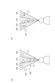
- the region 200 is a conical or pyramidal region.
- the region 200 extends in a fan shape as shown in FIG. 2(a).
- the fan shape may extend infinitely or may have a fixed size.
- the movement unit 15 sets the area 200 according to the position and direction in the virtual space set by the setting unit 13 . Specifically, the moving unit 15 sets the region 200 with the origin of the coordinate system after conversion corresponding to the position set by the setting unit 13 (that is, the reference position of the line of sight in the virtual space) as the vertex. Further, the moving unit 15 shifts the direction of the coordinate system after conversion corresponding to the direction set by the setting unit 13 (that is, the direction of the line of sight in the virtual space) to the direction of the center of the angle extending from the origin of the region 200.
- the area 200 is set as above.
- the moving unit 15 sets an area 200 corresponding to the range displayed on the display 10, that is, an area 200 corresponding to the field of view of the user, in the converted coordinate system. Note that the set area 200 does not have to match the range displayed on the display 10 . If the area 200 to be set matches the area displayed on the display 10 and the display 10 displays a rectangular shape, the area 200 to be set will expand in a pyramidal shape accordingly.
- the moving unit 15 determines the display information 100 included in the set area 200 .
- the display information 100 included in the area 200 may include the entire display information 100 , or may include the center axis preset for each display information 100 .
- the moving unit 15 sets the display information 100 included in the set area 200 as the display information 100 to be moved.
- the moving unit 15 moves the display information 100 to be moved in a preset direction.
- the preset direction is, for example, the direction toward the origin, which is the vertex of the area 200 (that is, the reference position of the line of sight in the virtual space). That is, in the display on the display 10, the display information 100 is moved closer to the user (attracted to the user).
- the display information 100 Since the display information 100 is moved toward the origin, it is performed by multiplying the coordinate value of the coordinate system after the display information 100 is converted by t (t is a positive value less than 1).
- the moving unit 15 restores and transforms the coordinate system of the virtual space to the original coordinate system.
- the restoration transformation itself of the coordinate system may be performed by a conventional method.
- the display unit 11 reflects the moved display information 100 on the display on the display 10 . Therefore, the user can see the display information 100 that is moved and displayed.
- the moving unit 15 may move the display information 100 at a preset constant speed. For example, a plurality of values of t are prepared, and the moving unit 15 sequentially calculates the coordinates after conversion, so that the display information 100 gradually moves in the display on the display 10 (when the user gets closer to the user). ). Alternatively, the user's operation to stop the movement may be received, and the movement may continue until the user's operation is received.
- the moving direction of the display information 100 may be a direction away from the origin, that is, a direction away from the user, instead of the direction toward the origin. Also, the moving direction of the display information 100 may be a direction other than the above. Further, the type of the trigger detected by the trigger detector 12 may be associated in advance with the moving direction of the display information 100, and the display information 100 may be moved in the direction corresponding to the detected trigger type. Moreover, the movement of the display information 100 in the coordinate system after conversion may be performed by a method other than the above.
- the moving unit 15 may move each piece of display information 100 to be moved at a speed corresponding to the position of the display information 100 in the area 200 described above.
- the moving unit 15 sets a partial area corresponding to an angle extending from the origin of the area 200 as shown in FIG. 2(a).
- the moving unit 15 sets a central partial area 210 extending from the origin of the area 200 and having an angle ⁇ , and a partial area 220 having an angle ⁇ ′ excluding the central angle ⁇ .
- the above angle ⁇ is, for example, 1 to 2°, which is the central vision angle of a human being.
- the above angle ⁇ ′ is, for example, 4 to 20°, which is the range of the effective visual field of humans.
- the moving unit 15 moves the display information 100 included in the partial area 210 at a speed v, and moves the display information 100 included in the partial area 220 at a speed sv.
- v and s are preset values, and 0 ⁇ s ⁇ 1. That is, the display information 100 included in the inner partial area 210 is moved quickly, and the display information 100 included in the outer partial area 210 is moved slowly. As a result, the display information 100 moves fast in the portion near the center of the display screen of the display 10, and the display information 100 moves slowly in the outer portion. By moving the display information 100 in this way, the movement of the display information 100 can be adapted to the user's visual sense.
- the moving unit 15 may set a band-shaped area 200 according to the position and direction in the virtual space set by the setting unit 13 and use it to move the display information 100 .
- the moving unit 15 sets a band-shaped region 200 that includes the origin of the coordinate system after conversion corresponding to the position set by the setting unit 13 at its end and extends in the direction set by the setting unit 13. do.
- the moving unit 15 moves the display information 100 included in the set area 200 in parallel with the direction set by the setting unit 13 .
- the entire coordinate system after conversion may be used as the region 200 described above.
- the display information 100 is arranged in the virtual space, and the line of sight in the virtual space is directed from left to right, that is, toward the display information 100 to be arranged.
- the line of sight in the virtual space moves by 6 DoF, as shown in FIG. 4A, the display information 100 behind is sometimes hidden by other display information 100 and cannot be seen or is difficult to see. In this case, since the distance is long, the appearance of the display information 100 in the back does not change much if the line of sight in the virtual space is slightly tilted.
- each piece of display information 100 approaches the reference position of the line of sight in the virtual space, as shown in FIG. 4(b).
- the movement of the display information 100 changes the distance u in the depth direction (direction of line of sight in the virtual space) as tu as described above, and does not change the height v of the display information 100 .
- the display information 100 may be moved so as to change the height v.
- FIG. 4(b) as a result of the movement of the display information, when the display information 100 approaches the reference position of the line of sight in the virtual space, if the line of sight in the virtual space is slightly moved, the display information 100 behind can also be confirmed. can do. That is, the display information 100 on the back can also be displayed on the display 10 so that the user can appropriately recognize it.
- the two pieces of display information 100 overlapping in the line-of-sight direction, indicated by double-headed arrows in FIG. 100 can be confirmed, and an operation such as selecting the display information 100 can be performed.
- the moving unit 15 may reduce or enlarge the display information 100 according to the movement of the display information 100 .
- the moving unit 15 stores the reduction ratio or enlargement ratio of the display information 100 according to the movement direction and movement amount, and moves the display information 100 according to the movement of the display information 100 based on the stored information. Shrink or expand.
- an arbitrary minimum size may be set in advance, and the display information 100 may be reduced to that size.
- an arbitrary maximum size may be set in advance, and the display information may be enlarged to that size.
- the reduction or enlargement of the display information 100 is performed, for example, so that the movement of the display information 100 does not make the display information 100 difficult to see.
- the above is the function of the display 10 according to the present embodiment.
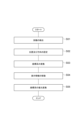
- the trigger detection unit 12 detects the trigger for moving the display information in the virtual space (S01).
- the setting unit 13 sets the position and direction in the virtual space used for moving the display information in the virtual space (S02).
- the transformation unit 14 transforms the coordinate system of the virtual space based on the position and direction in the virtual space set by the setting unit 13 (S03).
- the display information 100 included in the area corresponding to the position and direction in the virtual space set by the setting unit 13 is moved by the moving unit 15 in the converted coordinate system (S04).
- the moving unit 15 restores and transforms the coordinate system of the virtual space to the original coordinate system (S05).
- the movement of the display information 100 by the above processing is reflected in the display by the display section 11 on the display 10 .
- the above is the processing executed by the display 10 according to the present embodiment.
- the display information 100 included in the area 200 is moved according to the position and direction in the virtual space used for moving the display information 100 . Therefore, it is possible to easily move the display information 100, which could not be easily moved by the conventional method, for example, by specifying the display information by the line of sight and the user's operation. Also, the coordinate system of the virtual space is transformed when the display information 100 is moved. Therefore, it is possible to move the display information 100 after converting the display information into a coordinate system that is easy to move. For example, the display information 100 can be easily moved by multiplying the coordinate values by t as described above. As described above, according to the present embodiment, it is possible to easily and appropriately move the display information in the display using the virtual space. As a result, for example, by making the display information 100 appear near the user as described above, it is possible to improve visibility and ease of selection.
- the setting unit 13 may set the position and direction of the line of sight in the virtual space to the position and direction in the virtual space used for moving the display information 100 in the virtual space. . According to this configuration, it is possible to appropriately move the display information 100 according to the position and direction of the line of sight in the virtual space.
- the position and direction in the virtual space used to move the display information 100 in the virtual space may be any position and direction other than the position and direction of the line of sight in the virtual space.
- the moving unit 15 may move the display information 100 included in the fan-shaped or strip-shaped area 200 according to the position and direction in the virtual space set by the setting unit 13. good. According to this configuration, the display information 100 to be moved can be made appropriate.
- the region 200 is not limited to the above shape and may have any shape.
- the moving unit 15 may move each piece of display information 100 to be moved at a speed corresponding to the position of the display information 100 in the area 200 .
- the display information 100 can be moved according to the user's visual sense.
- the moving unit 15 may reduce or enlarge the display information 100 according to the movement of the display information 100 .
- this configuration for example, it is possible to prevent the display information 100 from becoming difficult to see due to the movement of the display information 100 .
- the display information 100 may not be reduced or enlarged.
- the display control device has been described as the display 10 having a display function, but it does not necessarily have to have a display function.
- the display control device is a device (system) that is connected to a display that displays display information arranged in the virtual space according to the line of sight of the virtual space (that is, includes the display unit 11) and that controls display on the display. , the trigger detection unit 12, the setting unit 13, the conversion unit 14, and the movement unit 15 described above.
- some or all of the functional units 12 to 15 described above may be provided in a device such as a server capable of transmitting and receiving information to and from the display.
- each functional unit 12 to 15 provided in a device such as a server may transmit and receive input/output information to/from the display.
- each functional block may be implemented using one device that is physically or logically coupled, or directly or indirectly using two or more devices that are physically or logically separated (e.g. , wired, wireless, etc.) and may be implemented using these multiple devices.
- a functional block may be implemented by combining software in the one device or the plurality of devices.
- Functions include judging, determining, determining, calculating, calculating, processing, deriving, investigating, searching, checking, receiving, transmitting, outputting, accessing, resolving, selecting, choosing, establishing, comparing, assuming, expecting, assuming, Broadcasting, notifying, communicating, forwarding, configuring, reconfiguring, allocating, mapping, assigning, etc. can't
- a functional block (component) responsible for transmission is called a transmitting unit or transmitter.
- the implementation method is not particularly limited.
- the display 10 in one embodiment of the present disclosure may function as a computer that performs information processing of the present disclosure.
- FIG. 6 is a diagram illustrating an example of a hardware configuration of display 10 according to an embodiment of the present disclosure.
- the display 10 described above may be physically configured as a computer device including a processor 1001, a memory 1002, a storage 1003, a communication device 1004, an input device 1005, an output device 1006, a bus 1007, and the like.
- the term "apparatus” can be read as a circuit, device, unit, or the like.
- the hardware configuration of the display 10 may be configured to include one or more of each device shown in the drawing, or may be configured without some of the devices.
- Each function of the display 10 is performed by loading predetermined software (programs) on hardware such as the processor 1001 and the memory 1002 so that the processor 1001 performs calculations, controls communication by the communication device 1004, controls the communication by the memory 1002 and It is realized by controlling at least one of data reading and writing in the storage 1003 .
- the processor 1001 for example, operates an operating system and controls the entire computer.
- the processor 1001 may be configured by a central processing unit (CPU) including an interface with peripheral devices, a control device, an arithmetic device, registers, and the like.
- CPU central processing unit
- each function of display 10 described above may be implemented by processor 1001 .
- the processor 1001 reads programs (program codes), software modules, data, etc. from at least one of the storage 1003 and the communication device 1004 to the memory 1002, and executes various processes according to them.
- programs program codes
- software modules software modules
- data etc.
- the program a program that causes a computer to execute at least part of the operations described in the above embodiments is used.
- each function of display 10 may be implemented by a control program stored in memory 1002 and running on processor 1001 .
- FIG. Processor 1001 may be implemented by one or more chips.
- the program may be transmitted from a network via an electric communication line.
- the memory 1002 is a computer-readable recording medium, and is composed of at least one of, for example, ROM (Read Only Memory), EPROM (Erasable Programmable ROM), EEPROM (Electrically Erasable Programmable ROM), RAM (Random Access Memory), etc. may be
- ROM Read Only Memory
- EPROM Erasable Programmable ROM
- EEPROM Electrical Erasable Programmable ROM
- RAM Random Access Memory
- the memory 1002 may also be called a register, cache, main memory (main storage device), or the like.
- the memory 1002 can store executable programs (program code), software modules, etc. for performing information processing according to an embodiment of the present disclosure.
- the storage 1003 is a computer-readable recording medium, for example, an optical disc such as a CD-ROM (Compact Disc ROM), a hard disk drive, a flexible disc, a magneto-optical disc (for example, a compact disc, a digital versatile disc, a Blu-ray disk), smart card, flash memory (eg, card, stick, key drive), floppy disk, magnetic strip, and/or the like.
- Storage 1003 may also be called an auxiliary storage device.
- the storage medium included in display 10 may be, for example, a database, server, or other suitable medium including at least one of memory 1002 and storage 1003 .
- the communication device 1004 is hardware (transmitting/receiving device) for communicating between computers via at least one of a wired network and a wireless network, and is also called a network device, a network controller, a network card, a communication module, or the like.
- the input device 1005 is an input device (for example, keyboard, mouse, microphone, switch, button, sensor, etc.) that receives input from the outside.
- the output device 1006 is an output device (eg, display, speaker, LED lamp, etc.) that outputs to the outside. Note that the input device 1005 and the output device 1006 may be integrated (for example, a touch panel).
- Each device such as the processor 1001 and the memory 1002 is connected by a bus 1007 for communicating information.
- the bus 1007 may be configured using a single bus, or may be configured using different buses between devices.
- the display 10 includes hardware such as a microprocessor, a digital signal processor (DSP), an ASIC (Application Specific Integrated Circuit), a PLD (Programmable Logic Device), and an FPGA (Field Programmable Gate Array).
- DSP digital signal processor
- ASIC Application Specific Integrated Circuit
- PLD Physical Location Deposition
- FPGA Field Programmable Gate Array
- a part or all of each functional block may be implemented by the hardware.
- processor 1001 may be implemented using at least one of these pieces of hardware.
- Input/output information may be stored in a specific location (for example, memory) or managed using a management table. Input/output information and the like can be overwritten, updated, or appended. The output information and the like may be deleted. The entered information and the like may be transmitted to another device.
- the determination may be made by a value represented by one bit (0 or 1), by a true/false value (Boolean: true or false), or by numerical comparison (for example, a predetermined value).
- notification of predetermined information is not limited to being performed explicitly, but may be performed implicitly (for example, not notifying the predetermined information). good too.
- Software whether referred to as software, firmware, middleware, microcode, hardware description language or otherwise, includes instructions, instruction sets, code, code segments, program code, programs, subprograms, and software modules. , applications, software applications, software packages, routines, subroutines, objects, executables, threads of execution, procedures, functions, and the like.
- software, instructions, information, etc. may be transmitted and received via a transmission medium.
- the software uses at least one of wired technology (coaxial cable, fiber optic cable, twisted pair, digital subscriber line (DSL), etc.) and wireless technology (infrared, microwave, etc.) to website, Wired and/or wireless technologies are included within the definition of transmission medium when sent from a server or other remote source.
- wired technology coaxial cable, fiber optic cable, twisted pair, digital subscriber line (DSL), etc.
- wireless technology infrared, microwave, etc.
- system and “network” used in this disclosure are used interchangeably.
- information, parameters, etc. described in the present disclosure may be expressed using absolute values, may be expressed using relative values from a predetermined value, or may be expressed using other corresponding information. may be represented.
- determining and “determining” used in this disclosure may encompass a wide variety of actions.
- “Judgement” and “determination” are, for example, judging, calculating, computing, processing, deriving, investigating, looking up, searching, inquiring (eg, lookup in a table, database, or other data structure), ascertaining as “judged” or “determined”, and the like.
- "judgment” and “determination” are used for receiving (e.g., receiving information), transmitting (e.g., transmitting information), input, output, access (accessing) (for example, accessing data in memory) may include deeming that a "judgment” or “decision” has been made.
- judgment and “decision” are considered to be “judgment” and “decision” by resolving, selecting, choosing, establishing, comparing, etc. can contain.
- judgment and “decision” may include considering that some action is “judgment” and “decision”.
- judgment (decision) may be read as “assuming”, “expecting”, “considering”, or the like.
- connection means any direct or indirect connection or coupling between two or more elements, It can include the presence of one or more intermediate elements between two elements being “connected” or “coupled.” Couplings or connections between elements may be physical, logical, or a combination thereof. For example, “connection” may be read as "access”.
- two elements are defined using at least one of one or more wires, cables, and printed electrical connections and, as some non-limiting and non-exhaustive examples, in the radio frequency domain. , electromagnetic energy having wavelengths in the microwave and optical (both visible and invisible) regions, and the like.
- any reference to elements using the "first,” “second,” etc. designations used in this disclosure does not generally limit the quantity or order of those elements. These designations may be used in this disclosure as a convenient method of distinguishing between two or more elements. Thus, reference to a first and second element does not imply that only two elements can be employed or that the first element must precede the second element in any way.
- a and B are different may mean “A and B are different from each other.”
- the term may also mean that "A and B are different from C”.
- Terms such as “separate,” “coupled,” etc. may also be interpreted in the same manner as “different.”
Abstract
The present invention easily and appropriately moves display information in a display using a virtual space. A display 10, which is a display control apparatus, is an apparatus for controlling display in the display 10 for displaying display information, which is disposed in a virtual space, in accordance with a line of sight in the virtual space. The display 10 comprises: an opportunity detection unit 12 for detecting an opportunity for moving the display information in the virtual space; a setting unit 13 for setting the position and direction in the virtual space used for moving the display information in the virtual space; a conversion unit 14 for converting a coordinate system of the virtual space on the basis of the set position and direction in the virtual space when the opportunity has been detected; and a movement unit 15 for moving, in the converted coordinate system, the display information included in a region corresponding to the set position and direction in the virtual space and for restoring and converting the coordinate system of the virtual space to the original coordinate system.
Description
本発明は、ディスプレイにおける表示を制御する表示制御装置に関する。
The present invention relates to a display control device that controls display on a display.
従来、ヘッドマウントディスプレイ等のディスプレイにおいて、仮想空間に配置された表示情報を仮想空間の視線に応じて表示することが行われている。仮想空間において表示情報が移動すると、当該移動に応じて表示が変化する。特許文献1には、仮想空間の視線によって仮想空間の表示情報を指定して移動することが示されている。
Conventionally, in displays such as head-mounted displays, display information arranged in a virtual space is displayed according to the line of sight in the virtual space. When the display information moves in the virtual space, the display changes according to the movement. Japanese Patent Laid-Open No. 2002-200001 discloses that display information in a virtual space is designated and moved by a line of sight in the virtual space.
しかしながら、特許文献1に示されるような、視線によって個々に移動させる表示情報を指定する方法では、表示情報の容易かつ適切な移動が困難な場合がある。例えば、上記の方法では、他の表示情報に隠れていて表示されていない表示情報を指定して移動させることができなかったり、困難であったりする。また、視線による指定ではなく、ユーザの操作によって個々に移動させる表示情報を指定する方法でも同様の問題が生じる。
However, with the method of designating display information to be individually moved according to the line of sight, as shown in Patent Document 1, it may be difficult to easily and appropriately move the display information. For example, in the above method, it is difficult or impossible to specify and move display information that is hidden behind other display information and is not displayed. A similar problem also arises in a method of designating display information to be individually moved by a user's operation, instead of designation by line of sight.
本発明の一実施形態は、上記に鑑みてなされたものであり、仮想空間を用いた表示において表示情報を容易かつ適切に移動させることができる表示制御装置を提供することを目的とする。
An embodiment of the present invention has been made in view of the above, and an object thereof is to provide a display control device capable of easily and appropriately moving display information in a display using a virtual space.
本発明の一実施形態に係る表示制御装置は、仮想空間に配置された表示情報を仮想空間の視線に応じて表示するディスプレイにおける表示を制御する表示制御装置であって、仮想空間で表示情報を移動させる契機を検出する契機検出部と、仮想空間での表示情報の移動に用いられる仮想空間での位置及び方向を設定する設定部と、契機検出部によって契機が検出された場合、設定部によって設定された仮想空間での位置及び方向に基づいて、仮想空間の座標系を変換する変換部と、変換部によって変換された座標系において、設定部によって設定された仮想空間での位置及び方向に応じた領域に含まれる表示情報を移動させて、仮想空間の座標系を元の座標系に復元変換する移動部と、を備える。
A display control device according to an embodiment of the present invention is a display control device that controls display on a display that displays display information arranged in a virtual space according to the line of sight in the virtual space, and that displays the display information in the virtual space. a trigger detection unit that detects a trigger for movement; a setting unit that sets the position and direction in the virtual space used to move the display information in the virtual space; a transformation unit that transforms the coordinate system of the virtual space based on the set position and direction in the virtual space; a moving unit that moves the display information included in the corresponding area to restore and transform the coordinate system of the virtual space to the original coordinate system.
本発明の一実施形態に係る表示制御装置では、表示情報の移動に用いられる仮想空間での位置及び方向に応じた領域に含まれる表示情報が移動される。従って、従来の方法では、容易に移動させることができなかった表示情報を容易に移動させることができる。また、表示情報を移動させる際に仮想空間の座標系が変換される。このため、表示情報を移動しやすい座標系に変換した上で表示情報を移動させることができる。このように本発明の一実施形態に係る表示制御装置によれば、仮想空間を用いた表示において表示情報を容易かつ適切に移動させることができる。
In the display control device according to one embodiment of the present invention, the display information included in the area corresponding to the position and direction in the virtual space used for moving the display information is moved. Therefore, it is possible to easily move display information that could not be easily moved by the conventional method. Also, the coordinate system of the virtual space is transformed when the display information is moved. Therefore, the display information can be moved after being converted into a coordinate system that facilitates movement of the display information. As described above, according to the display control device according to the embodiment of the present invention, it is possible to easily and appropriately move the display information in the display using the virtual space.
本発明の一実施形態によれば、仮想空間を用いた表示において表示情報を容易かつ適切に移動させることができる。
According to one embodiment of the present invention, it is possible to easily and appropriately move display information in a display using virtual space.
以下、図面と共に本発明に係る表示制御装置の実施形態について詳細に説明する。なお、図面の説明においては同一要素には同一符号を付し、重複する説明を省略する。
Hereinafter, an embodiment of the display control device according to the present invention will be described in detail along with the drawings. In the description of the drawings, the same elements are denoted by the same reference numerals, and overlapping descriptions are omitted.
図1に本実施形態に係る表示制御装置であるディスプレイ10の機能構成を示す。表示装置であるディスプレイ10は、ディスプレイ10自身における表示を制御する。ディスプレイ10は、仮想空間(例えば、仮想的な三次元空間)に配置された表示情報を仮想空間の視線に応じて表示する。表示情報は、例えば、文字、画像及び動画像等のコンテンツである。また、表示情報は、上記以外のものであっても、仮想空間に配置されて仮想空間の視線に応じて表示できるものであれば、どのようなものであってもよい。
FIG. 1 shows the functional configuration of a display 10, which is a display control device according to this embodiment. The display 10, which is a display device, controls display on the display 10 itself. The display 10 displays display information arranged in a virtual space (for example, a virtual three-dimensional space) according to the line of sight in the virtual space. The display information is, for example, contents such as characters, images, and moving images. The display information may be anything other than the above as long as it can be arranged in the virtual space and displayed according to the line of sight in the virtual space.
例えば、ディスプレイ10は、AR(Augmented Reality)、MR(Mixed Reality)又はVR(Virtual Reality)等のXRによって仮想のコンテンツ(表示情報)の表示を行うディスプレイである。ディスプレイ10は、ユーザの眼の部分に装着される透過型のディスプレイであってもよい。例えば、ディスプレイ10は、眼鏡型のヘッドマウントディスプレイ、即ち、シースルーグラス(スマートグラス、XRグラス)であってもよい。以下では、ディスプレイ10は、ユーザの眼の部分、即ち、ユーザの頭部に装着されるものとして説明する。但し、ディスプレイ10は、ユーザに装着されるものである必要はない。
For example, the display 10 is a display that displays virtual content (display information) by XR such as AR (Augmented Reality), MR (Mixed Reality) or VR (Virtual Reality). The display 10 may be a transmissive display worn over the user's eye. For example, the display 10 may be a glasses-type head-mounted display, that is, see-through glasses (smart glasses, XR glasses). In the following description, the display 10 is assumed to be worn on the user's eye, ie, on the user's head. However, the display 10 need not be worn by the user.
ディスプレイ10は、仮想空間における視線の基準位置(視線の始点)から仮想空間の視線の方向に見える領域の表示情報を見えた状態で表示する。仮想空間の視線は、仮想空間の視線の基準位置と、仮想空間の視線の方向とを含んで構成される。ディスプレイ10では、仮想空間の視線を移動させて表示を行うことができる。仮想空間の視線を移動することで仮想空間において見える表示情報が変化し、ディスプレイ10における表示も変化する。
The display 10 displays the display information of the area visible in the direction of the line of sight in the virtual space from the reference position of the line of sight (the starting point of the line of sight) in the virtual space. The line of sight in the virtual space includes the reference position of the line of sight in the virtual space and the direction of the line of sight in the virtual space. The display 10 can display by moving the line of sight in the virtual space. By moving the line of sight in the virtual space, the display information seen in the virtual space changes, and the display on the display 10 also changes.
仮想空間のディスプレイ10の視線は、ディスプレイ10の現実空間での位置又は姿勢に基づくものであってもよい。そのため、ディスプレイ10には、ディスプレイ10自身の動き(即ち、位置の変動)及び向き(即ち、姿勢)を検出するセンサが設けられていてもよい。例えば、加速度を検出する加速度センサ及び角速度を検出するジャイロセンサが設けられていてもよい。ディスプレイ10は、これらのセンサによって、ディスプレイ10自身の動き及び向きを検出して、検出した動き及び向きに応じて仮想空間の視線を移動させてもよい。即ち、ディスプレイ10が装着されるユーザの頭部(顔)の向きに応じて視線が移動されてもよい。但し、仮想空間の視線の移動は、上記以外のセンサによる、位置又は姿勢の検出に応じて行われてもよい。
The line of sight of the display 10 in the virtual space may be based on the position or orientation of the display 10 in the real space. Therefore, the display 10 may be provided with a sensor that detects the movement (ie, positional variation) and orientation (ie, attitude) of the display 10 itself. For example, an acceleration sensor that detects acceleration and a gyro sensor that detects angular velocity may be provided. The display 10 may detect the movement and orientation of the display 10 itself using these sensors, and move the line of sight in the virtual space according to the detected movement and orientation. That is, the line of sight may be moved according to the direction of the head (face) of the user wearing the display 10 . However, the movement of the line of sight in the virtual space may be performed according to the detection of the position or orientation by sensors other than those described above.
また、仮想空間の視線の移動は、上記のようにセンサによるものではなく、ディスプレイ10に対するユーザの操作によって行われてもよい。仮想空間の視線の移動を含む、仮想空間の視線を用いたディスプレイ10における表示は、従来のAR、MR又はVR等による表示と同様に行われればよい。なお、仮想空間に関する情報の保持及び処理は、ディスプレイ10において行われてもよいし、ディスプレイ10に接続されるクラウド等において行われてもよい。
Also, the movement of the line of sight in the virtual space may be performed by the user's operation on the display 10 instead of by the sensor as described above. The display on the display 10 using the line of sight in the virtual space, including the movement of the line of sight in the virtual space, may be performed in the same manner as the conventional display by AR, MR, VR, or the like. The holding and processing of information regarding the virtual space may be performed in the display 10 or may be performed in a cloud or the like connected to the display 10 .
仮想空間の視線の移動は、予め設定された方法で行われる。例えば、仮想空間の視線の移動は、所定の自由度で行われる。予め設定した自由度は、例えば、6DoF(Degree of Freedom)である。
The movement of the line of sight in the virtual space is performed according to a preset method. For example, movement of the line of sight in the virtual space is performed with a predetermined degree of freedom. The preset degree of freedom is, for example, 6 DoF (Degree of Freedom).
6DoFでは、仮想空間の視線の基準位置が仮想空間のX軸、Y軸、Z軸の3軸方向に移動することができる。また、6DoFでは、仮想空間の視線の方向が仮想空間のX軸、Y軸、Z軸の3軸周りに回転することができる。従って、ディスプレイ10を装着しているユーザが頭部を動かすと、その動きに応じた表示情報を見ることが可能である。但し、上記以外の自由度及び上記以外の方法で仮想空間の視線の移動が行われてもよい。
In 6DoF, the reference position of the line of sight in the virtual space can be moved in the three axial directions of the virtual space's X, Y, and Z axes. In 6DoF, the direction of the line of sight in the virtual space can be rotated around three axes of the X, Y, and Z axes of the virtual space. Therefore, when the user wearing the display 10 moves his/her head, it is possible to see display information according to the movement. However, the line of sight in the virtual space may be moved by a degree of freedom other than the above and by a method other than the above.
ディスプレイ10では、表示に係る操作、例えば、表示情報に対するユーザの操作が行われてもよい。ディスプレイ10は、ユーザの操作を受け付けて、操作を表示に反映させる。例えば、仮想空間での表示情報の生成、移動、拡大及び縮小、並びに表示情報に対する文字入力等の操作が行われてもよい。操作は、例えば、ディスプレイ10を装着したユーザによって携帯される、スマートフォン等の情報処理装置が用いられて行われてもよい。その場合、予めディスプレイ10とスマートフォンとが情報の送受信が可能であるように接続されている。
On the display 10, an operation related to display, for example, a user's operation on display information may be performed. The display 10 receives a user's operation and reflects the operation on the display. For example, operations such as generation, movement, enlargement and reduction of display information in the virtual space, and character input for display information may be performed. The operation may be performed using, for example, an information processing device such as a smart phone carried by the user wearing the display 10 . In that case, the display 10 and the smartphone are connected in advance so that information can be transmitted and received.
また、操作は、ヘッドマウントディスプレイに付属する専用コントローラによって行われてもよい。また、操作は、ユーザのジェスチャによって行われてもよい。ジェスチャを行うユーザの部分は、例えば、手である。即ち、ハンドトラッキングジェスチャによる操作が行われてもよい。但し、手以外の部分でのジェスチャによる操作が行われてもよい。ユーザのジェスチャによる操作が行われる場合は、ジェスチャを行う部分を撮像できるようにカメラを設けておき、カメラによって撮像された動画像によってジェスチャが判断される。また、操作は、上記以外の任意の方法で行われてもよい。ディスプレイ10における上記の表示及び操作は、従来の方法と同様に行われればよい。
Also, the operation may be performed by a dedicated controller attached to the head-mounted display. Also, the operation may be performed by a user's gesture. The part of the user that makes the gesture is, for example, the hand. That is, an operation using a hand tracking gesture may be performed. However, an operation may be performed by a gesture using a part other than the hand. When an operation is performed by a user's gesture, a camera is provided so as to capture an image of the part where the gesture is performed, and the gesture is determined based on the moving image captured by the camera. Also, the operation may be performed in any manner other than the above. The above display and operation on the display 10 may be performed in the same manner as in the conventional method.
ディスプレイ10における表示と、他のディスプレイにおける表示とには、共通の仮想空間に共通して配置された表示情報が用いられてもよい。即ち、複数のディスプレイの間で仮想空間及び表示情報が共有されてもよい。仮想空間及び表示情報が共有される複数のディスプレイは、予め設定される。ディスプレイ10における表示と、他のディスプレイにおける表示とにおける仮想空間の視線は、ディスプレイ毎の独立したものが用いられてもよい。ディスプレイにおける視線が異なっていれば、例えば、それぞれのディスプレイではそれぞれの視線に応じた異なる表示が行われる。
Display information commonly arranged in a common virtual space may be used for the display on the display 10 and the display on another display. That is, the virtual space and display information may be shared among multiple displays. The multiple displays with which the virtual space and display information are shared are preset. The line of sight of the virtual space in the display on the display 10 and in the display on the other display may be independent for each display. If the lines of sight on the displays are different, for example, different displays according to the respective lines of sight are performed on each display.
仮想空間は、現実空間に対応付いたものであってもよい。これによって、例えば、ディスプレイ10を現実空間の特定の位置に向けることで、当該特定の位置に対応する仮想空間の位置に配置された表示情報を表示させることができる。上記のように複数のディスプレイ間で仮想空間及び表示情報が共有されて、仮想空間が現実空間に対応付いたものにすることで、複数のディスプレイのユーザ間での非同期コミュニケーションを行うことができる。例えば、あるユーザが仮想空間に自身が生成した表示情報を配置した後、別のユーザが表示情報の配置位置に対応する現実空間の位置にディスプレイを向けることで、当該表示情報を当該別のユーザのディスプレイに表示させることができる。
The virtual space may correspond to the real space. Accordingly, for example, by directing the display 10 to a specific position in the physical space, it is possible to display the display information arranged at the position in the virtual space corresponding to the specific position. As described above, the virtual space and display information are shared among the multiple displays, and the virtual space is associated with the real space, enabling asynchronous communication among the users of the multiple displays. For example, after a user arranges display information generated by himself/herself in a virtual space, another user directs the display to a position in the real space corresponding to the arrangement position of the display information so that the display information can be transferred to the other user. can be displayed on the display.
上記の表示情報は、例えば、他のユーザへのメッセージ(言葉、テキスト)又は三次元動画である。また、表示情報を、仮想空間において浮遊するシャボン玉の表示とし、ユーザの操作等によってシャボン玉が割られると上記のメッセージ及び三次元動画等のコンテンツを参照できるようにしてもよい。即ち、シャボン玉の中にコンテンツを入れた状態で空間上に表示してもよい。
The above display information is, for example, a message (words, text) to another user or a three-dimensional video. Further, the display information may be a display of a soap bubble floating in the virtual space, and when the soap bubble is broken by a user's operation or the like, the message and content such as the three-dimensional video may be referred to. In other words, the content may be displayed in space in a state where the content is placed in a soap bubble.
ディスプレイ10としては、従来の上記の機能を有するディスプレイを用いることができる。また、ディスプレイ10は、通信機能を有していてもよい。ディスプレイ10の通信機能は、上記の仮想空間及び表示情報の共有、並びに本実施形態に係る機能の実現に用いられてもよい。また、ディスプレイ10の上述した機能及び後述する本実施形態に係る機能の一部は、表示装置(例えば、上述したシースルーグラス)に接続される情報処理装置(例えば、スマートフォン又はPC(パーソナルコンピュータ))が有していてもよい。即ち、表示装置と情報処理装置とを含んで本実施形態に係るディスプレイ10が実現されてもよい。
As the display 10, a conventional display having the above functions can be used. Moreover, the display 10 may have a communication function. The communication function of the display 10 may be used to share the virtual space and display information described above and to realize the functions according to the present embodiment. In addition, some of the above-described functions of the display 10 and functions according to the present embodiment described later are an information processing device (such as a smartphone or a PC (personal computer)) connected to a display device (such as the above-described see-through glasses). may have. That is, the display 10 according to the present embodiment may be realized by including the display device and the information processing device.
引き続いて、本実施形態に係るディスプレイ10の機能を説明する。図1に示すようにディスプレイ10は、表示部11と、契機検出部12と、設定部13と、変換部14と、移動部15とを備えて構成される。また、ディスプレイ10は、上記以外にも従来のシースルーグラス等の従来の表示装置が備える機能を備えていてもよい。
Next, the functions of the display 10 according to this embodiment will be explained. As shown in FIG. 1 , the display 10 includes a display section 11 , a trigger detection section 12 , a setting section 13 , a conversion section 14 and a movement section 15 . In addition, the display 10 may have functions other than those described above that conventional display devices, such as conventional see-through glasses, have.
ディスプレイ10の以下に説明する機能は、仮想空間に配置された表示情報を移動するためのものである。例えば、表示情報が仮想空間の視線の基準位置から離れていると、当該表示情報は小さく表示される。当該表示情報を視線の基準位置に近づけるように移動させると、当該表示情報は大きく表示されて、ユーザがよく見えるようになる。
The functions of the display 10 described below are for moving the display information arranged in the virtual space. For example, when the display information is away from the reference position of the line of sight in the virtual space, the display information is displayed in a small size. When the display information is moved so as to approach the reference position of the line of sight, the display information is displayed in a large size so that the user can see it clearly.
上述したように、視線によって個々に移動させる表示情報を指定(選択)する従来の方法では、他の表示情報に隠れていて表示されていない表示情報を指定して移動させることができなかったり、困難であったりする。また、表示されている複数の表示情報、即ち、ユーザの視界の範囲に含まれる複数の表示情報をまとめて仮想空間の視線の基準位置に近づける場合には、上記の従来の方法では容易かつ適切な移動が困難である。視線による指定ではなく、ユーザの操作によって個々に移動させる表示情報を指定する方法でも同様の問題が生じる。
As described above, in the conventional method of specifying (selecting) display information to be individually moved according to the line of sight, it is not possible to specify and move display information that is hidden behind other display information and is not displayed. It can be difficult. In addition, when a plurality of pieces of display information being displayed, that is, a plurality of pieces of display information included in the range of the user's field of vision are collectively brought closer to the reference position of the line of sight in the virtual space, the above-described conventional method is easy and appropriate. movement is difficult. A similar problem arises in a method of specifying display information to be individually moved by a user's operation instead of specifying by line of sight.
また、ハンドトラッキングジェスチャ又は専用コントローラ等によって、ユーザが手で表示情報を触れるような操作によって移動する表示情報を指定する方法も考えられる。しかしながら、この方法では、指定できる表示情報が手の届く範囲に限定される。遠くの表示情報を移動させようとすると、例えば、ユーザ自身の移動が必要となる。また、ポインタビームによって移動する表示情報を指定する方法も考えられる。しかしながら、この方法では、特に遠くの表示情報を指定する場合には繊細な操作が要求される。また、上記の各方法では、複数の表示情報をまとめて移動させることができなかったり、困難であったりする。本実施形態に係る機能は、上記の問題を解決し、表示情報を容易かつ適切に移動させるようにするものである。例えば、本実施形態に係る機能は、ユーザがディスプレイ10を装着した状態で、手の届かない距離にある表示情報をユーザの負担なく操作できるようにするものである。
It is also conceivable to use a hand tracking gesture, a dedicated controller, or the like to designate display information that moves when the user touches the display information with his or her hand. However, this method limits the display information that can be specified within reach. For example, the user himself/herself needs to move when trying to move the displayed information in the distance. A method of designating display information to be moved by a pointer beam is also conceivable. However, this method requires a delicate operation, especially when specifying distant display information. Moreover, in each of the above methods, it may be difficult or impossible to collectively move a plurality of pieces of display information. The function according to the present embodiment solves the above problem and allows the displayed information to be moved easily and appropriately. For example, the function according to the present embodiment enables the user to operate display information that is out of reach with the user wearing the display 10 without any burden on the user.
なお、ディスプレイ10での表示に係る表示情報の移動は、本実施形態に係る機能によるものに加えて、本実施形態に係る機能以外によっても行われてもよい。例えば、上記の方法の何れかで表示情報が移動されてもよい。
It should be noted that the movement of display information related to display on the display 10 may be performed by functions other than the functions according to the present embodiment, in addition to the functions according to the present embodiment. For example, display information may be moved in any of the ways described above.
表示部11は、ディスプレイ10での表示を行う機能部である。表示部11は、ディスプレイ10に表示する表示情報を入力して表示する。例えば、表示部11は、ディスプレイ10に記憶される表示情報を入力してもよいし、外部から表示情報を受信して入力してもよい。上述したように表示部11は、仮想空間に配置された表示情報を仮想空間の視線に応じて表示する。また、上述したように表示部11は、他のディスプレイとの間で仮想空間及び表示情報を共有してもよい。仮想空間及び表示情報の共有は、例えば、他のディスプレイとの間で表示情報及び当該表示情報が配置される仮想空間の位置を示す情報を送受信することで行われる。また、仮想空間及び表示情報の共有は、ディスプレイ間の直接のやり取りではなく、ディスプレイそれぞれが通信可能なサーバを介して行われてもよい。また、上記以外の方法でディスプレイ間の仮想空間及び表示情報の共有が行われてもよい。
The display unit 11 is a functional unit that displays on the display 10. The display unit 11 receives and displays display information to be displayed on the display 10 . For example, the display unit 11 may input display information stored in the display 10, or receive and input display information from the outside. As described above, the display unit 11 displays the display information arranged in the virtual space according to the line of sight in the virtual space. Moreover, as described above, the display unit 11 may share the virtual space and display information with other displays. The sharing of the virtual space and the display information is performed, for example, by transmitting/receiving the information indicating the position of the display information and the virtual space where the display information is arranged to/from another display. Also, sharing of virtual space and display information may be performed via a server with which each display can communicate, instead of direct exchange between displays. Also, the virtual space and the display information may be shared between the displays by a method other than the above.
表示部11による上記の機能は、従来の機能と同様のものでよい。また、後述するように表示部11による表示は、移動部15からの制御を受ける。
The above function of the display unit 11 may be the same as the conventional function. Further, the display by the display unit 11 is controlled by the moving unit 15 as will be described later.
契機検出部12は、仮想空間で表示情報を移動させる契機(トリガ)を検出する機能部である。例えば、契機検出部12は、上記の契機となるユーザの操作を予め記憶しておく。契機検出部12は、ユーザの操作を受け付けて、受け付けたユーザの操作が予め記憶したものであれば、上記の契機を検出したとする。上記の契機となるユーザの操作は、例えば、ボタン押下、ジェスチャ又は音声による特定のコマンドの入力である。なお、契機は、上記以外のユーザの操作であってもよいし、ユーザ操作以外であってもよい。契機検出部12は、契機を検出すると設定部13にその旨を通知する。
The opportunity detection unit 12 is a functional unit that detects an opportunity (trigger) for moving display information in the virtual space. For example, the trigger detection unit 12 stores in advance the user's operation that serves as the trigger. It is assumed that the trigger detection unit 12 has detected the above-described trigger when the user's operation is received and the received user's operation is stored in advance. The user's operation that triggers the above is, for example, pressing a button, gesturing, or inputting a specific command by voice. Note that the trigger may be a user's operation other than the above, or may be other than the user's operation. When the trigger detection unit 12 detects the trigger, the trigger detection unit 12 notifies the setting unit 13 to that effect.
設定部13は、仮想空間での表示情報の移動に用いられる仮想空間での位置及び方向を設定する機能部である。設定部13は、仮想空間の視線の位置及び方向を、仮想空間での表示情報の移動に用いられる仮想空間での位置及び方向に設定してもよい。
The setting unit 13 is a functional unit that sets the position and direction in the virtual space used to move the display information in the virtual space. The setting unit 13 may set the position and direction of the line of sight in the virtual space to the position and direction in the virtual space used for moving the display information in the virtual space.
設定される位置及び方向は、移動する表示情報を決定するための基準となるものである。例えば、予め仮想空間の視線の基準位置及び方向を、移動に用いられる位置及び方向として用いることとしておく。設定部13は、契機検出部12から契機の検出の通知を受ける。設定部13は、当該通知を受けたタイミングで、表示部11が保持している仮想空間の視線の基準位置及び方向を示す情報を取得し、当該視線の基準位置及び方向を、表示情報の移動に用いられる仮想空間での位置及び方向として設定する。仮想空間の視線の基準位置を示す情報は、例えば、仮想空間の座標系(絶対座標系)での座標である。仮想空間の視線の方向を示す情報は、例えば、仮想空間の座標系でのベクトルである。仮想空間の座標系は、例えば、直交座標系(X,Y,Z)である。
The position and direction that are set are the criteria for determining the displayed information to move. For example, the reference position and direction of the line of sight in the virtual space are used in advance as the position and direction used for movement. The setting unit 13 receives notification of the detection of the trigger from the trigger detection unit 12 . At the timing of receiving the notification, the setting unit 13 acquires information indicating the reference position and direction of the line of sight in the virtual space held by the display unit 11, and moves the reference position and direction of the line of sight according to the movement of the display information. Set as the position and direction in the virtual space used for The information indicating the reference position of the line of sight in the virtual space is, for example, coordinates in the coordinate system (absolute coordinate system) of the virtual space. The information indicating the direction of the line of sight in the virtual space is, for example, a vector in the coordinate system of the virtual space. The coordinate system of the virtual space is, for example, an orthogonal coordinate system (X, Y, Z).
設定部13は、設定した、移動に用いられる仮想空間での位置及び方向を示す情報を変換部14に出力する。なお、表示情報の移動に用いられる仮想空間での位置及び方向は、仮想空間の視線の位置及び方向とする必要はなく、それ以外の位置及び方向としてもよい。また、表示情報の移動に用いられる仮想空間での位置及び方向は、上記のように予め記憶された設定基準によって設定される必要はなく、例えば、設定する時点でユーザの操作を受け付けて設定されてもよい。
The setting unit 13 outputs information indicating the set position and direction in the virtual space used for movement to the conversion unit 14 . Note that the position and direction in the virtual space used for moving the display information need not be the position and direction of the line of sight in the virtual space, and may be other positions and directions. Further, the position and direction in the virtual space used to move the display information need not be set according to the previously stored setting criteria as described above. may
変換部14は、契機検出部12によって契機が検出された場合、設定部13によって設定された仮想空間での位置及び方向に基づいて、仮想空間の座標系を変換する機能部である。変換部14は、設定部13から、移動に用いられる仮想空間での位置及び方向を示す情報を入力する。例えば、変換部14は、入力した情報によって示される位置を原点とし、当該情報によって示される方向を原点から延びる予め設定した方向とするように仮想空間の座標軸を変換する。上記のように仮想空間の視線の基準位置及び方向を、移動に用いられる位置及び方向とした場合、視線の基準位置が原点となる座標系に変換される。即ち、変換部14は、現実空間に対応する仮想空間の座標系(X,Y,Z)を、ユーザ視点の座標系(X´,Y´,Z´)(仮座標系)に変換する。なお、変換後の座標系は、上記のように直交座標系でもよいし、それ以外の座標系(例えば、球面座標系)でもよい。
The conversion unit 14 is a functional unit that converts the coordinate system of the virtual space based on the position and direction in the virtual space set by the setting unit 13 when the trigger detection unit 12 detects the trigger. The conversion unit 14 receives information from the setting unit 13 indicating the position and direction in the virtual space used for movement. For example, the conversion unit 14 converts the coordinate axes of the virtual space so that the position indicated by the input information is the origin, and the direction indicated by the information is the preset direction extending from the origin. As described above, when the reference position and direction of the line of sight in the virtual space are the position and direction used for movement, the reference position of the line of sight is converted into a coordinate system having the origin. That is, the transformation unit 14 transforms the coordinate system (X, Y, Z) of the virtual space corresponding to the real space into the coordinate system (X', Y', Z') of the user's viewpoint (temporary coordinate system). The coordinate system after conversion may be an orthogonal coordinate system as described above, or may be another coordinate system (for example, a spherical coordinate system).
座標系の変換自体は、従来の方法によって行われればよい。変換部14は、変換後の座標系(X´,Y´,Z´)における表示情報の位置(座標)も算出する。変換部14は、変換後の座標系(X´,Y´,Z´)を示す情報を移動部15に出力する。
The transformation of the coordinate system itself should be performed by the conventional method. The conversion unit 14 also calculates the position (coordinates) of the display information in the coordinate system (X', Y', Z') after conversion. The conversion unit 14 outputs information indicating the coordinate system (X′, Y′, Z′) after conversion to the moving unit 15 .
移動部15は、変換部14によって変換された座標系において、設定部13によって設定された仮想空間での位置及び方向に応じた領域に含まれる表示情報を移動させて、仮想空間の座標系を元の座標系に復元変換する機能部である。移動部15は、設定部13によって設定された仮想空間での位置及び方向に応じた扇形状又は帯状の領域に含まれる表示情報を移動させてもよい。移動部15は、移動させる表示情報毎に、上記の領域における当該表示情報の位置に応じた速度で移動させてもよい。移動部15は、表示情報の移動に応じて、当該表示情報を縮小又は拡大してもよい。移動部15は、例えば、以下のような処理を行う。
The moving unit 15 moves the display information included in the area corresponding to the position and direction in the virtual space set by the setting unit 13 in the coordinate system transformed by the transforming unit 14, thereby moving the coordinate system of the virtual space. This is a functional unit that restores and transforms to the original coordinate system. The moving unit 15 may move the display information included in the fan-shaped or belt-shaped area according to the position and direction in the virtual space set by the setting unit 13 . The moving unit 15 may move each piece of display information to be moved at a speed corresponding to the position of the display information in the above area. The moving unit 15 may reduce or enlarge the display information according to the movement of the display information. The moving unit 15 performs, for example, the following processing.
移動部15は、変換部14から変換後の座標系(X´,Y´,Z´)を示す情報を入力する。移動部15は、変換後の座標系において、表示情報の移動に用いる領域(範囲)を設定する。例えば、図2(a)に示すように、移動部15は、変換後の座標系において扇形状の領域200を設定する。より具体的には、当該領域200は、円錐状又は角錐状に広がる領域である。当該領域200の広がる方向と垂直な方向(例えば、上方)から見ると、当該領域200は図2(a)に示すように扇形状に広がっている。なお、扇形状は、無限に広がっていてもよいし、一定の大きさを有するものであってもよい。
The moving unit 15 receives information indicating the coordinate system (X', Y', Z') after conversion from the converting unit 14. The moving unit 15 sets a region (range) used for moving the display information in the converted coordinate system. For example, as shown in FIG. 2A, the moving unit 15 sets a fan-shaped area 200 in the coordinate system after conversion. More specifically, the region 200 is a conical or pyramidal region. When viewed from a direction perpendicular to the direction in which the region 200 extends (for example, from above), the region 200 extends in a fan shape as shown in FIG. 2(a). The fan shape may extend infinitely or may have a fixed size.
移動部15は、設定部13によって設定された仮想空間での位置及び方向に応じて、上記の領域200を設定する。具体的には、移動部15は、設定部13によって設定された位置に対応する変換後の座標系の原点(即ち、仮想空間の視線の基準位置)を頂点として上記の領域200を設定する。また、移動部15は、設定部13によって設定された方向に対応する変換後の座標系の方向(即ち、仮想空間の視線の方向)を、上記の領域200の原点から広がる角度の中心の方向として上記の領域200を設定する。即ち、移動部15は、変換後の座標系において、ディスプレイ10で表示される範囲に対応する領域200、即ち、ユーザの視界に対応する領域200を設定する。なお、設定される領域200は、ディスプレイ10で表示される範囲に一致していなくてもよい。設定される領域200と、ディスプレイ10で表示される範囲とが一致し、かつディスプレイ10が矩形の表示をするものである場合、設定される領域200はそれにあわせて角錐状に広がる領域となる。
The movement unit 15 sets the area 200 according to the position and direction in the virtual space set by the setting unit 13 . Specifically, the moving unit 15 sets the region 200 with the origin of the coordinate system after conversion corresponding to the position set by the setting unit 13 (that is, the reference position of the line of sight in the virtual space) as the vertex. Further, the moving unit 15 shifts the direction of the coordinate system after conversion corresponding to the direction set by the setting unit 13 (that is, the direction of the line of sight in the virtual space) to the direction of the center of the angle extending from the origin of the region 200. The area 200 is set as above. That is, the moving unit 15 sets an area 200 corresponding to the range displayed on the display 10, that is, an area 200 corresponding to the field of view of the user, in the converted coordinate system. Note that the set area 200 does not have to match the range displayed on the display 10 . If the area 200 to be set matches the area displayed on the display 10 and the display 10 displays a rectangular shape, the area 200 to be set will expand in a pyramidal shape accordingly.
移動部15は、設定された領域200に含まれる表示情報100を判断する。なお、領域200に含まれる表示情報100は、表示情報100全体が領域200に含まれるものとしてもよいし、表示情報100毎に予め設定される中心軸が領域200に含まれるものとしてもよい。移動部15は、設定された領域200に含まれる表示情報100を移動対象の表示情報100とする。図2(b)に示すように、移動部15は、移動対象の表示情報100を予め設定された方向に移動させる。図2(b)に示すように、予め設定された方向は、例えば、領域200の頂点である原点(即ち、仮想空間の視線の基準位置)に向かう方向である。即ち、ディスプレイ10における表示において、表示情報100がユーザに近づくように移動される(ユーザに引き寄せられる)。
The moving unit 15 determines the display information 100 included in the set area 200 . The display information 100 included in the area 200 may include the entire display information 100 , or may include the center axis preset for each display information 100 . The moving unit 15 sets the display information 100 included in the set area 200 as the display information 100 to be moved. As shown in FIG. 2B, the moving unit 15 moves the display information 100 to be moved in a preset direction. As shown in FIG. 2B, the preset direction is, for example, the direction toward the origin, which is the vertex of the area 200 (that is, the reference position of the line of sight in the virtual space). That is, in the display on the display 10, the display information 100 is moved closer to the user (attracted to the user).
表示情報100の移動は原点へ向かうものであるため、表示情報100の変換後の座標系における座標の値をt倍(tは1未満の正の値)することで行われる。移動部15は、表示情報100を移動させると仮想空間の座標系を元の座標系に復元変換する。座標系の復元変換自体は、従来の方法によって行われればよい。表示部11は、移動された表示情報100をディスプレイ10での表示に反映する。従って、ユーザは、移動されて表示される表示情報100を見ることができる。
Since the display information 100 is moved toward the origin, it is performed by multiplying the coordinate value of the coordinate system after the display information 100 is converted by t (t is a positive value less than 1). When the display information 100 is moved, the moving unit 15 restores and transforms the coordinate system of the virtual space to the original coordinate system. The restoration transformation itself of the coordinate system may be performed by a conventional method. The display unit 11 reflects the moved display information 100 on the display on the display 10 . Therefore, the user can see the display information 100 that is moved and displayed.
また、移動部15は、表示情報100の移動を予め設定した一定の速度で行ってもよい。例えば、上記のtの値を複数用意しておいて、移動部15が順番に変換後の座標を算出することで、ディスプレイ10における表示において表示情報100が徐々に移動する(ユーザに近づいてくる)ようにしてもよい。また、移動を中止するユーザの操作を受け付けるようにしておき、当該操作を受け付けるまで移動するようにしてもよい。
Further, the moving unit 15 may move the display information 100 at a preset constant speed. For example, a plurality of values of t are prepared, and the moving unit 15 sequentially calculates the coordinates after conversion, so that the display information 100 gradually moves in the display on the display 10 (when the user gets closer to the user). ). Alternatively, the user's operation to stop the movement may be received, and the movement may continue until the user's operation is received.
なお、表示情報100の移動方向は、原点に向かう方向ではなく、原点から離れる方向、即ち、ユーザから遠ざける方向であってもよい。また、表示情報100の移動方向は、上記以外の方向であってもよい。また、契機検出部12によって検出される契機の種別と表示情報100の移動方向とを予め対応付けておき、検出される契機の種別に応じた方向に表示情報100を移動させてもよい。また、変換後の座標系における表示情報100の移動は上記以外の方法で行われてもよい。
Note that the moving direction of the display information 100 may be a direction away from the origin, that is, a direction away from the user, instead of the direction toward the origin. Also, the moving direction of the display information 100 may be a direction other than the above. Further, the type of the trigger detected by the trigger detector 12 may be associated in advance with the moving direction of the display information 100, and the display information 100 may be moved in the direction corresponding to the detected trigger type. Moreover, the movement of the display information 100 in the coordinate system after conversion may be performed by a method other than the above.
また、移動部15は、移動させる表示情報100毎に、上記の領域200における当該表示情報100の位置に応じた速度で移動させてもよい。例えば、移動部15は、図2(a)に示すように領域200の原点から広がる角度に応じた部分領域を設定する。具体的には、移動部15は、領域200の原点から広がる中央の角度Θの部分領域210と、中央の角度Θを除いた角度Θ´の部分領域220とを設定する。上記の角度Θは、例えば、人間の中心視の角度である1~2°とする。上記の角度Θ´は、例えば、人間の有効視野の範囲の角度である4~20°とする。
Further, the moving unit 15 may move each piece of display information 100 to be moved at a speed corresponding to the position of the display information 100 in the area 200 described above. For example, the moving unit 15 sets a partial area corresponding to an angle extending from the origin of the area 200 as shown in FIG. 2(a). Specifically, the moving unit 15 sets a central partial area 210 extending from the origin of the area 200 and having an angle Θ, and a partial area 220 having an angle Θ′ excluding the central angle Θ. The above angle Θ is, for example, 1 to 2°, which is the central vision angle of a human being. The above angle Θ′ is, for example, 4 to 20°, which is the range of the effective visual field of humans.
移動部15は、部分領域210に含まれる表示情報100を速度vで移動させ、部分領域220に含まれる表示情報100を速度svで移動させる。なお、v及びsは予め設定された値であり、0<s<1である。即ち、内側の部分領域210に含まれる表示情報100を速く移動させ、外側の部分領域210に含まれる表示情報100を遅く移動させる。これによって、ディスプレイ10の表示画面の中心に近い部分では表示情報100が速く移動し、その外側の部分では表示情報100が遅く移動する。このように表示情報100を移動させることで、表示情報100の移動をユーザの視覚的な感覚にあったものとすることができる。
The moving unit 15 moves the display information 100 included in the partial area 210 at a speed v, and moves the display information 100 included in the partial area 220 at a speed sv. Note that v and s are preset values, and 0<s<1. That is, the display information 100 included in the inner partial area 210 is moved quickly, and the display information 100 included in the outer partial area 210 is moved slowly. As a result, the display information 100 moves fast in the portion near the center of the display screen of the display 10, and the display information 100 moves slowly in the outer portion. By moving the display information 100 in this way, the movement of the display information 100 can be adapted to the user's visual sense.
上記の領域200及び表示情報100の移動方向は、上述したものに限られない。例えば、図3に示すように、移動部15は、設定部13によって設定された仮想空間での位置及び方向に応じた帯状の領域200を設定し、表示情報100の移動に用いてもよい。具体的には、移動部15は、設定部13によって設定された位置に対応する変換後の座標系の原点を端部に含み、設定部13によって設定された方向に延びる帯状の領域200を設定する。また、移動部15は、設定された領域200に含まれる表示情報100を、設定部13によって設定された方向と平行に移動させる。また、変換後の座標系の全体を上記の領域200としてもよい。
The moving directions of the area 200 and the display information 100 are not limited to those described above. For example, as shown in FIG. 3 , the moving unit 15 may set a band-shaped area 200 according to the position and direction in the virtual space set by the setting unit 13 and use it to move the display information 100 . Specifically, the moving unit 15 sets a band-shaped region 200 that includes the origin of the coordinate system after conversion corresponding to the position set by the setting unit 13 at its end and extends in the direction set by the setting unit 13. do. Further, the moving unit 15 moves the display information 100 included in the set area 200 in parallel with the direction set by the setting unit 13 . Alternatively, the entire coordinate system after conversion may be used as the region 200 described above.
表示情報の移動について、図4を用いて改めて説明する。図4では、仮想空間に表示情報100が配置されており、仮想空間の視線が左から右への方向に、即ち、配置される表示情報100への方向に向かっている。仮想空間の視線が6DoFで移動する場合、図4(a)に示すように、後ろの表示情報100が、他の表示情報100に隠れて見えなかったり、見えにくかったりすることがある。この場合、距離が離れているため、仮想空間の視線を少し傾けるだけでは、後ろの表示情報100の見え方はあまり変わらない。
The movement of display information will be explained again using FIG. In FIG. 4, the display information 100 is arranged in the virtual space, and the line of sight in the virtual space is directed from left to right, that is, toward the display information 100 to be arranged. When the line of sight in the virtual space moves by 6 DoF, as shown in FIG. 4A, the display information 100 behind is sometimes hidden by other display information 100 and cannot be seen or is difficult to see. In this case, since the distance is long, the appearance of the display information 100 in the back does not change much if the line of sight in the virtual space is slightly tilted.
上述した本実施形態の機能によって表示情報を移動させると、図4(b)に示すように、仮想空間の視線の基準位置にそれぞれの表示情報100が近づく。この場合、表示情報100の移動は、奥行方向(仮想空間の視線の方向)の距離uを上記のようにtuとして変更するものであり、表示情報100の高さvは変えない。但し、高さvを変えるように表示情報100を移動させてもよい。図4(b)に示すように、表示情報の移動の結果、表示情報100が仮想空間の視線の基準位置に近くなると、仮想空間の視線を少し移動させれば、後ろの表示情報100も確認することができる。即ち、後ろの表示情報100も、適切にユーザに認識できるようにディスプレイ10に表示させることができる。
When the display information is moved by the functions of the present embodiment described above, each piece of display information 100 approaches the reference position of the line of sight in the virtual space, as shown in FIG. 4(b). In this case, the movement of the display information 100 changes the distance u in the depth direction (direction of line of sight in the virtual space) as tu as described above, and does not change the height v of the display information 100 . However, the display information 100 may be moved so as to change the height v. As shown in FIG. 4(b), as a result of the movement of the display information, when the display information 100 approaches the reference position of the line of sight in the virtual space, if the line of sight in the virtual space is slightly moved, the display information 100 behind can also be confirmed. can do. That is, the display information 100 on the back can also be displayed on the display 10 so that the user can appropriately recognize it.
また、上記と同様に図3において両矢印で示す、視線方向において重なっている2つの表示情報100も、視線の基準位置の近くに移動させることで、一方の表示情報100に隠れている表示情報100を確認することができ、当該表示情報100を選択する等の操作を可能にすることができる。
Similarly to the above, the two pieces of display information 100 overlapping in the line-of-sight direction, indicated by double-headed arrows in FIG. 100 can be confirmed, and an operation such as selecting the display information 100 can be performed.
また、移動部15は、表示情報100の移動に応じて、当該表示情報100を縮小又は拡大してもよい。例えば、移動部15は、移動方向及び移動量に応じた表示情報100の縮小率又は拡大率を記憶しておき、記憶した情報に基づいて表示情報100の移動に応じて、当該表示情報100を縮小又は拡大する。また、表示情報100の縮小を行う場合には、任意の最低のサイズを予め設定しておき、そのサイズまで縮小してもよい。また、表示情報100の拡大を行う場合には、任意の最大のサイズを予め設定しておき、そのサイズまで拡大してもよい。表示情報100の縮小又は拡大は、例えば、表示情報100の移動によって表示情報100が見にくくならないことを目的として行われる。以上が、本実施形態に係るディスプレイ10の機能である。
Also, the moving unit 15 may reduce or enlarge the display information 100 according to the movement of the display information 100 . For example, the moving unit 15 stores the reduction ratio or enlargement ratio of the display information 100 according to the movement direction and movement amount, and moves the display information 100 according to the movement of the display information 100 based on the stored information. Shrink or expand. Further, when the display information 100 is reduced, an arbitrary minimum size may be set in advance, and the display information 100 may be reduced to that size. Moreover, when enlarging the display information 100, an arbitrary maximum size may be set in advance, and the display information may be enlarged to that size. The reduction or enlargement of the display information 100 is performed, for example, so that the movement of the display information 100 does not make the display information 100 difficult to see. The above is the function of the display 10 according to the present embodiment.
引き続いて、図5のフローチャートを用いて、本実施形態に係るディスプレイ10で実行される処理(ディスプレイ10が行う動作方法)を説明する。本処理は、ディスプレイ10において表示部11による表示が行われる際のものである。
Subsequently, the processing executed by the display 10 according to the present embodiment (operation method performed by the display 10) will be described using the flowchart of FIG. This process is performed when the display section 11 displays on the display 10 .
本処理では、契機検出部12によって、仮想空間で表示情報を移動させる契機が検出される(S01)。続いて、設定部13によって、仮想空間での表示情報の移動に用いられる仮想空間での位置及び方向が設定される(S02)。続いて、変換部14によって、設定部13によって設定された仮想空間での位置及び方向に基づいて、仮想空間の座標系が変換される(S03)。続いて、移動部15によって、変換後の座標系において、設定部13によって設定された仮想空間での位置及び方向に応じた領域に含まれる表示情報100が移動される(S04)。続いて、移動部15によって、仮想空間の座標系が元の座標系に復元変換される(S05)。上記の処理による表示情報100の移動は、ディスプレイ10での表示部11による表示に反映される。以上が、本実施形態に係るディスプレイ10で実行される処理である。
In this process, the trigger detection unit 12 detects the trigger for moving the display information in the virtual space (S01). Subsequently, the setting unit 13 sets the position and direction in the virtual space used for moving the display information in the virtual space (S02). Subsequently, the transformation unit 14 transforms the coordinate system of the virtual space based on the position and direction in the virtual space set by the setting unit 13 (S03). Subsequently, the display information 100 included in the area corresponding to the position and direction in the virtual space set by the setting unit 13 is moved by the moving unit 15 in the converted coordinate system (S04). Subsequently, the moving unit 15 restores and transforms the coordinate system of the virtual space to the original coordinate system (S05). The movement of the display information 100 by the above processing is reflected in the display by the display section 11 on the display 10 . The above is the processing executed by the display 10 according to the present embodiment.
本実施形態では、表示情報100の移動に用いられる仮想空間での位置及び方向に応じた領域200に含まれる表示情報100が移動される。従って、従来の方法等、例えば、視線及びユーザの操作による表示情報の指定では、容易に移動させることができなかった表示情報100を容易に移動させることができる。また、表示情報100を移動させる際に仮想空間の座標系が変換される。このため、表示情報を移動しやすい座標系に変換した上で表示情報100を移動させることができる。例えば、上述したように座標の値をt倍することで容易に表示情報100を移動させることができる。このように本実施形態によれば、仮想空間を用いた表示において表示情報を容易かつ適切に移動させることができる。この結果、例えば、上述したように表示情報100のユーザの近傍に出現させることで、視認性向上と選択のしやすさの向上とを図ることができる。
In this embodiment, the display information 100 included in the area 200 is moved according to the position and direction in the virtual space used for moving the display information 100 . Therefore, it is possible to easily move the display information 100, which could not be easily moved by the conventional method, for example, by specifying the display information by the line of sight and the user's operation. Also, the coordinate system of the virtual space is transformed when the display information 100 is moved. Therefore, it is possible to move the display information 100 after converting the display information into a coordinate system that is easy to move. For example, the display information 100 can be easily moved by multiplying the coordinate values by t as described above. As described above, according to the present embodiment, it is possible to easily and appropriately move the display information in the display using the virtual space. As a result, for example, by making the display information 100 appear near the user as described above, it is possible to improve visibility and ease of selection.
また、上述した実施形態のように、設定部13は、仮想空間の視線の位置及び方向を、仮想空間での表示情報100の移動に用いられる仮想空間での位置及び方向に設定してもよい。この構成によれば、仮想空間の視線の位置及び方向に応じて適切に表示情報100を移動させることができる。但し、仮想空間での表示情報100の移動に用いられる仮想空間での位置及び方向は、仮想空間の視線の位置及び方向以外の任意の位置及び方向とされてもよい。
Further, as in the above-described embodiment, the setting unit 13 may set the position and direction of the line of sight in the virtual space to the position and direction in the virtual space used for moving the display information 100 in the virtual space. . According to this configuration, it is possible to appropriately move the display information 100 according to the position and direction of the line of sight in the virtual space. However, the position and direction in the virtual space used to move the display information 100 in the virtual space may be any position and direction other than the position and direction of the line of sight in the virtual space.
また、上述した実施形態のように、移動部15は、設定部13によって設定された仮想空間での位置及び方向に応じた扇形状又は帯状の領域200に含まれる表示情報100を移動させてもよい。この構成によれば、移動させる表示情報100を適切なものとすることができる。但し、上述したように上記の領域200は、上記のものに限られず任意の形状であってもよい。
Further, as in the above-described embodiment, the moving unit 15 may move the display information 100 included in the fan-shaped or strip-shaped area 200 according to the position and direction in the virtual space set by the setting unit 13. good. According to this configuration, the display information 100 to be moved can be made appropriate. However, as described above, the region 200 is not limited to the above shape and may have any shape.
また、上述した実施形態のように、移動部15は、移動させる表示情報100毎に、領域200における当該表示情報100の位置に応じた速度で移動させてもよい。この構成によれば、上述したように例えば、ユーザの視覚的な感覚にあった表示情報100の移動とすることができる。
Further, as in the above-described embodiment, the moving unit 15 may move each piece of display information 100 to be moved at a speed corresponding to the position of the display information 100 in the area 200 . According to this configuration, as described above, for example, the display information 100 can be moved according to the user's visual sense.
また、上述した実施形態のように、移動部15は、表示情報100の移動に応じて、当該表示情報100を縮小又は拡大してもよい。この構成によれば、例えば、表示情報100の移動によって表示情報100が見にくくなることを防止することができる。但し、表示情報100の縮小又は拡大は行われなくてもよい。
Also, as in the above-described embodiment, the moving unit 15 may reduce or enlarge the display information 100 according to the movement of the display information 100 . According to this configuration, for example, it is possible to prevent the display information 100 from becoming difficult to see due to the movement of the display information 100 . However, the display information 100 may not be reduced or enlarged.
上述した実施形態では、表示制御装置は、表示機能を有するディスプレイ10として説明したが、必ずしも表示機能を有するものでなくてもよい。表示制御装置は、仮想空間に配置された表示情報を仮想空間の視線に応じて表示する(即ち、表示部11を備える)ディスプレイに接続されて、ディスプレイにおける表示を制御する装置(システム)であり、上述した契機検出部12と、設定部13と、変換部14と、移動部15とを備えるものであればよい。例えば、上述した各機能部12~15の一部又は全てが、当該ディスプレイと情報の送受信が可能なサーバ等の装置に設けられていてもよい。この場合、サーバ等の装置に設けられる各機能部12~15は、入出力する情報をディスプレイとの間で送受信すればよい。
In the above-described embodiment, the display control device has been described as the display 10 having a display function, but it does not necessarily have to have a display function. The display control device is a device (system) that is connected to a display that displays display information arranged in the virtual space according to the line of sight of the virtual space (that is, includes the display unit 11) and that controls display on the display. , the trigger detection unit 12, the setting unit 13, the conversion unit 14, and the movement unit 15 described above. For example, some or all of the functional units 12 to 15 described above may be provided in a device such as a server capable of transmitting and receiving information to and from the display. In this case, each functional unit 12 to 15 provided in a device such as a server may transmit and receive input/output information to/from the display.
なお、上記実施形態の説明に用いたブロック図は、機能単位のブロックを示している。これらの機能ブロック(構成部)は、ハードウェア及びソフトウェアの少なくとも一方の任意の組み合わせによって実現される。また、各機能ブロックの実現方法は特に限定されない。すなわち、各機能ブロックは、物理的又は論理的に結合した1つの装置を用いて実現されてもよいし、物理的又は論理的に分離した2つ以上の装置を直接的又は間接的に(例えば、有線、無線などを用いて)接続し、これら複数の装置を用いて実現されてもよい。機能ブロックは、上記1つの装置又は上記複数の装置にソフトウェアを組み合わせて実現されてもよい。
It should be noted that the block diagrams used in the description of the above embodiments show blocks for each function. These functional blocks (components) are realized by any combination of at least one of hardware and software. Also, the method of implementing each functional block is not particularly limited. That is, each functional block may be implemented using one device that is physically or logically coupled, or directly or indirectly using two or more devices that are physically or logically separated (e.g. , wired, wireless, etc.) and may be implemented using these multiple devices. A functional block may be implemented by combining software in the one device or the plurality of devices.
機能には、判断、決定、判定、計算、算出、処理、導出、調査、探索、確認、受信、送信、出力、アクセス、解決、選択、選定、確立、比較、想定、期待、見做し、報知(broadcasting)、通知(notifying)、通信(communicating)、転送(forwarding)、構成(configuring)、再構成(reconfiguring)、割り当て(allocating、mapping)、割り振り(assigning)などがあるが、これらに限られない。たとえば、送信を機能させる機能ブロック(構成部)は、送信部(transmitting unit)又は送信機(transmitter)と呼称される。いずれも、上述したとおり、実現方法は特に限定されない。
Functions include judging, determining, determining, calculating, calculating, processing, deriving, investigating, searching, checking, receiving, transmitting, outputting, accessing, resolving, selecting, choosing, establishing, comparing, assuming, expecting, assuming, Broadcasting, notifying, communicating, forwarding, configuring, reconfiguring, allocating, mapping, assigning, etc. can't For example, a functional block (component) responsible for transmission is called a transmitting unit or transmitter. In either case, as described above, the implementation method is not particularly limited.
例えば、本開示の一実施の形態におけるディスプレイ10は、本開示の情報処理を行うコンピュータとして機能してもよい。図6は、本開示の一実施の形態に係るディスプレイ10のハードウェア構成の一例を示す図である。上述のディスプレイ10は、物理的には、プロセッサ1001、メモリ1002、ストレージ1003、通信装置1004、入力装置1005、出力装置1006、バス1007などを含むコンピュータ装置として構成されてもよい。
For example, the display 10 in one embodiment of the present disclosure may function as a computer that performs information processing of the present disclosure. FIG. 6 is a diagram illustrating an example of a hardware configuration of display 10 according to an embodiment of the present disclosure. The display 10 described above may be physically configured as a computer device including a processor 1001, a memory 1002, a storage 1003, a communication device 1004, an input device 1005, an output device 1006, a bus 1007, and the like.
なお、以下の説明では、「装置」という文言は、回路、デバイス、ユニットなどに読み替えることができる。ディスプレイ10のハードウェア構成は、図に示した各装置を1つ又は複数含むように構成されてもよいし、一部の装置を含まずに構成されてもよい。
In the following explanation, the term "apparatus" can be read as a circuit, device, unit, or the like. The hardware configuration of the display 10 may be configured to include one or more of each device shown in the drawing, or may be configured without some of the devices.
ディスプレイ10における各機能は、プロセッサ1001、メモリ1002などのハードウェア上に所定のソフトウェア(プログラム)を読み込ませることによって、プロセッサ1001が演算を行い、通信装置1004による通信を制御したり、メモリ1002及びストレージ1003におけるデータの読み出し及び書き込みの少なくとも一方を制御したりすることによって実現される。
Each function of the display 10 is performed by loading predetermined software (programs) on hardware such as the processor 1001 and the memory 1002 so that the processor 1001 performs calculations, controls communication by the communication device 1004, controls the communication by the memory 1002 and It is realized by controlling at least one of data reading and writing in the storage 1003 .
プロセッサ1001は、例えば、オペレーティングシステムを動作させてコンピュータ全体を制御する。プロセッサ1001は、周辺装置とのインターフェース、制御装置、演算装置、レジスタなどを含む中央処理装置(CPU:Central Processing Unit)によって構成されてもよい。例えば、上述のディスプレイ10における各機能は、プロセッサ1001によって実現されてもよい。
The processor 1001, for example, operates an operating system and controls the entire computer. The processor 1001 may be configured by a central processing unit (CPU) including an interface with peripheral devices, a control device, an arithmetic device, registers, and the like. For example, each function of display 10 described above may be implemented by processor 1001 .
また、プロセッサ1001は、プログラム(プログラムコード)、ソフトウェアモジュール、データなどを、ストレージ1003及び通信装置1004の少なくとも一方からメモリ1002に読み出し、これらに従って各種の処理を実行する。プログラムとしては、上述の実施の形態において説明した動作の少なくとも一部をコンピュータに実行させるプログラムが用いられる。例えば、ディスプレイ10における各機能は、メモリ1002に格納され、プロセッサ1001において動作する制御プログラムによって実現されてもよい。上述の各種処理は、1つのプロセッサ1001によって実行される旨を説明してきたが、2以上のプロセッサ1001により同時又は逐次に実行されてもよい。プロセッサ1001は、1以上のチップによって実装されてもよい。なお、プログラムは、電気通信回線を介してネットワークから送信されても良い。
Also, the processor 1001 reads programs (program codes), software modules, data, etc. from at least one of the storage 1003 and the communication device 1004 to the memory 1002, and executes various processes according to them. As the program, a program that causes a computer to execute at least part of the operations described in the above embodiments is used. For example, each function of display 10 may be implemented by a control program stored in memory 1002 and running on processor 1001 . Although it has been explained that the above-described various processes are executed by one processor 1001, they may be executed simultaneously or sequentially by two or more processors 1001. FIG. Processor 1001 may be implemented by one or more chips. Note that the program may be transmitted from a network via an electric communication line.
メモリ1002は、コンピュータ読み取り可能な記録媒体であり、例えば、ROM(Read Only Memory)、EPROM(Erasable Programmable ROM)、EEPROM(Electrically Erasable Programmable ROM)、RAM(Random Access Memory)などの少なくとも1つによって構成されてもよい。メモリ1002は、レジスタ、キャッシュ、メインメモリ(主記憶装置)などと呼ばれてもよい。メモリ1002は、本開示の一実施の形態に係る情報処理を実施するために実行可能なプログラム(プログラムコード)、ソフトウェアモジュールなどを保存することができる。
The memory 1002 is a computer-readable recording medium, and is composed of at least one of, for example, ROM (Read Only Memory), EPROM (Erasable Programmable ROM), EEPROM (Electrically Erasable Programmable ROM), RAM (Random Access Memory), etc. may be The memory 1002 may also be called a register, cache, main memory (main storage device), or the like. The memory 1002 can store executable programs (program code), software modules, etc. for performing information processing according to an embodiment of the present disclosure.
ストレージ1003は、コンピュータ読み取り可能な記録媒体であり、例えば、CD-ROM(Compact Disc ROM)などの光ディスク、ハードディスクドライブ、フレキシブルディスク、光磁気ディスク(例えば、コンパクトディスク、デジタル多用途ディスク、Blu-ray(登録商標)ディスク)、スマートカード、フラッシュメモリ(例えば、カード、スティック、キードライブ)、フロッピー(登録商標)ディスク、磁気ストリップなどの少なくとも1つによって構成されてもよい。ストレージ1003は、補助記憶装置と呼ばれてもよい。ディスプレイ10が備える記憶媒体は、例えば、メモリ1002及びストレージ1003の少なくとも一方を含むデータベース、サーバその他の適切な媒体であってもよい。
The storage 1003 is a computer-readable recording medium, for example, an optical disc such as a CD-ROM (Compact Disc ROM), a hard disk drive, a flexible disc, a magneto-optical disc (for example, a compact disc, a digital versatile disc, a Blu-ray disk), smart card, flash memory (eg, card, stick, key drive), floppy disk, magnetic strip, and/or the like. Storage 1003 may also be called an auxiliary storage device. The storage medium included in display 10 may be, for example, a database, server, or other suitable medium including at least one of memory 1002 and storage 1003 .
通信装置1004は、有線ネットワーク及び無線ネットワークの少なくとも一方を介してコンピュータ間の通信を行うためのハードウェア(送受信デバイス)であり、例えばネットワークデバイス、ネットワークコントローラ、ネットワークカード、通信モジュールなどともいう。
The communication device 1004 is hardware (transmitting/receiving device) for communicating between computers via at least one of a wired network and a wireless network, and is also called a network device, a network controller, a network card, a communication module, or the like.
入力装置1005は、外部からの入力を受け付ける入力デバイス(例えば、キーボード、マウス、マイクロフォン、スイッチ、ボタン、センサなど)である。出力装置1006は、外部への出力を実施する出力デバイス(例えば、ディスプレイ、スピーカー、LEDランプなど)である。なお、入力装置1005及び出力装置1006は、一体となった構成(例えば、タッチパネル)であってもよい。
The input device 1005 is an input device (for example, keyboard, mouse, microphone, switch, button, sensor, etc.) that receives input from the outside. The output device 1006 is an output device (eg, display, speaker, LED lamp, etc.) that outputs to the outside. Note that the input device 1005 and the output device 1006 may be integrated (for example, a touch panel).
また、プロセッサ1001、メモリ1002などの各装置は、情報を通信するためのバス1007によって接続される。バス1007は、単一のバスを用いて構成されてもよいし、装置間ごとに異なるバスを用いて構成されてもよい。
Each device such as the processor 1001 and the memory 1002 is connected by a bus 1007 for communicating information. The bus 1007 may be configured using a single bus, or may be configured using different buses between devices.
また、ディスプレイ10は、マイクロプロセッサ、デジタル信号プロセッサ(DSP:Digital Signal Processor)、ASIC(Application Specific Integrated Circuit)、PLD(Programmable Logic Device)、FPGA(Field Programmable Gate Array)などのハードウェアを含んで構成されてもよく、当該ハードウェアにより、各機能ブロックの一部又は全てが実現されてもよい。例えば、プロセッサ1001は、これらのハードウェアの少なくとも1つを用いて実装されてもよい。
In addition, the display 10 includes hardware such as a microprocessor, a digital signal processor (DSP), an ASIC (Application Specific Integrated Circuit), a PLD (Programmable Logic Device), and an FPGA (Field Programmable Gate Array). A part or all of each functional block may be implemented by the hardware. For example, processor 1001 may be implemented using at least one of these pieces of hardware.
本開示において説明した各態様/実施形態の処理手順、シーケンス、フローチャートなどは、矛盾の無い限り、順序を入れ替えてもよい。例えば、本開示において説明した方法については、例示的な順序を用いて様々なステップの要素を提示しており、提示した特定の順序に限定されない。
The order of the processing procedures, sequences, flowcharts, etc. of each aspect/embodiment described in the present disclosure may be changed as long as there is no contradiction. For example, the methods described in this disclosure present elements of the various steps using a sample order, and are not limited to the specific order presented.
入出力された情報等は特定の場所(例えば、メモリ)に保存されてもよいし、管理テーブルを用いて管理してもよい。入出力される情報等は、上書き、更新、又は追記され得る。出力された情報等は削除されてもよい。入力された情報等は他の装置へ送信されてもよい。
Input/output information may be stored in a specific location (for example, memory) or managed using a management table. Input/output information and the like can be overwritten, updated, or appended. The output information and the like may be deleted. The entered information and the like may be transmitted to another device.
判定は、1ビットで表される値(0か1か)によって行われてもよいし、真偽値(Boolean:true又はfalse)によって行われてもよいし、数値の比較(例えば、所定の値との比較)によって行われてもよい。
The determination may be made by a value represented by one bit (0 or 1), by a true/false value (Boolean: true or false), or by numerical comparison (for example, a predetermined value).
本開示において説明した各態様/実施形態は単独で用いてもよいし、組み合わせて用いてもよいし、実行に伴って切り替えて用いてもよい。また、所定の情報の通知(例えば、「Xであること」の通知)は、明示的に行うものに限られず、暗黙的(例えば、当該所定の情報の通知を行わない)ことによって行われてもよい。
Each aspect/embodiment described in the present disclosure may be used alone, may be used in combination, or may be used by switching along with execution. In addition, the notification of predetermined information (for example, notification of “being X”) is not limited to being performed explicitly, but may be performed implicitly (for example, not notifying the predetermined information). good too.
以上、本開示について詳細に説明したが、当業者にとっては、本開示が本開示中に説明した実施形態に限定されるものではないということは明らかである。本開示は、請求の範囲の記載により定まる本開示の趣旨及び範囲を逸脱することなく修正及び変更態様として実施することができる。したがって、本開示の記載は、例示説明を目的とするものであり、本開示に対して何ら制限的な意味を有するものではない。
Although the present disclosure has been described in detail above, it is clear to those skilled in the art that the present disclosure is not limited to the embodiments described in the present disclosure. The present disclosure can be practiced with modifications and variations without departing from the spirit and scope of the present disclosure as defined by the claims. Accordingly, the description of the present disclosure is for illustrative purposes and is not meant to be limiting in any way.
ソフトウェアは、ソフトウェア、ファームウェア、ミドルウェア、マイクロコード、ハードウェア記述言語と呼ばれるか、他の名称で呼ばれるかを問わず、命令、命令セット、コード、コードセグメント、プログラムコード、プログラム、サブプログラム、ソフトウェアモジュール、アプリケーション、ソフトウェアアプリケーション、ソフトウェアパッケージ、ルーチン、サブルーチン、オブジェクト、実行可能ファイル、実行スレッド、手順、機能などを意味するよう広く解釈されるべきである。
Software, whether referred to as software, firmware, middleware, microcode, hardware description language or otherwise, includes instructions, instruction sets, code, code segments, program code, programs, subprograms, and software modules. , applications, software applications, software packages, routines, subroutines, objects, executables, threads of execution, procedures, functions, and the like.
また、ソフトウェア、命令、情報などは、伝送媒体を介して送受信されてもよい。例えば、ソフトウェアが、有線技術(同軸ケーブル、光ファイバケーブル、ツイストペア、デジタル加入者回線(DSL:Digital Subscriber Line)など)及び無線技術(赤外線、マイクロ波など)の少なくとも一方を使用してウェブサイト、サーバ、又は他のリモートソースから送信される場合、これらの有線技術及び無線技術の少なくとも一方は、伝送媒体の定義内に含まれる。
In addition, software, instructions, information, etc. may be transmitted and received via a transmission medium. For example, the software uses at least one of wired technology (coaxial cable, fiber optic cable, twisted pair, digital subscriber line (DSL), etc.) and wireless technology (infrared, microwave, etc.) to website, Wired and/or wireless technologies are included within the definition of transmission medium when sent from a server or other remote source.
本開示において使用する「システム」及び「ネットワーク」という用語は、互換的に使用される。
The terms "system" and "network" used in this disclosure are used interchangeably.
また、本開示において説明した情報、パラメータなどは、絶対値を用いて表されてもよいし、所定の値からの相対値を用いて表されてもよいし、対応する別の情報を用いて表されてもよい。
In addition, the information, parameters, etc. described in the present disclosure may be expressed using absolute values, may be expressed using relative values from a predetermined value, or may be expressed using other corresponding information. may be represented.
本開示で使用する「判断(determining)」、「決定(determining)」という用語は、多種多様な動作を包含する場合がある。「判断」、「決定」は、例えば、判定(judging)、計算(calculating)、算出(computing)、処理(processing)、導出(deriving)、調査(investigating)、探索(looking up、search、inquiry)(例えば、テーブル、データベース又は別のデータ構造での探索)、確認(ascertaining)した事を「判断」「決定」したとみなす事などを含み得る。また、「判断」、「決定」は、受信(receiving)(例えば、情報を受信すること)、送信(transmitting)(例えば、情報を送信すること)、入力(input)、出力(output)、アクセス(accessing)(例えば、メモリ中のデータにアクセスすること)した事を「判断」「決定」したとみなす事などを含み得る。また、「判断」、「決定」は、解決(resolving)、選択(selecting)、選定(choosing)、確立(establishing)、比較(comparing)などした事を「判断」「決定」したとみなす事を含み得る。つまり、「判断」「決定」は、何らかの動作を「判断」「決定」したとみなす事を含み得る。また、「判断(決定)」は、「想定する(assuming)」、「期待する(expecting)」、「みなす(considering)」などで読み替えられてもよい。
The terms "determining" and "determining" used in this disclosure may encompass a wide variety of actions. "Judgement" and "determination" are, for example, judging, calculating, computing, processing, deriving, investigating, looking up, searching, inquiring (eg, lookup in a table, database, or other data structure), ascertaining as "judged" or "determined", and the like. Also, "judgment" and "determination" are used for receiving (e.g., receiving information), transmitting (e.g., transmitting information), input, output, access (accessing) (for example, accessing data in memory) may include deeming that a "judgment" or "decision" has been made. In addition, "judgment" and "decision" are considered to be "judgment" and "decision" by resolving, selecting, choosing, establishing, comparing, etc. can contain. In other words, "judgment" and "decision" may include considering that some action is "judgment" and "decision". Also, "judgment (decision)" may be read as "assuming", "expecting", "considering", or the like.
「接続された(connected)」、「結合された(coupled)」という用語、又はこれらのあらゆる変形は、2又はそれ以上の要素間の直接的又は間接的なあらゆる接続又は結合を意味し、互いに「接続」又は「結合」された2つの要素間に1又はそれ以上の中間要素が存在することを含むことができる。要素間の結合又は接続は、物理的なものであっても、論理的なものであっても、或いはこれらの組み合わせであってもよい。例えば、「接続」は「アクセス」で読み替えられてもよい。本開示で使用する場合、2つの要素は、1又はそれ以上の電線、ケーブル及びプリント電気接続の少なくとも一つを用いて、並びにいくつかの非限定的かつ非包括的な例として、無線周波数領域、マイクロ波領域及び光(可視及び不可視の両方)領域の波長を有する電磁エネルギーなどを用いて、互いに「接続」又は「結合」されると考えることができる。
The terms "connected", "coupled", or any variation thereof, mean any direct or indirect connection or coupling between two or more elements, It can include the presence of one or more intermediate elements between two elements being "connected" or "coupled." Couplings or connections between elements may be physical, logical, or a combination thereof. For example, "connection" may be read as "access". As used in this disclosure, two elements are defined using at least one of one or more wires, cables, and printed electrical connections and, as some non-limiting and non-exhaustive examples, in the radio frequency domain. , electromagnetic energy having wavelengths in the microwave and optical (both visible and invisible) regions, and the like.
本開示において使用する「に基づいて」という記載は、別段に明記されていない限り、「のみに基づいて」を意味しない。言い換えれば、「に基づいて」という記載は、「のみに基づいて」と「に少なくとも基づいて」の両方を意味する。
The term "based on" as used in this disclosure does not mean "based only on" unless otherwise specified. In other words, the phrase "based on" means both "based only on" and "based at least on."
本開示において使用する「第1の」、「第2の」などの呼称を使用した要素へのいかなる参照も、それらの要素の量又は順序を全般的に限定しない。これらの呼称は、2つ以上の要素間を区別する便利な方法として本開示において使用され得る。したがって、第1及び第2の要素への参照は、2つの要素のみが採用され得ること、又は何らかの形で第1の要素が第2の要素に先行しなければならないことを意味しない。
Any reference to elements using the "first," "second," etc. designations used in this disclosure does not generally limit the quantity or order of those elements. These designations may be used in this disclosure as a convenient method of distinguishing between two or more elements. Thus, reference to a first and second element does not imply that only two elements can be employed or that the first element must precede the second element in any way.
本開示において、「含む(include)」、「含んでいる(including)」及びそれらの変形が使用されている場合、これらの用語は、用語「備える(comprising)」と同様に、包括的であることが意図される。さらに、本開示において使用されている用語「又は(or)」は、排他的論理和ではないことが意図される。
Where "include," "including," and variations thereof are used in this disclosure, these terms are inclusive, as is the term "comprising." is intended. Furthermore, the term "or" as used in this disclosure is not intended to be an exclusive OR.
本開示において、例えば、英語でのa, an及びtheのように、翻訳により冠詞が追加された場合、本開示は、これらの冠詞の後に続く名詞が複数形であることを含んでもよい。
In this disclosure, if articles are added by translation, such as a, an, and the in English, the disclosure may include that the nouns following these articles are plural.
本開示において、「AとBが異なる」という用語は、「AとBが互いに異なる」ことを意味してもよい。なお、当該用語は、「AとBがそれぞれCと異なる」ことを意味してもよい。「離れる」、「結合される」などの用語も、「異なる」と同様に解釈されてもよい。
In the present disclosure, the term "A and B are different" may mean "A and B are different from each other." The term may also mean that "A and B are different from C". Terms such as "separate," "coupled," etc. may also be interpreted in the same manner as "different."
10…ディスプレイ、11…表示部、12…契機検出部、13…設定部、14…変換部、15…移動部、1001…プロセッサ、1002…メモリ、1003…ストレージ、1004…通信装置、1005…入力装置、1006…出力装置、1007…バス。
DESCRIPTION OF SYMBOLS 10... Display 11... Display part 12... Trigger detection part 13... Setting part 14... Conversion part 15... Movement part 1001... Processor 1002... Memory 1003... Storage 1004... Communication apparatus 1005... Input Device, 1006... Output device, 1007... Bus.
Claims (5)
- 仮想空間に配置された表示情報を仮想空間の視線に応じて表示するディスプレイにおける表示を制御する表示制御装置であって、
仮想空間で表示情報を移動させる契機を検出する契機検出部と、
仮想空間での表示情報の移動に用いられる仮想空間での位置及び方向を設定する設定部と、
前記契機検出部によって前記契機が検出された場合、前記設定部によって設定された仮想空間での位置及び方向に基づいて、仮想空間の座標系を変換する変換部と、
前記変換部によって変換された座標系において、前記設定部によって設定された仮想空間での位置及び方向に応じた領域に含まれる表示情報を移動させて、仮想空間の座標系を元の座標系に復元変換する移動部と、
を備える表示制御装置。 A display control device for controlling display on a display that displays display information arranged in a virtual space according to a line of sight in the virtual space,
a trigger detection unit for detecting a trigger for moving display information in a virtual space;
a setting unit for setting the position and direction in the virtual space used for moving display information in the virtual space;
a conversion unit that converts a coordinate system of a virtual space based on the position and direction in the virtual space set by the setting unit when the trigger is detected by the trigger detection unit;
In the coordinate system transformed by the transforming unit, the display information included in the area corresponding to the position and direction in the virtual space set by the setting unit is moved, and the coordinate system of the virtual space is returned to the original coordinate system. a moving part that restores and transforms;
A display controller comprising: - 前記設定部は、前記仮想空間の視線の位置及び方向を、仮想空間での表示情報の移動に用いられる仮想空間での位置及び方向に設定する請求項1に記載の表示制御装置。 The display control device according to claim 1, wherein the setting unit sets the position and direction of the line of sight in the virtual space to the position and direction in the virtual space used for moving display information in the virtual space.
- 前記移動部は、前記設定部によって設定された仮想空間での位置及び方向に応じた扇形状又は帯状の領域に含まれる表示情報を移動させる請求項1又は2に記載の表示制御装置。 The display control device according to claim 1 or 2, wherein the moving unit moves display information included in a fan-shaped or band-shaped area according to the position and direction in the virtual space set by the setting unit.
- 前記移動部は、移動させる表示情報毎に、前記領域における当該表示情報の位置に応じた速度で移動させる請求項1~3の何れか一項に記載の表示制御装置。 The display control device according to any one of claims 1 to 3, wherein the moving unit moves each piece of display information to be moved at a speed corresponding to the position of the piece of display information in the area.
- 前記移動部は、表示情報の移動に応じて、当該表示情報を縮小又は拡大する請求項1~4の何れか一項に記載の表示制御装置。 The display control device according to any one of claims 1 to 4, wherein the moving unit reduces or enlarges the display information according to the movement of the display information.
Priority Applications (1)
| Application Number | Priority Date | Filing Date | Title |
|---|---|---|---|
| JP2023543736A JPWO2023026700A1 (en) | 2021-08-26 | 2022-07-07 |
Applications Claiming Priority (2)
| Application Number | Priority Date | Filing Date | Title |
|---|---|---|---|
| JP2021-137986 | 2021-08-26 | ||
| JP2021137986 | 2021-08-26 |
Publications (1)
| Publication Number | Publication Date |
|---|---|
| WO2023026700A1 true WO2023026700A1 (en) | 2023-03-02 |
Family
ID=85322725
Family Applications (1)
| Application Number | Title | Priority Date | Filing Date |
|---|---|---|---|
| PCT/JP2022/026986 WO2023026700A1 (en) | 2021-08-26 | 2022-07-07 | Display control apparatus |
Country Status (2)
| Country | Link |
|---|---|
| JP (1) | JPWO2023026700A1 (en) |
| WO (1) | WO2023026700A1 (en) |
Citations (6)
| Publication number | Priority date | Publication date | Assignee | Title |
|---|---|---|---|---|
| JP2011198150A (en) * | 2010-03-19 | 2011-10-06 | Fujifilm Corp | Head-mounted augmented reality video presentation device and virtual display object operation method |
| JP2017027206A (en) * | 2015-07-17 | 2017-02-02 | キヤノン株式会社 | Information processing apparatus, virtual object operation method, computer program, and storage medium |
| CN108771866A (en) * | 2018-05-29 | 2018-11-09 | 网易(杭州)网络有限公司 | Virtual object control method in virtual reality and device |
| US20190362557A1 (en) * | 2018-05-22 | 2019-11-28 | Magic Leap, Inc. | Transmodal input fusion for a wearable system |
| WO2020036898A1 (en) * | 2018-08-13 | 2020-02-20 | Magic Leap, Inc. | A cross reality system |
| US20210084278A1 (en) * | 2017-05-18 | 2021-03-18 | Pcms Holdings, Inc. | System and method for distributing and rendering content as spherical video and 3d asset combination |
-
2022
- 2022-07-07 JP JP2023543736A patent/JPWO2023026700A1/ja active Pending
- 2022-07-07 WO PCT/JP2022/026986 patent/WO2023026700A1/en active Application Filing
Patent Citations (6)
| Publication number | Priority date | Publication date | Assignee | Title |
|---|---|---|---|---|
| JP2011198150A (en) * | 2010-03-19 | 2011-10-06 | Fujifilm Corp | Head-mounted augmented reality video presentation device and virtual display object operation method |
| JP2017027206A (en) * | 2015-07-17 | 2017-02-02 | キヤノン株式会社 | Information processing apparatus, virtual object operation method, computer program, and storage medium |
| US20210084278A1 (en) * | 2017-05-18 | 2021-03-18 | Pcms Holdings, Inc. | System and method for distributing and rendering content as spherical video and 3d asset combination |
| US20190362557A1 (en) * | 2018-05-22 | 2019-11-28 | Magic Leap, Inc. | Transmodal input fusion for a wearable system |
| CN108771866A (en) * | 2018-05-29 | 2018-11-09 | 网易(杭州)网络有限公司 | Virtual object control method in virtual reality and device |
| WO2020036898A1 (en) * | 2018-08-13 | 2020-02-20 | Magic Leap, Inc. | A cross reality system |
Also Published As
| Publication number | Publication date |
|---|---|
| JPWO2023026700A1 (en) | 2023-03-02 |
Similar Documents
| Publication | Publication Date | Title |
|---|---|---|
| EP3629129A1 (en) | Method and apparatus of interactive display based on gesture recognition | |
| KR102499354B1 (en) | Electronic apparatus for providing second content associated with first content displayed through display according to motion of external object, and operating method thereof | |
| JP4912377B2 (en) | Display device, display method, and program | |
| US10139925B2 (en) | Causing specific location of an object provided to a device | |
| WO2023026700A1 (en) | Display control apparatus | |
| JP5342806B2 (en) | Display method and display device | |
| WO2023026628A1 (en) | Display control device | |
| WO2023026798A1 (en) | Display control device | |
| US20210342657A1 (en) | Information processing apparatus and non-transitory computer readble medium storing program | |
| JP2016208079A (en) | Information processing device, information processing method and program | |
| WO2022201739A1 (en) | Display control device | |
| WO2022190735A1 (en) | Display control device | |
| JP6999822B2 (en) | Terminal device and control method of terminal device | |
| WO2022201936A1 (en) | Display control device | |
| US20220113791A1 (en) | Terminal apparatus and method for controlling terminal apparatus | |
| WO2023007927A1 (en) | Virtual space presentation device | |
| WO2023223750A1 (en) | Display device | |
| WO2023053796A1 (en) | Virtual space presentation device | |
| JP7452917B2 (en) | Operation input device, operation input method and program | |
| JP7384951B2 (en) | Showing the location of an occluded physical object | |
| WO2022202065A1 (en) | Display control device | |
| US20230386093A1 (en) | Changing Locked Modes Associated with Display of Computer-Generated Content | |
| US20230095811A1 (en) | Information processing apparatus, information processing system, and non-transitory computer readable medium storing program | |
| US20220206736A1 (en) | Information processing apparatus, information processing system, and non-transitory computer readable medium | |
| US20230162450A1 (en) | Connecting Spatially Distinct Settings |
Legal Events
| Date | Code | Title | Description |
|---|---|---|---|
| 121 | Ep: the epo has been informed by wipo that ep was designated in this application |
Ref document number: 22860991 Country of ref document: EP Kind code of ref document: A1 |
|
| WWE | Wipo information: entry into national phase |
Ref document number: 2023543736 Country of ref document: JP |
|
| NENP | Non-entry into the national phase |
Ref country code: DE |