WO2023026523A1 - Raman spectroscopic analysis method and microscopic raman spectroscopy device - Google Patents
Raman spectroscopic analysis method and microscopic raman spectroscopy device Download PDFInfo
- Publication number
- WO2023026523A1 WO2023026523A1 PCT/JP2022/009071 JP2022009071W WO2023026523A1 WO 2023026523 A1 WO2023026523 A1 WO 2023026523A1 JP 2022009071 W JP2022009071 W JP 2022009071W WO 2023026523 A1 WO2023026523 A1 WO 2023026523A1
- Authority
- WO
- WIPO (PCT)
- Prior art keywords
- irradiation
- scattering intensity
- total scattering
- wavenumber range
- raman
- Prior art date
Links
- 238000001069 Raman spectroscopy Methods 0.000 title claims abstract description 136
- 238000000034 method Methods 0.000 title claims abstract description 29
- 238000004611 spectroscopical analysis Methods 0.000 title claims abstract description 28
- 238000005259 measurement Methods 0.000 claims abstract description 50
- 238000004458 analytical method Methods 0.000 claims abstract description 40
- 238000001228 spectrum Methods 0.000 claims description 23
- 238000004364 calculation method Methods 0.000 claims description 13
- 230000003287 optical effect Effects 0.000 claims description 12
- 238000012417 linear regression Methods 0.000 claims description 9
- 238000001514 detection method Methods 0.000 claims description 6
- 230000001678 irradiating effect Effects 0.000 claims description 5
- 238000012916 structural analysis Methods 0.000 description 10
- 238000010586 diagram Methods 0.000 description 8
- 239000000126 substance Substances 0.000 description 6
- 238000012634 optical imaging Methods 0.000 description 5
- 238000001237 Raman spectrum Methods 0.000 description 4
- 238000001530 Raman microscopy Methods 0.000 description 3
- 238000003763 carbonization Methods 0.000 description 3
- OKTJSMMVPCPJKN-UHFFFAOYSA-N Carbon Chemical compound [C] OKTJSMMVPCPJKN-UHFFFAOYSA-N 0.000 description 2
- 229910052799 carbon Inorganic materials 0.000 description 2
- 230000007423 decrease Effects 0.000 description 2
- 230000035508 accumulation Effects 0.000 description 1
- 238000009825 accumulation Methods 0.000 description 1
- 230000000295 complement effect Effects 0.000 description 1
- 239000012141 concentrate Substances 0.000 description 1
- 238000000354 decomposition reaction Methods 0.000 description 1
- 230000005284 excitation Effects 0.000 description 1
- 238000005286 illumination Methods 0.000 description 1
- 230000010365 information processing Effects 0.000 description 1
- 238000000691 measurement method Methods 0.000 description 1
- 229910044991 metal oxide Inorganic materials 0.000 description 1
- 150000004706 metal oxides Chemical class 0.000 description 1
- 238000001000 micrograph Methods 0.000 description 1
- 230000003647 oxidation Effects 0.000 description 1
- 238000007254 oxidation reaction Methods 0.000 description 1
- 238000010187 selection method Methods 0.000 description 1
- 239000004065 semiconductor Substances 0.000 description 1
- 238000005979 thermal decomposition reaction Methods 0.000 description 1
Images


Classifications
-
- G—PHYSICS
- G01—MEASURING; TESTING
- G01N—INVESTIGATING OR ANALYSING MATERIALS BY DETERMINING THEIR CHEMICAL OR PHYSICAL PROPERTIES
- G01N21/00—Investigating or analysing materials by the use of optical means, i.e. using sub-millimetre waves, infrared, visible or ultraviolet light
- G01N21/62—Systems in which the material investigated is excited whereby it emits light or causes a change in wavelength of the incident light
- G01N21/63—Systems in which the material investigated is excited whereby it emits light or causes a change in wavelength of the incident light optically excited
- G01N21/65—Raman scattering
Definitions
- the present invention relates to a Raman spectroscopic analysis method and a micro Raman spectroscopic device.
- a Raman spectrometer is a measurement method that realizes structural analysis of a sample by spectroscopically analyzing Raman scattered light with different wavelengths generated from the sample when irradiated with an excitation laser (for example, Patent Document 1).
- micro-Raman spectroscopy has been developed as a means for analyzing the chemical structure of minute parts, and has been widely applied in recent years.
- Raman scattered light has an extremely low intensity compared to laser light, so it is necessary to use high-intensity laser light.
- the S/N ratio of the spectrum obtained from the low intensity of Raman scattered light is also low. Therefore, it is necessary to obtain a high S/N ratio by irradiating a sample to be analyzed with a laser beam a plurality of times, measuring Raman scattered light a plurality of times, and integrating the results.
- the laser light will damage the sample to be analyzed.
- the sample to be analyzed is an organic substance
- the sample may be burnt out due to carbonization or thermal decomposition due to irradiation with laser light.
- the area irradiated with the laser beam concentrates on an extremely small area, so burning damage to the sample to be analyzed becomes significant.
- the present invention specifies the number of laser light irradiation times at which a sample to be analyzed is damaged by laser light during multiple Raman spectroscopic measurements, and uses Raman scattered light data obtained when the sample to be analyzed is in an undamaged state.
- An object of the present invention is to provide a Raman spectroscopic analysis method for structural analysis of a sample to be analyzed.
- a further object of the present invention is to provide a microscopic Raman spectroscopic apparatus for performing the Raman spectroscopic analysis method.
- the present invention irradiating a sample to be analyzed with an objective optical element with a laser beam emitted from a laser light source; Obtaining Raman scattered light from the sample to be analyzed, Spectroscopy the obtained Raman scattered light to determine the total scattered intensity in a specific wavenumber range, Repeating the step of obtaining the total scattering intensity in a specific wavenumber range from the irradiation of the laser light a plurality of times, Obtaining the ratio of the total scattering intensity in the specific wavenumber range of each irradiation to the total scattering intensity in the specific wavenumber range of the first irradiation, Obtaining a correlation coefficient between the total scattering intensity in the specific wavenumber range for the first time and the total scattering intensity in the specific wavenumber range for each irradiation, At least one of the number of measurements, the total scattering intensity for each of the irradiation times, or the ratio of the total scattering intensity in the specific wavenumber range for each irradiation
- the present invention laser light source, microscope optics, a plate for fixing the sample to be analyzed; having a spectrometer, and a Raman scattered light detection system, a storage unit that stores the number of times of laser light irradiation and the Raman scattered light spectrum at that time; A calculation unit that calculates the total scattering intensity of Raman scattered light in a specific wavenumber range for each laser light irradiation, A computing unit that obtains a ratio of the total scattering intensity in the specific wavenumber range of each irradiation to the total scattering intensity in the specific wavenumber range of the first irradiation; a calculation unit for obtaining a correlation coefficient between the first total scattering intensity in the specific wavenumber range and the total scattering intensity in the specific wavenumber range for each number of times of irradiation; and At least one of the relationship between the scattering intensity or the ratio of the total scattering intensity in the specific wavenumber range of each irradiation time to the total scattering intensity in the specific wavenumber
- the data of Raman scattered light obtained before the sample to be analyzed is damaged by laser light during Raman spectroscopy is identified, and the structure of the sample to be analyzed is analyzed only from the data of Raman scattered light before damage.
- a method of Raman spectroscopy is provided.
- a microscopic Raman spectroscopic apparatus for executing the Raman spectroscopic analysis method.
- FIG. 4 is a schematic diagram showing changes in Raman spectrum before and after a sample to be analyzed is damaged by laser light. It is a schematic diagram when Sn or sn is plotted with respect to n. It is a schematic diagram when r is plotted against n.
- BRIEF DESCRIPTION OF THE DRAWINGS It is a schematic diagram which shows one aspect
- FIG. 1 is a flow chart showing the Raman spectroscopic analysis method of the present invention using a microscopic Raman spectrometer. Steps 1 and 2 irradiate laser light onto a desired analysis target region of the analysis target sample with an objective optical element, obtain Raman scattered light from the analysis target sample, and spectroscopically obtain the obtained Raman scattered light. A Raman spectrum is obtained as shown schematically in FIG. 2 versus wavelength or wavenumber.
- the spectrum shown schematically in FIG. 2 can be obtained by repeating steps 1 to 3 multiple times.
- the sample to be analyzed is likely to be damaged by the laser light, such as decomposition, oxidation, and burning.
- the sample to be analyzed is an organic substance, burnout occurs and the damage caused by the laser beam becomes large.
- burning of the sample to be analyzed becomes significant.
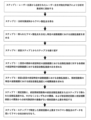
- FIG. 3 schematically shows changes in the Raman scattering spectrum before and after the sample to be analyzed by laser light is burnt.
- the sample to be analyzed receives damage such as burnout due to laser light, the baseline of the Raman scattering spectrum rises.
- the sample to be analyzed is an organic substance, a D-band around 1350 cm ⁇ 1 and a G-band around 1590 cm ⁇ 1 appear due to carbonization of carbon.
- the originally obtained Raman scattering spectrum is small and broad, which may hinder structural analysis. Since the change in the Raman scattering spectrum due to damage progresses gradually, it is difficult to determine the number of times the laser light irradiation caused the damage, based only on the change in the spectrum. In addition, if it is found that the sample to be analyzed is damaged after the Raman analysis, the analysis may become useless, or the sample to be analyzed may need to be adjusted again.
- step 3 the total scattering intensity in a specific wavenumber range is obtained in the Raman scattering spectrum obtained in step 2.
- the wavenumber range does not need to obtain the total scattering intensity for all wavenumbers;
- step 4 Obtain the total scattering intensity, Sn, in the specific wavenumber range.
- the total scattering intensity corresponds to the area surrounded by the spectrum and the horizontal axis of the spectrum diagram in the specific wavenumber range. Expressed as an integral.
- Sn represents the total scattering intensity at the time of the n-th laser beam irradiation.
- steps 1 to 3 are repeated to obtain Sn for each irradiation of laser light.
- the number of times of irradiation, n, and the total scattering intensity, Sn may be stored so that it can be called up at an appropriate time, or n and Sn may be displayed on the display device for each number of times of irradiation.
- step 5 the intensity ratio of Sn to the total scattering intensity S1 at the time of the first laser beam irradiation, s n , is obtained.
- sn is represented by the following formula (1).
- Sn may be calculated each time Sn is obtained in step 4, or s2 to sn may be calculated collectively after the Raman spectroscopic measurement is completed.
- step 6 the correlation coefficient, r, between S1 and each Sn is determined.
- r is a coefficient used in statistical processing and is a value obtained by dividing covariance by standard deviation.
- the covariance is the value obtained by dividing the deviation of Sn by the number of measurements n
- the standard deviation is the square root of the sum of the squares of the differences between the average value of the total scattering intensity obtained by n laser beam irradiations and each Sn.
- s n and r may be stored so that they can be called up at an appropriate time, or s n and r may be displayed simultaneously with n and Sn on the display device for each irradiation.
- step 7 the upper limit of n at which the sample to be analyzed is not damaged is determined from the relationship between Sn or sn and n and the relationship with r.
- the baseline of the Raman scattering spectrum rises when the sample to be analyzed is damaged. That is, Sn is constant until damage occurs, but after damage occurs, Sn increases as the baseline rises. s n similarly increases after the sample to be analyzed is damaged. Therefore, if n is specified at which Sn or sn increases, n-1 immediately preceding it becomes the upper limit of the number of times the sample to be analyzed is undamaged.
- n at which r becomes small it is possible to specify n at which the organic substance was damaged by burning.
- the number n-1 immediately before that is the upper limit of the number of times the sample to be analyzed is not damaged by burning.
- n and Sn or sn and the relationship between n and r can be determined by calling and comparing each n, Sn or sn , r whose numerical values have been stored so far, so that the sample to be analyzed is not damaged. A maximum number of times can be specified. Plotting Sn or sn against n and plotting r against n is visually helpful.
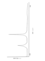
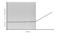
- FIGS. 4 and 5 schematically show the results when Sn or sn is plotted against n and r is plotted against n.
- Sn or sn when Sn or sn is plotted against n, the value of Sn or sn increases with respect to a certain n. n appears where the straight lines that were parallel change upward to the right. This n is the number of laser light irradiation times at which the sample to be analyzed was damaged.
- n is the number of times a new peak appears due to burnout or the like of the sample to be analyzed, and is the number of times the sample to be analyzed has been irradiated with laser light due to burnout.
- the analysis target It is possible to determine the number of laser light irradiation times at which the sample is burned, and to specify the upper limit number of times the sample to be analyzed is not burnt.
- n is the number of times of laser beam irradiation that causes Sn-Sn-1 ⁇ d or sn- s n-1 ⁇ d to cause burnout of the sample to be analyzed. A maximum number of times the sample has not suffered burnout may be specified. The same is true for r and n.
- FIG. 4 and FIG. 5 schematically show the results when Sn or sn is plotted against n and r is plotted against n, and in some cases the change is very small. Therefore, it is more accurate to identify the upper limit of the number of undamaged samples to be analyzed from the change in slope of the line by linear regression analysis of the plot of Sn or sn against n and the plot of r against n. It is preferable because the number of times can be specified.
- the number n of laser beam irradiations in which the sample to be analyzed is damaged is obtained by the above method, the number of laser beam irradiations in which the sample to be analyzed is not damaged can be specified up to the n ⁇ 1. Accurate analysis becomes possible by structural analysis of the sample to be analyzed using the data up to the first time. If each n and its Raman scattering spectrum are stored as described above, the Raman scattering spectrum up to the upper limit of the number of times of laser light irradiation at which the sample to be analyzed specified above is not damaged can be called up and analyzed.
- FIG. 6 shows a schematic diagram of a mode of a microscopic Raman spectrometer for carrying out the above analysis method.
- the microscopic Raman spectroscopic apparatus shown in FIG. 6 has a laser light source A, a microscope optical section 4, a plate 2 for fixing a sample to be analyzed, a spectroscope 5, and a Raman scattered light detection system 6.
- FIG. 6 further has a stage 3 for fixing the plate 2 and an optical imaging device 11 for displaying an image of the analysis field as a preferred embodiment.
- the microscopic Raman spectroscopic apparatus of the present invention includes a storage unit 7 for storing the number of times of laser light irradiation and the Raman scattered light spectrum at that time, and an operation for calculating the total scattering intensity of Raman scattered light in a specific wave number range for each laser light irradiation.
- Unit 81 computing unit 82 for calculating the ratio of the total scattering intensity in the specific wavenumber range of each irradiation to the total scattering intensity in the specific wavenumber range of the first irradiation, the total scattering intensity in the specific wavenumber range of the first irradiation
- a calculation unit 83 that obtains a correlation coefficient between the scattering intensity and the total scattering intensity in a specific wavenumber range for each number of times of irradiation, and the number of measurements and the total scattering intensity for each number of times of irradiation, or the A display unit that displays at least one of the relationship between the total scattering intensity in a specific wavenumber range and the ratio of the total scattering intensity in the specific wavenumber range of the number of irradiation times, and the relationship between the number of measurements and the correlation coefficient.
- the analysis unit 10 specifies the upper limit of the number of irradiations that does not damage the sample to be analyzed.
- a laser light source A is a light source for irradiating a laser beam for obtaining the Raman scattered light.
- the microscope optical part 4 can be exemplified by a structure in which an objective lens (not shown) that is a combination of a convex lens and a concave lens is combined as an objective optical element (not shown). 2 is focused on the sample to be measured.
- a Raman scattering hole reflected by the sample is guided to a spectroscope 5 and a Raman scattered light detection system 6 via a condenser lens (not shown) and a condenser spot (not shown).
- the Raman scattered light condensed by the condensing lens is focused on the condensed spot and guided to the spectroscope 5 .
- the microscope optical unit 4 which is a confocal optical system in which the positions of the light source A, the plate 2, and the focused spot are in a conjugate relationship, is preferable from the viewpoint of resolution.
- the optical imaging device 11 is, for example, a CCD (Charge Coupled Device) image sensor, a CMOS (Complementary Metal Oxide Semiconductor) image sensor, or the like, and is configured to be able to capture a still image or moving image of a sample.
- the optical imaging device can capture all or at least one of a bright-field image, a dark-field image, a phase-contrast image, a fluorescent image, a polarizing microscope image, etc. of the sample, depending on the configuration of the microscope optical unit 4 and transmitted illumination (not shown). can be imaged.
- the optical imaging device outputs the captured image to another information processing device or the like, if necessary.
- the microscopic Raman spectroscopy apparatus of the present invention has a storage unit 7 that stores the number of times of laser light irradiation, n, and the Raman scattering light spectrum at that time, Wn.
- the storage unit 7 is configured not only to store the values of n and Wn, but also to be able to call them when necessary.
- the storage unit 7 preferably stores n and Wn as a set of data.
- the microscopic Raman spectroscopic apparatus of the present invention has a computing unit 81, which is a part of the computing unit 8, for computing the total scattering intensity Sn of Raman scattered light in a specific wavenumber range for each laser beam irradiation.
- the method for obtaining Sn is as described above, and the calculation unit 81 is configured to calculate the Sn.
- the micro Raman spectroscopy apparatus of the present invention includes an arithmetic unit 82 which is a part of the arithmetic unit 8 for obtaining the ratio s n of the S 1 to Sn, and the arithmetic unit 8 for obtaining the correlation coefficient r between the S 1 and Sn has a computing unit 83 which is a part of.
- the computing units 81 to 83 may be the same computing device, or may be independent computing devices. s n and r are calculated as described above.
- Sn, s n , and r obtained by the calculation unit 8 may be sent to the storage unit 7 and stored therein.
- the display unit 9 displays the relationship between at least one of Sn or sn and the number of measurements n obtained by the arithmetic unit 8 and the relationship between n and r.
- Display methods include, for example, a method of displaying Sn or sn corresponding to n and n and r as a set, a method of displaying Sn or sn and r for n as a set, and the like. is preferably displayed by plotting Sn or sn against n and plotting r against n as described above. For example, when a diagram such as that schematically shown in FIG. 4 or 5 is displayed, it is easy to visually understand, and it is easy to determine the number of irradiation times in which the sample to be analyzed was damaged by the laser beam.
- the microscopic Raman spectroscopy apparatus of the present invention has a laser beam that does not damage the sample to be analyzed from the relationship between at least one of Sn or sn obtained by the arithmetic unit 8 and the number of measurements n, and the relationship between n and r. It has an analysis unit that specifies the upper limit of the number of times of irradiation.
- the method for specifying the upper limit of the number of times of laser light irradiation that does not damage the sample to be analyzed in the analysis unit 10 is as described above.
- the upper limit of the number of times of laser light irradiation that does not damage the obtained sample to be analyzed may be displayed on the display unit 9.
- the range of the number of times of laser light irradiation that does not damage the sample to be analyzed A plot of Sn or sn against displayed n or a plot of r against n may be displayed together.
- the plot of Sn or sn against n or the plot of r against n is displayed on the display unit 9 by displaying the range of the number of laser beam irradiations that does not damage the sample to be analyzed. You can select the range above.
- the storage unit 7 stores n, the Raman scattering spectrum, and Wn so that Wn corresponding to the range of n not damaged by the laser beam can be called from the storage unit 7.
- the display unit 9 and the analysis unit 10 may be linked with each other.
- the selection method may be such that the Raman scattering spectrum below the upper limit of the number of times of laser light irradiation that does not damage the sample to be analyzed specified by the analysis unit 10 can be automatically called from the storage unit 7, or the analyst can It may be called from the storage unit 7 by specifying the screen of the display unit 9 with a mouse or keyboard.
- the analyst selects the range, it is not necessary to specify the (n-1)th specified by the analysis unit 10, and the range may be selected by the analyst's judgment.
- the data of the Raman scattered light obtained before the sample to be analyzed is damaged by the laser light during the Raman spectroscopic measurement is determined, and only the data of the Raman scattered light before the damage is used to analyze the target Structural analysis of samples can be performed.
- the Raman spectroscopic analysis method of the present invention the data of the Raman scattered light obtained before the sample to be analyzed is damaged by the laser light during the Raman spectroscopic measurement is determined, and only the data of the Raman scattered light before the damage is obtained. Structural analysis of the sample to be analyzed can be performed. Further, according to the present invention, there is provided a microscopic Raman spectroscopic apparatus for executing the Raman spectroscopic analysis method.
- a laser light source irradiating a sample to be analyzed with an objective optical element with a laser beam emitted from a laser light source; Obtaining Raman scattered light from the sample to be analyzed, Spectroscopy the obtained Raman scattered light to determine the total scattered intensity in a specific wavenumber range, Repeating the step of obtaining the total scattering intensity in a specific wavenumber range from the irradiation of the laser light a plurality of times, Obtaining the ratio of the total scattering intensity in the specific wavenumber range of each irradiation to the total scattering intensity in the specific wavenumber range of the first irradiation, Obtaining a correlation coefficient between the total scattering intensity in the specific wavenumber range for the first time and the total scattering intensity in the specific wavenumber range for each irradiation, At least one of the number of measurements, the total scattering intensity for each of the irradiation times, or the ratio of the total scattering intensity in the specific wavenumber range for each
- the data of the Raman scattered light obtained before the sample to be analyzed is damaged by the laser light during the Raman spectroscopic measurement is determined, and only the data of the Raman scattered light before the damage is used to analyze the target.
- a method of Raman spectroscopy is provided for structural analysis of a sample.
- a laser light source ; microscope optics, a plate for fixing the sample to be analyzed; having a spectrometer, and a Raman scattered light detection system, a storage unit that stores the number of times of laser light irradiation and the Raman scattered light spectrum at that time;
- a calculation unit that calculates the total scattering intensity of Raman scattered light in a specific wavenumber range for each laser light irradiation,
- a computing unit that obtains a ratio of the total scattering intensity in the specific wavenumber range of each irradiation to the total scattering intensity in the specific wavenumber range of the first irradiation; a calculation unit for obtaining a correlation coefficient between the first total scattering intensity in the specific wavenumber range and the total scattering intensity in the specific wavenumber range for each number of times of irradiation; and At least one of the relationship between the scattering intensity or the ratio of the total scattering intensity in the
- the data of Raman scattered light obtained before the sample to be analyzed is damaged by the laser light during Mann spectrometry is determined, and only the data of Raman scattered light before damage is used to analyze the object
- a micro Raman spectroscopy apparatus capable of easily performing Raman spectroscopic analysis for structural analysis of a sample.
- the display unit indicates the number of times of measurement, the total scattering intensity for each of the irradiation times, or the total scattering intensity in the specific wavenumber range of each irradiation time with respect to the total scattering intensity in the specific wavenumber range of the first irradiation.
- the microscopic Raman spectroscopic device according to [6] above which plots and displays at least one of the ratio of intensities.
- the analysis unit measures the number of times of measurement, the total scattering intensity for each of the irradiation times, or the total scattering intensity in the specific wavenumber range of each irradiation time for the first irradiation, and the total scattering intensity in the specific wavenumber range of each irradiation time
- the microscopic Raman spectroscopic device according to any one of [6] to [8], wherein linear regression analysis is performed on at least one plot of the scattering intensity ratio to specify the upper limit of the number of irradiations without damaging the sample to be analyzed. .
Abstract
Description
しかしながら焼損した部分は構造が壊れているため、同じ場所を測定しても本来の構造を反映したラマン散乱光を得ることはできない。 When a sample burns out, the structure of the sample to be analyzed changes, making it impossible to obtain Raman scattered light data based on the original structure. Therefore, it is necessary to measure the Raman scattered light again for accurate structural analysis. There is
However, since the structure of the burnt-out part is broken, it is impossible to obtain Raman scattered light reflecting the original structure even if the same place is measured.
さらに本発明は前記ラマン分光分析方法を実行する顕微ラマン分光装置の提供を目的とする。 The present invention specifies the number of laser light irradiation times at which a sample to be analyzed is damaged by laser light during multiple Raman spectroscopic measurements, and uses Raman scattered light data obtained when the sample to be analyzed is in an undamaged state. An object of the present invention is to provide a Raman spectroscopic analysis method for structural analysis of a sample to be analyzed.
A further object of the present invention is to provide a microscopic Raman spectroscopic apparatus for performing the Raman spectroscopic analysis method.
レーザー光源から出射されたレーザー光を対物光学素子により分析対象試料に照射し、
分析対象試料からラマン散乱光を得、
前記得られたラマン散乱光を分光し特定の波数範囲における全散乱強度を求め、
前記レーザー光の照射から特定の波数範囲における全散乱強度を求める工程を複数回繰り返し、
1回目の照射の前記特定の波数範囲における全散乱強度に対する各照射の前記特定の波数範囲における前記全散乱強度の比を求め、
前記1回目の前記特定の波数範囲における全散乱強度と、照射回数毎の特定の波数範囲における前記全散乱強度との相関係数を求め、
測定回数と、前記照射回数毎の前記全散乱強度、または1回目の照射の前記特定の波数範囲における全散乱強度に対する各照射回数の前記特定の波数範囲における前記全散乱強度の比、の少なくともいずれかの関係、および
前記測定回数と前記相関係数との関係
から分析対象試料の損傷がない照射回数の上限を特定し、
前記上限の照射回数までのラマン散乱光のデータを用いるラマン分光分析方法、
を提供する。 That is, the present invention
irradiating a sample to be analyzed with an objective optical element with a laser beam emitted from a laser light source;
Obtaining Raman scattered light from the sample to be analyzed,
Spectroscopy the obtained Raman scattered light to determine the total scattered intensity in a specific wavenumber range,
Repeating the step of obtaining the total scattering intensity in a specific wavenumber range from the irradiation of the laser light a plurality of times,
Obtaining the ratio of the total scattering intensity in the specific wavenumber range of each irradiation to the total scattering intensity in the specific wavenumber range of the first irradiation,
Obtaining a correlation coefficient between the total scattering intensity in the specific wavenumber range for the first time and the total scattering intensity in the specific wavenumber range for each irradiation,
At least one of the number of measurements, the total scattering intensity for each of the irradiation times, or the ratio of the total scattering intensity in the specific wavenumber range for each irradiation time to the total scattering intensity in the specific wavenumber range for the first irradiation. and from the relationship between the number of measurements and the correlation coefficient, the upper limit of the number of times of irradiation without damage to the sample to be analyzed is specified,
Raman spectroscopic analysis method using Raman scattered light data up to the upper limit number of irradiations,
I will provide a.
レーザー光源、
顕微鏡光学部、
分析対象試料を固定するプレート、
分光器、おおびラマン散乱光検出系を有し、
レーザー光照射の回数、その時のラマン散乱光スペクトルを記憶する記憶部、
レーザー光照射毎の特定の波数範囲におけるラマン散乱光の全散乱強度を演算する演算部、
1回目の照射の前記特定の波数範囲における全散乱強度に対する各照射の前記特定の波数範囲における前記全散乱強度の比を求める演算部、
前記1回目の前記特定の波数範囲における全散乱強度と、照射回数毎の特定の波数範囲における前記全散乱強度との相関係数を求める演算部、および
測定回数と、前記照射回数毎の前記全散乱強度、または1回目の照射の前記特定の波数範囲における全散乱強度に対する各照射回数の前記特定の波数範囲における前記全散乱強度の比、の少なくともいずれかの関係、および
前記測定回数と前記相関係数との関係を表示する表示部、
前記測定回数と、前記照射回数毎の前記全散乱強度、または1回目の照射の前記特定の波数範囲における全散乱強度に対する各照射回数の前記特定の波数範囲における前記全散乱強度の比、の少なくともいずれかの関係、および
前記測定回数と前記相関係数との関係から分析対象試料の損傷がない照射回数の上限を特定する解析部
を有する顕微ラマン分光装置、
を提供する。 Further, the present invention
laser light source,
microscope optics,
a plate for fixing the sample to be analyzed;
having a spectrometer, and a Raman scattered light detection system,
a storage unit that stores the number of times of laser light irradiation and the Raman scattered light spectrum at that time;
A calculation unit that calculates the total scattering intensity of Raman scattered light in a specific wavenumber range for each laser light irradiation,
A computing unit that obtains a ratio of the total scattering intensity in the specific wavenumber range of each irradiation to the total scattering intensity in the specific wavenumber range of the first irradiation;
a calculation unit for obtaining a correlation coefficient between the first total scattering intensity in the specific wavenumber range and the total scattering intensity in the specific wavenumber range for each number of times of irradiation; and At least one of the relationship between the scattering intensity or the ratio of the total scattering intensity in the specific wavenumber range of each irradiation time to the total scattering intensity in the specific wavenumber range of the first irradiation, and the number of measurements and the phase a display unit that displays the relationship with the coefficient of correlation;
At least the number of measurements, the total scattering intensity for each of the irradiation times, or the ratio of the total scattering intensity in the specific wavenumber range of each irradiation time to the total scattering intensity in the specific wavenumber range of the first irradiation. A microscopic Raman spectroscopic device having an analysis unit that specifies the upper limit of the number of times of irradiation without damaging the sample to be analyzed from any relationship and the relationship between the number of measurements and the correlation coefficient;
I will provide a.
さらに本発明によれば、前記ラマン分光分析方法を実行する顕微ラマン分光装置が提供される。 According to the present invention, the data of Raman scattered light obtained before the sample to be analyzed is damaged by laser light during Raman spectroscopy is identified, and the structure of the sample to be analyzed is analyzed only from the data of Raman scattered light before damage. A method of Raman spectroscopy is provided.
Further, according to the present invention, there is provided a microscopic Raman spectroscopic apparatus for executing the Raman spectroscopic analysis method.
ステップ1および2はレーザー光を対物光学素子により分析対象試料の所望の分析対象領域にレーザー光を照射し、分析対象試料からのラマン散乱光を得、得られたラマン散乱光を分光することで波長または波数に対して図2で模式的に示したようにラマンスペクトルが得られる。 FIG. 1 is a flow chart showing the Raman spectroscopic analysis method of the present invention using a microscopic Raman spectrometer.
また顕微ラマンによる分析の場合、対物光学素子により局所にレーザー光が集中的に照射されるため、分析対象試料の焼損が顕著となる。 However, if
In addition, in the case of microscopic Raman analysis, since laser light is locally irradiated intensively by the objective optical element, burning of the sample to be analyzed becomes significant.
図3に示したように、レーザー光による焼損等の損傷を分析対象試料が受けた場合、ラマン散乱スペクトルのベースラインが上昇する。また分析対象試料が有機物の場合、炭素の炭化による1350cm-1付近のD-bandおよび1590cm-1付近のG-bandが出現する。その結果、本来得られるラマン散乱スペクトルが小さく、またブロードとなり構造解析に支障をきたす場合がある。
損傷によるラマン散乱スペクトルの変化は徐々に進行するため、何回目のレーザー光の照射で損傷が起こったかをスペクトルの変化のみから特定するのは困難である。またラマン分析後に分析対象試料が損傷していることが判明することで、その分析が無駄となる場合や、再度の分析対象試料の調整が必要となる場合がある。 FIG. 3 schematically shows changes in the Raman scattering spectrum before and after the sample to be analyzed by laser light is burnt.
As shown in FIG. 3, when the sample to be analyzed receives damage such as burnout due to laser light, the baseline of the Raman scattering spectrum rises. Also, when the sample to be analyzed is an organic substance, a D-band around 1350 cm −1 and a G-band around 1590 cm −1 appear due to carbonization of carbon. As a result, the originally obtained Raman scattering spectrum is small and broad, which may hinder structural analysis.
Since the change in the Raman scattering spectrum due to damage progresses gradually, it is difficult to determine the number of times the laser light irradiation caused the damage, based only on the change in the spectrum. In addition, if it is found that the sample to be analyzed is damaged after the Raman analysis, the analysis may become useless, or the sample to be analyzed may need to be adjusted again.
ステップ4では前記ステップ1からステップ3を繰り返し、レーザー光の照射毎にSnを求める。この時、照射回数、n、全散乱強度、Sn、を記憶し適切な時に呼び出せるようにしておくか、照射回数毎に表示装置にnおよびSnを表示させてもよい。 Obtain the total scattering intensity, Sn, in the specific wavenumber range. The total scattering intensity corresponds to the area surrounded by the spectrum and the horizontal axis of the spectrum diagram in the specific wavenumber range. Expressed as an integral. Note that Sn represents the total scattering intensity at the time of the n-th laser beam irradiation.
In step 4,
sn=Sn/S1 (1)
ステップ5は前記ステップ4でSnを求める毎に計算により求めてもよいし、ラマン分光測定が完了した後、まとめてs2からsnまで計算してもよい。 Further, in
s n =Sn/S 1 (1)
In
共分散はSnの偏差を測定回数nで除した値であり、標準偏差はn回のレーザー光照射で得られる全散乱強度の平均値と各Snとの差の二乗の総和の平方根である。
前記nおよびSnと同様、前記snおよびrを記憶し適切な時に呼び出せるようにしておくか、照射回数毎に表示装置にnおよびSnと同時にsn、rを表示させてもよい。 In
The covariance is the value obtained by dividing the deviation of Sn by the number of measurements n, and the standard deviation is the square root of the sum of the squares of the differences between the average value of the total scattering intensity obtained by n laser beam irradiations and each Sn.
As with n and Sn, s n and r may be stored so that they can be called up at an appropriate time, or s n and r may be displayed simultaneously with n and Sn on the display device for each irradiation.
図3に示したとおり、分析対象試料が損傷を受けるとラマン散乱スペクトルのベースラインが上昇する。すなわち損傷を受けるまではSnは一定であるが、損傷を受けた後はベースラインが上昇した分、Snは大きくなる。snも同様に分析対象試料が損傷を受けた後は大きくなる。したがって、Snまたはsnが大きくなるnを特定すれば、その直前のn-1が分析対象試料が損傷を受けていない上限の回数となる。 In
As shown in FIG. 3, the baseline of the Raman scattering spectrum rises when the sample to be analyzed is damaged. That is, Sn is constant until damage occurs, but after damage occurs, Sn increases as the baseline rises. s n similarly increases after the sample to be analyzed is damaged. Therefore, if n is specified at which Sn or sn increases, n-1 immediately preceding it becomes the upper limit of the number of times the sample to be analyzed is undamaged.
したがって、rが小さくなるnを特定することで、焼損による有機物の損傷を受けたnを特定することができる。その直前のn-1が分析対象試料が焼損を受けていない上限の回数となる。 Furthermore, as shown in FIG. 3, when the sample to be analyzed is an organic substance, a D-band near 1350 cm −1 and a G-band near 1590 cm −1 appear due to carbonization of carbon. As a result, Sn or sn increases as the baseline rises, while r does not decrease due to the influence of a new peak that appears due to burnout or the like.
Therefore, by specifying n at which r becomes small, it is possible to specify n at which the organic substance was damaged by burning. The number n-1 immediately before that is the upper limit of the number of times the sample to be analyzed is not damaged by burning.
図4に示したように、nに対してSnまたはsnをプロットした場合、あるnに対してSnまたはsnの値が大きくなり、各点を直線で結んだ場合、x軸に対して平行であった直線が右肩上がりに変化するnが出現する。このnが分析対象試料が損傷を受けたレーザー光の照射回数である。 FIGS. 4 and 5 schematically show the results when Sn or sn is plotted against n and r is plotted against n.
As shown in FIG. 4, when Sn or sn is plotted against n, the value of Sn or sn increases with respect to a certain n. n appears where the straight lines that were parallel change upward to the right. This n is the number of laser light irradiation times at which the sample to be analyzed was damaged.
またはある閾値dを予め決めておき、Sn-Sn-1≧dまたはsn-sn-1≧dとなるようなnを分析対象試料が焼損を受けたレーザー光の照射回数とし、分析対象試料が焼損を受けていない上限の回数を特定してもよい。
rとnについても同様である。 That is, when the sample to be analyzed is damaged, there is n at which the value of Sn or sn increases. Therefore, by comparing Sn with the previous Sn-1, or s n with the previous s n-1 , and finding n that satisfies Sn-1 < Sn or s n-1 < s n , the analysis target It is possible to determine the number of laser light irradiation times at which the sample is burned, and to specify the upper limit number of times the sample to be analyzed is not burnt.
Alternatively, a certain threshold value d is determined in advance, and n is the number of times of laser beam irradiation that causes Sn-Sn-1 ≥ d or sn- s n-1 ≥ d to cause burnout of the sample to be analyzed. A maximum number of times the sample has not suffered burnout may be specified.
The same is true for r and n.
前記のとおり各nとそのラマン散乱スペクトルとを記憶させておけば、前記で特定した分析対象試料が損傷を受けていないレーザー光の照射回数の上限までのラマン散乱スペクトルを呼び出し分析すればよい。 If the number n of laser beam irradiations in which the sample to be analyzed is damaged is obtained by the above method, the number of laser beam irradiations in which the sample to be analyzed is not damaged can be specified up to the n−1. Accurate analysis becomes possible by structural analysis of the sample to be analyzed using the data up to the first time.
If each n and its Raman scattering spectrum are stored as described above, the Raman scattering spectrum up to the upper limit of the number of times of laser light irradiation at which the sample to be analyzed specified above is not damaged can be called up and analyzed.
図6に示した顕微ラマン分光装置は、レーザー光源A、顕微鏡光学部4、分析対象試料を固定するプレート2、分光器5、おおびラマン散乱光検出系6を有している。図6はさらにこのましい態様としてプレート2を固定するステージ3、分析視野を画像で表示する光学撮影素子11を有している。 FIG. 6 shows a schematic diagram of a mode of a microscopic Raman spectrometer for carrying out the above analysis method.
The microscopic Raman spectroscopic apparatus shown in FIG. 6 has a laser light source A, a microscope optical section 4, a
顕微鏡光学部4は対物光学素子(図示せず)として凸レンズと凹レンズを組み合わせた対物レンズ(図示せず)を組み合わせた構成が例示でき、顕微鏡光学部3に入射した光はこれら対物光学素子によりプレート2に固定された測定対象試料上に焦点を結ぶ。
サンプルにより反射したラマン散乱孔は集光レンズ(図示せず)および集光スポット(図示せず)を経て分光器5、ラマン散乱光検出系6に導かれる。集光レンズにより集光されたラマン散乱光は集光スポット上で焦点を結び分光器5に導かれる。
この時、光源A、プレート2、集光スポットの位置が共役関係にある共焦点光学系となる顕微鏡光学部4が解像度の観点から好ましい。 A laser light source A is a light source for irradiating a laser beam for obtaining the Raman scattered light.
The microscope optical part 4 can be exemplified by a structure in which an objective lens (not shown) that is a combination of a convex lens and a concave lens is combined as an objective optical element (not shown). 2 is focused on the sample to be measured.
A Raman scattering hole reflected by the sample is guided to a
At this time, the microscope optical unit 4, which is a confocal optical system in which the positions of the light source A, the
前記演算部81から83は同一の演算装置ともよいし、それぞれが独立した演算装置でもよい。
snおよびrの計算方法は前記のとおりである。 Further, the micro Raman spectroscopy apparatus of the present invention includes an
The
s n and r are calculated as described above.
例えば図4または図5に模式的に示したような図を表示すると視覚的に分かりやすく、分析対象試料がレーザー光によって損傷を受けた照射回数が判別しやすい。 The display unit 9 displays the relationship between at least one of Sn or sn and the number of measurements n obtained by the
For example, when a diagram such as that schematically shown in FIG. 4 or 5 is displayed, it is easy to visually understand, and it is easy to determine the number of irradiation times in which the sample to be analyzed was damaged by the laser beam.
解析部10での分析対象試料の損傷がないレーザー光の照射回数の上限を特定する方法は前記のとおりである。得られた分析対象試料の損傷がないレーザー光の照射回数の上限を前記表示部9に表示させてもよく、例えば分析対象試料の損傷がないレーザー光の照射回数の範囲を、表示部9で表示させたnに対するSnまたはsnのプロット、またはnに対するrのプロットともに表示させてもよい。 Further, the microscopic Raman spectroscopy apparatus of the present invention has a laser beam that does not damage the sample to be analyzed from the relationship between at least one of Sn or sn obtained by the
The method for specifying the upper limit of the number of times of laser light irradiation that does not damage the sample to be analyzed in the
表示部9の画面上で範囲を選択することで、nおよびラマン散乱スペクトル、Wnを記憶する記憶部7からレーザー光によって損傷を受けていないnの範囲に相当するWnを呼び出せるよう、記憶部7と表示部9および解析部10を連動させてもよい。選択の方法は解析部10で特定された分析対象試料の損傷がないレーザー光の照射回数の上限値以下のラマン散乱スペクトルを自動的に記憶部7から呼び出せるようにしてもよいし、分析者が表示部9の画面上をマウスまたはキーボードにより指定する等の方法で記憶部7から呼び出してもよい。
分析者が範囲を選択する場合、必ずしも前記解析部10で特定されたn-1回目を指定する必要はなく、分析者の判断で範囲を選択出来るようにしてもよい。 As described above, the plot of Sn or sn against n or the plot of r against n is displayed on the display unit 9 by displaying the range of the number of laser beam irradiations that does not damage the sample to be analyzed. You can select the range above.
By selecting a range on the screen of the display unit 9, the
When the analyst selects the range, it is not necessary to specify the (n-1)th specified by the
さらに本発明によれば、前記ラマン分光分析方法を実行する顕微ラマン分光装置が提供される。 According to the Raman spectroscopic analysis method of the present invention, the data of the Raman scattered light obtained before the sample to be analyzed is damaged by the laser light during the Raman spectroscopic measurement is determined, and only the data of the Raman scattered light before the damage is obtained. Structural analysis of the sample to be analyzed can be performed.
Further, according to the present invention, there is provided a microscopic Raman spectroscopic apparatus for executing the Raman spectroscopic analysis method.
前記例示的な実施形態は、以下の態様の具体例であることが当業者により理解される。 [Aspect]
It will be appreciated by those skilled in the art that the exemplary embodiments are specific examples of the following aspects.
レーザー光源から出射されたレーザー光を対物光学素子により分析対象試料に照射し、
分析対象試料からラマン散乱光を得、
前記得られたラマン散乱光を分光し特定の波数範囲における全散乱強度を求め、
前記レーザー光の照射から特定の波数範囲における全散乱強度を求める工程を複数回繰り返し、
1回目の照射の前記特定の波数範囲における全散乱強度に対する各照射の前記特定の波数範囲における前記全散乱強度の比を求め、
前記1回目の前記特定の波数範囲における全散乱強度と、照射回数毎の特定の波数範囲における前記全散乱強度との相関係数を求め、
測定回数と、前記照射回数毎の前記全散乱強度、または1回目の照射の前記特定の波数範囲における全散乱強度に対する各照射回数の前記特定の波数範囲における前記全散乱強度の比、の少なくともいずれかの関係、および
前記測定回数と前記相関係数との関係
から分析対象試料の損傷がない照射回数の上限を特定し、
前記上限の照射回数までのラマン散乱光のデータを用いるラマン分光分析方法。 [1] a laser light source;
irradiating a sample to be analyzed with an objective optical element with a laser beam emitted from a laser light source;
Obtaining Raman scattered light from the sample to be analyzed,
Spectroscopy the obtained Raman scattered light to determine the total scattered intensity in a specific wavenumber range,
Repeating the step of obtaining the total scattering intensity in a specific wavenumber range from the irradiation of the laser light a plurality of times,
Obtaining the ratio of the total scattering intensity in the specific wavenumber range of each irradiation to the total scattering intensity in the specific wavenumber range of the first irradiation,
Obtaining a correlation coefficient between the total scattering intensity in the specific wavenumber range for the first time and the total scattering intensity in the specific wavenumber range for each irradiation,
At least one of the number of measurements, the total scattering intensity for each of the irradiation times, or the ratio of the total scattering intensity in the specific wavenumber range for each irradiation time to the total scattering intensity in the specific wavenumber range for the first irradiation. and from the relationship between the number of measurements and the correlation coefficient, the upper limit of the number of times of irradiation without damage to the sample to be analyzed is specified,
A Raman spectroscopic analysis method using Raman scattered light data up to the upper limit number of times of irradiation.
[3] 前記測定回数と前記相関係数とをプロットする前記[1]または[2]に記載のラマン分光分析方法。 [2] The number of measurements, the total scattering intensity for each of the irradiation times, or the ratio of the total scattering intensity in the specific wavenumber range for each irradiation time to the total scattering intensity in the specific wavenumber range for the first irradiation, The Raman spectroscopic analysis method according to the above [1], wherein at least one of the above is plotted.
[3] The Raman spectroscopic analysis method according to [1] or [2], wherein the number of measurements and the correlation coefficient are plotted.
[5] 前記測定回数と前記相関係数とのプロットの直線回帰分析を行ない、傾きが変化する測定回数から分析対象試料の損傷がない照射回数の上限と特定する前記[4]に記載のラマン分光分析方法。 [4] The number of measurements, the total scattering intensity for each of the irradiation times, or the ratio of the total scattering intensity in the specific wavenumber range for each irradiation time to the total scattering intensity in the specific wavenumber range for the first irradiation, The Raman spectroscopic analysis method according to the above [2], wherein linear regression analysis is performed on at least one of the plots, and the upper limit of the number of irradiations without damage to the sample to be analyzed is specified from the number of measurements at which the slope changes.
[5] The Raman according to [4], wherein linear regression analysis is performed on the plot of the number of measurements and the correlation coefficient, and the upper limit of the number of irradiations without damage to the sample to be analyzed is determined from the number of measurements where the slope changes. Spectroscopic method.
[6] レーザー光源、
顕微鏡光学部、
分析対象試料を固定するプレート、
分光器、おおびラマン散乱光検出系を有し、
レーザー光照射の回数、その時のラマン散乱光スペクトルを記憶する記憶部、
レーザー光照射毎の特定の波数範囲におけるラマン散乱光の全散乱強度を演算する演算部、
1回目の照射の前記特定の波数範囲における全散乱強度に対する各照射の前記特定の波数範囲における前記全散乱強度の比を求める演算部、
前記1回目の前記特定の波数範囲における全散乱強度と、照射回数毎の特定の波数範囲における前記全散乱強度との相関係数を求める演算部、および
測定回数と、前記照射回数毎の前記全散乱強度、または1回目の照射の前記特定の波数範囲における全散乱強度に対する各照射回数の前記特定の波数範囲における前記全散乱強度の比、の少なくともいずれかの関係、および
前記測定回数と前記相関係数との関係を表示する表示部、
前記測定回数と、前記照射回数毎の前記全散乱強度、または1回目の照射の前記特定の波数範囲における全散乱強度に対する各照射回数の前記特定の波数範囲における前記全散乱強度の比、の少なくともいずれかの関係、および
前記測定回数と前記相関係数との関係から分析対象試料の損傷がない照射回数の上限を特定する解析部
を有する顕微ラマン分光装置。 It will also be understood by those skilled in the art that the exemplary embodiments are specific examples of the following aspects.
[6] a laser light source;
microscope optics,
a plate for fixing the sample to be analyzed;
having a spectrometer, and a Raman scattered light detection system,
a storage unit that stores the number of times of laser light irradiation and the Raman scattered light spectrum at that time;
A calculation unit that calculates the total scattering intensity of Raman scattered light in a specific wavenumber range for each laser light irradiation,
A computing unit that obtains a ratio of the total scattering intensity in the specific wavenumber range of each irradiation to the total scattering intensity in the specific wavenumber range of the first irradiation;
a calculation unit for obtaining a correlation coefficient between the first total scattering intensity in the specific wavenumber range and the total scattering intensity in the specific wavenumber range for each number of times of irradiation; and At least one of the relationship between the scattering intensity or the ratio of the total scattering intensity in the specific wavenumber range of each irradiation time to the total scattering intensity in the specific wavenumber range of the first irradiation, and the number of measurements and the phase a display unit that displays the relationship with the coefficient of correlation;
At least the number of measurements, the total scattering intensity for each of the irradiation times, or the ratio of the total scattering intensity in the specific wavenumber range of each irradiation time to the total scattering intensity in the specific wavenumber range of the first irradiation. A microscopic Raman spectroscopic apparatus having an analysis unit that specifies the upper limit of the number of times of irradiation without damaging a sample to be analyzed from any of the relationships and the relationship between the number of times of measurement and the correlation coefficient.
[8] 前記表示部が測定回数と、前記相関係数をプロットして表示する前記[6]または[7]に記載の顕微ラマン分光装置。 [7] The display unit indicates the number of times of measurement, the total scattering intensity for each of the irradiation times, or the total scattering intensity in the specific wavenumber range of each irradiation time with respect to the total scattering intensity in the specific wavenumber range of the first irradiation. The microscopic Raman spectroscopic device according to [6] above, which plots and displays at least one of the ratio of intensities.
[8] The microscopic Raman spectroscopic device according to [6] or [7], wherein the display unit plots and displays the number of measurements and the correlation coefficient.
[10] 前記解析部が前記測定回数と前記相関係数とのプロットの直線回帰分析を行なって分析対象試料の損傷がない照射回数の上限を特定する前記[6]から[9]のいずれかに記載の顕微ラマン分光装置。
[11] さらに分析対象試料の損傷がない照射回数のラマン散乱スペクトルを前記記憶部から呼出し表示させる機能を有する前記[6]から[10]に記載の顕微ラマン分光装置。 [9] The analysis unit measures the number of times of measurement, the total scattering intensity for each of the irradiation times, or the total scattering intensity in the specific wavenumber range of each irradiation time for the first irradiation, and the total scattering intensity in the specific wavenumber range of each irradiation time The microscopic Raman spectroscopic device according to any one of [6] to [8], wherein linear regression analysis is performed on at least one plot of the scattering intensity ratio to specify the upper limit of the number of irradiations without damaging the sample to be analyzed. .
[10] Any one of the above [6] to [9], wherein the analysis unit performs linear regression analysis of a plot of the number of measurements and the correlation coefficient to identify the upper limit of the number of irradiations that does not damage the sample to be analyzed. Microscopic Raman spectroscopic device according to.
[11] The microscopic Raman spectroscopy device according to any one of [6] to [10], further having a function of displaying Raman scattering spectra of the number of times of irradiation in which the sample to be analyzed is not damaged.
2:プレート
3:ステージ
4:顕微鏡光学部
5:分光器
6:ラマン散乱光検出系
7:記憶部
8:演算部
81:演算部
82:演算部
83:演算部
9:表示部
10:解析部
11:光学撮影素子
A:レーザー光源 1: Microscopic Raman spectroscopic device 2: Plate 3: Stage 4: Microscope optical unit 5: Spectroscope 6: Raman scattered light detection system 7: Storage unit 8: Calculation unit 81: Calculation unit 82: Calculation unit 83: Calculation unit 9: Display unit 10: analysis unit 11: optical imaging device A: laser light source
Claims (11)
- レーザー光源から出射されたレーザー光を対物光学素子により分析対象試料に照射し、
分析対象試料からラマン散乱光を得、
前記得られたラマン散乱光を分光し特定の波数範囲における全散乱強度を求め、
前記レーザー光の照射から特定の波数範囲における全散乱強度を求める工程を複数回繰り返し、
1回目の照射の前記特定の波数範囲における全散乱強度に対する各照射の前記特定の波数範囲における前記全散乱強度の比を求め、
前記1回目の前記特定の波数範囲における全散乱強度と、照射回数毎の特定の波数範囲における前記全散乱強度との相関係数を求め、
測定回数と、前記照射回数毎の前記全散乱強度、または1回目の照射の前記特定の波数範囲における全散乱強度に対する各照射回数の前記特定の波数範囲における前記全散乱強度の比、の少なくともいずれかの関係、および
前記測定回数と前記相関係数との関係から分析対象試料の損傷がない照射回数の上限を特定し、
前記上限の照射回数までのラマン散乱光のデータを用いるラマン分光分析方法。 irradiating a sample to be analyzed with an objective optical element with a laser beam emitted from a laser light source;
Obtaining Raman scattered light from the sample to be analyzed,
Spectroscopy the obtained Raman scattered light to determine the total scattered intensity in a specific wavenumber range,
Repeating the step of obtaining the total scattering intensity in a specific wavenumber range from the irradiation of the laser light a plurality of times,
Obtaining the ratio of the total scattering intensity in the specific wavenumber range of each irradiation to the total scattering intensity in the specific wavenumber range of the first irradiation,
Obtaining a correlation coefficient between the total scattering intensity in the specific wavenumber range for the first time and the total scattering intensity in the specific wavenumber range for each irradiation,
At least one of the number of measurements, the total scattering intensity for each of the irradiation times, or the ratio of the total scattering intensity in the specific wavenumber range for each irradiation time to the total scattering intensity in the specific wavenumber range for the first irradiation. and from the relationship between the number of measurements and the correlation coefficient, the upper limit of the number of times of irradiation without damage to the sample to be analyzed is specified,
A Raman spectroscopic analysis method using Raman scattered light data up to the upper limit number of times of irradiation. - 測定回数と、前記照射回数毎の前記全散乱強度、または1回目の照射の前記特定の波数範囲における全散乱強度に対する各照射回数の前記特定の波数範囲における前記全散乱強度の比、の少なくともいずれかをプロットする請求項1に記載のラマン分光分析方法。 At least one of the number of measurements, the total scattering intensity for each of the irradiation times, or the ratio of the total scattering intensity in the specific wavenumber range for each irradiation time to the total scattering intensity in the specific wavenumber range for the first irradiation. 2. The method of Raman spectroscopic analysis according to claim 1, wherein plotting is performed.
- 前記測定回数と前記相関係数とをプロットする請求項1または2に記載のラマン分光分析方法。 The Raman spectroscopic analysis method according to claim 1 or 2, wherein the number of measurements and the correlation coefficient are plotted.
- 測定回数と、前記照射回数毎の前記全散乱強度、または1回目の照射の前記特定の波数範囲における全散乱強度に対する各照射回数の前記特定の波数範囲における前記全散乱強度の比、の少なくともいずれかのプロットの直線回帰分析を行ない、傾きが変化する測定回数から分析対象試料の損傷がない照射回数の上限と特定する請求項2に記載のラマン分光分析方法。 At least one of the number of measurements, the total scattering intensity for each of the irradiation times, or the ratio of the total scattering intensity in the specific wavenumber range for each irradiation time to the total scattering intensity in the specific wavenumber range for the first irradiation. 3. The method of Raman spectroscopic analysis according to claim 2, wherein the plot is subjected to linear regression analysis, and the upper limit of the number of times of irradiation without damage to the sample to be analyzed is specified from the number of measurements at which the slope changes.
- 前記測定回数と前記相関係数とのプロットの直線回帰分析を行ない、傾きが変化する測定回数を分析対象試料の損傷がない照射回数の上限と特定する請求項3に記載のラマン分光分析方法。 The Raman spectroscopic analysis method according to claim 3, wherein linear regression analysis is performed on the plot of the number of measurements and the correlation coefficient, and the number of measurements at which the slope changes is specified as the upper limit of the number of irradiations that does not damage the sample to be analyzed.
- レーザー光源、
顕微鏡光学部、
分析対象試料を固定するプレート、
分光器、おおびラマン散乱光検出系を有し、
レーザー光照射の回数、その時のラマン散乱光スペクトルを記憶する記憶部、
レーザー光照射毎の特定の波数範囲におけるラマン散乱光の全散乱強度を演算する演算部、
1回目の照射の前記特定の波数範囲における全散乱強度に対する各照射の前記特定の波数範囲における前記全散乱強度の比を求める演算部、
前記1回目の前記特定の波数範囲における全散乱強度と、照射回数毎の特定の波数範囲における前記全散乱強度との相関係数を求める演算部、および
測定回数と、前記照射回数毎の前記全散乱強度、または1回目の照射の前記特定の波数範囲における全散乱強度に対する各照射回数の前記特定の波数範囲における前記全散乱強度の比、の少なくともいずれかの関係、および
前記測定回数と前記相関係数との関係を表示する表示部、
前記測定回数と、前記照射回数毎の前記全散乱強度、または1回目の照射の前記特定の波数範囲における全散乱強度に対する各照射回数の前記特定の波数範囲における前記全散乱強度の比、の少なくともいずれかの関係、および
前記測定回数と前記相関係数との関係
から分析対象試料の損傷がない照射回数の上限を特定する解析部
を有する顕微ラマン分光装置。 laser light source,
microscope optics,
a plate for fixing the sample to be analyzed;
having a spectrometer, and a Raman scattered light detection system,
a storage unit that stores the number of times of laser light irradiation and the Raman scattered light spectrum at that time;
A calculation unit that calculates the total scattering intensity of Raman scattered light in a specific wavenumber range for each laser light irradiation,
A computing unit that obtains a ratio of the total scattering intensity in the specific wavenumber range of each irradiation to the total scattering intensity in the specific wavenumber range of the first irradiation;
a calculation unit for obtaining a correlation coefficient between the first total scattering intensity in the specific wavenumber range and the total scattering intensity in the specific wavenumber range for each number of times of irradiation; and At least one of the relationship between the scattering intensity or the ratio of the total scattering intensity in the specific wavenumber range of each irradiation time to the total scattering intensity in the specific wavenumber range of the first irradiation, and the number of measurements and the phase a display unit that displays the relationship with the coefficient of correlation;
At least the number of measurements, the total scattering intensity for each of the irradiation times, or the ratio of the total scattering intensity in the specific wavenumber range of each irradiation time to the total scattering intensity in the specific wavenumber range of the first irradiation. A microscopic Raman spectroscopic apparatus having an analysis unit that specifies the upper limit of the number of times of irradiation that does not damage a sample to be analyzed from any of the relationships and the relationship between the number of times of measurement and the correlation coefficient. - 前記表示部が測定回数と、前記照射回数毎の前記全散乱強度、または1回目の照射の前記特定の波数範囲における全散乱強度に対する各照射回数の前記特定の波数範囲における前記全散乱強度の比、の少なくともいずれかをプロットして表示する請求項6に記載の顕微ラマン分光装置。 The display unit indicates the number of times of measurement, the total scattering intensity for each of the irradiation times, or the ratio of the total scattering intensity in the specific wavenumber range of each irradiation time to the total scattering intensity in the specific wavenumber range of the first irradiation. 7. The microscopic Raman spectrometer according to claim 6, wherein at least one of , is plotted and displayed.
- 前記表示部が測定回数と、前記相関係数をプロットして表示する請求項6または7に記載の顕微ラマン分光装置。 The microscopic Raman spectroscopic device according to claim 6 or 7, wherein the display unit plots and displays the number of measurements and the correlation coefficient.
- 前記解析部が前記測定回数と、前記照射回数毎の前記全散乱強度、または1回目の照射の前記特定の波数範囲における全散乱強度に対する各照射回数の前記特定の波数範囲における前記全散乱強度の比、の少なくともいずれかのプロットの直線回帰分析を行なって分析対象試料の損傷がない照射回数の上限を特定する請求項6から8のいずれか1項に記載の顕微ラマン分光装置。 The analysis unit calculates the number of measurements, the total scattering intensity for each number of irradiations, or the total scattering intensity in the specific wavenumber range for each number of irradiations with respect to the total scattering intensity in the specific wavenumber range for the first irradiation. 9. The microscopic Raman spectroscopic apparatus according to any one of claims 6 to 8, wherein linear regression analysis is performed on plots of at least one of the ratios, and the upper limit of the number of times of irradiation that does not damage the sample to be analyzed is specified.
- 前記解析部が前記測定回数と前記相関係数とのプロットの直線回帰分析を行なって分析対象試料の損傷がない照射回数の上限を特定する請求項6から9のいずれか1項に記載の顕微ラマン分光装置。 10. The microscope according to any one of claims 6 to 9, wherein the analysis unit performs linear regression analysis of a plot of the number of measurements and the correlation coefficient to specify the upper limit of the number of irradiations that does not damage the sample to be analyzed. Raman spectrometer.
- さらに分析対象試料の損傷がない照射回数のラマン散乱スペクトルを前記記憶部から呼出し表示させる機能を有する請求項6から10に記載の顕微ラマン分光装置。 The microscopic Raman spectroscopic apparatus according to any one of claims 6 to 10, further comprising a function of calling up and displaying the Raman scattering spectrum of the number of times of irradiation in which the sample to be analyzed is not damaged.
Priority Applications (1)
| Application Number | Priority Date | Filing Date | Title |
|---|---|---|---|
| JP2023543648A JPWO2023026523A1 (en) | 2021-08-26 | 2022-03-03 |
Applications Claiming Priority (2)
| Application Number | Priority Date | Filing Date | Title |
|---|---|---|---|
| JP2021138263 | 2021-08-26 | ||
| JP2021-138263 | 2021-08-26 |
Publications (1)
| Publication Number | Publication Date |
|---|---|
| WO2023026523A1 true WO2023026523A1 (en) | 2023-03-02 |
Family
ID=85322615
Family Applications (1)
| Application Number | Title | Priority Date | Filing Date |
|---|---|---|---|
| PCT/JP2022/009071 WO2023026523A1 (en) | 2021-08-26 | 2022-03-03 | Raman spectroscopic analysis method and microscopic raman spectroscopy device |
Country Status (2)
| Country | Link |
|---|---|
| JP (1) | JPWO2023026523A1 (en) |
| WO (1) | WO2023026523A1 (en) |
Citations (6)
| Publication number | Priority date | Publication date | Assignee | Title |
|---|---|---|---|---|
| JP2001051202A (en) * | 1999-06-04 | 2001-02-23 | Olympus Optical Co Ltd | Method for deciding measuring parameter for scanning microscope and computer-readable storing medium |
| JP2006113021A (en) | 2004-10-18 | 2006-04-27 | Univ Waseda | Raman spectroscopic device and spectroscopic device |
| JP2010521662A (en) * | 2007-03-15 | 2010-06-24 | ザ サイエンス アンド テクノロジー ファシリティーズ カウンシル | Irradiation of scattering reflective media |
| JP2014153098A (en) * | 2013-02-06 | 2014-08-25 | Jasco Corp | Noise eliminating method and noise eliminating device |
| JP2018518719A (en) * | 2015-06-01 | 2018-07-12 | セルステック アーベー | Improved Raman spectroscopy system |
| US20200049627A1 (en) * | 2018-08-07 | 2020-02-13 | Synaptive Medical (Barbados) Inc. | Dynamic raman signal acquisition system, method and apparatus |
-
2022
- 2022-03-03 JP JP2023543648A patent/JPWO2023026523A1/ja active Pending
- 2022-03-03 WO PCT/JP2022/009071 patent/WO2023026523A1/en active Application Filing
Patent Citations (6)
| Publication number | Priority date | Publication date | Assignee | Title |
|---|---|---|---|---|
| JP2001051202A (en) * | 1999-06-04 | 2001-02-23 | Olympus Optical Co Ltd | Method for deciding measuring parameter for scanning microscope and computer-readable storing medium |
| JP2006113021A (en) | 2004-10-18 | 2006-04-27 | Univ Waseda | Raman spectroscopic device and spectroscopic device |
| JP2010521662A (en) * | 2007-03-15 | 2010-06-24 | ザ サイエンス アンド テクノロジー ファシリティーズ カウンシル | Irradiation of scattering reflective media |
| JP2014153098A (en) * | 2013-02-06 | 2014-08-25 | Jasco Corp | Noise eliminating method and noise eliminating device |
| JP2018518719A (en) * | 2015-06-01 | 2018-07-12 | セルステック アーベー | Improved Raman spectroscopy system |
| US20200049627A1 (en) * | 2018-08-07 | 2020-02-13 | Synaptive Medical (Barbados) Inc. | Dynamic raman signal acquisition system, method and apparatus |
Also Published As
| Publication number | Publication date |
|---|---|
| JPWO2023026523A1 (en) | 2023-03-02 |
Similar Documents
| Publication | Publication Date | Title |
|---|---|---|
| US6281971B1 (en) | Method for adjusting spectral measurements to produce a standard Raman spectrum | |
| JP5706955B2 (en) | Quantitative analysis method of target element in sample using laser plasma spectrum | |
| US20030095266A1 (en) | Method and apparatus for three-dimensional compositional mapping of heterogeneous materials | |
| US20140204194A1 (en) | Defect observation method and device therefor | |
| KR20130138214A (en) | Defect inspection and photoluminescence measurement system | |
| Garcıa-Ayuso et al. | Characterization of jewellery products by laser-induced breakdown spectroscopy | |
| JP5235447B2 (en) | X-ray analyzer and X-ray analysis method | |
| Usai et al. | Separating fluorescence from Raman spectra using a CMOS SPAD TCSPC line sensor for biomedical applications | |
| CN114839145A (en) | Laser damage analysis test instrument | |
| Bennett et al. | Calibration curves for commercial copper and aluminum alloys using handheld laser-induced breakdown spectroscopy | |
| JP2009258030A (en) | Method for acquiring raman spectra | |
| WO2023026523A1 (en) | Raman spectroscopic analysis method and microscopic raman spectroscopy device | |
| JP2010092041A (en) | Method for imaging sample using microscope, microscope and data storage carrier | |
| WO2017175811A1 (en) | Cancer detection method, cancer detection device, and cancer detection program | |
| JP2007101476A (en) | Method of acquiring raman spectrum | |
| JP2008529091A (en) | Method and apparatus for variable field illumination | |
| JP2010190595A (en) | Laser spectroscopic analyzer, and laser spectroscopic analyzing method using the same | |
| JP2001007173A (en) | Life time measuring device for minor carrier | |
| JP2002176009A (en) | Laser annealing crystallization in-situ analyzing apparatus | |
| JP2002005835A (en) | Raman spectroscopic measuring apparatus and analytical method for living body sample using the same | |
| JP6931681B2 (en) | Analysis equipment | |
| JP2006259326A (en) | Infrared microscope | |
| Al-Jeffery et al. | LIBS and LIFS for rapid detection of Rb traces in blood | |
| CN117940763A (en) | Raman spectroscopic analysis method and microscopic Raman spectroscopic apparatus | |
| JPWO2023026523A5 (en) |
Legal Events
| Date | Code | Title | Description |
|---|---|---|---|
| 121 | Ep: the epo has been informed by wipo that ep was designated in this application |
Ref document number: 22860821 Country of ref document: EP Kind code of ref document: A1 |
|
| WWE | Wipo information: entry into national phase |
Ref document number: 2023543648 Country of ref document: JP |
|
| WWE | Wipo information: entry into national phase |
Ref document number: 2022860821 Country of ref document: EP |
|
| NENP | Non-entry into the national phase |
Ref country code: DE |
|
| ENP | Entry into the national phase |
Ref document number: 2022860821 Country of ref document: EP Effective date: 20240326 |