WO2023022017A1 - アンテナ装置 - Google Patents
アンテナ装置 Download PDFInfo
- Publication number
- WO2023022017A1 WO2023022017A1 PCT/JP2022/030047 JP2022030047W WO2023022017A1 WO 2023022017 A1 WO2023022017 A1 WO 2023022017A1 JP 2022030047 W JP2022030047 W JP 2022030047W WO 2023022017 A1 WO2023022017 A1 WO 2023022017A1
- Authority
- WO
- WIPO (PCT)
- Prior art keywords
- slit
- antenna element
- ground
- antenna
- ground electrode
- Prior art date
- Legal status (The legal status is an assumption and is not a legal conclusion. Google has not performed a legal analysis and makes no representation as to the accuracy of the status listed.)
- Ceased
Links
Images








Classifications
-
- H—ELECTRICITY
- H01—ELECTRIC ELEMENTS
- H01Q—ANTENNAS, i.e. RADIO AERIALS
- H01Q1/00—Details of, or arrangements associated with, antennas
- H01Q1/52—Means for reducing coupling between antennas; Means for reducing coupling between an antenna and another structure
- H01Q1/521—Means for reducing coupling between antennas; Means for reducing coupling between an antenna and another structure reducing the coupling between adjacent antennas
-
- H—ELECTRICITY
- H01—ELECTRIC ELEMENTS
- H01Q—ANTENNAS, i.e. RADIO AERIALS
- H01Q1/00—Details of, or arrangements associated with, antennas
- H01Q1/48—Earthing means; Earth screens; Counterpoises
-
- H—ELECTRICITY
- H01—ELECTRIC ELEMENTS
- H01Q—ANTENNAS, i.e. RADIO AERIALS
- H01Q9/00—Electrically-short antennas having dimensions not more than twice the operating wavelength and consisting of conductive active radiating elements
- H01Q9/04—Resonant antennas
- H01Q9/0407—Substantially flat resonant element parallel to ground plane, e.g. patch antenna
-
- H—ELECTRICITY
- H01—ELECTRIC ELEMENTS
- H01Q—ANTENNAS, i.e. RADIO AERIALS
- H01Q1/00—Details of, or arrangements associated with, antennas
- H01Q1/12—Supports; Mounting means
- H01Q1/22—Supports; Mounting means by structural association with other equipment or articles
- H01Q1/24—Supports; Mounting means by structural association with other equipment or articles with receiving set
- H01Q1/241—Supports; Mounting means by structural association with other equipment or articles with receiving set used in mobile communications, e.g. GSM
Definitions
- the present disclosure relates to an antenna device.
- Patent Document 1 discloses a system that uses a ground plane filter for element isolation.
- the system disclosed in US Pat. No. 6,200,000 includes a ground plane, multiple antenna elements, and a filter.
- the filter consists of eight slots formed in the ground plane between the antenna elements. The eight slots are orthogonal to the straight path between antenna elements.
- Patent Document 1 provides a technique for improving the isolation between antennas by forming slots (slits) in the ground plane between the antennas.
- isolation between antennas can be improved, there is a possibility that radio waves from the antennas may leak to the rear surface side (back side) of the antenna elements through the slits in the ground plane. That is, the radiation to the rear surface side of the antenna element through the slit becomes stronger. This contributes to a decrease in directivity in the front direction.
- the present disclosure provides an antenna device capable of reducing the leakage of radio waves to the rear side of the antenna elements while improving the isolation between the antenna elements.
- An antenna device includes a first antenna element and a second antenna element, and a ground located on the rear side of the first antenna element and the second antenna element and coupled to the first antenna element and the second antenna element. and an electrode.
- the ground electrode includes first and second ground layers arranged in the thickness direction of the ground electrode. The first ground layer is located between the first antenna element and the second antenna element when viewed in the thickness direction of the ground electrode, and extends from a side corresponding to a predetermined side of the ground electrode in the first ground layer to the first antenna element and the second antenna element.
- first slit extending in a second direction intersecting the first direction connecting the antenna elements and including a first side on the side of the first antenna element and a second side on the side of the second antenna element.
- the second ground layer extends in the second direction from a side corresponding to a predetermined side of the ground electrode in the second ground layer, is aligned with the first slit in the thickness direction of the ground electrode, and is aligned with the third side on the first antenna element side. , and a fourth side on the side of the second antenna element.
- a first side of the first slit includes a first portion and a second portion closer to the second side than the first portion.
- a fourth side of the second slit includes a third portion aligned with the first portion in the first direction and closer to the second antenna element than the first portion, and a third portion aligned with the second portion in the first direction and located closer to the second antenna element than the first portion. and a fourth portion near the three sides and closer to the first antenna element than the second portion.
- the aspect of the present disclosure makes it possible to reduce radio wave leakage to the rear side of the antenna elements while improving the isolation between the antenna elements.
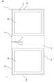
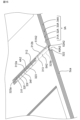
- FIG. 1 is a plan view of a configuration example of an antenna device according to a first embodiment
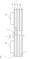
- FIG. The bottom view of the antenna device of FIG. Schematic side view of the antenna device of FIG. 2 is an exploded perspective view of the ground electrode of the antenna device of FIG. 1
- FIG. A is a partial plan view of a configuration example of a ground layer that is the top layer of the ground electrode
- B is a partial plan view of a configuration example of the ground layer that is the second layer of the ground electrode.
- A is a partial plan view of a configuration example of a ground layer that is the third layer of the ground electrode
- B is a partial plan view of a configuration example of the ground layer that is the lowest layer of the ground electrode. 4.
- FIG. 2 is a plan view of a configuration example of an antenna device according to a second embodiment; Partially enlarged perspective view of the antenna device of FIG. 13 Another partial enlarged perspective view of the antenna device of FIG.
- FIG. 10 is a plan view of a configuration example of an antenna device according to a third embodiment
- FIG. 18 is a partially enlarged perspective view of the antenna device of FIG. 18 Another partial enlarged perspective view of the antenna device of FIG. 18
- FIG. 11 is a partial plan view of a configuration example of an antenna device according to a fourth embodiment
- FIG. 11 is a partial plan view of a configuration example of an antenna device according to a fifth embodiment
- FIG. 11 is a partial plan view of a configuration example of an antenna device according to a sixth embodiment;
- prefixes such as “first” and “second” are added to the component names when it is necessary to distinguish between multiple components. prefixes such as “first”, “second”, etc. may be omitted for the sake of readability.
- FIG. 1 is a plan view of a configuration example of an antenna device 1 according to a first embodiment.
- FIG. 2 is a bottom view of the antenna device 1.
- FIG. FIG. 3 is a schematic side view of the antenna device 1.
- FIG. In FIG. 3, the dimensional ratios of the components of the antenna device 1 are different from those in FIGS. 1 and 2 in order to make the configuration of the antenna device 1 easier to understand.
- the antenna device 1 is mounted on equipment for communication in a predetermined frequency band.
- the antenna device 1 of FIG. 1 includes a first antenna element 2a, a second antenna element 2b, and a substrate 7 on which the first antenna element 2a and the second antenna element 2b are mounted.
- each of the first antenna element 2a and the second antenna element 2b is a planar antenna (eg, patch antenna).
- Each of the first antenna element 2a and the second antenna element 2b is configured to correspond to a first frequency band and a second frequency band higher than the first frequency band.
- the first frequency band and the second frequency band are, for example, frequency bands used for wireless communication by UWB.
- the center frequency of the first frequency band is 6.5 GHz and the center frequency of the second frequency band is 8.0 GHz. Since each of the first antenna element 2a and the second antenna element 2b may be a conventionally well-known planar antenna, detailed description thereof will be omitted.
- the substrate 7 has a rectangular plate shape.
- the first antenna element 2 a and the second antenna element 2 b are arranged on one surface of the substrate 7 along the length direction of the substrate 7 .
- the substrate 7 includes a ground electrode 3 and a dielectric layer 6.
- the substrate 7 is constructed using a multilayer substrate.
- multilayer substrates include low-temperature co-fired ceramics (LTCC) multilayer substrates, multilayer resin substrates formed by laminating multiple resin layers composed of resins such as epoxy and polyimide, and liquid crystal polymers ( A multilayer resin substrate formed by laminating a plurality of resin layers composed of LCP), a multilayer resin substrate formed by laminating a plurality of resin layers composed of a fluororesin, and a ceramic multilayer substrate other than LTCC mentioned.
- LTCC low-temperature co-fired ceramics
- the ground electrode 3 is used as a ground for the first antenna element 2a and the second antenna element 2b. As shown in FIG. 3, the ground electrode 3 is on the rear side of the first antenna element 2a and the second antenna element 2b. A ground electrode 3 is coupled to the first antenna element 2a and the second antenna element 2b. As shown in FIGS. 1 and 2, the ground electrode 3 is rectangular. The ground electrode 3 has a length direction (horizontal direction in FIGS. 1 and 2), a width direction (vertical direction in FIGS. 1 and 2), and a thickness direction (vertical direction in FIG. 3). The ground electrode 3 has a first side 3a, a second side 3b, a third side 3c, and a fourth side 3d.
- the first side 3 a and the third side 3 c are opposed to each other and extend along the length direction of the ground electrode 3 .
- the second side 3 b and the second side 3 d face each other and extend along the width direction of the ground electrode 3 .
- the ground electrode 3 has a size that comprehensively covers the first antenna element 2a and the second antenna element 2b.
- the ground electrode 3 has a multilayer structure.
- the ground electrode 3 will be described in more detail below with reference to FIGS. 3 and 5 to 7.
- FIG. 3
- FIG. 4 is an exploded perspective view of the ground electrode 3.
- the ground electrode 3 includes multiple ground layers 31-34.
- the multiple ground layers 31 to 34 are arranged in the thickness direction of the ground electrode 3 . Spaces between the plurality of ground layers 31-34 are defined by the dielectric layer 6.
- the ground layer 31 is closest to the first antenna element 2a and the second antenna element 2b among the plurality of ground layers 31-34.
- the ground layer 31 is the top layer of the substrate 7 .
- a ground layer 31 defines the front surface of the substrate 7 .
- the ground layer 31 has a rectangular shape.
- the ground layer 31 has first to fourth sides 310a to 310d corresponding to the first to fourth sides 3a to 3d of the ground electrode 3, respectively.
- the ground layer 31 has slits 31a.
- the slit 31a is located in the central portion 31b of the ground layer 31 in the longitudinal direction.
- the ground layer 31 has a first opening 31c and a second opening 31d at both ends in the length direction of the ground layer 31, respectively.
- the first aperture 31c is larger than the first antenna element 2a.
- the second aperture 31d is larger than the second antenna element 2b.
- the ground layer 32 is the next closest to the first antenna element 2a and the second antenna element 2b after the ground layer 31 among the plurality of ground layers 31-34.
- the ground layer 32 is an intermediate layer (second layer) of the substrate 7 .
- the ground layer 32 is rectangular like the ground layer 31 .
- the ground layer 32 has first to fourth sides 320a to 320d corresponding to the first to fourth sides 3a to 3d of the ground electrode 3, respectively.
- the ground layer 32 has slits 32a.
- the slit 32a is located in the central portion 32b of the ground layer 32 in the longitudinal direction.
- the ground layer 32 has a first opening 32c and a second opening 32d at both ends in the length direction of the ground layer 32, respectively.
- the first aperture 32c is larger than the first antenna element 2a.
- the second aperture 32d is larger than the second antenna element 2b.
- the size of the first opening 32c of the ground layer 32 is equal to the size of the first opening 31c of the ground layer 31.
- the size of the second opening 32d of the ground layer 32 is equal to the size of the second opening 31d of the ground layer 31.
- the ground layer 33 is the next closest to the first antenna element 2a and the second antenna element 2b after the ground layer 32 among the plurality of ground layers 31-34.
- the ground layer 33 is an intermediate layer (third layer) of the substrate 7 .
- the ground layer 33 has a rectangular shape similar to the ground layers 31 and 32 .
- the ground layer 33 has first to fourth sides 330a to 330d corresponding to the first to fourth sides 3a to 3d of the ground electrode 3, respectively.
- the ground layer 33 has slits 33a.
- the slit 33a is located in the central portion 33b of the ground layer 33 in the longitudinal direction.
- the ground layer 33 has a first opening 33c and a second opening 33d at both ends in the length direction of the ground layer 33, respectively.
- the first aperture 33c is larger than the first antenna element 2a.
- the second aperture 33d is larger than the second antenna element 2b.
- the size of the first opening 33c of the ground layer 33 is equal to the size of the first opening 31c of the ground layer 31.
- the size of the second opening 33 d of the ground layer 33 is equal to the size of the second opening 31 d of the ground layer 31 .
- the ground layer 34 is the farthest from the first antenna element 2a and the second antenna element 2b among the plurality of ground layers 31-34.
- the ground layer 34 is the bottom layer of the substrate 7 .
- Ground layer 34 defines the rear surface of substrate 7 .
- the ground layer 34 has a rectangular shape similar to the ground layers 31-33.
- the ground layer 34 has first to fourth sides 340a to 340d corresponding to the first to fourth sides 3a to 3d of the ground electrode 3, respectively.
- the ground layer 34 has slits 34a.
- the slit 34a is located in the center portion 34b of the ground layer 34 in the longitudinal direction.
- the ground layer 34 does not have openings at both ends in the length direction of the ground layer 34 . Both ends of the ground layer 34 in the length direction face the rear surfaces of the first antenna element 2a and the second antenna element 2b, respectively.
- ground layers 31-34 are coupled to the first antenna element 2a and the second antenna element 2b.
- ground layers 31 to 34 are electrically coupled to each other by interlayer wiring formed in dielectric layer 6 .
- First antenna element 2a is located in first openings 31c-33c of ground layers 31-33 and is electrically coupled to ground layer 34 by interlayer wiring formed in dielectric layer 6.
- Second antenna element 2b is located in second openings 31d-33d of ground layers 31-33 and is electrically coupled to ground layer 34 by interlayer wiring formed in dielectric layer 6.
- the ground electrode 3 can function as a ground for the first antenna element 2a and the second antenna element 2b.
- the ground layers 31-34 have slits 31a-34a, respectively.
- the slits 31a-34a of the ground layers 31-34 will be further described below with reference to FIGS. 5-9. 5 to 9, the illustration of the dielectric layer 6 is omitted in consideration of the visibility of the drawings.
- FIG. 5A is a partial plan view of a configuration example of the ground layer 31, showing the vicinity of the slit 31a of the ground layer 31.
- FIG. The slit 31 a is located between the first antenna element 2 a and the second antenna element 2 b when viewed from the thickness direction of the ground electrode 3 .
- the slit 31a extends in a second direction that intersects the first direction (horizontal direction in FIG. 5A) connecting the first side 310a of the ground layer 31 to the first antenna element 2a and the second antenna element 2b. (vertical direction in FIG. 5A).
- the first side 310a is a side of the ground layer 31 corresponding to a predetermined side of the ground electrode 3 (the first side 3a in the present embodiment).
- the line connecting the first antenna element 2a and the second antenna element 2b is, for example, the line connecting the center of the first antenna element 2a and the center of the second antenna element 2b.
- the first direction corresponds to the length direction of the ground electrode 3 and the second direction corresponds to the width direction of the ground electrode 3 .
- the slit 31a in FIG. 5A has an open end 311, a side 312 on the first antenna element 2a side (left side in FIG. 5A), a side 313 on the second antenna element 2b side (right side in FIG. 5A), and a closed end. 314.
- the slit 31a is linear.
- the width of the slit 31a is not uniform, and has a portion with a narrow width and a portion with a wide width. More specifically, in the slit 31a, the side 313 on the side of the second antenna element 2b is linear, but the side 312 on the side of the first antenna element 2a is not linear, and the side 313 on the side of the second antenna element 2b is not linear. It is a shape in which the distance between is changed.
- Side 312 includes first and second portions 312 a and 312 b that are different in distance from side 313 .
- the second portion 312b is closer to the side 313 than the first portion 312a.
- the second portion 312b is an end portion of the first piece 51 on the side 313 side that protrudes to the side 313 from the first portion 312a in the ground layer 31 .
- the first piece 51 is rectangular.
- the width of the slit 31a is narrower at the second portion 312b than at the first portion 312a.
- the second portion 312b is closer to the open end 311 of the slit 31a than the first portion 312a.
- the second portion 312b is closer to the open end 311 of the slit 31a than the center of the slit 31a. In this embodiment, the second portion 312b is at the open end 311 of the slit 31a.
- FIG. 5B is a partial plan view of a configuration example of the ground layer 32, showing the vicinity of the slit 32a of the ground layer 32.
- the slit 32 a is located between the first antenna element 2 a and the second antenna element 2 b when viewed from the thickness direction of the ground electrode 3 .
- the slit 32a extends from the first side 320a of the ground layer 32 in the second direction (vertical direction in FIG. 5B).
- the first side 320 a is a side of the ground layer 32 corresponding to a predetermined side of the ground electrode 3 (first side 3 a in the present embodiment).
- the slit 32a in FIG. 5B includes an open end 321, a side 322 on the first antenna element 2a side (left side in FIG. 5B), a side 323 on the second antenna element 2b side (right side in FIG. 5B), and a closed end. 324.
- the slit 32a is linear.
- the width of the slit 32a is not uniform, and has a portion with a narrow width and a portion with a wide width. More specifically, in the slit 32a, the side 322 on the side of the first antenna element 2a is linear, but the side 323 on the side of the second antenna element 2b is not linear, and the distance from the side 322 changes. Shape.
- Side 323 includes third and fourth portions 323 a and 323 b that are different in distance from side 322 .
- the fourth portion 323b is closer to the side 322 than the third portion 323a.
- the fourth portion 323b is an end portion on the side 322 side of the second piece 52 that protrudes to the side 322 from the third portion 323a in the ground layer 32 .
- the second piece 52 is rectangular.
- the fourth portion 323b is closer to the open end 321 of the slit 32a than the third portion 323a.
- the fourth portion 323b is closer to the open end 321 of the slit 32a than the center of the slit 32a. In this embodiment, the fourth portion 323b is at the open end 321 of the slit 32a.
- FIG. 6A is a partial plan view of a configuration example of the ground layer 33, showing the vicinity of the slit 33a of the ground layer 33.
- FIG. The slit 33 a is located between the first antenna element 2 a and the second antenna element 2 b when viewed from the thickness direction of the ground electrode 3 .
- the slit 33a extends from the first side 330a of the ground layer 33 in the second direction (vertical direction in FIG. 6A).
- the first side 330a is a side of the ground layer 33 corresponding to a predetermined side of the ground electrode 3 (the first side 3a in the present embodiment).
- the 6A includes an open end 331, a side 332 on the first antenna element 2a side (left side in FIG. 6A), a side 333 on the second antenna element 2b side (right side in FIG. 6A), and a closed end. 334.
- the slit 33a is linear. The width of the slit 33a is uniform.
- FIG. 6B is a partial plan view of a configuration example of the ground layer 34, showing the vicinity of the slit 34a of the ground layer 34.
- the slit 34 a is located between the first antenna element 2 a and the second antenna element 2 b when viewed from the thickness direction of the ground electrode 3 .
- the slit 34a extends from the first side 340a of the ground layer 34 in the second direction (vertical direction in FIG. 6B).
- the first side 340a is a side corresponding to a predetermined side (first side 3a in the present embodiment) of the ground electrode 3 in the ground layer 34 .
- the 6B includes an open end 341, a side 342 on the side of the first antenna element 2a (left side in FIG. 6B), a side 343 on the side of the second antenna element 2b (right side in FIG. 6B), and a closed end. 344.
- the slit 34a is linear. The width of the slit 34a is uniform.
- FIG. 7A is a partial plan view of a configuration example of the ground electrode 3, showing the vicinity of the slits 31a to 34a.
- FIG. 7B is a partial bottom view of a configuration example of the ground electrode 3, showing the vicinity of the slits 31a to 34a.
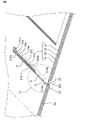
- FIG. 8 is a partially enlarged perspective view of the ground electrode 3, showing the vicinity of the slits 31a to 34a.
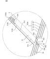
- 9 is an enlarged view of the portion indicated by P1 in FIG. 8.
- FIG. 8 is a partially enlarged perspective view of the ground electrode 3, showing the vicinity of the slits 31a to 34a.
- the slits 31a-34a of the ground layers 31-34 are arranged in the thickness direction of the ground electrode 3.
- FIG. 8 and 9 the slits 31a-34a of the ground layers 31-34 are arranged in the thickness direction of the ground electrode 3.
- the open ends 311 to 341 of the slits 31a to 34a coincide with each other in the thickness direction of the ground electrode 3 .
- the closed ends 314 to 344 of the slits 31a to 34a coincide with each other in the thickness direction of the ground electrode 3 .
- the lengths of the slits 31a-34a are equal to each other.
- the length of the slits 31a-34a is, for example, the distance between the open ends 311-341 and the closed ends 314-344 of the slits 31a-34a.
- each of the slits 31a-34a has a length based on the wavelength corresponding to the first frequency band.
- the first portion 312a is aligned with the third portion 323a in the first direction and is closer to the first antenna element 2a than the third portion 323a.
- the second portion 312b is aligned with the fourth portion 323b in the first direction, closer to the second side 313 than the first portion 312a, and closer to the second antenna element 2b than the fourth portion 323b.
- the third portion 323a is aligned with the first portion 312a in the first direction and is closer to the second antenna element 2b than the first portion 312a.
- the fourth portion 323b is aligned with the second portion 323b in the first direction, closer to the third side 322 than the third portion 323a, and closer to the first antenna element 2a than the second portion 312b.
- the space between the first portion 312a of the slit 31a of the ground layer 31 and the side 313 and the space between the third portion 323a of the slit 32a of the ground layer 32 and the side 322 are formed. are opposed to each other in the thickness direction of the ground electrode 3 , and thus form a space penetrating the ground layers 31 and 32 .
- the space between the second portion 312b of the slit 31a of the ground layer 31 and the side 313 and the space between the fourth portion 323a of the slit 32a of the ground layer 32 and the side 322 are equal to the thickness of the ground electrode 3.
- the first piece 51 of the ground layer 31 and the second piece 52 of the ground layer 32 overlap each other with a predetermined gap in the thickness direction of the ground electrode 3 .
- the first portion 312a of the side 312 of the slit 31a on the side of the first antenna element 2a coincides with the side 322 of the slit 32a on the side of the first antenna element 2a in the thickness direction of the ground electrode 3.
- the third portion 323a of the side 323 of the slit 32a on the second antenna element 2b side coincides with the side 313 of the slit 31a on the second antenna element 2b side in the thickness direction of the ground electrode 3 .
- the side 332 of the slit 33a on the side of the first antenna element 2a is the first portion 312a of the side 312 of the slit 31a on the side of the first antenna element 2a and the first portion 312a of the slit 32 in the thickness direction of the ground electrode 3. It coincides with the side 322 on the side of the antenna element 2a.
- a side 333 of the slit 33a on the side of the second antenna element 2b is, in the thickness direction of the ground electrode 3, a third portion 323a of the side 323 of the slit 32a on the side of the second antenna element 2b and a side of the slit 31a on the side of the second antenna element 2b. Matches side 313 .
- the side 342 of the slit 34a on the side of the first antenna element 2a is, in the thickness direction of the ground electrode 3, the first portion 312a of the side 312 of the slit 31a on the side of the first antenna element 2a and the first portion 312a of the slit 32a. It coincides with the side 322 on the side of the antenna element 2a.
- a side 343 of the slit 34a on the side of the second antenna element 2b is, in the thickness direction of the ground electrode 3, a third portion 323a of the side 323 of the slit 32a on the side of the second antenna element 2b and a side of the slit 31a on the side of the second antenna element 2b. Matches side 313 .
- the slit structure 4 includes an open end 40, a side 41 on the side of the first antenna element 2a, and a side 42 on the side of the second antenna element 2b.
- the open end 40 is defined by the open end 311 of the slit 31 a of the ground layer 31 .
- the side 41 on the side of the first antenna element 2a is defined by the side 322 of the ground layer 32 on the side of the first antenna element 2a.
- the side 42 on the side of the first antenna element 2a is defined by the side 313 of the ground layer 31 on the side of the second antenna element 2b.
- the shape of the slit structure 4 matches the shape of the slits 33a, 34a of the ground layers 33, 34 in the plane orthogonal to the thickness direction of the ground electrode 3.
- the slit structure 4 is defined by slits 31a-34a.
- the slits 31a-34a are located in the central portions 31b-34b of the ground layers 31-34.
- Central portions 31b to 34b of the ground layers 31 to 34 are portions of the ground electrode 3 between the first antenna element 2a and the second antenna element 2b.
- a slit structure 4 is between the first antenna element 2a and the second antenna element 2b.
- the ground layer 31 has a first piece 51.
- the first piece 51 extends from the side 322 of the ground layer 32 on the side of the first antenna element 2a toward the side of the second antenna element 2b in a plane perpendicular to the thickness direction of the ground electrode 3 .
- Ground layer 32 has a second piece 52 .
- the second piece 52 extends from the side 313 of the ground layer 31 on the side of the second antenna element 2b to the side of the first antenna element 2a in the plane orthogonal to the thickness direction of the ground electrode 3 .
- the first piece 51 of the ground layer 31 and the second piece 52 of the ground layer 32 overlap each other with a predetermined gap in the thickness direction of the ground electrode 3 .
- the first piece 51 and the second piece 52 constitute the opposing structure 5 .
- the facing structure 5 is positioned within the slit structure 4 in the plane perpendicular to the thickness direction of the ground electrode 3 .
- the facing structure 5 includes one pair of a first piece 51 and a second piece 52 .
- the second portion 312b is closer to the open end 311 of the slit 31a than the center of the slit 31a
- the fourth portion 323b is closer to the open end 321 of the slit 32a than the center of the slit 32a. Therefore, the first piece 51 and the second piece 52 are closer to the open end 40 of the slit structure 4 than the center of the slit structure 4 .
- the second portion 312b is located at the open end 311 of the slit 31a, and the fourth portion 323b is located at the open end 321 of the slit 32a.
- the first piece 51 and the second piece 52 are at the open end 40 of the slit structure 4 .
- the lengths of the first piece 51 and the second piece 52 are equal.
- the length of the first piece 51 and the second piece 52 is less than half the length of the slit structure 4 .
- the area of the overlapping portion of the first piece 51 and the second piece 52 in the opposing structure 5 is set to 1/2 or less of the area of the slit structure 4 when viewed from the thickness direction of the ground electrode 3 . That is, when viewed from the thickness direction of the ground electrode 3, the area of the portion between the second portion 312b of the slit 31a and the fourth portion 323b of the slit 32a in the ground electrode 3 is the second antenna of the slit 31a in the ground electrode 3.
- the area between the side 313 on the side of the element 2b and the side 322 of the slit 32a on the side of the first antenna element 2a is 1/2 or less.
- the slit structure 4 and the facing structure 5 shown in FIGS. 1 to 3 are formed by the ground layers 31 to 34 having slits 31a to 34a, respectively.
- the ground electrode 3 includes the slit structure 4 and the facing structure 5 inside the slit structure 4 .
- the facing structure 5 includes a first piece 51 extending from a first side 41 of the slit structure 4 on the side of the first antenna element 2a to the side of the second antenna element 2b, and a second side 42 of the slit structure 4 on the side of the second antenna element 2b. and a second piece 52 extending from the first antenna element 2a side and overlapping the first piece 51 .
- the first piece 51 and the second piece 52 of the facing structure 5 can be capacitively coupled within the slit structure 4 .
- the slit structure 4 is provided for improving the isolation between the first antenna element 2a and the second antenna element 2b.
- the length of the slit structure 4 is determined in consideration of the improvement of isolation between the first antenna element 2a and the second antenna element 2b.
- the slit structure 4 has a length based on the wavelength corresponding to the first frequency band.
- the length of the slit structure 4 is set based on the electrical length of 1/4 wavelength corresponding to the first frequency band.
- the facing structure 5 is inside the slit structure 4 . In the antenna device 1 , the area through which radio waves can pass can be narrowed in the slit structure 4 compared to the case where the facing structure 5 is not provided in the slit structure 4 .
- the facing structure 5 functions as a capacitor having capacitance, and the first piece 51 and the second piece 52 of the facing structure 5 face each other in the thickness direction of the ground electrode 3 which is the thickness direction of the slit structure 4 . Therefore, in the antenna device 1, even if the length of the slit structure 4 is shortened, compared with the case where the facing structure 5 is not provided in the slit structure 4, the electrical length of 1/4 of the wavelength corresponding to the first frequency band is maintained. can be maintained. That is, in the antenna device 1, since the facing structure 5 is provided within the slit structure 4, the length of the slit structure 4 itself is shorter than 1/4 of the wavelength corresponding to the first frequency band.
- the antenna device 1 of the present embodiment can reduce the leakage of radio waves to the rear surface side of the antenna elements while improving the isolation between the antenna elements.
- the antenna device 1 of the present embodiment radiates radio waves in a first frequency band (frequency band around 6.5 GHz) and a second frequency band (frequency band around 8.0 GHz).
- the slit structure 4 of the ground electrode 3 has a length based on the wavelength corresponding to the first frequency band for improved isolation between the first antenna element 2a and the second antenna element 2b in the first frequency band. .
- the isolation was measured. Isolation measurements were performed for the antenna device 1 of the present embodiment and the antenna devices of Comparative Examples 1 and 2.
- the antenna substrate of Comparative Example 1 is the same as the antenna device 1 except that the slit structure 4 is not provided.
- the antenna substrate of Comparative Example 2 is the same as the antenna device 1 except that the opposing structure 5 is not provided and the length of the slit structure 4 is equal to 1/4 of the wavelength corresponding to the first frequency band.
- FIG. 10 is a graph of measurement results of the isolation of the antenna device of Comparative Example 1.
- FIG. 11 is a graph of measurement results of isolation of the antenna device of Comparative Example 2.
- FIG. FIG. 12 is a graph of isolation measurement results of the antenna device 1 according to the first embodiment. Specifically, FIGS. 10 to 12 are graphs showing frequency on the horizontal axis and isolation on the vertical axis. be. The range of frequencies in which the isolation was measured is 6.0 GHz to 7.0 GHz.
- the isolation near 6.5 GHz is 19.4 dB.
- the isolation near 6.5 GHz is 20.2 dB.
- the isolation near 6.5 GHz is 21.9 dB.
- the first antenna element 2a near 6.5 GHz corresponding to the first frequency band is higher than the case where only the slit structure 4 is formed on the ground electrode 3. and the isolation between the second antenna elements 2b can be improved.
- peak efficiency and peak gain were measured for the antenna device 1 of the present embodiment and the antenna devices of Comparative Examples 1 and 2. Peak efficiency and peak gain measurements were performed for a peak near 6.5 GHz corresponding to the first frequency band and a peak near 8.0 GHz corresponding to the second frequency band. As a result of measuring the peak efficiency, it was confirmed that the antenna device 1 of the present embodiment and the antenna device of Comparative Example 2 had improved peak efficiency, particularly at a peak near 6.5 GHz, compared to the antenna device of Comparative Example 1. did it. This is because the antenna device 1 of the present embodiment and the antenna device of the comparative example 2 can improve the isolation near 6.5 GHz.
- Comparative Example 2 exhibited worse peak gain than Comparative Example 1 at a peak near 8.0 GHz. This is considered to be due to the influence of leakage of radio waves of the second frequency band from the slit structure 4 .
- the antenna device 1 of the present embodiment had a peak gain comparable to that of the comparative example 1 at a peak near 8.0 GHz. It is considered that this is because the facing structure 5 is present in the slit structure 4 and the length of the slit structure 4 itself is shorter than that of the second comparative example. That is, the antenna device 1 of the present embodiment can improve the isolation near 6.5 GHz as in Comparative Example 2, and further improve the peak gain at the peak near 8.0 GHz compared to Comparative Example 2. can be achieved.
- the antenna device 1 includes the first antenna element 2a and the second antenna element 2b, and the first antenna element 2a and the second antenna element 2b on the rear side of the first antenna element 2a and the second antenna element 2b. a ground electrode 3 coupled to 2b.
- the ground electrode 3 includes first and second ground layers (ground layers 31 and 32) arranged in the thickness direction of the ground electrode 3 .
- the first ground layer (ground layer 31) is located between the first antenna element 2a and the second antenna element 2b when viewed from the thickness direction of the ground electrode 3, and the first ground layer (ground layer 31) has a predetermined thickness of the ground electrode 3.
- the second ground layer extends in the second direction from the side 320a corresponding to the predetermined side 3a of the ground electrode 3 in the second ground layer (ground layer 32), and extends in the second direction in the thickness direction of the ground electrode 3.
- slit 31a Along with the slit (slit 31a), it has a second slit (slit 32a) including a third side 322 on the side of the first antenna element 2a and a fourth side 323 on the side of the second antenna element 2b.
- a first side 312 of the first slit (slit 31a) includes a first portion 312a and a second portion 312b closer to the second side 313 than the first portion 312a.
- a fourth side 323 of the second slit (slit 32a) includes a third portion 323a that is aligned with the first portion 312a in the first direction and is closer to the second antenna element 2b than the first portion 312a, and a second slit 32a in the first direction.
- It includes a portion 323b and a fourth portion 323b which is closer to the third side 322 than the third portion 323a and closer to the first antenna element 2a than the second portion 312b.
- This configuration makes it possible to reduce radio wave leakage to the rear side of the first and second antenna elements 2a and 2b while improving the isolation between the first and second antenna elements 2a and 2b.
- the first portion 312a of the first side 312 of the first slit (slit 31a) coincides with the third side 322 of the second slit (slit 32a) in the thickness direction of the ground electrode 3.
- a third portion 323 a of the fourth side 323 of the second slit (slit 32 a ) matches the second side 313 of the first slit (slit 31 a ) in the thickness direction of the ground electrode 3 .
- This configuration can compactly configure the first slit (slit 31a) and the second slit (slit 32a).
- the ground electrode 3 includes first and second ground layers (ground layers 31 and 32 ) and third ground layers (ground layers 33 and 34 ) arranged in the thickness direction of the ground electrode 3 .
- the third ground layer (ground layers 33, 34) extends in the second direction from sides 330a, 340a corresponding to predetermined sides of the ground electrode 3 in the third ground layer (ground layers 33, 34). It has third slits (slits 33a, 34a) aligned with the first and second slits (slits 31a, 32a) in the thickness direction.
- This configuration increases the number of ground layers and improves the isolation between the first and second antenna elements (antenna elements 2a and 2b). ) to reduce the leakage of radio waves to the rear surface side.
- the third slits include fifth sides 332, 342 on the side of the first antenna element 2a and sixth sides 333, 343 on the side of the second antenna element 2b.
- the fifth sides 332 and 342 of the third slits (slits 33a and 34a) correspond to the first part 312a and the second slit (slit 32a) of the first side 312 of the first slit (slit 31a) in the thickness direction of the ground electrode 3. ) matches the third side 322 of .
- the sixth sides 333 and 343 of the third slits are aligned with the third part 323a of the fourth side 323 of the second slit (slit 32a) and the first slit (slit 31a) in the thickness direction of the ground electrode 3. ) coincides with the second side 312 of .
- This configuration can compactly configure the third slits (slits 33a and 34a).
- the first ground layer (ground layer 31) and the second ground layer (ground layer 32) are adjacent to each other. This configuration can further reduce radio wave leakage to the rear side of the antenna elements 2a and 2b.
- the first ground layer (ground layer 31) is closest to the first antenna element 2a and the second antenna element 2b among the first to third ground layers (ground layers 31 to 34).
- the second ground layer includes the first antenna element 2a and the second antenna element 2b next to the first ground layer (ground layer 31) among the first to third ground layers (ground layers 31 to 34). close to This configuration can further reduce radio wave leakage to the rear side of the first and second antenna elements 2a and 2b.
- the second portion 312b is closer to the open end 311 of the first slit (slit 31a) than the first portion 312a.
- the fourth portion 323b is closer to the open end 321 of the second slit (slit 32a) than the third portion 323a. This configuration can further reduce radio wave leakage to the rear side of the first and second antenna elements 2a and 2b.
- the second portion 312b is closer to the open end 311 of the first slit (slit 31a) than the center of the first slit (slit 31a).
- the fourth portion 323b is closer to the open end 321 of the second slit (slit 32a) than the center of the second slit (slit 32a). This configuration can further reduce radio wave leakage to the rear side of the first and second antenna elements 2a and 2b.
- the second portion 312b is located at the open end 311 of the first slit (slit 31a).
- the fourth portion 323b is located at the open end 321 of the second slit (slit 32a). This configuration can further reduce radio wave leakage to the rear side of the first and second antenna elements 2a and 2b.
- the set of the first slit (slit 31a) and the second slit (slit 32a) includes one set of the second part 312b and the fourth part 323b. This configuration can further reduce radio wave leakage to the rear side of the first and second antenna elements 2a and 2b.
- the antenna device 1 when viewed from the thickness direction of the ground electrode 3, the second portion 312b of the first side 312 of the first slit (slit 31a) in the ground electrode 3 and the fourth side 323 of the second slit (slit 32a)
- the area of the portion between the fourth portion 323b is the area of the portion between the second side 313 of the first slit (slit 31a) and the third side 322 of the second slit (slit 32a) in the ground electrode 3. 1/2 or less.
- This configuration can further reduce radio wave leakage to the rear side of the first and second antenna elements 2a and 2b.
- each of the first antenna element 2a and the second antenna element 2b is configured to support a first frequency band and a second frequency band higher than the first frequency band.
- Each of the first slit (slit 31a) and the second slit (slit 32a) has a length based on the wavelength corresponding to the first frequency band. This configuration improves the isolation between the first and second antenna elements 2a, 2b in the first frequency band, while at the same time providing the rear side of the first and second antenna elements 2a, 2b in the second frequency band. radio wave leakage can be reduced.
- each of the first antenna element 2a and the second antenna element 2b is a planar antenna. This configuration enables the size reduction of the antenna device 1 .
- FIG. 13 is a plan view of a configuration example of the antenna device 1A according to the second embodiment.
- An antenna device 1A of FIG. 13 includes a first antenna element 2a, a second antenna element 2b, and a substrate 7A on which the first antenna element 2a and the second antenna element 2b are mounted.
- the substrate 7A includes a ground electrode 3A and a dielectric layer 6A.
- the substrate 7A is configured using a multilayer substrate.
- the ground electrode 3A of FIG. 13 has a plurality of slit structures (a first slit structure 4A1 and a second slit structure 4A2) and a plurality of facing structures (a first facing structure 5A1 and a second facing structure 5A2). is different from the ground electrode 3 of .
- FIG. 14 is a partially enlarged perspective view of the antenna device 1A. More specifically, FIG. 14 is an enlarged perspective view of the vicinity of the first slit structure 4A1 in the antenna device 1A.
- FIG. 15 is another partially enlarged perspective view of the antenna device 1A. More specifically, FIG. 15 is an enlarged perspective view of the vicinity of the second slit structure 4A2 in the antenna device 1A.
- the ground electrode 3A has a rectangular shape.
- the ground electrode 3A has a first side 3aa, a second side 3ba, a third side 3ca, and a fourth side 3da.
- the first side 3aa and the third side 3ca are opposed to each other and extend along the length direction of the ground electrode 3A.
- the second side 3ba and the fourth side 3da face each other and extend along the width direction of the ground electrode 3A.
- the ground electrode 3A includes multiple ground layers 31A-34A.
- the ground layers 31A-34A differ from the ground layers 31-34 of the first embodiment in that they have two sets of slits 31e-34e and 31f-34f.
- the ground electrode 3A includes a first slit structure 4A1, a second slit structure 4A2, a first facing structure 5A1, and a second facing structure 5A2.
- a set of slits 31e to 34e defines a first slit structure 4A1 and a first opposing structure 5A1.
- the slits 31e-34e have the same shape as the slits 31a-34a.
- the first portion 312a is aligned with the third portion 323a in the first direction and is closer to the first antenna element 2a than the third portion 323a.
- the second portion 312b is aligned with the fourth portion 323b in the first direction, closer to the second side 313 than the first portion 312a, and closer to the second antenna element 2b than the fourth portion 323b.
- each of the slits 31e-34e has a length based on the wavelength corresponding to the first frequency band.
- the first slit structure 4A1 extends inside the ground electrode 3A from the first side 3aa of the ground electrode 3A and has an open end 40A1.
- the first slit structure 4A1 is located between the first antenna element 2a and the second antenna element 2b, and separates the first side 41A1 on the side of the first antenna element 2a and the second side 42A1 on the side of the second antenna element 2b. have.
- the side 41A1 on the side of the first antenna element 2a is defined by the side 322 of the ground layer 32A on the side of the first antenna element 2a.
- the side 42A1 on the side of the first antenna element 2a is defined by the side 313 of the ground layer 31 on the side of the second antenna element 2b.
- the ground layer 31A has a first piece 51A1.
- the first piece 51A1 extends from the side 322 of the ground layer 32A on the side of the first antenna element 2a to the side of the second antenna element 2b in a plane perpendicular to the thickness direction of the ground electrode 3A.
- the ground layer 32A has a second piece 52A1.
- the second piece 52A1 extends from the side 313 of the ground layer 31A on the side of the second antenna element 2b toward the first antenna element 2a in a plane perpendicular to the thickness direction of the ground electrode 3A.
- the first piece 51A1 of the ground layer 31A and the second piece 52A1 of the ground layer 32A overlap each other with a predetermined gap in the thickness direction of the ground electrode 3A.
- the first piece 51A1 and the second piece 52A1 constitute the first opposing structure 5A1.
- the first facing structure 5A1 is positioned within the first slit structure 4A1 in the plane orthogonal to the thickness direction of the ground electrode 3A.
- the first facing structure 5A1 includes one set of a first piece 51A1 and a second piece 52A1.
- the first piece 51A1 and the second piece 52A1 are at the open end 40A1 of the first slit structure 4A1.
- the first piece 51A1 and the second piece 52A1 have the same length.
- the lengths of the first piece 51A1 and the second piece 52A1 are less than half the length of the first slit structure 4A1.
- the area of the overlapping portion of the first piece 51A1 and the second piece 52A1 in the first facing structure 5A1 is 1/2 or less of the area of the first slit structure 4A1.
- a set of slits 31f to 34f defines a second slit structure 4A2 and a second opposing structure 5A2.
- the slits 31f-34f have the same shape as the slits 31a-34a.
- the first portion 312a is aligned with the third portion 323a in the first direction and is closer to the first antenna element 2a than the third portion 323a.
- the second portion 312b is aligned with the fourth portion 323b in the first direction, closer to the second side 313 than the first portion 312a, and closer to the second antenna element 2b than the fourth portion 323b.
- each of the slits 31f-34f has a length based on the wavelength corresponding to the second frequency band.
- the second slit structure 4A2 extends inside the ground electrode 3A from the third side 3ca of the ground electrode 3A and has an open end 40A2.
- the second slit structure 4A2 is located between the first antenna element 2a and the second antenna element 2b, and separates the first side 41A2 on the side of the first antenna element 2a and the second side 42A2 on the side of the second antenna element 2b. have.
- the side 41A2 on the side of the first antenna element 2a is defined by the side 322 of the ground layer 32A on the side of the first antenna element 2a.
- the side 42A1 on the side of the first antenna element 2a is defined by the side 313 of the ground layer 31A on the side of the second antenna element 2b.
- the ground layer 31A has a first piece 51A2.
- the first piece 51A2 extends from the side 322 of the ground layer 32A on the side of the first antenna element 2a to the side of the second antenna element 2b in a plane perpendicular to the thickness direction of the ground electrode 3A.
- the ground layer 32A has a second piece 52A2.
- the second piece 52A2 extends from the side 313 of the ground layer 31A on the side of the second antenna element 2b toward the first antenna element 2a in a plane perpendicular to the thickness direction of the ground electrode 3A.
- the first piece 51A2 of the ground layer 31A and the second piece 52A2 of the ground layer 32A overlap each other with a predetermined gap in the thickness direction of the ground electrode 3A.
- the first piece 51A2 and the second piece 52A2 constitute the second facing structure 5A2.
- the second facing structure 5A2 is positioned within the second slit structure 4A2 in the plane perpendicular to the thickness direction of the ground electrode 3A.
- the second facing structure 5A2 includes one set of a first piece 51A2 and a second piece 52A2.
- the first piece 51A2 and the second piece 52A2 are at the open end 40A2 of the second slit structure 4A2.
- the first piece 51A2 and the second piece 52A2 have the same length.
- the lengths of the first piece 51A2 and the second piece 52A2 are less than half the length of the second slit structure 4A2.
- the overlapping area of the first piece 51A2 and the second piece 52A2 in the second facing structure 5A2 is less than or equal to half the area of the second slit structure 4A2.
- the first slit structure 4A1 and the second slit structure 4A2 is provided for improving isolation between the first antenna element 2a and the second antenna element 2b.
- the first slit structure 4A1 has a length based on the wavelength corresponding to the first frequency band. As an example, the length of the first slit structure 4A1 is set based on the electrical length of 1/4 of the wavelength corresponding to the first frequency band.
- the second slit structure 4A2 has a length based on the wavelength corresponding to the second frequency band. As an example, the length of the second slit structure 4A2 is set based on the electrical length of 1/4 of the wavelength corresponding to the second frequency band.
- first facing structure 5A1 inside the first slit structure 4A1.
- the area through which radio waves can pass can be narrowed in the first slit structure 4A1 compared to the case where the first opposing structure 5A1 is not provided in the first slit structure 4A1.
- the first facing structure 5A1 functions as a capacitor having capacitance, in the antenna device 1A, the length of the first slit structure 4A1 is reduced compared to the case where the first facing structure 5A1 does not exist within the first slit structure 4A1. Even if it is shortened, the electrical length of 1/4 of the wavelength corresponding to the first frequency band can be maintained. Therefore, it is possible to reduce the possibility that the radio waves from the first and second antenna elements 2a and 2b pass through the first slit structure 4A1 and reach the rear side of the first and second antenna elements 2a and 2b.
- the area through which radio waves can pass can be narrowed in the second slit structure 4A2 compared to the case where the second opposing structure 5A2 is not provided in the second slit structure 4A2. Furthermore, since the second facing structure 5A2 functions as a capacitor having capacitance, in the antenna device 1A, the length of the second slit structure 4A2 is reduced compared to the case where the second facing structure 5A2 does not exist within the second slit structure 4A2. Even if it is shortened, the electrical length of 1/4 of the wavelength corresponding to the second frequency band can be maintained. Therefore, it is possible to reduce the possibility that the radio waves from the first and second antenna elements 2a and 2b pass through the second slit structure 4A2 and reach the rear side of the first and second antenna elements 2a and 2b.
- the antenna device 1A of the present embodiment reduces the leakage of radio waves to the rear surface side of the antenna elements while improving the isolation between the antenna elements (the first and second antenna elements 2a and 2b). becomes possible.
- the antenna device 1A of the present embodiment radiates radio waves in a first frequency band (frequency band around 6.5 GHz) and a second frequency band (frequency band around 8.0 GHz).
- the first slit structure 4A1 of the ground electrode 3A has a length based on the wavelength corresponding to the first frequency band in order to improve isolation between the first antenna element 2a and the second antenna element 2b in the first frequency band.
- the second slit structure 4A2 of the ground electrode 3A has a length based on the wavelength corresponding to the second frequency band for improved isolation between the first antenna element 2a and the second antenna element 2b in the second frequency band.
- the isolation was measured. The isolation measurement was performed for the antenna device 1A of the present embodiment and the antenna device 1 of the first embodiment.
- FIG. 16 is a graph of isolation measurement results of the antenna device 1 according to the first embodiment.
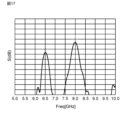
- FIG. 17 is a graph of isolation measurement results of the antenna device 1A according to the second embodiment.
- FIGS. 16 and 17 are graphs showing frequency on the horizontal axis and isolation on the vertical axis. be.
- the frequency range in which the isolation was measured is 5.0 GHz to 10.0 GHz.
- FIGS. 16 and 17 according to the antenna device 1, it was confirmed that isolation was improved near 6.5 GHz and near 8.0 GHz.
- the isolation near 6.5 GHz is 21.9 dB
- the isolation near 8.0 GHz is 17.9 dB
- the isolation near 6.5 GHz is 23.2 dB
- the isolation near 8.0 GHz is 19.2 dB.
- each of the first antenna element 2a and the second antenna element 2b is configured to support a first frequency band and a second frequency band higher than the first frequency band.
- the ground electrode 3A has a first set of first and second slits (slits 31e, 32e) and a second set of first and second slits (slits 31f, 32f).
- Each of the first and second slits (slits 31e, 32e) of the first set has a length based on the wavelength corresponding to the first frequency band.
- Each of the second set of first and second slits (slits 31f, 32f) has a length based on the wavelength corresponding to the second frequency band.
- FIG. 18 is a plan view of a configuration example of the antenna device 1B according to the third embodiment.
- An antenna device 1B in FIG. 18 includes a plurality of (three in FIG. 16) antenna elements 2c to 2e and a substrate 7B on which the plurality of antenna elements 2c to 2e are mounted.
- Each of the antenna elements 2c to 2e is a planar antenna (eg, patch antenna).
- Each of the antenna elements 2c-2e is configured to correspond to a first frequency band and a second frequency band higher than the first frequency band.
- the first frequency band and the second frequency band are, for example, frequency bands used for wireless communication by UWB.
- the center frequency of the first frequency band is 6.5 GHz and the center frequency of the second frequency band is 8.0 GHz.
- Each of the antenna elements 2c to 2e may be a conventionally well-known planar antenna, so detailed description thereof will be omitted.
- the substrate 7B is an L-shaped plate.
- the substrate 7B has a first portion 71B, a second portion 72B and a third portion 73B.
- the first portion 71B has a square shape.
- the first portion 71B includes first and second sides (left and right sides in FIG. 18) in a first direction (horizontal direction in FIG. 18) orthogonal to the thickness direction of the first portion 71B, and the thickness of the first portion 71B. It has a first side and a second side (upper side and lower side in FIG. 18) in a second direction (vertical direction in FIG. 18) orthogonal to the direction and the first direction.
- the second portion 72B protrudes from the second side (the right side in FIG. 18) of the first portion 71B in the first direction.
- the third portion 73B protrudes from the second side (lower side in FIG. 18) of the first portion 71B in the second direction.
- three antenna elements 2c, 2d and 2e are arranged on the first to third parts 71B, 72B and 73B, respectively.
- the two antenna elements 2c and 2d in the first portion 71B and the second portion 72B are arranged in the first direction (horizontal direction in FIG. 18) of the first portion 71B.
- the two antenna elements 2c and 2e in the first portion 71B and the third portion 73B are arranged in the second direction (vertical direction in FIG. 18) of the first portion 71B.
- the three antenna elements 2c to 2e are arranged on the substrate 7B so as to form an L shape when viewed from the thickness direction of the substrate 7B. According to this, it is possible to detect the reception angle (AoA) in each of the first direction and the second direction.
- the substrate 7B includes a ground electrode 3B and a dielectric layer 6B.
- the substrate 7B is constructed using a multilayer substrate.
- the ground electrode 3B is L-shaped like the substrate 7B.
- the ground electrode 3B has a first side 3ab, a second side 3bb, a third side 3cb, a fourth side 3db, a fifth side 3eb, and a sixth side 3fb.
- the first side 3ab is a side at the first end (upper end side in FIG. 18) in the second direction of the substrate 7B and corresponds to the first portion 71B and the second portion 72B.
- the second side 3bb is a side on the first end side (the left end side in FIG. 18) in the second direction of the substrate 7B and corresponds to the first portion 71B and the third portion 73B.
- the third side 3cb is a side at the second end (lower end side in FIG. 18) of the substrate 7B in the second direction and corresponds to the third portion 73B.
- the fourth side 3db is a side on the second end side (the right end side in FIG. 18) in the first direction of the substrate 7B and corresponds to the third portion 73B.
- the fifth side 3eb is a side of the second end (lower end side in FIG. 18) of the substrate 7B in the second direction and corresponds to the second portion 72B.
- the sixth side 3fb is a side on the second end side (the right end side in FIG. 18) in the first direction of the substrate 7B and corresponds to the second portion 72B.
- the ground electrode 3B includes two slit structures 4B1 and 4B2 and two opposing structures 5B1 and 5B2.
- FIG. 19 is a partially enlarged perspective view of the antenna device 1B. More specifically, FIG. 19 is an enlarged perspective view of the vicinity of the slit structure 4B1 in the antenna device 1B.
- FIG. 20 is another partially enlarged perspective view of the antenna device 1B. More specifically, FIG. 20 is an enlarged perspective view of the vicinity of the slit structure 4B2 in the antenna device 1B.
- the ground electrode 3B includes multiple ground layers 31B to 34B.
- the ground layers 31B-34B have slits 31g-34g, respectively.
- a set of slits 31g-34g define a slit structure 4B1 and an opposing structure 5B1.
- the slits 31g-34g have the same shape as the slits 31a-34a.
- the first portion 312a is aligned with the third portion 323a in the first direction and is closer to the first antenna element 2a than the third portion 323a.
- the second portion 312b is aligned with the fourth portion 323b in the first direction, closer to the second side 313 than the first portion 312a, and closer to the second antenna element 2b than the fourth portion 323b.
- each of the slits 31g-34g has a length based on the wavelength corresponding to the first frequency band.
- the slit structure 4B1 extends inside the ground electrode 3B from the first side 3ab of the ground electrode 3B and has an open end 40B1.
- the slit structure 4B1 is located between the first antenna element 2a and the second antenna element 2b and has a first side 41B1 on the side of the first antenna element 2a and a second side 42B1 on the side of the second antenna element 2b.
- the side 41B1 on the side of the first antenna element 2a is defined by the side 322 of the ground layer 32B on the side of the first antenna element 2a.
- the side 42B1 on the side of the first antenna element 2a is defined by the side 313 of the ground layer 31 on the side of the second antenna element 2b.
- the ground layer 31B has a first piece 51B1.
- the first piece 51B1 extends from the side 322 of the ground layer 32B on the side of the first antenna element 2a to the side of the second antenna element 2b in a plane perpendicular to the thickness direction of the ground electrode 3B.
- the ground layer 32B has a second piece 52B1.
- the second piece 52B1 extends from the side 313 of the ground layer 31B on the side of the second antenna element 2b toward the first antenna element 2a in a plane perpendicular to the thickness direction of the ground electrode 3B.
- the first piece 51B1 of the ground layer 31B and the second piece 52B1 of the ground layer 32B are overlapped with a predetermined gap in the thickness direction of the ground electrode 3B.
- the first piece 51B1 and the second piece 52B1 constitute the opposing structure 5B1.
- the facing structure 5B1 is positioned within the slit structure 4B1 in the plane orthogonal to the thickness direction of the ground electrode 3B.
- the facing structure 5B1 includes one set of a first piece 51B1 and a second piece 52B1.
- the first piece 51B1 and the second piece 52B1 are at the open end 40B1 of the slit structure 4B1.
- the first piece 51B1 and the second piece 52B1 have the same length.
- the lengths of the first piece 51B1 and the second piece 52B1 are less than half the length of the slit structure 4B1.
- the overlapping area of the first piece 51B1 and the second piece 52B1 in the opposing structure 5B1 is 1/2 or less of the area of the slit structure 4B1.
- the ground layers 31B-34B have slits 31h-34h, respectively.
- a set of slits 31h-34h defines a slit structure 4A2 and an opposing structure 5A2.
- the slits 31g-34g have the same shape as the slits 31a-34a.
- the first portion 312a is aligned with the third portion 323a in the first direction and is closer to the first antenna element 2a than the third portion 323a.
- the second portion 312b is aligned with the fourth portion 323b in the first direction, closer to the second side 313 than the first portion 312a, and closer to the second antenna element 2b than the fourth portion 323b.
- each of the slits 31g-34g has a length based on the wavelength corresponding to the first frequency band.
- the slit structure 4B2 extends inside the ground electrode 3B from the second side 3bb of the ground electrode 3B and has an open end 40B2.
- the slit structure 4B2 is located between the first antenna element 2a and the second antenna element 2b and has a first side 41B2 on the side of the first antenna element 2a and a second side 42B2 on the side of the second antenna element 2b.
- the side 41B2 on the side of the first antenna element 2a is defined by the side 322 of the ground layer 32B on the side of the first antenna element 2a.
- the side 42B2 on the side of the first antenna element 2a is defined by the side 313 of the ground layer 31 on the side of the second antenna element 2b.
- the ground layer 31B has a first piece 51B2.
- the first piece 51B2 extends from the side 322 of the ground layer 32B on the side of the first antenna element 2a to the side of the second antenna element 2b in a plane orthogonal to the thickness direction of the ground electrode 3B.
- the ground layer 32B has a second piece 52B2.
- the second piece 52B2 extends from the side 313 of the ground layer 31B on the side of the second antenna element 2b toward the first antenna element 2a in a plane perpendicular to the thickness direction of the ground electrode 3B.
- the first piece 51B2 of the ground layer 31B and the second piece 52B2 of the ground layer 32B are overlapped with a predetermined gap in the thickness direction of the ground electrode 3B.
- the first piece 51B2 and the second piece 52B2 constitute a facing structure 5B2.
- the facing structure 5B2 is positioned within the slit structure 4B2 in the plane orthogonal to the thickness direction of the ground electrode 3B.
- the facing structure 5B2 includes one set of a first piece 51B2 and a second piece 52B2.
- the first piece 51B2 and the second piece 52B2 are at the open end 40B2 of the slit structure 4B2.
- the first piece 51B2 and the second piece 52B2 have the same length.
- the lengths of the first piece 51B2 and the second piece 52B2 are less than half the length of the slit structure 4B2.
- the overlapping area of the first piece 51B2 and the second piece 52B2 in the facing structure 5B2 is less than or equal to half the area of the slit structure 4B2.
- the slit structure 4B1 is provided for improving isolation between the antenna elements 2c and 2d.
- the slit structure 4B2 is provided for improving isolation between the antenna elements 2c and 2e.
- Each of the slit structures 4B1, 4B2 has a length based on the wavelength corresponding to the first frequency band. As an example, the length of each of the slit structures 4B1 and 4B2 is set based on the electrical length of 1/4 of the wavelength corresponding to the first frequency band.
- the slit structures 4B1 and 4B2 there are opposing structures 5B1 and 5B2 in the slit structures 4B1 and 4B2.
- the antenna device 1B compared to the case where the slit structures 4B1 and 4B2 do not have the facing structures 5B1 and 5B2, the areas through which radio waves can pass can be narrowed in the slit structures 4B1 and 4B2.
- the opposing structures 5B1 and 5B2 function as capacitors having capacitance, in the antenna device 1B, the lengths of the slit structures 4B1 and 4B2 are reduced compared to the case where the slit structures 4B1 and 4B2 do not have the opposing structures 5B1 and 5B2.
- the electrical length of 1/4 of the wavelength corresponding to the first frequency band can be maintained. Therefore, it is possible to reduce the possibility that the radio waves from the antenna elements 2c to 2e pass through the slit structures 4B1 and 4B2 and reach the rear side of the antenna elements 2c to 2e.
- the antenna device 1B of the present embodiment can reduce the leakage of radio waves to the rear surface side of the antenna elements while improving the isolation between the antenna elements.
- FIG. 21 is a partial plan view of a configuration example of the antenna device 1C according to the fourth embodiment.
- the antenna device 1C includes first and second antenna elements 2a and 2b and a substrate 7, like the antenna device 1.
- FIG. Substrate 7 includes a ground electrode 3 ⁇ /b>C instead of ground electrode 3 .
- the ground electrode 3C has a plurality of ground layers like the ground electrode 3, but differs from the ground electrode 3 in that it has a slit structure 4C and a facing structure 5C instead of the slit structure 4 and the facing structure 5.
- the ground electrode 3C includes a plurality of ground layers including ground layers 31C and 32C.
- the multiple ground layers each have multiple slits including the slits 31i and 32i of the ground layers 31C and 32C.
- Each of the plurality of slits has a length based on the wavelength corresponding to the first frequency band.
- the slit 31i of the ground layer 31C has an open end 311, a side 312 on the first antenna element 2a side (left side in FIG. 21), and a side 312 on the second antenna element 2b side ( 21 ) side 313 and closed end 314 .
- the slit 31i has a plurality of first parts 312a1, 312a2 and a plurality of second parts 312b1, 312b2.
- the ground layer 31C has a plurality of first pieces 51C1 and 51C2 respectively corresponding to the plurality of second parts 312b1 and 312b2.
- the first pieces 51C1 and 51C2 extend from the side 322 of the ground layer 32C on the side of the first antenna element 2a to the side of the second antenna element 2b in a plane perpendicular to the thickness direction of the ground electrode 3C.
- the slit 32i of the ground layer 32C has an open end 321, a side 322 on the side of the first antenna element 2a (left side in FIG. 21), and a side 322 on the side of the second antenna element 2b ( 21 ) side 323 and closed end 324 .
- the slit 32i has a plurality of third parts 323a1, 323a2 and a plurality of fourth parts 323b1, 323b2.
- the ground layer 32C has a plurality of second pieces 52C1 and 52C2 respectively corresponding to the plurality of fourth portions 323b1 and 323b2.
- the second pieces 52C1 and 52C2 extend from the side 313 of the ground layer 31C on the side of the second antenna element 2b toward the first antenna element 2a in a plane perpendicular to the thickness direction of the ground electrode 3C.
- the facing structure 5C includes two pairs of first and second pieces.
- Each of the first pieces 51C1, 51C2 and the second pieces 52C1, 52C2 has a rectangular shape.
- the set of first piece 51C1 and second piece 52C1 are at the open end of the slit structure 4C.
- a set of first piece 51C2 and second piece 52C2 are between the center and the open end of the slit structure 4C.
- the first piece 51C1 and the second piece 52C1 have the same length, and the first piece 51C2 and the second piece 52C2 have the same length.
- the total length of the first pieces 51C1 and 51C2 is less than half the length of the slit structure 4C.
- the area of the overlapping portion between the first piece and the second piece is set to 1/2 or less of the area of the slit structure 4C.
- the overlapping area of the first piece and the second piece is the area of the overlapping portion of the first piece 51C1 and the second piece 52C1 and the overlapping portion of the first piece 51C2 and the second piece 52C2. is the sum of the area of That is, when the facing structure 5C includes a plurality of sets of the first piece and the second piece, the area of the overlapping portion of the first piece and the second piece is the overlapping portion of the plurality of sets of the first piece and the second piece. is the sum of the areas of
- the antenna device 1C of the present embodiment can reduce the leakage of radio waves to the rear surface side of the antenna elements while improving the isolation between the antenna elements.
- FIG. 22 is a partial plan view of a configuration example of the antenna device 1D according to the fifth embodiment.
- the antenna device 1D includes first and second antenna elements 2a and 2b and a substrate 7, like the antenna device 1.
- FIG. The substrate 7 includes a ground electrode 3D instead of the ground electrode 3.
- FIG. The ground electrode 3D has a plurality of ground layers like the ground electrode 3, but differs from the ground electrode 3 in that it has a slit structure 4D and a facing structure 5D instead of the slit structure 4 and the facing structure 5.
- the ground electrode 3D includes a plurality of ground layers including ground layers 31D and 32D.
- the multiple ground layers each have multiple slits including the slits 31j and 32j of the ground layers 31D and 32D.
- Each of the plurality of slits has a length based on the wavelength corresponding to the first frequency band.
- the slit 31j of the ground layer 31D has an open end 311, a side 312 on the first antenna element 2a side (left side in FIG. 22), and a side 312 on the second antenna element 2b side ( 22) side 313 and closed end 314.
- the slit 31j has a plurality of first parts 312a1, 312a2 and a plurality of second parts 312b1, 312b2.
- the ground layer 31D has a plurality of first pieces 51D1 and 51D2 respectively corresponding to the plurality of second parts 312b1 and 312b2.
- the first pieces 51D1 and 51D2 extend from the side 322 of the ground layer 32D on the side of the first antenna element 2a to the side of the second antenna element 2b in a plane orthogonal to the thickness direction of the ground electrode 3D.
- the slit 32j of the ground layer 32D has an open end 321, a side 322 on the first antenna element 2a side (left side in FIG. 22), and a side 322 on the second antenna element 2b side ( 22) side 323 and closed end 324.
- FIG. The slit 32j has one third portion 323a and one fourth portion 323b, like the slit 32a of the first embodiment.
- the ground layer 32D has one second piece 52D corresponding to one fourth portion 323b.
- the second piece 52D extends from the side 313 of the ground layer 31D on the side of the second antenna element 2b toward the first antenna element 2a in a plane perpendicular to the thickness direction of the ground electrode 3D.
- the first pieces 51D1 and 51D2 of the ground layer 31D and the second piece 52D of the ground layer 32D are overlapped with a predetermined gap in the thickness direction of the ground electrode 3D.
- the first pieces 51D1 and 51D2 and the second piece 52D constitute a facing structure 5D.
- the facing structure 5C includes two pairs of first and second pieces.
- two first pieces 51D1 and 51D2 correspond to one second piece 52D.
- the facing structure 5D includes one set of a first piece and a second piece.
- Each of the first pieces 51D1, 51D2 and the second piece 52D has a rectangular shape.
- the first piece 51D1 is at the open end of the slit structure 4D.
- the first piece 51D2 is between the center of the slit structure 4D and the open end.
- the second piece 52D is at the open end of the slit structure 4D so as to overlap the first pieces 51D1 and 51D2.
- the second piece 52D extends from the open end of the slit structure 4D to the end opposite to the open end of the first piece 51D2 (lower end in FIG. 22).
- the first pieces 51D1 and 51D2 have the same length.
- the total length of the first pieces 51D1 and 51D2 is less than half the length of the slit structure 4D.
- the area of the overlapping portion between the first piece and the second piece is set to 1/2 or less of the area of the slit structure 4D.
- the area of the overlapping portion between the first piece and the second piece is the area of the overlapping portion between the first piece 51D1 and the second piece 52D and the overlapping portion between the first piece 51D2 and the second piece 52D. is the sum of the area of
- the antenna device 1D of the present embodiment can reduce the leakage of radio waves to the rear side of the antenna elements while improving the isolation between the antenna elements.
- FIG. 21 is a partial plan view of a configuration example of the antenna device 1E according to the sixth embodiment.
- the antenna device 1E includes first and second antenna elements 2a and 2b and a substrate 7, like the antenna device 1.
- FIG. The substrate 7 includes a ground electrode 3E instead of the ground electrode 3.
- FIG. The ground electrode 3E has a plurality of ground layers like the ground electrode 3, but differs from the ground electrode 3 in that it has a slit structure 4E and a facing structure 5E instead of the slit structure 4 and the facing structure 5.
- the ground electrode 3E includes a plurality of ground layers including ground layers 31E and 32E.
- the multiple ground layers include slits 31k and 32k in ground layers 31E and 32E, and have multiple slits that define slit structure 4E and facing structure 5E, respectively.
- the slits 31k of the ground layer 31E are not linear.
- the slit 31k is L-shaped.
- the slit 31k includes a first portion 31k1 and a second portion 31k2.
- the first portion 31k1 extends inside the ground layer 31E from the first side 310a of the ground layer 31E.
- the second portion 31k2 extends from the tip (closed end) of the first portion 31k1 in a direction crossing the longitudinal direction of the first portion 31k1.
- the length direction of the second portion 31k2 and the length direction of the first portion 31k1 are orthogonal to each other.
- the first portion 31k1 includes an open end 311, a side 312 on the side of the first antenna element 2a (left side in FIG. 23), and a side 313 on the side of the second antenna element 2b (right side in FIG. 23). including.
- the slit 31k has a first portion 312a and a second portion 312b in the first portion 31k1.
- the slits 32k of the ground layer 32E are not linear.
- the slit 32k is L-shaped like the slit 31k.
- the slit 32k includes a first portion 32k1 and a second portion 32k2.
- the first portion 32k1 extends inside the ground layer 32E from the first side 320a of the ground layer 32E.
- the second portion 32k2 extends from the tip (closed end) of the first portion 32k1 in a direction crossing the longitudinal direction of the first portion 32k1.
- the length direction of the second portion 32k2 and the length direction of the first portion 32k1 are orthogonal to each other.
- the first portion 32k1 includes an open end 321, a side 322 on the side of the first antenna element 2a (left side in FIG. 23), and a side 323 on the side of the second antenna element 2b (right side in FIG. 23). including.
- the slit 32k has a third portion 323a and a fourth portion 323b in the first portion 32k1.
- the slits 31k, 32k have lengths based on the wavelength corresponding to the first frequency band, like the slits 31a, 32a of the first embodiment. However, since the slits 31k and 32k have the second portions 31k2 and 32k2, the length of the first portions 31k1 and 32k1 is shorter than the length of the slits 31a and 32a. That is, even if the space available for forming the slits in the width direction of the ground electrode is narrow due to design restrictions of the antenna device, it may be possible to form the slits 31k and 32k instead of the slits 31a and 32a. That is, since the slit structure 4E is L-shaped rather than linear, radio waves from the first and second antenna elements 2a and 2b are less likely to pass through the slit structure 4E.
- the facing structure 5E is inside the slit structure 4E.
- the facing structure 5E includes a first piece 51E and a second piece 52E.
- the facing structure 5E includes one set of a first piece and a second piece.
- the first piece 51E extends from the first side 41E of the first portion 4Ea of the slit structure 4E on the side of the first antenna element 2a toward the side of the second antenna element 2b.
- the first piece 51E does not contact the second side 42E of the first portion 4Ea of the slit structure 4E on the side of the second antenna element 2b.
- the second piece 52E extends from the second side 42E of the slit structure 4E toward the first antenna element 2a.
- the second piece 52E does not contact the first side 41E of the slit structure 4E.
- the second piece 52E overlaps the first piece 51E. More specifically, the first piece 51E and the second piece 52E overlap each other in the thickness direction of the ground electrode 3E.
- Each of the first piece 51E and the second piece 52E is rectangular.
- the first piece 51E and the second piece 52E are at the open end 40E of the slit structure 4E.
- the lengths of the first piece 51E and the second piece 52E are equal.
- the lengths of the first piece 51E and the second piece 52E are less than half the length of the slit structure 4E.
- the area of the overlapping portion between the first piece 51E and the second piece 52E is set to 1/2 or less of the area of the slit structure 4E.
- the antenna device 1E of the present embodiment can reduce the leakage of radio waves to the rear surface side of the antenna elements while improving the isolation between the antenna elements.
- Embodiments of the present disclosure are not limited to the above embodiments.
- the above-described embodiment can be modified in various ways according to the design, etc., as long as the subject of the present disclosure can be achieved. Modifications of the above embodiment are listed below. Modifications described below can be applied in combination as appropriate.
- the first and second antenna elements are not limited to planar antennas.
- the first and second antenna elements may be planar inverted-F antennas.
- the first and second antenna elements may be antennas that can be mounted on the substrate.
- each of the first and second antenna elements may not be configured to correspond to the first frequency band and the second frequency band higher than the first frequency band. At least one of the first and second antenna elements may be configured to support a single frequency band. At least one of the first and second antenna elements may be configured to support three or more frequency bands.
- the frequency band of the antenna element is not necessarily limited to the frequency band of wireless communication by UWB.
- the frequency band of the antenna element may be, for example, the frequency band of wireless communication by Wi-Fi.
- a frequency band near 2.4 GHz eg, 2.4 GHz to 2.5 GHz
- a frequency band near 5 GHz eg, 5.15 GHz to 5.8 GHz. mentioned.
- the frequency band of the antenna element is, for example, a known frequency such as a 2G (second generation mobile communication) standard mid band, a 4G (fourth generation mobile communication) standard low band, or a 5G (fifth generation mobile communication) standard low band. Bands may be selected.
- the 2G standard is, for example, the GSM (registered trademark) standard (GSM: Global System for Mobile Communications).
- the 4G standard is, for example, the 3GPP (registered trademark) LTE standard (LTE: Long Term Evolution).
- the 5G standard is, for example, 5G NR (New Radio).
- the frequency band of the antenna element may be selected from frequency bands used for various communication standards such as Bluetooth (registered trademark), wireless LAN, specified low-power radio, and short-range wireless communication.
- the antenna device may comprise three or more antenna elements.
- the ground electrode may have slits between any two of the three or more antenna elements.
- the configuration of the substrate is not necessarily limited to the configuration of the embodiment.
- the shape of the substrate is not limited to a rectangular plate shape.
- the substrate may be a double-sided copper-clad laminate or the like instead of a multilayer substrate.
- the ground electrode may consist of ground layers on both sides of the substrate.
- the configuration of the ground electrode is not necessarily limited to the configuration of the embodiment.
- the shape of the ground electrode is not limited to a rectangular shape.
- the ground electrode only needs to have regions corresponding to the first and second antenna elements and regions large enough to form slits from predetermined sides.
- the ground electrode need not consist of four ground layers.
- the number of ground layers may be 2, 3 or 5 or more.
- the slit may include a portion extending from a predetermined side of the ground electrode in the second direction intersecting the first direction connecting the first antenna element 2a and the second antenna element 2b. In other words, the slit may bend in the middle after extending in the second direction.
- the slits are not limited to a linear shape, and may be L-shaped as in Embodiment 6, or other shapes such as T-shaped and meander-shaped.
- the slit may be configured to have an electrical length based on the wavelength corresponding to the frequency band for which improved isolation is desired.
- the slit is formed in the ground electrode, it is better to have symmetry with respect to a line passing through the middle of the first antenna element and the second antenna element so that the ground electrode is more symmetrical with respect to the first and second antenna elements. It is preferable because it looks the same.
- the slit structure 4 may have a length based on the wavelength corresponding to the second frequency band. This point also applies to the third to sixth embodiments.
- the open ends 311 to 341 do not have to match in the thickness direction of the ground electrode 3
- the closed ends 314 to 344 are The thickness direction of the ground electrode 3 does not have to match.
- the first portion 312a of the side 312 of the slit 31a on the side of the first antenna element 2a does not have to match the side 322 of the slit 32a on the side of the first antenna element 2a in the thickness direction of the ground electrode 3 .
- the third portion 323a of the side 323 of the slit 32a on the side of the second antenna element 2b does not have to match the side 313 of the slit 31a on the side of the second antenna element 2b in the thickness direction of the ground electrode 3 .
- a side 332 of the slit 33a on the side of the first antenna element 2a is, in the thickness direction of the ground electrode 3, a first portion 312a of the side 312 of the slit 31a on the side of the first antenna element 2a and a side of the slit 32a on the side of the first antenna element 2a. It does not have to coincide with side 322 .
- a side 333 of the slit 33a on the side of the second antenna element 2b is, in the thickness direction of the ground electrode 3, a third portion 323a of the side 323 of the slit 32a on the side of the second antenna element 2b and a side of the slit 31a on the side of the second antenna element 2b. It does not have to match the side 313 .
- a side 342 of the slit 34a on the side of the first antenna element 2a is, in the thickness direction of the ground electrode 3, a first portion 312a of the side 312 of the slit 31a on the side of the first antenna element 2a and a side of the slit 32 on the side of the first antenna element 2a. It does not have to coincide with side 322 .
- a side 343 of the slit 34a on the side of the second antenna element 2b is, in the thickness direction of the ground electrode 3, a third portion 323a of the side 323 of the slit 32 on the side of the second antenna element 2b and a side of the slit 31a on the side of the second antenna element 2b. It does not have to match the side 313 .
- the substantially effective slit structure 4 is the portion penetrating the ground layers 31 to 34 in the thickness direction. Therefore, if it is the structure of Embodiment 1, the slit structure 4 can be configured compactly.
- the first and second slit structures 4A1 and 4A2 may be provided together on the first side 3aa or the third side 3ac instead of different sides of the ground electrode 3A.
- the slit structure 4B1 may be on the fifth side 3eb instead of the first side 3ab.
- the slit structure 4B2 may be on the fourth side 3db instead of the second side 3bb.
- the length of the slit may be 1/10 or more and 1/4 or less of the wavelength corresponding to the frequency band in which isolation is to be improved between the first and second antenna elements.
- the width of the slit is preferably 1/100 or more of the wavelength corresponding to the frequency band in which the isolation between the first and second antenna elements is to be improved.
- the first and second pieces of the opposing structure do not necessarily have to be at the open end of the slit.
- the first piece and the second piece may be between the center of the slit and the open end.
- the first piece and the second piece may be between the center of the slit and the closed end. If the first piece and the second piece are located at the open end of the slit, the effect of improving the isolation can be enhanced.
- the first piece and the second piece of the opposing structure do not necessarily have to be on adjacent ground layers.
- the second piece 52 may be on the ground layer 34 instead of on the ground layer 32 .
- the closer the first piece and the second piece the larger the capacitance of the facing structure.
- the facing structure may have three or more sets of the first piece and the second piece. That is, the ground layer may have three or more sets of the second portion of the first slit and the fourth portion of the second slit. If the opposing structure has one set of the first piece and the second piece, the effect of improving isolation can be enhanced.
- a first aspect is an antenna device (1; 1A; 1B; 1C; 1D; 1E), comprising a first antenna element (2a) and a second antenna element (2b), and the first antenna element (2a) and a ground electrode (3; 3A; 3B; 3C; 3D; 3E) located on the rear side of the second antenna element (2b) and coupled to the first antenna element (2a) and the second antenna element (2b); and
- the ground electrodes (3-3E) include first and second ground layers (31, 32; 31A, 32A; 31B, 32B) arranged in the thickness direction of the ground electrodes (3-3E).
- the first ground layers (31; 31A; 31B) correspond to predetermined sides (3a; 3aa, 3ca; 3ab, 3bb) of the ground electrodes (3 to 3E) in the first ground layers (31 to 31B). extending in a second direction that intersects the first direction connecting the first antenna element (2a) and the second antenna element (2b) from the side (310a) to the first antenna element (2a) side of the first antenna element (2a) It has a first slit (31a; 31e; 31f; 31g; 31h; 31i; 31j; 31k) including a side (312) and a second side (313) on the second antenna element (2b) side.
- the second ground layer (32; 32A; 32B) extends from a side (320a) corresponding to a predetermined side of the ground electrodes (3 to 3E) to the second ground layer (32; 32A; 32B). extending in the direction and aligned with the first slit (31a; 31e to 31k) in the thickness direction of the ground electrode (3 to 3E), the third side (322) on the side of the first antenna element (2a), the It has a second slit (32a; 32e; 32f; 32g; 32h; 32i; 32j; 32k) including a fourth side (323) on the two antenna element (2b) side.
- the first side (312) of the first slit (31a; 31e to 31k) includes a first portion (312a) and a second portion (313) closer to the second side (313) than the first portion (312a). 312b).
- the fourth side (323) of the second slits (32a; 32e to 32k) is aligned with the first portion (312a) in the first direction and is closer to the second antenna element (2b) than the first portion (312a). ) side, and the second portion (312b) that is closer to the third side (322) than the third portion (323a) in line with the second portion (323b) in the first direction. ) and a fourth portion (323b) on the first antenna element (2a) side.
- This aspect improves the isolation between the antenna elements (first and second antenna elements 2a and 2b), and at the same time prevents radio wave leakage to the rear side of the antenna elements (first and second antenna elements 2a and 2b). can be reduced.
- a second aspect is an antenna device (1 to 1E) based on the first aspect.
- the first portion (312a) of the first side (312) of the first slits (31a; 31e to 31k) is arranged in the thickness direction of the ground electrodes (3 to 3E) in the direction of the second slits. It matches the third side (322) of (32a; 32e to 32k).
- the third part (323a) of the fourth side (323) of the second slits (32a; 32e-32k) extends in the thickness direction of the ground electrodes (3-3E). ) coincides with the second side (313).
- This aspect can compactly configure the first slit and the second slit.
- a third aspect is an antenna device (1 to 1E) based on the first or second aspect.
- the ground electrodes (3-3E) are arranged in the thickness direction of the first and second ground layers (31, 32; 31A, 32A; 31B, 32B) and the ground electrodes (3-3E). It includes lined third ground layers (33, 34; 33A, 34A; 33B, 34B).
- the third ground layer extends in the second direction from a side corresponding to a predetermined side of the ground electrode in the third ground layer and is aligned with the first and second slits in the thickness direction of the ground electrode. It has slits (33a, 34a; 33e-33f, 34e-34f; 33g-33h, 34g-34f).
- This aspect improves the isolation between the antenna elements (first and second antenna elements 2a, 2b) while increasing the number of ground layers, ) to reduce the leakage of radio waves to the rear surface side.
- a fourth aspect is an antenna device (1 to 1E) based on the third aspect.
- the third slits (33a, 34a; 33e-33f, 34e-34f; 33g-33h, 34g-34f) are arranged on the fifth side (332, 342) on the side of the first antenna element (2a). ) and the sixth side (333, 343) on the side of the second antenna element (2b).
- the fifth side of the third slit coincides with the first portion of the first side of the first slit and the third side of the second slit in the thickness direction of the ground electrode.
- the sixth side of the third slit coincides with the third portion of the fourth side of the second slit and the second side of the first slit in the thickness direction of the ground electrode.
- a fifth aspect is an antenna device (1 to 1E) based on the third or fourth aspect.
- the first ground layer (31; 31A; 31B) and the second ground layer (32; 32A; 32B) are adjacent to each other. This aspect can further reduce the leakage of radio waves to the rear side of the antenna elements (the first and second antenna elements 2a and 2b).
- a sixth aspect is an antenna device (1 to 1E) based on the fifth aspect.
- the first ground layer (31; 31A; 31B) includes the first antenna element (2a ) and closest to said second antenna element (2b).
- the second ground layer (32; 32A; 32B) is the first ground layer (31; 31A; 31B) among the first to third ground layers (31 to 34; 31A to 34A; 31B to 34B).
- This aspect can further reduce the leakage of radio waves to the rear side of the antenna elements (the first and second antenna elements 2a and 2b).
- a seventh aspect is an antenna device (1 to 1E) based on any one of the first to sixth aspects.
- the second portion (312b) is closer to the open end (311) of the first slit (31a; 31e-31k) than the first portion (312a).
- the fourth portion (323b) is closer to the open end (321) of the second slit (32a; 32e-32k) than the third portion (323a). This aspect can further reduce the leakage of radio waves to the rear side of the antenna elements (the first and second antenna elements 2a and 2b).
- An eighth aspect is an antenna device (1 to 1E) based on the seventh aspect.
- the second part (312b) is closer to the open end (311) of the first slit (31a; 31e to 31k) than the center of the first slit (31a; 31e to 31k).
- the fourth portion (323b) is located closer to the open end (321) of the second slit (32a; 32e-32k) than the center of the second slit (32a; 32e-32k). This aspect can further reduce the leakage of radio waves to the rear side of the antenna elements (the first and second antenna elements 2a and 2b).
- a ninth aspect is an antenna device (1 to 1E) based on the seventh or eighth aspect.
- the second part (312b) is at the open end (311) of the first slit (31a; 31e-31k).
- the fourth portion (323b) is located at the open end (321) of the second slit (32a; 32e-32k). This aspect can further reduce the leakage of radio waves to the rear side of the antenna elements (the first and second antenna elements 2a and 2b).
- a tenth aspect is an antenna device (1; 1A; 1B; 1E) based on any one of the first to ninth aspects.
- the set of the first slit (31a; 31e, 31f; 31k) and the second slit (32a; 32e, 32f; 32k) comprises the second part (312b) and the fourth part (323b).
- This aspect can further reduce the leakage of radio waves to the rear side of the antenna elements (the first and second antenna elements 2a and 2b).
- An eleventh aspect is an antenna device (1 to 1E) based on any one of the first to tenth aspects.
- the first side (312) of the first slit (31a; 31e to 31h; 31k) in the ground electrode (3 to 3E) is viewed from the thickness direction of the ground electrode (3 to 3E).
- the fourth portion (323b) of the fourth side (323) of the second slit (32a; 32e to 32h; 31k) is the area of the ground electrode (3 to 3E) 1/ of the area of the portion between the second side (313) of the first slit (31a; 31e to 31h) and the third side (322) of the second slit (32a; 32e to 32h) 2 or less.
- This aspect can further reduce the leakage of radio waves to the rear side of the antenna elements (the first and second antenna elements 2a and 2b).
- a twelfth aspect is an antenna device (1; 1B to 1E) based on any one of the first to eleventh aspects.
- each of said first antenna element (2a) and said second antenna element (2b) is adapted to correspond to a first frequency band and a second frequency band higher than said first frequency band.
- Each of the first slits (31a; 31g-31k) and the second slits (32a; 32g-32k) has a length based on the wavelength corresponding to the first frequency band. This aspect improves the isolation between the antenna elements (first and second antenna elements 2a and 2b) in the first frequency band, while the antenna elements (first and second antenna elements 2a and 2b) in the second frequency band. 2a, 2b), it is possible to reduce the leakage of radio waves to the rear surface side.
- a thirteenth aspect is an antenna device (1A) based on any one of the first to eleventh aspects.
- each of said first antenna element (2a) and said second antenna element (2b) is adapted to correspond to a first frequency band and a second frequency band higher than said first frequency band.
- the ground electrode (3A) has a first set of the first and second slits (31e, 32e) and a second set of the first and second slits (31f, 32f).
- Each of said first set of first and second slits (31e, 32e) has a length based on a wavelength corresponding to said first frequency band.
- Each of the second set of first and second slits (31f, 32f) has a length based on the wavelength corresponding to the second frequency band. This aspect improves the isolation between the antenna elements (first and second antenna elements 2a and 2b) in the first frequency band and the second frequency band, while the antenna elements (first and second antenna elements 2a , 2b) to reduce leakage of radio waves to the rear surface side.
- a fourteenth aspect is an antenna device (1 to 1E) based on any one of the first to thirteenth aspects.
- each of the first antenna element (2a) and the second antenna element (2b) is a planar antenna. This aspect enables miniaturization of the antenna device (1 to 1E).
- the present disclosure is applicable to antenna devices. Specifically, the present disclosure is applicable to an antenna device that includes multiple antenna elements.
Landscapes
- Waveguide Aerials (AREA)
Abstract
アンテナ素子間のアイソレーションの改善を図りながらアンテナ素子の後面側への電波の漏れの低減を可能にするアンテナ装置を提供する。アンテナ装置は、第1及び第2アンテナ素子の後面側にあるグランド電極を備える。グランド電極は、グランド電極の厚み方向から見て第1及び第2アンテナ素子間にあるスリットをそれぞれ有するグランド層を含む。スリットにおいて、第1アンテナ素子側の第1辺は、第1部位と第1部位よりも第2アンテナ素子側の第2辺に近い第2部位を含む。スリットにおいて、第2アンテナ素子側の第4辺は、第1部位よりも第2アンテナ素子側にある第3部位と第3部位よりも第1アンテナ素子側の第3辺に近く第2部位よりも第1アンテナ素子側にある第4部位を含む。
Description
本開示は、アンテナ装置に関する。
特許文献1は、素子のアイソレーションのためにグランドプレーンフィルタを用いるシステムを開示する。特許文献1に開示されたシステムは、グランドプレーンと、複数のアンテナエレメントと、フィルタとを含む。フィルタは、グランドプレーンにおける複数のアンテナエレメント間の部位に形成された8つのスロットで構成される。8つのスロットは、アンテナエレメント間の直線経路に直交する。
特許文献1は、グランドプレーンにおけるアンテナ間の部位にスロット(スリット)を形成することで、アンテナ間のアイソレーションを改善する技術を提供する。しかしながら、特許文献1では、アンテナ間のアイソレーションの改善が図れるが、アンテナからの電波がグランドプレーンのスリットを通ってアンテナ素子の後面側(裏側)に漏れる可能性がある。つまり、スリットを通してアンテナ素子の後面側への放射が強くなる。これは、正面方向への指向性の低下の一因となる。
本開示は、アンテナ素子間のアイソレーションの改善を図りながら、アンテナ素子の後面側への電波の漏れの低減を可能にするアンテナ装置を提供する。
本開示の一態様にかかるアンテナ装置は、第1アンテナ素子及び第2アンテナ素子と、第1アンテナ素子及び第2アンテナ素子の後面側にあり第1アンテナ素子及び第2アンテナ素子に結合されるグランド電極とを備える。グランド電極は、グランド電極の厚み方向に並ぶ第1及び第2グランド層を含む。第1グランド層は、グランド電極の厚み方向から見て第1アンテナ素子と第2アンテナ素子との間にあって第1グランド層においてグランド電極の所定の辺に対応する辺から第1アンテナ素子と第2アンテナ素子とを結ぶ第1方向に交差する第2方向に延び、第1アンテナ素子側の第1辺と、第2アンテナ素子側の第2辺とを含む第1スリットを有する。第2グランド層は、第2グランド層においてグランド電極の所定の辺に対応する辺から第2方向に延びてグランド電極の厚み方向において第1スリットと並び、第1アンテナ素子側の第3辺と、第2アンテナ素子側の第4辺とを含む第2スリットを有する。第1スリットの第1辺は、第1部位と、第1部位よりも第2辺に近い第2部位とを含む。第2スリットの第4辺は、第1方向において第1部位と並び第1部位よりも第2アンテナ素子側にある第3部位と、第1方向において第2部位と並び第3部位よりも第3辺に近く第2部位よりも第1アンテナ素子側にある第4部位とを含む。
本開示の態様は、アンテナ素子間のアイソレーションの改善を図りながら、アンテナ素子の後面側への電波の漏れの低減を可能にする。
[1.実施の形態]
以下、場合によって図面を参照しながら、本開示の実施の形態について説明する。ただし、以下の実施の形態は、本開示を説明するための例示であり、本開示を以下の内容に限定する趣旨ではない。上下左右等の位置関係は、特に断らない限り、図面に示す位置関係に基づくものとする。以下の実施の形態において説明する各図は、模式的な図であり、各図中の各構成要素の大きさ及び厚さそれぞれの比が、必ずしも実際の寸法比を反映しているとは限らない。また、各要素の寸法比率は図面に図示された比率に限られるものではない。
以下、場合によって図面を参照しながら、本開示の実施の形態について説明する。ただし、以下の実施の形態は、本開示を説明するための例示であり、本開示を以下の内容に限定する趣旨ではない。上下左右等の位置関係は、特に断らない限り、図面に示す位置関係に基づくものとする。以下の実施の形態において説明する各図は、模式的な図であり、各図中の各構成要素の大きさ及び厚さそれぞれの比が、必ずしも実際の寸法比を反映しているとは限らない。また、各要素の寸法比率は図面に図示された比率に限られるものではない。
なお、以下の説明において、複数ある構成要素を互いに区別する必要がある場合には、「第1」、「第2」等の接頭辞を構成要素の名称に付すが、構成要素に付した符号により互いに区別可能である場合には、文章の読みやすさを考慮して、「第1」、「第2」等の接頭辞を省略する場合がある。
[1.1 実施の形態1]
[1.1.1 構成]
図1は、実施の形態1にかかるアンテナ装置1の構成例の平面図である。図2は、アンテナ装置1の底面図である。図3は、アンテナ装置1の概略側面図である。図3では、アンテナ装置1の構成を分かりやすくするために、図1及び図2とはアンテナ装置1の構成要素の寸法比を異ならせている。
[1.1.1 構成]
図1は、実施の形態1にかかるアンテナ装置1の構成例の平面図である。図2は、アンテナ装置1の底面図である。図3は、アンテナ装置1の概略側面図である。図3では、アンテナ装置1の構成を分かりやすくするために、図1及び図2とはアンテナ装置1の構成要素の寸法比を異ならせている。
アンテナ装置1は、所定の周波数帯域で通信するために機器に搭載される。図1のアンテナ装置1は、第1アンテナ素子2a及び第2アンテナ素子2bと、第1アンテナ素子2a及び第2アンテナ素子2bが搭載される基板7とを備える。
図1に示すように、第1アンテナ素子2a及び第2アンテナ素子2bの各々は、平面アンテナ(例えば、パッチアンテナ)である。第1アンテナ素子2a及び第2アンテナ素子2bの各々は、第1周波数帯域及び第1周波数帯域より高い第2周波数帯域に対応するように構成される。第1周波数帯域及び第2周波数帯域は、例えば、UWBによる無線通信に用いられる周波数帯域である。一例として、第1周波数帯域の中心周波数は6.5GHzであり、第2周波数帯域の中心周波数は8.0GHzである。第1アンテナ素子2a及び第2アンテナ素子2bの各々は、従来周知の平面アンテナであってよいから、詳細な説明は省略する。
図1及び図2に示すように、基板7は、矩形の板状である。第1アンテナ素子2a及び第2アンテナ素子2bは、基板7の一面に、基板7の長さ方向に沿って並べて配置される。
図3に示すように、基板7は、グランド電極3と、誘電体層6とを含む。基板7は、多層基板を利用して構成されている。多層基板の例としては、低温同時焼成セラミックス(LTCC)多層基板、エポキシ、ポリイミド等の樹脂から構成される樹脂層を複数積層して形成された多層樹脂基板、より低い誘電率を有する液晶ポリマ(LCP)から構成される樹脂層を複数積層して形成された多層樹脂基板、フッ素系樹脂から構成される樹脂層を複数積層して形成された多層樹脂基板、及び、LTCC以外のセラミックス多層基板が挙げられる。
グランド電極3は、第1アンテナ素子2a及び第2アンテナ素子2bに対するグランドとして用いられる。図3に示すように、グランド電極3は、第1アンテナ素子2a及び第2アンテナ素子2bの後面側にある。グランド電極3は、第1アンテナ素子2a及び第2アンテナ素子2bに結合される。図1及び図2に示すように、グランド電極3は、矩形状である。グランド電極3は、長さ方向(図1及び図2での左右方向)、幅方向(図1及び図2での上下方向)、及び厚み方向(図3での上下方向)を有する。グランド電極3は、第1辺3aと、第2辺3bと、第3辺3cと、第4辺3dとを有する。第1辺3a及び第3辺3cは、互いに対向し、グランド電極3の長さ方向に沿う。第2辺3b及び第2辺3dは、互いに対向し、グランド電極3の幅方向に沿う。グランド電極3は、第1アンテナ素子2a及び第2アンテナ素子2bを包括的に覆う大きさを有する。
図3に示すように、グランド電極3は、多層構造である。以下、図3、図5~図7を参照してグランド電極3について更に詳細に説明する。
図4は、グランド電極3の分解斜視図である。図4に示すように、グランド電極3は、複数のグランド層31~34を含む。図3に示すように、複数のグランド層31~34は、グランド電極3の厚み方向に並ぶ。複数のグランド層31~34間の間隔は、誘電体層6で規定される。
グランド層31は、複数のグランド層31~34のうち、第1アンテナ素子2a及び第2アンテナ素子2bに最も近い。グランド層31は、基板7の最上層である。グランド層31は、基板7の前面を規定する。グランド層31は、矩形状である。グランド層31は、グランド電極3の第1~第4辺3a~3dにそれぞれ対応する第1~第4辺310a~310dを有する。グランド層31は、スリット31aを有する。スリット31aは、グランド層31の長さ方向の中央部31bにある。グランド層31は、グランド層31の長さ方向の両端部にそれぞれ第1開口31c及び第2開口31dを有する。第1開口31cは第1アンテナ素子2aより大きい。第2開口31dは第2アンテナ素子2bより大きい。
グランド層32は、複数のグランド層31~34のうち、グランド層31の次に第1アンテナ素子2a及び第2アンテナ素子2bに近い。グランド層32は、基板7の中間層(第2層)である。グランド層32は、グランド層31と同様の矩形状である。グランド層32は、グランド電極3の第1~第4辺3a~3dにそれぞれ対応する第1~第4辺320a~320dを有する。グランド層32は、スリット32aを有する。スリット32aは、グランド層32の長さ方向の中央部32bにある。グランド層32は、グランド層32の長さ方向の両端部にそれぞれ第1開口32c及び第2開口32dを有する。第1開口32cは第1アンテナ素子2aより大きい。第2開口32dは第2アンテナ素子2bより大きい。本実施の形態では、グランド層32の第1開口32cの大きさはグランド層31の第1開口31cの大きさと等しい。本実施の形態では、グランド層32の第2開口32dの大きさはグランド層31の第2開口31dの大きさと等しい。
グランド層33は、複数のグランド層31~34のうち、グランド層32の次に第1アンテナ素子2a及び第2アンテナ素子2bに近い。グランド層33は、基板7の中間層(第3層)である。グランド層33は、グランド層31,32と同様の矩形状である。グランド層33は、グランド電極3の第1~第4辺3a~3dにそれぞれ対応する第1~第4辺330a~330dを有する。グランド層33は、スリット33aを有する。スリット33aは、グランド層33の長さ方向の中央部33bにある。グランド層33は、グランド層33の長さ方向の両端部にそれぞれ第1開口33c及び第2開口33dを有する。第1開口33cは第1アンテナ素子2aより大きい。第2開口33dは第2アンテナ素子2bより大きい。本実施の形態では、グランド層33の第1開口33cの大きさはグランド層31の第1開口31cの大きさと等しい。本実施の形態では、グランド層33の第2開口33dの大きさはグランド層31の第2開口31dの大きさと等しい。
グランド層34は、複数のグランド層31~34のうち、第1アンテナ素子2a及び第2アンテナ素子2bから最も遠い。グランド層34は、基板7の最下層である。グランド層34は基板7の後面を規定する。グランド層34は、グランド層31~33と同様の矩形状である。グランド層34は、グランド電極3の第1~第4辺3a~3dにそれぞれ対応する第1~第4辺340a~340dを有する。グランド層34は、スリット34aを有する。スリット34aは、グランド層34の長さ方向の中央部34bにある。グランド層34は、グランド層34の長さ方向の両端部にそれぞれ開口を有していない。グランド層34の長さ方向の両端部は、第1アンテナ素子2a及び第2アンテナ素子2bそれぞれの後面にそれぞれ対向する。
複数のグランド層31~34は、第1アンテナ素子2a及び第2アンテナ素子2bに結合される。本実施の形態では、グランド層31~34は、誘電体層6に形成される層間配線により互いに電気的に結合される。第1アンテナ素子2aは、グランド層31~33の第1開口31c~33c内に位置し、誘電体層6に形成される層間配線によりグランド層34に電気的に結合される。第2アンテナ素子2bは、グランド層31~33の第2開口31d~33d内に位置し、誘電体層6に形成される層間配線によりグランド層34に電気的に結合される。これにより、グランド電極3が第1アンテナ素子2a及び第2アンテナ素子2bに対してグランドとして機能し得る。
さらに、上述したようにグランド層31~34は、スリット31a~34aをそれぞれ有する。以下、グランド層31~34のスリット31a~34aについて、図5~図9を参照してさらに説明する。なお、図5~図9では、図面の見やすさを考慮して、誘電体層6の図示を省略している。
図5Aはグランド層31の構成例の部分平面図であり、グランド層31のスリット31a近傍を示す。スリット31aは、グランド電極3の厚み方向から見て第1アンテナ素子2aと第2アンテナ素子2bとの間にある。図5Aに示すように、スリット31aは、グランド層31の第1辺310aから第1アンテナ素子2aと第2アンテナ素子2bとを結ぶ第1方向(図5Aの左右方向)に交差する第2方向(図5Aの上下方向)に延びる。第1辺310aは、グランド層31においてグランド電極3の所定の辺(本実施の形態では第1辺3a)に対応する辺である。第1アンテナ素子2aと第2アンテナ素子2bとを結ぶ線は、例えば、第1アンテナ素子2aの中心と第2アンテナ素子2bの中心とを結ぶ線である。本実施の形態では、第1方向は、グランド電極3の長さ方向に対応し、第2方向は、グランド電極3の幅方向に対応する。
図5Aのスリット31aは、開放端311と、第1アンテナ素子2a側(図5Aでの左側)の辺312と、第2アンテナ素子2b側(図5Aでの右側)の辺313と、閉塞端314とを含む。スリット31aは、直線状である。スリット31aは、スリット31aの幅が一様ではなく、スリット31aの幅が狭い部位と広い部位とを有する。より詳細には、スリット31aにおいて、第2アンテナ素子2b側の辺313は直線状であるが、第1アンテナ素子2a側の辺312は直線状ではなく、第2アンテナ素子2b側の辺313との間の距離が変化する形状である。辺312は、辺313との距離が異なる第1及び第2部位312a,312bを含む。第2部位312bは、第1部位312aよりも辺313に近い。第2部位312bは、グランド層31において第1部位312aよりも辺313に突出する第1片51における辺313側の端部である。第1片51は、矩形状である。スリット31aの幅は、第1部位312aよりも第2部位312bにおいて狭い。第2部位312bは、第1部位312aよりもスリット31aの開放端311側にある。第2部位312bは、スリット31aの中央よりもスリット31aの開放端311側にある。本実施の形態において、第2部位312bは、スリット31aの開放端311にある。
図5Bはグランド層32の構成例の部分平面図であり、グランド層32のスリット32a近傍を示す。スリット32aは、グランド電極3の厚み方向から見て第1アンテナ素子2aと第2アンテナ素子2bとの間にある。図5Bに示すように、スリット32aは、グランド層32の第1辺320aから第2方向(図5Bの上下方向)に延びる。第1辺320aは、グランド層32においてグランド電極3の所定の辺(本実施の形態では第1辺3a)に対応する辺である。
図5Bのスリット32aは、開放端321と、第1アンテナ素子2a側(図5Bでの左側)の辺322と、第2アンテナ素子2b側(図5Bでの右側)の辺323と、閉塞端324とを含む。スリット32aは、直線状である。スリット32aは、スリット32aの幅が一様ではなく、スリット32aの幅が狭い部位と広い部位とを有する。より詳細には、スリット32aにおいて、第1アンテナ素子2a側の辺322は直線状であるが、第2アンテナ素子2b側の辺323は直線状ではなく、辺322との間の距離が変化する形状である。辺323は、辺322との距離が異なる第3及び第4部位323a,323bを含む。第4部位323bは、第3部位323aよりも辺322に近い。第4部位323bは、グランド層32において第3部位323aよりも辺322に突出する第2片52における辺322側の端部である。第2片52は、矩形状である。第4部位323bは、第3部位323aよりもスリット32aの開放端321側にある。第4部位323bは、スリット32aの中央よりもスリット32aの開放端321側にある。本実施の形態において、第4部位323bは、スリット32aの開放端321にある。
図6Aはグランド層33の構成例の部分平面図であり、グランド層33のスリット33a近傍を示す。スリット33aは、グランド電極3の厚み方向から見て第1アンテナ素子2aと第2アンテナ素子2bとの間にある。図6Aに示すように、スリット33aは、図6Aに示すように、スリット33aは、グランド層33の第1辺330aから第2方向(図6Aの上下方向)に延びる。第1辺330aは、グランド層33においてグランド電極3の所定の辺(本実施の形態では第1辺3a)に対応する辺である。図6Aのスリット33aは、開放端331と、第1アンテナ素子2a側(図6Aでの左側)の辺332と、第2アンテナ素子2b側(図6Aでの右側)の辺333と、閉塞端334とを含む。スリット33aは、直線状である。スリット33aの幅は一様である。
図6Bはグランド層34の構成例の部分平面図であり、グランド層34のスリット34a近傍を示す。スリット34aは、グランド電極3の厚み方向から見て第1アンテナ素子2aと第2アンテナ素子2bとの間にある。図6Bに示すように、スリット34aは、グランド層34の第1辺340aから第2方向(図6Bの上下方向)に延びる。第1辺340aは、グランド層34においてグランド電極3の所定の辺(本実施の形態では第1辺3a)に対応する辺である。図6Bのスリット34aは、開放端341と、第1アンテナ素子2a側(図6Bでの左側)の辺342と、第2アンテナ素子2b側(図6Bでの右側)の辺343と、閉塞端344とを含む。スリット34aは、直線状である。スリット34aの幅は一様である。
次に、グランド層31~34のスリット31a~34a間の位置関係について図7~図9を参照して説明する。図7Aはグランド電極3の構成例の部分平面図であり、スリット31a~34a近傍を示す。図7Bはグランド電極3の構成例の部分底面図であり、スリット31a~34a近傍を示す。図8は、グランド電極3の部分拡大斜視図であり、スリット31a~34a近傍を示す。図9は、図8のP1で示す部位の拡大図である。
図8及び図9に示すように、グランド層31~34のスリット31a~34aは、グランド電極3の厚み方向において並ぶ。
スリット31a~34aにおいて、開放端311~341は、グランド電極3の厚み方向において一致する。スリット31a~34aにおいて、閉塞端314~344は、グランド電極3の厚み方向において一致する。スリット31a~34aの長さは、互いに等しい。スリット31a~34aの長さは、例えば、スリット31a~34aの開放端311~341と閉塞端314~344との間の距離である。本実施の形態において、スリット31a~34aの各々は、第1周波数帯域に対応する波長に基づく長さを有する。
図8及び図9に示すように、スリット31aにおいては、第1部位312aは、第1方向において第3部位323aと並びし、第3部位323aよりも第1アンテナ素子2a側にある。第2部位312bは、第1方向において第4部位323bと並び、第1部位312aよりも第2辺313に近く、第4部位323bよりも第2アンテナ素子2b側にある。スリット32aにおいて、第3部位323aは、第1方向において第1部位312aと並び、第1部位312aよりも第2アンテナ素子2b側にある。第4部位323bは、第1方向において第2部位323bと並び、第3部位323aよりも第3辺322に近く、第2部位312bよりも第1アンテナ素子2a側にある。
これによって、図7に示すように、グランド層31のスリット31aの第1部位312aと辺313との間の空間とグランド層32のスリット32aの第3部位323aと辺322との間の空間とは、グランド電極3の厚み方向において対向するから、グランド層31,32を貫通する空間を構成する。一方で、グランド層31のスリット31aの第2部位312bと辺313との間の空間とグランド層32のスリット32aの第4部位323aと辺322との間の空間とは、グランド電極3の厚み方向において重ならないから、グランド層31,32を貫通する空間を構成しない。つまり、グランド層31の第1片51とグランド層32の第2片52とが、グランド電極3の厚み方向において所定間隔を隔てて重なるようになっている。
図7Aに示すように、スリット31aの第1アンテナ素子2a側の辺312の第1部位312aは、グランド電極3の厚み方向において、スリット32aの第1アンテナ素子2a側の辺322と一致する。図7Bに示すように、スリット32aの第2アンテナ素子2b側の辺323の第3部位323aは、グランド電極3の厚み方向において、スリット31aの第2アンテナ素子2b側の辺313と一致する。
スリット33aにおいては、スリット33aの第1アンテナ素子2a側の辺332は、グランド電極3の厚み方向において、スリット31aの第1アンテナ素子2a側の辺312の第1部位312a及びスリット32の第1アンテナ素子2a側の辺322と一致する。スリット33aの第2アンテナ素子2b側の辺333は、グランド電極3の厚み方向において、スリット32aの第2アンテナ素子2b側の辺323の第3部位323a及びスリット31aの第2アンテナ素子2b側の辺313と一致する。
スリット34aにおいては、スリット34aの第1アンテナ素子2a側の辺342は、グランド電極3の厚み方向において、スリット31aの第1アンテナ素子2a側の辺312の第1部位312a及びスリット32aの第1アンテナ素子2a側の辺322と一致する。スリット34aの第2アンテナ素子2b側の辺343は、グランド電極3の厚み方向において、スリット32aの第2アンテナ素子2b側の辺323の第3部位323a及びスリット31aの第2アンテナ素子2b側の辺313と一致する。
グランド電極3では、グランド電極3の厚み方向に直交する面内において、グランド層31のスリット31aの開放端311と、グランド層32の第1アンテナ素子2a側の辺322と、グランド層31の第2アンテナ素子2b側の辺313と、グランド層31の閉塞端314とで囲まれる空間が、スリット構造4を構成する。スリット構造4は、開放端40と、第1アンテナ素子2a側の辺41と、第2アンテナ素子2b側の辺42とを含む。開放端40は、グランド層31のスリット31aの開放端311により規定される。第1アンテナ素子2a側の辺41は、グランド層32の第1アンテナ素子2a側の辺322により規定される。第1アンテナ素子2a側の辺42は、グランド層31の第2アンテナ素子2b側の辺313により規定される。本実施の形態では、グランド電極3の厚み方向に直交する面内において、スリット構造4の形状は、グランド層33,34のスリット33a,34aの形状に一致する。スリット構造4はスリット31a~34aにより規定される。スリット31a~34aは、グランド層31~34の中央部31b~34bにある。グランド層31~34の中央部31b~34bは、グランド電極3において第1アンテナ素子2aと第2アンテナ素子2bとの間の部位である。スリット構造4は、第1アンテナ素子2aと第2アンテナ素子2bとの間にある。
グランド電極3では、グランド層31は、第1片51を有する。第1片51は、グランド電極3の厚み方向に直交する面内において、グランド層32の第1アンテナ素子2a側の辺322から第2アンテナ素子2b側に延びる。グランド層32は、第2片52を有する。第2片52は、グランド電極3の厚み方向に直交する面内において、グランド層31の第2アンテナ素子2b側の辺313から第1アンテナ素子2a側に延びる。グランド層31の第1片51とグランド層32の第2片52とは、グランド電極3の厚み方向において所定間隔を隔てて重なる。第1片51と第2片52とが、対向構造5を構成する。
対向構造5は、グランド電極3の厚み方向に直交する面内において、スリット構造4内に位置する。本実施の形態では、対向構造5は、第1片51と第2片52との組を一つ含む。上述したように、第2部位312bは、スリット31aの中央よりもスリット31aの開放端311側にあり、第4部位323bは、スリット32aの中央よりもスリット32aの開放端321側にある。そのため、第1片51及び第2片52は、スリット構造4の中央よりスリット構造4の開放端40側にある。本実施の形態において、第2部位312bは、スリット31aの開放端311にあり、第4部位323bは、スリット32aの開放端321にある。そのため、第1片51及び第2片52は、スリット構造4の開放端40にある。
図7では、第1片51及び第2片52の長さは互い等しい。第1片51及び第2片52の長さは、スリット構造4の長さの1/2以下である。これによって、グランド電極3の厚み方向から見て、対向構造5において第1片51と第2片52との重複部分の面積は、スリット構造4の面積の1/2以下としている。つまり、グランド電極3の厚み方向から見て、グランド電極3におけるスリット31aの第2部位312bとスリット32aの第4部位323bとの間の部分の面積は、グランド電極3におけるスリット31aの第2アンテナ素子2b側の辺313とスリット32aの第1アンテナ素子2a側の辺322との間の部分の面積の1/2以下である。
グランド電極3においては、グランド層31~34がスリット31a~34aをそれぞれ有することによって、図1~図3に示すスリット構造4及び対向構造5が構成される。
以上述べたアンテナ装置1では、グランド電極3は、スリット構造4と、スリット構造4内にある対向構造5とを備える。対向構造5は、スリット構造4の第1アンテナ素子2a側の第1辺41から第2アンテナ素子2b側に延びる第1片51と、スリット構造4の第2アンテナ素子2b側の第2辺42から第1アンテナ素子2a側に延びて第1片51に重なる第2片52とを含む。対向構造5の第1片51及び第2片52は、スリット構造4内において容量結合し得る。
スリット構造4は、第1アンテナ素子2aと第2アンテナ素子2bとの間のアイソレーションの改善のために設けられる。スリット構造4の長さは、第1アンテナ素子2aと第2アンテナ素子2bとの間のアイソレーションの改善を考慮して、決定される。本実施の形態では、スリット構造4は、第1周波数帯域に対応する波長に基づく長さを有する。一例として、スリット構造4の長さは、第1周波数帯域に対応する波長の1/4の電気長に基づいて設定される。ここで、本実施の形態では、スリット構造4内に対向構造5がある。アンテナ装置1では、スリット構造4内に対向構造5がない場合に比べて、スリット構造4において電波が通ることができる領域を狭くできる。さらに、対向構造5は容量を持つキャパシタとして機能し、対向構造5の第1片51及び第2片52はスリット構造4の厚み方向となるグランド電極3の厚み方向において対向する。そのため、アンテナ装置1では、スリット構造4内に対向構造5がない場合に比べて、スリット構造4の長さを短くしても、第1周波数帯域に対応する波長の1/4の電気長を維持できる。つまり、アンテナ装置1では、スリット構造4内に対向構造5を設けているため、スリット構造4の長さ自体は第1周波数帯域に対応する波長の1/4より短い。そのため、第1及び第2アンテナ素子2a,2bからの電波がスリット構造4を通って第1及び第2アンテナ素子2a,2bの後面側に回り込んでしまう可能性を低減できる。このように、本実施の形態のアンテナ装置1は、アンテナ素子間のアイソレーションの改善を図りながら、アンテナ素子の後面側への電波の漏れの低減が可能となる。
[1.1.2 評価]
本実施の形態のアンテナ装置1は、第1周波数帯域(6.5GHz付近の周波数帯域)及び第2周波数帯域(8.0GHz付近の周波数帯域)の電波を放射する。グランド電極3のスリット構造4は、第1周波数帯域での第1アンテナ素子2a及び第2アンテナ素子2b間のアイソレーションの改善のために、第1周波数帯域に対応する波長に基づく長さを有する。本実施の形態のアンテナ装置1のアイソレーションの改善の効果を確認するために、アイソレーションの測定を行った。アイソレーションの測定は、本実施の形態のアンテナ装置1と、比較例1及び比較例2のアンテナ装置とについて実施された。比較例1のアンテナ基板は、スリット構造4を備えていない点を除き、アンテナ装置1と同じである。比較例2のアンテナ基板は、対向構造5を備えておらず、スリット構造4の長さが第1周波数帯域に対応する波長の1/4に等しい点を除き、アンテナ装置1と同じである。
本実施の形態のアンテナ装置1は、第1周波数帯域(6.5GHz付近の周波数帯域)及び第2周波数帯域(8.0GHz付近の周波数帯域)の電波を放射する。グランド電極3のスリット構造4は、第1周波数帯域での第1アンテナ素子2a及び第2アンテナ素子2b間のアイソレーションの改善のために、第1周波数帯域に対応する波長に基づく長さを有する。本実施の形態のアンテナ装置1のアイソレーションの改善の効果を確認するために、アイソレーションの測定を行った。アイソレーションの測定は、本実施の形態のアンテナ装置1と、比較例1及び比較例2のアンテナ装置とについて実施された。比較例1のアンテナ基板は、スリット構造4を備えていない点を除き、アンテナ装置1と同じである。比較例2のアンテナ基板は、対向構造5を備えておらず、スリット構造4の長さが第1周波数帯域に対応する波長の1/4に等しい点を除き、アンテナ装置1と同じである。
図10は、比較例1のアンテナ装置のアイソレーションの測定の結果のグラフである。図11は、比較例2のアンテナ装置のアイソレーションの測定の結果のグラフである。図12は、実施の形態1のアンテナ装置1のアイソレーションの測定の結果のグラフである。具体的には、図10~図12は、横軸に周波数、縦軸にアイソレーションを示したグラフであり、アイソレーションが高いほど低い位置、すなわちアイソレーションが改善されるほど低い位置に表示される。アイソレーションの測定を行った周波数の範囲は、6.0GHz~7.0GHzである。
図10~図12から明らかなように、本実施の形態のアンテナ装置1によれば、6.5GHz近傍において、アイソレーションが改善されていることが確認できた。比較例1に対応する図10において、6.5GHz近傍でのアイソレーションは19.4dBである。比較例2に対応する図11において、6.5GHz近傍でのアイソレーションは20.2dBである。本実施の形態のアンテナ装置1に対応する図12において、6.5GHz近傍でのアイソレーションは21.9dBである。
このように、本実施の形態のアンテナ装置1によれば、単にスリット構造4だけをグランド電極3に形成した場合よりも、第1周波数帯域に対応する6.5GHz近傍での第1アンテナ素子2a及び第2アンテナ素子2b間のアイソレーションの改善が図れている。
さらに、本実施の形態のアンテナ装置1と、比較例1及び比較例2のアンテナ装置とについて、ピーク効率及びピークゲインの測定を行った。ピーク効率及びピークゲインの測定は、第1周波数帯域に対応する6.5GHz近傍のピークと、第2周波数帯域に対応する8.0GHz近傍のピークとについて実施された。ピーク効率の測定の結果、本実施の形態のアンテナ装置1及び比較例2のアンテナ装置は、比較例1のアンテナ装置よりも、特に6.5GHz近傍のピークにおいてピーク効率が改善されたことが確認できた。これは、本実施の形態のアンテナ装置1及び比較例2のアンテナ装置において、6.5GHz近傍でのアイソレーションの改善が図れているためである。一方、ピークゲインの測定の結果では、比較例2は、8.0GHz近傍のピークにおいてピークゲインが比較例1よりも悪化した。これは、第2周波数帯域の電波のスリット構造4からの漏れの影響と考えられる。これに対して、本実施の形態のアンテナ装置1は、8.0GHz近傍のピークにおいてピークゲインが比較例1と同程度であった。これは、スリット構造4内に対向構造5があり、さらに、スリット構造4の長さ自体が比較例2よりも短いためと考えられる。すなわち、本実施の形態のアンテナ装置1は、比較例2と同様に6.5GHz近傍でのアイソレーションの改善が図れ、さらに比較例2に比べて8.0GHz近傍のピークでのピークゲインの改善が図れる。
[1.1.3 効果等]
以上述べたように、アンテナ装置1は、第1アンテナ素子2a及び第2アンテナ素子2bと、第1アンテナ素子2a及び第2アンテナ素子2bの後面側にあり第1アンテナ素子2a及び第2アンテナ素子2bに結合されるグランド電極3とを備える。グランド電極3は、グランド電極3の厚み方向に並ぶ第1及び第2グランド層(グランド層31,32)を含む。第1グランド層(グランド層31)は、グランド電極3の厚み方向から見て第1アンテナ素子2aと第2アンテナ素子2bとの間にあって第1グランド層(グランド層31)においてグランド電極3の所定の辺3aに対応する辺310aから第1アンテナ素子2aと第2アンテナ素子2bとを結ぶ第1方向に交差する第2方向に延び、第1アンテナ素子2a側の第1辺312と、第2アンテナ素子2b側の第2辺313とを含む第1スリット(スリット31a)を有する。第2グランド層(グランド層32)は、第2グランド層(グランド層32)においてグランド電極3の所定の辺3aに対応する辺320aから第2方向に延びてグランド電極3の厚み方向において第1スリット(スリット31a)と並び、第1アンテナ素子2a側の第3辺322と、第2アンテナ素子2b側の第4辺323とを含む第2スリット(スリット32a)を有する。第1スリット(スリット31a)の第1辺312は、第1部位312aと、第1部位312aよりも第2辺313に近い第2部位312bとを含む。第2スリット(スリット32a)の第4辺323は、第1方向において第1部位312aと並び第1部位312aよりも第2アンテナ素子2b側にある第3部位323aと、第1方向において第2部位323bと並び第3部位323aよりも第3辺322に近く第2部位312bよりも第1アンテナ素子2a側にある第4部位323bとを含む。この構成は、第1及び第2アンテナ素子2a,2b間のアイソレーションの改善を図りながら、第1及び第2アンテナ素子2a,2bの後面側への電波の漏れの低減を可能にする。
以上述べたように、アンテナ装置1は、第1アンテナ素子2a及び第2アンテナ素子2bと、第1アンテナ素子2a及び第2アンテナ素子2bの後面側にあり第1アンテナ素子2a及び第2アンテナ素子2bに結合されるグランド電極3とを備える。グランド電極3は、グランド電極3の厚み方向に並ぶ第1及び第2グランド層(グランド層31,32)を含む。第1グランド層(グランド層31)は、グランド電極3の厚み方向から見て第1アンテナ素子2aと第2アンテナ素子2bとの間にあって第1グランド層(グランド層31)においてグランド電極3の所定の辺3aに対応する辺310aから第1アンテナ素子2aと第2アンテナ素子2bとを結ぶ第1方向に交差する第2方向に延び、第1アンテナ素子2a側の第1辺312と、第2アンテナ素子2b側の第2辺313とを含む第1スリット(スリット31a)を有する。第2グランド層(グランド層32)は、第2グランド層(グランド層32)においてグランド電極3の所定の辺3aに対応する辺320aから第2方向に延びてグランド電極3の厚み方向において第1スリット(スリット31a)と並び、第1アンテナ素子2a側の第3辺322と、第2アンテナ素子2b側の第4辺323とを含む第2スリット(スリット32a)を有する。第1スリット(スリット31a)の第1辺312は、第1部位312aと、第1部位312aよりも第2辺313に近い第2部位312bとを含む。第2スリット(スリット32a)の第4辺323は、第1方向において第1部位312aと並び第1部位312aよりも第2アンテナ素子2b側にある第3部位323aと、第1方向において第2部位323bと並び第3部位323aよりも第3辺322に近く第2部位312bよりも第1アンテナ素子2a側にある第4部位323bとを含む。この構成は、第1及び第2アンテナ素子2a,2b間のアイソレーションの改善を図りながら、第1及び第2アンテナ素子2a,2bの後面側への電波の漏れの低減を可能にする。
アンテナ装置1において、第1スリット(スリット31a)の第1辺312の第1部位312aは、グランド電極3の厚み方向において、第2スリット(スリット32a)の第3辺322と一致する。第2スリット(スリット32a)の第4辺323の第3部位323aは、グランド電極3の厚み方向において、第1スリット(スリット31a)の第2辺313と一致する。この構成は、第1スリット(スリット31a)及び第2スリット(スリット32a)をコンパクトに構成できる。
アンテナ装置1において、グランド電極3は、第1及び第2グランド層(グランド層31,32)とグランド電極3の厚み方向に並ぶ第3グランド層(グランド層33,34)を含む。第3グランド層(グランド層33,34)は、第3グランド層(グランド層33,34)においてグランド電極3の所定の辺に対応する辺330a,340aから第2方向に延びてグランド電極3の厚み方向において第1及び第2スリット(スリット31a,32a)と並ぶ第3スリット(スリット33a,34a)を有する。この構成は、グランド層の数を増やしながらも、第1及び第2アンテナ素子(アンテナ素子2a,2b)間のアイソレーションの改善を図りながら、第1及び第2アンテナ素子(アンテナ素子2a,2b)の後面側への電波の漏れの低減を可能にする。
アンテナ装置1において、第3スリット(スリット33a,34a)は、第1アンテナ素子2a側の第5辺332,342と、第2アンテナ素子2b側の第6辺333,343とを含む。第3スリット(スリット33a,34a)の第5辺332,342は、グランド電極3の厚み方向において、第1スリット(スリット31a)の第1辺312の第1部位312a及び第2スリット(スリット32a)の第3辺322と一致する。第3スリット(スリット33a,34a)の第6辺333,343は、グランド電極3の厚み方向において、第2スリット(スリット32a)の第4辺323の第3部位323a及び第1スリット(スリット31a)の第2辺312と一致する。この構成は、第3スリット(スリット33a,34a)をコンパクトに構成できる。
アンテナ装置1において、第1グランド層(グランド層31)と第2グランド層(グランド層32)とは、隣り合う。この構成は、アンテナ素子2a,2bの後面側への電波の漏れをさらに低減できる。
アンテナ装置1において、第1グランド層(グランド層31)は、第1~第3グランド層(グランド層31~34)のうち第1アンテナ素子2a及び第2アンテナ素子2bに最も近い。第2グランド層(グランド層32)は、第1~第3グランド層(グランド層31~34)のうち第1グランド層(グランド層31)の次に第1アンテナ素子2a及び第2アンテナ素子2bに近い。この構成は、第1及び第2アンテナ素子2a,2bの後面側への電波の漏れをさらに低減できる。
アンテナ装置1において、第2部位312bは、第1部位312aよりも第1スリット(スリット31a)の開放端311側にある。第4部位323bは、第3部位323aよりも第2スリット(スリット32a)の開放端321にある。この構成は、第1及び第2アンテナ素子2a,2bの後面側への電波の漏れをさらに低減できる。
アンテナ装置1において、第2部位312bは、第1スリット(スリット31a)の中央よりも第1スリット(スリット31a)の開放端311側にある。第4部位323bは、第2スリット(スリット32a)の中央よりも第2スリット(スリット32a)の開放端321にある。この構成は、第1及び第2アンテナ素子2a,2bの後面側への電波の漏れをさらに低減できる。
アンテナ装置1において、第2部位312bは、第1スリット(スリット31a)の開放端311にある。第4部位323bは、第2スリット(スリット32a)の開放端321にある。この構成は、第1及び第2アンテナ素子2a,2bの後面側への電波の漏れをさらに低減できる。
アンテナ装置1において、第1スリット(スリット31a)と第2スリット(スリット32a)との組は、第2部位312bと第4部位323bとの組を一つ含む。この構成は、第1及び第2アンテナ素子2a,2bの後面側への電波の漏れをさらに低減できる。
アンテナ装置1において、グランド電極3の厚み方向から見て、グランド電極3における第1スリット(スリット31a)の第1辺312の第2部位312bと第2スリット(スリット32a)の第4辺323の第4部位323bとの間の部分の面積は、グランド電極3における第1スリット(スリット31a)の第2辺313と第2スリット(スリット32a)の第3辺322との間の部分の面積の1/2以下である。この構成は、第1及び第2アンテナ素子2a,2bの後面側への電波の漏れをさらに低減できる。
アンテナ装置1において、第1アンテナ素子2a及び第2アンテナ素子2bの各々は、第1周波数帯域及び第1周波数帯域より高い第2周波数帯域に対応するように構成される。第1スリット(スリット31a)及び第2スリット(スリット32a)の各々は、第1周波数帯域に対応する波長に基づく長さを有する。この構成は、第1周波数帯域での第1及び第2アンテナ素子2a,2b間のアイソレーションの改善を図りながら、第2周波数帯域での第1及び第2アンテナ素子2a,2bの後面側への電波の漏れの低減を可能にする。
アンテナ装置1において、第1アンテナ素子2a及び第2アンテナ素子2bの各々は、平面アンテナである。この構成は、アンテナ装置1の小型化を可能にする。
[1.2 実施の形態2]
[1.2.1 構成]
図13は、実施の形態2にかかるアンテナ装置1Aの構成例の平面図である。図13のアンテナ装置1Aは、第1アンテナ素子2a及び第2アンテナ素子2bと、第1アンテナ素子2a及び第2アンテナ素子2bが搭載される基板7Aとを備える。
[1.2.1 構成]
図13は、実施の形態2にかかるアンテナ装置1Aの構成例の平面図である。図13のアンテナ装置1Aは、第1アンテナ素子2a及び第2アンテナ素子2bと、第1アンテナ素子2a及び第2アンテナ素子2bが搭載される基板7Aとを備える。
図13に示すように、基板7Aは、グランド電極3Aと、誘電体層6Aとを含む。基板7Aは、多層基板を利用して構成されている。
図13のグランド電極3Aは、複数のスリット構造(第1スリット構造4A1及び第2スリット構造4A2)及び複数の対向構造(第1対向構造5A1及び第2対向構造5A2)を備える点で、図1のグランド電極3と異なる。図14は、アンテナ装置1Aの部分拡大斜視図である。より詳しくは、図14は、アンテナ装置1Aにおける第1スリット構造4A1近傍の部分の拡大斜視図である。図15は、アンテナ装置1Aの別の部分拡大斜視図である。より詳しくは、図15は、アンテナ装置1Aにおける第2スリット構造4A2近傍の部分の拡大斜視図である。
図13に示すように、グランド電極3Aは、矩形状である。グランド電極3Aは、第1辺3aaと、第2辺3baと、第3辺3caと、第4辺3daとを有する。第1辺3aa及び第3辺3caは、互いに対向し、グランド電極3Aの長さ方向に沿う。第2辺3ba及び第4辺3daは、互いに対向し、グランド電極3Aの幅方向に沿う。図14及び図15に示すように、グランド電極3Aは、複数のグランド層31A~34Aを含む。グランド層31A~34Aは、2組のスリット31e~34e,31f~34fを備える点で、実施の形態1のグランド層31~34と異なる。
図13に示すように、グランド電極3Aは、第1スリット構造4A1と、第2スリット構造4A2と、第1対向構造5A1と、第2対向構造5A2とを備える。
図14に示すように、スリット31e~34eの組が、第1スリット構造4A1と第1対向構造5A1とを規定する。スリット31e~34eは、スリット31a~34aと同様の形状である。スリット31eにおいては、第1部位312aは、第1方向において第3部位323aと並び、第3部位323aよりも第1アンテナ素子2a側にある。第2部位312bは、第1方向において第4部位323bと並び、第1部位312aよりも第2辺313に近く、第4部位323bよりも第2アンテナ素子2b側にある。スリット32eにおいて、第3部位323aは、第1方向において第1部位312aと並び、第1部位312aよりも第2アンテナ素子2b側にある。第4部位323bは、第1方向において第2部位323bと並び、第3部位323aよりも第3辺322に近く、第2部位312bよりも第1アンテナ素子2a側にある。本実施の形態において、スリット31e~34eの各々は、第1周波数帯域に対応する波長に基づく長さを有する。
第1スリット構造4A1は、グランド電極3Aの第1辺3aaからグランド電極3Aの内側に延びており、開放端40A1を有する。第1スリット構造4A1は、第1アンテナ素子2aと第2アンテナ素子2bとの間にあり、第1アンテナ素子2a側の第1辺41A1と、第2アンテナ素子2b側の第2辺42A1とを有する。第1アンテナ素子2a側の辺41A1は、グランド層32Aの第1アンテナ素子2a側の辺322により規定される。第1アンテナ素子2a側の辺42A1は、グランド層31の第2アンテナ素子2b側の辺313により規定される。
グランド層31Aは、第1片51A1を有する。第1片51A1は、グランド電極3Aの厚み方向に直交する面内において、グランド層32Aの第1アンテナ素子2a側の辺322から第2アンテナ素子2b側に延びる。グランド層32Aは、第2片52A1を有する。第2片52A1は、グランド電極3Aの厚み方向に直交する面内において、グランド層31Aの第2アンテナ素子2b側の辺313から第1アンテナ素子2a側に延びる。グランド層31Aの第1片51A1とグランド層32Aの第2片52A1とは、グランド電極3Aの厚み方向において所定間隔を隔てて重なる。第1片51A1と第2片52A1とが、第1対向構造5A1を構成する。
第1対向構造5A1は、グランド電極3Aの厚み方向に直交する面内において、第1スリット構造4A1内に位置する。本実施の形態では、第1対向構造5A1は、第1片51A1と第2片52A1との組を一つ含む。第1片51A1及び第2片52A1は、第1スリット構造4A1の開放端40A1にある。第1片51A1及び第2片52A1の長さは互い等しい。第1片51A1及び第2片52A1の長さは、第1スリット構造4A1の長さの1/2以下である。これによって、グランド電極3Aの厚み方向から見て、第1対向構造5A1において第1片51A1と第2片52A1との重複部分の面積は、第1スリット構造4A1の面積の1/2以下としている。
図15に示すように、スリット31f~34fの組が、第2スリット構造4A2と第2対向構造5A2とを規定する。スリット31f~34fは、スリット31a~34aと同様の形状である。スリット31fにおいては、第1部位312aは、第1方向において第3部位323aと並び、第3部位323aよりも第1アンテナ素子2a側にある。第2部位312bは、第1方向において第4部位323bと並び、第1部位312aよりも第2辺313に近く、第4部位323bよりも第2アンテナ素子2b側にある。スリット32fにおいて、第3部位323aは、第1方向において第1部位312aと並び、第1部位312aよりも第2アンテナ素子2b側にある。第4部位323bは、第1方向において第2部位323bと並び、第3部位323aよりも第3辺322に近く、第2部位312bよりも第1アンテナ素子2a側にある。本実施の形態において、スリット31f~34fの各々は、第2周波数帯域に対応する波長に基づく長さを有する。
第2スリット構造4A2は、グランド電極3Aの第3辺3caからグランド電極3Aの内側に延びており、開放端40A2を有する。第2スリット構造4A2は、第1アンテナ素子2aと第2アンテナ素子2bとの間にあり、第1アンテナ素子2a側の第1辺41A2と、第2アンテナ素子2b側の第2辺42A2とを有する。第1アンテナ素子2a側の辺41A2は、グランド層32Aの第1アンテナ素子2a側の辺322により規定される。第1アンテナ素子2a側の辺42A1は、グランド層31Aの第2アンテナ素子2b側の辺313により規定される。
グランド層31Aは、第1片51A2を有する。第1片51A2は、グランド電極3Aの厚み方向に直交する面内において、グランド層32Aの第1アンテナ素子2a側の辺322から第2アンテナ素子2b側に延びる。グランド層32Aは、第2片52A2を有する。第2片52A2は、グランド電極3Aの厚み方向に直交する面内において、グランド層31Aの第2アンテナ素子2b側の辺313から第1アンテナ素子2a側に延びる。グランド層31Aの第1片51A2とグランド層32Aの第2片52A2とは、グランド電極3Aの厚み方向において所定間隔を隔てて重なる。第1片51A2と第2片52A2とが、第2対向構造5A2を構成する。
第2対向構造5A2は、グランド電極3Aの厚み方向に直交する面内において、第2スリット構造4A2内に位置する。本実施の形態では、第2対向構造5A2は、第1片51A2と第2片52A2との組を一つ含む。第1片51A2及び第2片52A2は、第2スリット構造4A2の開放端40A2にある。第1片51A2及び第2片52A2の長さは互い等しい。第1片51A2及び第2片52A2の長さは、第2スリット構造4A2の長さの1/2以下である。これによって、グランド電極3Aの厚み方向から見て、第2対向構造5A2において第1片51A2と第2片52A2との重複部分の面積は、第2スリット構造4A2の面積の1/2以下としている。
第1スリット構造4A1及び第2スリット構造4A2の各々は、第1アンテナ素子2aと第2アンテナ素子2bとの間のアイソレーションの改善のために設けられる。第1スリット構造4A1は、第1周波数帯域に対応する波長に基づく長さを有する。一例として、第1スリット構造4A1の長さは、第1周波数帯域に対応する波長の1/4の電気長に基づいて設定される。第2スリット構造4A2は、第2周波数帯域に対応する波長に基づく長さを有する。一例として、第2スリット構造4A2の長さは、第2周波数帯域に対応する波長の1/4の電気長に基づいて設定される。
第1スリット構造4A1内には第1対向構造5A1がある。アンテナ装置1Aでは、第1スリット構造4A1内に第1対向構造5A1がない場合に比べて、第1スリット構造4A1において電波が通ることができる領域を狭くできる。さらに、第1対向構造5A1は容量を持つキャパシタとして機能するため、アンテナ装置1Aでは、第1スリット構造4A1内に第1対向構造5A1がない場合に比べて、第1スリット構造4A1の長さを短くしても、第1周波数帯域に対応する波長の1/4の電気長を維持できる。そのため、第1及び第2アンテナ素子2a,2bからの電波が第1スリット構造4A1を通って第1及び第2アンテナ素子2a,2bの後面側に回り込んでしまう可能性を低減できる。
第2スリット構造4A2内には第2対向構造5A2がある。アンテナ装置1Aでは、第2スリット構造4A2内に第2対向構造5A2がない場合に比べて、第2スリット構造4A2において電波が通ることができる領域を狭くできる。さらに、第2対向構造5A2は容量を持つキャパシタとして機能するため、アンテナ装置1Aでは、第2スリット構造4A2内に第2対向構造5A2がない場合に比べて、第2スリット構造4A2の長さを短くしても、第2周波数帯域に対応する波長の1/4の電気長を維持できる。そのため、第1及び第2アンテナ素子2a,2bからの電波が第2スリット構造4A2を通って第1及び第2アンテナ素子2a,2bの後面側に回り込んでしまう可能性を低減できる。
このように、本実施の形態のアンテナ装置1Aは、アンテナ素子(第1及び第2アンテナ素子2a,2b)間のアイソレーションの改善を図りながら、アンテナ素子の後面側への電波の漏れの低減が可能となる。
[1.2.2 評価]
本実施の形態のアンテナ装置1Aは、第1周波数帯域(6.5GHz付近の周波数帯域)及び第2周波数帯域(8.0GHz付近の周波数帯域)の電波を放射する。グランド電極3Aの第1スリット構造4A1は、第1周波数帯域での第1アンテナ素子2a及び第2アンテナ素子2b間のアイソレーションの改善のために、第1周波数帯域に対応する波長に基づく長さを有する。グランド電極3Aの第2スリット構造4A2は、第2周波数帯域での第1アンテナ素子2a及び第2アンテナ素子2b間のアイソレーションの改善のために、第2周波数帯域に対応する波長に基づく長さを有する。本実施の形態のアンテナ装置1Aのアイソレーションの改善の効果を確認するために、アイソレーションの測定を行った。アイソレーションの測定は、本実施の形態のアンテナ装置1Aと、上記実施の形態1のアンテナ装置1とについて実施された。
本実施の形態のアンテナ装置1Aは、第1周波数帯域(6.5GHz付近の周波数帯域)及び第2周波数帯域(8.0GHz付近の周波数帯域)の電波を放射する。グランド電極3Aの第1スリット構造4A1は、第1周波数帯域での第1アンテナ素子2a及び第2アンテナ素子2b間のアイソレーションの改善のために、第1周波数帯域に対応する波長に基づく長さを有する。グランド電極3Aの第2スリット構造4A2は、第2周波数帯域での第1アンテナ素子2a及び第2アンテナ素子2b間のアイソレーションの改善のために、第2周波数帯域に対応する波長に基づく長さを有する。本実施の形態のアンテナ装置1Aのアイソレーションの改善の効果を確認するために、アイソレーションの測定を行った。アイソレーションの測定は、本実施の形態のアンテナ装置1Aと、上記実施の形態1のアンテナ装置1とについて実施された。
図16は、実施の形態1のアンテナ装置1のアイソレーションの測定の結果のグラフである。図17は、実施の形態2のアンテナ装置1Aのアイソレーションの測定の結果のグラフである。具体的には、図16及び図17は、横軸に周波数、縦軸にアイソレーションを示したグラフであり、アイソレーションが高いほど低い位置、すなわちアイソレーションが改善されるほど低い位置に表示される。アイソレーションの測定を行った周波数の範囲は、5.0GHz~10.0GHzである。
図16及び図17から明らかなように、アンテナ装置1によれば、6.5GHz近傍及び8.0GHz近傍において、アイソレーションが改善されていることが確認できた。図16において、6.5GHz近傍でのアイソレーションは21.9dB、8.0GHz近傍でのアイソレーションは17.9dBである。図17において、6.5GHz近傍でのアイソレーションは23.2dB、8.0GHz近傍でのアイソレーションは19.2dBである。
[1.2.3 効果等]
以上述べたアンテナ装置1Aでは、第1アンテナ素子2a及び第2アンテナ素子2bの各々は、第1周波数帯域及び第1周波数帯域より高い第2周波数帯域に対応するように構成される。グランド電極3Aは、第1及び第2スリット(スリット31e,32e)の第1の組と、第1及び第2スリット(スリット31f,32f)の第2の組とを有する。第1の組の第1及び第2スリット(スリット31e,32e)の各々は、第1周波数帯域に対応する波長に基づく長さを有する。第2の組の第1及び第2スリット(スリット31f,32f)の各々は、第2周波数帯域に対応する波長に基づく長さを有する。この構成は、第1周波数帯域及び第2周波数帯域でのアンテナ素子(第1及び第2アンテナ素子2a,2b)間のアイソレーションの改善を図りながら、アンテナ素子(第1及び第2アンテナ素子2a,2b)の後面側への電波の漏れの低減を可能にする。
以上述べたアンテナ装置1Aでは、第1アンテナ素子2a及び第2アンテナ素子2bの各々は、第1周波数帯域及び第1周波数帯域より高い第2周波数帯域に対応するように構成される。グランド電極3Aは、第1及び第2スリット(スリット31e,32e)の第1の組と、第1及び第2スリット(スリット31f,32f)の第2の組とを有する。第1の組の第1及び第2スリット(スリット31e,32e)の各々は、第1周波数帯域に対応する波長に基づく長さを有する。第2の組の第1及び第2スリット(スリット31f,32f)の各々は、第2周波数帯域に対応する波長に基づく長さを有する。この構成は、第1周波数帯域及び第2周波数帯域でのアンテナ素子(第1及び第2アンテナ素子2a,2b)間のアイソレーションの改善を図りながら、アンテナ素子(第1及び第2アンテナ素子2a,2b)の後面側への電波の漏れの低減を可能にする。
[1.3 実施の形態3]
図18は、実施の形態3にかかるアンテナ装置1Bの構成例の平面図である。図18のアンテナ装置1Bは、複数(図16では3つ)のアンテナ素子2c~2eと、複数のアンテナ素子2c~2eが搭載される基板7Bとを備える。
図18は、実施の形態3にかかるアンテナ装置1Bの構成例の平面図である。図18のアンテナ装置1Bは、複数(図16では3つ)のアンテナ素子2c~2eと、複数のアンテナ素子2c~2eが搭載される基板7Bとを備える。
アンテナ素子2c~2eの各々は、平面アンテナ(例えば、パッチアンテナ)である。アンテナ素子2c~2eの各々は、第1周波数帯域及び第1周波数帯域より高い第2周波数帯域に対応するように構成される。第1周波数帯域及び第2周波数帯域は、例えば、UWBによる無線通信に用いられる周波数帯域である。一例として、第1周波数帯域の中心周波数は6.5GHzであり、第2周波数帯域の中心周波数は8.0GHzである。アンテナ素子2c~2eの各々は、従来周知の平面アンテナであってよいから、詳細な説明は省略する。
基板7Bは、L字形の板状である。基板7Bは、第1部位71Bと、第2部位72Bと、第3部位73Bを有する。第1部位71Bは、正方形状である。第1部位71Bは、第1部位71Bの厚み方向に直交する第1方向(図18における左右方向)の第1辺及び第2辺(図18における左辺及び右辺)と、第1部位71Bの厚み方向及び第1方向に直交する第2方向(図18における上下方向)の第1辺及び第2辺(図18における上辺及び下辺)を有する。第2部位72Bは、第1部位71Bの第1方向の第2辺(図18における右辺)から突出する。第3部位73Bは、第1部位71Bの第2方向の第2辺(図18における下辺)から突出する。
基板7Bにおいて、第1~第3部位71B,72B,73Bには、3つのアンテナ素子2c,2d,2eがそれぞれ配置される。第1部位71B及び第2部位72Bにある2つのアンテナ素子2c,2dは、第1部位71Bの第1方向(図18における左右方向)に並ぶ。第1部位71B及び第3部位73Bにある2つのアンテナ素子2c,2eは、第1部位71Bの第2方向(図18における上下方向)に並ぶ。このように、3つのアンテナ素子2c~2eは、基板7Bに、基板7Bの厚み方向から見てL字形に並ぶように配置される。これによれば、第1方向及び第2方向のそれぞれにおいて受信角度(AoA)の検出が可能となる。
図18に示すように、基板7Bは、グランド電極3Bと、誘電体層6Bとを含む。基板7Bは、多層基板を利用して構成されている。
グランド電極3Bは、基板7Bと同様にL字状である。グランド電極3Bは、第1辺3abと、第2辺3bbと、第3辺3cbと、第4辺3dbと、第5辺3ebと、第6辺3fbとを有する。第1辺3abは、基板7Bの第2方向の第1端(図18における上端側)の辺であって、第1部位71B及び第2部位72Bに対応する。第2辺3bbは、基板7Bの第2方向の第1端側(図18における左端側)の辺であって、第1部位71B及び第3部位73Bに対応する。第3辺3cbは、基板7Bの第2方向の第2端(図18における下端側)の辺であって、第3部位73Bに対応する。第4辺3dbは、基板7Bの第1方向の第2端側(図18における右端側)の辺であって、第3部位73Bに対応する。第5辺3ebは、基板7Bの第2方向の第2端(図18における下端側)の辺であって、第2部位72Bに対応する。第6辺3fbは、基板7Bの第1方向の第2端側(図18における右端側)の辺であって、第2部位72Bに対応する。
図18に示すように、グランド電極3Bは、2つのスリット構造4B1,4B2と、2つの対向構造5B1,5B2とを備える。
図19は、アンテナ装置1Bの部分拡大斜視図である。より詳しくは、図19は、アンテナ装置1Bにおけるスリット構造4B1近傍の部分の拡大斜視図である。図20は、アンテナ装置1Bの別の部分拡大斜視図である。より詳しくは、図20は、アンテナ装置1Bにおけるスリット構造4B2近傍の部分の拡大斜視図である。
図19及び図20に示すように、グランド電極3Bは、複数のグランド層31B~34Bを含む。
図19に示すように、グランド層31B~34Bは、スリット31g~34gをそれぞれ有する。スリット31g~34gの組が、スリット構造4B1と対向構造5B1とを規定する。スリット31g~34gは、スリット31a~34aと同様の形状である。スリット31gにおいては、第1部位312aは、第1方向において第3部位323aと並び、第3部位323aよりも第1アンテナ素子2a側にある。第2部位312bは、第1方向において第4部位323bと並び、第1部位312aよりも第2辺313に近く、第4部位323bよりも第2アンテナ素子2b側にある。スリット32gにおいて、第3部位323aは、第1方向において第1部位312aと並び、第1部位312aよりも第2アンテナ素子2b側にある。第4部位323bは、第1方向において第2部位323bと並び、第3部位323aよりも第3辺322に近く、第2部位312bよりも第1アンテナ素子2a側にある。本実施の形態において、スリット31g~34gの各々は、第1周波数帯域に対応する波長に基づく長さを有する。
スリット構造4B1は、グランド電極3Bの第1辺3abからグランド電極3B内側に延びており、開放端40B1を有する。スリット構造4B1は、第1アンテナ素子2aと第2アンテナ素子2bとの間にあり、第1アンテナ素子2a側の第1辺41B1と、第2アンテナ素子2b側の第2辺42B1とを有する。第1アンテナ素子2a側の辺41B1は、グランド層32Bの第1アンテナ素子2a側の辺322により規定される。第1アンテナ素子2a側の辺42B1は、グランド層31の第2アンテナ素子2b側の辺313により規定される。
グランド層31Bは、第1片51B1を有する。第1片51B1は、グランド電極3Bの厚み方向に直交する面内において、グランド層32Bの第1アンテナ素子2a側の辺322から第2アンテナ素子2b側に延びる。グランド層32Bは、第2片52B1を有する。第2片52B1は、グランド電極3Bの厚み方向に直交する面内において、グランド層31Bの第2アンテナ素子2b側の辺313から第1アンテナ素子2a側に延びる。グランド層31Bの第1片51B1とグランド層32Bの第2片52B1とは、グランド電極3Bの厚み方向において所定間隔を隔てて重なる。第1片51B1と第2片52B1とが、対向構造5B1を構成する。
対向構造5B1は、グランド電極3Bの厚み方向に直交する面内において、スリット構造4B1内に位置する。本実施の形態では、対向構造5B1は、第1片51B1と第2片52B1との組を一つ含む。第1片51B1及び第2片52B1は、スリット構造4B1の開放端40B1にある。第1片51B1及び第2片52B1の長さは互い等しい。第1片51B1及び第2片52B1の長さは、スリット構造4B1の長さの1/2以下である。これによって、グランド電極3Bの厚み方向から見て、対向構造5B1において第1片51B1と第2片52B1との重複部分の面積は、スリット構造4B1の面積の1/2以下としている。
図20に示すように、グランド層31B~34Bは、スリット31h~34hをそれぞれ有する。スリット31h~34hの組が、スリット構造4A2と対向構造5A2とを規定する。スリット31g~34gは、スリット31a~34aと同様の形状である。スリット31gにおいては、第1部位312aは、第1方向において第3部位323aと並び、第3部位323aよりも第1アンテナ素子2a側にある。第2部位312bは、第1方向において第4部位323bと並び、第1部位312aよりも第2辺313に近く、第4部位323bよりも第2アンテナ素子2b側にある。スリット32gにおいて、第3部位323aは、第1方向において第1部位312aと並び、第1部位312aよりも第2アンテナ素子2b側にある。第4部位323bは、第1方向において第2部位323bと並び、第3部位323aよりも第3辺322に近く、第2部位312bよりも第1アンテナ素子2a側にある。本実施の形態において、スリット31g~34gの各々は、第1周波数帯域に対応する波長に基づく長さを有する。
スリット構造4B2は、グランド電極3Bの第2辺3bbからグランド電極3B内側に延びており、開放端40B2を有する。スリット構造4B2は、第1アンテナ素子2aと第2アンテナ素子2bとの間にあり、第1アンテナ素子2a側の第1辺41B2と、第2アンテナ素子2b側の第2辺42B2とを有する。第1アンテナ素子2a側の辺41B2は、グランド層32Bの第1アンテナ素子2a側の辺322により規定される。第1アンテナ素子2a側の辺42B2は、グランド層31の第2アンテナ素子2b側の辺313により規定される。
グランド層31Bは、第1片51B2を有する。第1片51B2は、グランド電極3Bの厚み方向に直交する面内において、グランド層32Bの第1アンテナ素子2a側の辺322から第2アンテナ素子2b側に延びる。グランド層32Bは、第2片52B2を有する。第2片52B2は、グランド電極3Bの厚み方向に直交する面内において、グランド層31Bの第2アンテナ素子2b側の辺313から第1アンテナ素子2a側に延びる。グランド層31Bの第1片51B2とグランド層32Bの第2片52B2とは、グランド電極3Bの厚み方向において所定間隔を隔てて重なる。第1片51B2と第2片52B2とが、対向構造5B2を構成する。
対向構造5B2は、グランド電極3Bの厚み方向に直交する面内において、スリット構造4B2内に位置する。本実施の形態では、対向構造5B2は、第1片51B2と第2片52B2との組を一つ含む。第1片51B2及び第2片52B2は、スリット構造4B2の開放端40B2にある。第1片51B2及び第2片52B2の長さは互い等しい。第1片51B2及び第2片52B2の長さは、スリット構造4B2の長さの1/2以下である。これによって、グランド電極3Bの厚み方向から見て、対向構造5B2において第1片51B2と第2片52B2との重複部分の面積は、スリット構造4B2の面積の1/2以下としている。
スリット構造4B1は、アンテナ素子2c,2d間のアイソレーションの改善のために設けられる。スリット構造4B2は、アンテナ素子2c,2e間のアイソレーションの改善のために設けられる。スリット構造4B1,4B2の各々は、第1周波数帯域に対応する波長に基づく長さを有する。一例として、スリット構造4B1,4B2の各々の長さは、第1周波数帯域に対応する波長の1/4の電気長に基づいて設定される。
スリット構造4B1,4B2内には対向構造5B1,5B2がある。アンテナ装置1Bでは、スリット構造4B1,4B2内に対向構造5B1,5B2がない場合に比べて、スリット構造4B1,4B2において電波が通ることができる領域を狭くできる。さらに、対向構造5B1,5B2は容量を持つキャパシタとして機能するため、アンテナ装置1Bでは、スリット構造4B1,4B2内に対向構造5B1,5B2がない場合に比べて、スリット構造4B1,4B2の長さを短くしても、第1周波数帯域に対応する波長の1/4の電気長を維持できる。そのため、アンテナ素子2c~2eからの電波がスリット構造4B1,4B2を通ってアンテナ素子2c~2eの後面側に回り込んでしまう可能性を低減できる。
このように、本実施の形態のアンテナ装置1Bは、アンテナ素子間のアイソレーションの改善を図りながら、アンテナ素子の後面側への電波の漏れの低減が可能となる。
[1.4 実施の形態4]
図21は、実施の形態4にかかるアンテナ装置1Cの構成例の部分平面図である。図21では図示されていないが、アンテナ装置1Cは、アンテナ装置1と同様に、第1及び第2アンテナ素子2a,2bと、基板7とを備える。基板7は、グランド電極3の代わりにグランド電極3Cを備える。グランド電極3Cは、グランド電極3と同様に複数のグランド層を有するが、スリット構造4及び対向構造5の代わりにスリット構造4C及び対向構造5Cを有する点で、グランド電極3と相違する。
図21は、実施の形態4にかかるアンテナ装置1Cの構成例の部分平面図である。図21では図示されていないが、アンテナ装置1Cは、アンテナ装置1と同様に、第1及び第2アンテナ素子2a,2bと、基板7とを備える。基板7は、グランド電極3の代わりにグランド電極3Cを備える。グランド電極3Cは、グランド電極3と同様に複数のグランド層を有するが、スリット構造4及び対向構造5の代わりにスリット構造4C及び対向構造5Cを有する点で、グランド電極3と相違する。
グランド電極3Cは、グランド層31C,32Cを含む複数のグランド層を含む。複数のグランド層は、グランド層31C,32Cのスリット31i,32iを含む複数のスリットをそれぞれ有する。複数のスリットの各々は、第1周波数帯域に対応する波長に基づく長さを有する。
グランド層31Cのスリット31iは、実施の形態1のスリット31aと同様に、開放端311と、第1アンテナ素子2a側(図21での左側)の辺312と、第2アンテナ素子2b側(図21での右側)の辺313と、閉塞端314とを含む。ただし、スリット31iは、実施の形態1のスリット31aとは異なり、複数の第1部位312a1,312a2及び複数の第2部位312b1,312b2を有する。
そのため、グランド層31Cは、複数の第2部位312b1,312b2にそれぞれ対応する複数の第1片51C1,51C2を有する。第1片51C1,51C2は、グランド電極3Cの厚み方向に直交する面内において、グランド層32Cの第1アンテナ素子2a側の辺322から第2アンテナ素子2b側に延びる。
グランド層32Cのスリット32iは、実施の形態1のスリット32aと同様に、開放端321と、第1アンテナ素子2a側(図21での左側)の辺322と、第2アンテナ素子2b側(図21での右側)の辺323と、閉塞端324とを含む。ただし、スリット32iは、実施の形態1のスリット32aとは異なり、複数の第3部位323a1,323a2及び複数の第4部位323b1,323b2を有する。
そのため、グランド層32Cは、複数の第4部位323b1,323b2にそれぞれ対応する複数の第2片52C1,52C2を有する。第2片52C1,52C2は、グランド電極3Cの厚み方向に直交する面内において、グランド層31Cの第2アンテナ素子2b側の辺313から第1アンテナ素子2a側に延びる。
グランド層31Cの第1片51C1,51C2とグランド層32Cの第2片52C1,52C2とは、グランド電極3Cの厚み方向において所定間隔を隔てて重なる。第1片51C1,51C2と第2片52C1,52C2とが、対向構造5Cを構成する。このように、対向構造5Cは、第1片と第2片との組を2つ含む。
第1片51C1,51C2及び第2片52C1,52C2の各々は矩形状である。第1片51C1及び第2片52C1の組は、スリット構造4Cの開放端にある。第1片51C2及び第2片52C2の組は、スリット構造4Cの中央と開放端との間にある。図21では、第1片51C1及び第2片52C1の長さは互い等しく、第1片51C2及び第2片52C2の長さは互い等しい。第1片51C1,51C2の長さの合計は、スリット構造4Cの長さの1/2以下である。これによって、グランド電極3Cの厚み方向から見て、第1片と第2片との重複部分の面積は、スリット構造4Cの面積の1/2以下としている。本実施の形態において、第1片と第2片との重複部分の面積は、第1片51C1と第2片52C1との重複部分の面積と第1片51C2と第2片52C2との重複部分の面積との合計である。つまり、対向構造5Cは、第1片と第2片との組を複数含む場合、第1片と第2片との重複部分の面積は、複数組の第1片と第2片の重複部分の面積の合計である。
本実施の形態においても、スリット構造4C内には対向構造5Cがある。そのため、第1及び第2アンテナ素子2a,2bからの電波がスリット構造4Cを通って第1及び第2アンテナ素子2a,2bの後面側に回り込んでしまう可能性を低減できる。このように、本実施の形態のアンテナ装置1Cは、アンテナ素子間のアイソレーションの改善を図りながら、アンテナ素子の後面側への電波の漏れの低減が可能となる。
[1.5 実施の形態5]
図22は、実施の形態5にかかるアンテナ装置1Dの構成例の部分平面図である。図22では図示されていないが、アンテナ装置1Dは、アンテナ装置1と同様に、第1及び第2アンテナ素子2a,2bと、基板7とを備える。基板7は、グランド電極3の代わりにグランド電極3Dを備える。グランド電極3Dは、グランド電極3と同様に複数のグランド層を有するが、スリット構造4及び対向構造5の代わりにスリット構造4D及び対向構造5Dを有する点で、グランド電極3と相違する。
図22は、実施の形態5にかかるアンテナ装置1Dの構成例の部分平面図である。図22では図示されていないが、アンテナ装置1Dは、アンテナ装置1と同様に、第1及び第2アンテナ素子2a,2bと、基板7とを備える。基板7は、グランド電極3の代わりにグランド電極3Dを備える。グランド電極3Dは、グランド電極3と同様に複数のグランド層を有するが、スリット構造4及び対向構造5の代わりにスリット構造4D及び対向構造5Dを有する点で、グランド電極3と相違する。
グランド電極3Dは、グランド層31D,32Dを含む複数のグランド層を含む。複数のグランド層は、グランド層31D,32Dのスリット31j,32jを含む複数のスリットをそれぞれ有する。複数のスリットの各々は、第1周波数帯域に対応する波長に基づく長さを有する。
グランド層31Dのスリット31jは、実施の形態1のスリット31aと同様に、開放端311と、第1アンテナ素子2a側(図22での左側)の辺312と、第2アンテナ素子2b側(図22での右側)の辺313と、閉塞端314とを含む。ただし、スリット31jは、実施の形態1のスリット31aとは異なり、複数の第1部位312a1,312a2及び複数の第2部位312b1,312b2を有する。
そのため、グランド層31Dは、複数の第2部位312b1,312b2にそれぞれ対応する複数の第1片51D1,51D2を有する。第1片51D1,51D2は、グランド電極3Dの厚み方向に直交する面内において、グランド層32Dの第1アンテナ素子2a側の辺322から第2アンテナ素子2b側に延びる。
グランド層32Dのスリット32jは、実施の形態1のスリット32aと同様に、開放端321と、第1アンテナ素子2a側(図22での左側)の辺322と、第2アンテナ素子2b側(図22での右側)の辺323と、閉塞端324とを含む。スリット32jは、実施の形態1のスリット32aと同様に、一つの第3部位323a及び一つの第4部位323bを有する。
そのため、グランド層32Dは、一つの第4部位323bに対応する一つの第2片52Dを有する。第2片52Dは、グランド電極3Dの厚み方向に直交する面内において、グランド層31Dの第2アンテナ素子2b側の辺313から第1アンテナ素子2a側に延びる。
グランド層31Dの第1片51D1,51D2とグランド層32Dの第2片52Dとは、グランド電極3Dの厚み方向において所定間隔を隔てて重なる。第1片51D1,51D2と第2片52Dとが、対向構造5Dを構成する。このように、対向構造5Cは、第1片と第2片との組を2つ含む。本実施の形態では、2つの第1片51D1,51D2が一つの第2片52Dに対応する。対向構造5Dは、第1片と第2片との組を1つ含む。
第1片51D1,51D2及び第2片52Dの各々は矩形状である。第1片51D1は、スリット構造4Dの開放端にある。第1片51D2は、スリット構造4Dの中央と開放端との間にある。第2片52Dは、第1片51D1,51D2と重なるようにスリット構造4Dの開放端にある。第2片52Dは、スリット構造4Dの開放端から第1片51D2における開放端とは反対側の端(図22における下端)まで延びる。図22では、第1片51D1,51D2の長さは互い等しい。第1片51D1,51D2の長さの合計は、スリット構造4Dの長さの1/2以下である。これによって、グランド電極3Dの厚み方向から見て、第1片と第2片との重複部分の面積は、スリット構造4Dの面積の1/2以下としている。本実施の形態において、第1片と第2片との重複部分の面積は、第1片51D1と第2片52Dとの重複部分の面積と第1片51D2と第2片52Dとの重複部分の面積との合計である。
本実施の形態においても、スリット構造4D内には対向構造5Dがある。そのため、第1及び第2アンテナ素子2a,2bからの電波がスリット構造4Dを通って第1及び第2アンテナ素子2a,2bの後面側に回り込んでしまう可能性を低減できる。このように、本実施の形態のアンテナ装置1Dは、アンテナ素子間のアイソレーションの改善を図りながら、アンテナ素子の後面側への電波の漏れの低減が可能となる。
[1.6 実施の形態6]
図21は、実施の形態6にかかるアンテナ装置1Eの構成例の部分平面図である。図21では図示されていないが、アンテナ装置1Eは、アンテナ装置1と同様に、第1及び第2アンテナ素子2a,2bと、基板7とを備える。基板7は、グランド電極3の代わりにグランド電極3Eを備える。グランド電極3Eは、グランド電極3と同様に複数のグランド層を有するが、スリット構造4及び対向構造5の代わりにスリット構造4E及び対向構造5Eを有する点で、グランド電極3と相違する。
図21は、実施の形態6にかかるアンテナ装置1Eの構成例の部分平面図である。図21では図示されていないが、アンテナ装置1Eは、アンテナ装置1と同様に、第1及び第2アンテナ素子2a,2bと、基板7とを備える。基板7は、グランド電極3の代わりにグランド電極3Eを備える。グランド電極3Eは、グランド電極3と同様に複数のグランド層を有するが、スリット構造4及び対向構造5の代わりにスリット構造4E及び対向構造5Eを有する点で、グランド電極3と相違する。
グランド電極3Eは、グランド層31E,32Eを含む複数のグランド層を含む。複数のグランド層は、グランド層31E,32Eのスリット31k,32kを含み、スリット構造4E及び対向構造5Eを規定する複数のスリットをそれぞれ有する。
グランド層31Eのスリット31kは、実施の形態1のスリット31aとは異なり、直線状ではない。スリット31kは、L字状である。スリット31kは、第1部31k1と第2部31k2とを含む。第1部31k1は、グランド層31Eの第1辺310aからグランド層31Eの内側に延びる。第2部31k2は、第1部31k1の先端(閉塞端)から、第1部31k1の長さ方向に交差する方向に延びる。本実施の形態では、第2部31k2の長さ方向と第1部31k1の長さ方向とは互いに直交する。スリット31kでは、第1部31k1が、開放端311と、第1アンテナ素子2a側(図23での左側)の辺312と、第2アンテナ素子2b側(図23での右側)の辺313とを含む。スリット31kは、第1部31k1において、第1部位312aと第2部位312bを有する。
グランド層32Eのスリット32kは、実施の形態1のスリット32aとは異なり、直線状ではない。スリット32kは、スリット31kと同様のL字状である。スリット32kは、第1部32k1と第2部32k2とを含む。第1部32k1は、グランド層32Eの第1辺320aからグランド層32Eの内側に延びる。第2部32k2は、第1部32k1の先端(閉塞端)から、第1部32k1の長さ方向に交差する方向に延びる。本実施の形態では、第2部32k2の長さ方向と第1部32k1の長さ方向とは互いに直交する。スリット32kでは、第1部32k1が、開放端321と、第1アンテナ素子2a側(図23での左側)の辺322と、第2アンテナ素子2b側(図23での右側)の辺323とを含む。スリット32kは、第1部32k1において、第3部位323aと第4部位323bを有する。
スリット31k,32kは、実施の形態1のスリット31a,32aと同様に、第1周波数帯域に対応する波長に基づく長さを有する。ただし、スリット31k,32kは、第2部31k2,32k2を有するため、第1部31k1,32k1の長さがスリット31a,32aの長さより短い。つまり、アンテナ装置の設計上の制約により、グランド電極の幅方向においてスリットの形成に利用できるスペースが狭い場合でも、スリット31a,32aではなくスリット31k、32kなら形成可能となる場合がある。つまり、スリット構造4Eは、直線状ではなくL字状であるため、第1及び第2アンテナ素子2a,2bからの電波がスリット構造4Eを通過しにくくなる。
対向構造5Eは、スリット構造4E内にある。対向構造5Eは、第1片51Eと第2片52Eとを含む。対向構造5Eは、第1片と第2片との組を1つ含む。
第1片51Eは、スリット構造4Eの第1部位4Eaの第1アンテナ素子2a側の第1辺41Eから第2アンテナ素子2b側に延びる。第1片51Eは、スリット構造4Eの第1部位4Eaの第2アンテナ素子2b側の第2辺42Eに接触しない。第2片52Eは、スリット構造4Eの第2辺42Eから第1アンテナ素子2a側に延びる。第2片52Eは、スリット構造4Eの第1辺41Eに接触しない。図21に示すように、第2片52Eは、第1片51Eと重なる。より詳細には、第1片51Eと第2片52Eとは、グランド電極3Eの厚み方向において互いに重なる。
第1片51E及び第2片52Eの各々は矩形状である。第1片51E及び第2片52Eは、スリット構造4Eの開放端40Eにある。図21では、第1片51E及び第2片52Eの長さは互い等しい。第1片51E及び第2片52Eの長さは、スリット構造4Eの長さの1/2以下である。グランド電極3Eの厚み方向から見て、第1片51Eと第2片52Eとの重複部分の面積は、スリット構造4Eの面積の1/2以下としている。
本実施の形態においても、スリット構造4E内には対向構造5Eがある。そのため、第1及び第2アンテナ素子2a,2bからの電波がスリット構造4Eを通って第1及び第2アンテナ素子2a,2bの後面側に回り込んでしまう可能性を低減できる。このように、本実施の形態のアンテナ装置1Eは、アンテナ素子間のアイソレーションの改善を図りながら、アンテナ素子の後面側への電波の漏れの低減が可能となる。
[2.変形例]
本開示の実施の形態は、上記実施の形態に限定されない。上記実施の形態は、本開示の課題を達成できれば、設計等に応じて種々の変更が可能である。以下に、上記実施の形態の変形例を列挙する。以下に説明する変形例は、適宜組み合わせて適用可能である。
本開示の実施の形態は、上記実施の形態に限定されない。上記実施の形態は、本開示の課題を達成できれば、設計等に応じて種々の変更が可能である。以下に、上記実施の形態の変形例を列挙する。以下に説明する変形例は、適宜組み合わせて適用可能である。
一変形例において、第1及び第2アンテナ素子は、平面アンテナに限定されない。第1及び第2アンテナ素子は、板状逆F型アンテナであってもよい。第1及び第2アンテナ素子は、基板に搭載可能なアンテナであればよい。
一変形例において、第1及び第2アンテナ素子の各々は、第1周波数帯域及び第1周波数帯域より高い第2周波数帯域に対応するように構成されなくてもよい。第1及び第2アンテナ素子の少なくとも一方は、単一の周波数帯域に対応するように構成されてよい。第1及び第2アンテナ素子の少なくとも一方は、3以上の周波数帯域に対応するように構成されてもよい。アンテナ素子の周波数帯域は、必ずしもUWBによる無線通信の周波数帯域に限定されない。アンテナ素子の周波数帯域は、例えば、Wi-Fiによる無線通信の周波数帯域であってもよい。Wi-Fiによる無線通信の周波数帯域としては、2.4GHz付近の周波数帯域(例えば、2.4GHz~2.5GHz)、及び、5GHz付近の周波数帯域(例えば、5.15GHz~5.8GHz)が挙げられる。アンテナ素子の周波数帯域は、例えば、2G(第2世代移動通信)規格のミッドバンド、4G(第4世代移動通信)規格のローバンド、5G(第5世代移動通信)規格のローバンド等の周知の周波数帯域から選択されてよい。2G規格は、例えば、GSM(登録商標)規格(GSM:Global System for Mobile Communications)である。4G規格は、例えば、3GPP(登録商標) LTE規格(LTE:Long Term Evolution)である。5G規格は、例えば、5G NR(New Radio)である。アンテナ素子の周波数帯域は、Bluetooth(登録商標)、無線LAN、特定小電力無線、近距離無線通信の種々の通信規格に用いられる周波数帯域から選択されてよい。
一変形例において、アンテナ装置は、3以上のアンテナ素子を備えてよい。グランド電極は、3以上のアンテナ素子のうちの任意の2つのアンテナ素子間に、スリットを有してよい。
一変形例において、基板の構成は、必ずしも実施の形態の構成に限定されない。例えば、基板の形状は、矩形の板状に限定されない。基板は、多層基板ではなく、両面銅張積層板等であってもよい。この場合、グランド電極は、基板の両面のグランド層で構成されてよい。
一変形例において、グランド電極の構成は、必ずしも実施の形態の構成に限定されない。例えば、グランド電極の形状は、矩形状に限定されない。グランド電極は、第1及び第2アンテナ素子に対応する領域と、所定の辺からスリットを形成できる程度の大きさの領域とを有していればよい。グランド電極は、4つのグランド層で構成される必要はない。グランド層の数は、2、3又は5以上であってもよい。
一変形例では、スリットは、グランド電極の所定の辺から第1アンテナ素子2aと第2アンテナ素子2bとを結ぶ第1方向に交差する第2方向に延びる部位を含んでいればよい。つまり、スリットは、第2方向に延びた後、途中で曲がっていてもよい。スリットは、直線状に限定されず、実施の形態6のようなL字形であってよいし、T字形、ミアンダ形等のその他の形状であってもよい。スリットは、アイソレーションの改善を図ろうとする周波数帯域に対応する波長に基づく電気長を有するように構成されてよい。スリットは、グランド電極に形成されるため、第1アンテナ素子と第2アンテナ素子との中間を通る線に対して対称性を有しているほうが第1及び第2アンテナ素子に対してグランド電極の見え方が同じになるため好ましい。
実施の形態1の一変形例において、スリット構造4(スリット31a~34a)は、第2周波数帯域に対応する波長に基づく長さを有してもよい。この点は、実施の形態3~6においても同様である。
実施の形態1の一変形例において、スリット構造4を構成するスリット31a~34aにおいて、開放端311~341は、グランド電極3の厚み方向において一致しなくてよいし、閉塞端314~344は、グランド電極3の厚み方向において一致しなくてよい。スリット31aの第1アンテナ素子2a側の辺312の第1部位312aは、グランド電極3の厚み方向において、スリット32aの第1アンテナ素子2a側の辺322と一致しなくてよい。スリット32aの第2アンテナ素子2b側の辺323の第3部位323aは、グランド電極3の厚み方向において、スリット31aの第2アンテナ素子2b側の辺313と一致しなくてよい。スリット33aの第1アンテナ素子2a側の辺332は、グランド電極3の厚み方向において、スリット31aの第1アンテナ素子2a側の辺312の第1部位312a及びスリット32aの第1アンテナ素子2a側の辺322と一致しなくてよい。スリット33aの第2アンテナ素子2b側の辺333は、グランド電極3の厚み方向において、スリット32aの第2アンテナ素子2b側の辺323の第3部位323a及びスリット31aの第2アンテナ素子2b側の辺313と一致しなくてよい。スリット34aの第1アンテナ素子2a側の辺342は、グランド電極3の厚み方向において、スリット31aの第1アンテナ素子2a側の辺312の第1部位312a及びスリット32の第1アンテナ素子2a側の辺322と一致しなくてよい。スリット34aの第2アンテナ素子2b側の辺343は、グランド電極3の厚み方向において、スリット32の第2アンテナ素子2b側の辺323の第3部位323a及びスリット31aの第2アンテナ素子2b側の辺313と一致しなくてよい。このような場合、スリット構造4として実質的に有効なのは、グランド層31~34を厚み方向に貫通する部分である。そのため、実施の形態1の構成であれば、スリット構造4をコンパクトに構成できる。
実施の形態2の一変形例において、第1及び第2スリット構造4A1,4A2は、グランド電極3Aの異なる辺ではなく、第1辺3aa又は第3辺3acに一緒に設けられてもよい。
実施の形態3の一変形例において、スリット構造4B1は、第1辺3abではなく第5辺3ebにあってもよい。スリット構造4B2は、第2辺3bbではなく第4辺3dbにあってもよい。
一変形例では、スリットの長さは、第1及び第2アンテナ素子間でアイソレーションの改善を図ろうとする周波数帯域に対応する波長の1/10以上1/4以下であるとよい。スリットの幅は、第1及び第2アンテナ素子間でアイソレーションの改善を図ろうとする周波数帯域に対応する波長の1/100以上であるとよい。
一変形例では、対向構造の第1片及び第2片は、必ずしもスリットの開放端にある必要はない。第1片及び第2片は、スリットの中央と開放端との間にあってもよい。第1片及び第2片は、スリットの中央と閉塞端との間にあってもよい。第1片及び第2片がスリットの開放端にあるほうがアイソレーションの改善効果が高くなり得る。
一変形例において、対向構造の第1片及び第2片は、必ずしも隣り合うグランド層にある必要はない。例えば、実施の形態1において、第2片52は、グランド層32ではなく、グランド層34にあってもよい。ただし、第1片と第2片とが近いほうが、対向構造の容量を大きくできる。
一変形例では、対向構造は、第1片と第2片との組を3以上有してもよい。つまり、グランド層は、第1スリットの第2部位と第2スリットの第4部位との組を3以上有してもよい。対向構造が第1片と第2片との組を一つ有するほうがアイソレーションの改善効果が高くなり得る。
[3.態様]
上記実施の形態及び変形例から明らかなように、本開示は、下記の態様を含む。以下では、実施の形態との対応関係を明示するためだけに、符号を括弧付きで付している。なお、文章の見やすさを考慮して2回目以降の括弧付きの符号の記載を省略する場合がある。
上記実施の形態及び変形例から明らかなように、本開示は、下記の態様を含む。以下では、実施の形態との対応関係を明示するためだけに、符号を括弧付きで付している。なお、文章の見やすさを考慮して2回目以降の括弧付きの符号の記載を省略する場合がある。
第1の態様は、アンテナ装置(1;1A;1B;1C;1D;1E)であって、第1アンテナ素子(2a)及び第2アンテナ素子(2b)と、前記第1アンテナ素子(2a)及び前記第2アンテナ素子(2b)の後面側にあり前記第1アンテナ素子(2a)及び前記第2アンテナ素子(2b)に結合されるグランド電極(3;3A;3B;3C;3D;3E)とを備える。前記グランド電極(3~3E)は、前記グランド電極(3~3E)の厚み方向に並ぶ第1及び第2グランド層(31,32;31A,32A;31B,32B)を含む。前記第1グランド層(31;31A;31B)は、前記第1グランド層(31~31B)において前記グランド電極(3~3E)の所定の辺(3a;3aa,3ca;3ab,3bb)に対応する辺(310a)から前記第1アンテナ素子(2a)と前記第2アンテナ素子(2b)とを結ぶ第1方向に交差する第2方向に延び、前記第1アンテナ素子(2a)側の第1辺(312)と、前記第2アンテナ素子(2b)側の第2辺(313)とを含む第1スリット(31a;31e;31f;31g;31h;31i;31j;31k)を有する。前記第2グランド層(32;32A;32B)は、前記第2グランド層(32;32A;32B)において前記グランド電極(3~3E)の所定の辺に対応する辺(320a)から前記第2方向に延びて前記グランド電極(3~3E)の厚み方向において前記第1スリット(31a;31e~31k)と並び、前記第1アンテナ素子(2a)側の第3辺(322)と、前記第2アンテナ素子(2b)側の第4辺(323)とを含む第2スリット(32a;32e;32f;32g;32h;32i;32j;32k)を有する。前記第1スリット(31a;31e~31k)の第1辺(312)は、第1部位(312a)と、前記第1部位(312a)よりも前記第2辺(313)に近い第2部位(312b)とを含む。前記第2スリット(32a;32e~32k)の第4辺(323)は、前記第1方向において前記第1部位(312a)と並び前記第1部位(312a)よりも前記第2アンテナ素子(2b)側にある第3部位(323a)と、前記第1方向において前記第2部位(323b)と並び前記第3部位(323a)よりも前記第3辺(322)に近く前記第2部位(312b)よりも前記第1アンテナ素子(2a)側にある第4部位(323b)とを含む。この態様は、アンテナ素子(第1及び第2アンテナ素子2a,2b)間のアイソレーションの改善を図りながら、アンテナ素子(第1及び第2アンテナ素子2a,2b)の後面側への電波の漏れの低減を可能にする。
第2の態様は、第1の態様に基づくアンテナ装置(1~1E)である。第2の態様において、前記第1スリット(31a;31e~31k)の第1辺(312)の第1部位(312a)は、前記グランド電極(3~3E)の厚み方向において、前記第2スリット(32a;32e~32k)の第3辺(322)と一致する。前記第2スリット(32a;32e~32k)の第4辺(323)の第3部位(323a)は、前記グランド電極(3~3E)の厚み方向において、前記第1スリット(31a;31e~31k)の第2辺(313)と一致する。この態様は、第1スリット及び第2スリットをコンパクトに構成できる。
第3の態様は、第1又は第2の態様に基づくアンテナ装置(1~1E)である。第3の態様において、前記グランド電極(3~3E)は、前記第1及び第2グランド層(31,32;31A,32A;31B,32B)と前記グランド電極(3~3E)の厚み方向に並ぶ第3グランド層(33,34;33A,34A;33B,34B)を含む。前記第3グランド層は、前記第3グランド層において前記グランド電極の所定の辺に対応する辺から前記第2方向に延びて前記グランド電極の厚み方向において前記第1及び第2スリットと並ぶ第3スリット(33a,34a;33e-33f,34e-34f;33g-33h,34g-34f)を有する。この態様は、グランド層の数を増やしながらも、アンテナ素子(第1及び第2アンテナ素子2a,2b)間のアイソレーションの改善を図りながら、アンテナ素子(第1及び第2アンテナ素子2a,2b)の後面側への電波の漏れの低減を可能にする。
第4の態様は、第3の態様に基づくアンテナ装置(1~1E)である。第4の態様において、前記第3スリット(33a,34a;33e-33f,34e-34f;33g-33h,34g-34f)は、前記第1アンテナ素子(2a)側の第5辺(332,342)と、前記第2アンテナ素子(2b)側の第6辺(333,343)とを含む。前記第3スリットの第5辺は、前記グランド電極の厚み方向において、前記第1スリットの第1辺の第1部位及び前記第2スリットの第3辺と一致する。前記第3スリットの第6辺は、前記グランド電極の厚み方向において、前記第2スリットの第4辺の第3部位及び前記第1スリットの第2辺と一致する。この態様は、第3スリットをコンパクトに構成できる。
第5の態様は、第3又は第4の態様に基づくアンテナ装置(1~1E)である。第5の態様において、前記第1グランド層(31;31A;31B)と前記第2グランド層(32;32A;32B)とは、隣り合う。この態様は、アンテナ素子(第1及び第2アンテナ素子2a,2b)の後面側への電波の漏れをさらに低減できる。
第6の態様は、第5の態様に基づくアンテナ装置(1~1E)である。第6の態様において、前記第1グランド層(31;31A;31B)は、前記第1~第3グランド層(31~34;31A~34A;31B~34B)のうち前記第1アンテナ素子(2a)及び前記第2アンテナ素子(2b)に最も近い。前記第2グランド層(32;32A;32B)は、前記第1~第3グランド層(31~34;31A~34A;31B~34B)のうち前記第1グランド層(31;31A;31B)の次に前記第1アンテナ素子(2a)及び前記第2アンテナ素子(2b)に近い。この態様は、アンテナ素子(第1及び第2アンテナ素子2a,2b)の後面側への電波の漏れをさらに低減できる。
第7の態様は、第1~第6の態様のいずれか一つに基づくアンテナ装置(1~1E)である。第7の態様において、前記第2部位(312b)は、前記第1部位(312a)よりも前記第1スリット(31a;31e~31k)の開放端(311)側にある。前記第4部位(323b)は、前記第3部位(323a)よりも前記第2スリット(32a;32e~32k)の開放端(321)にある。この態様は、アンテナ素子(第1及び第2アンテナ素子2a,2b)の後面側への電波の漏れをさらに低減できる。
第8の態様は、第7の態様に基づくアンテナ装置(1~1E)である。第8の態様において、前記第2部位(312b)は、前記第1スリット(31a;31e~31k)の中央よりも前記第1スリット(31a;31e~31k)の開放端(311)側にある。前記第4部位(323b)は、前記第2スリット(32a;32e~32k)の中央よりも前記第2スリット(32a;32e~32k)の開放端(321)にある。この態様は、アンテナ素子(第1及び第2アンテナ素子2a,2b)の後面側への電波の漏れをさらに低減できる。
第9の態様は、第7又は第8の態様に基づくアンテナ装置(1~1E)である。第9の態様において、前記第2部位(312b)は、前記第1スリット(31a;31e~31k)の開放端(311)にある。前記第4部位(323b)は、前記第2スリット(32a;32e~32k)の開放端(321)にある。この態様は、アンテナ素子(第1及び第2アンテナ素子2a,2b)の後面側への電波の漏れをさらに低減できる。
第10の態様は、第1~第9の態様のいずれか一つに基づくアンテナ装置(1;1A;1B;1E)である。第10の態様において、前記第1スリット(31a;31e,31f;31k)と前記第2スリット(32a;32e,32f;32k)との組は、前記第2部位(312b)と前記第4部位(323b)との組を一つ含む。この態様は、アンテナ素子(第1及び第2アンテナ素子2a,2b)の後面側への電波の漏れをさらに低減できる。
第11の態様は、第1~第10の態様のいずれか一つに基づくアンテナ装置(1~1E)である。第11の態様において、前記グランド電極(3~3E)の厚み方向から見て、前記グランド電極(3~3E)における前記第1スリット(31a;31e~31h;31k)の第1辺(312)の第2部位(312b)と前記第2スリット(32a;32e~32h;31k)の第4辺(323)の第4部位(323b)との間の部分の面積は、前記グランド電極(3~3E)における前記第1スリット(31a;31e~31h)の第2辺(313)と前記第2スリット(32a;32e~32h)の第3辺(322)との間の部分の面積の1/2以下である。この態様は、アンテナ素子(第1及び第2アンテナ素子2a,2b)の後面側への電波の漏れをさらに低減できる。
第12の態様は、第1~第11の態様のいずれか一つに基づくアンテナ装置(1;1B~1E)である。第12の態様において、前記第1アンテナ素子(2a)及び第2アンテナ素子(2b)の各々は、第1周波数帯域及び前記第1周波数帯域より高い第2周波数帯域に対応するように構成される。前記第1スリット(31a;31g~31k)及び前記第2スリット(32a;32g~32k)の各々は、前記第1周波数帯域に対応する波長に基づく長さを有する。この態様は、第1周波数帯域でのアンテナ素子(第1及び第2アンテナ素子2a,2b)間のアイソレーションの改善を図りながら、第2周波数帯域でのアンテナ素子(第1及び第2アンテナ素子2a,2b)の後面側への電波の漏れの低減を可能にする。
第13の態様は、第1~第11の態様のいずれか一つに基づくアンテナ装置(1A)である。第13の態様において、前記第1アンテナ素子(2a)及び第2アンテナ素子(2b)の各々は、第1周波数帯域及び前記第1周波数帯域より高い第2周波数帯域に対応するように構成される。前記グランド電極(3A)は、前記第1及び第2スリット(31e,32e)の第1の組と、前記第1及び第2スリット(31f,32f)の第2の組とを有する。前記第1の組の第1及び第2スリット(31e,32e)の各々は、前記第1周波数帯域に対応する波長に基づく長さを有する。前記第2の組の第1及び第2スリット(31f,32f)の各々は、前記第2周波数帯域に対応する波長に基づく長さを有する。この態様は、第1周波数帯域及び第2周波数帯域でのアンテナ素子(第1及び第2アンテナ素子2a,2b)間のアイソレーションの改善を図りながら、アンテナ素子(第1及び第2アンテナ素子2a,2b)の後面側への電波の漏れの低減を可能にする。
第14の態様は、第1~第13の態様のいずれか一つに基づくアンテナ装置(1~1E)である。第14の態様において、前記第1アンテナ素子(2a)及び第2アンテナ素子(2b)の各々は、平面アンテナである。この態様は、アンテナ装置(1~1E)の小型化を可能にする。
本開示は、アンテナ装置に適用可能である。具体的には、複数のアンテナ素子を備えるアンテナ装置に、本開示は適用可能である。
1~1E アンテナ装置
2a 第1アンテナ素子
2b 第2アンテナ素子
3~3E グランド電極
3a 第1辺(所定の辺)
3aa 第1辺(所定の辺)
3ca 第3辺(所定の辺)
3ab 第1辺(所定の辺)
3bb 第2辺(所定の辺)
31,31A,31B グランド層(第1グランド層)
32,32A,32B グランド層(第2グランド層)
33,33A,33B グランド層(第3グランド層)
34,34A,34B グランド層(第4グランド層)
31a スリット(第1スリット)
312 辺(第1辺)
312a 部位(第1部位)
312b 部位(第2部位)
313 辺(第2辺)
32a スリット(第2スリット)
322 辺(第3辺)
323 辺(第4辺)
323a 部位(第1部位)
323b 部位(第2部位)
33a スリット(第3スリット)
332 辺(第5辺)
333 辺(第6辺)
34a スリット(第4スリット)
342 辺(第5辺)
343 辺(第6辺)
2a 第1アンテナ素子
2b 第2アンテナ素子
3~3E グランド電極
3a 第1辺(所定の辺)
3aa 第1辺(所定の辺)
3ca 第3辺(所定の辺)
3ab 第1辺(所定の辺)
3bb 第2辺(所定の辺)
31,31A,31B グランド層(第1グランド層)
32,32A,32B グランド層(第2グランド層)
33,33A,33B グランド層(第3グランド層)
34,34A,34B グランド層(第4グランド層)
31a スリット(第1スリット)
312 辺(第1辺)
312a 部位(第1部位)
312b 部位(第2部位)
313 辺(第2辺)
32a スリット(第2スリット)
322 辺(第3辺)
323 辺(第4辺)
323a 部位(第1部位)
323b 部位(第2部位)
33a スリット(第3スリット)
332 辺(第5辺)
333 辺(第6辺)
34a スリット(第4スリット)
342 辺(第5辺)
343 辺(第6辺)
Claims (14)
- 第1アンテナ素子及び第2アンテナ素子と、
前記第1アンテナ素子及び前記第2アンテナ素子の後面側にあり、前記第1アンテナ素子及び前記第2アンテナ素子に結合されるグランド電極と、
を備え、
前記グランド電極は、前記グランド電極の厚み方向に並ぶ第1及び第2グランド層を含み、
前記第1グランド層は、前記グランド電極の厚み方向から見て前記第1アンテナ素子と前記第2アンテナ素子との間にあって前記第1グランド層において前記グランド電極の所定の辺に対応する辺から前記第1アンテナ素子と前記第2アンテナ素子とを結ぶ第1方向に交差する第2方向に延び、前記第1アンテナ素子側の第1辺と、前記第2アンテナ素子側の第2辺とを含む第1スリットを有し、
前記第2グランド層は、前記第2グランド層において前記グランド電極の所定の辺に対応する辺から前記第2方向に延びて前記グランド電極の厚み方向において前記第1スリットと並び、前記第1アンテナ素子側の第3辺と、前記第2アンテナ素子側の第4辺とを含む第2スリットを有し、
前記第1スリットの第1辺は、第1部位と、前記第1部位よりも前記第2辺に近い第2部位とを含み、
前記第2スリットの第4辺は、
前記第1方向において前記第1部位と並び前記第1部位よりも前記第2アンテナ素子側にある第3部位と、
前記第1方向において前記第2部位と並び前記第3部位よりも前記第3辺に近く前記第2部位よりも前記第1アンテナ素子側にある第4部位と、
を含む、
アンテナ装置。 - 前記第1スリットの第1辺の第1部位は、前記グランド電極の厚み方向において、前記第2スリットの第3辺と一致し、
前記第2スリットの第4辺の第3部位は、前記グランド電極の厚み方向において、前記第1スリットの第2辺と一致する、
請求項1に記載のアンテナ装置。 - 前記グランド電極は、前記第1及び第2グランド層と前記グランド電極の厚み方向に並ぶ第3グランド層を含み、
前記第3グランド層は、前記第3グランド層において前記グランド電極の所定の辺に対応する辺から前記第2方向に延びて前記グランド電極の厚み方向において前記第1及び第2スリットと並ぶ第3スリットを有する、
請求項1又は2に記載のアンテナ装置。 - 前記第3スリットは、前記第1アンテナ素子側の第5辺と、前記第2アンテナ素子側の第6辺とを含み、
前記第3スリットの第5辺は、前記グランド電極の厚み方向において、前記第1スリットの第1辺の第1部位及び前記第2スリットの第3辺と一致し、
前記第3スリットの第6辺は、前記グランド電極の厚み方向において、前記第2スリットの第4辺の第3部位及び前記第1スリットの第2辺と一致する、
請求項3に記載のアンテナ装置。 - 前記第1及び第2グランド層は、隣り合う、
請求項3又は4に記載のアンテナ装置。 - 前記第1グランド層は、前記第1~第3グランド層のうち前記第1アンテナ素子及び前記第2アンテナ素子に最も近く、
前記第2グランド層は、前記第1~第3グランド層のうち前記第1グランド層の次に前記第1アンテナ素子及び前記第2アンテナ素子に近い、
請求項5に記載のアンテナ装置。 - 前記第2部位は、前記第1部位よりも前記第1スリットの開放端側にあり、
前記第4部位は、前記第3部位よりも前記第2スリットの開放端側にある、
請求項1~6のいずれか一つに記載のアンテナ装置。 - 前記第2部位は、前記第1スリットの中央よりも前記第1スリットの開放端側にあり、
前記第4部位は、前記第2スリットの中央よりも前記第2スリットの開放端側にある、
請求項7に記載のアンテナ装置。 - 前記第2部位は、前記第1スリットの開放端にあり、
前記第4部位は、前記第2スリットの開放端にある、
請求項7又は8に記載のアンテナ装置。 - 前記第1及び第2スリットの組は、前記第2部位と前記第4部位との組を一つ含む、
請求項1~9のいずれか一つに記載のアンテナ装置。 - 前記グランド電極の厚み方向から見て、前記グランド電極における前記第1スリットの第1辺の第2部位と前記第2スリットの第4辺の第4部位との間の部分の面積は、前記グランド電極における前記第1スリットの第2辺と前記第2スリットの第3辺との間の部分の面積の1/2以下である、
請求項1~10のいずれか一つに記載のアンテナ装置。 - 前記第1アンテナ素子及び第2アンテナ素子の各々は、第1周波数帯域及び前記第1周波数帯域より高い第2周波数帯域に対応するように構成され、
前記第1及び第2スリットの各々は、前記第1周波数帯域に対応する波長に基づく長さを有する、
請求項1~11のいずれか一つに記載のアンテナ装置。 - 前記第1アンテナ素子及び第2アンテナ素子の各々は、第1周波数帯域及び前記第1周波数帯域より高い第2周波数帯域に対応するように構成され、
前記グランド電極は、前記第1及び第2スリットの第1の組と、前記第1及び第2スリットの第2の組とを有し、
前記第1の組の第1及び第2スリットの各々は、前記第1周波数帯域に対応する波長に基づく長さを有し、
前記第2の組の第1及び第2スリットの各々は、前記第2周波数帯域に対応する波長に基づく長さを有する、
請求項1~11のいずれか一つに記載のアンテナ装置。 - 前記第1アンテナ素子及び第2アンテナ素子の各々は、平面アンテナである、
請求項1~13のいずれか一つに記載のアンテナ装置。
Priority Applications (1)
| Application Number | Priority Date | Filing Date | Title |
|---|---|---|---|
| US18/426,896 US12451600B2 (en) | 2021-08-18 | 2024-01-30 | Antenna device |
Applications Claiming Priority (2)
| Application Number | Priority Date | Filing Date | Title |
|---|---|---|---|
| JP2021-133550 | 2021-08-18 | ||
| JP2021133550 | 2021-08-18 |
Related Child Applications (1)
| Application Number | Title | Priority Date | Filing Date |
|---|---|---|---|
| US18/426,896 Continuation US12451600B2 (en) | 2021-08-18 | 2024-01-30 | Antenna device |
Publications (1)
| Publication Number | Publication Date |
|---|---|
| WO2023022017A1 true WO2023022017A1 (ja) | 2023-02-23 |
Family
ID=85239509
Family Applications (1)
| Application Number | Title | Priority Date | Filing Date |
|---|---|---|---|
| PCT/JP2022/030047 Ceased WO2023022017A1 (ja) | 2021-08-18 | 2022-08-05 | アンテナ装置 |
Country Status (2)
| Country | Link |
|---|---|
| US (1) | US12451600B2 (ja) |
| WO (1) | WO2023022017A1 (ja) |
Cited By (1)
| Publication number | Priority date | Publication date | Assignee | Title |
|---|---|---|---|---|
| US20240170838A1 (en) * | 2021-08-18 | 2024-05-23 | Murata Manufacturing Co., Ltd. | Antenna device |
Families Citing this family (1)
| Publication number | Priority date | Publication date | Assignee | Title |
|---|---|---|---|---|
| CN118040309A (zh) * | 2022-11-07 | 2024-05-14 | 英业达科技有限公司 | 天线装置 |
Citations (5)
| Publication number | Priority date | Publication date | Assignee | Title |
|---|---|---|---|---|
| JP2008098919A (ja) * | 2006-10-11 | 2008-04-24 | Mitsubishi Electric Corp | アレーアンテナ装置 |
| KR20090093120A (ko) * | 2008-02-28 | 2009-09-02 | 한양대학교 산학협력단 | 적응적 아이솔레이션을 위한 미모 어레이 안테나 |
| US20120139793A1 (en) * | 2010-12-01 | 2012-06-07 | King Fahd University Of Petroleum And Minerals | High isolation multiband mimo antenna system |
| JP2017201754A (ja) * | 2016-05-06 | 2017-11-09 | 株式会社デンソーウェーブ | 無線装置 |
| US20190006764A1 (en) * | 2017-06-30 | 2019-01-03 | Acer Incorporated | Mobile device |
Family Cites Families (11)
| Publication number | Priority date | Publication date | Assignee | Title |
|---|---|---|---|---|
| JP3992660B2 (ja) | 2003-08-25 | 2007-10-17 | 株式会社エヌ・ティ・ティ・ドコモ | 送受分離型マイクロストリップアンテナ |
| US7629930B2 (en) * | 2006-10-20 | 2009-12-08 | Hong Kong Applied Science And Technology Research Institute Co., Ltd. | Systems and methods using ground plane filters for device isolation |
| US8552913B2 (en) * | 2009-03-17 | 2013-10-08 | Blackberry Limited | High isolation multiple port antenna array handheld mobile communication devices |
| JP2013168894A (ja) | 2012-02-17 | 2013-08-29 | Murata Mfg Co Ltd | アンテナ装置及びそれを備えた通信端末 |
| WO2018021316A1 (ja) | 2016-07-29 | 2018-02-01 | 日立金属株式会社 | 平面アレイアンテナおよび準ミリ波・ミリ波無線通信モジュール |
| US12283759B2 (en) * | 2019-02-01 | 2025-04-22 | Murata Manufacturing Co., Ltd. | Antenna module and communication device incorporating the same |
| CN113594685B (zh) * | 2020-04-30 | 2023-09-26 | 北京小米移动软件有限公司 | 一种移动终端的多层电路板及终端设备 |
| TWI734488B (zh) * | 2020-05-21 | 2021-07-21 | 啟碁科技股份有限公司 | 電子裝置及其天線模組 |
| TWI746221B (zh) * | 2020-10-21 | 2021-11-11 | 和碩聯合科技股份有限公司 | 天線模組 |
| WO2023022017A1 (ja) * | 2021-08-18 | 2023-02-23 | 株式会社村田製作所 | アンテナ装置 |
| KR102804632B1 (ko) * | 2023-08-25 | 2025-05-12 | 엘지전자 주식회사 | 다층 패키지로 구현된 안테나 모듈 |
-
2022
- 2022-08-05 WO PCT/JP2022/030047 patent/WO2023022017A1/ja not_active Ceased
-
2024
- 2024-01-30 US US18/426,896 patent/US12451600B2/en active Active
Patent Citations (5)
| Publication number | Priority date | Publication date | Assignee | Title |
|---|---|---|---|---|
| JP2008098919A (ja) * | 2006-10-11 | 2008-04-24 | Mitsubishi Electric Corp | アレーアンテナ装置 |
| KR20090093120A (ko) * | 2008-02-28 | 2009-09-02 | 한양대학교 산학협력단 | 적응적 아이솔레이션을 위한 미모 어레이 안테나 |
| US20120139793A1 (en) * | 2010-12-01 | 2012-06-07 | King Fahd University Of Petroleum And Minerals | High isolation multiband mimo antenna system |
| JP2017201754A (ja) * | 2016-05-06 | 2017-11-09 | 株式会社デンソーウェーブ | 無線装置 |
| US20190006764A1 (en) * | 2017-06-30 | 2019-01-03 | Acer Incorporated | Mobile device |
Cited By (2)
| Publication number | Priority date | Publication date | Assignee | Title |
|---|---|---|---|---|
| US20240170838A1 (en) * | 2021-08-18 | 2024-05-23 | Murata Manufacturing Co., Ltd. | Antenna device |
| US12451600B2 (en) * | 2021-08-18 | 2025-10-21 | Murata Manufacturing Co., Ltd. | Antenna device |
Also Published As
| Publication number | Publication date |
|---|---|
| US12451600B2 (en) | 2025-10-21 |
| US20240170838A1 (en) | 2024-05-23 |
Similar Documents
| Publication | Publication Date | Title |
|---|---|---|
| US9293826B2 (en) | Planar inverted F antenna with improved feeding line connection | |
| US6483462B2 (en) | Antenna for radio-operated communication terminal equipment | |
| US20050253758A1 (en) | Multi-layered multi-band antenna | |
| TWI714372B (zh) | 天線結構 | |
| CN113615003A (zh) | 天线装置 | |
| US9531074B2 (en) | Planar inverted F antenna with improved feeding line connection | |
| WO2023022017A1 (ja) | アンテナ装置 | |
| CN108631044A (zh) | 天线系统和无线网络基站 | |
| WO2018018474A1 (zh) | 无线收发装置和基站 | |
| US7511670B2 (en) | Dual-polarized, multiple strip-loop antenna, and associated methodology, for radio device | |
| CN112736439A (zh) | 天线、天线组件及电子设备 | |
| CN212380562U (zh) | 一种层叠式差分宽带基站天线 | |
| CN102270781B (zh) | 槽孔天线 | |
| CN101656350B (zh) | 平板天线与无线通信装置 | |
| JP2020065207A (ja) | アンテナ装置および無線通信システム | |
| TWI850871B (zh) | 支援寬頻操作之行動裝置 | |
| KR100970016B1 (ko) | 적층구조의 내장형 안테나 | |
| JP5692464B2 (ja) | デルタ平面パッチアンテナ装置 | |
| KR100961000B1 (ko) | 이중 대역용 소형 모노폴 안테나 | |
| KR100939478B1 (ko) | 마이크로 평면 역 지 칩 안테나 | |
| KR101141341B1 (ko) | 마이크로스트립 안테나 | |
| TWI776541B (zh) | 天線結構 | |
| TWI911663B (zh) | 混合天線結構 | |
| JP7540580B2 (ja) | アンテナ装置、及び、アンテナユニット | |
| CN215579074U (zh) | 天线装置以及电子设备 |
Legal Events
| Date | Code | Title | Description |
|---|---|---|---|
| 121 | Ep: the epo has been informed by wipo that ep was designated in this application |
Ref document number: 22858338 Country of ref document: EP Kind code of ref document: A1 |
|
| NENP | Non-entry into the national phase |
Ref country code: DE |
|
| 122 | Ep: pct application non-entry in european phase |
Ref document number: 22858338 Country of ref document: EP Kind code of ref document: A1 |
|
| NENP | Non-entry into the national phase |
Ref country code: JP |