WO2023021861A1 - Negative electrode and method for producing negative electrode - Google Patents
Negative electrode and method for producing negative electrode Download PDFInfo
- Publication number
- WO2023021861A1 WO2023021861A1 PCT/JP2022/026347 JP2022026347W WO2023021861A1 WO 2023021861 A1 WO2023021861 A1 WO 2023021861A1 JP 2022026347 W JP2022026347 W JP 2022026347W WO 2023021861 A1 WO2023021861 A1 WO 2023021861A1
- Authority
- WO
- WIPO (PCT)
- Prior art keywords
- negative electrode
- active material
- electrode active
- silicon
- layer
- Prior art date
Links
- 238000004519 manufacturing process Methods 0.000 title claims abstract description 27
- 239000007773 negative electrode material Substances 0.000 claims abstract description 185
- 239000002245 particle Substances 0.000 claims abstract description 95
- XUIMIQQOPSSXEZ-UHFFFAOYSA-N Silicon Chemical compound [Si] XUIMIQQOPSSXEZ-UHFFFAOYSA-N 0.000 claims abstract description 93
- 239000010703 silicon Substances 0.000 claims abstract description 91
- 229910052760 oxygen Inorganic materials 0.000 claims abstract description 81
- QVGXLLKOCUKJST-UHFFFAOYSA-N atomic oxygen Chemical compound [O] QVGXLLKOCUKJST-UHFFFAOYSA-N 0.000 claims abstract description 80
- 239000001301 oxygen Substances 0.000 claims abstract description 80
- 150000001875 compounds Chemical class 0.000 claims abstract description 73
- 229910052710 silicon Inorganic materials 0.000 claims abstract description 72
- 229910052744 lithium Inorganic materials 0.000 claims abstract description 68
- WHXSMMKQMYFTQS-UHFFFAOYSA-N Lithium Chemical compound [Li] WHXSMMKQMYFTQS-UHFFFAOYSA-N 0.000 claims abstract description 66
- 238000000034 method Methods 0.000 claims abstract description 35
- 150000003377 silicon compounds Chemical class 0.000 claims abstract description 15
- 239000010410 layer Substances 0.000 claims description 213
- VYPSYNLAJGMNEJ-UHFFFAOYSA-N Silicium dioxide Chemical compound O=[Si]=O VYPSYNLAJGMNEJ-UHFFFAOYSA-N 0.000 claims description 83
- LIVNPJMFVYWSIS-UHFFFAOYSA-N silicon monoxide Chemical compound [Si-]#[O+] LIVNPJMFVYWSIS-UHFFFAOYSA-N 0.000 claims description 63
- 229910052814 silicon oxide Inorganic materials 0.000 claims description 62
- 238000007600 charging Methods 0.000 claims description 44
- 239000002131 composite material Substances 0.000 claims description 43
- 238000007599 discharging Methods 0.000 claims description 43
- -1 polyphenylene Polymers 0.000 claims description 35
- 239000002904 solvent Substances 0.000 claims description 25
- 239000000377 silicon dioxide Substances 0.000 claims description 20
- 235000012239 silicon dioxide Nutrition 0.000 claims description 20
- RTZKZFJDLAIYFH-UHFFFAOYSA-N ether Substances CCOCC RTZKZFJDLAIYFH-UHFFFAOYSA-N 0.000 claims description 19
- 239000002344 surface layer Substances 0.000 claims description 17
- 238000000354 decomposition reaction Methods 0.000 claims description 16
- 239000007789 gas Substances 0.000 claims description 16
- 125000004432 carbon atom Chemical group C* 0.000 claims description 13
- 125000004430 oxygen atom Chemical group O* 0.000 claims description 13
- 229910052799 carbon Inorganic materials 0.000 claims description 12
- 239000011164 primary particle Substances 0.000 claims description 11
- 239000013078 crystal Substances 0.000 claims description 10
- 238000002441 X-ray diffraction Methods 0.000 claims description 9
- 238000007664 blowing Methods 0.000 claims description 9
- 239000011163 secondary particle Substances 0.000 claims description 9
- 230000033116 oxidation-reduction process Effects 0.000 claims description 8
- 238000007142 ring opening reaction Methods 0.000 claims description 8
- 229920000265 Polyparaphenylene Polymers 0.000 claims description 7
- 229910045601 alloy Inorganic materials 0.000 claims description 6
- 239000000956 alloy Substances 0.000 claims description 6
- 238000004804 winding Methods 0.000 claims description 4
- 229910052681 coesite Inorganic materials 0.000 claims description 2
- 229910052906 cristobalite Inorganic materials 0.000 claims description 2
- 229910052682 stishovite Inorganic materials 0.000 claims description 2
- 229910052905 tridymite Inorganic materials 0.000 claims description 2
- HIXDQWDOVZUNNA-UHFFFAOYSA-N 2-(3,4-dimethoxyphenyl)-5-hydroxy-7-methoxychromen-4-one Chemical compound C=1C(OC)=CC(O)=C(C(C=2)=O)C=1OC=2C1=CC=C(OC)C(OC)=C1 HIXDQWDOVZUNNA-UHFFFAOYSA-N 0.000 claims 1
- 230000000052 comparative effect Effects 0.000 description 61
- OKTJSMMVPCPJKN-UHFFFAOYSA-N Carbon Chemical compound [C] OKTJSMMVPCPJKN-UHFFFAOYSA-N 0.000 description 20
- RYGMFSIKBFXOCR-UHFFFAOYSA-N Copper Chemical compound [Cu] RYGMFSIKBFXOCR-UHFFFAOYSA-N 0.000 description 20
- HBBGRARXTFLTSG-UHFFFAOYSA-N Lithium ion Chemical compound [Li+] HBBGRARXTFLTSG-UHFFFAOYSA-N 0.000 description 20
- 230000015572 biosynthetic process Effects 0.000 description 20
- 229910001416 lithium ion Inorganic materials 0.000 description 20
- 239000011889 copper foil Substances 0.000 description 18
- 239000003792 electrolyte Substances 0.000 description 16
- 239000008151 electrolyte solution Substances 0.000 description 16
- 239000007774 positive electrode material Substances 0.000 description 16
- 239000011149 active material Substances 0.000 description 12
- 238000003780 insertion Methods 0.000 description 12
- 230000037431 insertion Effects 0.000 description 12
- 239000000243 solution Substances 0.000 description 12
- 239000000463 material Substances 0.000 description 11
- 229910004298 SiO 2 Inorganic materials 0.000 description 10
- 238000001878 scanning electron micrograph Methods 0.000 description 9
- XTHFKEDIFFGKHM-UHFFFAOYSA-N Dimethoxyethane Chemical compound COCCOC XTHFKEDIFFGKHM-UHFFFAOYSA-N 0.000 description 8
- PXHVJJICTQNCMI-UHFFFAOYSA-N Nickel Chemical compound [Ni] PXHVJJICTQNCMI-UHFFFAOYSA-N 0.000 description 8
- WYURNTSHIVDZCO-UHFFFAOYSA-N Tetrahydrofuran Chemical compound C1CCOC1 WYURNTSHIVDZCO-UHFFFAOYSA-N 0.000 description 8
- 238000006243 chemical reaction Methods 0.000 description 8
- 229910052751 metal Inorganic materials 0.000 description 8
- 239000002184 metal Substances 0.000 description 8
- 239000000203 mixture Substances 0.000 description 8
- 239000000126 substance Substances 0.000 description 8
- 238000007740 vapor deposition Methods 0.000 description 8
- 229910004283 SiO 4 Inorganic materials 0.000 description 7
- 238000004833 X-ray photoelectron spectroscopy Methods 0.000 description 7
- 238000000026 X-ray photoelectron spectrum Methods 0.000 description 7
- 239000004020 conductor Substances 0.000 description 7
- 230000008602 contraction Effects 0.000 description 7
- IJKVHSBPTUYDLN-UHFFFAOYSA-N dihydroxy(oxo)silane Chemical compound O[Si](O)=O IJKVHSBPTUYDLN-UHFFFAOYSA-N 0.000 description 7
- 238000011049 filling Methods 0.000 description 7
- 229910002804 graphite Inorganic materials 0.000 description 7
- 239000010439 graphite Substances 0.000 description 7
- 229910052736 halogen Inorganic materials 0.000 description 7
- 150000002367 halogens Chemical class 0.000 description 7
- 230000006872 improvement Effects 0.000 description 7
- 239000011255 nonaqueous electrolyte Substances 0.000 description 7
- 239000002243 precursor Substances 0.000 description 7
- 230000002829 reductive effect Effects 0.000 description 7
- 150000003839 salts Chemical class 0.000 description 7
- KMTRUDSVKNLOMY-UHFFFAOYSA-N Ethylene carbonate Chemical compound O=C1OCCO1 KMTRUDSVKNLOMY-UHFFFAOYSA-N 0.000 description 6
- 239000001257 hydrogen Substances 0.000 description 6
- 229910052739 hydrogen Inorganic materials 0.000 description 6
- 239000011241 protective layer Substances 0.000 description 6
- 239000002994 raw material Substances 0.000 description 6
- 229910052782 aluminium Inorganic materials 0.000 description 5
- XAGFODPZIPBFFR-UHFFFAOYSA-N aluminium Chemical compound [Al] XAGFODPZIPBFFR-UHFFFAOYSA-N 0.000 description 5
- 238000004458 analytical method Methods 0.000 description 5
- 150000005676 cyclic carbonates Chemical class 0.000 description 5
- 238000000151 deposition Methods 0.000 description 5
- IEJIGPNLZYLLBP-UHFFFAOYSA-N dimethyl carbonate Chemical compound COC(=O)OC IEJIGPNLZYLLBP-UHFFFAOYSA-N 0.000 description 5
- 239000011888 foil Substances 0.000 description 5
- 230000002427 irreversible effect Effects 0.000 description 5
- 238000012360 testing method Methods 0.000 description 5
- 229910052723 transition metal Inorganic materials 0.000 description 5
- IJGRMHOSHXDMSA-UHFFFAOYSA-N Atomic nitrogen Chemical compound N#N IJGRMHOSHXDMSA-UHFFFAOYSA-N 0.000 description 4
- UFHFLCQGNIYNRP-UHFFFAOYSA-N Hydrogen Chemical compound [H][H] UFHFLCQGNIYNRP-UHFFFAOYSA-N 0.000 description 4
- UFWIBTONFRDIAS-UHFFFAOYSA-N Naphthalene Chemical compound C1=CC=CC2=CC=CC=C21 UFWIBTONFRDIAS-UHFFFAOYSA-N 0.000 description 4
- 239000000654 additive Substances 0.000 description 4
- MWPLVEDNUUSJAV-UHFFFAOYSA-N anthracene Chemical compound C1=CC=CC2=CC3=CC=CC=C3C=C21 MWPLVEDNUUSJAV-UHFFFAOYSA-N 0.000 description 4
- 239000003125 aqueous solvent Substances 0.000 description 4
- 239000001768 carboxy methyl cellulose Substances 0.000 description 4
- 235000010948 carboxy methyl cellulose Nutrition 0.000 description 4
- 239000008112 carboxymethyl-cellulose Substances 0.000 description 4
- 150000005678 chain carbonates Chemical class 0.000 description 4
- WDECIBYCCFPHNR-UHFFFAOYSA-N chrysene Chemical compound C1=CC=CC2=CC=C3C4=CC=CC=C4C=CC3=C21 WDECIBYCCFPHNR-UHFFFAOYSA-N 0.000 description 4
- 239000011248 coating agent Substances 0.000 description 4
- 238000000576 coating method Methods 0.000 description 4
- 239000010949 copper Substances 0.000 description 4
- VPUGDVKSAQVFFS-UHFFFAOYSA-N coronene Chemical compound C1=C(C2=C34)C=CC3=CC=C(C=C3)C4=C4C3=CC=C(C=C3)C4=C2C3=C1 VPUGDVKSAQVFFS-UHFFFAOYSA-N 0.000 description 4
- 238000002425 crystallisation Methods 0.000 description 4
- 230000008025 crystallization Effects 0.000 description 4
- 238000011161 development Methods 0.000 description 4
- 229910001873 dinitrogen Inorganic materials 0.000 description 4
- 239000004210 ether based solvent Substances 0.000 description 4
- JBTWLSYIZRCDFO-UHFFFAOYSA-N ethyl methyl carbonate Chemical compound CCOC(=O)OC JBTWLSYIZRCDFO-UHFFFAOYSA-N 0.000 description 4
- 238000010438 heat treatment Methods 0.000 description 4
- 150000002500 ions Chemical class 0.000 description 4
- YNPNZTXNASCQKK-UHFFFAOYSA-N phenanthrene Chemical compound C1=CC=C2C3=CC=CC=C3C=CC2=C1 YNPNZTXNASCQKK-UHFFFAOYSA-N 0.000 description 4
- GBROPGWFBFCKAG-UHFFFAOYSA-N picene Chemical compound C1=CC2=C3C=CC=CC3=CC=C2C2=C1C1=CC=CC=C1C=C2 GBROPGWFBFCKAG-UHFFFAOYSA-N 0.000 description 4
- 239000000843 powder Substances 0.000 description 4
- BBEAQIROQSPTKN-UHFFFAOYSA-N pyrene Chemical compound C1=CC=C2C=CC3=CC=CC4=CC=C1C2=C43 BBEAQIROQSPTKN-UHFFFAOYSA-N 0.000 description 4
- 239000002210 silicon-based material Substances 0.000 description 4
- ZUHZGEOKBKGPSW-UHFFFAOYSA-N tetraglyme Chemical compound COCCOCCOCCOCCOC ZUHZGEOKBKGPSW-UHFFFAOYSA-N 0.000 description 4
- YLQBMQCUIZJEEH-UHFFFAOYSA-N tetrahydrofuran Natural products C=1C=COC=1 YLQBMQCUIZJEEH-UHFFFAOYSA-N 0.000 description 4
- XLYOFNOQVPJJNP-UHFFFAOYSA-N water Substances O XLYOFNOQVPJJNP-UHFFFAOYSA-N 0.000 description 4
- RYHBNJHYFVUHQT-UHFFFAOYSA-N 1,4-Dioxane Chemical compound C1COCCO1 RYHBNJHYFVUHQT-UHFFFAOYSA-N 0.000 description 3
- SBLRHMKNNHXPHG-UHFFFAOYSA-N 4-fluoro-1,3-dioxolan-2-one Chemical compound FC1COC(=O)O1 SBLRHMKNNHXPHG-UHFFFAOYSA-N 0.000 description 3
- 229920002134 Carboxymethyl cellulose Polymers 0.000 description 3
- OIFBSDVPJOWBCH-UHFFFAOYSA-N Diethyl carbonate Chemical compound CCOC(=O)OCC OIFBSDVPJOWBCH-UHFFFAOYSA-N 0.000 description 3
- LFQSCWFLJHTTHZ-UHFFFAOYSA-N Ethanol Chemical compound CCO LFQSCWFLJHTTHZ-UHFFFAOYSA-N 0.000 description 3
- XEKOWRVHYACXOJ-UHFFFAOYSA-N Ethyl acetate Chemical compound CCOC(C)=O XEKOWRVHYACXOJ-UHFFFAOYSA-N 0.000 description 3
- KFZMGEQAYNKOFK-UHFFFAOYSA-N Isopropanol Chemical compound CC(C)O KFZMGEQAYNKOFK-UHFFFAOYSA-N 0.000 description 3
- OKKJLVBELUTLKV-UHFFFAOYSA-N Methanol Chemical compound OC OKKJLVBELUTLKV-UHFFFAOYSA-N 0.000 description 3
- 239000004698 Polyethylene Substances 0.000 description 3
- 239000004743 Polypropylene Substances 0.000 description 3
- 239000006230 acetylene black Substances 0.000 description 3
- 230000000996 additive effect Effects 0.000 description 3
- 239000010405 anode material Substances 0.000 description 3
- 239000012298 atmosphere Substances 0.000 description 3
- 239000011230 binding agent Substances 0.000 description 3
- 239000002388 carbon-based active material Substances 0.000 description 3
- 239000003575 carbonaceous material Substances 0.000 description 3
- 239000006258 conductive agent Substances 0.000 description 3
- 230000008021 deposition Effects 0.000 description 3
- 230000000694 effects Effects 0.000 description 3
- 239000005001 laminate film Substances 0.000 description 3
- 238000002156 mixing Methods 0.000 description 3
- 229910052759 nickel Inorganic materials 0.000 description 3
- 229920000573 polyethylene Polymers 0.000 description 3
- 229920001155 polypropylene Polymers 0.000 description 3
- RUOJZAUFBMNUDX-UHFFFAOYSA-N propylene carbonate Chemical compound CC1COC(=O)O1 RUOJZAUFBMNUDX-UHFFFAOYSA-N 0.000 description 3
- 230000009257 reactivity Effects 0.000 description 3
- 238000007788 roughening Methods 0.000 description 3
- 239000002409 silicon-based active material Substances 0.000 description 3
- 239000011863 silicon-based powder Substances 0.000 description 3
- 239000002356 single layer Substances 0.000 description 3
- 238000001228 spectrum Methods 0.000 description 3
- 229920003048 styrene butadiene rubber Polymers 0.000 description 3
- 239000012808 vapor phase Substances 0.000 description 3
- CSCPPACGZOOCGX-UHFFFAOYSA-N Acetone Chemical compound CC(C)=O CSCPPACGZOOCGX-UHFFFAOYSA-N 0.000 description 2
- KWOLFJPFCHCOCG-UHFFFAOYSA-N Acetophenone Chemical compound CC(=O)C1=CC=CC=C1 KWOLFJPFCHCOCG-UHFFFAOYSA-N 0.000 description 2
- QUSNBJAOOMFDIB-UHFFFAOYSA-N Ethylamine Chemical compound CCN QUSNBJAOOMFDIB-UHFFFAOYSA-N 0.000 description 2
- YCKRFDGAMUMZLT-UHFFFAOYSA-N Fluorine atom Chemical compound [F] YCKRFDGAMUMZLT-UHFFFAOYSA-N 0.000 description 2
- XEEYBQQBJWHFJM-UHFFFAOYSA-N Iron Chemical compound [Fe] XEEYBQQBJWHFJM-UHFFFAOYSA-N 0.000 description 2
- 229910013870 LiPF 6 Inorganic materials 0.000 description 2
- 238000005004 MAS NMR spectroscopy Methods 0.000 description 2
- BZLVMXJERCGZMT-UHFFFAOYSA-N Methyl tert-butyl ether Chemical compound COC(C)(C)C BZLVMXJERCGZMT-UHFFFAOYSA-N 0.000 description 2
- BAVYZALUXZFZLV-UHFFFAOYSA-N Methylamine Chemical compound NC BAVYZALUXZFZLV-UHFFFAOYSA-N 0.000 description 2
- 239000002174 Styrene-butadiene Substances 0.000 description 2
- SLGBZMMZGDRARJ-UHFFFAOYSA-N Triphenylene Natural products C1=CC=C2C3=CC=CC=C3C3=CC=CC=C3C2=C1 SLGBZMMZGDRARJ-UHFFFAOYSA-N 0.000 description 2
- PFYQFCKUASLJLL-UHFFFAOYSA-N [Co].[Ni].[Li] Chemical compound [Co].[Ni].[Li] PFYQFCKUASLJLL-UHFFFAOYSA-N 0.000 description 2
- 239000002253 acid Substances 0.000 description 2
- 150000008065 acid anhydrides Chemical class 0.000 description 2
- 230000009471 action Effects 0.000 description 2
- 239000005456 alcohol based solvent Substances 0.000 description 2
- 150000001412 amines Chemical class 0.000 description 2
- 239000000470 constituent Substances 0.000 description 2
- 229910052802 copper Inorganic materials 0.000 description 2
- SBZXBUIDTXKZTM-UHFFFAOYSA-N diglyme Chemical compound COCCOCCOC SBZXBUIDTXKZTM-UHFFFAOYSA-N 0.000 description 2
- ZUOUZKKEUPVFJK-UHFFFAOYSA-N diphenyl Chemical compound C1=CC=CC=C1C1=CC=CC=C1 ZUOUZKKEUPVFJK-UHFFFAOYSA-N 0.000 description 2
- 229920001971 elastomer Polymers 0.000 description 2
- 239000011883 electrode binding agent Substances 0.000 description 2
- 238000011156 evaluation Methods 0.000 description 2
- GVEPBJHOBDJJJI-UHFFFAOYSA-N fluoranthrene Natural products C1=CC(C2=CC=CC=C22)=C3C2=CC=CC3=C1 GVEPBJHOBDJJJI-UHFFFAOYSA-N 0.000 description 2
- 229910052731 fluorine Inorganic materials 0.000 description 2
- 239000011737 fluorine Substances 0.000 description 2
- 230000004927 fusion Effects 0.000 description 2
- 125000004435 hydrogen atom Chemical group [H]* 0.000 description 2
- 238000005470 impregnation Methods 0.000 description 2
- 239000005453 ketone based solvent Substances 0.000 description 2
- 229910003002 lithium salt Inorganic materials 0.000 description 2
- 159000000002 lithium salts Chemical class 0.000 description 2
- 239000011572 manganese Substances 0.000 description 2
- 238000005259 measurement Methods 0.000 description 2
- 229910044991 metal oxide Inorganic materials 0.000 description 2
- TZIHFWKZFHZASV-UHFFFAOYSA-N methyl formate Chemical compound COC=O TZIHFWKZFHZASV-UHFFFAOYSA-N 0.000 description 2
- 239000012046 mixed solvent Substances 0.000 description 2
- SLIUAWYAILUBJU-UHFFFAOYSA-N pentacene Chemical compound C1=CC=CC2=CC3=CC4=CC5=CC=CC=C5C=C4C=C3C=C21 SLIUAWYAILUBJU-UHFFFAOYSA-N 0.000 description 2
- 239000012071 phase Substances 0.000 description 2
- 238000001420 photoelectron spectroscopy Methods 0.000 description 2
- 229920001495 poly(sodium acrylate) polymer Polymers 0.000 description 2
- 230000008569 process Effects 0.000 description 2
- 230000001681 protective effect Effects 0.000 description 2
- 239000005060 rubber Substances 0.000 description 2
- 238000007789 sealing Methods 0.000 description 2
- 239000002002 slurry Substances 0.000 description 2
- NNMHYFLPFNGQFZ-UHFFFAOYSA-M sodium polyacrylate Chemical compound [Na+].[O-]C(=O)C=C NNMHYFLPFNGQFZ-UHFFFAOYSA-M 0.000 description 2
- 239000007787 solid Substances 0.000 description 2
- 239000000758 substrate Substances 0.000 description 2
- 150000008053 sultones Chemical class 0.000 description 2
- 230000003746 surface roughness Effects 0.000 description 2
- 229920003051 synthetic elastomer Polymers 0.000 description 2
- 229920003002 synthetic resin Polymers 0.000 description 2
- 239000000057 synthetic resin Substances 0.000 description 2
- 239000005061 synthetic rubber Substances 0.000 description 2
- IFLREYGFSNHWGE-UHFFFAOYSA-N tetracene Chemical compound C1=CC=CC2=CC3=CC4=CC=CC=C4C=C3C=C21 IFLREYGFSNHWGE-UHFFFAOYSA-N 0.000 description 2
- YFNKIDBQEZZDLK-UHFFFAOYSA-N triglyme Chemical compound COCCOCCOCCOC YFNKIDBQEZZDLK-UHFFFAOYSA-N 0.000 description 2
- 125000005580 triphenylene group Chemical group 0.000 description 2
- AVPYLKIIPLFMHQ-UHFFFAOYSA-N 1,2,6-oxadithiane 2,2,6,6-tetraoxide Chemical compound O=S1(=O)CCCS(=O)(=O)O1 AVPYLKIIPLFMHQ-UHFFFAOYSA-N 0.000 description 1
- ZZXUZKXVROWEIF-UHFFFAOYSA-N 1,2-butylene carbonate Chemical compound CCC1COC(=O)O1 ZZXUZKXVROWEIF-UHFFFAOYSA-N 0.000 description 1
- YJTKZCDBKVTVBY-UHFFFAOYSA-N 1,3-Diphenylbenzene Chemical group C1=CC=CC=C1C1=CC=CC(C=2C=CC=CC=2)=C1 YJTKZCDBKVTVBY-UHFFFAOYSA-N 0.000 description 1
- FSSPGSAQUIYDCN-UHFFFAOYSA-N 1,3-Propane sultone Chemical compound O=S1(=O)CCCO1 FSSPGSAQUIYDCN-UHFFFAOYSA-N 0.000 description 1
- VAYTZRYEBVHVLE-UHFFFAOYSA-N 1,3-dioxol-2-one Chemical compound O=C1OC=CO1 VAYTZRYEBVHVLE-UHFFFAOYSA-N 0.000 description 1
- DSMUTQTWFHVVGQ-UHFFFAOYSA-N 4,5-difluoro-1,3-dioxolan-2-one Chemical compound FC1OC(=O)OC1F DSMUTQTWFHVVGQ-UHFFFAOYSA-N 0.000 description 1
- BJWMSGRKJIOCNR-UHFFFAOYSA-N 4-ethenyl-1,3-dioxolan-2-one Chemical compound C=CC1COC(=O)O1 BJWMSGRKJIOCNR-UHFFFAOYSA-N 0.000 description 1
- 229910018871 CoO 2 Inorganic materials 0.000 description 1
- PIICEJLVQHRZGT-UHFFFAOYSA-N Ethylenediamine Chemical compound NCCN PIICEJLVQHRZGT-UHFFFAOYSA-N 0.000 description 1
- 229910008373 Li-Si-O Inorganic materials 0.000 description 1
- 229910013063 LiBF 4 Inorganic materials 0.000 description 1
- 229910010707 LiFePO 4 Inorganic materials 0.000 description 1
- 229910006757 Li—Si—O Inorganic materials 0.000 description 1
- 229910013842 M2PO 4 Inorganic materials 0.000 description 1
- PWHULOQIROXLJO-UHFFFAOYSA-N Manganese Chemical compound [Mn] PWHULOQIROXLJO-UHFFFAOYSA-N 0.000 description 1
- 239000004677 Nylon Substances 0.000 description 1
- 240000007594 Oryza sativa Species 0.000 description 1
- 235000007164 Oryza sativa Nutrition 0.000 description 1
- 229910019142 PO4 Inorganic materials 0.000 description 1
- 239000002033 PVDF binder Substances 0.000 description 1
- 239000004962 Polyamide-imide Substances 0.000 description 1
- 239000004642 Polyimide Substances 0.000 description 1
- XBDQKXXYIPTUBI-UHFFFAOYSA-M Propionate Chemical compound CCC([O-])=O XBDQKXXYIPTUBI-UHFFFAOYSA-M 0.000 description 1
- 238000001237 Raman spectrum Methods 0.000 description 1
- 229920002125 Sokalan® Polymers 0.000 description 1
- NINIDFKCEFEMDL-UHFFFAOYSA-N Sulfur Chemical compound [S] NINIDFKCEFEMDL-UHFFFAOYSA-N 0.000 description 1
- SOXUFMZTHZXOGC-UHFFFAOYSA-N [Li].[Mn].[Co].[Ni] Chemical compound [Li].[Mn].[Co].[Ni] SOXUFMZTHZXOGC-UHFFFAOYSA-N 0.000 description 1
- KXKVLQRXCPHEJC-UHFFFAOYSA-N acetic acid trimethyl ester Natural products COC(C)=O KXKVLQRXCPHEJC-UHFFFAOYSA-N 0.000 description 1
- DPXJVFZANSGRMM-UHFFFAOYSA-N acetic acid;2,3,4,5,6-pentahydroxyhexanal;sodium Chemical compound [Na].CC(O)=O.OCC(O)C(O)C(O)C(O)C=O DPXJVFZANSGRMM-UHFFFAOYSA-N 0.000 description 1
- 239000000853 adhesive Substances 0.000 description 1
- 230000001070 adhesive effect Effects 0.000 description 1
- 239000002313 adhesive film Substances 0.000 description 1
- 229910021486 amorphous silicon dioxide Inorganic materials 0.000 description 1
- 239000004760 aramid Substances 0.000 description 1
- 150000001491 aromatic compounds Chemical class 0.000 description 1
- 229920003235 aromatic polyamide Polymers 0.000 description 1
- 229910021383 artificial graphite Inorganic materials 0.000 description 1
- 125000004429 atom Chemical group 0.000 description 1
- 235000010290 biphenyl Nutrition 0.000 description 1
- 239000004305 biphenyl Substances 0.000 description 1
- MTAZNLWOLGHBHU-UHFFFAOYSA-N butadiene-styrene rubber Chemical compound C=CC=C.C=CC1=CC=CC=C1 MTAZNLWOLGHBHU-UHFFFAOYSA-N 0.000 description 1
- OJIJEKBXJYRIBZ-UHFFFAOYSA-N cadmium nickel Chemical compound [Ni].[Cd] OJIJEKBXJYRIBZ-UHFFFAOYSA-N 0.000 description 1
- 150000001721 carbon Chemical group 0.000 description 1
- 239000002134 carbon nanofiber Substances 0.000 description 1
- 229910021393 carbon nanotube Inorganic materials 0.000 description 1
- 239000002041 carbon nanotube Substances 0.000 description 1
- 239000000919 ceramic Substances 0.000 description 1
- 238000003486 chemical etching Methods 0.000 description 1
- 229910017052 cobalt Inorganic materials 0.000 description 1
- 239000010941 cobalt Substances 0.000 description 1
- GUTLYIVDDKVIGB-UHFFFAOYSA-N cobalt atom Chemical compound [Co] GUTLYIVDDKVIGB-UHFFFAOYSA-N 0.000 description 1
- CKFRRHLHAJZIIN-UHFFFAOYSA-N cobalt lithium Chemical compound [Li].[Co] CKFRRHLHAJZIIN-UHFFFAOYSA-N 0.000 description 1
- 238000013329 compounding Methods 0.000 description 1
- 230000006835 compression Effects 0.000 description 1
- 238000007906 compression Methods 0.000 description 1
- 238000010281 constant-current constant-voltage charging Methods 0.000 description 1
- 238000005336 cracking Methods 0.000 description 1
- 125000004122 cyclic group Chemical group 0.000 description 1
- 238000009831 deintercalation Methods 0.000 description 1
- 238000013461 design Methods 0.000 description 1
- 230000006866 deterioration Effects 0.000 description 1
- VDGKFLGYHYBDQC-UHFFFAOYSA-N difluoromethyl methyl carbonate Chemical compound COC(=O)OC(F)F VDGKFLGYHYBDQC-UHFFFAOYSA-N 0.000 description 1
- 238000010494 dissociation reaction Methods 0.000 description 1
- 230000005593 dissociations Effects 0.000 description 1
- 230000008030 elimination Effects 0.000 description 1
- 238000003379 elimination reaction Methods 0.000 description 1
- 238000004049 embossing Methods 0.000 description 1
- 239000003759 ester based solvent Substances 0.000 description 1
- 229940093499 ethyl acetate Drugs 0.000 description 1
- 230000001747 exhibiting effect Effects 0.000 description 1
- PIQRQRGUYXRTJJ-UHFFFAOYSA-N fluoromethyl methyl carbonate Chemical compound COC(=O)OCF PIQRQRGUYXRTJJ-UHFFFAOYSA-N 0.000 description 1
- 230000006870 function Effects 0.000 description 1
- 230000002209 hydrophobic effect Effects 0.000 description 1
- 239000012535 impurity Substances 0.000 description 1
- 239000011261 inert gas Substances 0.000 description 1
- 238000002347 injection Methods 0.000 description 1
- 239000007924 injection Substances 0.000 description 1
- 238000009830 intercalation Methods 0.000 description 1
- 239000011229 interlayer Substances 0.000 description 1
- 229910000765 intermetallic Inorganic materials 0.000 description 1
- 229910052742 iron Inorganic materials 0.000 description 1
- JMMWKPVZQRWMSS-UHFFFAOYSA-N isopropanol acetate Natural products CC(C)OC(C)=O JMMWKPVZQRWMSS-UHFFFAOYSA-N 0.000 description 1
- 229940011051 isopropyl acetate Drugs 0.000 description 1
- GWYFCOCPABKNJV-UHFFFAOYSA-N isovaleric acid Chemical compound CC(C)CC(O)=O GWYFCOCPABKNJV-UHFFFAOYSA-N 0.000 description 1
- 239000003273 ketjen black Substances 0.000 description 1
- 239000007788 liquid Substances 0.000 description 1
- XGZVUEUWXADBQD-UHFFFAOYSA-L lithium carbonate Chemical compound [Li+].[Li+].[O-]C([O-])=O XGZVUEUWXADBQD-UHFFFAOYSA-L 0.000 description 1
- 229910052808 lithium carbonate Inorganic materials 0.000 description 1
- GELKBWJHTRAYNV-UHFFFAOYSA-K lithium iron phosphate Chemical class [Li+].[Fe+2].[O-]P([O-])([O-])=O GELKBWJHTRAYNV-UHFFFAOYSA-K 0.000 description 1
- RSNHXDVSISOZOB-UHFFFAOYSA-N lithium nickel Chemical compound [Li].[Ni] RSNHXDVSISOZOB-UHFFFAOYSA-N 0.000 description 1
- 229910001496 lithium tetrafluoroborate Inorganic materials 0.000 description 1
- DVATZODUVBMYHN-UHFFFAOYSA-K lithium;iron(2+);manganese(2+);phosphate Chemical class [Li+].[Mn+2].[Fe+2].[O-]P([O-])([O-])=O DVATZODUVBMYHN-UHFFFAOYSA-K 0.000 description 1
- 230000014759 maintenance of location Effects 0.000 description 1
- 229910052748 manganese Inorganic materials 0.000 description 1
- 230000007246 mechanism Effects 0.000 description 1
- 150000004706 metal oxides Chemical class 0.000 description 1
- VNWKTOKETHGBQD-UHFFFAOYSA-N methane Chemical class C VNWKTOKETHGBQD-UHFFFAOYSA-N 0.000 description 1
- KKQAVHGECIBFRQ-UHFFFAOYSA-N methyl propyl carbonate Chemical compound CCCOC(=O)OC KKQAVHGECIBFRQ-UHFFFAOYSA-N 0.000 description 1
- 230000004048 modification Effects 0.000 description 1
- 238000012986 modification Methods 0.000 description 1
- 238000000465 moulding Methods 0.000 description 1
- YKYONYBAUNKHLG-UHFFFAOYSA-N n-Propyl acetate Natural products CCCOC(C)=O YKYONYBAUNKHLG-UHFFFAOYSA-N 0.000 description 1
- 239000005543 nano-size silicon particle Substances 0.000 description 1
- 239000002114 nanocomposite Substances 0.000 description 1
- 238000006386 neutralization reaction Methods 0.000 description 1
- 229920001778 nylon Polymers 0.000 description 1
- 239000003960 organic solvent Substances 0.000 description 1
- 230000003647 oxidation Effects 0.000 description 1
- 238000007254 oxidation reaction Methods 0.000 description 1
- 230000036961 partial effect Effects 0.000 description 1
- 230000002093 peripheral effect Effects 0.000 description 1
- 239000010452 phosphate Substances 0.000 description 1
- 150000003013 phosphoric acid derivatives Chemical class 0.000 description 1
- 238000002186 photoelectron spectrum Methods 0.000 description 1
- 229920000058 polyacrylate Polymers 0.000 description 1
- 239000004584 polyacrylic acid Substances 0.000 description 1
- 229920002312 polyamide-imide Polymers 0.000 description 1
- 229920001721 polyimide Polymers 0.000 description 1
- 229920005672 polyolefin resin Polymers 0.000 description 1
- 229920001343 polytetrafluoroethylene Polymers 0.000 description 1
- 239000004810 polytetrafluoroethylene Substances 0.000 description 1
- 229920002981 polyvinylidene fluoride Polymers 0.000 description 1
- 238000001556 precipitation Methods 0.000 description 1
- 238000002360 preparation method Methods 0.000 description 1
- BDERNNFJNOPAEC-UHFFFAOYSA-N propan-1-ol Chemical compound CCCO BDERNNFJNOPAEC-UHFFFAOYSA-N 0.000 description 1
- 229940090181 propyl acetate Drugs 0.000 description 1
- QQONPFPTGQHPMA-UHFFFAOYSA-N propylene Natural products CC=C QQONPFPTGQHPMA-UHFFFAOYSA-N 0.000 description 1
- 230000004044 response Effects 0.000 description 1
- 230000000717 retained effect Effects 0.000 description 1
- 235000009566 rice Nutrition 0.000 description 1
- 238000000926 separation method Methods 0.000 description 1
- 229910000077 silane Inorganic materials 0.000 description 1
- 229910021332 silicide Inorganic materials 0.000 description 1
- FVBUAEGBCNSCDD-UHFFFAOYSA-N silicide(4-) Chemical compound [Si-4] FVBUAEGBCNSCDD-UHFFFAOYSA-N 0.000 description 1
- 239000011856 silicon-based particle Substances 0.000 description 1
- 239000011734 sodium Substances 0.000 description 1
- 229920001027 sodium carboxymethylcellulose Polymers 0.000 description 1
- 239000007784 solid electrolyte Substances 0.000 description 1
- 238000007711 solidification Methods 0.000 description 1
- 230000008023 solidification Effects 0.000 description 1
- 230000006641 stabilisation Effects 0.000 description 1
- 238000011105 stabilization Methods 0.000 description 1
- 238000003860 storage Methods 0.000 description 1
- 239000011115 styrene butadiene Substances 0.000 description 1
- BDHFUVZGWQCTTF-UHFFFAOYSA-M sulfonate Chemical compound [O-]S(=O)=O BDHFUVZGWQCTTF-UHFFFAOYSA-M 0.000 description 1
- 229910052717 sulfur Inorganic materials 0.000 description 1
- 239000011593 sulfur Substances 0.000 description 1
- 230000001629 suppression Effects 0.000 description 1
- NQPDZGIKBAWPEJ-UHFFFAOYSA-N valeric acid Chemical compound CCCCC(O)=O NQPDZGIKBAWPEJ-UHFFFAOYSA-N 0.000 description 1
- 238000000927 vapour-phase epitaxy Methods 0.000 description 1
- 239000013585 weight reducing agent Substances 0.000 description 1
- 238000003466 welding Methods 0.000 description 1
Images


Classifications
-
- H—ELECTRICITY
- H01—ELECTRIC ELEMENTS
- H01M—PROCESSES OR MEANS, e.g. BATTERIES, FOR THE DIRECT CONVERSION OF CHEMICAL ENERGY INTO ELECTRICAL ENERGY
- H01M4/00—Electrodes
- H01M4/02—Electrodes composed of, or comprising, active material
- H01M4/13—Electrodes for accumulators with non-aqueous electrolyte, e.g. for lithium-accumulators; Processes of manufacture thereof
- H01M4/136—Electrodes based on inorganic compounds other than oxides or hydroxides, e.g. sulfides, selenides, tellurides, halogenides or LiCoFy
-
- H—ELECTRICITY
- H01—ELECTRIC ELEMENTS
- H01M—PROCESSES OR MEANS, e.g. BATTERIES, FOR THE DIRECT CONVERSION OF CHEMICAL ENERGY INTO ELECTRICAL ENERGY
- H01M4/00—Electrodes
- H01M4/02—Electrodes composed of, or comprising, active material
- H01M4/36—Selection of substances as active materials, active masses, active liquids
- H01M4/48—Selection of substances as active materials, active masses, active liquids of inorganic oxides or hydroxides
-
- H—ELECTRICITY
- H01—ELECTRIC ELEMENTS
- H01M—PROCESSES OR MEANS, e.g. BATTERIES, FOR THE DIRECT CONVERSION OF CHEMICAL ENERGY INTO ELECTRICAL ENERGY
- H01M4/00—Electrodes
- H01M4/02—Electrodes composed of, or comprising, active material
- H01M4/36—Selection of substances as active materials, active masses, active liquids
- H01M4/58—Selection of substances as active materials, active masses, active liquids of inorganic compounds other than oxides or hydroxides, e.g. sulfides, selenides, tellurides, halogenides or LiCoFy; of polyanionic structures, e.g. phosphates, silicates or borates
-
- H—ELECTRICITY
- H01—ELECTRIC ELEMENTS
- H01M—PROCESSES OR MEANS, e.g. BATTERIES, FOR THE DIRECT CONVERSION OF CHEMICAL ENERGY INTO ELECTRICAL ENERGY
- H01M4/00—Electrodes
- H01M4/02—Electrodes composed of, or comprising, active material
- H01M4/64—Carriers or collectors
- H01M4/70—Carriers or collectors characterised by shape or form
-
- Y—GENERAL TAGGING OF NEW TECHNOLOGICAL DEVELOPMENTS; GENERAL TAGGING OF CROSS-SECTIONAL TECHNOLOGIES SPANNING OVER SEVERAL SECTIONS OF THE IPC; TECHNICAL SUBJECTS COVERED BY FORMER USPC CROSS-REFERENCE ART COLLECTIONS [XRACs] AND DIGESTS
- Y02—TECHNOLOGIES OR APPLICATIONS FOR MITIGATION OR ADAPTATION AGAINST CLIMATE CHANGE
- Y02E—REDUCTION OF GREENHOUSE GAS [GHG] EMISSIONS, RELATED TO ENERGY GENERATION, TRANSMISSION OR DISTRIBUTION
- Y02E60/00—Enabling technologies; Technologies with a potential or indirect contribution to GHG emissions mitigation
- Y02E60/10—Energy storage using batteries
Definitions
- the present invention relates to a negative electrode and a method for manufacturing a negative electrode.
- lithium-ion secondary batteries are highly expected because they are easy to make smaller and have higher capacity, and they can obtain higher energy density than lead-acid batteries and nickel-cadmium batteries.
- the lithium-ion secondary battery described above includes a positive electrode, a negative electrode, a separator, and an electrolytic solution, and the negative electrode contains a negative electrode active material involved in charge-discharge reactions.
- the negative electrode active material expands and contracts during charging and discharging, so cracking occurs mainly near the surface layer of the negative electrode active material.
- an ionic substance is generated inside the active material, making the negative electrode active material fragile.
- a new surface is generated thereby increasing the reaction area of the active material.
- a decomposition reaction of the electrolytic solution occurs on the new surface, and a film, which is a decomposition product of the electrolytic solution, is formed on the new surface, so that the electrolytic solution is consumed.
- cycle characteristics tend to deteriorate.
- silicon and amorphous silicon dioxide are simultaneously deposited using a vapor phase method (see Patent Document 1, for example).
- a carbon material electroconductive material
- an active material containing silicon and oxygen is produced, and an active material layer with a high oxygen ratio is formed in the vicinity of the current collector ( For example, see Patent Document 3).
- oxygen is contained in the silicon active material, and the average oxygen content is 40 at % or less, and the oxygen content is increased near the current collector. (See Patent Document 4, for example).
- a nanocomposite containing a Si phase, SiO 2 and MyO metal oxide is used to improve the initial charge/discharge efficiency (see Patent Document 5, for example).
- a carbon material are mixed and sintered at a high temperature (see Patent Document 6, for example).
- the molar ratio of oxygen to silicon in the negative electrode active material is set to 0.1 to 1.2, and the difference between the maximum and minimum molar ratios near the interface between the active material and the current collector is 0.4 or less (see Patent Document 7, for example).
- a metal oxide containing lithium is used (see, for example, Patent Document 8).
- a hydrophobic layer such as a silane compound is formed on the surface layer of the silicon material (see, for example, Patent Document 9).
- silicon oxide is used, and conductivity is imparted by forming a graphite film on the surface layer (see, for example, Patent Document 10).
- broad peaks appear at 1330 cm ⁇ 1 and 1580 cm ⁇ 1 with respect to the shift values obtained from the RAMAN spectrum of the graphite film, and their intensity ratio I 1330 /I 1580 is 1.5 ⁇ I 1330 /I 1580 ⁇ 3.
- particles having a silicon microcrystalline phase dispersed in silicon dioxide are used in order to increase battery capacity and improve cycle characteristics (see, for example, Patent Document 11).
- a silicon oxide in which the atomic ratio of silicon and oxygen is controlled to 1:y (0 ⁇ y ⁇ 2) is used (see Patent Document 12, for example).
- Non-Patent Document 1 Hitachi Maxell began shipments of prismatic secondary batteries for smartphones that adopted nanosilicon composites in June 2010 (see, for example, Non-Patent Document 1). .
- the silicon oxide proposed by Hohl is a composite of Si 0+ to Si 4+ and has various oxidation states (see Non-Patent Document 2).
- Kapaklis also proposed a disproportionated structure in which silicon oxide is divided into Si and SiO 2 by applying a thermal load (see Non-Patent Document 3).
- Miyachi et al. focused on Si and SiO2 that contribute to charging and discharging (see Non-Patent Document 4), and Yamada et al. (See Non-Patent Document 5).
- the above reaction formula indicates that Si and SiO 2 that constitute silicon oxide react with Li and separate into Li silicide, Li silicate, and partly unreacted SiO 2 .
- the Li silicate produced here is irreversible, and is said to be a stable substance that does not release Li once formed.
- the capacity per mass calculated from this reaction formula has a value close to the experimental value, and is recognized as a reaction mechanism of silicon oxide.
- Kim et al. identified Li silicate, an irreversible component associated with charging and discharging of silicon oxide, as Li 4 SiO 4 using 7 Li-MAS-NMR and 29 Si-MAS-NMR (see Non-Patent Document 6). ).
- lithium-ion secondary batteries which are the main power source for these devices, have been required to have increased battery capacity.
- the development of a lithium ion secondary battery comprising a negative electrode using a silicon material as a main material is desired.
- lithium ion secondary batteries using a silicon material are desired to have initial charge/discharge characteristics and cycle characteristics that are close to those of lithium ion secondary batteries using a carbon-based active material. Therefore, the cycle characteristics and the initial charge/discharge characteristics have been improved by using silicon oxides modified by the insertion and partial elimination of Li as the negative electrode active material.
- Non-Patent Document 8 Li—SiO—C (Non-Patent Document 8) is used as the silicon oxide and 100% of the carbon anode material is replaced with a carbon anode material to make a trial battery, this battery is still superior to the battery using the carbon anode material. , the capacity increase remains in the high 20% range. This means that further improvement in battery capacity is required when considering the improvement of performance of small electronic devices (5G, etc.) and the improvement of mileage of electric vehicles.
- the present invention has been made in view of the above problems, and provides a negative electrode capable of significantly increasing the capacity while maintaining excellent battery characteristics, and a negative electrode manufacturing method capable of manufacturing such a negative electrode. for the purpose.
- a negative electrode current collector having a roughened surface
- a negative electrode having a negative electrode active material layer provided on the negative electrode current collector contains negative electrode active material particles containing a compound of lithium, silicon, and oxygen, and the ratio O/Si of the oxygen to the silicon constituting the negative electrode active material particles is 0.8 or more1. is in the range of 2 or less
- the negative electrode active material layer has a multilayer structure consisting of two or more layers, and each layer of the multilayer structure of the negative electrode active material layer has tetravalent silicon containing at least one of lithium and oxygen on the top.
- the negative electrode of the present invention has a negative electrode active material layer containing negative electrode active material particles containing a compound of lithium, silicon, and oxygen, the battery capacity can be improved.
- the negative electrode active material layer can be directly supported on the roughened surface of the negative electrode current collector without using a binder, a conductive agent, etc., and does not participate in charging and discharging in the electrode.
- the energy density of the electrodes can be greatly improved due to the reduced area and the reduced excess air gaps.
- the ratio O/Si of oxygen to silicon constituting the negative electrode active material particles is in the range of 0.8 or more and 1.2 or less, so that excellent battery characteristics can be maintained. .
- the negative electrode active material layer having a multilayer structure consisting of two or more layers can realize smooth insertion of Li while suppressing decomposition of the electrolytic solution.
- each layer of the multilayer structure of the negative electrode active material layer has a layer containing a tetravalent silicon compound containing at least one of lithium and oxygen on the top, and this layer acts as a relaxation layer. be able to. Since the non-aqueous electrolyte can enter into this portion, each layer can be Li-doped (Li-inserted), ion concentration is suppressed, and expansion occurs uniformly. Since Li detachment is also possible in each layer, shrinkage also occurs uniformly. As a result, expansion and contraction of the negative electrode due to charging and discharging can be alleviated, and a stable negative electrode active material layer can be maintained.
- the negative electrode of the present invention it is possible to significantly increase the capacity while maintaining excellent battery characteristics, particularly excellent cycle characteristics.
- the tetravalent silicon compound preferably contains one or more selected from SiO 2 and Li 4 SiO 4 .
- SiO 2 relaxes the expansion and contraction of the negative electrode , and Li 4 SiO 4 allows charging and discharging to proceed more smoothly. can.
- the negative electrode active material layer is the negative electrode active material particles; It is preferable to have a composite compound that is filled between the particles and in the surface layer of the negative electrode active material particles, in which at least carbon atoms and oxygen atoms are chemically bonded and that does not form an alloy with the negative electrode active material particles.
- This composite compound can serve as a protective layer that protects the interface between the negative electrode active material layer and the electrolyte. Due to the presence of such a composite compound, the negative electrode of the present invention can exhibit better cycle characteristics.
- the composite compound is a ring-opening decomposition product of a composite of an ether solvent and a polyphenylene compound or a polycyclic aromatic compound, or a ring-opening decomposition product of a composite in which the composite forms a complex with lithium.
- Such a composite compound can be easily formed in the process depending on the method of Li-doping the negative electrode active material particles.
- the negative electrode active material particles after charging and discharging at least 20 times have the largest amount of Si 1+ to Si 3+ silicon compound states.
- the negative electrode active material layer forms secondary particles that are aggregates of the primary particles after charging and discharging. It is preferred to have an inwardly separated configuration.
- the negative electrode active material particles have a peak due to the Si (111) crystal plane obtained by X-ray diffraction using Cu—K ⁇ rays before charging and discharging, and the crystallite size corresponding to the crystal plane is 1. 0 nm or less.
- the negative electrode current collector preferably has a surface with a ten-point average roughness Rz of 1.5 ⁇ m or more and 5.0 ⁇ m or less.
- a negative electrode containing such a negative electrode current collector can not only stably support the negative electrode active material layer, but also can provide an appropriate density of the negative electrode active material particles in the negative electrode active material layer. As a result, better battery characteristics can be exhibited.
- a method for manufacturing the negative electrode of the present invention comprising: winding the negative electrode current collector on a can roll having a curvature; a step of vapor-phase-growing a film containing silicon and/or silicon monoxide having a multi-layer structure consisting of two or more layers on the negative electrode current collector while running the negative electrode current collector on the can roll; A step of blowing an oxygen-containing gas onto the film containing silicon and/or silicon monoxide to form a multilayer structure layer containing silicon dioxide on top of each layer; and doping lithium into the layer of the multilayer structure to form the negative electrode active material layer.
- each layer of the multilayer structure containing the silicon oxide containing the silicon dioxide is formed,
- the silicon oxide is modified by an oxidation-reduction method to contain the lithium, silicon, and oxygen.
- the negative electrode of the present invention can significantly increase the capacity while maintaining excellent battery characteristics when used as the negative electrode of a secondary battery.
- the negative electrode of the present invention when used as a negative electrode of a secondary battery, it is possible to obtain high initial efficiency, high capacity, high input characteristics, and high cycle characteristics.
- the method for producing the negative electrode of the present invention it is possible to produce the negative electrode of the present invention that can significantly increase the capacity while maintaining excellent battery characteristics.
- the method for producing a negative electrode of the present invention it is possible to produce a negative electrode having good cycle characteristics and high capacity and good initial charge-discharge characteristics when used as a negative electrode of a secondary battery.
- FIG. 1 is a schematic cross-sectional view showing an example of the configuration of a negative electrode of the present invention
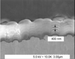
- FIG. 1 is a cross-sectional SEM image of an example of the negative electrode of the present invention
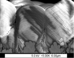
- 4 is a cross-sectional SEM image of another example of the negative electrode of the present invention.
- 1 is an exploded view showing a configuration example (laminate film type) of a lithium ion secondary battery including the negative electrode of the present invention.
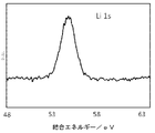
- FIG. 3 is part of the XPS spectrum of the surface layer of the negative electrode active material of Example 2.
- FIG. 3 is another part of the XPS spectrum of the negative electrode active material surface layer of Example 2.
- FIG. 4 is a surface SEM image of the negative electrode active material layer of Example 2 after charging and discharging.
- 3 is part of the XPS spectrum of the negative electrode active material layer of Example 2 after charging and discharging 20 times.
- Lithium ion secondary batteries using this silicon oxide are desired to have initial charge/discharge characteristics that are close to those of lithium ion secondary batteries using a carbonaceous active material. Also, by using Li-doped SiO, which can improve the initial charge/discharge characteristics, a significant increase in capacity can be expected.
- the present inventors have made intensive studies to obtain a negative electrode that can improve the initial charge-discharge characteristics and increase the battery capacity while obtaining high cycle characteristics when used as a negative electrode of a secondary battery. After repeating the above, the present invention was achieved.
- the present invention provides a negative electrode current collector having a roughened surface, A negative electrode having a negative electrode active material layer provided on the negative electrode current collector, The negative electrode active material layer contains negative electrode active material particles containing a compound of lithium, silicon, and oxygen, and the ratio O/Si of the oxygen to the silicon constituting the negative electrode active material particles is 0.8 or more1. is in the range of 2 or less,
- the negative electrode active material layer has a multilayer structure consisting of two or more layers, and each layer of the multilayer structure of the negative electrode active material layer has tetravalent silicon containing at least one of lithium and oxygen on the top.
- the present invention also provides a method for producing the negative electrode of the present invention, comprising: winding the negative electrode current collector on a can roll having a curvature; a step of vapor-phase-growing a film containing silicon and/or silicon monoxide having a multi-layer structure consisting of two or more layers on the negative electrode current collector while running the negative electrode current collector on the can roll; A step of blowing an oxygen-containing gas onto the film containing silicon and/or silicon monoxide to form a multilayer structure layer containing silicon dioxide on top of each layer; and doping lithium into the layer of the multilayer structure to form the negative electrode active material layer.
- FIG. 1 shows a schematic cross-sectional view of an example of the negative electrode of the present invention.
- the negative electrode 10 includes a negative electrode current collector 11 and a negative electrode active material layer 12 provided on a surface 11 a of the negative electrode current collector 11 .
- the negative electrode active material containing layer 12 may be provided on both surfaces 11a of the negative electrode current collector 11 as shown in FIG. 1, or may be provided only on one surface 11a.
- the surface 11a of the negative electrode current collector 11 is a roughened surface. That is, the negative electrode active material layer 12 is provided on the roughened surface 11 a of the negative electrode current collector 11 .
- the negative electrode current collector 11 and the negative electrode active material layer 12 will be described below.
- the negative electrode current collector 11 is made of an excellent conductive material and has high mechanical strength.
- Examples of conductive materials that can be used for the negative electrode current collector 11 include copper (Cu) and nickel (Ni). This conductive material is preferably a material that does not form an intermetallic compound with lithium (Li).
- the negative electrode current collector 11 preferably contains carbon (C) and sulfur (S) in addition to the main elements. This is because the physical strength of the negative electrode current collector is improved. This is because, in particular, in the case of having an active material layer that expands during charging, if the current collector contains the above element, it has the effect of suppressing deformation of the electrode including the current collector.
- the contents of the above-mentioned contained elements are not particularly limited, they are preferably 100 ppm by mass or less. This is because a higher deformation suppressing effect can be obtained. Cycle characteristics can be further improved by such a deformation suppression effect.
- the surface 11a of the negative electrode current collector 11 must be roughened, and desirably, the ten-point average roughness Rz of the surface is 1.5 ⁇ m or more and 5.0 ⁇ m or less.
- the negative electrode 10 including the negative electrode current collector 11 having the surface 11a with such a desirable average roughness Rz not only can the negative electrode active material layer 12 be supported more stably, but also the negative electrode active material layer 12 The density of the material particles can be made moderate, and as a result, better battery characteristics can be exhibited.
- the roughened negative electrode current collector 11 is, for example, a metal foil subjected to electrolytic treatment, embossing treatment, or chemical etching treatment.
- the negative electrode active material layer 12 of the negative electrode 10 of the present invention has negative electrode active material particles containing a compound of lithium, silicon, and oxygen, that is, silicon compound particles containing lithium and oxygen. is provided. It can be said that the negative electrode 10 has a structure in which negative electrode active material particles are directly supported on the roughened surface 11 a of the negative electrode current collector 11 .
- the negative electrode 10 of the present invention contains negative electrode active material particles that are silicon compound particles, the battery capacity can be improved.
- the negative electrode 10 of the present invention directly supports the negative electrode active material layer 12 on the roughened surface 11a of the negative electrode current collector 11 without using a binder, a conductive aid, or the like.
- the energy density of the electrode can be greatly improved because the area of the electrode that does not participate in charging and discharging can be reduced, and the excess voids can be reduced.
- the negative electrode 10 having the densely supported negative electrode active material layer 12 in this way, it is possible to increase the energy density of the battery, which cannot be achieved with, for example, a powder electrode.
- the ratio O/Si between oxygen and silicon constituting the negative electrode active material particles is in the range of 0.8 or more and 1.2 or less. If the ratio O/Si is 0.8 or more, the oxygen ratio is higher than that of simple silicon, so the cycle characteristics are good. A ratio O/Si of 1.2 or less is preferable because the resistance of the silicon oxide does not become too high.
- the composition of SiOx is preferably one in which x is close to 1. This is because high cycle characteristics can be obtained. Note that the composition of the silicon compound in the present invention does not necessarily mean 100% purity, and may contain trace amounts of impurity elements.
- the ratio O/Si is less than 0.8, the capacity increases, but the area where Si 0+ reacts with the electrolytic solution increases and the cycle characteristics deteriorate. Also, if the ratio O/Si exceeds 1.2, it becomes a load substance, and in this case also deteriorates the battery characteristics.
- the ratio O/Si is a molar ratio and should be as close to 1 as possible.
- the negative electrode active material layer 12 In order to introduce Li more smoothly, it is preferable to make the negative electrode active material layer 12 have a multi-layer structure consisting of two or more layers at the timing of forming the negative electrode active material layer 12 .
- the upper limit of the layers constituting the negative electrode active material layer 12 is not particularly limited.
- the negative electrode active material layer 12 can have a multi-layer structure consisting of 2 to 20 layers. This is because the negative electrode active material layer having a multilayer structure consisting of two or more layers can realize smooth insertion of Li while suppressing decomposition of the electrolytic solution. However, since it leads to an increase in the reaction area, the battery characteristics are insufficient as it is.
- each layer of the multilayer structure of the negative electrode active material layer 12 has a layer containing a tetravalent silicon compound containing at least one of lithium and oxygen in the upper portion. .
- this layer has not only the action of introducing and desorbing Li, but also the action of alleviating expansion and contraction during charging and discharging, so that the battery characteristics can be maintained.
- each layer can be Li-doped (Li-inserted), ion concentration is suppressed, and expansion occurs uniformly. Since Li detachment is also possible in each layer, shrinkage also occurs uniformly. As a result, expansion and contraction of the negative electrode due to charging and discharging can be alleviated, and a stable negative electrode active material layer can be maintained.
- the negative electrode 10 of the present invention it is possible to significantly increase the capacity while maintaining excellent battery characteristics, particularly excellent cycle characteristics.
- the tetravalent silicon compound preferably contains one or more selected from SiO 2 and Li 4 SiO 4 . This is because SiO 2 can further reduce the expansion and contraction of the negative electrode, and Li 4 SiO 4 can allow charging and discharging to proceed more smoothly.
- negative electrode active material particles having a compound of lithium, silicon, and oxygen can exist adjacent to each other. At least carbon atoms and oxygen atoms are chemically bonded between the particles and on the surface of the negative electrode active material particles, and a composite compound (“C, O It is preferably filled with a compound (also called "compound").
- This composite compound serves as a protective layer that protects the interface between the negative electrode active material layer and the electrolyte.
- the above composite compound that acts as a protective layer that suppresses the reaction with the electrolyte By filling the interparticle and surface layer of the negative electrode active material particles with the above composite compound that acts as a protective layer that suppresses the reaction with the electrolyte, the decomposition of the electrolyte is suppressed, Li is easily introduced, and the battery characteristics are maintained.
- the negative electrode active material layer 12 can be proposed. Due to the presence of such a complex compound, better cycle characteristics can be exhibited.
- the primary particles of the negative electrode active material particles have a multi-layered structure, and the interlayer portions thereof are similarly filled with the composite compound, thereby ensuring reactivity with the electrolytic solution. .
- the composite compound acting as a protective layer is a ring-opening decomposition product of a composite of an ether solvent and a polyphenylene compound or a polycyclic aromatic compound, or a ring-opening decomposition product of a composite in which the composite forms a complex with lithium.
- Such a composite compound can be easily formed in the process of Li-doping the negative electrode active material particles using an oxidation-reduction method.
- the composite compound in which at least carbon atoms and oxygen atoms are chemically bonded which can act as a protective layer, partially contains lithium. That is, the composite compound preferably contains lithium at least in part.
- the composite compound By compounding a composite oxide containing carbon and oxygen with lithium and containing lithium in a part of it, it behaves like a kind of solid electrolyte, and in particular, the permeation of Li is higher than when it contains only carbon and oxygen. Since it becomes possible to make it easy to occur and the diffusibility of Li can be improved, the battery characteristics can be further improved.
- Silicon monoxide which is represented by general silicon oxides, is often expressed as a compound of 0 to 4 valences of Si.
- Si2p spectrum of silicon monoxide is obtained by photoelectron spectroscopy, the peak of Si 0+ appears near the binding energy of 99 eV, and the peak of Si 4+ appears near the binding energy of 103 eV. It shows a spectrum in which the 0-valence state and the Si 4+ state are dominant.
- the negative electrode active material particles containing silicon are directly supported on the negative electrode current collector 11, the state of the roughened portion of the surface 11a of the negative electrode current collector 11, the temperature of the negative electrode current collector 11 (substrate on which vapor deposition is performed), and the negative electrode
- the structure of the silicon compound can be changed by controlling the traveling speed of the current collector 11, gas ejection, and the like.
- the negative electrode active material particles are repeatedly charged and discharged, for example, after charging and discharging at least 20 times, the particles have silicon in the Si 0+ state and silicon in the compound state of Si 1+ to Si 3+ .
- the compound state of Si 1+ to Si 3+ is most desirable.
- the upper limit of the number of times of charging and discharging in such a compound state is not particularly limited. It is desirable to have silicon in the 3+ compound state.
- the state of the valence of silicon in the negative electrode active material particles is determined by subjecting the photoelectron spectrum obtained by the photoelectron spectroscopy to a waveform separation process and confirming the presence or absence of a peak attributed to each valence state of silicon in the spectrum. , can be determined.
- the valence state of silicon in the negative electrode active material layer and the negative electrode active material particles contained therein can be confirmed, for example, by using a scanning X-ray photoelectron spectrometer PHI Quantera II manufactured by ULVAC-PHI. At this time, the X-ray beam diameter is 100 ⁇ m, and a neutralization gun can be used.
- the negative electrode active material particles grow in vapor phase from the roughened portion of the surface 11a of the negative electrode current collector 11 .
- these particles are defined as primary particles, it is preferable that secondary particles, which are aggregates of the primary particles, are formed after charging and discharging.
- Si 0+ constituting the negative electrode active material layer before charging and discharging is desirably non-crystalline (amorphous) as much as possible.
- the crystallite size of Si(111) is desirably 1.0 nm or less. Therefore, the negative electrode active material particles have a peak due to the Si (111) crystal plane obtained by X-ray diffraction using Cu—K ⁇ rays before charging and discharging, and the crystallite size corresponding to this crystal plane is It is desirable to be 1.0 nm or less. If the battery contains such negative electrode active material particles, the reactivity with the electrolytic solution can be suppressed, and the battery characteristics can be further improved. Ideally, the crystallite size of Si(111) is 0 nm.
- the degree of enlargement of Li silicate and the degree of crystallization of Si can be confirmed by XRD (X-ray Diffraction).
- XRD measurement can be performed, for example, under the following conditions.
- As an X-ray diffractometer, for example, D8 ADVANCE manufactured by Bruker can be used.
- the X-ray source was Cu K ⁇ rays, using a Ni filter, an output of 40 kV/40 mA, a slit width of 0.3°, a step width of 0.008°, and a counting time of 0.15 seconds per step from 10-40°. Measure up to
- FIG. 1 A diagrammatic representation of the negative electrode of the present invention.
- FIGS. 2 and 3 are respectively cross-sectional SEM images of an example of the negative electrode of the present invention.
- a member with a raised surface shown in the lower region of FIGS. 2 and 3 is a negative electrode current collector having a roughened surface.
- the ten-point average roughness Rz of the surface of the negative electrode current collector shown in FIG. 3 is larger than the ten-point average roughness Rz of the surface of the negative electrode current collector shown in FIG.
- the portions that grow fan-shaped around the bumps on the roughened surface of the negative electrode current collector are the negative electrode active material particles.
- the negative electrode active material particles constitute a negative electrode active material layer having a multilayer structure. In the example shown in FIG. 2, the thickness of each layer of the negative electrode active material layer is about 400 nm. Note that the negative electrode shown in FIG. 3 has a larger number of negative electrode active material layers than the negative electrode shown in FIG.
- This portion is a layer containing a tetravalent silicon compound containing at least one of lithium and oxygen.
- a decomposed product of the solvent is generated by performing Li doping, and fine voids are present.
- the negative electrode active material layer of the negative electrode of the present invention has very few voids and contains densely packed negative electrode active material particles.
- the method for producing a negative electrode according to the present invention includes the step of winding the negative electrode current collector on a can roll having a curvature, and, while running the negative electrode current collector on the can roll, on the negative electrode current collector, 2 a step of vapor-phase growing a film containing silicon and/or silicon monoxide having a multi-layer structure consisting of at least one layer;
- the method comprises the steps of: forming a multilayer structure layer containing silicon dioxide; and doping the multilayer structure layer with lithium to form the negative electrode active material layer.
- the negative electrode of the present invention can be manufactured by the method of manufacturing the negative electrode of the present invention.
- the method for producing the negative electrode of the present invention is not limited to the production method of the present invention described here.
- a film containing silicon and/or silicon monoxide with a multi-layered structure consisting of two or more layers is manufactured.
- a film containing silicon and/or silicon monoxide having a multilayer structure is vapor-grown on the negative electrode current collector.
- a film containing silicon can contain silicon particles.
- a film containing silicon monoxide can contain silicon monoxide particles that are silicon compound (silicon oxide) particles containing oxygen.
- a film containing silicon and/or silicon monoxide having a multilayer structure consisting of two or more layers can contain silicon-containing particles.
- This multilayer film containing silicon and/or silicon monoxide is a negative electrode current collector having a roughened surface, for example, a surface with a ten-point average roughness Rz of 1.5 ⁇ m or more and 5.0 ⁇ m or less (for example, 2.5 ⁇ m). ) by depositing, for example, a silicon vapor stream or silicon oxide gas onto a roughened foil (eg, a roughened copper foil).
- the negative electrode current collector is wound on a curved can roll.
- the curvature (R) of the can roll is preferably, for example, 4 m ⁇ 1 or more and 20 m ⁇ 1 or less.
- a film of silicon monoxide can be formed, for example, by the following procedure. First, a raw material that generates silicon oxide gas is heated at a temperature of 1100° C. or higher under reduced pressure to generate silicon oxide gas. At this time, a mixture of metal silicon powder and silicon dioxide powder can be used as the raw material. Considering the presence of oxygen on the surface of the metallic silicon powder and a trace amount of oxygen in the reactor, the mixing molar ratio is preferably in the range of 0.9 ⁇ metallic silicon powder/silicon dioxide powder ⁇ 1.2.
- the silicon oxide gas generated as described above is deposited on the roughened portion of the surface of the negative electrode current collector and becomes primary particles having a columnar structure.
- the silicon film can be formed, for example, by vapor deposition using metal silicon.
- the structure of the primary particles can also be changed by changing the roughened structure of the surface of the negative electrode current collector.
- the solidification heat during deposition and the radiant heat from the heating section promote crystallization of the negative electrode active material layer.
- film formation is performed while the negative electrode current collector is running on a can roll having a curvature.
- the vapor phase epitaxy can be performed while reducing the heat load so as not to cause crystallization of Si.
- silicon oxide is sublimable unlike silicon, so it can be deposited at an early stage, and there is no concern about receiving radiant heat from molten silicon, which is a problem with silicon films. Therefore, it is suitable for forming active materials by vapor deposition. It can be said that there are
- multilayer film formation for example, reciprocating multilayer film formation
- the negative electrode current collector is running on a can roll having a curvature
- a part of the surface of each layer is obliquely deposited and voids are formed. occurs.
- Vapor deposition can also be performed on both roughened surfaces of the negative electrode current collector. For example, vapor deposition is performed on one roughened surface of the negative electrode current collector, then the negative electrode current collector is turned over, and vapor deposition is performed on the other roughened surface of the negative electrode current collector. can also
- a gas containing oxygen is blown onto the film containing silicon and/or silicon monoxide formed as described above to form a multi-layered layer containing silicon dioxide on top of each layer.
- the gas containing oxygen is not particularly limited as long as it contains oxygen, but it can be nitrogen gas containing oxygen, for example.
- oxygen-containing gas By blowing oxygen-containing gas, oxygen enters the gaps above each layer, and oxygen can be introduced into each layer. This also allows at least part of the silicon and/or silicon monoxide to be converted to silicon dioxide on top of each layer. In other words, by blowing oxygen-containing gas, it is possible to form layers having a multi-layer structure in which each layer contains a silicon oxide containing silicon dioxide.
- Li is doped (inserted) into the multilayer structure layer containing silicon dioxide on top of each layer produced as described above.
- a negative electrode active material layer containing negative electrode active material particles containing silicon oxide particles into which lithium is inserted is obtained.
- this modifies the silicon oxide particles and produces a Li compound inside the silicon oxide particles.
- the insertion of Li is preferably performed by an oxidation-reduction method.
- lithium can be inserted by first immersing the negative electrode active material layer containing silicon oxide particles in a solution A in which lithium is dissolved in an ether solvent.
- This solution A may further contain a polycyclic aromatic compound or a linear polyphenylene compound.
- active lithium can be desorbed from the silicon oxide particles by immersing the silicon active material particles in a solution B containing a polycyclic aromatic compound or a derivative thereof.
- Solvents for this solution B can be, for example, ether solvents, ketone solvents, ester solvents, alcohol solvents, amine solvents, or mixed solvents thereof.
- the obtained silicon active material particles may be heat-treated under an inert gas.
- the heat treatment can stabilize the Li compound. After that, it may be washed with alcohol, alkaline water in which lithium carbonate is dissolved, weak acid, pure water, or the like.
- Ether solvents used for solution A include diethyl ether, tert-butyl methyl ether, tetrahydrofuran, dioxane, 1,2-dimethoxyethane, diethylene glycol dimethyl ether, triethylene glycol dimethyl ether, tetraethylene glycol dimethyl ether, or mixed solvents thereof. can be used. Among these, it is particularly preferable to use tetrahydrofuran, dioxane, and 1,2-dimethoxyethane. These solvents are preferably dehydrated and preferably deoxygenated.
- polycyclic aromatic compound contained in the solution A one or more of naphthalene, anthracene, phenanthrene, naphthacene, pentacene, pyrene, picene, triphenylene, coronene, chrysene and derivatives thereof can be used.
- chain polyphenylene compound one or more of biphenyl, terphenyl, and derivatives thereof can be used.
- polycyclic aromatic compound contained in solution B one or more of naphthalene, anthracene, phenanthrene, naphthacene, pentacene, pyrene, picene, triphenylene, coronene, chrysene, and derivatives thereof can be used.
- ether-based solvent for solution B diethyl ether, tert-butyl methyl ether, tetrahydrofuran, dioxane, 1,2-dimethoxyethane, diethylene glycol dimethyl ether, triethylene glycol dimethyl ether, tetraethylene glycol dimethyl ether, and the like can be used. .
- Acetone, acetophenone, etc. can be used as the ketone-based solvent.
- ester solvent methyl formate, methyl acetate, ethyl acetate, propyl acetate, isopropyl acetate, and the like can be used.
- Methanol, ethanol, propanol, isopropyl alcohol, etc. can be used as alcohol-based solvents.
- amine-based solvent methylamine, ethylamine, ethylenediamine, etc. can be used.
- a negative electrode current collector and a multilayered negative electrode active material layer provided on the negative electrode current collector wherein each layer of the multilayered structure contains at least one of lithium and oxygen on the top thereof. It is possible to obtain a negative electrode including a negative electrode active material layer having a layer containing a compound of tetravalent silicon containing
- the ratio O/Si of oxygen and silicon constituting the negative electrode active material contained in the negative electrode active material layer can be adjusted, for example, by the film formation rate during multilayer film formation and the amount of oxygen sprayed after film formation.
- the negative electrode of the present invention can be produced as described above.
- the composite compound in which at least a carbon atom and an oxygen atom are chemically bonded which can be filled between the particles and in the surface layer of the negative electrode active material particles, is, for example, an ether solvent and a polyphenylene compound or a polycyclic compound contained in the solution A.
- a complex of aromatic compounds undergoes ring-opening decomposition, etc., or a complex in which the complex forms a complex with lithium (for example, a polycyclic aromatic compound complexed with Li and a complex with an ether solvent substance) can be formed by performing ring-opening decomposition and the like.
- the state of the filling film (composite compound) can be controlled.
- a complex compound generated in this way can also contain multiple types of compounds.
- the step of forming the negative electrode active material layer by immersing the multilayer structure layer obtained by blowing oxygen-containing gas in a lithium-containing solution, silicon oxide is reformed by oxidation-reduction method.
- lithium, silicon, and a compound containing oxygen, and at least carbon atoms and oxygen atoms are chemically bonded between the particles of the negative electrode active material particles and in the surface layer of the negative electrode active material layer, and the negative electrode active material layer It is also possible to form complex compounds that do not alloy with the material particles.
- the negative electrode of the present invention can be used as a negative electrode for non-aqueous electrolyte secondary batteries such as lithium ion secondary batteries.
- the wound electrode body 31 has a separator between the positive electrode and the negative electrode and is wound. There is also a case where a laminate having a separator between the positive electrode and the negative electrode is housed without being wound.
- a positive electrode lead 32 is attached to the positive electrode and a negative electrode lead 33 is attached to the negative electrode. The outermost periphery of the electrode body is protected by a protective tape.
- the positive electrode lead 32 and the negative electrode lead 33 are, for example, led out in one direction from the inside of the exterior member 35 toward the outside.
- the positive electrode lead 32 is made of a conductive material such as aluminum
- the negative electrode lead 33 is made of a conductive material such as nickel or copper.
- the exterior member 35 is, for example, a laminate film in which a fusion layer, a metal layer, and a surface protection layer are laminated in this order.
- the outer peripheral edges of the fusion layer are fused together or adhered to each other with an adhesive or the like.
- the fused portion is, for example, a film such as polyethylene or polypropylene, and the metal portion is aluminum foil or the like.
- the protective layer is, for example, nylon or the like.
- An adhesive film 34 is inserted between the exterior member 35 and each of the positive electrode lead 32 and the negative electrode lead 33 to prevent outside air from entering.
- This material is, for example, polyethylene, polypropylene, polyolefin resin.
- the positive electrode has, for example, a positive electrode active material layer on both sides or one side of the positive electrode current collector, like the negative electrode 10 in FIG.
- the positive electrode current collector is made of a conductive material such as aluminum, for example.
- the positive electrode active material layer contains one or more of positive electrode materials (positive electrode active materials) capable of intercalating and deintercalating lithium ions. It may contain other materials such as
- a lithium-containing compound is desirable as the positive electrode material.
- the lithium-containing compound include a composite oxide composed of lithium and a transition metal element, or a phosphate compound containing lithium and a transition metal element.
- these positive electrode materials compounds containing at least one of nickel, iron, manganese and cobalt are preferred.
- These chemical formulas are represented by, for example, Li x M1O 2 or Li y M2PO 4 .
- M1 and M2 represent at least one transition metal element.
- the values of x and y vary depending on the state of charge and discharge of the battery, they are generally represented by 0.05 ⁇ x ⁇ 1.10 and 0.05 ⁇ y ⁇ 1.10.
- Examples of composite oxides containing lithium and a transition metal element include lithium-cobalt composite oxides (Li x CoO 2 ), lithium-nickel composite oxides (Li x NiO 2 ), lithium-nickel-cobalt composite oxides, and the like. .
- Examples of lithium-nickel-cobalt composite oxides include lithium-nickel-cobalt-aluminum composite oxides (NCA) and lithium-nickel-cobalt-manganese composite oxides (NCM).
- Phosphate compounds containing lithium and a transition metal element include, for example, lithium iron phosphate compounds (LiFePO 4 ) and lithium iron manganese phosphate compounds (LiFe 1-u Mn u PO 4 (0 ⁇ u ⁇ 1)). is mentioned.
- LiFePO 4 lithium iron phosphate compounds
- LiFe 1-u Mn u PO 4 (0 ⁇ u ⁇ 1) lithium iron manganese phosphate compounds
- polymeric materials include polyvinylidene fluoride, polyimide, polyamideimide, aramid, polyacrylic acid, lithium polyacrylate, sodium polyacrylate, and carboxymethylcellulose.
- Synthetic rubbers include, for example, styrene-butadiene-based rubber, fluorine-based rubber, and ethylene propylene diene.
- one or more of carbon materials such as carbon black, acetylene black, graphite, ketjen black, carbon nanotubes, and carbon nanofibers can be used as the positive electrode conductive aid.
- the negative electrode of the present invention is used as the negative electrode of the secondary battery.
- the negative electrode constituting the secondary battery preferably has a larger negative electrode charge capacity than the electric capacity (charge capacity as a battery) obtained from the positive electrode active material. Thereby, deposition of lithium metal on the negative electrode can be suppressed.
- the positive electrode active material layer is provided on part of both surfaces of the positive electrode current collector, and similarly the negative electrode active material layer of the present invention is also provided on part of both surfaces of the negative electrode current collector.
- the negative electrode active material layer provided on the negative electrode current collector has a region where the facing positive electrode active material layer does not exist. This is for the purpose of stably designing a battery.
- the separator separates the lithium metal or the positive electrode from the negative electrode, and allows lithium ions to pass through while preventing current short circuit due to contact between the two electrodes.
- This separator is formed of a porous film made of synthetic resin or ceramic, for example, and may have a laminated structure in which two or more kinds of porous films are laminated.
- synthetic resins include polytetrafluoroethylene, polypropylene, and polyethylene.
- Electrode At least part of each of the positive electrode active material layer and the negative electrode active material layer, or the separator is impregnated with a liquid non-aqueous electrolyte (electrolytic solution).
- electrolytic solution has an electrolytic salt dissolved in a solvent, and may contain other materials such as additives.
- Non-aqueous solvents include, for example, ethylene carbonate, propylene carbonate, butylene carbonate, dimethyl carbonate, diethyl carbonate, ethylmethyl carbonate, methylpropyl carbonate, 1,2-dimethoxyethane, tetrahydrofuran and the like.
- ethylene carbonate, propylene carbonate, dimethyl carbonate, diethyl carbonate, and ethylmethyl carbonate it is desirable to use at least one of ethylene carbonate, propylene carbonate, dimethyl carbonate, diethyl carbonate, and ethylmethyl carbonate. This is because better characteristics are obtained.
- the solvent contains at least one of a halogenated chain carbonate or a halogenated cyclic carbonate.
- a halogenated chain carbonate is a chain carbonate having halogen as a constituent element (at least one hydrogen is substituted with halogen).
- a halogenated cyclic carbonate is a cyclic carbonate having halogen as a constituent element (that is, at least one hydrogen is substituted with halogen).
- halogen is not particularly limited, but fluorine is preferred. This is because it forms a better film than other halogens. Moreover, the larger the number of halogens, the better. This is because the coating obtained is more stable and the decomposition reaction of the electrolyte is reduced.
- halogenated chain carbonates include fluoromethylmethyl carbonate and difluoromethylmethyl carbonate.
- Halogenated cyclic carbonates include 4-fluoro-1,3-dioxolan-2-one and 4,5-difluoro-1,3-dioxolan-2-one.
- an unsaturated carbon-bonded cyclic carbonate As a solvent additive, it is preferable to contain an unsaturated carbon-bonded cyclic carbonate. This is because a stable film is formed on the surface of the negative electrode during charging and discharging, and the decomposition reaction of the electrolytic solution can be suppressed.
- unsaturated carbon-bonded cyclic ester carbonates include vinylene carbonate and vinylethylene carbonate.
- sultone cyclic sulfonate
- solvent additive examples include propane sultone and propene sultone.
- the solvent preferably contains an acid anhydride. This is because the chemical stability of the electrolytic solution is improved.
- Acid anhydrides include, for example, propanedisulfonic anhydride.
- the electrolyte salt can include, for example, any one or more of light metal salts such as lithium salts.
- lithium salts include lithium hexafluorophosphate (LiPF 6 ) and lithium tetrafluoroborate (LiBF 4 ).
- the content of the electrolyte salt is preferably 0.5 mol/kg or more and 2.5 mol/kg or less with respect to the solvent. This is because high ionic conductivity can be obtained.
- the laminated film type secondary battery described above can be manufactured, for example, by the following procedure.
- a positive electrode is produced using the positive electrode material described above.
- a positive electrode active material and, if necessary, a positive electrode binder, a positive electrode conductive aid, and the like are mixed to form a positive electrode mixture, which is then dispersed in an organic solvent to obtain a positive electrode mixture slurry.
- the mixture slurry is applied to the positive electrode current collector with a coating device such as a die coater having a knife roll or a die head, and dried with hot air to obtain a positive electrode active material layer.
- the positive electrode active material layer is compression-molded using a roll press machine or the like. At this time, heating may be performed, and compression may be repeated multiple times.
- a negative electrode is manufactured by forming a negative electrode active material layer on the negative electrode current collector according to the same work procedure as that for manufacturing the negative electrode 10 described above.
- each active material layer is formed on both sides of the positive electrode and negative electrode current collectors. At this time, the active material coating lengths on both sides of both electrodes may be displaced (see FIG. 1).
- the cathode lead 32 is attached to the cathode current collector, and the anode lead 33 is attached to the anode current collector.
- the positive electrode and the negative electrode are laminated with a separator interposed therebetween, and then wound to produce the wound electrode body 31, and a protective tape is adhered to the outermost periphery thereof.
- the wound electrode body 31 is molded so as to have a flat shape.
- the insulating portions of the exterior members are bonded together by a heat-sealing method, and the wound electrode body is opened in only one direction.
- the body 31 is encapsulated. Subsequently, the adhesion film 34 is inserted between the positive electrode lead 32 and the negative electrode lead 33 and the exterior member 35 . Subsequently, a predetermined amount of the electrolyte prepared as described above is introduced from the open portion, and vacuum impregnation is performed. After impregnation, the release portion is adhered by a vacuum heat-sealing method. As described above, the laminate film type secondary battery 30 can be manufactured.
- the negative electrode utilization rate during charging and discharging is preferably 93% or more and 99% or less. If the negative electrode utilization rate is in the range of 93% or more, the first charge efficiency does not decrease, and the battery capacity can be greatly improved. In addition, if the negative electrode utilization rate is in the range of 99% or less, the safety can be ensured without precipitation of Li.
- the negative electrode of Comparative Example 1 is composed of artificial graphite: conductive agent (acetylene black): SBR (styrene-butadiene rubber): CMC (carboxymethyl cellulose), 95.7% by mass: 1% by mass: 1.8% by mass: 1 It was formed by mixing at a ratio of 0.5% by mass.
- conductive agent acetylene black
- SBR styrene-butadiene rubber
- CMC carboxymethyl cellulose
- the electrode of Comparative Example 2 was prepared by mixing Li—SiO—C: PAA—Na (sodium polyacrylate): Conductive agent (acetylene black) at a ratio of 90% by mass: 8% by mass: 2% by mass. .
- Li-Si-O was prepared by the following procedure. First, silicon and silicon dioxide were mixed as raw materials, vaporized at 1300° C., deposited on a deposition substrate, and quenched to prepare an SiO mass. This SiO lump was pulverized to a median diameter of 7 ⁇ m, and then doped with Li using an oxidation-reduction method. After doping, a heat treatment was performed to prepare a sample in order to stabilize the Li silicate.
- Comparative Examples 3-7 and Examples 1-4 negative electrodes were produced by the following procedure.
- a surface-roughened copper foil having a surface ten-point average roughness (roughness) Rz of 2.5 ⁇ m was used as the negative electrode current collector.
- Example 1 and Comparative Example 5 Preparation of negative electrode precursor
- gravel-like metal silicon was placed in a carbon crucible, and silicon was melted and vaporized using an electron gun under vacuum.
- a surface-roughened copper foil (to be a negative electrode current collector) is wound on a can roll having a curvature R of 10 m ⁇ 1 , and the surface-roughened copper foil is reciprocated on the can roll to travel.
- a silicon film having a five-layer structure was formed on the surface-roughened copper foil.
- Example 1 nitrogen gas containing oxygen was blown onto the silicon film after forming a five-layered silicon film. As a result, a multi-layer structure layer containing silicon dioxide was formed on top of each layer.
- Example 1 and Comparative Example 5 the film formation rate and the The amount of oxygen sprayed was adjusted. Thus, negative electrode precursors of Example 1 and Comparative Example 5 were produced.
- Comparative Example 3 a silicon film having a five-layer structure was formed in the same manner as in Example 1, but the subsequent blowing of nitrogen gas containing oxygen was not performed. Thus, a negative electrode precursor of Comparative Example 3 was produced.
- Comparative Example 4 metallic silicon and silicon dioxide were placed in a carbon crucible and heated to 1200° C. in a vacuum atmosphere of 10 ⁇ 2 Pa to extract vapor. The vapor was carried directly on the roughened copper foil in the same manner as in Comparative Example 3.
- Example 2 and 3 and Comparative Example 6 a raw material in which metallic silicon and silicon dioxide were mixed was introduced into the furnace and vaporized in a vacuum atmosphere of 10 ⁇ 2 Pa.
- a surface-roughened copper foil (to be a negative electrode current collector) is wound on a can roll having a curvature R of 10 m ⁇ 1 , and the surface-roughened copper foil is reciprocated on the can roll to travel.
- a silicon monoxide film having a five-layer structure was formed on the surface-roughened copper foil.
- Example 3 and Comparative Example 6 the film formation rate was adjusted so that the ratio O/Si between silicon and oxygen constituting the finally obtained negative electrode active material particles was the numerical value shown in the table below. Film formation was carried out by blowing hydrogen or oxygen into steam as needed. Further, in Examples 2 and 3 and Comparative Example 6, after the film formation, the ratio O/Si of silicon and oxygen constituting the finally obtained negative electrode active material particles was the numerical value shown in the table below. The oxygen blowing amount was adjusted. Thus, negative electrode precursors of Examples 2 and 3 and Comparative Example 6 were produced.
- Example 4 (Example 4 and Comparative Example 7)
- Example 4 a negative electrode precursor of Example 4 was produced in the same manner as in Example 2, except that a multilayer film of 20 layers was formed by controlling the film formation rate.
- Comparative Example 7 a negative electrode precursor of Comparative Example 7 was produced in the same manner as in Example 2, except that one layer of monolayer film formation was performed without running the roughened copper foil.
- Examples 1-4, and Comparative Examples 3 and 5-7 The negative electrode precursors obtained in Examples 1 to 4 and Comparative Examples 3 and 5 to 7 were sufficiently cooled and taken out, and an ether-based solvent with a water content reduced to 50 ppm by mass was used, and an oxidation-reduction method was performed. A silicon compound was modified by inserting lithium into it. As a result, the negative electrodes of Examples 1 to 4 and Comparative Examples 3 and 5 to 7 including the negative electrode active material layer after lithium insertion were obtained.
- the negative electrode active material layers after lithium insertion obtained in Examples 1 to 4 and Comparative Examples 3 and 5 to 7 were observed with a scanning electron microscope (SEM). It was confirmed that the space between the negative electrode active material layers of Nos. 5 and 6 was dark. The presence of a dark portion was also confirmed in the upper portion of the single-layer negative electrode active material layer of Comparative Example 7. The dark areas are easily electrified areas, and it can be seen that silicon is oxidized to form a layer with many tetravalent states.
- Comparative Example 7 The negative electrode active material layers after lithium insertion obtained in Examples 1 to 4 and Comparative Examples 3 and 5 to 7 were analyzed by X-ray photoelectron spectroscopy (XPS) to determine that carbon atoms and oxygen The presence of a filling layer containing a composite compound in which atoms are chemically bonded is confirmed, and the valence state of silicon on the surface of the negative electrode active material particles and the ratio O/Si of silicon and oxygen constituting the negative electrode active material particles are investigated. rice field.
- XPS X-ray photoelectron spectroscopy
- the negative electrode active material layers after lithium insertion obtained in Examples 1 to 4 and Comparative Examples 3 and 5 to 7 consisted of negative electrode active material particles having a compound of lithium, silicon, and oxygen, and negative electrode active material. It was found that there is a filling layer containing a composite compound in which carbon atoms and oxygen atoms are chemically bonded, which is filled between the particles and in the surface layer of the.
- Example 2 shown in FIGS. It can be seen that a layer containing a tetravalent Si compound containing lithium and oxygen is present in the surface layer portion (upper portion) of each layer of the negative electrode active material layer of Example 2. This confirmed the presence of SiO 2 and Li 4 SiO 4 . It was confirmed that the negative electrodes of Examples 1 and 3 also had a layer containing a tetravalent Si compound containing lithium and oxygen on top of each layer of the negative electrode active material layer.
- Example 5 In Example 5, after the Li insertion electrode was obtained in the same manner as in Example 2, it was washed with ether containing 10% water to remove the surface filling layer. Thus, a negative electrode of Example 5 was obtained.
- Examples 6-8) In Examples 6 to 8, the film formation distance, the film formation rate, and the thickness of the copper foil were adjusted so that the crystallite size resulting from the Si (111) crystal plane contained in the negative electrode active material particles was the value shown in Table 2 below.
- Each negative electrode was produced in the same manner as in Example 2, except that film formation was performed by adjusting the running speed and the opening with which the vapor deposition flow was in contact.
- each negative electrode was produced in the same manner as in Example 2, except that the roughness Rz of the surface-roughened copper foil was changed between 0.5 ⁇ m and 7 ⁇ m as shown in Table 2 below. bottom.
- the negative electrode active material layers after lithium insertion obtained in Examples 5 to 14 consisted of negative electrode active material particles having a compound of lithium, silicon, and oxygen, and particles filled between the particles of the negative electrode active material and on the surface layer. and a filling layer containing a composite compound in which carbon atoms and oxygen atoms are chemically bonded, and the ratio O/Si of silicon and oxygen constituting the negative electrode active material particles is 0.8 or more and 1.2 or less.
- the negative electrode active material layers of the negative electrodes of Examples 5 to 14 had a five-layer structure as in Example 2, and above each layer was a layer containing a tetravalent Si compound containing lithium and oxygen. I confirmed that
- ethylene carbonate (EC) and dimethyl carbonate (DMC) are mixed to prepare a non-aqueous solvent, and an electrolyte salt (lithium hexafluorophosphate: LiPF 6 ) is dissolved in the non-aqueous solvent to prepare an electrolyte solution.
- an electrolyte salt lithium hexafluorophosphate: LiPF 6
- an electrolyte salt lithium hexafluorophosphate: LiPF 6
- the previously obtained negative electrode was punched to a diameter of 15 mm, and this was placed face to face with a Li foil attached to an aluminum clad with a separator interposed therebetween. After electrolyte injection, a 2032 coin battery was produced.
- the initial efficiency was measured under the following conditions. First, the prepared coin battery for the initial efficiency test was charged (initial charge) in the CCCV mode at a charge rate equivalent to 0.03C. CV was 0 V and final current was 0.04 mA. Next, CC discharge (initial discharge) was performed at a discharge rate of 0.03 C and a discharge final voltage of 1.2 V.
- initial efficiency (initial discharge capacity/initial charge capacity) ⁇ 100.
- the counter-positive electrode was designed so that the utilization rate of the negative electrode was 95%.
- the cycle characteristics were investigated as follows. First, two cycles of charge and discharge were performed at 0.2C in an atmosphere of 25°C for battery stabilization, and the discharge capacity of the second cycle was measured. Battery cycle characteristics were calculated from the discharge capacity at the 3rd cycle, and the battery test was stopped at 100 cycles. Charging and discharging were performed at 0.7C for charging and 0.5C for discharging. The charge voltage was 4.3V, the discharge final voltage was 2.5V, and the charge final rate was 0.07C.
- the discharge capacity at the second cycle measured in the cycle characteristics test was taken as the capacity achieved by each negative electrode.
- FIG. 7 shows an SEM image of the negative electrode active material layer of the negative electrode of Example 2 after charging and discharging (post-discharging state).
- Example 2 [XPS spectrum after charging and discharging 20 times]
- the negative electrode of Example 2 was subjected to XPS analysis after being charged and discharged 20 times. A part of the obtained XPS spectrum is shown in FIG.
- the XPS spectrum of the negative electrode active material layer of the negative electrode of Example 2 after charging and discharging 20 times shows a peak attributed to silicon in a zero valence state near 99 eV and a peak near 101.9 eV.
- a broad peak attributed to silicon in the compound state of Si 1+ to Si 3+ was included as an apex.
- Tables 1 and 2 show the rate of increase in discharge capacity per volume (Wh/L) relative to Comparative Example 1 as the rate of increase in capacity.
- the negative electrode of Comparative Example 2 produced using powdered Li-doped SiO had a lower capacity than the negative electrodes of Examples 1-14. This is probably because the negative electrode of Comparative Example 2 contained a binder not involved in charge and discharge because powder was used instead of vapor deposition, and there were many extra voids.
- the negative electrode of Comparative Example 3 was significantly inferior in cycle characteristics compared to Examples 1-14.
- no oxygen-containing gas was blown to the five-layered silicon film. Therefore, each layer of the negative electrode active material layer of the negative electrode of Comparative Example 3 did not have a layer containing a tetravalent silicon compound containing at least one of lithium and oxygen on the upper portion. Therefore, in the negative electrode of Comparative Example 3, ion concentration occurred in a part of the negative electrode active material layer during charging and discharging, and expansion and contraction of the negative electrode due to charging and discharging caused deterioration of the negative electrode.
- Comparative Example 4 had a lower capacity increase rate per volume. This is probably because in Comparative Example 4, Li was not inserted into the silicon oxide.
- Comparative Examples 5 and 6 and Examples 1 to 3 are examples in which the amount of oxygen in the bulk (oxygen ratio O/Si) was adjusted.
- silicon oxide is produced from silicon and silicon dioxide, it is difficult to increase or decrease the amount of oxygen.
- silicon oxide (Comparative Example 5) having a ratio O/Si of 0.7 could not control the valence, resulting in a large amount of silicon elements remaining.
- the negative electrode of Comparative Example 5 had lower cycle characteristics than the negative electrodes of Examples 1 to 3 as a result of setting the oxygen ratio O/Si to 0.7. This is probably because in the negative electrode of Comparative Example 5, the oxygen ratio O/Si was set to 0.7, so that the area where the zero-valent Si reacted with the electrolytic solution was too large.
- the negative electrode of Comparative Example 6 had a lower initial efficiency than the negative electrodes of Examples 1 to 3 as a result of setting the oxygen ratio O/Si to 1.3. This is probably because the negative electrode of Comparative Example 6 had an oxygen ratio O/Si of 1.3, which resulted in an excessive amount of load substances.
- the negative electrode of Comparative Example 7 had significantly deteriorated cycle characteristics. This is probably because the single-layer film was formed by depositing the silicon oxide film without running the roughened copper foil, which made it impossible to alleviate the expansion and contraction of the negative electrode.
- Examples 6 to 9 are examples of examining the influence of silicon crystallization on battery characteristics.
- the negative electrodes of Examples 6-9 were able to increase the capacity more than the negative electrode of Comparative Example 1 while maintaining the battery characteristics better than those of Comparative Examples 2-7.
- Example 2 in which silicon was amorphous, exhibited better battery characteristics than the negative electrodes of Examples 6 to 9, in which silicon was highly crystallized.
- Examples 9 to 14 shown in Table 2 are examples aimed at finding the most suitable point by adjusting the surface roughness Rz of the surface-roughened copper foil as the negative electrode current collector.
- Example 2 and Examples 9 to 14 From the results of Example 2 and Examples 9 to 14, the negative electrodes of Examples 2 and 10 to 13, in which the surface roughness Rz of the surface-roughened copper foil is 1.5 ⁇ m or more and 5.0 ⁇ m or more, have a roughness It can be seen that the negative electrode of Example 9, in which Rz is less than 1.5 ⁇ m, and the negative electrode of Example 14, in which the roughness Rz exceeds 5.0 ⁇ m, exhibited better cycle characteristics.
- the negative electrodes of Examples 1 and 10 to 13 have a roughness Rz of the surface of the roughened copper foil of 1.5 ⁇ m or more and 5.0 ⁇ m or more, and the roughened portion of the surface of the current collector , the negative electrode active material layer can be sufficiently retained, and peeling of the active material during charging and discharging can be suppressed more sufficiently.
- the present invention is not limited to the above embodiments.
- the above-described embodiment is an example, and any device having substantially the same configuration as the technical idea described in the claims of the present invention and exhibiting the same effect is the present invention. included in the technical scope of
Abstract
The present invention provides a negative electrode which comprises a negative electrode collector that has a roughened surface and a negative electrode active material layer that is arranged on the negative electrode collector. This negative electrode is characterized in that: the negative electrode active material layer contains negative electrode active material particles that comprise a compound of lithium, silicon and oxygen; the O/Si ratio of the oxygen to the silicon in the negative electrode active material particles is within the range from 0.8 to 1.2; the negative electrode active material layer has a multilayer structure that is composed of two or more layers; and each layer in the multilayer structure of the negative electrode active material layer has a layer, which contains a tetravalent silicon compound that contains at least one of lithium and oxygen, in the upper part. Consequently, the present invention is able to provide: a negative electrode which enables a great increase in the capacity, while maintaining excellent battery characteristics; and a method for producing a negative electrode, the method being capable of producing this negative electrode.
Description
本発明は、負極及び負極の製造方法に関する。
The present invention relates to a negative electrode and a method for manufacturing a negative electrode.
近年、モバイル端末などに代表される小型の電子機器が広く普及しており、さらなる小型化、軽量化及び長寿命化が強く求められている。このような市場要求に対し、特に小型かつ軽量で高エネルギー密度を得ることが可能な二次電池の開発が進められている。この二次電池は、小型の電子機器に限らず、自動車などに代表される大型の電子機器、家屋などに代表される電力貯蔵システムへの適用も検討されている。
In recent years, small electronic devices such as mobile terminals have become widespread, and there is a strong demand for further miniaturization, weight reduction, and longer life. In response to such market demands, the development of secondary batteries that are particularly small, lightweight, and capable of obtaining high energy density is underway. Application of this secondary battery is not limited to small-sized electronic devices, but also applied to large-sized electronic devices typified by automobiles and power storage systems typified by houses.
その中でも、リチウムイオン二次電池は、小型かつ高容量化が行いやすく、また、鉛電池やニッケルカドミウム電池よりも高いエネルギー密度が得られるため、大いに期待されている。
Among them, lithium-ion secondary batteries are highly expected because they are easy to make smaller and have higher capacity, and they can obtain higher energy density than lead-acid batteries and nickel-cadmium batteries.
上記のリチウムイオン二次電池は、正極及び負極、並びにセパレータと共に電解液を備えており、負極は充放電反応に関わる負極活物質を含んでいる。
The lithium-ion secondary battery described above includes a positive electrode, a negative electrode, a separator, and an electrolytic solution, and the negative electrode contains a negative electrode active material involved in charge-discharge reactions.
この負極活物質としては、炭素系活物質が広く使用されている一方で、最近の市場要求から電池容量のさらなる向上が求められている。電池容量向上のために、負極活物質材としてケイ素を用いることが検討されている。なぜならば、ケイ素の理論容量(4199mAh/g)は黒鉛の理論容量(372mAh/g)よりも10倍以上大きいため、電池容量の大幅な向上を期待できるからである。負極活物質材としてのケイ素材の開発はケイ素単体だけではなく、合金や酸化物に代表される化合物などについても検討されている。また、活物質形状は、炭素系活物質では標準的な塗布型から、集電体に直接堆積する一体型まで検討されている。
While carbon-based active materials are widely used as negative electrode active materials, there is a demand for further improvements in battery capacity due to recent market demands. In order to improve battery capacity, the use of silicon as a negative electrode active material has been investigated. This is because the theoretical capacity of silicon (4199 mAh/g) is 10 times or more larger than the theoretical capacity of graphite (372 mAh/g), so a significant improvement in battery capacity can be expected. In the development of silicon materials as negative electrode active materials, not only simple silicon but also compounds represented by alloys and oxides are being studied. In addition, as for the shape of the active material, from the coating type that is standard for the carbon-based active material, to the integrated type that directly deposits on the current collector, is being studied.
しかしながら、負極活物質としてケイ素を主原料として用いると、充放電時に負極活物質が膨張収縮するため、主に負極活物質表層近傍で割れやすくなる。また、活物質内部にイオン性物質が生成し、負極活物質が割れやすい物質となる。負極活物質表層が割れると、それによって新表面が生じ、活物質の反応面積が増加する。この時、新表面において電解液の分解反応が生じるとともに、新表面に電解液の分解物である被膜が形成されるため電解液が消費される。このためサイクル特性が低下しやすくなる。
However, when silicon is used as the main raw material for the negative electrode active material, the negative electrode active material expands and contracts during charging and discharging, so cracking occurs mainly near the surface layer of the negative electrode active material. In addition, an ionic substance is generated inside the active material, making the negative electrode active material fragile. When the surface layer of the negative electrode active material cracks, a new surface is generated thereby increasing the reaction area of the active material. At this time, a decomposition reaction of the electrolytic solution occurs on the new surface, and a film, which is a decomposition product of the electrolytic solution, is formed on the new surface, so that the electrolytic solution is consumed. As a result, cycle characteristics tend to deteriorate.
これまでに、電池初期効率やサイクル特性を向上させるために、ケイ素材を主材としたリチウムイオン二次電池用負極材料、電極構成についてさまざまな検討がなされている。
So far, various studies have been conducted on negative electrode materials and electrode configurations for lithium-ion secondary batteries that use silicon as the main material in order to improve the initial efficiency and cycle characteristics of the battery.
具体的には、良好なサイクル特性や高い安全性を得る目的で、気相法を用いケイ素及びアモルファス二酸化ケイ素を同時に堆積させている(例えば特許文献1参照)。また、高い電池容量や安全性を得るために、ケイ素酸化物粒子の表層に炭素材(電子伝導材)を設けている(例えば特許文献2参照)。さらに、サイクル特性を改善するとともに高入出力特性を得るために、ケイ素及び酸素を含有する活物質を作製し、かつ、集電体近傍での酸素比率が高い活物質層を形成している(例えば特許文献3参照)。また、サイクル特性を向上させるために、ケイ素活物質中に酸素を含有させ、平均酸素含有量が40at%以下であり、かつ集電体に近い場所で酸素含有量が多くなるように形成している(例えば特許文献4参照)。
Specifically, in order to obtain good cycle characteristics and high safety, silicon and amorphous silicon dioxide are simultaneously deposited using a vapor phase method (see Patent Document 1, for example). In addition, in order to obtain high battery capacity and safety, a carbon material (electron conductive material) is provided on the surface layer of the silicon oxide particles (see, for example, Patent Document 2). Furthermore, in order to improve the cycle characteristics and obtain high input/output characteristics, an active material containing silicon and oxygen is produced, and an active material layer with a high oxygen ratio is formed in the vicinity of the current collector ( For example, see Patent Document 3). In addition, in order to improve cycle characteristics, oxygen is contained in the silicon active material, and the average oxygen content is 40 at % or less, and the oxygen content is increased near the current collector. (See Patent Document 4, for example).
また、初回充放電効率を改善するためにSi相、SiO2、MyO金属酸化物を含有するナノ複合体を用いている(例えば特許文献5参照)。また、サイクル特性改善のため、SiOx(0.8≦x≦1.5、粒径範囲=1μm~50μm)と炭素材を混合して高温焼成している(例えば特許文献6参照)。また、サイクル特性改善のために、負極活物質中におけるケイ素に対する酸素のモル比を0.1~1.2とし、活物質、集電体界面近傍におけるモル比の最大値、最小値との差が0.4以下となる範囲で活物質の制御を行っている(例えば特許文献7参照)。また、電池負荷特性を向上させるため、リチウムを含有した金属酸化物を用いている(例えば特許文献8参照)。また、サイクル特性を改善させるために、ケイ素材表層にシラン化合物などの疎水層を形成している(例えば特許文献9参照)。また、サイクル特性改善のため、酸化ケイ素を用い、その表層に黒鉛被膜を形成することで導電性を付与している(例えば特許文献10参照)。特許文献10において、黒鉛被膜に関するRAMANスペクトルから得られるシフト値に関して、1330cm-1及び1580cm-1にブロードなピークが現れるとともに、それらの強度比I1330/I1580が1.5<I1330/I1580<3となっている。また、高い電池容量、サイクル特性の改善のため、二酸化ケイ素中に分散されたケイ素微結晶相を有する粒子を用いている(例えば、特許文献11参照)。また、過充電、過放電特性を向上させるために、ケイ素と酸素の原子数比を1:y(0<y<2)に制御したケイ素酸化物を用いている(例えば特許文献12参照)。
In addition, a nanocomposite containing a Si phase, SiO 2 and MyO metal oxide is used to improve the initial charge/discharge efficiency (see Patent Document 5, for example). Also, in order to improve cycle characteristics, SiOx (0.8≦x≦1.5, particle size range=1 μm to 50 μm) and a carbon material are mixed and sintered at a high temperature (see Patent Document 6, for example). In order to improve cycle characteristics, the molar ratio of oxygen to silicon in the negative electrode active material is set to 0.1 to 1.2, and the difference between the maximum and minimum molar ratios near the interface between the active material and the current collector is 0.4 or less (see Patent Document 7, for example). Also, in order to improve battery load characteristics, a metal oxide containing lithium is used (see, for example, Patent Document 8). Also, in order to improve the cycle characteristics, a hydrophobic layer such as a silane compound is formed on the surface layer of the silicon material (see, for example, Patent Document 9). Further, in order to improve cycle characteristics, silicon oxide is used, and conductivity is imparted by forming a graphite film on the surface layer (see, for example, Patent Document 10). In Patent Document 10, broad peaks appear at 1330 cm −1 and 1580 cm −1 with respect to the shift values obtained from the RAMAN spectrum of the graphite film, and their intensity ratio I 1330 /I 1580 is 1.5<I 1330 /I 1580 <3. In addition, particles having a silicon microcrystalline phase dispersed in silicon dioxide are used in order to increase battery capacity and improve cycle characteristics (see, for example, Patent Document 11). In addition, in order to improve overcharge and overdischarge characteristics, a silicon oxide in which the atomic ratio of silicon and oxygen is controlled to 1:y (0<y<2) is used (see Patent Document 12, for example).
ケイ素酸化物を用いたリチウムイオン二次電池は、日立マクセルが2010年6月にナノシリコン複合体を採用したスマートフォン用の角形の二次電池の出荷を開始した(例えば、非特許文献1参照)。Hohlより提案されたケイ素酸化物はSi0+~Si4+の複合材であり様々な酸化状態を有する(非特許文献2参照)。またKapaklisは、ケイ素酸化物に熱負荷を与える事でSiとSiO2にわかれる、不均化構造を提案している(非特許文献3参照)。Miyachiらは不均化構造を有するケイ素酸化物のうち充放電に寄与するSiとSiO2に注目しており(非特許文献4参照)、Yamadaらはケイ素酸化物とLiの反応式を次のように提案している(非特許文献5参照)。
Regarding lithium-ion secondary batteries using silicon oxide, Hitachi Maxell began shipments of prismatic secondary batteries for smartphones that adopted nanosilicon composites in June 2010 (see, for example, Non-Patent Document 1). . The silicon oxide proposed by Hohl is a composite of Si 0+ to Si 4+ and has various oxidation states (see Non-Patent Document 2). Kapaklis also proposed a disproportionated structure in which silicon oxide is divided into Si and SiO 2 by applying a thermal load (see Non-Patent Document 3). Among silicon oxides having a disproportionated structure, Miyachi et al. focused on Si and SiO2 that contribute to charging and discharging (see Non-Patent Document 4), and Yamada et al. (See Non-Patent Document 5).
2SiO(Si+SiO2) + 6.85Li+ + 6.85e- → 1.4Li3.75Si + 0.4Li4SiO4 + 0.2SiO2
2SiO(Si+SiO 2 ) + 6.85Li + + 6.85e − → 1.4Li 3.75Si + 0.4Li 4 SiO 4 + 0.2SiO 2
上記反応式は、ケイ素酸化物を構成するSiとSiO2がLiと反応し、Liシリサイド及びLiシリケート、並びに一部未反応であるSiO2にわかれることを示している。
The above reaction formula indicates that Si and SiO 2 that constitute silicon oxide react with Li and separate into Li silicide, Li silicate, and partly unreacted SiO 2 .
ここで生成したLiシリケートは不可逆で、1度形成した後はLiを放出せず安定した物質であるとされている。この反応式から計算される質量当たりの容量は、実験値とも近い値を有しており、ケイ素酸化物の反応メカニズムとして認知されている。Kimらは、ケイ素酸化物の充放電に伴う不可逆成分、LiシリケートをLi4SiO4として、7Li-MAS-NMRや29Si-MAS-NMRを用いて同定している(非特許文献6参照)。
The Li silicate produced here is irreversible, and is said to be a stable substance that does not release Li once formed. The capacity per mass calculated from this reaction formula has a value close to the experimental value, and is recognized as a reaction mechanism of silicon oxide. Kim et al. identified Li silicate, an irreversible component associated with charging and discharging of silicon oxide, as Li 4 SiO 4 using 7 Li-MAS-NMR and 29 Si-MAS-NMR (see Non-Patent Document 6). ).
この不可逆容量はケイ素酸化物の最も不得意とするところであり、改善が求められている。そこでKimらは予めLiシリケートを形成させるLiプレドープ法を用いて,電池として初回効率を大幅に改善し、実使用に耐えうる負極電極を作製している(非特許文献7参照)。
This irreversible capacity is the weakest point of silicon oxide, and improvement is required. Therefore, Kim et al. used a Li pre-doping method in which Li silicate is formed in advance to significantly improve the initial efficiency as a battery, and produced a negative electrode that can withstand practical use (see Non-Patent Document 7).
また電極にLiドープを行う手法ではなく、粉末に処理を行う方法も提案され、この方法では不可逆容量の改善を実現している(特許文献13参照)。
In addition, instead of the method of doping the electrode with Li, a method of treating the powder has been proposed, and this method has achieved an improvement in the irreversible capacity (see Patent Document 13).
上述したように、近年、モバイル端末などに代表される小型の電子機器は高性能化、多機能化がすすめられており、その主電源であるリチウムイオン二次電池は電池容量の増加が求められている。この問題を解決する1つの手法として、ケイ素材を主材として用いた負極からなるリチウムイオン二次電池の開発が望まれている。また、ケイ素材を用いたリチウムイオン二次電池は、炭素系活物質を用いたリチウムイオン二次電池と同等に近い初期充放電特性及びサイクル特性が望まれている。そこで、Liの挿入、一部脱離により改質されたケイ素酸化物を負極活物質として使用することで、サイクル特性、及び初期充放電特性を改善してきた。昨今では、ケイ素酸化物を主とし、予めLiを含有させ、Liシリケートを生成する事で、ケイ素酸化物のデメリットである不可逆容量を低減、実際に、上市しはじめている。このケイ素酸化物にLiを用いた、Li-SiO-C(非特許文献8)を炭素負極材に100%置き換えて電池を試作しても、この電池は、炭素負極材を用いた電池に比べ、20%台後半の容量増加に留まる。これは小型電子機器の高性能化(5G等)、電気自動車の走行距離向上を考慮した際、さらなる電池容量の向上が求められることを意味している。
As mentioned above, in recent years, small electronic devices such as mobile terminals have been required to have higher performance and more functions, and lithium-ion secondary batteries, which are the main power source for these devices, have been required to have increased battery capacity. ing. As one method for solving this problem, the development of a lithium ion secondary battery comprising a negative electrode using a silicon material as a main material is desired. Further, lithium ion secondary batteries using a silicon material are desired to have initial charge/discharge characteristics and cycle characteristics that are close to those of lithium ion secondary batteries using a carbon-based active material. Therefore, the cycle characteristics and the initial charge/discharge characteristics have been improved by using silicon oxides modified by the insertion and partial elimination of Li as the negative electrode active material. Recently, silicon oxides are mainly used, Li is added in advance, and Li silicate is generated to reduce the irreversible capacity, which is a disadvantage of silicon oxides. Even if Li—SiO—C (Non-Patent Document 8) is used as the silicon oxide and 100% of the carbon anode material is replaced with a carbon anode material to make a trial battery, this battery is still superior to the battery using the carbon anode material. , the capacity increase remains in the high 20% range. This means that further improvement in battery capacity is required when considering the improvement of performance of small electronic devices (5G, etc.) and the improvement of mileage of electric vehicles.
本発明は、上記問題点に鑑みてなされたものであって、優れた電池特性を維持しつつ、容量を大幅に増加可能な負極、及びこのような負極を製造できる負極の製造方法を提供することを目的とする。
The present invention has been made in view of the above problems, and provides a negative electrode capable of significantly increasing the capacity while maintaining excellent battery characteristics, and a negative electrode manufacturing method capable of manufacturing such a negative electrode. for the purpose.
上記課題を解決するために、本発明では、表面が粗化された負極集電体と、
該負極集電体上に設けられた負極活物質層と
を有する負極であって、
前記負極活物質層は、リチウム、ケイ素、及び酸素の化合物を有する負極活物質粒子を含み、前記負極活物質粒子を構成する前記酸素と前記ケイ素との比O/Siが0.8以上1.2以下の範囲であり、
該負極活物質層は、2層以上からなる多層構造を有しており、前記負極活物質層の多層構造の各層は、上部に、リチウム及び酸素のうち少なくとも1種類以上を含む4価のケイ素の化合物を含有する層を有しているものであることを特徴とする負極を提供する。 In order to solve the above problems, in the present invention, a negative electrode current collector having a roughened surface,
A negative electrode having a negative electrode active material layer provided on the negative electrode current collector,
The negative electrode active material layer contains negative electrode active material particles containing a compound of lithium, silicon, and oxygen, and the ratio O/Si of the oxygen to the silicon constituting the negative electrode active material particles is 0.8 or more1. is in the range of 2 or less,
The negative electrode active material layer has a multilayer structure consisting of two or more layers, and each layer of the multilayer structure of the negative electrode active material layer has tetravalent silicon containing at least one of lithium and oxygen on the top. provides a negative electrode characterized by having a layer containing a compound of
本発明の負極は、リチウム、ケイ素、及び酸素の化合物を有する負極活物質粒子を含む負極活物質層を有するため、電池容量を向上できる。また、本発明の負極は、バインダ及び導電助剤などを用いなくとも、負極集電体の粗化された表面上に負極活物質層を直接担持させることができ、電極における充放電に関与しない領域を低減でき、また余分な空隙を減らすことができることから、電極のエネルギー密度を大幅に改善することができる。
Since the negative electrode of the present invention has a negative electrode active material layer containing negative electrode active material particles containing a compound of lithium, silicon, and oxygen, the battery capacity can be improved. In addition, in the negative electrode of the present invention, the negative electrode active material layer can be directly supported on the roughened surface of the negative electrode current collector without using a binder, a conductive agent, etc., and does not participate in charging and discharging in the electrode. The energy density of the electrodes can be greatly improved due to the reduced area and the reduced excess air gaps.
更に、本発明の負極は、負極活物質粒子を構成する酸素とケイ素との比O/Siが0.8以上1.2以下の範囲であることにより、優れた電池特性を維持することができる。
Furthermore, in the negative electrode of the present invention, the ratio O/Si of oxygen to silicon constituting the negative electrode active material particles is in the range of 0.8 or more and 1.2 or less, so that excellent battery characteristics can be maintained. .
また、2層以上からなる多層構造を有した負極活物質層は、電解液の分解を抑制しながらLiのスムーズな挿入を実現できる。更に、負極活物質層の多層構造の各層は、上部に、リチウム及び酸素のうち少なくとも1種類以上を含む4価のケイ素の化合物を含有する層を有しており、この層が緩和層として働くことができる。この部分には、非水電解質が入り込むことができるので、各階層でLiドープ(Li挿入)が可能となり、イオン集中が抑制され、膨張が均一に生じる。Li脱離も各階層にて可能となるため、収縮も均一に生じる。これらの結果、充放電による負極の膨張収縮を緩和し、安定した負極活物質層を維持できる。
In addition, the negative electrode active material layer having a multilayer structure consisting of two or more layers can realize smooth insertion of Li while suppressing decomposition of the electrolytic solution. Furthermore, each layer of the multilayer structure of the negative electrode active material layer has a layer containing a tetravalent silicon compound containing at least one of lithium and oxygen on the top, and this layer acts as a relaxation layer. be able to. Since the non-aqueous electrolyte can enter into this portion, each layer can be Li-doped (Li-inserted), ion concentration is suppressed, and expansion occurs uniformly. Since Li detachment is also possible in each layer, shrinkage also occurs uniformly. As a result, expansion and contraction of the negative electrode due to charging and discharging can be alleviated, and a stable negative electrode active material layer can be maintained.
つまり、本発明の負極によれば、優れた電池特性、特には優れたサイクル特性を維持しつつ、容量を大幅に増加することができる。
In other words, according to the negative electrode of the present invention, it is possible to significantly increase the capacity while maintaining excellent battery characteristics, particularly excellent cycle characteristics.
前記4価のケイ素の化合物は、SiO2及びLi4SiO4から選ばれる1種類以上を含むものであることが好ましい。
The tetravalent silicon compound preferably contains one or more selected from SiO 2 and Li 4 SiO 4 .
SiO2は、負極の膨張収縮を緩和し、Li4SiO4は充放電をよりスムーズに進行させることができるため、SiO2とLi4SiO4が存在することで電池特性を更に向上することができる。
SiO 2 relaxes the expansion and contraction of the negative electrode , and Li 4 SiO 4 allows charging and discharging to proceed more smoothly. can.
前記負極活物質層は、
前記負極活物質粒子と、
該負極活物質粒子の粒子間及び表層に充填されてなる、少なくとも炭素原子と酸素原子が化学結合しており、前記負極活物質粒子と合金化しない複合化合物と
を有するものであることが好ましい。 The negative electrode active material layer is
the negative electrode active material particles;
It is preferable to have a composite compound that is filled between the particles and in the surface layer of the negative electrode active material particles, in which at least carbon atoms and oxygen atoms are chemically bonded and that does not form an alloy with the negative electrode active material particles.
この複合化合物は、負極活物質層と電解液との界面を保護する、保護層としての役割を担うことができる。このような複合化合物の存在により、本発明の負極は、より優れたサイクル特性を示すことができる。
This composite compound can serve as a protective layer that protects the interface between the negative electrode active material layer and the electrolyte. Due to the presence of such a composite compound, the negative electrode of the present invention can exhibit better cycle characteristics.
この場合、前記複合化合物は、エーテル系溶媒とポリフェニレン化合物若しくは多環芳香族化合物との複合物の開環分解生成物、又は前記複合物がリチウムと錯体を形成した複合物の開環分解生成物であり得る。
In this case, the composite compound is a ring-opening decomposition product of a composite of an ether solvent and a polyphenylene compound or a polycyclic aromatic compound, or a ring-opening decomposition product of a composite in which the composite forms a complex with lithium. can be
このような複合化合物は、負極活物質粒子にLiドープをする手法によっては、その過程で容易に形成することができる。
Such a composite compound can be easily formed in the process depending on the method of Li-doping the negative electrode active material particles.
少なくとも20回充放電後の前記負極活物質粒子は、Si1+~Si3+のケイ素化合物状態が最も多いものであることが好ましい。
It is preferable that the negative electrode active material particles after charging and discharging at least 20 times have the largest amount of Si 1+ to Si 3+ silicon compound states.
このような負極であれば、充放電をよりスムーズに行うことができる。
With such a negative electrode, charging and discharging can be performed more smoothly.
前記負極活物質層は、前記負極活物質粒子を1次粒子として規定した場合、充放電後に該1次粒子の集合体である2次粒子を形成するものであり、該2次粒子同士は面内方向において分離した形態を持つことが好ましい。
When the negative electrode active material particles are defined as primary particles, the negative electrode active material layer forms secondary particles that are aggregates of the primary particles after charging and discharging. It is preferred to have an inwardly separated configuration.
このような負極であれば、充放電による電極崩壊をより効果的に防ぎ、安定した負極活物質層を維持できる。
With such a negative electrode, it is possible to more effectively prevent electrode collapse due to charging and discharging, and maintain a stable negative electrode active material layer.
前記負極活物質粒子は、充放電前において、Cu-Kα線を用いたX線回折により得られるSi(111)結晶面に起因するピークを有し、該結晶面に対応する結晶子サイズは1.0nm以下であることが好ましい。
The negative electrode active material particles have a peak due to the Si (111) crystal plane obtained by X-ray diffraction using Cu—Kα rays before charging and discharging, and the crystallite size corresponding to the crystal plane is 1. 0 nm or less.
このような負極であれば、電解液との反応性を抑えることができ、電池特性を更に向上できる。
With such a negative electrode, the reactivity with the electrolyte can be suppressed, and the battery characteristics can be further improved.
前記負極集電体は、前記表面の十点平均粗さRzが1.5μm以上5.0μm以下のものであることが好ましい。
The negative electrode current collector preferably has a surface with a ten-point average roughness Rz of 1.5 μm or more and 5.0 μm or less.
このような負極集電体を含む負極であれば、負極活物質層を安定して担持できるだけでなく、負極活物質層中の負極活物質粒子の密度を適度なものとすることができ、その結果、より優れた電池特性を示すことができる。
A negative electrode containing such a negative electrode current collector can not only stably support the negative electrode active material layer, but also can provide an appropriate density of the negative electrode active material particles in the negative electrode active material layer. As a result, better battery characteristics can be exhibited.
また、本発明では、本発明の負極の製造方法であって、
曲率を有するキャンロール上に前記負極集電体を巻き付ける工程と、
前記キャンロール上で前記負極集電体を走行させながら、前記負極集電体上に、2層以上からなる多層構造のケイ素及び/又は一酸化ケイ素を含む膜を気相成長させる工程と、
酸素を含んだガスを前記ケイ素及び/又は一酸化ケイ素を含む膜に吹き付けて、各層の上部に二酸化ケイ素を含有する多層構造の層を形成する工程と、
前記多層構造の層にリチウムをドープして、前記負極活物質層を形成する工程と
を含むことを特徴とする負極の製造方法を提供する。 Further, in the present invention, there is provided a method for manufacturing the negative electrode of the present invention, comprising:
winding the negative electrode current collector on a can roll having a curvature;
a step of vapor-phase-growing a film containing silicon and/or silicon monoxide having a multi-layer structure consisting of two or more layers on the negative electrode current collector while running the negative electrode current collector on the can roll;
A step of blowing an oxygen-containing gas onto the film containing silicon and/or silicon monoxide to form a multilayer structure layer containing silicon dioxide on top of each layer;
and doping lithium into the layer of the multilayer structure to form the negative electrode active material layer.
このような本発明の負極の製造方法であれば、電池特性を維持しつつ、容量を大幅に増加可能な本発明の負極を製造することができる。
With such a method for manufacturing the negative electrode of the present invention, it is possible to manufacture the negative electrode of the present invention that can significantly increase the capacity while maintaining the battery characteristics.
前記多層構造の層を形成する工程において、前記二酸化ケイ素を含むケイ素酸化物を各層が含有する前記多層構造の層を形成し、
前記負極活物質層を形成する工程において、前記多層構造の層をリチウムを含む溶液に浸漬することによって、前記ケイ素酸化物を酸化還元法によって改質して、前記リチウム、ケイ素、及び酸素を有する化合物とするとともに、前記負極活物質粒子の粒子間及び表層に充填されてなる、少なくとも炭素原子と酸素原子が化学結合しており、前記負極活物質粒子と合金化しない複合化合物を形成することが好ましい。 In the step of forming the layers of the multilayer structure, each layer of the multilayer structure containing the silicon oxide containing the silicon dioxide is formed,
In the step of forming the negative electrode active material layer, by immersing the multilayer structure layer in a solution containing lithium, the silicon oxide is modified by an oxidation-reduction method to contain the lithium, silicon, and oxygen. In addition to forming a compound, it is possible to form a composite compound that is filled between the particles and in the surface layer of the negative electrode active material particles, in which at least carbon atoms and oxygen atoms are chemically bonded, and which does not alloy with the negative electrode active material particles. preferable.
このような複合化合物を形成することで、より優れたサイクル特性を示すことができる負極を製造できる。
By forming such a composite compound, it is possible to manufacture a negative electrode that can exhibit better cycle characteristics.
以上のように、本発明の負極は、二次電池の負極として用いた際に、優れた電池特性を維持しつつ、容量を大幅に増加することができる。例えば、本発明の負極は、二次電池の負極として用いた際に、初回効率が高く、高容量で、高入力特性、高サイクル特性を得ることができる。
As described above, the negative electrode of the present invention can significantly increase the capacity while maintaining excellent battery characteristics when used as the negative electrode of a secondary battery. For example, when the negative electrode of the present invention is used as a negative electrode of a secondary battery, it is possible to obtain high initial efficiency, high capacity, high input characteristics, and high cycle characteristics.
また、本発明の負極の製造方法であれば、優れた電池特性を維持しつつ、容量を大幅に増加することができる、本発明の負極を製造することができる。例えば、本発明の負極の製造方法であれば、良いサイクル特性を得つつ、二次電池の負極として用いた際に、高容量で良好な初期充放電特性を有する負極を製造することができる
In addition, with the method for producing the negative electrode of the present invention, it is possible to produce the negative electrode of the present invention that can significantly increase the capacity while maintaining excellent battery characteristics. For example, with the method for producing a negative electrode of the present invention, it is possible to produce a negative electrode having good cycle characteristics and high capacity and good initial charge-discharge characteristics when used as a negative electrode of a secondary battery.
前述のように、リチウムイオン二次電池の電池容量を増加させる1つの手法として、ケイ素酸化物を主材として用いた負極をリチウムイオン二次電池の負極として用いることが検討されている。このケイ素酸化物を用いたリチウムイオン二次電池は、炭素系活物質を用いたリチウムイオン二次電池と同等に近い初期充放電特性が望まれている。また初期充放電特性を改善可能なLiドープSiOを用いる事で、大幅な容量増加が望めるが、車載用途等で考えた際、さらなる容量の向上が求められる。
As described above, as one method for increasing the battery capacity of lithium-ion secondary batteries, the use of a negative electrode using silicon oxide as the main material is being studied as the negative electrode of lithium-ion secondary batteries. Lithium ion secondary batteries using this silicon oxide are desired to have initial charge/discharge characteristics that are close to those of lithium ion secondary batteries using a carbonaceous active material. Also, by using Li-doped SiO, which can improve the initial charge/discharge characteristics, a significant increase in capacity can be expected.
そこで、本発明者らは、二次電池の負極として用いた際に、高いサイクル特性を得つつ、初期充放電特性を向上させ、電池容量を増加させることが可能な負極を得るために鋭意検討を重ね、本発明に至った。
Therefore, the present inventors have made intensive studies to obtain a negative electrode that can improve the initial charge-discharge characteristics and increase the battery capacity while obtaining high cycle characteristics when used as a negative electrode of a secondary battery. After repeating the above, the present invention was achieved.
即ち、本発明は、表面が粗化された負極集電体と、
該負極集電体上に設けられた負極活物質層と
を有する負極であって、
前記負極活物質層は、リチウム、ケイ素、及び酸素の化合物を有する負極活物質粒子を含み、前記負極活物質粒子を構成する前記酸素と前記ケイ素との比O/Siが0.8以上1.2以下の範囲であり、
該負極活物質層は、2層以上からなる多層構造を有しており、前記負極活物質層の多層構造の各層は、上部に、リチウム及び酸素のうち少なくとも1種類以上を含む4価のケイ素の化合物を含有する層を有しているものであることを特徴とする負極である。 That is, the present invention provides a negative electrode current collector having a roughened surface,
A negative electrode having a negative electrode active material layer provided on the negative electrode current collector,
The negative electrode active material layer contains negative electrode active material particles containing a compound of lithium, silicon, and oxygen, and the ratio O/Si of the oxygen to the silicon constituting the negative electrode active material particles is 0.8 or more1. is in the range of 2 or less,
The negative electrode active material layer has a multilayer structure consisting of two or more layers, and each layer of the multilayer structure of the negative electrode active material layer has tetravalent silicon containing at least one of lithium and oxygen on the top. A negative electrode characterized by having a layer containing a compound of
また、本発明は、本発明の負極の製造方法であって、
曲率を有するキャンロール上に前記負極集電体を巻き付ける工程と、
前記キャンロール上で前記負極集電体を走行させながら、前記負極集電体上に、2層以上からなる多層構造のケイ素及び/又は一酸化ケイ素を含む膜を気相成長させる工程と、
酸素を含んだガスを前記ケイ素及び/又は一酸化ケイ素を含む膜に吹き付けて、各層の上部に二酸化ケイ素を含有する多層構造の層を形成する工程と、
前記多層構造の層にリチウムをドープして、前記負極活物質層を形成する工程と
を含むことを特徴とする負極の製造方法である。 The present invention also provides a method for producing the negative electrode of the present invention, comprising:
winding the negative electrode current collector on a can roll having a curvature;
a step of vapor-phase-growing a film containing silicon and/or silicon monoxide having a multi-layer structure consisting of two or more layers on the negative electrode current collector while running the negative electrode current collector on the can roll;
A step of blowing an oxygen-containing gas onto the film containing silicon and/or silicon monoxide to form a multilayer structure layer containing silicon dioxide on top of each layer;
and doping lithium into the layer of the multilayer structure to form the negative electrode active material layer.
以下、本発明について詳細に説明するが、本発明はこれらに限定されるものではない。
Although the present invention will be described in detail below, the present invention is not limited to these.
<負極>
まず、図面を参照しながら、本発明の負極の構成について説明する。 <Negative Electrode>
First, the configuration of the negative electrode of the present invention will be described with reference to the drawings.
まず、図面を参照しながら、本発明の負極の構成について説明する。 <Negative Electrode>
First, the configuration of the negative electrode of the present invention will be described with reference to the drawings.
図1は、本発明の負極の一例の概略断面図を表している。図1に示すように、負極10は、負極集電体11と、この負極集電体11の表面11a上に設けられた負極活物質層12とを有する構成になっている。この負極活物質含有層12は、図1に示すように負極集電体11の両方の表面11aに設けられていても良いし、又は、片方の表面11aだけに設けられていても良い。
FIG. 1 shows a schematic cross-sectional view of an example of the negative electrode of the present invention. As shown in FIG. 1 , the negative electrode 10 includes a negative electrode current collector 11 and a negative electrode active material layer 12 provided on a surface 11 a of the negative electrode current collector 11 . The negative electrode active material containing layer 12 may be provided on both surfaces 11a of the negative electrode current collector 11 as shown in FIG. 1, or may be provided only on one surface 11a.
負極集電体11の表面11aは、粗化された表面である。すなわち、負極活物質層12は、負極集電体11の粗化された表面11a上に設けられている。
The surface 11a of the negative electrode current collector 11 is a roughened surface. That is, the negative electrode active material layer 12 is provided on the roughened surface 11 a of the negative electrode current collector 11 .
以下、負極集電体11及び負極活物質層12をそれぞれ説明する。
The negative electrode current collector 11 and the negative electrode active material layer 12 will be described below.
[負極集電体]
負極集電体11は、優れた導電性材料であり、かつ、機械的な強度に長けた物で構成される。負極集電体11に用いることができる導電性材料として、例えば銅(Cu)やニッケル(Ni)が挙げられる。この導電性材料は、リチウム(Li)と金属間化合物を形成しない材料であることが好ましい。 [Negative electrode current collector]
The negative electrodecurrent collector 11 is made of an excellent conductive material and has high mechanical strength. Examples of conductive materials that can be used for the negative electrode current collector 11 include copper (Cu) and nickel (Ni). This conductive material is preferably a material that does not form an intermetallic compound with lithium (Li).
負極集電体11は、優れた導電性材料であり、かつ、機械的な強度に長けた物で構成される。負極集電体11に用いることができる導電性材料として、例えば銅(Cu)やニッケル(Ni)が挙げられる。この導電性材料は、リチウム(Li)と金属間化合物を形成しない材料であることが好ましい。 [Negative electrode current collector]
The negative electrode
負極集電体11は、主元素以外に炭素(C)や硫黄(S)を含んでいることが好ましい。負極集電体の物理的強度が向上するためである。特に、充電時に膨張する活物質層を有する場合、集電体が上記の元素を含んでいれば、集電体を含む電極変形を抑制する効果があるからである。上記の含有元素の含有量は、特に限定されないが、中でも、それぞれ100質量ppm以下であることが好ましい。より高い変形抑制効果が得られるからである。このような変形抑制効果によりサイクル特性をより向上できる。
The negative electrode current collector 11 preferably contains carbon (C) and sulfur (S) in addition to the main elements. This is because the physical strength of the negative electrode current collector is improved. This is because, in particular, in the case of having an active material layer that expands during charging, if the current collector contains the above element, it has the effect of suppressing deformation of the electrode including the current collector. Although the contents of the above-mentioned contained elements are not particularly limited, they are preferably 100 ppm by mass or less. This is because a higher deformation suppressing effect can be obtained. Cycle characteristics can be further improved by such a deformation suppression effect.
また、負極集電体11の表面11aは粗化されている必要があり、望ましくは、表面の十点平均粗さRzは、1.5μm以上5.0μm以下であると良い。このような望ましい平均粗さRzの表面11aを有する負極集電体11を含む負極10であれば、負極活物質層12をより安定して担持できるだけでなく、負極活物質層12中の負極活物質粒子の密度を適度なものとすることができ、その結果、より優れた電池特性を示すことができる。粗化されている負極集電体11は、例えば、電解処理、エンボス処理、又は、化学エッチング処理された金属箔などである。
In addition, the surface 11a of the negative electrode current collector 11 must be roughened, and desirably, the ten-point average roughness Rz of the surface is 1.5 μm or more and 5.0 μm or less. With the negative electrode 10 including the negative electrode current collector 11 having the surface 11a with such a desirable average roughness Rz, not only can the negative electrode active material layer 12 be supported more stably, but also the negative electrode active material layer 12 The density of the material particles can be made moderate, and as a result, better battery characteristics can be exhibited. The roughened negative electrode current collector 11 is, for example, a metal foil subjected to electrolytic treatment, embossing treatment, or chemical etching treatment.
[負極活物質層]
本発明の負極10が有する負極活物質層12は、リチウム、ケイ素、及び酸素の化合物を有する負極活物質粒子、すなわちリチウムと酸素とを含むケイ素化合物粒子を有し、負極集電体11上に設けられている。負極10は、負極活物質粒子が負極集電体11の粗化された表面11aに直接担持されている構造を有しているということができる。 [Negative electrode active material layer]
The negative electrodeactive material layer 12 of the negative electrode 10 of the present invention has negative electrode active material particles containing a compound of lithium, silicon, and oxygen, that is, silicon compound particles containing lithium and oxygen. is provided. It can be said that the negative electrode 10 has a structure in which negative electrode active material particles are directly supported on the roughened surface 11 a of the negative electrode current collector 11 .
本発明の負極10が有する負極活物質層12は、リチウム、ケイ素、及び酸素の化合物を有する負極活物質粒子、すなわちリチウムと酸素とを含むケイ素化合物粒子を有し、負極集電体11上に設けられている。負極10は、負極活物質粒子が負極集電体11の粗化された表面11aに直接担持されている構造を有しているということができる。 [Negative electrode active material layer]
The negative electrode
本発明の負極10は、ケイ素化合物粒子である負極活物質粒子を含むため、電池容量を向上できる。また、本発明の負極10は、一般的な電極と異なり、バインダ及び導電助剤などを用いずに、負極集電体11の粗化された表面11a上に負極活物質層12を直接担持させることができ、電極における充放電に関与しない領域を低減でき、また余分な空隙を減らすことができることから、電極のエネルギー密度を大幅に改善することができる。
Since the negative electrode 10 of the present invention contains negative electrode active material particles that are silicon compound particles, the battery capacity can be improved. In addition, unlike general electrodes, the negative electrode 10 of the present invention directly supports the negative electrode active material layer 12 on the roughened surface 11a of the negative electrode current collector 11 without using a binder, a conductive aid, or the like. The energy density of the electrode can be greatly improved because the area of the electrode that does not participate in charging and discharging can be reduced, and the excess voids can be reduced.
このように、密に担持された負極活物質層12を有する負極10を用いることで、例えば粉末電極では成しえる事ができない電池のエネルギー密度増加が可能となる。
By using the negative electrode 10 having the densely supported negative electrode active material layer 12 in this way, it is possible to increase the energy density of the battery, which cannot be achieved with, for example, a powder electrode.
更に、本発明の負極10は、負極活物質粒子を構成する酸素とケイ素との比O/Siが0.8以上1.2以下の範囲である。比O/Siが0.8以上であれば、ケイ素単体よりも酸素比が高められたものであるため、サイクル特性が良好となる。比O/Siが1.2以下であれば、ケイ素酸化物の抵抗が高くなり過ぎないため好ましい。中でも、SiOxの組成はxが1に近い方が好ましい。なぜならば、高いサイクル特性が得られるからである。なお、本発明におけるケイ素化合物の組成は必ずしも純度100%を意味しているわけではなく、微量の不純物元素を含んでいてもよい。
Furthermore, in the negative electrode 10 of the present invention, the ratio O/Si between oxygen and silicon constituting the negative electrode active material particles is in the range of 0.8 or more and 1.2 or less. If the ratio O/Si is 0.8 or more, the oxygen ratio is higher than that of simple silicon, so the cycle characteristics are good. A ratio O/Si of 1.2 or less is preferable because the resistance of the silicon oxide does not become too high. Among them, the composition of SiOx is preferably one in which x is close to 1. This is because high cycle characteristics can be obtained. Note that the composition of the silicon compound in the present invention does not necessarily mean 100% purity, and may contain trace amounts of impurity elements.
一方、比O/Siが0.8未満であると、容量は大きくなるが、Si0+が電解液と反応する面積が増加し、サイクル特性が悪化する。また、比O/Siが1.2を超えると、負荷物質となり、この場合も電池特性を悪化させる。比O/Siは、モル比であり、可能な限り1に近いことが望ましい。
On the other hand, when the ratio O/Si is less than 0.8, the capacity increases, but the area where Si 0+ reacts with the electrolytic solution increases and the cycle characteristics deteriorate. Also, if the ratio O/Si exceeds 1.2, it becomes a load substance, and in this case also deteriorates the battery characteristics. The ratio O/Si is a molar ratio and should be as close to 1 as possible.
よりLiをスムーズに導入するには、負極活物質層12を形成するタイミングで、負極活物質層12を2層以上からなる多層構造にすると良い。負極活物質層12を構成する層の上限は特に限定されない。例えば、負極活物質層12は、2層以上20層以下からなる多層構造を有することができる。2層以上からなる多層構造を有した負極活物質層は、電解液の分解を抑制しながらLiのスムーズな挿入を実現できるからである。ただし、反応面積の増加に繋がるため、そのままでは電池特性が不十分となる。
In order to introduce Li more smoothly, it is preferable to make the negative electrode active material layer 12 have a multi-layer structure consisting of two or more layers at the timing of forming the negative electrode active material layer 12 . The upper limit of the layers constituting the negative electrode active material layer 12 is not particularly limited. For example, the negative electrode active material layer 12 can have a multi-layer structure consisting of 2 to 20 layers. This is because the negative electrode active material layer having a multilayer structure consisting of two or more layers can realize smooth insertion of Li while suppressing decomposition of the electrolytic solution. However, since it leads to an increase in the reaction area, the battery characteristics are insufficient as it is.
そこで、本発明の負極10では、負極活物質層12の多層構造の各層を、上部に、リチウム及び酸素のうち少なくとも1種類以上を含む4価のケイ素の化合物を含有する層を有するものとしている。
Therefore, in the negative electrode 10 of the present invention, each layer of the multilayer structure of the negative electrode active material layer 12 has a layer containing a tetravalent silicon compound containing at least one of lithium and oxygen in the upper portion. .
この層は、緩和層として、Li導入及び脱離の作用だけでなく、充放電時の膨張収縮を緩和する作用も有することで、電池特性を維持することができる
As a relaxation layer, this layer has not only the action of introducing and desorbing Li, but also the action of alleviating expansion and contraction during charging and discharging, so that the battery characteristics can be maintained.
より詳細には、この緩和層には、非水電解質が入り込むことができるので、各階層でLiドープ(Li挿入)が可能となり、更にイオン集中が抑制され、膨張が均一に生じる。Li脱離も各階層にて可能となるため、収縮も均一に生じる。これらの結果、充放電による負極の膨張収縮を緩和し、安定した負極活物質層を維持できる。
More specifically, since a non-aqueous electrolyte can enter this relaxation layer, each layer can be Li-doped (Li-inserted), ion concentration is suppressed, and expansion occurs uniformly. Since Li detachment is also possible in each layer, shrinkage also occurs uniformly. As a result, expansion and contraction of the negative electrode due to charging and discharging can be alleviated, and a stable negative electrode active material layer can be maintained.
つまり、本発明の負極10によれば、優れた電池特性、特に、優れたサイクル特性を維持しつつ、容量を大幅に増加することができる。
That is, according to the negative electrode 10 of the present invention, it is possible to significantly increase the capacity while maintaining excellent battery characteristics, particularly excellent cycle characteristics.
前記4価のケイ素の化合物は、SiO2及びLi4SiO4から選ばれる1種類以上を含むものであることが好ましい。なぜならば、SiO2は負極の膨張収縮をより緩和し、Li4SiO4は充放電をよりスムーズに進行させることができるからである。
The tetravalent silicon compound preferably contains one or more selected from SiO 2 and Li 4 SiO 4 . This is because SiO 2 can further reduce the expansion and contraction of the negative electrode, and Li 4 SiO 4 can allow charging and discharging to proceed more smoothly.
また、形成した負極活物質層12において、リチウム、ケイ素、及び酸素の化合物を有する負極活物質粒子は、隣接しあい存在することができる。負極活物質粒子の粒子間及び表層には、少なくとも炭素原子と酸素原子が化学結合しており、負極活物質粒子と合金化しない、すなわち負極活物質粒子とは反応しない複合化合物(「C、O化合物」とも呼ばれる)が充填されていることが好ましい。
In addition, in the formed negative electrode active material layer 12, negative electrode active material particles having a compound of lithium, silicon, and oxygen can exist adjacent to each other. At least carbon atoms and oxygen atoms are chemically bonded between the particles and on the surface of the negative electrode active material particles, and a composite compound (“C, O It is preferably filled with a compound (also called "compound").
この複合化合物は、負極活物質層と電解液との界面を保護する、保護層としての役割を担っている。負極活物質粒子の粒子間及び表層に、電解液との反応を抑制する保護層として働く上記複合化合物を充填することで、電解液の分解を抑制し、Liが導入しやすく、電池特性を維持する負極活物質層12を提案できる。このような複合化合物の存在により、より優れたサイクル特性を示すことができる。
This composite compound serves as a protective layer that protects the interface between the negative electrode active material layer and the electrolyte. By filling the interparticle and surface layer of the negative electrode active material particles with the above composite compound that acts as a protective layer that suppresses the reaction with the electrolyte, the decomposition of the electrolyte is suppressed, Li is easily introduced, and the battery characteristics are maintained. The negative electrode active material layer 12 can be proposed. Due to the presence of such a complex compound, better cycle characteristics can be exhibited.
また、負極活物質粒子の1次粒子は、多層構造を有しており、その層間部にも同様に上記複合化合物が充填されていることで、電解液との反応性を確保することができる。
In addition, the primary particles of the negative electrode active material particles have a multi-layered structure, and the interlayer portions thereof are similarly filled with the composite compound, thereby ensuring reactivity with the electrolytic solution. .
保護層として働く複合化合物は、エーテル系溶媒とポリフェニレン化合物若しくは多環芳香族化合物との複合物の開環分解生成物、又は該複合物がリチウムと錯体を形成した複合物の開環分解生成物とすることができる。
The composite compound acting as a protective layer is a ring-opening decomposition product of a composite of an ether solvent and a polyphenylene compound or a polycyclic aromatic compound, or a ring-opening decomposition product of a composite in which the composite forms a complex with lithium. can be
このような複合化合物は、負極活物質粒子に酸化還元法を用いてLiドープをする過程で容易に形成することができる。
Such a composite compound can be easily formed in the process of Li-doping the negative electrode active material particles using an oxidation-reduction method.
特に、保護層として働くことができる、少なくとも炭素原子と酸素原子が化学結合している複合化合物は、その一部にリチウムを含むことが好ましい。すなわち、複合化合物は、少なくともその一部にリチウムを含むものであることが好ましい。炭素及び酸素を含む複合酸化物をリチウムと化合物化し、その一部にリチウムを含ませることで、一種の固体電解質と似た挙動を示し、特に炭素及び酸素のみを含む場合よりもLiの透過を起こり易くし、Liの拡散性を向上させる事が可能となるため、電池特性を更に改善することができる。
In particular, it is preferable that the composite compound in which at least carbon atoms and oxygen atoms are chemically bonded, which can act as a protective layer, partially contains lithium. That is, the composite compound preferably contains lithium at least in part. By compounding a composite oxide containing carbon and oxygen with lithium and containing lithium in a part of it, it behaves like a kind of solid electrolyte, and in particular, the permeation of Li is higher than when it contains only carbon and oxygen. Since it becomes possible to make it easy to occur and the diffusibility of Li can be improved, the battery characteristics can be further improved.
また、一般的なケイ素酸化物に代表される、一酸化ケイ素は、Siの0~4価の複合物で表現されることが多い。例えば光電子分光法で一酸化ケイ素のSi2pスペクトルを取得した際、Si0+のピークが99eVの結合エネルギー付近に現れ、Si4+のピークが103eVの結合エネルギー付近に現れ、特にこれらのピークに帰属される価数0の状態とSi4+の状態とが支配的であるようなスペクトルを示す。一方、負極集電体11にケイ素を含む負極活物質粒子を直接担持させる場合、負極集電体11の表面11aの粗化部の状態、負極集電体11(蒸着させる基盤)の温度、負極集電体11の走行速度、ガス噴出などを制御することで、ケイ素化合物の構造を変化させることができる。
Silicon monoxide, which is represented by general silicon oxides, is often expressed as a compound of 0 to 4 valences of Si. For example, when the Si2p spectrum of silicon monoxide is obtained by photoelectron spectroscopy, the peak of Si 0+ appears near the binding energy of 99 eV, and the peak of Si 4+ appears near the binding energy of 103 eV. It shows a spectrum in which the 0-valence state and the Si 4+ state are dominant. On the other hand, when the negative electrode active material particles containing silicon are directly supported on the negative electrode current collector 11, the state of the roughened portion of the surface 11a of the negative electrode current collector 11, the temperature of the negative electrode current collector 11 (substrate on which vapor deposition is performed), and the negative electrode The structure of the silicon compound can be changed by controlling the traveling speed of the current collector 11, gas ejection, and the like.
また、負極活物質粒子は、充放電を繰り返すことで、例えば少なくとも20回の充放電後、Si0+の状態のケイ素と、Si1+~Si3+の化合物状態のケイ素とを有するものであることが望ましく、Si1+~Si3+の化合物状態が最も多いことがより望ましい。このような化合物状態となる充放電の回数の上限は特に限定されないが、負極活物質粒子は、例えば、20回以上50回以下の充放電後、Si0+の状態のケイ素と、Si1+~Si3+の化合物状態のケイ素とを有するものであることが望ましい。
Further, the negative electrode active material particles are repeatedly charged and discharged, for example, after charging and discharging at least 20 times, the particles have silicon in the Si 0+ state and silicon in the compound state of Si 1+ to Si 3+ . Desirably, the compound state of Si 1+ to Si 3+ is most desirable. The upper limit of the number of times of charging and discharging in such a compound state is not particularly limited. It is desirable to have silicon in the 3+ compound state.
Si0+の状態のケイ素が主体になると、電解液との反応が促進される。そこで、Si1+~Si3+の価数状態(化合物状態)にあるケイ素酸化物と複合化し、Si0+の状態のケイ素が直接電解液と触れない構造を用いることで、放電がスムーズに行われる。
When silicon in the Si 0+ state becomes the main component, the reaction with the electrolytic solution is promoted. Therefore, by using a structure in which the silicon oxide in the valence state (compound state) of Si 1+ to Si 3+ is compounded and the silicon in the Si 0+ state does not come into direct contact with the electrolyte, the discharge is performed smoothly.
負極活物質粒子におけるケイ素の価数の状態は、上記光電子分光法によって得られる光電子スペクトルを波形分離処理に供し、該スペクトルにおけるケイ素の各価数状態に帰属されるピークの有無を確認することによって、判断することができる。
The state of the valence of silicon in the negative electrode active material particles is determined by subjecting the photoelectron spectrum obtained by the photoelectron spectroscopy to a waveform separation process and confirming the presence or absence of a peak attributed to each valence state of silicon in the spectrum. , can be determined.
負極活物質層及びそれに含まれる負極活物質粒子におけるケイ素の価数の状態は、例えば、アルバックファイ社製、走査型X線光電子分光分析装置PHI Quantera IIを使用することで確認できる。この時、X線のビーム径は直径100μm、中和銃を使用することができる。
The valence state of silicon in the negative electrode active material layer and the negative electrode active material particles contained therein can be confirmed, for example, by using a scanning X-ray photoelectron spectrometer PHI Quantera II manufactured by ULVAC-PHI. At this time, the X-ray beam diameter is 100 μm, and a neutralization gun can be used.
負極活物質粒子は、負極集電体11の表面11aの粗化部を起因とし、気相成長する。これを1次粒子と規定した場合、充放電後には該1次粒子の集合体である2次粒子を形成するものであることが良い。
The negative electrode active material particles grow in vapor phase from the roughened portion of the surface 11a of the negative electrode current collector 11 . When these particles are defined as primary particles, it is preferable that secondary particles, which are aggregates of the primary particles, are formed after charging and discharging.
これは負極集電体11の表面11aの粗化状態を変更させることで制御でき、例えば、粗化間隔が広いと、2次粒子群が小さくなる。一方、粗化間隔が狭く、1次粒子があまり密に埋まると充放電で2次粒子が生成しにくくなる。
This can be controlled by changing the roughening state of the surface 11a of the negative electrode current collector 11. For example, the larger the roughening interval, the smaller the secondary particle group. On the other hand, if the roughening interval is narrow and the primary particles are buried too densely, it becomes difficult to generate secondary particles during charging and discharging.
この2次粒子同士は、面内方向において、分離した形態を持つことが望ましい。その状態のまま充放電を行うことで、安定した負極活物質層12を維持する事ができる。
It is desirable for these secondary particles to have separate forms in the in-plane direction. By performing charging and discharging in that state, a stable negative electrode active material layer 12 can be maintained.
充放電前の負極活物質層を構成する、Si0+は、可能な限り非結晶(非晶質)が望ましい。具体的には、Si(111)の結晶子サイズは、1.0nm以下が望ましい。そのため、負極活物質粒子は、充放電前において、Cu-Kα線を用いたX線回折により得られるSi(111)結晶面に起因するピークを有し、この結晶面に対応する結晶子サイズが1.0nm以下であることが望ましい。このような負極活物質粒子を含むものであれば、電解液との反応性を抑えることができ、電池特性を更に向上できる。Si(111)の結晶子サイズは、0nmであることが理想的である。
Si 0+ constituting the negative electrode active material layer before charging and discharging is desirably non-crystalline (amorphous) as much as possible. Specifically, the crystallite size of Si(111) is desirably 1.0 nm or less. Therefore, the negative electrode active material particles have a peak due to the Si (111) crystal plane obtained by X-ray diffraction using Cu—Kα rays before charging and discharging, and the crystallite size corresponding to this crystal plane is It is desirable to be 1.0 nm or less. If the battery contains such negative electrode active material particles, the reactivity with the electrolytic solution can be suppressed, and the battery characteristics can be further improved. Ideally, the crystallite size of Si(111) is 0 nm.
Liシリケートの肥大化程度、及びSiの結晶化程度(例えば、Si(111)結晶面に対応する結晶子サイズ)は、XRD(X-ray Diffraction:X線回折法)で確認することができる。XRDの測定は、例えば、以下の条件により行うことができる。
・XRD:Bruker社 D8 ADVANCE
X線回折装置としては、例えばBruker社製のD8 ADVANCEを使用できる。X線源はCu Kα線、Niフィルターを使用して、出力40kV/40mA、スリット幅0.3°、ステップ幅0.008°、1ステップあたり0.15秒の計数時間にて10-40°まで測定する。 The degree of enlargement of Li silicate and the degree of crystallization of Si (for example, the crystallite size corresponding to the Si (111) crystal plane) can be confirmed by XRD (X-ray Diffraction). XRD measurement can be performed, for example, under the following conditions.
・XRD: Bruker D8 ADVANCE
As an X-ray diffractometer, for example, D8 ADVANCE manufactured by Bruker can be used. The X-ray source was Cu Kα rays, using a Ni filter, an output of 40 kV/40 mA, a slit width of 0.3°, a step width of 0.008°, and a counting time of 0.15 seconds per step from 10-40°. Measure up to
次に、図2及び図3を参照しながら、本発明の負極の具体例をより詳細に説明する。
Next, specific examples of the negative electrode of the present invention will be described in more detail with reference to FIGS. 2 and 3. FIG.
図2及び図3は、それぞれ、本発明の負極の一例の断面SEM像である。図2及び図3の下側の領域に示す、表面に隆起のある部材が、表面が粗化された負極集電体である。図3に示す負極集電体の表面の十点平均粗さRzは、図2に示す負極集電体の表面の十点平均粗さRzよりも大きい。
2 and 3 are respectively cross-sectional SEM images of an example of the negative electrode of the present invention. A member with a raised surface shown in the lower region of FIGS. 2 and 3 is a negative electrode current collector having a roughened surface. The ten-point average roughness Rz of the surface of the negative electrode current collector shown in FIG. 3 is larger than the ten-point average roughness Rz of the surface of the negative electrode current collector shown in FIG.
図2及び図3において、負極集電体の粗化された表面の隆起を中心として扇形に成長した部分が、負極活物質粒子である。負極活物質粒子は、多層構造を有する負極活物質層を構成している。図2に示す例では、負極活物質層の各層の厚さは約400nmである。なお、図3に示す負極では、図2に示す負極よりも、負極活物質層の層数が大きい。
In FIGS. 2 and 3, the portions that grow fan-shaped around the bumps on the roughened surface of the negative electrode current collector are the negative electrode active material particles. The negative electrode active material particles constitute a negative electrode active material layer having a multilayer structure. In the example shown in FIG. 2, the thickness of each layer of the negative electrode active material layer is about 400 nm. Note that the negative electrode shown in FIG. 3 has a larger number of negative electrode active material layers than the negative electrode shown in FIG.
図2及び図3のSEM像から、負極活物質層の各層の上部の黒い筋部を確認できる。この部分は、リチウム及び酸素のうち少なくとも1種類以上を含む4価のケイ素の化合物を含有する層である。この部分は、Liドープを行うことで溶媒の分解物が生成しているが、微細ながら空隙が存在している。
From the SEM images of FIGS. 2 and 3, black streaks on the top of each layer of the negative electrode active material layer can be confirmed. This portion is a layer containing a tetravalent silicon compound containing at least one of lithium and oxygen. In this portion, a decomposed product of the solvent is generated by performing Li doping, and fine voids are present.
また、図2及び図3のSEM像では明確な視認は困難であるが、負極活物質粒子の粒子間及び表層には、少なくとも炭素原子と酸素原子が化学結合している複合化合物が充填されている。このように、図2及び図3に断面を示す負極は、負極集電体上に、上記負極活物質粒子と、上記複合化合物とを有する負極活物質層が設けられている。
In addition, although it is difficult to see clearly in the SEM images of FIGS. 2 and 3, a composite compound in which at least carbon atoms and oxygen atoms are chemically bonded is filled between the particles and in the surface layer of the negative electrode active material particles. there is Thus, in the negative electrode whose cross section is shown in FIGS. 2 and 3, the negative electrode active material layer containing the negative electrode active material particles and the composite compound is provided on the negative electrode current collector.
図2及び図3のSEM像から明らかなように、本発明の負極の負極活物質層は、空隙が非常に少なく、密に詰まった負極活物質粒子を含んでいる。
As is clear from the SEM images of FIGS. 2 and 3, the negative electrode active material layer of the negative electrode of the present invention has very few voids and contains densely packed negative electrode active material particles.
[負極の製造方法]
本発明の負極の製造方法は、曲率を有するキャンロール上に前記負極集電体を巻き付ける工程と、前記キャンロール上で前記負極集電体を走行させながら、前記負極集電体上に、2層以上からなる多層構造のケイ素及び/又は一酸化ケイ素を含む膜を気相成長させる工程と、酸素を含んだガスを前記ケイ素及び/又は一酸化ケイ素を含む膜に吹き付けて、各層の上部に二酸化ケイ素を含有する多層構造の層を形成する工程と、前記多層構造の層にリチウムをドープして、前記負極活物質層を形成する工程とを含むことを特徴とする。 [Manufacturing method of negative electrode]
The method for producing a negative electrode according to the present invention includes the step of winding the negative electrode current collector on a can roll having a curvature, and, while running the negative electrode current collector on the can roll, on the negative electrode current collector, 2 a step of vapor-phase growing a film containing silicon and/or silicon monoxide having a multi-layer structure consisting of at least one layer; The method comprises the steps of: forming a multilayer structure layer containing silicon dioxide; and doping the multilayer structure layer with lithium to form the negative electrode active material layer.
本発明の負極の製造方法であれば、本発明の負極を製造することができる。ただし、本発明の負極を製造する方法は、ここで説明する本発明の製造方法に限定されるものではない。
The negative electrode of the present invention can be manufactured by the method of manufacturing the negative electrode of the present invention. However, the method for producing the negative electrode of the present invention is not limited to the production method of the present invention described here.
以下、本発明の負極の製造方法の一例を具体的に説明するが、本発明の負極の製造方法は以下に説明する例に限定されない。
An example of the method for manufacturing the negative electrode of the present invention will be specifically described below, but the method for manufacturing the negative electrode of the present invention is not limited to the example described below.
まず、2層以上からなる多層構造のケイ素及び/又は一酸化ケイ素を含む膜を製作する。ここでは、負極集電体上に、多層構造のケイ素及び/又は一酸化ケイ素を含む膜を気相成長させる。ケイ素を含む膜は、ケイ素粒子を含むことができる。一酸化ケイ素を含む膜は、酸素が含まれるケイ素化合物(ケイ素酸化物)粒子である一酸化ケイ素粒子を含むことができる。よって、2層以上からなる多層構造のケイ素及び/又は一酸化ケイ素を含む膜は、ケイ素含有粒子を含むことができる。
First, a film containing silicon and/or silicon monoxide with a multi-layered structure consisting of two or more layers is manufactured. Here, a film containing silicon and/or silicon monoxide having a multilayer structure is vapor-grown on the negative electrode current collector. A film containing silicon can contain silicon particles. A film containing silicon monoxide can contain silicon monoxide particles that are silicon compound (silicon oxide) particles containing oxygen. Thus, a film containing silicon and/or silicon monoxide having a multilayer structure consisting of two or more layers can contain silicon-containing particles.
この多層構造のケイ素及び/又は一酸化ケイ素を含む膜は、表面が粗化された負極集電体、例えば表面の十点平均粗さRzが1.5μm以上5.0μm以下(例えば2.5μm)の粗化箔(例えば、粗化された銅箔)に、例えばケイ素蒸気流又は酸化ケイ素ガスを堆積させることで形成できる。本発明の負極の製造方法では、曲率を有するキャンロール上に前記負極集電体を巻き付ける。キャンロールの曲率(R)は、例えば4m-1以上20m-1以下とすることが好ましい。
This multilayer film containing silicon and/or silicon monoxide is a negative electrode current collector having a roughened surface, for example, a surface with a ten-point average roughness Rz of 1.5 μm or more and 5.0 μm or less (for example, 2.5 μm). ) by depositing, for example, a silicon vapor stream or silicon oxide gas onto a roughened foil (eg, a roughened copper foil). In the negative electrode manufacturing method of the present invention, the negative electrode current collector is wound on a curved can roll. The curvature (R) of the can roll is preferably, for example, 4 m −1 or more and 20 m −1 or less.
多層構造のケイ素及び/又は一酸化ケイ素を含む膜の形成方法の例は、具体的には、以下のとおりである。
Specific examples of the method for forming a film containing silicon and/or silicon monoxide with a multilayer structure are as follows.
一酸化ケイ素の膜は例えば以下の手順で成膜できる。まず、酸化ケイ素ガスを発生する原料を減圧下で1100℃以上の温度で加熱し、酸化ケイ素ガスを発生させる。この時、原料としては、金属ケイ素粉末と二酸化ケイ素粉末との混合物を用いることができる。金属ケイ素粉末の表面酸素及び反応炉中の微量酸素の存在を考慮すると、混合モル比が、0.9<金属珪素粉末/二酸化珪素粉末<1.2の範囲であることが望ましい。
A film of silicon monoxide can be formed, for example, by the following procedure. First, a raw material that generates silicon oxide gas is heated at a temperature of 1100° C. or higher under reduced pressure to generate silicon oxide gas. At this time, a mixture of metal silicon powder and silicon dioxide powder can be used as the raw material. Considering the presence of oxygen on the surface of the metallic silicon powder and a trace amount of oxygen in the reactor, the mixing molar ratio is preferably in the range of 0.9<metallic silicon powder/silicon dioxide powder<1.2.
二酸化ケイ素ガスに還元ガス(水素)を導入する事も可能だが、音速に近い蒸気に対して、十分な水素を導入する事は難しい。
It is possible to introduce reducing gas (hydrogen) into silicon dioxide gas, but it is difficult to introduce enough hydrogen to steam that is close to the speed of sound.
結果、一酸化ケイ素の膜は、原料として金属ケイ素と二酸化ケイ素粉とを用いて成膜することが好ましい。
As a result, it is preferable to form a film of silicon monoxide using metal silicon and silicon dioxide powder as raw materials.
上記のようにして発生した酸化ケイ素ガスは、負極集電体の表面の粗化部に堆積され、柱状構造を有する1次粒子になる。
The silicon oxide gas generated as described above is deposited on the roughened portion of the surface of the negative electrode current collector and becomes primary particles having a columnar structure.
また、ケイ素の膜は、例えば金属ケイ素を用いた蒸着により成膜できる。
Also, the silicon film can be formed, for example, by vapor deposition using metal silicon.
ケイ素の膜及び/又は一酸化ケイ素の膜の成膜の際、負極集電体の表面の粗化構造を変化させる事で1次粒子の構造も変化することができる。
When forming a silicon film and/or a silicon monoxide film, the structure of the primary particles can also be changed by changing the roughened structure of the surface of the negative electrode current collector.
堆積する際の凝固熱、また加熱部の輻射熱は、負極活物質層の結晶化を促進する。
The solidification heat during deposition and the radiant heat from the heating section promote crystallization of the negative electrode active material layer.
そこで、本発明の負極の製造方法では、曲率を有するキャンロール上で負極集電体を走行させながら、成膜を行う。これにより、熱負荷を低減しながら、Siの結晶化が起こらないように気相成長することができる。
Therefore, in the negative electrode manufacturing method of the present invention, film formation is performed while the negative electrode current collector is running on a can roll having a curvature. As a result, the vapor phase epitaxy can be performed while reducing the heat load so as not to cause crystallization of Si.
特に、酸化ケイ素は、ケイ素と異なり昇華性であり、早期堆積が可能であると共に、ケイ素膜で課題となる溶融ケイ素からの輻射熱を受ける心配がないことから、蒸着による活物質の形成に向いていると言える。
In particular, silicon oxide is sublimable unlike silicon, so it can be deposited at an early stage, and there is no concern about receiving radiant heat from molten silicon, which is a problem with silicon films. Therefore, it is suitable for forming active materials by vapor deposition. It can be said that there are
本発明の負極の製造方法では、曲率を有するキャンロール上で負極集電体を走行させながら多層成膜(例えば往復多層成膜)を行うため、各層の表面の一部が斜めに堆積され空隙が生じる。
In the method for producing a negative electrode of the present invention, since multilayer film formation (for example, reciprocating multilayer film formation) is performed while the negative electrode current collector is running on a can roll having a curvature, a part of the surface of each layer is obliquely deposited and voids are formed. occurs.
蒸着は、負極集電体の粗化された両方の表面に対して行うこともできる。例えば、負極集電体の粗化された片方の表面に対して蒸着を行い、次いで、負極集電体を裏返し、負極集電体の粗化されたもう一方の表面に対して蒸着を行うこともできる。
Vapor deposition can also be performed on both roughened surfaces of the negative electrode current collector. For example, vapor deposition is performed on one roughened surface of the negative electrode current collector, then the negative electrode current collector is turned over, and vapor deposition is performed on the other roughened surface of the negative electrode current collector. can also
以上のようにして形成されたケイ素及び/又は一酸化ケイ素を含む膜に酸素を含んだガスを吹き付け、各層の上部に二酸化ケイ素を含有する多層構造の層を形成する。
A gas containing oxygen is blown onto the film containing silicon and/or silicon monoxide formed as described above to form a multi-layered layer containing silicon dioxide on top of each layer.
酸素を含んだガスは、酸素を含んだものであれば特に限定されないが、例えば、酸素を含んだ窒素ガスとすることができる。
The gas containing oxygen is not particularly limited as long as it contains oxygen, but it can be nitrogen gas containing oxygen, for example.
酸素を含んだガスの吹き付けにより、各層の上部の空隙に酸素が入り込み、各層に酸素を導入することができる。また、これにより、各層の上部において、ケイ素及び/又は一酸化ケイ素の少なくとも一部を二酸化ケイ素に変換することができる。つまり、酸素を含んだガスの吹き付けにより、二酸化ケイ素を含むケイ素酸化物を各層が含有する多層構造の層を形成することができる。
By blowing oxygen-containing gas, oxygen enters the gaps above each layer, and oxygen can be introduced into each layer. This also allows at least part of the silicon and/or silicon monoxide to be converted to silicon dioxide on top of each layer. In other words, by blowing oxygen-containing gas, it is possible to form layers having a multi-layer structure in which each layer contains a silicon oxide containing silicon dioxide.
次に、上記のように作製した各層の上部に二酸化ケイ素を含有する多層構造の層に、Liをドープ(挿入)する。これにより、リチウムが挿入されたケイ素酸化物粒子を含む負極活物質粒子を含んだ負極活物質層が得られる。すなわち、これにより、ケイ素酸化物粒子が改質され、ケイ素酸化物粒子内部にLi化合物が生成する。Liの挿入は、酸化還元法により行うことが好ましい。
Next, Li is doped (inserted) into the multilayer structure layer containing silicon dioxide on top of each layer produced as described above. As a result, a negative electrode active material layer containing negative electrode active material particles containing silicon oxide particles into which lithium is inserted is obtained. In other words, this modifies the silicon oxide particles and produces a Li compound inside the silicon oxide particles. The insertion of Li is preferably performed by an oxidation-reduction method.
酸化還元法による改質では、例えば、まず、エーテル溶媒にリチウムを溶解した溶液Aにケイ素酸化物粒子を含む負極活物質層を浸漬することで、リチウムを挿入できる。この溶液Aに更に多環芳香族化合物又は直鎖ポリフェニレン化合物を含ませても良い。リチウムの挿入後、多環芳香族化合物やその誘導体を含む溶液Bにケイ素活物質粒子を浸漬することで、ケイ素酸化物粒子から活性なリチウムを脱離できる。この溶液Bの溶媒は例えば、エーテル系溶媒、ケトン系溶媒、エステル系溶媒、アルコール系溶媒、アミン系溶媒、又はこれらの混合溶媒を使用できる。または溶液Aに浸漬させた後、得られたケイ素活物質粒子を不活性ガス下で熱処理しても良い。熱処理することでLi化合物を安定化することができる。その後、アルコール、炭酸リチウムを溶解したアルカリ水、弱酸、又は純水などで洗浄する方法などで洗浄しても良い。
In the modification by the oxidation-reduction method, for example, lithium can be inserted by first immersing the negative electrode active material layer containing silicon oxide particles in a solution A in which lithium is dissolved in an ether solvent. This solution A may further contain a polycyclic aromatic compound or a linear polyphenylene compound. After insertion of lithium, active lithium can be desorbed from the silicon oxide particles by immersing the silicon active material particles in a solution B containing a polycyclic aromatic compound or a derivative thereof. Solvents for this solution B can be, for example, ether solvents, ketone solvents, ester solvents, alcohol solvents, amine solvents, or mixed solvents thereof. Alternatively, after being immersed in solution A, the obtained silicon active material particles may be heat-treated under an inert gas. The heat treatment can stabilize the Li compound. After that, it may be washed with alcohol, alkaline water in which lithium carbonate is dissolved, weak acid, pure water, or the like.
溶液Aに用いるエーテル系溶媒としては、ジエチルエーテル、tert-ブチルメチルエーテル、テトラヒドロフラン、ジオキサン、1,2-ジメトキシエタン、ジエチレングリコールジメチルエーテル、トリエチレングリコールジメチルエーテル、テトラエチレングリコールジメチルエーテル、又はこれらの混合溶媒等を用いることができる。この中でも特にテトラヒドロフラン、ジオキサン、1,2-ジメトキシエタンを用いることが好ましい。これらの溶媒は、脱水されていることが好ましく、脱酸素されていることが好ましい。
Ether solvents used for solution A include diethyl ether, tert-butyl methyl ether, tetrahydrofuran, dioxane, 1,2-dimethoxyethane, diethylene glycol dimethyl ether, triethylene glycol dimethyl ether, tetraethylene glycol dimethyl ether, or mixed solvents thereof. can be used. Among these, it is particularly preferable to use tetrahydrofuran, dioxane, and 1,2-dimethoxyethane. These solvents are preferably dehydrated and preferably deoxygenated.
また、溶液Aに含まれる多環芳香族化合物としては、ナフタレン、アントラセン、フェナントレン、ナフタセン、ペンタセン、ピレン、ピセン、トリフェニレン、コロネン、クリセン及びこれらの誘導体のうち1種類以上を用いることができ、直鎖ポリフェニレン化合物としては、ビフェニル、ターフェニル、及びこれらの誘導体のうち1種類以上を用いることができる。
Further, as the polycyclic aromatic compound contained in the solution A, one or more of naphthalene, anthracene, phenanthrene, naphthacene, pentacene, pyrene, picene, triphenylene, coronene, chrysene and derivatives thereof can be used. As the chain polyphenylene compound, one or more of biphenyl, terphenyl, and derivatives thereof can be used.
溶液Bに含まれる多環芳香族化合物としては、ナフタレン、アントラセン、フェナントレン、ナフタセン、ペンタセン、ピレン、ピセン、トリフェニレン、コロネン、クリセン及びこれらの誘導体のうち1種類以上を用いることができる。
As the polycyclic aromatic compound contained in solution B, one or more of naphthalene, anthracene, phenanthrene, naphthacene, pentacene, pyrene, picene, triphenylene, coronene, chrysene, and derivatives thereof can be used.
また、溶液Bのエーテル系溶媒としては、ジエチルエーテル、tert-ブチルメチルエーテル、テトラヒドロフラン、ジオキサン、1,2-ジメトキシエタン、ジエチレングリコールジメチルエーテル、トリエチレングリコールジメチルエーテル、及びテトラエチレングリコールジメチルエーテル等を用いることができる。
As the ether-based solvent for solution B, diethyl ether, tert-butyl methyl ether, tetrahydrofuran, dioxane, 1,2-dimethoxyethane, diethylene glycol dimethyl ether, triethylene glycol dimethyl ether, tetraethylene glycol dimethyl ether, and the like can be used. .
ケトン系溶媒としては、アセトン、アセトフェノン等を用いることができる。
Acetone, acetophenone, etc. can be used as the ketone-based solvent.
エステル系溶媒としては、ギ酸メチル、酢酸メチル、酢酸エチル、酢酸プロピル、及び酢酸イソプロピル等を用いることができる。
As the ester solvent, methyl formate, methyl acetate, ethyl acetate, propyl acetate, isopropyl acetate, and the like can be used.
アルコール系溶媒としては、メタノール、エタノール、プロパノール、及びイソプロピルアルコール等を用いることができる。
Methanol, ethanol, propanol, isopropyl alcohol, etc. can be used as alcohol-based solvents.
アミン系溶媒としては、メチルアミン、エチルアミン、及びエチレンジアミン等を用いることができる。
As the amine-based solvent, methylamine, ethylamine, ethylenediamine, etc. can be used.
曲率を有するキャンロールを用いた多層成膜によって生じた空隙にLiドープを行うと、ここで溶媒の分解物が生成するが、微細ながら空隙が残存する。
When Li doping is performed in the voids generated by multilayer film formation using a can roll with curvature, a decomposition product of the solvent is generated here, but fine voids remain.
このようにして、負極集電体と、この負極集電体上に設けられた多層構造の負極活物質層であって、多層構造の各層が、上部に、リチウム及び酸素のうち少なくとも1種類以上を含む4価のケイ素の化合物を含有する層を有している負極活物質層を含む負極を得ることができる。
Thus, a negative electrode current collector and a multilayered negative electrode active material layer provided on the negative electrode current collector, wherein each layer of the multilayered structure contains at least one of lithium and oxygen on the top thereof. It is possible to obtain a negative electrode including a negative electrode active material layer having a layer containing a compound of tetravalent silicon containing
負極活物質層に含まれる負極活物質を構成する酸素とケイ素との比O/Siは、例えば、多層成膜の際の成膜レート及び成膜後の酸素吹き付け量により調整することができる。
The ratio O/Si of oxygen and silicon constituting the negative electrode active material contained in the negative electrode active material layer can be adjusted, for example, by the film formation rate during multilayer film formation and the amount of oxygen sprayed after film formation.
以上のようにして、本発明の負極を作製することができる。
The negative electrode of the present invention can be produced as described above.
また、負極活物質粒子の粒子間及び表層に充填することができる、少なくとも炭素原子と酸素原子が化学結合している複合化合物は、例えば、溶液Aに含まれるエーテル系溶媒とポリフェニレン化合物若しくは多環芳香族化合物の複合物が開環分解などを行うこと、又は該複合物がリチウムと錯体を形成した複合物(例えば、Liと錯体を形成した多環芳香族化合物と、エーテル系溶媒との複合物)が開環分解などを行うことで形成することができる。
Further, the composite compound in which at least a carbon atom and an oxygen atom are chemically bonded, which can be filled between the particles and in the surface layer of the negative electrode active material particles, is, for example, an ether solvent and a polyphenylene compound or a polycyclic compound contained in the solution A. A complex of aromatic compounds undergoes ring-opening decomposition, etc., or a complex in which the complex forms a complex with lithium (for example, a polycyclic aromatic compound complexed with Li and a complex with an ether solvent substance) can be formed by performing ring-opening decomposition and the like.
このとき、溶媒の温度、溶媒に含ませるポリフェニレン化合物又は多環芳香族の種類及び濃度、並びにLiと錯体形成した多環芳香族の濃度などを調整することで、充填被膜(複合化合物)の状態を制御することが可能となる。
At this time, by adjusting the temperature of the solvent, the type and concentration of the polyphenylene compound or polycyclic aromatic compound contained in the solvent, and the concentration of the polycyclic aromatic complex formed with Li, the state of the filling film (composite compound) can be controlled.
このようにして生じる複合化合物は、複数種類の化合物を含むこともできる。
A complex compound generated in this way can also contain multiple types of compounds.
すなわち、負極活物質層を形成する工程において、酸素を含むガスを吹き付けることによって得られた多層構造の層をリチウムを含む溶液に浸漬することによって、ケイ素酸化物を酸化還元法によって改質して、リチウム、ケイ素、及び酸素を有する化合物とするとともに、負極活物質層において負極活物質粒子の粒子間及び表層に充填されてなる、少なくとも炭素原子と酸素原子が化学結合しており、前記負極活物質粒子と合金化しない複合化合物を形成することもできる。
That is, in the step of forming the negative electrode active material layer, by immersing the multilayer structure layer obtained by blowing oxygen-containing gas in a lithium-containing solution, silicon oxide is reformed by oxidation-reduction method. , lithium, silicon, and a compound containing oxygen, and at least carbon atoms and oxygen atoms are chemically bonded between the particles of the negative electrode active material particles and in the surface layer of the negative electrode active material layer, and the negative electrode active material layer It is also possible to form complex compounds that do not alloy with the material particles.
<リチウムイオン二次電池>
本発明の負極は、非水電解質二次電池、例えばリチウムイオン二次電池の負極において使用することができる。 <Lithium ion secondary battery>
The negative electrode of the present invention can be used as a negative electrode for non-aqueous electrolyte secondary batteries such as lithium ion secondary batteries.
本発明の負極は、非水電解質二次電池、例えばリチウムイオン二次電池の負極において使用することができる。 <Lithium ion secondary battery>
The negative electrode of the present invention can be used as a negative electrode for non-aqueous electrolyte secondary batteries such as lithium ion secondary batteries.
次に、本発明の負極を用いることができる非水電解質二次電池の具体例として、ラミネートフィルム型のリチウムイオン二次電池の例について説明する。
Next, as a specific example of a nonaqueous electrolyte secondary battery that can use the negative electrode of the present invention, an example of a laminated film type lithium ion secondary battery will be described.
[ラミネートフィルム型二次電池の構成]
図4に示すラミネートフィルム型のリチウムイオン二次電池30は、主にシート状の外装部材35の内部に巻回電極体31が収納されたものである。この巻回電極体31は正極、負極間にセパレータを有し、巻回されたものである。また、巻回はせずに、正極、負極間にセパレータを有した積層体を収納した場合も存在する。どちらの電極体においても、正極に正極リード32が取り付けられ、負極に負極リード33が取り付けられている。電極体の最外周部は保護テープにより保護されている。 [Structure of Laminated Film Secondary Battery]
A laminated film type lithium ionsecondary battery 30 shown in FIG. The wound electrode body 31 has a separator between the positive electrode and the negative electrode and is wound. There is also a case where a laminate having a separator between the positive electrode and the negative electrode is housed without being wound. In both electrode bodies, a positive electrode lead 32 is attached to the positive electrode and a negative electrode lead 33 is attached to the negative electrode. The outermost periphery of the electrode body is protected by a protective tape.
図4に示すラミネートフィルム型のリチウムイオン二次電池30は、主にシート状の外装部材35の内部に巻回電極体31が収納されたものである。この巻回電極体31は正極、負極間にセパレータを有し、巻回されたものである。また、巻回はせずに、正極、負極間にセパレータを有した積層体を収納した場合も存在する。どちらの電極体においても、正極に正極リード32が取り付けられ、負極に負極リード33が取り付けられている。電極体の最外周部は保護テープにより保護されている。 [Structure of Laminated Film Secondary Battery]
A laminated film type lithium ion
正極リード32及び負極リード33は、例えば、外装部材35の内部から外部に向かって一方向で導出されている。正極リード32は、例えば、アルミニウムなどの導電性材料により形成され、負極リード33は、例えば、ニッケル、銅などの導電性材料により形成される。
The positive electrode lead 32 and the negative electrode lead 33 are, for example, led out in one direction from the inside of the exterior member 35 toward the outside. The positive electrode lead 32 is made of a conductive material such as aluminum, and the negative electrode lead 33 is made of a conductive material such as nickel or copper.
外装部材35は、例えば、融着層、金属層、表面保護層がこの順に積層されたラミネートフィルムであり、このラミネートフィルムは融着層が電極体31と対向するように、2枚のフィルムの融着層における外周縁部同士が融着、又は、接着剤などで張り合わされている。融着部は、例えばポリエチレンやポリプロピレンなどのフィルムであり、金属部はアルミ箔などである。保護層は例えば、ナイロンなどである。
The exterior member 35 is, for example, a laminate film in which a fusion layer, a metal layer, and a surface protection layer are laminated in this order. The outer peripheral edges of the fusion layer are fused together or adhered to each other with an adhesive or the like. The fused portion is, for example, a film such as polyethylene or polypropylene, and the metal portion is aluminum foil or the like. The protective layer is, for example, nylon or the like.
外装部材35と正極リード32及び負極リード33のそれぞれとの間には、外気侵入防止のため密着フィルム34が挿入されている。この材料は、例えば、ポリエチレン、ポリプロピレン、ポリオレフィン樹脂である。
An adhesive film 34 is inserted between the exterior member 35 and each of the positive electrode lead 32 and the negative electrode lead 33 to prevent outside air from entering. This material is, for example, polyethylene, polypropylene, polyolefin resin.
以下、各部材をそれぞれ説明する。
Each member will be explained below.
[正極]
正極は、例えば、図1の負極10と同様に、正極集電体の両面又は片面に正極活物質層を有している。 [Positive electrode]
The positive electrode has, for example, a positive electrode active material layer on both sides or one side of the positive electrode current collector, like thenegative electrode 10 in FIG.
正極は、例えば、図1の負極10と同様に、正極集電体の両面又は片面に正極活物質層を有している。 [Positive electrode]
The positive electrode has, for example, a positive electrode active material layer on both sides or one side of the positive electrode current collector, like the
正極集電体は、例えば、アルミニウムなどの導電性材により形成されている。
The positive electrode current collector is made of a conductive material such as aluminum, for example.
正極活物質層は、リチウムイオンの吸蔵放出可能な正極材(正極活物質)のいずれか1種又は2種以上を含んでおり、設計に応じて正極結着剤、正極導電助剤、分散剤などの他の材料を含んでいてもよい。
The positive electrode active material layer contains one or more of positive electrode materials (positive electrode active materials) capable of intercalating and deintercalating lithium ions. It may contain other materials such as
正極材としては、リチウム含有化合物が望ましい。このリチウム含有化合物は、例えばリチウムと遷移金属元素とからなる複合酸化物、又はリチウムと遷移金属元素とを有するリン酸化合物があげられる。これらの正極材の中でもニッケル、鉄、マンガン、コバルトの少なくとも1種以上を有する化合物が好ましい。これらの化学式として、例えば、LixM1O2あるいはLiyM2PO4で表される。式中、M1、M2は少なくとも1種以上の遷移金属元素を示す。x、yの値は電池充放電状態によって異なる値を示すが、一般的に0.05≦x≦1.10、0.05≦y≦1.10で示される。
A lithium-containing compound is desirable as the positive electrode material. Examples of the lithium-containing compound include a composite oxide composed of lithium and a transition metal element, or a phosphate compound containing lithium and a transition metal element. Among these positive electrode materials, compounds containing at least one of nickel, iron, manganese and cobalt are preferred. These chemical formulas are represented by, for example, Li x M1O 2 or Li y M2PO 4 . In the formula, M1 and M2 represent at least one transition metal element. Although the values of x and y vary depending on the state of charge and discharge of the battery, they are generally represented by 0.05≤x≤1.10 and 0.05≤y≤1.10.
リチウムと遷移金属元素とを有する複合酸化物としては、例えば、リチウムコバルト複合酸化物(LixCoO2)、リチウムニッケル複合酸化物(LixNiO2)、リチウムニッケルコバルト複合酸化物などが挙げられる。リチウムニッケルコバルト複合酸化物としては、例えばリチウムニッケルコバルトアルミニウム複合酸化物(NCA)やリチウムニッケルコバルトマンガン複合酸化物(NCM)などが挙げられる。
Examples of composite oxides containing lithium and a transition metal element include lithium-cobalt composite oxides (Li x CoO 2 ), lithium-nickel composite oxides (Li x NiO 2 ), lithium-nickel-cobalt composite oxides, and the like. . Examples of lithium-nickel-cobalt composite oxides include lithium-nickel-cobalt-aluminum composite oxides (NCA) and lithium-nickel-cobalt-manganese composite oxides (NCM).
リチウムと遷移金属元素とを有するリン酸化合物としては、例えば、リチウム鉄リン酸化合物(LiFePO4)あるいはリチウム鉄マンガンリン酸化合物(LiFe1-uMnuPO4(0<u<1))などが挙げられる。これらの正極材を用いれば、高い電池容量を得ることができるとともに、優れたサイクル特性も得ることができる。
Phosphate compounds containing lithium and a transition metal element include, for example, lithium iron phosphate compounds (LiFePO 4 ) and lithium iron manganese phosphate compounds (LiFe 1-u Mn u PO 4 (0<u<1)). is mentioned. By using these positive electrode materials, a high battery capacity can be obtained, and excellent cycle characteristics can also be obtained.
正極結着剤としては、例えば、高分子材料、合成ゴムなどのいずれか1種類以上を用いることができる。高分子材料は、例えば、ポリフッ化ビニリデン、ポリイミド、ポリアミドイミド、アラミド、ポリアクリル酸、ポリアクリル酸リチウム、ポリアクリル酸ナトリウム、カルボキシメチルセルロースなどである。合成ゴムは、例えば、スチレンブタジエン系ゴム、フッ素系ゴム、エチレンプロピレンジエンなどである。
As the positive electrode binder, for example, one or more of polymeric materials and synthetic rubbers can be used. Examples of polymeric materials include polyvinylidene fluoride, polyimide, polyamideimide, aramid, polyacrylic acid, lithium polyacrylate, sodium polyacrylate, and carboxymethylcellulose. Synthetic rubbers include, for example, styrene-butadiene-based rubber, fluorine-based rubber, and ethylene propylene diene.
正極導電助剤としては、例えば、カーボンブラック、アセチレンブラック、黒鉛、ケチェンブラック、カーボンナノチューブ、カーボンナノファイバーなどの炭素材料のいずれか1種以上を用いることができる。
For example, one or more of carbon materials such as carbon black, acetylene black, graphite, ketjen black, carbon nanotubes, and carbon nanofibers can be used as the positive electrode conductive aid.
[負極]
二次電池の負極としては、本発明の負極を用いる。この二次電池を構成する負極は、正極活物質剤から得られる電気容量(電池としての充電容量)に対して、負極充電容量が大きくなることが好ましい。これにより、負極上でのリチウム金属の析出を抑制することができる。 [Negative electrode]
The negative electrode of the present invention is used as the negative electrode of the secondary battery. The negative electrode constituting the secondary battery preferably has a larger negative electrode charge capacity than the electric capacity (charge capacity as a battery) obtained from the positive electrode active material. Thereby, deposition of lithium metal on the negative electrode can be suppressed.
この例では、正極活物質層は、正極集電体の両面の一部に設けられており、同様に本発明の負極活物質層も負極集電体の両面の一部に設けられている。この場合、例えば、負極集電体上に設けられた負極活物質層は対向する正極活物質層が存在しない領域が設けられていることが好ましい。これは、安定した電池設計を行うためである。
In this example, the positive electrode active material layer is provided on part of both surfaces of the positive electrode current collector, and similarly the negative electrode active material layer of the present invention is also provided on part of both surfaces of the negative electrode current collector. In this case, for example, it is preferable that the negative electrode active material layer provided on the negative electrode current collector has a region where the facing positive electrode active material layer does not exist. This is for the purpose of stably designing a battery.
上記の負極活物質層と正極活物質層とが対向しない領域では、充放電の影響をほとんど受けることが無い。そのため、負極活物質層の状態が形成直後のまま維持され、これによって負極活物質の組成などを、充放電の有無に依存せずに再現性良く正確に調べることができる。
In the region where the negative electrode active material layer and the positive electrode active material layer do not face each other, there is almost no influence of charging and discharging. Therefore, the state of the negative electrode active material layer is maintained as it is immediately after formation, so that the composition of the negative electrode active material can be accurately examined with good reproducibility regardless of the presence or absence of charge/discharge.
[セパレータ]
セパレータはリチウムメタル又は正極と負極とを隔離し、両極接触に伴う電流短絡を防止しつつ、リチウムイオンを通過させるものである。このセパレータは、例えば合成樹脂、あるいはセラミックからなる多孔質膜により形成されており、2種以上の多孔質膜が積層された積層構造を有してもよい。合成樹脂として例えば、ポリテトラフルオロエチレン、ポリプロピレン、ポリエチレンなどが挙げられる。 [Separator]
The separator separates the lithium metal or the positive electrode from the negative electrode, and allows lithium ions to pass through while preventing current short circuit due to contact between the two electrodes. This separator is formed of a porous film made of synthetic resin or ceramic, for example, and may have a laminated structure in which two or more kinds of porous films are laminated. Examples of synthetic resins include polytetrafluoroethylene, polypropylene, and polyethylene.
[電解液]
正極活物質層及び負極活物質層の各々の少なくとも一部、又は、セパレータには、液状の非水電解質(電解液)が含浸されている。この電解液は、溶媒中に電解質塩が溶解されており、添加剤など他の材料を含んでいても良い。 [Electrolyte]
At least part of each of the positive electrode active material layer and the negative electrode active material layer, or the separator is impregnated with a liquid non-aqueous electrolyte (electrolytic solution). This electrolytic solution has an electrolytic salt dissolved in a solvent, and may contain other materials such as additives.
溶媒は、例えば、非水溶媒を用いることができる。非水溶媒としては、例えば、炭酸エチレン、炭酸プロピレン、炭酸ブチレン、炭酸ジメチル、炭酸ジエチル、炭酸エチルメチル、炭酸メチルプロピル、1,2-ジメトキシエタン又はテトラヒドロフランなどが挙げられる。この中でも、炭酸エチレン、炭酸プロピレン、炭酸ジメチル、炭酸ジエチル、炭酸エチルメチルのうちの少なくとも1種以上を用いることが望ましい。これは、より良い特性が得られるからである。また、この場合、炭酸エチレン、炭酸プロピレンなどの高粘度溶媒と、炭酸ジメチル、炭酸エチルメチル、炭酸ジエチルなどの低粘度溶媒を組み合わせることにより、より優位な特性を得ることができる。電解質塩の解離性やイオン移動度が向上するためである。
For the solvent, for example, a non-aqueous solvent can be used. Non-aqueous solvents include, for example, ethylene carbonate, propylene carbonate, butylene carbonate, dimethyl carbonate, diethyl carbonate, ethylmethyl carbonate, methylpropyl carbonate, 1,2-dimethoxyethane, tetrahydrofuran and the like. Among these, it is desirable to use at least one of ethylene carbonate, propylene carbonate, dimethyl carbonate, diethyl carbonate, and ethylmethyl carbonate. This is because better characteristics are obtained. In this case, by combining a high-viscosity solvent such as ethylene carbonate or propylene carbonate with a low-viscosity solvent such as dimethyl carbonate, ethylmethyl carbonate or diethyl carbonate, more superior properties can be obtained. This is because the dissociation and ion mobility of the electrolyte salt are improved.
特に溶媒として、ハロゲン化鎖状炭酸エステル、又は、ハロゲン化環状炭酸エステルのうち少なくとも1種を含んでいることが望ましい。これにより、充放電時、特に充電時において、負極活物質表面に安定な被膜が形成される。ここで、ハロゲン化鎖状炭酸エステルとは、ハロゲンを構成元素として有する(少なくとも1つの水素がハロゲンにより置換された)鎖状炭酸エステルである。また、ハロゲン化環状炭酸エステルとは、ハロゲンを構成元素として有する(すなわち、少なくとも1つの水素がハロゲンにより置換された)環状炭酸エステルである。
In particular, it is desirable that the solvent contains at least one of a halogenated chain carbonate or a halogenated cyclic carbonate. As a result, a stable film is formed on the surface of the negative electrode active material during charging and discharging, particularly during charging. Here, the halogenated chain carbonate is a chain carbonate having halogen as a constituent element (at least one hydrogen is substituted with halogen). A halogenated cyclic carbonate is a cyclic carbonate having halogen as a constituent element (that is, at least one hydrogen is substituted with halogen).
ハロゲンの種類は特に限定されないが、フッ素が好ましい。これは、他のハロゲンよりも良質な被膜を形成するからである。また、ハロゲン数は多いほど望ましい。これは、得られる被膜がより安定的であり、電解液の分解反応が低減されるからである。
The type of halogen is not particularly limited, but fluorine is preferred. This is because it forms a better film than other halogens. Moreover, the larger the number of halogens, the better. This is because the coating obtained is more stable and the decomposition reaction of the electrolyte is reduced.
ハロゲン化鎖状炭酸エステルは、例えば、炭酸フルオロメチルメチル、炭酸ジフルオロメチルメチルなどが挙げられる。ハロゲン化環状炭酸エステルとしては、4-フルオロ-1,3-ジオキソラン-2-オン、4,5-ジフルオロ-1,3-ジオキソラン-2-オンなどが挙げられる。
Examples of halogenated chain carbonates include fluoromethylmethyl carbonate and difluoromethylmethyl carbonate. Halogenated cyclic carbonates include 4-fluoro-1,3-dioxolan-2-one and 4,5-difluoro-1,3-dioxolan-2-one.
溶媒添加物として、不飽和炭素結合環状炭酸エステルを含んでいることが好ましい。充放電時に負極表面に安定な被膜が形成され、電解液の分解反応が抑制できるからである。不飽和炭素結合環状炭酸エステルとして、例えば炭酸ビニレン又は炭酸ビニルエチレンなどが挙げられる。
As a solvent additive, it is preferable to contain an unsaturated carbon-bonded cyclic carbonate. This is because a stable film is formed on the surface of the negative electrode during charging and discharging, and the decomposition reaction of the electrolytic solution can be suppressed. Examples of unsaturated carbon-bonded cyclic ester carbonates include vinylene carbonate and vinylethylene carbonate.
また溶媒添加物として、スルトン(環状スルホン酸エステル)を含んでいることが好ましい。電池の化学的安定性が向上するからである。スルトンとしては、例えばプロパンスルトン、プロペンスルトンが挙げられる。
In addition, it is preferable to contain sultone (cyclic sulfonate) as a solvent additive. This is because the chemical stability of the battery is improved. Examples of sultone include propane sultone and propene sultone.
さらに、溶媒は、酸無水物を含んでいることが好ましい。電解液の化学的安定性が向上するからである。酸無水物としては、例えば、プロパンジスルホン酸無水物が挙げられる。
Furthermore, the solvent preferably contains an acid anhydride. This is because the chemical stability of the electrolytic solution is improved. Acid anhydrides include, for example, propanedisulfonic anhydride.
電解質塩は、例えば、リチウム塩などの軽金属塩のいずれか1種類以上含むことができる。リチウム塩として、例えば、六フッ化リン酸リチウム(LiPF6)、四フッ化ホウ酸リチウム(LiBF4)などが挙げられる。
The electrolyte salt can include, for example, any one or more of light metal salts such as lithium salts. Examples of lithium salts include lithium hexafluorophosphate (LiPF 6 ) and lithium tetrafluoroborate (LiBF 4 ).
電解質塩の含有量は、溶媒に対して0.5mol/kg以上2.5mol/kg以下であることが好ましい。高いイオン伝導性が得られるからである。
The content of the electrolyte salt is preferably 0.5 mol/kg or more and 2.5 mol/kg or less with respect to the solvent. This is because high ionic conductivity can be obtained.
[ラミネートフィルム型二次電池の製造方法]
以上に説明したラミネートフィルム型二次電池は、例えば、以下の手順で製造することができる。 [Method for producing laminated film secondary battery]
The laminated film type secondary battery described above can be manufactured, for example, by the following procedure.
以上に説明したラミネートフィルム型二次電池は、例えば、以下の手順で製造することができる。 [Method for producing laminated film secondary battery]
The laminated film type secondary battery described above can be manufactured, for example, by the following procedure.
最初に、上記した正極材を用い正極電極を作製する。まず、正極活物質と、必要に応じて正極結着剤、正極導電助剤などを混合し正極合剤としたのち、有機溶剤に分散させ正極合剤スラリーとする。続いて、ナイフロール又はダイヘッドを有するダイコーターなどのコーティング装置で正極集電体に合剤スラリーを塗布し、熱風乾燥させて正極活物質層を得る。最後に、ロールプレス機などで正極活物質層を圧縮成型する。この時、加熱しても良く、また圧縮を複数回繰り返してもよい。
First, a positive electrode is produced using the positive electrode material described above. First, a positive electrode active material and, if necessary, a positive electrode binder, a positive electrode conductive aid, and the like are mixed to form a positive electrode mixture, which is then dispersed in an organic solvent to obtain a positive electrode mixture slurry. Subsequently, the mixture slurry is applied to the positive electrode current collector with a coating device such as a die coater having a knife roll or a die head, and dried with hot air to obtain a positive electrode active material layer. Finally, the positive electrode active material layer is compression-molded using a roll press machine or the like. At this time, heating may be performed, and compression may be repeated multiple times.
次に、上記した負極10の作製と同様の作業手順に従い、負極集電体に負極活物質層を形成し負極を作製する。
Next, a negative electrode is manufactured by forming a negative electrode active material layer on the negative electrode current collector according to the same work procedure as that for manufacturing the negative electrode 10 described above.
正極及び負極を作製する際に、正極及び負極集電体の両面にそれぞれの活物質層を形成する。この時、どちらの電極においても両面部の活物質塗布長がずれていてもよい(図1を参照)。
When producing the positive electrode and negative electrode, each active material layer is formed on both sides of the positive electrode and negative electrode current collectors. At this time, the active material coating lengths on both sides of both electrodes may be displaced (see FIG. 1).
続いて、電解液を調整する。続いて、超音波溶接などにより、正極集電体に正極リード32を取り付けると共に、負極集電体に負極リード33を取り付ける。続いて、正極と負極とをセパレータを介して積層し、次いで巻回させて巻回電極体31を作製し、その最外周部に保護テープを接着させる。次に、扁平な形状となるように巻回電極体31を成型する。続いて、折りたたんだフィルム状の外装部材35の間に巻回電極体31を挟み込んだ後、熱融着法により外装部材の絶縁部同士を接着させ、一方向のみ解放状態にて、巻回電極体31を封入する。続いて、正極リード32、及び負極リード33と外装部材35との間に密着フィルム34を挿入する。続いて、解放部から上記調整した電解液を所定量投入し、真空含浸を行う。含浸後、解放部を真空熱融着法により接着させる。以上のようにして、ラミネートフィルム型二次電池30を製造することができる。
Next, adjust the electrolyte. Subsequently, by ultrasonic welding or the like, the cathode lead 32 is attached to the cathode current collector, and the anode lead 33 is attached to the anode current collector. Subsequently, the positive electrode and the negative electrode are laminated with a separator interposed therebetween, and then wound to produce the wound electrode body 31, and a protective tape is adhered to the outermost periphery thereof. Next, the wound electrode body 31 is molded so as to have a flat shape. Subsequently, after sandwiching the wound electrode body 31 between the folded film-shaped exterior members 35, the insulating portions of the exterior members are bonded together by a heat-sealing method, and the wound electrode body is opened in only one direction. The body 31 is encapsulated. Subsequently, the adhesion film 34 is inserted between the positive electrode lead 32 and the negative electrode lead 33 and the exterior member 35 . Subsequently, a predetermined amount of the electrolyte prepared as described above is introduced from the open portion, and vacuum impregnation is performed. After impregnation, the release portion is adhered by a vacuum heat-sealing method. As described above, the laminate film type secondary battery 30 can be manufactured.
上記作製したラミネートフィルム型二次電池30等の非水電解質二次電池において、充放電時の負極利用率が93%以上99%以下であることが好ましい。負極利用率を93%以上の範囲とすれば、初回充電効率が低下せず、電池容量の向上を大きくできる。また、負極利用率を99%以下の範囲とすれば、Liが析出してしまうことがなく安全性を確保できる。
In the non-aqueous electrolyte secondary battery such as the laminated film type secondary battery 30 produced above, the negative electrode utilization rate during charging and discharging is preferably 93% or more and 99% or less. If the negative electrode utilization rate is in the range of 93% or more, the first charge efficiency does not decrease, and the battery capacity can be greatly improved. In addition, if the negative electrode utilization rate is in the range of 99% or less, the safety can be ensured without precipitation of Li.
以下、実施例及び比較例を用いて本発明を具体的に説明するが、本発明はこれらに限定されるものではない。
The present invention will be specifically described below using Examples and Comparative Examples, but the present invention is not limited to these.
(比較例1)
グラファイト負極を使用した際の容量を基準とするため、グラファイト負極の試作を行った。 (Comparative example 1)
In order to use the capacity when a graphite negative electrode is used as a reference, a prototype of a graphite negative electrode was made.
グラファイト負極を使用した際の容量を基準とするため、グラファイト負極の試作を行った。 (Comparative example 1)
In order to use the capacity when a graphite negative electrode is used as a reference, a prototype of a graphite negative electrode was made.
比較例1の負極は、人造黒鉛:導電助剤(アセチレンブラック):SBR(スチレン-ブタジエンゴム):CMC(カルボキシメチルセルロース)を、95.7質量%:1質量%:1.8質量%:1.5質量%の比率で混ぜて形成した。
The negative electrode of Comparative Example 1 is composed of artificial graphite: conductive agent (acetylene black): SBR (styrene-butadiene rubber): CMC (carboxymethyl cellulose), 95.7% by mass: 1% by mass: 1.8% by mass: 1 It was formed by mixing at a ratio of 0.5% by mass.
(比較例2)
粉末のLiドープSiOに炭素被覆を行ったもの(「Li-SiO-C」と表記する)を用いて電極を作製した。 (Comparative example 2)
An electrode was prepared using Li-doped SiO powder coated with carbon (denoted as “Li—SiO—C”).
粉末のLiドープSiOに炭素被覆を行ったもの(「Li-SiO-C」と表記する)を用いて電極を作製した。 (Comparative example 2)
An electrode was prepared using Li-doped SiO powder coated with carbon (denoted as “Li—SiO—C”).
比較例2の電極は、Li-SiO-C:PAA-Na(ポリアクリル酸ナトリウム):導電助剤(アセチレンブラック)を90質量%:8質量%:2質量%の比率で混合して作製した。
The electrode of Comparative Example 2 was prepared by mixing Li—SiO—C: PAA—Na (sodium polyacrylate): Conductive agent (acetylene black) at a ratio of 90% by mass: 8% by mass: 2% by mass. .
Li-Si-Oは、以下の手順で調製した。まず、原料としてケイ素と二酸化ケイ素を混ぜ、1300℃で蒸気化後、堆積用基板に堆積させ、急冷することでSiO塊を作製した。このSiO塊を粉砕し、メディアン径7μmとした後に、酸化還元法を用いてLiドープした。ドープ後、Liシリケートを安定化させるため、熱処理しサンプルを作製した。
Li-Si-O was prepared by the following procedure. First, silicon and silicon dioxide were mixed as raw materials, vaporized at 1300° C., deposited on a deposition substrate, and quenched to prepare an SiO mass. This SiO lump was pulverized to a median diameter of 7 μm, and then doped with Li using an oxidation-reduction method. After doping, a heat treatment was performed to prepare a sample in order to stabilize the Li silicate.
(比較例3~7、並びに実施例1~4)
比較例3~7、並びに実施例1~4では、以下の手順で負極を作製した。これらの例では、負極集電体として、表面の十点平均粗さ(粗度)Rzが2.5μmである表面粗化銅箔を用いた。 (Comparative Examples 3-7 and Examples 1-4)
In Comparative Examples 3 to 7 and Examples 1 to 4, negative electrodes were produced by the following procedure. In these examples, a surface-roughened copper foil having a surface ten-point average roughness (roughness) Rz of 2.5 μm was used as the negative electrode current collector.
[負極前駆体の作製]
(実施例1及び比較例5)
実施例1及び比較例5では、カーボン坩堝に砂利状の金属ケイ素を入れ、真空下で、電子銃を用いケイ素を溶融気化させた。走行可能な装置を使用し、曲率Rが10m-1であるキャンロール上に表面粗化銅箔(負極集電体となる)を巻き付け、キャンロール上に表面粗化銅箔を往復させて走行させながら、表面粗化銅箔上に5層構造のケイ素膜を形成した。 [Preparation of negative electrode precursor]
(Example 1 and Comparative Example 5)
In Example 1 and Comparative Example 5, gravel-like metal silicon was placed in a carbon crucible, and silicon was melted and vaporized using an electron gun under vacuum. Using a device that can travel, a surface-roughened copper foil (to be a negative electrode current collector) is wound on a can roll having a curvature R of 10 m −1 , and the surface-roughened copper foil is reciprocated on the can roll to travel. A silicon film having a five-layer structure was formed on the surface-roughened copper foil.
実施例1及び比較例5では、5層構造のケイ素膜を成膜後、ケイ素膜に酸素を含む窒素ガスを吹き付けた。これにより、各層の上部に二酸化ケイ素を含有する多層構造の層を形成した。
In Example 1 and Comparative Example 5, nitrogen gas containing oxygen was blown onto the silicon film after forming a five-layered silicon film. As a result, a multi-layer structure layer containing silicon dioxide was formed on top of each layer.
なお、実施例1及び比較例5では、最終的に得られる負極活物質粒子を構成するケイ素と酸素との比O/Siが下記表に示す数値になるように、成膜レート及び成膜後の酸素吹き付け量を調整した。
このようにして、実施例1及び比較例5の負極前駆体を作製した。 In Example 1 and Comparative Example 5, the film formation rate and the The amount of oxygen sprayed was adjusted.
Thus, negative electrode precursors of Example 1 and Comparative Example 5 were produced.
このようにして、実施例1及び比較例5の負極前駆体を作製した。 In Example 1 and Comparative Example 5, the film formation rate and the The amount of oxygen sprayed was adjusted.
Thus, negative electrode precursors of Example 1 and Comparative Example 5 were produced.
(比較例3)
比較例3では、実施例1と同様にして5層構造のケイ素膜を成膜したが、その後の酸素を含む窒素ガスの吹き付けは行なわなかった。
このようにして、比較例3の負極前駆体を作製した。 (Comparative Example 3)
In Comparative Example 3, a silicon film having a five-layer structure was formed in the same manner as in Example 1, but the subsequent blowing of nitrogen gas containing oxygen was not performed.
Thus, a negative electrode precursor of Comparative Example 3 was produced.
(比較例4)
比較例4では、炭素坩堝に金属ケイ素と二酸化ケイ素とを入れ、10-2Paの真空度の雰囲気中で、1200℃加熱で蒸気を取り出した。蒸気は比較例3と同様に粗化銅箔に直接担持した。 (Comparative Example 4)
In Comparative Example 4, metallic silicon and silicon dioxide were placed in a carbon crucible and heated to 1200° C. in a vacuum atmosphere of 10 −2 Pa to extract vapor. The vapor was carried directly on the roughened copper foil in the same manner as in Comparative Example 3.
このようにして、粗化銅箔と、この粗化銅箔上に設けられたケイ素酸化物を含む負極活物質層とを有する負極を得た。
Thus, a negative electrode having a surface-roughened copper foil and a negative-electrode active material layer containing silicon oxide provided on the surface-roughened copper foil was obtained.
(実施例2及び3、並びに比較例6)
実施例2及び3、並びに比較例6では、比較例4と同様に、金属ケイ素と二酸化ケイ素を混合した原料を炉に導入し、10-2Paの真空度の雰囲気中で気化させた。走行可能な装置を使用し、曲率Rが10m-1であるキャンロール上に表面粗化銅箔(負極集電体となる)を巻き付け、キャンロール上に表面粗化銅箔を往復させて走行させながら、表面粗化銅箔上に5層構造の一酸化ケイ素膜を形成した。 (Examples 2 and 3, and Comparative Example 6)
In Examples 2 and 3 and Comparative Example 6, as in Comparative Example 4, a raw material in which metallic silicon and silicon dioxide were mixed was introduced into the furnace and vaporized in a vacuum atmosphere of 10 −2 Pa. Using a device that can travel, a surface-roughened copper foil (to be a negative electrode current collector) is wound on a can roll having a curvature R of 10 m −1 , and the surface-roughened copper foil is reciprocated on the can roll to travel. A silicon monoxide film having a five-layer structure was formed on the surface-roughened copper foil.
実施例2及び3、並びに比較例6では、5層構造の一酸化ケイ素膜を成膜後、一酸化ケイ素に酸素を含む窒素ガスを吹き付けた。これにより、各層の上部に二酸化ケイ素を含有する多層構造の層を形成した。
In Examples 2 and 3 and Comparative Example 6, nitrogen gas containing oxygen was blown onto silicon monoxide after forming a five-layered silicon monoxide film. As a result, a multi-layer structure layer containing silicon dioxide was formed on top of each layer.
なお、実施例3及び比較例6では、最終的に得られる負極活物質粒子を構成するケイ素と酸素との比O/Siが下記表に示す数値になるように、成膜レートを調整し、必要に応じて蒸気に水素又は酸素を吹き込んで成膜を行った。また、実施例2及び3、並びに比較例6では、最終的に得られる負極活物質粒子を構成するケイ素と酸素との比O/Siが下記表に示す数値になるように、成膜後の酸素吹き付け量の調整を行った。
このようにして、実施例2及び3、並びに比較例6の負極前駆体を作製した。 In Example 3 and Comparative Example 6, the film formation rate was adjusted so that the ratio O/Si between silicon and oxygen constituting the finally obtained negative electrode active material particles was the numerical value shown in the table below. Film formation was carried out by blowing hydrogen or oxygen into steam as needed. Further, in Examples 2 and 3 and Comparative Example 6, after the film formation, the ratio O/Si of silicon and oxygen constituting the finally obtained negative electrode active material particles was the numerical value shown in the table below. The oxygen blowing amount was adjusted.
Thus, negative electrode precursors of Examples 2 and 3 and Comparative Example 6 were produced.
(実施例4、並びに比較例7)
実施例4では、成膜レートを制御することによって、20層の多層成膜を行ったこと以外は実施例2と同様にして、実施例4の負極前駆体を作製した。比較例7では、粗化銅箔を走行させずに1層の単層成膜を行ったこと以外は実施例2と同様にして、比較例7の負極前駆体を作製した。 (Example 4 and Comparative Example 7)
In Example 4, a negative electrode precursor of Example 4 was produced in the same manner as in Example 2, except that a multilayer film of 20 layers was formed by controlling the film formation rate. In Comparative Example 7, a negative electrode precursor of Comparative Example 7 was produced in the same manner as in Example 2, except that one layer of monolayer film formation was performed without running the roughened copper foil.
[リチウム挿入及び充填層形成]
(実施例1~4、並びに比較例3及び5~7)
実施例1~4、並びに比較例3及び5~7で得られた負極前駆体を、十分に冷却した後取り出し、50質量ppmまで水分を低減させたエーテル系溶媒を使用し、酸化還元法によりケイ素化合物にリチウムを挿入し改質した。これにより、リチウム挿入後の負極活物質層を含む、実施例1~4、並びに比較例3及び5~7のそれぞれの負極を得た。 [Lithium insertion and filling layer formation]
(Examples 1-4, and Comparative Examples 3 and 5-7)
The negative electrode precursors obtained in Examples 1 to 4 and Comparative Examples 3 and 5 to 7 were sufficiently cooled and taken out, and an ether-based solvent with a water content reduced to 50 ppm by mass was used, and an oxidation-reduction method was performed. A silicon compound was modified by inserting lithium into it. As a result, the negative electrodes of Examples 1 to 4 and Comparative Examples 3 and 5 to 7 including the negative electrode active material layer after lithium insertion were obtained.
実施例1~4、並びに比較例3及び5~7で得られたリチウム挿入後の負極活物質層を、走査型電子顕微鏡(SEM)で観察し、実施例1~4、並びに比較例3、5及び6の負極活物質層の層間が暗くなっていることを確認した。比較例7の単層の負極活物質層の上部においても、暗い部分の存在を確認した。暗い部分は帯電しやすい部分であり、ケイ素が酸化されて4価の状態が多い層になっていることがわかる。また、比較例7実施例1~4、並びに比較例3及び5~7で得られたリチウム挿入後の負極活物質層を、X線光電子分光法(XPS)で分析して、炭素原子と酸素原子が化学結合している複合化合物を含む充填層の存在を確認すると共に、負極活物質粒子の表面のケイ素の価数状態及び負極活物質粒子を構成するケイ素と酸素の比O/Siを調べた。
The negative electrode active material layers after lithium insertion obtained in Examples 1 to 4 and Comparative Examples 3 and 5 to 7 were observed with a scanning electron microscope (SEM). It was confirmed that the space between the negative electrode active material layers of Nos. 5 and 6 was dark. The presence of a dark portion was also confirmed in the upper portion of the single-layer negative electrode active material layer of Comparative Example 7. The dark areas are easily electrified areas, and it can be seen that silicon is oxidized to form a layer with many tetravalent states. Comparative Example 7 The negative electrode active material layers after lithium insertion obtained in Examples 1 to 4 and Comparative Examples 3 and 5 to 7 were analyzed by X-ray photoelectron spectroscopy (XPS) to determine that carbon atoms and oxygen The presence of a filling layer containing a composite compound in which atoms are chemically bonded is confirmed, and the valence state of silicon on the surface of the negative electrode active material particles and the ratio O/Si of silicon and oxygen constituting the negative electrode active material particles are investigated. rice field.
その結果、実施例1~4、並びに比較例3及び5~7で得られたリチウム挿入後の負極活物質層は、リチウム、ケイ素、及び酸素の化合物を有する負極活物質粒子と、負極活物質の粒子間及び表層に充填されてなる、炭素原子と酸素原子が化学結合している複合化合物を含む充填層とを有していることが分かった。
As a result, the negative electrode active material layers after lithium insertion obtained in Examples 1 to 4 and Comparative Examples 3 and 5 to 7 consisted of negative electrode active material particles having a compound of lithium, silicon, and oxygen, and negative electrode active material. It was found that there is a filling layer containing a composite compound in which carbon atoms and oxygen atoms are chemically bonded, which is filled between the particles and in the surface layer of the.
また、XPS分析の結果、実施例1~4の負極において、炭素原子と酸素原子が化学結合している複合化合物が、その一部にリチウムを含んでいることを確認した。
Also, as a result of XPS analysis, it was confirmed that the composite compound in which carbon atoms and oxygen atoms are chemically bonded in the negative electrodes of Examples 1 to 4 partially contained lithium.
また、図5及び6に示す実施例2のXPSスペクトル、より詳細には、Li1sのXPSスペクトル(図5)の55eV付近のピーク及びSi2pのXPSスペクトル(図6)の101eV付近のピークから、実施例2の負極活物質層の各層の表面層部(上部)には、リチウム及び酸素を含む4価のSiの化合物を含有する層が存在していることが分かる。これより、SiO2とLi4SiO4が存在することを確認した。実施例1及び3の負極も、負極活物質層の各層の上部に、リチウム及び酸素を含む4価のSiの化合物を含有する層が存在していることを確認した。
Moreover, the XPS spectra of Example 2 shown in FIGS. It can be seen that a layer containing a tetravalent Si compound containing lithium and oxygen is present in the surface layer portion (upper portion) of each layer of the negative electrode active material layer of Example 2. This confirmed the presence of SiO 2 and Li 4 SiO 4 . It was confirmed that the negative electrodes of Examples 1 and 3 also had a layer containing a tetravalent Si compound containing lithium and oxygen on top of each layer of the negative electrode active material layer.
比較例3~7の負極に対し、実施例1と同様に、SEM観察及びXPS分析を行った。
これらの結果を、以下の表1にまとめて示す。 SEM observation and XPS analysis were performed in the same manner as in Example 1 for the negative electrodes of Comparative Examples 3 to 7.
These results are summarized in Table 1 below.
これらの結果を、以下の表1にまとめて示す。 SEM observation and XPS analysis were performed in the same manner as in Example 1 for the negative electrodes of Comparative Examples 3 to 7.
These results are summarized in Table 1 below.
(実施例5)
実施例5では、実施例2と同様にLi挿入電極を得た後に、水を10%含んだエーテルで洗浄し、表面の充填層を除去した。これにより、実施例5の負極を得た。 (Example 5)
In Example 5, after the Li insertion electrode was obtained in the same manner as in Example 2, it was washed with ether containing 10% water to remove the surface filling layer. Thus, a negative electrode of Example 5 was obtained.
(実施例6~8)
実施例6~8では、負極活物質粒子に含まれるSi(111)結晶面に起因する結晶子サイズが以下の表2に示す値になるように、成膜距離、成膜レート、銅箔の走行速度、及び蒸着流が接する開口部を調整して成膜を行ったこと以外は実施例2と同様にして、各負極を作製した。 (Examples 6-8)
In Examples 6 to 8, the film formation distance, the film formation rate, and the thickness of the copper foil were adjusted so that the crystallite size resulting from the Si (111) crystal plane contained in the negative electrode active material particles was the value shown in Table 2 below. Each negative electrode was produced in the same manner as in Example 2, except that film formation was performed by adjusting the running speed and the opening with which the vapor deposition flow was in contact.
(実施例9~14)
実施例9~14では、下記表2に示すように表面粗化銅箔の粗度Rzを0.5μm~7μmの間で変更させたこと以外は実施例2と同様にして、各負極を作製した。 (Examples 9-14)
In Examples 9 to 14, each negative electrode was produced in the same manner as in Example 2, except that the roughness Rz of the surface-roughened copper foil was changed between 0.5 μm and 7 μm as shown in Table 2 below. bottom.
実施例5~14の負極に対し、実施例2と同様に、SEM観察及びXPS分析を行った。これらの結果を、以下の表2にまとめて示す。
SEM observation and XPS analysis were performed in the same manner as in Example 2 for the negative electrodes of Examples 5 to 14. These results are summarized in Table 2 below.
その結果、実施例5~14で得られたリチウム挿入後の負極活物質層は、リチウム、ケイ素、及び酸素の化合物を有する負極活物質粒子と、負極活物質の粒子間及び表層に充填されてなる、炭素原子と酸素原子が化学結合している複合化合物を含む充填層とを有しており、負極活物質粒子を構成するケイ素と酸素の比O/Siが0.8以上1.2以下であることが分かった。また、実施例5~14の負極の負極活物質層は、実施例2と同じく5層構造であり、各層の上部に、リチウム及び酸素を含む4価のSiの化合物を含有する層が存在していることを確認した。
As a result, the negative electrode active material layers after lithium insertion obtained in Examples 5 to 14 consisted of negative electrode active material particles having a compound of lithium, silicon, and oxygen, and particles filled between the particles of the negative electrode active material and on the surface layer. and a filling layer containing a composite compound in which carbon atoms and oxygen atoms are chemically bonded, and the ratio O/Si of silicon and oxygen constituting the negative electrode active material particles is 0.8 or more and 1.2 or less. It turned out to be Further, the negative electrode active material layers of the negative electrodes of Examples 5 to 14 had a five-layer structure as in Example 2, and above each layer was a layer containing a tetravalent Si compound containing lithium and oxygen. I confirmed that
また、XPS分析の結果、実施例6~14の負極において、炭素原子と酸素原子が化学結合している複合化合物が、その一部にリチウムを含んでいることを確認した。
In addition, as a result of XPS analysis, it was confirmed that in the negative electrodes of Examples 6 to 14, the composite compound in which carbon atoms and oxygen atoms are chemically bonded partially contained lithium.
[試験用のコイン電池の組み立て]
次に、エチレンカーボネート(EC)及びジメチルカーボネート(DMC)を混合して非水溶媒を調製した後、この非水溶媒に電解質塩(六フッ化リン酸リチウム:LiPF6)を溶解させて電解液(非水電解質)を調製した。この場合には、溶媒の組成を体積比でEC:DMC=30:70とし、電解質塩の含有量を溶媒に対して1mol/kgとした。添加剤として、フルオロエチレンカーボネート(FEC)を2.0質量%添加した。 [Assembly of test coin battery]
Next, ethylene carbonate (EC) and dimethyl carbonate (DMC) are mixed to prepare a non-aqueous solvent, and an electrolyte salt (lithium hexafluorophosphate: LiPF 6 ) is dissolved in the non-aqueous solvent to prepare an electrolyte solution. (non-aqueous electrolyte) was prepared. In this case, the composition of the solvent was EC:DMC=30:70 by volume, and the content of the electrolyte salt was 1 mol/kg of the solvent. As an additive, 2.0% by mass of fluoroethylene carbonate (FEC) was added.
次に、以下のようにして初回効率試験用のコイン電池を組み立てた。最初に、厚さ1mmのLi箔を直径16mmに打ち抜き、アルミクラッドに張り付けた。
Next, we assembled a coin battery for the initial efficiency test as follows. First, a Li foil with a thickness of 1 mm was punched into a diameter of 16 mm and attached to an aluminum clad.
次に、先に得られた負極を直径15mmに打ち抜き、これを、セパレータを介して、アルミクラッドに貼り付けたLi箔と向い合せ、電解液注液後、2032コイン電池を作製した。
Next, the previously obtained negative electrode was punched to a diameter of 15 mm, and this was placed face to face with a Li foil attached to an aluminum clad with a separator interposed therebetween. After electrolyte injection, a 2032 coin battery was produced.
[初回効率の測定]
初回効率は以下の条件で測定した。まず、作製した初回効率試験用のコイン電池に対し、充電レートを0.03C相当とし、CCCVモードで充電(初回充電)を行った。CVは0Vで終止電流は0.04mAとした。次に、放電レートを同様に0.03Cとし、放電終止電圧を1.2Vとして、CC放電(初回放電)を行った。 [Measurement of initial efficiency]
The initial efficiency was measured under the following conditions. First, the prepared coin battery for the initial efficiency test was charged (initial charge) in the CCCV mode at a charge rate equivalent to 0.03C. CV was 0 V and final current was 0.04 mA. Next, CC discharge (initial discharge) was performed at a discharge rate of 0.03 C and a discharge final voltage of 1.2 V.
初期充放電特性を調べる場合には、初回効率(以下では初期効率と呼ぶ場合もある)を算出した。初回効率は、初回効率(%)=(初回放電容量/初回充電容量)×100で表される式から算出した。
When investigating the initial charge/discharge characteristics, the initial efficiency (hereinafter sometimes referred to as initial efficiency) was calculated. The initial efficiency was calculated from the formula: initial efficiency (%)=(initial discharge capacity/initial charge capacity)×100.
[リチウム二次電池の製造及び電池評価]
得られた初期データから、負極の利用率が95%となるように対正極を設計した。利用率は、対極Liで得られた正負極の容量から、下記式に基づいて算出した。
利用率=(正極容量-負極ロス)/(負極容量-負極ロス)×100
この設計に基づいて実施例及び比較例の各々のリチウム二次電池を製造した。実施例及び比較例の各々のリチウム二次電池について、電池評価を行った。 [Production of lithium secondary battery and battery evaluation]
Based on the initial data obtained, the counter-positive electrode was designed so that the utilization rate of the negative electrode was 95%. The utilization rate was calculated based on the following formula from the capacities of the positive and negative electrodes obtained with the counter electrode Li.
Utilization rate = (positive electrode capacity - negative electrode loss) / (negative electrode capacity - negative electrode loss) x 100
Based on this design, lithium secondary batteries of Examples and Comparative Examples were manufactured. Battery evaluation was performed for each of the lithium secondary batteries of Examples and Comparative Examples.
サイクル特性については、以下のようにして調べた。最初に、電池安定化のため25℃の雰囲気下、0.2Cで2サイクル充放電を行い、2サイクル目の放電容量を測定した。電池サイクル特性は3サイクル目の放電容量から計算し、100サイクル数で電池試験を止めた。充電0.7C、放電0.5Cで充放電を行った。充電電圧は4.3V、放電終止電圧は2.5V、充電終止レートは0.07Cとした。
The cycle characteristics were investigated as follows. First, two cycles of charge and discharge were performed at 0.2C in an atmosphere of 25°C for battery stabilization, and the discharge capacity of the second cycle was measured. Battery cycle characteristics were calculated from the discharge capacity at the 3rd cycle, and the battery test was stopped at 100 cycles. Charging and discharging were performed at 0.7C for charging and 0.5C for discharging. The charge voltage was 4.3V, the discharge final voltage was 2.5V, and the charge final rate was 0.07C.
サイクル特性試験で測定した2サイクル目の放電容量を、各負極によって達成される容量とした。
The discharge capacity at the second cycle measured in the cycle characteristics test was taken as the capacity achieved by each negative electrode.
実施例及び比較例の各負極のサイクル特性(100サイクルまでの容量維持率)、初回効率、及び比較例1を基準とした容量増加率を以下の表1及び表2にまとめて示す。
The cycle characteristics (capacity retention rate up to 100 cycles), initial efficiency, and capacity increase rate based on Comparative Example 1 of each negative electrode of Examples and Comparative Examples are summarized in Tables 1 and 2 below.
[充放電後の負極活物質層表面のSEM観察]
充放電後の実施例2の負極の負極活物質層を、走査型電子顕微鏡(SEM)を用いて観察した。図7に、充放電後(放電後の状態)の実施例2の負極の負極活物質層のSEM像を示す。 [SEM observation of the surface of the negative electrode active material layer after charging and discharging]
The negative electrode active material layer of the negative electrode of Example 2 after charging and discharging was observed using a scanning electron microscope (SEM). FIG. 7 shows an SEM image of the negative electrode active material layer of the negative electrode of Example 2 after charging and discharging (post-discharging state).
図7に示すように、放電後の状態の実施例2の負極の負極活物質層では、小さな粒子、すなわち1次粒子が集合して、2次粒子を形成している。また、2次粒子同士が面内方向において分離している。2次粒子の間に見えている部分は、負極集電体の表面の一部である。
As shown in FIG. 7, in the negative electrode active material layer of the negative electrode of Example 2 after discharge, small particles, that is, primary particles aggregate to form secondary particles. In addition, the secondary particles are separated in the in-plane direction. The portion visible between the secondary particles is part of the surface of the negative electrode current collector.
充放電後の実施例1、3~14の負極の負極活物質層をSEMで観察したところ、図7と同様のSEM像が得られた。
When the negative electrode active material layers of the negative electrodes of Examples 1 and 3 to 14 after charging and discharging were observed with an SEM, an SEM image similar to that in FIG. 7 was obtained.
[20回充放電後のXPSスペクトル]
実施例2の負極を、20回充放電した後、XPS分析に供した。得られたXPSスペクトルの一部を、図8に示す。 [XPS spectrum after charging and discharging 20 times]
The negative electrode of Example 2 was subjected to XPS analysis after being charged and discharged 20 times. A part of the obtained XPS spectrum is shown in FIG.
実施例2の負極を、20回充放電した後、XPS分析に供した。得られたXPSスペクトルの一部を、図8に示す。 [XPS spectrum after charging and discharging 20 times]
The negative electrode of Example 2 was subjected to XPS analysis after being charged and discharged 20 times. A part of the obtained XPS spectrum is shown in FIG.
図8に示すように、20回充放電した後の実施例2の負極の負極活物質層のXPSスペクトルは、99eV付近の0価の状態のケイ素に帰属されるピークと、101.9eV付近を頂点とした、Si1+~Si3+の化合物状態のケイ素に帰属されるブロードなピークとを含んでいた。
As shown in FIG. 8, the XPS spectrum of the negative electrode active material layer of the negative electrode of Example 2 after charging and discharging 20 times shows a peak attributed to silicon in a zero valence state near 99 eV and a peak near 101.9 eV. A broad peak attributed to silicon in the compound state of Si 1+ to Si 3+ was included as an apex.
[負極活物質粒子のXRD分析]
各負極の負極活物質層に含まれる負極活物質粒子をXRDで分析した。負極活物質粒子に含まれるSi(111)結晶面に対応する結晶子サイズを、Si(111)結晶面に起因するピークから、Scherrerの式に基づいて算出した。結果を以下の表1及び表2にまとめて示す。なお、実施例1~5、9~14及び比較例3~7の負極活物質粒子は、Siが非晶質であった。 [XRD analysis of negative electrode active material particles]
The negative electrode active material particles contained in the negative electrode active material layer of each negative electrode were analyzed by XRD. The crystallite size corresponding to the Si (111) crystal plane contained in the negative electrode active material particles was calculated based on the Scherrer formula from the peak attributed to the Si (111) crystal plane. The results are summarized in Tables 1 and 2 below. In the negative electrode active material particles of Examples 1 to 5, 9 to 14 and Comparative Examples 3 to 7, Si was amorphous.

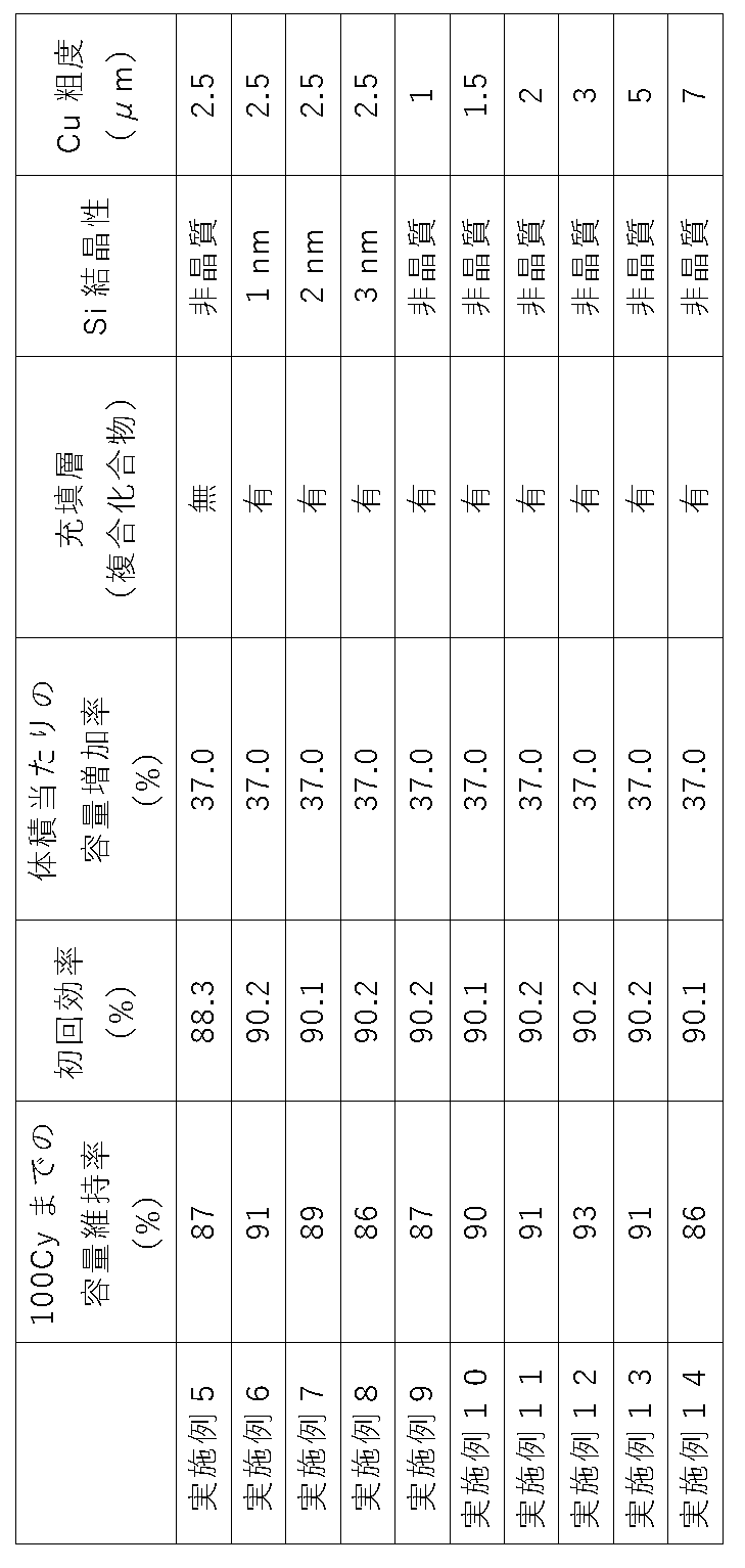
[結果]
上記表1及び表2では、比較例1に対する体積当たりの放電容量(Wh/L)の増加率を、容量増加率として示している。 [result]
Tables 1 and 2 show the rate of increase in discharge capacity per volume (Wh/L) relative to Comparative Example 1 as the rate of increase in capacity.
上記表1及び表2では、比較例1に対する体積当たりの放電容量(Wh/L)の増加率を、容量増加率として示している。 [result]
Tables 1 and 2 show the rate of increase in discharge capacity per volume (Wh/L) relative to Comparative Example 1 as the rate of increase in capacity.
表1及び表2から明らかなように、実施例1~14の負極は、電池特性(サイクル特性及び初回効率)を維持しつつ、比較例1のグラファイト負極よりも、容量を大幅に増加できたことが分かる。
As is clear from Tables 1 and 2, the negative electrodes of Examples 1 to 14 were able to significantly increase the capacity compared to the graphite negative electrode of Comparative Example 1 while maintaining the battery characteristics (cycle characteristics and initial efficiency). I understand.
一方、粉末のLiドープSiOを用いて作製した比較例2の負極は、実施例1~14の負極よりも容量が低かった。これは、比較例2の負極では、蒸着ではなく粉末を用いたために、充放電に関与しない結着剤を含んでおり、更には余分な空隙が多かったことに原因があると考えられる。
On the other hand, the negative electrode of Comparative Example 2 produced using powdered Li-doped SiO had a lower capacity than the negative electrodes of Examples 1-14. This is probably because the negative electrode of Comparative Example 2 contained a binder not involved in charge and discharge because powder was used instead of vapor deposition, and there were many extra voids.
また、比較例3の負極は、実施例1~14に比べてサイクル特性が著しく劣っていた。比較例3では、5層構造のケイ素膜に酸素を含むガスを吹き付けなかった。そのため、比較例3の負極の負極活物質層の各層は、上部に、リチウム及び酸素のうち少なくとも1種類以上を含む4価のケイ素の化合物を含有する層を有していなかった。そのため、比較例3の負極では、充放電中に負極活物質層の一部でイオン集中が起き、充放電による負極の膨張収縮により負極が劣化したものと考えられる。
In addition, the negative electrode of Comparative Example 3 was significantly inferior in cycle characteristics compared to Examples 1-14. In Comparative Example 3, no oxygen-containing gas was blown to the five-layered silicon film. Therefore, each layer of the negative electrode active material layer of the negative electrode of Comparative Example 3 did not have a layer containing a tetravalent silicon compound containing at least one of lithium and oxygen on the upper portion. Therefore, in the negative electrode of Comparative Example 3, ion concentration occurred in a part of the negative electrode active material layer during charging and discharging, and expansion and contraction of the negative electrode due to charging and discharging caused deterioration of the negative electrode.
比較例4は、実施例1~14に比べて、体積当たりの容量増加率が低かった。これは、比較例4では、ケイ素酸化物にLi挿入を行わなかったことに原因があると考えられる。
Compared to Examples 1 to 14, Comparative Example 4 had a lower capacity increase rate per volume. This is probably because in Comparative Example 4, Li was not inserted into the silicon oxide.
比較例5及び6、並びに実施例1~3は、バルク内の酸素量(酸素比率O/Si)を調整した例である。
Comparative Examples 5 and 6 and Examples 1 to 3 are examples in which the amount of oxygen in the bulk (oxygen ratio O/Si) was adjusted.
酸化ケイ素は、ケイ素と二酸化珪素から生成することから、酸素量の増減は難しい。また、比O/Siが0.7である酸化ケイ素(比較例5)は価数が制御できず、かなりケイ素の要素を残した結果となった。
Since silicon oxide is produced from silicon and silicon dioxide, it is difficult to increase or decrease the amount of oxygen. In addition, silicon oxide (Comparative Example 5) having a ratio O/Si of 0.7 could not control the valence, resulting in a large amount of silicon elements remaining.
更なる低酸素量の実現には、蒸気に水素を導入し、積極的に還元するだけでなく、成膜レートを大幅に低減させる必要がある。
In order to achieve even lower oxygen content, it is necessary not only to introduce hydrogen into the steam and actively reduce it, but also to significantly reduce the film formation rate.
比較例5の負極は、酸素比率O/Siを0.7にした結果、実施例1~3の負極よりもサイクル特性が低くなった。これは、比較例5の負極では、酸素比率O/Siを0.7にしたため、0価のSiが電解液と反応する面積が大きくなり過ぎたことに原因があると考えられる。
The negative electrode of Comparative Example 5 had lower cycle characteristics than the negative electrodes of Examples 1 to 3 as a result of setting the oxygen ratio O/Si to 0.7. This is probably because in the negative electrode of Comparative Example 5, the oxygen ratio O/Si was set to 0.7, so that the area where the zero-valent Si reacted with the electrolytic solution was too large.
一方、酸素量を増やす場合、こちらも成膜レートを落とし、蒸気流に直接酸素を吹き込んで成形したが、酸素量が多くなると、酸化ケイ素膜の調製が困難となった。
On the other hand, when the amount of oxygen was increased, the film formation rate was also lowered and oxygen was blown directly into the vapor stream for molding.
比較例6の負極は、酸素比率O/Siを1.3にした結果、実施例1~3の負極よりも初回効率が低くなった。これは、比較例6の負極では、酸素比率O/Siを1.3にしたため、負荷物質が多くなり過ぎたことに原因があると考えられる。
The negative electrode of Comparative Example 6 had a lower initial efficiency than the negative electrodes of Examples 1 to 3 as a result of setting the oxygen ratio O/Si to 1.3. This is probably because the negative electrode of Comparative Example 6 had an oxygen ratio O/Si of 1.3, which resulted in an excessive amount of load substances.
比較例7の負極は、サイクル特性が著しく低下した。これは粗化銅箔を走行させずに酸化ケイ素膜を成膜して単層膜を生成したことにより、負極の膨張及び収縮を緩和することができなくなったことが原因と考えられる。
The negative electrode of Comparative Example 7 had significantly deteriorated cycle characteristics. This is probably because the single-layer film was formed by depositing the silicon oxide film without running the roughened copper foil, which made it impossible to alleviate the expansion and contraction of the negative electrode.
実施例6~9は、ケイ素の結晶化による電池特性への影響を検討した例である。
Examples 6 to 9 are examples of examining the influence of silicon crystallization on battery characteristics.
実施例6~9の負極は、比較例2~7よりも電池特性を維持しながら、比較例1の負極よりも容量を増加させることができた。
The negative electrodes of Examples 6-9 were able to increase the capacity more than the negative electrode of Comparative Example 1 while maintaining the battery characteristics better than those of Comparative Examples 2-7.
一方で、ケイ素が非晶質であった実施例2は、ケイ素の結晶化が進んだ実施例6~9の負極よりも優れた電池特性を示すことができた。
On the other hand, Example 2, in which silicon was amorphous, exhibited better battery characteristics than the negative electrodes of Examples 6 to 9, in which silicon was highly crystallized.
表2に示した実施例9~14は、負極集電体としての粗化銅箔の表面の粗度Rzを調整することで、最も適したポイントを模索することを目的とした例である。
Examples 9 to 14 shown in Table 2 are examples aimed at finding the most suitable point by adjusting the surface roughness Rz of the surface-roughened copper foil as the negative electrode current collector.
実施例2、及び実施例9~14の結果から、粗化銅箔の表面の粗度Rzが1.5μm以上5.0μm以上である実施例2及び実施例10~13の負極は、粗度Rzが1.5μm未満である実施例9の負極、並びに粗度Rzが5.0μmを超えた実施例14よりも優れたサイクル特性を示すことができたことが分かる。これは、実施例1及び実施例10~13の負極は、粗化銅箔の表面の粗度Rzが1.5μm以上5.0μm以上であることにより、集電体の表面の粗化部により、負極活物質層を十分に保持でき、充放電での活物質の剥離をより十分に抑えることができた結果であると考えられる。
From the results of Example 2 and Examples 9 to 14, the negative electrodes of Examples 2 and 10 to 13, in which the surface roughness Rz of the surface-roughened copper foil is 1.5 μm or more and 5.0 μm or more, have a roughness It can be seen that the negative electrode of Example 9, in which Rz is less than 1.5 μm, and the negative electrode of Example 14, in which the roughness Rz exceeds 5.0 μm, exhibited better cycle characteristics. This is because the negative electrodes of Examples 1 and 10 to 13 have a roughness Rz of the surface of the roughened copper foil of 1.5 μm or more and 5.0 μm or more, and the roughened portion of the surface of the current collector , the negative electrode active material layer can be sufficiently retained, and peeling of the active material during charging and discharging can be suppressed more sufficiently.
なお、本発明は、上記実施形態に限定されるものではない。上記実施形態は例示であり、本発明の特許請求の範囲に記載された技術的思想と実質的に同一な構成を有し、同様な作用効果を奏するものは、いかなるものであっても本発明の技術的範囲に包含される。
The present invention is not limited to the above embodiments. The above-described embodiment is an example, and any device having substantially the same configuration as the technical idea described in the claims of the present invention and exhibiting the same effect is the present invention. included in the technical scope of
Claims (10)
- 表面が粗化された負極集電体と、
該負極集電体上に設けられた負極活物質層と
を有する負極であって、
前記負極活物質層は、リチウム、ケイ素、及び酸素の化合物を有する負極活物質粒子を含み、前記負極活物質粒子を構成する前記酸素と前記ケイ素との比O/Siが0.8以上1.2以下の範囲であり、
該負極活物質層は、2層以上からなる多層構造を有しており、前記負極活物質層の多層構造の各層は、上部に、リチウム及び酸素のうち少なくとも1種類以上を含む4価のケイ素の化合物を含有する層を有しているものであることを特徴とする負極。 a negative electrode current collector having a roughened surface;
A negative electrode having a negative electrode active material layer provided on the negative electrode current collector,
The negative electrode active material layer contains negative electrode active material particles containing a compound of lithium, silicon, and oxygen, and the ratio O/Si of the oxygen to the silicon constituting the negative electrode active material particles is 0.8 or more1. is in the range of 2 or less,
The negative electrode active material layer has a multilayer structure consisting of two or more layers, and each layer of the multilayer structure of the negative electrode active material layer has tetravalent silicon containing at least one of lithium and oxygen on the top. A negative electrode comprising a layer containing a compound of - 前記4価のケイ素の化合物は、SiO2及びLi4SiO4から選ばれる1種類以上を含むものであることを特徴とする請求項1に記載の負極。 2. The negative electrode according to claim 1 , wherein the compound of tetravalent silicon contains one or more selected from SiO2 and Li4SiO4 .
- 前記負極活物質層は、
前記負極活物質粒子と、
該負極活物質粒子の粒子間及び表層に充填されてなる、少なくとも炭素原子と酸素原子が化学結合しており、前記負極活物質粒子と合金化しない複合化合物と
を有するものであることを特徴とする請求項1又は2に記載の負極。 The negative electrode active material layer is
the negative electrode active material particles;
It is characterized by having a composite compound that is filled between the particles and in the surface layer of the negative electrode active material particles, in which at least carbon atoms and oxygen atoms are chemically bonded, and that does not form an alloy with the negative electrode active material particles. The negative electrode according to claim 1 or 2. - 前記複合化合物は、エーテル系溶媒とポリフェニレン化合物若しくは多環芳香族化合物との複合物の開環分解生成物、又は前記複合物がリチウムと錯体を形成した複合物の開環分解生成物であることを特徴とする請求項3に記載の負極。 The complex compound is a ring-opening decomposition product of a complex of an ether solvent and a polyphenylene compound or a polycyclic aromatic compound, or a ring-opening decomposition product of a complex in which the complex forms a complex with lithium. The negative electrode according to claim 3, characterized by:
- 少なくとも20回充放電後の前記負極活物質粒子は、Si1+~Si3+のケイ素化合物状態が最も多いものであることを特徴とする請求項1から請求項4のいずれか1項に記載の負極。 5. The negative electrode according to any one of claims 1 to 4, wherein the negative electrode active material particles after charging and discharging at least 20 times have the silicon compound state of Si 1+ to Si 3+ in the largest amount. .
- 前記負極活物質層は、前記負極活物質粒子を1次粒子として規定した場合、充放電後に該1次粒子の集合体である2次粒子を形成するものであり、該2次粒子同士は面内方向において分離した形態を持つことを特徴とする請求項1から請求項5のいずれか1項に負極。 When the negative electrode active material particles are defined as primary particles, the negative electrode active material layer forms secondary particles that are aggregates of the primary particles after charging and discharging. 6. A negative electrode according to any one of claims 1 to 5, characterized in that it has an inwardly separated form.
- 前記負極活物質粒子は、充放電前において、Cu-Kα線を用いたX線回折により得られるSi(111)結晶面に起因するピークを有し、該結晶面に対応する結晶子サイズは1.0nm以下であることを特徴とする請求項1から請求項6のいずれか1項に記載の負極。 The negative electrode active material particles have a peak due to the Si (111) crystal plane obtained by X-ray diffraction using Cu—Kα rays before charging and discharging, and the crystallite size corresponding to the crystal plane is 1. 7. The negative electrode according to any one of claims 1 to 6, wherein the thickness is 0.0 nm or less.
- 前記負極集電体は、前記表面の十点平均粗さRzが1.5μm以上5.0μm以下のものであることを特徴とする請求項1から請求項7のいずれか1項に記載の負極。 The negative electrode according to any one of claims 1 to 7, wherein the negative electrode current collector has a surface with a ten-point average roughness Rz of 1.5 µm or more and 5.0 µm or less. .
- 請求項1から請求項8のいずれか1項に記載の負極の製造方法であって、
曲率を有するキャンロール上に前記負極集電体を巻き付ける工程と、
前記キャンロール上で前記負極集電体を走行させながら、前記負極集電体上に、2層以上からなる多層構造のケイ素及び/又は一酸化ケイ素を含む膜を気相成長させる工程と、
酸素を含んだガスを前記ケイ素及び/又は一酸化ケイ素を含む膜に吹き付けて、各層の上部に二酸化ケイ素を含有する多層構造の層を形成する工程と、
前記多層構造の層にリチウムをドープして、前記負極活物質層を形成する工程と
を含むことを特徴とする負極の製造方法。 A method for manufacturing the negative electrode according to any one of claims 1 to 8,
winding the negative electrode current collector on a can roll having a curvature;
a step of vapor-phase-growing a film containing silicon and/or silicon monoxide having a multi-layer structure consisting of two or more layers on the negative electrode current collector while running the negative electrode current collector on the can roll;
A step of blowing an oxygen-containing gas onto the film containing silicon and/or silicon monoxide to form a multilayer structure layer containing silicon dioxide on top of each layer;
and doping the layer of the multilayer structure with lithium to form the negative electrode active material layer. - 前記多層構造の層を形成する工程において、前記二酸化ケイ素を含むケイ素酸化物を各層が含有する前記多層構造の層を形成し、
前記負極活物質層を形成する工程において、前記多層構造の層をリチウムを含む溶液に浸漬することによって、前記ケイ素酸化物を酸化還元法によって改質して、前記リチウム、ケイ素、及び酸素を有する化合物とするとともに、前記負極活物質粒子の粒子間及び表層に充填されてなる、少なくとも炭素原子と酸素原子が化学結合しており、前記負極活物質粒子と合金化しない複合化合物を形成することを特徴とする請求項9に記載の負極の製造方法。 In the step of forming the layers of the multilayer structure, each layer of the multilayer structure containing the silicon oxide containing the silicon dioxide is formed,
In the step of forming the negative electrode active material layer, by immersing the multilayer structure layer in a solution containing lithium, the silicon oxide is modified by an oxidation-reduction method to contain the lithium, silicon, and oxygen. In addition to forming a compound, at least a carbon atom and an oxygen atom are chemically bonded and filled between the particles and on the surface of the negative electrode active material particles to form a composite compound that does not alloy with the negative electrode active material particles. 10. A method for manufacturing a negative electrode according to claim 9.
Priority Applications (1)
| Application Number | Priority Date | Filing Date | Title |
|---|---|---|---|
| CN202280055864.6A CN117813701A (en) | 2021-08-16 | 2022-06-30 | Negative electrode and method for manufacturing negative electrode |
Applications Claiming Priority (2)
| Application Number | Priority Date | Filing Date | Title |
|---|---|---|---|
| JP2021-132227 | 2021-08-16 | ||
| JP2021132227A JP2023026832A (en) | 2021-08-16 | 2021-08-16 | Negative electrode and negative electrode manufacturing method |
Publications (1)
| Publication Number | Publication Date |
|---|---|
| WO2023021861A1 true WO2023021861A1 (en) | 2023-02-23 |
Family
ID=85240508
Family Applications (1)
| Application Number | Title | Priority Date | Filing Date |
|---|---|---|---|
| PCT/JP2022/026347 WO2023021861A1 (en) | 2021-08-16 | 2022-06-30 | Negative electrode and method for producing negative electrode |
Country Status (4)
| Country | Link |
|---|---|
| JP (1) | JP2023026832A (en) |
| CN (1) | CN117813701A (en) |
| TW (1) | TW202310474A (en) |
| WO (1) | WO2023021861A1 (en) |
Citations (19)
| Publication number | Priority date | Publication date | Assignee | Title |
|---|---|---|---|---|
| JPH06325765A (en) | 1992-07-29 | 1994-11-25 | Seiko Instr Inc | Nonaqueous electrolytic secondary battery and its manufacture |
| JP2001185127A (en) | 1999-12-24 | 2001-07-06 | Fdk Corp | Lithium secondary battery |
| JP2002042806A (en) | 2000-07-19 | 2002-02-08 | Japan Storage Battery Co Ltd | Non-aqueous electrolyte secondary battery |
| JP2005183264A (en) * | 2003-12-22 | 2005-07-07 | Nec Corp | Negative electrode material for secondary battery, its manufacturing method, and secondary battery using it |
| JP2006114454A (en) | 2004-10-18 | 2006-04-27 | Sony Corp | Battery |
| JP2006164954A (en) | 2004-11-11 | 2006-06-22 | Matsushita Electric Ind Co Ltd | Negative electrode for lithium ion secondary battery, its manufacturing method, and lithium ion secondary battery using it |
| JP2006196447A (en) * | 2004-12-16 | 2006-07-27 | Matsushita Electric Ind Co Ltd | Negative electrode for lithium ion secondary battery, its manufacturing method, and lithium ion secondary battery using it |
| JP2007207439A (en) * | 2006-01-30 | 2007-08-16 | Sony Corp | Negative electrode for secondary battery and secondary battery using the same |
| JP2007234255A (en) | 2006-02-27 | 2007-09-13 | Sanyo Electric Co Ltd | Anode for lithium secondary battery, its manufacturing method and lithium secondary battery |
| JP2008177346A (en) | 2007-01-18 | 2008-07-31 | Sanyo Electric Co Ltd | Energy storage device |
| JP2008251369A (en) | 2007-03-30 | 2008-10-16 | Matsushita Electric Ind Co Ltd | Negative electrode for lithium secondary battery, lithium secondary battery equipped with it, and manufacturing method of negative electrode for lithium secondary battery |
| JP2008282819A (en) | 2008-07-10 | 2008-11-20 | Toshiba Corp | Manufacturing method of negative electrode active material for nonaqueous electrolyte secondary battery, and negative electrode active material for nonaqueous electrolyte secondary battery provided thereby |
| JP2009070825A (en) | 2007-09-17 | 2009-04-02 | Samsung Sdi Co Ltd | Negative active material for lithium secondary battery, its manufacturing method, negative electrode for lithium secondary battery and lithium secondary battery |
| JP2009205950A (en) | 2008-02-28 | 2009-09-10 | Shin Etsu Chem Co Ltd | Negative electrode active material for nonaqueous electrolyte secondary battery, and nonaqueous electrolyte secondary battery using the same |
| JP2009212074A (en) | 2008-02-07 | 2009-09-17 | Shin Etsu Chem Co Ltd | Negative electrode material for nonaqueous electrolyte secondary battery, manufacturing method therefor, lithium ion secondary battery, and electrochemical capacitor |
| JP2015156355A (en) | 2013-08-21 | 2015-08-27 | 信越化学工業株式会社 | Negative-electrode active substance, negative electrode active substance material, negative electrode, lithium ion secondary battery, method of manufacturing negative electrode, method of manufacturing negative electrode active substance, and method of manufacturing lithium ion secondary battery |
| JP2016225199A (en) * | 2015-06-02 | 2016-12-28 | 信越化学工業株式会社 | Negative electrode active material for nonaqueous electrolyte secondary battery, negative electrode for nonaqueous electrolyte secondary battery and nonaqueous electrolyte secondary battery, and method for producing negative electrode active material particle |
| JP2017152375A (en) * | 2016-02-23 | 2017-08-31 | 信越化学工業株式会社 | Negative electrode active material, mixed negative electrode active material material, negative electrode for nonaqueous electrolyte secondary battery, negative electrode for lithium ion secondary battery, lithium ion secondary battery, method for manufacturing negative electrode active material, method for manufacturing negative electrode, and method for manufacturing lithium ion secondary battery |
| JP2020140896A (en) * | 2019-02-28 | 2020-09-03 | 積水化学工業株式会社 | Electrode for lithium ion secondary battery and lithium ion secondary battery |
-
2021
- 2021-08-16 JP JP2021132227A patent/JP2023026832A/en active Pending
-
2022
- 2022-06-30 CN CN202280055864.6A patent/CN117813701A/en active Pending
- 2022-06-30 WO PCT/JP2022/026347 patent/WO2023021861A1/en active Application Filing
- 2022-07-06 TW TW111125304A patent/TW202310474A/en unknown
Patent Citations (19)
| Publication number | Priority date | Publication date | Assignee | Title |
|---|---|---|---|---|
| JPH06325765A (en) | 1992-07-29 | 1994-11-25 | Seiko Instr Inc | Nonaqueous electrolytic secondary battery and its manufacture |
| JP2001185127A (en) | 1999-12-24 | 2001-07-06 | Fdk Corp | Lithium secondary battery |
| JP2002042806A (en) | 2000-07-19 | 2002-02-08 | Japan Storage Battery Co Ltd | Non-aqueous electrolyte secondary battery |
| JP2005183264A (en) * | 2003-12-22 | 2005-07-07 | Nec Corp | Negative electrode material for secondary battery, its manufacturing method, and secondary battery using it |
| JP2006114454A (en) | 2004-10-18 | 2006-04-27 | Sony Corp | Battery |
| JP2006164954A (en) | 2004-11-11 | 2006-06-22 | Matsushita Electric Ind Co Ltd | Negative electrode for lithium ion secondary battery, its manufacturing method, and lithium ion secondary battery using it |
| JP2006196447A (en) * | 2004-12-16 | 2006-07-27 | Matsushita Electric Ind Co Ltd | Negative electrode for lithium ion secondary battery, its manufacturing method, and lithium ion secondary battery using it |
| JP2007207439A (en) * | 2006-01-30 | 2007-08-16 | Sony Corp | Negative electrode for secondary battery and secondary battery using the same |
| JP2007234255A (en) | 2006-02-27 | 2007-09-13 | Sanyo Electric Co Ltd | Anode for lithium secondary battery, its manufacturing method and lithium secondary battery |
| JP2008177346A (en) | 2007-01-18 | 2008-07-31 | Sanyo Electric Co Ltd | Energy storage device |
| JP2008251369A (en) | 2007-03-30 | 2008-10-16 | Matsushita Electric Ind Co Ltd | Negative electrode for lithium secondary battery, lithium secondary battery equipped with it, and manufacturing method of negative electrode for lithium secondary battery |
| JP2009070825A (en) | 2007-09-17 | 2009-04-02 | Samsung Sdi Co Ltd | Negative active material for lithium secondary battery, its manufacturing method, negative electrode for lithium secondary battery and lithium secondary battery |
| JP2009212074A (en) | 2008-02-07 | 2009-09-17 | Shin Etsu Chem Co Ltd | Negative electrode material for nonaqueous electrolyte secondary battery, manufacturing method therefor, lithium ion secondary battery, and electrochemical capacitor |
| JP2009205950A (en) | 2008-02-28 | 2009-09-10 | Shin Etsu Chem Co Ltd | Negative electrode active material for nonaqueous electrolyte secondary battery, and nonaqueous electrolyte secondary battery using the same |
| JP2008282819A (en) | 2008-07-10 | 2008-11-20 | Toshiba Corp | Manufacturing method of negative electrode active material for nonaqueous electrolyte secondary battery, and negative electrode active material for nonaqueous electrolyte secondary battery provided thereby |
| JP2015156355A (en) | 2013-08-21 | 2015-08-27 | 信越化学工業株式会社 | Negative-electrode active substance, negative electrode active substance material, negative electrode, lithium ion secondary battery, method of manufacturing negative electrode, method of manufacturing negative electrode active substance, and method of manufacturing lithium ion secondary battery |
| JP2016225199A (en) * | 2015-06-02 | 2016-12-28 | 信越化学工業株式会社 | Negative electrode active material for nonaqueous electrolyte secondary battery, negative electrode for nonaqueous electrolyte secondary battery and nonaqueous electrolyte secondary battery, and method for producing negative electrode active material particle |
| JP2017152375A (en) * | 2016-02-23 | 2017-08-31 | 信越化学工業株式会社 | Negative electrode active material, mixed negative electrode active material material, negative electrode for nonaqueous electrolyte secondary battery, negative electrode for lithium ion secondary battery, lithium ion secondary battery, method for manufacturing negative electrode active material, method for manufacturing negative electrode, and method for manufacturing lithium ion secondary battery |
| JP2020140896A (en) * | 2019-02-28 | 2020-09-03 | 積水化学工業株式会社 | Electrode for lithium ion secondary battery and lithium ion secondary battery |
Non-Patent Citations (7)
| Title |
|---|
| "Newsletter ''Denchi (battery", BATTERY ASSOCIATION OF JAPAN, 1 May 2010 (2010-05-01), pages 10 |
| "The Latest Development Trends on Lithium-ion Batteries for xEV", 27 November 2020, CMC PUBLISHING, pages: 96 - 111 |
| A. HOHLT. WIEDERP. A. VAN AKENT. E. WEIRICHG. DENNINGERM. VIDALS. OSWALDC. DENEKEJ. MAYERH. FUESS, J. NON-CRYST. SOLIDS, vol. 320, 2003, pages 255 |
| HYE JIN KIMSUNGHUN CHOISEUNG JONG LEEMYUNG WON SEOJAE GOO LEEERHAN DENIZYONG JU LEEEUN KYUNG KIMJANG WOOK CHOI, NANO LETT., vol. 16, 2016, pages 282 - 288 |
| M. YAMADAM. INABAA. UEDAK. MATSUMOTOT. IWASAKIT. OHZUKU, J.ELECTROCHEM. SOC., vol. 159, 2012, pages A1630 |
| MARIKO MIYACHIHIRONORI YAMAMOTOHIDEMASA KAWAI, J. ELECTROCHEM. SOC., vol. 154, no. 4, 2007, pages A1112 - A1117 |
| V. KAPAKLIS, J. NON-CRYSTALLINE SOLIDS, vol. 354, 2008, pages 612 |
Also Published As
| Publication number | Publication date |
|---|---|
| CN117813701A (en) | 2024-04-02 |
| JP2023026832A (en) | 2023-03-01 |
| TW202310474A (en) | 2023-03-01 |
Similar Documents
| Publication | Publication Date | Title |
|---|---|---|
| US10283756B2 (en) | Negative electrode active material, method for producing a negative electrode active material, and lithium ion secondary battery | |
| CN109155407B (en) | Negative electrode active material, mixed negative electrode active material, and method for producing negative electrode active material | |
| JP7368577B2 (en) | Negative electrode and its manufacturing method | |
| JP7410259B2 (en) | Non-aqueous electrolyte secondary battery | |
| CN113659109A (en) | Negative electrode active material, mixed negative electrode active material, and method for producing negative electrode active material | |
| WO2018051710A1 (en) | Negative electrode active substance, mixed negative electrode active substance material and method for producing negative electrode active substance | |
| JP2022121582A (en) | Negative electrode for nonaqueous electrolyte secondary battery and method of producing the same | |
| WO2023021861A1 (en) | Negative electrode and method for producing negative electrode | |
| JP7175254B2 (en) | Additive for Negative Electrode of Nonaqueous Electrolyte Secondary Battery and Aqueous Negative Electrode Slurry Composition for Nonaqueous Electrolyte Secondary Battery | |
| WO2022168474A1 (en) | Negative electrode and method for producing negative electrode | |
| WO2023017689A1 (en) | Negative electrode | |
| JP7325458B2 (en) | Negative electrode active material for non-aqueous electrolyte secondary battery and method for producing negative electrode active material for non-aqueous electrolyte secondary battery | |
| WO2023135970A1 (en) | Negative electrode active material and negative electrode | |
| WO2022239676A1 (en) | Negative electrode active material and method for producing same | |
| KR20240042448A (en) | Negative electrode and method for manufacturing negative electrode | |
| WO2023008094A1 (en) | Negative electrode and method for producing same | |
| KR20240045221A (en) | negative electrode |
Legal Events
| Date | Code | Title | Description |
|---|---|---|---|
| 121 | Ep: the epo has been informed by wipo that ep was designated in this application |
Ref document number: 22858184 Country of ref document: EP Kind code of ref document: A1 |
|
| WWE | Wipo information: entry into national phase |
Ref document number: 2022858184 Country of ref document: EP |
|
| ENP | Entry into the national phase |
Ref document number: 2022858184 Country of ref document: EP Effective date: 20240318 |