WO2023021711A1 - 端末及び無線通信方法 - Google Patents
端末及び無線通信方法 Download PDFInfo
- Publication number
- WO2023021711A1 WO2023021711A1 PCT/JP2021/030692 JP2021030692W WO2023021711A1 WO 2023021711 A1 WO2023021711 A1 WO 2023021711A1 JP 2021030692 W JP2021030692 W JP 2021030692W WO 2023021711 A1 WO2023021711 A1 WO 2023021711A1
- Authority
- WO
- WIPO (PCT)
- Prior art keywords
- sps
- pdsch
- slot
- terminal
- harq
- Prior art date
- Legal status (The legal status is an assumption and is not a legal conclusion. Google has not performed a legal analysis and makes no representation as to the accuracy of the status listed.)
- Ceased
Links
Images









Classifications
-
- H—ELECTRICITY
- H04—ELECTRIC COMMUNICATION TECHNIQUE
- H04W—WIRELESS COMMUNICATION NETWORKS
- H04W72/00—Local resource management
- H04W72/04—Wireless resource allocation
-
- H—ELECTRICITY
- H04—ELECTRIC COMMUNICATION TECHNIQUE
- H04W—WIRELESS COMMUNICATION NETWORKS
- H04W72/00—Local resource management
- H04W72/12—Wireless traffic scheduling
Definitions
- the present disclosure relates to terminals and wireless communication methods.
- LTE Long Term Evolution
- FAA Future Radio Access
- 5G 5th generation mobile communication system
- 5G+ 5th generation mobile communication system
- New-RAT Radio Access Technology
- NR Radio
- Non-Patent Document 1 various wireless technologies and network architectures are being studied in order to meet the requirements of realizing a throughput of 10 Gbps or more and keeping the delay in the wireless section to 1 ms or less (for example, Non-Patent Document 1). .
- CG PUSCH Configured Grant Physical Uplink Sched Channel
- Non-Patent Document 2 CG PUSCH
- Type 1 CG PUSCH Transmission parameters for Type 1 CG PUSCH are provided by "configuredGrantConfig”, “pusch-Config”, and “rrc-ConfiguredUplinkGrant”. Activation/deactivation of Type 1 CG PUSCH depends on RRC-configuration and does not depend on Downlink Control Information (DCI).
- DCI Downlink Control Information
- Type 2 CG PUSCH Transmission parameters for Type 2 CG PUSCH are provided by "configuredGrantConfig”, “pusch-Config", and "activation DCI”. Activation and deactivation of Type 2 CG PUSCH depends on RRC-configuration and DCI. One DCI can activate one CG PUSCH and can deactivate multiple CG PUSCHs.
- Release 16 defines the configuration of SPS PDSCH (Semi-Persistent Scheduling Downlink Shared Channel) (for example, Non-Patent Document 2).
- Transmission parameters for SPS PDSCH are provided by 'sps-Config' and 'Activation DCI'. Activation and deactivation of SPS PDSCH are dependent on DCI.
- NR is considering various technologies for methods called Ultra-Reliable and Low Latency Communications (URLLC) and Industrial Internet of Things (IIoT).
- URLLC Ultra-Reliable and Low Latency Communications
- IIoT Industrial Internet of Things
- Extended Reality such as Virtual Reality (VR) and Mixed Reality (MX) was examined, and XR scenarios, requirements, Key Performance Indicators (KPIs) and Evaluation methods are being considered.
- KPIs Key Performance Indicators
- the target requirements of XR are to consider capacity, latency (delay), mobility, and energy saving aspects.
- One aspect of the present disclosure is to provide a terminal and a wireless communication method that perform CG PUSCH communication suitable for large-capacity communication.
- a terminal includes a receiving unit that receives transmission cycle setting information in an uplink signal and individual time domain resource allocation information in a plurality of uplink channels that transmit the uplink signal, and for each transmission cycle: and a control unit that allocates the plurality of uplink channels to resources based on the individual time domain resource allocation information.
- a wireless communication method receives transmission cycle setting information in an uplink signal and individual time domain resource allocation information in a plurality of uplink channels for transmitting the uplink signal, and for each transmission cycle and allocating the plurality of uplink channels to resources based on the individual time domain resource allocation information.
- a terminal includes a receiving unit that receives transmission cycle setting information in an uplink signal and individual time domain resource allocation information in a plurality of uplink channels that transmit the uplink signal, and for each transmission cycle: a control unit that determines a leading uplink channel in one slot based on the time domain resource allocation information, and determines a trailing uplink channel in the one slot to fit within a rear boundary of the one slot; have
- a wireless communication method receives transmission cycle setting information in an uplink signal and individual time domain resource allocation information in a plurality of uplink channels for transmitting the uplink signal, and for each transmission cycle , the leading uplink channel in one slot is determined based on the time domain resource allocation information, and the trailing uplink channel in the one slot is determined so as to fit within the rear boundary of the one slot.
- FIG. 4 is a diagram showing an example of PUCCH carrier switching;
- FIG. 4 is a diagram illustrating an outline of Type 1 HARQ-ACK CB;
- FIG. 4 is a diagram illustrating an outline of Type 2 HARQ-ACK CB;
- FIG. 10 is a diagram illustrating an example of generation of Type 1 HARQ-ACK CB;
- FIG. 10 is a diagram illustrating an example of generation of Type 1 HARQ-ACK CB;
- FIG. 10 is a diagram illustrating an example of generation of Type 1 HARQ-ACK CB;
- FIG. 10 is a diagram illustrating an example of determination of candidate PDSCH reception opportunities in Step A-2;
- FIG. 4 is a diagram showing an example of PUCCH carrier switching;
- FIG. 4 is a diagram illustrating an outline of Type 1 HARQ-ACK CB;
- FIG. 4 is a diagram illustrating an outline of Type 2 HARQ-ACK CB;
- FIG. 10 is a diagram illustrating an example of generation of Type
- FIG. 4 is a diagram illustrating an example of HARQ-ACK ordering in Type 1 HARQ-ACK CB of SPS PDSCH;
- FIG. 10 is a diagram illustrating an example of CG PUSCH;
- FIG. 4 is a diagram illustrating an example of SPS PDSCH;
- FIG. 10 is a diagram illustrating a setting example of TDRA;
- FIG. 10 is a diagram showing an example of multiple SLIVs in the TDRA table;
- FIG. 10 is a diagram illustrating an example of Alt.1-1;
- FIG. 10 is a diagram illustrating an example of Alt.1-2A;
- FIG. 10 is a diagram illustrating an example of Alt.1-2B-1;
- FIG. 10 is a diagram illustrating an example of Alt.1-2B-2;
- URLLC will consider enhancements to terminal feedback for Hybrid Automatic Repeat request-Acknowledgment (HARQ-ACK).
- HARQ-ACK is an example of information related to acknowledgment (eg, acknowledgment) for data received by the terminal.
- HARQ-ACK is an example of information related to acknowledgment (eg, acknowledgment) for data received by the terminal.
- PUCCH carrier switching may be called by another name such as carrier switching for control information transmission.
- PUCCH carrier switching is a technique applied when a base station communicates through multiple cells. Dual connectivity, which is an example of communication via multiple cells, and PUCCH carrier switching will be described below.
- FIG. 1 is a diagram illustrating an example of dual connectivity (DC).
- base station 10-1 may be a Master Node (MN).
- Base station 10-2 may be a secondary node (SN).
- DC bundles carriers between different base stations.
- the base station 10-1 communicates with the terminal 20 via a primary cell (Pcell) and a secondary cell (Scell).
- Pcell primary cell
- Scell secondary cell
- terminal 20 has established an RRC connection with base station 10-1.
- the uplink control information received by the Pcell of the base station 10-1 (for example, Uplink Control Information: UCI) is notified to the base station 10-2 via a backhaul link (for example, a wired or wireless link connecting the base station 10-1 and the base station 10-2), and Scell under the base station 10-2
- a backhaul link for example, a wired or wireless link connecting the base station 10-1 and the base station 10-2
- Scell under the base station 10-2 It is difficult to reflect this in the scheduling of Therefore, in the DC, in addition to the Pcell of the base station 10-1, one carrier under the control of the base station 10-2 may be set as the Primary Scell (PScell), and PUCCH transmission may be supported by the PScell.
- PScell Primary Scell
- terminal 20 transmits UCI to base station 10-2 via PScell.
- the terminal 20 sets Scell in addition to Pcell for the base station 10-1. Also, the terminal 20 sets Scell in addition to PScell for the base station 10-2.
- the terminal 20 transmits the UCI of each carrier under the control of the base station 10-1 on the PUCCH of the Pcell. Also, the terminal 20 transmits the UCI of each carrier under the control of the base station 10-2 on PUCCH of the PScell.
- a cell group (CG) under the base station 10-1 may be called a Master Cell-Group (MCG).
- a cell group under the base station 10-2 may be called a Secondary Cell-Group (SCG).
- terminal 20 may transmit PUCCH via Pcell, PScell, and/or PUCCH-Scell. Generally, it is not assumed that terminal 20 transmits PUCCH via Scell other than Pcell, PScell, and PUCCH-Scell.
- PUCCH carrier switching is being investigated as a method of reducing HARQ-ACK feedback latency in Time Division Duplex (TDD) schemes.
- FIG. 2 is a diagram showing an example of PUCCH carrier switching.
- the base station and the terminal are communicating via cell 1 and cell 2.
- FIG. 2 cell 1 is Pcell and cell 2 is Scell.
- the example of FIG. 2 also shows downlink (DL) slots and uplink (UL) slots in each cell.
- the terminal receives data (receives Physical Downlink shared Channel (PDSCH)) at the timing of S101.
- the terminal attempts to transmit HARQ-ACK for the data received in S101 at the timing of S102, but at the timing of S102, the cell 1 slot is a downlink (DL) slot. Therefore, when the terminal transmits HARQ-ACK in cell1, the transmission of HARQ-ACK is suspended until the transmission timing of PUCCH in the uplink (UL) slot (for example, the timing of S103 in FIG. 2).
- HARQ-ACK transmission latency increases.
- the PUCCH transmission timing in the uplink (UL) slot may be referred to as a PUCCH transmission opportunity.
- the slot of cell 2 is the UL slot at the timing of S102.
- the terminal can transmit HARQ-ACK for the data received in S101 at the PUCCH transmission opportunity of cell 2 at the timing of S102, the latency of HARQ-ACK transmission can be reduced.
- URLLC particularly requires low delay in the radio section. Therefore, in 3GPP, as an extension of the URLLC technique, PUCCH carrier switching, in which a terminal switches the carrier for PUCCH transmission, is under consideration.
- the "same timing" may be completely the same timing, or may be a time resource (for example, one or more symbols (a resource in time units shorter than a symbol) may be the same or overlap.
- PUCCH carrier switching means that when the terminal attempts to transmit PUCCH at a specific transmission timing of Pcell (may be PScell or PUCCH-Scell), Pcell (may be PScell or PUCCH-Scell ) is a DL slot, the terminal selects a cell that transmits PUCCH from Pcell (may be PScell or PUCCH-Scell) from the specific transmission timing Any Scell out of one or more Scells whose timing slot is the UL slot (in the case of PScells, Scells other than PScells, and in the case of PUCCH-Scells, other than PUCCH-Scells Scell).
- the specific transmission timing unit is not limited to the slot.
- the specific transmission timing may be timing in units of subframes or timing in units of symbols.
- the first method is a method in which the base station dynamically instructs the terminal of the carrier for PUCCH transmission.
- a second method is a method in which a base station semi-statically configures a carrier for transmitting PUCCH to a terminal. It should be noted that, in the following embodiments, "transmitting PUCCH” and “transmitting PUCCH” may mean transmitting uplink control information via PUCCH.
- the terminal may notify the base station of terminal capability information (UE capability) that defines information about the capability of the terminal regarding PUCCH transmission.
- UE capability terminal capability information
- switching settings for transmission of control information may be, for example, switching resources (for example, carriers or cells) used for transmission of control information. Switching resources used for transmitting control information may be referred to as "PUCCH carrier switching.” Also, as the terminal capability information of the terminal, information indicating application of dynamic PUCCH carrier switching and/or semi-static PUCCH carrier switching may be specified. .
- the configuration operation of semi-static PUCCH carrier switching may be based on the RRC that sets the PUCCH cell timing pattern for PUCCH cells to which semi-static PUCCH carrier switching is applied. Also, configured behavior of quasi-static PUCCH carrier switching may be supported between cells of different neumerologies.
- PUCCH resource configuration may be per UL BWP (Uplink Bandwidth Part) (eg, per candidate cell and per UL BWP of that candidate cell).
- UL BWP Uplink Bandwidth Part
- the K1 value (offset) from PDSCH to HARQ-ACK may be interpreted based on the neumerology of the dynamically indicated target PUCCH cell.
- the control information may be control information for scheduling PUCCH, such as Downlink control information (DCI). Numerology may also be understood as slots or Subcarrier Spacing (SCS).
- HARQ-ACK CB terminal HARQ-ACK Codebook
- Type 1 HARQ-ACK CB may also be referred to as semi-static HARQ-ACK CB.
- a Type 2 HARQ-ACK CB may be referred to as a dynamic HARQ-ACK CB.
- a terminal may be instructed by higher layer signaling, eg, RRC, whether to apply Type 1 HARQ-ACK CB or Type 2 HARQ-ACK CB.
- FIG. 3 is a diagram explaining the outline of Type 1 HARQ-ACK CB. "scheduled" shown in FIG. 3 indicates a slot scheduled by DCI, for example. CC indicates Component Carrier.
- Type 1 HARQ-ACK CB the terminal generates HARQ-ACK bits for PDSCH regardless of whether there is a scheduled slot (PDSCH). For example, the terminal may configure NACK in non-scheduled PDSCHs, as shown in the "HARQ-ACK codebook" in FIG.
- FIG. 4 is a diagram explaining the outline of Type 2 HARQ-ACK CB.
- (x, y) shown in FIG. 4 indicates a slot scheduled by DCI, for example.
- x corresponds to the C-DAI value and y corresponds to the T-DAI value.
- DAI stands for Downlink assignment index.
- DAI indicates, for example, a scheduled PDSCH allocation where HARQ-ACK is bundled with HARQ-ACK CB.
- Type 2 HARQ-ACK CB the terminal generates HARQ-ACK bits for the scheduled PDSCH.
- the terminal may set HARQ-ACK for the scheduled PDSCH as shown in the "HARQ-ACK codebook" of FIG.
- C-DAI is counted up from 1.
- C-DAI is repeated 1->2->3->0->... for a 2-bit field, for example.
- C-DAI is counted up for each DCI reception opportunity of each CC for each slot, and is counted up from the final value of the previous slot even if the slot changes.
- T-DAI indicates the final value of C-DAI for each slot.
- Type 1 HARQ-ACK CB> 5 6, and 7 are diagrams illustrating examples of generation of Type 1 HARQ-ACK CB.
- FIG. 5 it is assumed that the numerology of the serving cell and the PUCCH cell are the same.
- the set of K1 offset from PDSCH to HARQ-ACK is ⁇ 1, 2, 3, 4 ⁇ .
- the terminal may generate HARQ-ACK CB based on Step A, Step A-1, Step A-2, and Step B below.
- the terminal determines HARQ-ACK occasions for candidate PDSCH receptions. For example, the terminal determines the n+4 slot of the PUCCH cell in FIG. For example, the terminal determines the n+5 slot of the PUCCH cell in FIG.
- the terminal determines PDSCH slot windows based on the K1 set. For example, the terminal interprets the K1 set in the neumerology of the PUCCH cell to determine the PDSCH slot window shown in the dotted frame in FIG. 5 or FIG.
- the terminal determines a candidate PDSCH reception occasion in each slot for each K1. For example, the terminal determines candidate PDSCH reception opportunities in each slot, as shown in FIG .
- candidate PDSCH reception opportunities are related to the set RI (Row index) of the Time Domain Resource Allocation (TDRA) table, as described in FIG.
- TDRA Time Domain Resource Allocation
- candidate PDSCH reception opportunities in the TDRA table that overlap with the UL configured by TDD-UL-DL-ConfigurationCommon and TDD-UL-DL-ConfigDedicated are excluded.
- candidate PDSCH reception opportunities that overlap in the time domain are determined based on specific rules.
- the terminal may determine (generate) a HARQ-ACK (HARQ-ACK information bits, HARQ-ACK CB) for each element of the determined candidate PDSCH reception opportunities. For example, the terminal may generate the following Type 1 HARQ-ACK CB in the total number of HARQ-ACK information bits O ACK .
- FIG. 8 is a diagram explaining an example of determination of candidate PDSCH reception opportunities in Step A-2.
- the table shown in the upper left of FIG. 8 shows an example of TDRA.
- K0 indicates the offset between the DCI slot and the PDSCH slot.
- Start indicates the starting symbol in the slot, and
- Length indicates the length from Start (number of symbols assigned to PDSCH).
- Mapping Type relates to a mapping type that includes information about symbols that can be set as starting symbols of PDSCH within a slot.
- FIG. 8 shows the slot format.
- the last two symbols are semi-statically configured as UL.
- the candidate PDSCH reception opportunities based on RI 0-8 of TDRA shown in the upper left of FIG. 8 are as shown in the upper right of FIG. However, candidate PDSCH reception opportunities in the TDRA table that overlap with the UL are excluded.
- candidate PDSCH reception opportunities for RI2, RI3, and RI8 that overlap with UL are excluded, and the candidate PDSCH reception opportunities in a certain slot are as shown in the lower right of FIG. That is, HARQ-ACKs in RI2, RI3, and RI8 are excluded from the generated set of HARQ-ACK CBs.
- the candidate PDSCH reception opportunities are determined based on certain rules.
- the SPS HARQ-ACK CB may be regarded as the HARQ-ACK CB in the SPS PDSCH.
- the transmission cycle is set by RRC.
- the transmission timing (K1) of HARQ-ACK of SPS PDSCH is set by RRC, for example.
- SPS PDSCH for example, is activated and deactivated by DCI.
- DCI that deactivates SPS PDSCH may be referred to as deactivation DCI.
- the terminal also sends HARQ-ACK for deactivation DCI.
- HARQ-ACKs may be ordered as follows.
- FIG. 9 is a diagram explaining an example of HARQ-ACK ordering in Type 1 HARQ-ACK CB of SPS PDSCH.
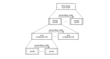
- HARQ-ACKs of SPS PDSCH are arranged in ascending order of DL slot numbers in each SPS configuration index of each serving cell index.
- the SPS PDSCH HARQ-ACKs are then ordered in ascending order of SPS configuration index at each serving cell index.
- the SPS PDSCH HARQ-ACKs are then ordered in ascending order of serving cell index.
- HARQ-ACKs may be ordered in the same way as the Type 1 HARQ-ACK CB described above.
- Type 2 HARQ-ACK CB when HARQ-ACK of SPS PDSCH reception is multiplexed with HARQ-ACK of dynamically scheduled PDSCH reception and/or HARQ-ACK of deactivation DCI, SPS PDSCH reception The HARQ-ACK(bits) is appended (following in time) the HARQ-ACK(bits) of the dynamically scheduled PDSCH reception and/or the HARQ-ACK(bits) of the deactivation DCI.
- the current SPS PDSCH and CG PUSCH may not be able to fully support XR services. For example, it may not fully support XR services with larger payload sizes.
- a terminal receives multiple SPS PDSCHs in an SPS cycle (every SPS cycle).
- a terminal appropriately processes HARQ-ACK CBs when receiving multiple SPS PDSCHs in an SPS cycle.
- CG PUSCH multiple PUSCH transmissions are defined in a CG period (grant period) (each CG period).
- CG period grant period
- the current CG PUSCH lacks flexibility and may not be able to fully support XR services.
- FIG. 10 is a diagram explaining an example of CG PUSCH.
- the parameters cg-nrofSlots and cg-nrofPUSCH-InSlot are provided to the terminal by higher layers.
- cg-nrofSlots indicates the number of consecutive slots allocated in the set CG period.
- cg-nrofPUSCH-InSlot indicates the number of consecutive PUSCH allocations within a slot.
- a CG period (a period during which CG PUSCH is transmitted, eg, 3 slots shown in FIG. 10) is repeated in the set CG period.
- the initial PUSCH allocation is based on higher layer settings based on TDRA or TS38.321 in Type 1 CG PUSCH. Alternatively, the initial PUSCH allocation is based on UL grants received on DCI for Type 2 CG PUSCH. The remaining PUSCH allocations have the same length and mapping type as the first PUSCH. Each PUSCH is added after the previous PUSCH without gaps.
- the current CG PUSCH lacks flexibility.
- PUSCH cannot be transmitted in gaps between slots (for example, double-headed arrow A1 shown in FIG. 10). Therefore, it may not be fully compatible with XR services.
- a terminal flexibly deals with gaps between slots in CG PUSCH. Also, the terminal flexibly deals with gaps between slots in the SPS PDSCH.
- a terminal may receive multiple SPS PDSCHs in the SPS cycle of the configured SPS PDSCH.
- a terminal may receive one or more SPS PDSCHs in the slots assigned in the SPS period.
- the slots allocated in the SPS period may be consecutive.
- FIG. 11 is a diagram explaining an example of the SPS PDSCH.
- the parameters sps-nrofSlots and sps-nrofPDSCH-InSlot may be provided to the terminal by higher layers, such as RRC.
- the parameters sps-nrofSlots and sps-nrofPDSCH-InSlot may be included in the SPS-Config information element of RRC, for example.
- sps-nrofSlots may indicate the number of consecutive slots for SPS PDSCH transmission allocated in the set SPS period.
- sps-nrofPDSCH-InSlot may indicate the number of consecutive SPS PDSCH allocations in a slot.
- the SPS period (period for receiving SPS PDSCH, eg, 3 slots shown in FIG. 11) is repeated in the set SPS period.
- multiple SPS PDSCH receptions in (every) SPS cycle may be referred to as multiple PDSCHs.
- Multiple CG PUSCH transmissions in (every) CG period may be referred to as multiple PUSCHs. Both or one of multiple PDSCHs and multiple PUSCHs may be applied to the terminal.
- Multiple PDSCHs may be supported for one SPS periodicity.
- Multiple PUSCHs may be supported for one CG periodicity.
- Separate (different) TDRAs may be indicated or set in each of a plurality of SPS PDSCHs in one SPS period.
- a separate TDRA may be indicated or set for each of a plurality of CG PUSCHs in one CG cycle.
- Type 1 CG PUSCH In the case of Type 1 CG PUSCH, multiple TDRAs may be set for one multiple PUSCHs setting.
- FIG. 12 is a diagram explaining a setting example of TDRA.
- multiple TDRAs may be set based on the RRC parameters for setting one multiple PUSCHs, as shown in the underlined part of FIG.
- Type 2 CG PUSCH multiple TDRAs may be indicated by activation DCI of CG PUSCH for one multiple PUSCH setting.
- SPS PDSCH multiple TDRAs may be indicated by activation DCI of SPS PDSCH for one multiple PDSCH configuration.
- One TDRA field of the activation DCI may indicate the RI of the TDRA table with at least one RI, which is a TDRA table with multiple Strat and length Indicator Values (SLIVs).
- SIVs Strat and length Indicator Values
- FIG. 13 is a diagram showing an example of multiple SLIVs in the TDRA table.
- mapping type is omitted.
- one RI in the TDRA table may have multiple SLIVs.
- the terminal may refer to the TDRA table based on the RI notified by the activation DCI and determine (acquire) the SLIV of multiple CG PUSCHs of multiple PUSCHs.
- the terminal may refer to the TDRA table based on the RI notified by the activation DCI and determine the SLIV of multiple SPS PDSCHs of multiple PDSCHs.
- Alt.1 there is no effect (change) on activation DCI of CG PUSCH. Also, Alt.1 can reuse the TDRA table (enhanced in Rel-17) for multiple PUSCHs scheduling.
- Alt.1 has no effect on SPS PDSCH activation DCI.
- Alt.1 also allows reuse of the TDRA table (enhanced in Rel-17) for multiple PDSCHs scheduling.
- a plurality of TDRA fields may be included in activation DCI of CG PUSCH.
- Each of the multiple TDRA fields may indicate the RI of a TDRA table with only one SLIV in each row.
- one SLVI indicated by each RI of multiple TDRA fields may indicate the SLIV of each CG PUSCH in the CG period.
- the SPS PDSCH activation DCI may contain multiple TDRA fields. Each of the multiple TDRA fields may indicate the RI of a TDRA table with only one SLIV in each row.
- one SLVI indicated by each RI of multiple TDRA fields may indicate the SLIV of each SPS PDSCH in the SPS period.
- the TDRA table for single multiple PUSCHs scheduling can be reused.
- the TDRA table for single multiple PDSCHs scheduling can be reused.
- TDRA may be indicated and/or set for the first SPS PDSCH in one SPS period.
- TDRA may be indicated and/or set for the first CG PUSCH in one CG period.
- the TDRA of subsequent SPS PDSCHs may be determined based on the TDRA of the first SPS PDSCH and the number of SPS PDSCHs in one cycle.
- the TDRA of subsequent CG PUSCHs may be determined based on the TDRA of the first CG PUSCH and the number of CG PUSCHs in one period.
- TDRAs of multiple PDSCHs may be allocated on a slot basis.
- a TDRA of multiple PUSCHs may be allocated on a slot basis.
- the SPS PDSCH resource allocation may be the same in each slot.
- the number of SPS PDSCH slots in one period may be indicated by activation DCI (if present) or may be configured by RRC.
- the number of SPS PDSCHs may be configured for each configured SPS or commonly for all configured SPSs.
- the CG PUSCH resource allocation may be the same in each slot.
- the number of CG PUSCH slots in one period may be indicated by activation DCI (if present) or may be set by RRC.
- the number of CG PUSCHs may be configured for each configured CG or commonly for all configured CGs.
- One SPS PDSCH may be allocated in one slot.
- One CG PUSCH may be assigned in one slot.
- FIG. 14 is a diagram explaining an example of Alt.1-1.
- the terminal receives three SPS PDSCHs in the set SPS cycle.
- the terminal receives one SPS PDSCH in one slot.
- TDRA may be indicated or set for the SPS PDSCH in the first slot (eg, the leftmost slot in FIG. 14).
- the TDRA in the SPS PDSCH of the first slot may be applied to the SPS PDSCH of the remaining slots.
- Multiple SPS PDSCHs may be allocated in one slot.
- Multiple CG PUSCHs may be allocated in one slot.
- the number of multiple SPS PDSCHs in one slot may be explicitly indicated and/or configured.
- the number of multiple CG PUSCHs in one slot may be explicitly indicated and/or set.
- each SPS PDSCH may be the same as the length of the first SPS PDSCH.
- the length of each CG PUSCH may be the same as the length of the first CG PUSCH.
- FIG. 15 is a diagram explaining an example of Alt.1-2A.
- the number of consecutive slots for SPS PDSCH transmission allocated in the set SPS cycle is three.
- a terminal receives two SPS PDSCHs in each slot.
- the number of multiple SPS PDSCHs in one slot may be explicitly indicated and/or set.
- the number “2” of multiple SPS PDSCHs in one slot shown in FIG. 15 may be explicitly indicated and/or set by higher layer parameters such as DCI or RRC.
- the length of the SPS PDSCH shown in FIG. 15 may be the same as the length of the first SPS PDSCH.
- the number of SPS PDSCHs in one slot may be implicitly determined as the maximum allowed number of PDSCHs in a slot, assuming that the length of the PDSCH is equal to the length of the first PDSCH.
- the number of multiple CG PUSCHs in one slot may be implicitly determined as the maximum allowed number of PUSCHs in a slot, assuming that the PUSCH length is equal to the initial PUSCH length.
- the last SPS PDSCH in a slot may be shorter than the length of the first SPS PDSCH.
- the last CG PUSCH in a slot may be shorter than the length of the first CG PUSCH.
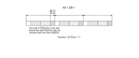
- FIG. 16 is a diagram explaining an example of Alt.1-2B-1.
- the number of consecutive slots for SPS PDSCH transmission allocated in the set SPS cycle is three.
- the terminal determines the maximum number of SPS PDSCHs allowed in the time domain in one slot based on the length of the SPS PDSCH and the length of the slot, May be implicitly determined.
- the maximum allowed number in a slot of SPS PDSCH is three.
- the length of the first SPS PDSCH in one slot and the length of the second SPS PDSCH are the same, but the length of the last SPS PDSCH in one slot may be shorter than the length of the other SPS PDSCHs. .
- the terminal may allocate the first SPS PDSCH to the slot based on TDRA.
- the terminal may continuously allocate SPS PDSCHs of the same length as the first SPS PDSCH so as to fit in the slot.
- the terminal may allocate an SPS PDSCH having a length shorter than the initial SPS PDSCH in resources (symbols) in which the consecutive SPS PDSCHs of the slots do not fit (for example, double-headed arrow A11 portion shown in FIG. 16).
- the last SPS PDSCH in a slot may be longer than the length of the first SPS PDSCH.
- the last CG PUSCH in a slot may be longer than the length of the first CG PUSCH.
- FIG. 17 is a diagram explaining an example of Alt.1-2B-2.
- the number of consecutive slots for SPS PDSCH transmission allocated in the set SPS period is two.
- the terminal determines the maximum number of SPS PDSCHs allowed in the time domain in one slot based on the length of the SPS PDSCH and the length of the slot, May be implicitly determined.
- the maximum allowed number in a slot of SPS PDSCH is two.
- the length of the second SPS PDSCH in one slot (the last SPS PDSCH in one slot) may be longer than the length of other SPS PDSCHs.
- the terminal may allocate the first SPS PDSCH to the slot based on TDRA.
- the terminal may continuously allocate SPS PDSCHs of the same length as the first SPS PDSCH so as to fit in the slot.
- the terminal uses the last SPS PDSCH (in the example of FIG. 17, the second SPS PDSCH). may be longer than other SPS PDSCHs.
- the last remaining symbols shorter than the length of the first SPS PDSCH in the slot may be dropped.
- the last remaining symbols shorter than the length of the first CG PUSCH in the slot may be dropped.
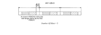
- FIG. 18 is a diagram explaining an example of Alt.1-2B-3.
- the number of consecutive slots for SPS PDSCH transmission allocated in the set SPS cycle is three.
- the terminal determines the maximum number of SPS PDSCHs allowed in the time domain in one slot based on the length of the SPS PDSCH and the length of the slot, May be implicitly determined.
- the maximum allowed number in a slot of SPS PDSCH is two.
- the terminal may drop the SPS PDSCH in resources shorter than the SPS PDSCH in one slot.
- the terminal may allocate the first SPS PDSCH to the slot based on TDRA.
- the terminal may continuously allocate SPS PDSCHs of the same length as the first SPS PDSCH so as to fit in the slot.
- the terminal does not need to drop (assign) SPS PDSCHs in resources (symbols) in which the consecutive SPS PDSCHs of the slots do not fit (for example, double-headed arrow A31 portion shown in FIG. 18).
- Multiple SPS PDSCHs may be allocated consecutively based on the TDRA in one period.
- Multiple CG PUSCHs may be allocated consecutively based on the TDRA in one period.
- multiple SPS PDSCHs may be allocated consecutively across slots like PUSCH-repetition type B.
- multiple CG PUSCHs may be allocated consecutively across slots.
- the nominal SPS PDSCH may be split into two actual PDSCHs, similar to PUSCH-repetition type B. If the CG PUSCH allocated by the TDRA spans slots, the nominal CG PUSCH may be split into two actual PUSCHs, similar to PUSCH-repetition type B.
- the number of SPS PDSCH and CG PUSCH may be counted based on Alt.2-1 or Alt.2-2 below.
- the number of SPS PDSCHs may be counted based on the nominal SPS PDSCH.
- the number of CG PUSCHs may be counted based on the nominal SPS PDSCH.
- FIG. 19 is a diagram explaining an example of Alt.2-1.
- a line A31a shown in FIG. 19 indicates a slot boundary.
- the number of SPS PDSCHs is counted based on the nominal SPS PDSCH. That is, the number of SPS PDSCHs is counted before one SPS PDSCH is divided by slots. For example, an SPS PDSCH divided at slot boundaries is counted as one.
- nominal SPS PDSCHs are allocated to resources as shown in FIG.
- the terminal decodes the nominal SPS PDSCH assigned to the resource.
- the number of SPS PDSCHs may be counted based on the actual SPS PDSCH.
- the number of CG PUSCHs may be counted based on the actual SPS PDSCH.
- FIG. 20 is a diagram explaining an example of Alt.2-2.
- a line A31b shown in FIG. 20 indicates a slot boundary.
- Alt.2-2 counts the number of SPS PDSCHs based on the actual SPS PDSCHs. That is, the number of SPS PDSCHs is counted after one SPS PDSCH is divided by slots. For example, SPS PDSCHs divided at slot boundaries are counted as two. Therefore, when the number of SPS PDSCHs in an SPS cycle is 4 and one SPS PDSCH spans slots, the actual SPS PDSCH is allocated to resources as shown in FIG. The terminal decodes the actual SPS PDSCH assigned to the resource.
- the number of SPS PDSCHs transmitted in the SPS period may be indicated by activation DCI (if present) or may be set by RRC.
- the number of SPS PDSCHs may be configured for each configured SPS or commonly for all configured SPSs.
- the number of CG PUSCHs transmitted in a CG period may be indicated by activation DCI (if present) or set by RRC.
- the number of CG PUSCHs may be set for each set CG or commonly for all set CGs.
- Parameters other than TDRA apply to multiple PDSCH, such as Frequency Domain Resource Allocation (FDRA), Modulation Coding Scheme (MCS), Redundancy Version (RV), Transmission Configuration Indication (TCI) state, or SRS resource indicator (SRI).
- FDRA Frequency Domain Resource Allocation
- MCS Modulation Coding Scheme
- RV Redundancy Version
- TCI Transmission Configuration Indication
- SRI SRS resource indicator
- FDRA Frequency Domain Resource Allocation
- MCS Modulation Coding Scheme
- RV Redundancy Version
- TCI Transmission Configuration Indication
- SRI SRS resource indicator
- the above parameters may be commonly indicated and/or commonly set for all SPS PDSCHs in one SPS cycle.
- the above parameters may be commonly indicated and/or commonly set for all CG PUSCHs in one CG cycle.
- the above parameters may be individually indicated and/or individually set for all SPS PDSCHs in one SPS period.
- the above parameters may be indicated and/or set individually for all CG PUSCHs in one CG cycle.
- rrc-ConfiguredUplinkGrant may be used for individual setting of the above parameters.
- rrc-ConfiguredUplinkGrant may be used for individual setting of the above parameters.
- separate fields for the above parameters may be included in the CG activation DCI and the SPS activation DCI.
- ⁇ Proposal 4> Actual transmission of PDSCH (reception in the terminal) may occur in all SPS PDSCHs or may be performed in some SPS PDSCHs in one SPS cycle. Actual transmission of PUSCH may be performed in all CG PUSCHs or in some CG PUSCHs in one CG period.
- the terminal may receive PDSCHs in 6 SPS PDSCHs of multiple PDSCHs shown in FIG. good too.
- the number of actual receptions in one SPS period and the number of actual transmissions in one CG period may be determined according to Alt.1 or Alt.2 below.
- the number of actual receptions in one SPS period may be determined by blind detection.
- the number of actual transmissions in one CG period may be determined by blind detection.
- the terminal may not perform blind detection on the SPS PDSCH following the certain SPS PDSCH.
- blind detection determination if the base station determines that there is no actual transmission on a CG PUSCH, the base station may not perform blind detection on the CG PUSCH following a CG PUSCH.
- the terminal determines that there is no actual reception in the second SPS PDSCH from the left end of the nine SPS PDSCHs of multiple PDSCHs shown in FIG. You don't have to perform number brand detection.
- the number of actual receptions in one SPS period may be signaled by control information included in the first SPS PDSCH in the SPS period.
- the number of actual transmissions in one CG period may be signaled by control information included in the first CG PUSCH in the CG period.
- the control information contained in the first SPS PDSCH in an SPS period may indicate that there are N actual PDSCH receptions in this SPS period.
- N may be a number less than or equal to the maximum number of SPS PDSCHs included in one SPS period.
- the terminal may not perform blind detection on the (N+1)-th SPS PDSCH included in one SPS period when N is less than the maximum number of SPS PDSCHs.
- the control information included in the first CG PUSCH in a CG period may indicate that there are N actual PUSCH transmissions in this CG period.
- N may be a number equal to or less than the maximum number of CG PUSCHs included in one CG period.
- the base station may not perform blind detection in the (N+1)-th PUSCH included in one CG period when N is less than the maximum number of CG PUSCHs.
- the terminal may blindly detect the SPS PDSCH at all SPS PDSCH reception opportunities. Note that even if the terminal determines that there is no actual reception in a certain SPS PDSCH in one SPS period, the terminal performs blind detection on the remaining SPS PDSCHs.
- Actual transmission may not occur in all CG PUSCHs of one CG cycle. For example, even though many CG PUSCH candidates are set in one slot in response to an XR service request, there may be cases where actual reception does not occur at a certain timing.
- the base station may blindly detect the CG PUSCH at all CG PUSCH reception opportunities. Note that even if the base station determines that there is no actual transmission in a certain CG PUSCH in one CG period, it blind-detects the remaining CG PUSCH.
- Proposal 5 describes HARQ-ACK feedback in one SPS period of multiple PDSCHs.
- HARQ-ACK timing ⁇ Alt.1>
- the timing of HARQ-ACK reporting may be determined separately for each SPS PDSCH. Therefore, HARQ-ACKs exist for the number of SPS PDSCHs, and a plurality of K1s may also exist.
- K1 may be indicated to the terminal by the activation DCI of each configured SPS PDSCH. Also, one K1 may be commonly applied in each SPS PDSCH that is indicated to the terminal by the activation DCI and configured.
- HARQ-ACK feedback for multiple SPS PDSCHs in one SPS period may be reported in one PUCCH.
- HARQ-ACKs of nine SPS PDSCHs shown in FIG. 16 may be reported in one PUCCH.
- the PUCCH transmission timing may be determined based on K1 indicated by the activation DCI and the first or last SPS PDSCH slot of the SPS period.
- FIG. 21 is a diagram illustrating an example of HARQ-ACK ordering in Type 1 HARQ-ACK CB of multiple PDSCHs.
- HARQ-ACKs of SPS PDSCHs in multiple PDSCHs are arranged in ascending order of starting symbols (numbers) of SPS PDSCHs in each DL slot number of each SPS configuration index in each serving cell index.
- the SPS PDSCH HARQ-ACKs are then ordered in ascending order of DL slot number at each SPS configuration index for each serving cell index.
- the SPS PDSCH HARQ-ACKs are then ordered in ascending order of SPS configuration index in each serving cell index.
- the SPS PDSCH HARQ-ACKs are then ordered in ascending order of serving cell index.
- HARQ-ACKs may be ordered in the same way as the Type 1 HARQ-ACK CB described above.
- Type 2 HARQ-ACK CB when HARQ-ACK of SPS PDSCH reception is multiplexed with HARQ-ACK of dynamically scheduled PDSCH reception and/or HARQ-ACK of deactivation DCI, SPS PDSCH reception The HARQ-ACK(bits) is appended (following in time) the HARQ-ACK(bits) of the dynamically scheduled PDSCH reception and/or the HARQ-ACK(bits) of the deactivation DCI.
- Type 1 HARQ-ACK feedback in SPS PDSCH and dynamic PDSCH of multiple PDSCHs If individual TDRA is indicated and/or set for each SPS PDSCH (for example, see Opt.1 of Proposal 2), Type 1
- the HARQ-ACK CB generation procedure may follow the generation procedure in Rel.-15 or Rel.-16. Also, the Type 1 HARQ-ACK CB generation procedure may follow the HARQ-ACK CB generation procedure for multi-PDSCH scheduling under discussion in Rel.-17.
- Opt.1 or Opt.2 may be applied.
- Multiple candidate PDSCH reception opportunities in one SLIV may be determined as follows.
- FIG. 22 is a diagram illustrating an example of candidate PDSCH reception opportunities.
- the number N of multiple candidate PDSCH reception opportunities for one SLIV may be determined by the maximum number of SPS PDSCHs in one slot. good.
- the number N of candidate PDSCH reception opportunities may be 3 if the timing of HARQ-ACK reporting is determined individually for each SPS PDSCH.
- the number of multiple candidate PDSCH reception opportunities for one SLIV is the maximum number of SPS PDSCHs in one SPS cycle may be determined by
- the number of candidate PDSCH reception opportunities may be nine.
- One candidate PDSCH reception opportunity in one SLIV may be determined as follows.
- the PDSCH slot set (PDSCH slot window) may be extended or the K1 set may be extended.
- the PDSCH slot set or K1 set may be expanded based on the maximum number of PDSCH slots in one SPS period.
- the PDSCH slot set or K1 set consists of "maximum number of PDSCH slots in one SPS period" and "maximum number of PDSCH slots for multiple PDSCH scheduling by one DCI". may be expanded based on the maximum value between
- FIG. 23 is a diagram explaining an example of an extended PDSCH slot set.
- One SPS cycle includes multiple SPS PDSCHs.
- the PDSCH slot set may be extended as indicated by dotted line frame A41a in FIG.
- a dotted line frame A41b in FIG. 23 indicates, for example, a PDSCH slot set obtained from the value of K1 of the first SPS PDSCH in one SPS cycle.
- a candidate PDSCH reception opportunity in each candidate PDSCH slot after the K1 extension may be determined based on the set of SLIVs for each row of the TDRA table.
- Opt.2-1 of Proposal 5 is the case of slot-based multiple PDSCHs in which one PDSCH is included in one slot, and HARQ-ACK for multiple SPS PDSCHs in one SPS period is 1 applied when reported on one PUCCH.
- Opt.2-1 of Proposal 5 is applied to the Alt.1-1 case of Opt.2 of Proposal 2 (see, for example, FIG. 14).
- the PDSCH slot set may be extended and each row of the TDRA table may be extended.
- Step 1 The PDSCH slot set or K1 set is extended in the same manner as Step 1 of Opt.2-1 above.
- SLIV may be extended assuming that the SLIV of the original TDRA table is the first PDSCH (SPS PDSCH) of one slot. SLIVs of PDSCHs following the first PDSCH in the same slot may be added to the TDRA table row.
- SPS PDSCH first PDSCH
- FIG. 24 is a diagram explaining an extension example of SLIV.
- the table shown in the lower left of FIG. 24 shows the original TDRA table.
- the original TDRA table contains the SILV of the first PDSCH in one slot.
- the table shown in the lower right of Fig. 24 shows the extended TDRA table.
- the extended TDRA table includes the SILV of the PDSCH following the first PDSCH in addition to the SILV of the first PDSCH in one slot.
- Candidate PDSCH reception opportunities in each candidate PDSCH slot after K1 extension may be determined based on the SLIV set for each row of the extended TDRA table.
- Opt.2-2 of Proposal 5 is the case of slot-based multiple PDSCH in which multiple PDSCHs are included in one slot, and HARQ-ACK for multiple SPS PDSCHs in one SPS period is 1 applied when reported on one PUCCH.
- Opt.2-2 of Proposal 5 is applied to the Alt.1-2 case of Opt.2 of Proposal 2 (see, for example, FIG. 15).
- SLIV may be extended in each row of the TDRA table.
- SLIV may be extended assuming that SLIV is the first PDSCH of one SPS period.
- the SLIVs of the PDSCHs following the first PDSCH in one SPS period may be added to the TDRA table rows assuming the maximum number of SPS PDSCHs in one SPS period.
- FIG. 25 is a diagram explaining an extension example of SLIV.
- the table shown in the lower left of FIG. 25 shows the original TDRA table.
- the original TDRA table contains the SILV of the first PDSCH in one slot.
- the table shown in the lower right of FIG. 25 shows the expanded TDRA table.
- the extended TDRA table includes the SILV of the first PDSCH in one SPS period as well as the SILV of the PDSCHs following the first PDSCH.
- the determination of candidate PDSCH slots and candidate PDSCH reception opportunities may follow the multiple PDSCH scheduling determination of Rel.-17.
- Opt.2-3 of Proposal 5 is applied to the case of slot-based multiple PDSCHs in which one PDSCH is included in one slot and to the case of slot-based multiple PDSCH in which one slot includes multiple PDSCHs. be.
- Opt.2-3 of Proposal 5 is applied to Alt.1 and Alt.2 of Opt.2 of Proposal 2 (see, eg, FIGS. 14-18).
- the UE capability indicating the capability of the UE may include the following information indicating the capability of the UE. Note that the information indicating the capabilities of the UE may correspond to information defining the capabilities of the UE.
- the radio communication system includes base station 10 shown in FIG.26 and terminal 20 shown in FIG.27.
- the number of base stations 10 and the number of terminals 20 are not particularly limited.
- the wireless communication system may be a wireless communication system according to New Radio (NR).
- NR New Radio
- the wireless communication system may be a wireless communication system according to a scheme called URLLC and/or IIoT.
- the wireless communication system may be a wireless communication system that conforms to a system called 5G, Beyond 5G, 5G Evolution, or 6G.
- the base station 10 may be called an NG-RAN Node, ng-eNB, eNodeB (eNB), or gNodeB (gNB).
- the terminal 20 may be called User Equipment (UE).
- the base station 10 may be regarded as a device included in the network to which the terminal 20 connects.
- the radio communication system may include Next Generation-Radio Access Network (NG-RAN).
- NG-RAN includes multiple NG-RAN Nodes, specifically gNBs (or ng-eNBs), and is connected to a 5G-compliant core network (5GC, not shown).
- 5GC 5G-compliant core network
- NG-RAN and 5GC may be simply referred to as "networks”.
- the base station 10 performs wireless communication with the terminal 20.
- the wireless communication performed complies with NR.
- At least one of the base station 10 and the terminal 20 uses Massive MIMO (Multiple-Input Multiple-Output) to generate beams (BM) with higher directivity by controlling radio signals transmitted from a plurality of antenna elements. You can respond.
- at least one of the base station 10 and the terminal 20 may support carrier aggregation (CA) that uses multiple component carriers (CC) in a bundle.
- CA carrier aggregation
- CC component carriers
- at least one of the base station 10 and the terminal 20 may support dual connectivity (DC), etc., in which communication is performed between the terminal 20 and each of the plurality of base stations 10 .
- a wireless communication system may support multiple frequency bands.
- a wireless communication system supports Frequency Ranges (FR) 1 and FR2.
- the frequency bands of each FR are, for example, as follows. ⁇ FR1: 410MHz to 7.125GHz ⁇ FR2: 24.25GHz to 52.6GHz
- FR1 Sub-Carrier Spacing (SCS) of 15 kHz, 30 kHz or 60 kHz may be used, and a bandwidth (BW) of 5 MHz to 100 MHz may be used.
- SCS Sub-Carrier Spacing
- BW bandwidth
- FR2 is, for example, a higher frequency than FR1.
- FR2 may use an SCS of 60 kHz or 120 kHz and a bandwidth (BW) of 50 MHz to 400 MHz.
- FR2 may include a 240 kHz SCS.
- the wireless communication system in this embodiment may support a frequency band higher than the frequency band of FR2.
- the wireless communication system in this embodiment can support frequency bands exceeding 52.6 GHz and up to 114.25 GHz.
- Such high frequency bands may be referred to as "FR2x.”
- Cyclic Prefix-Orthogonal Frequency Division Multiplexing CP-OFDM
- DFT-S-OFDM Discrete Fourier Transform - Spread - Orthogonal Frequency Division Multiplexing
- SCS Sub-Carrier Spacing
- DFT-S-OFDM may be applied to both uplink and downlink, or may be applied to either one.
- a time division duplex (TDD) slot configuration pattern may be set.
- slots for transmitting downlink (DL) signals, slots for transmitting uplink (UL) signals, slots in which DL signals, UL signals and guard symbols are mixed, and signals to be transmitted are flexible
- a pattern may be defined that indicates the order of two or more of the slots to be changed to .
- channel estimation of PUSCH can be performed using a demodulation reference signal (DMRS) for each slot.
- DMRS demodulation reference signal
- Such channel estimation may be called joint channel estimation. Alternatively, it may be called by another name such as cross-slot channel estimation.
- the terminal 20 may transmit the DMRS assigned to each of the multiple slots so that the base station 10 can perform joint channel estimation using DMRS.
- an enhanced function may be added to the feedback function from the terminal 20 to the base station 10.
- enhanced functionality of terminal feedback for HARQ-ACK may be added.
- the configurations of the base station 10 and the terminal 20 will be explained. It should be noted that the configurations of the base station 10 and the terminal 20 described below are examples of functions related to the present embodiment.
- the base station 10 and terminal 20 may have functions not shown. Also, the functional division and/or the name of the functional unit are not limited as long as the function executes the operation according to the present embodiment.
- FIG. 26 is a block diagram showing an example of the configuration of base station 10 according to this embodiment.
- the base station 10 includes a transmitter 101, a receiver 102, and a controller 103, for example.
- the base station 10 wirelessly communicates with the terminal 20 (see FIG. 27).
- the transmission section 101 transmits a downlink (DL) signal to the terminal 20 .
- the transmitter 101 transmits a DL signal under the control of the controller 103 .
- a DL signal may include, for example, a downlink data signal and control information (eg, Downlink Control Information (DCI)).
- DCI Downlink Control Information
- the DL signal may include information (for example, UL grant) indicating scheduling regarding signal transmission of the terminal 20 .
- the DL signal may include higher layer control information (for example, Radio Resource Control (RRC) control information).
- RRC Radio Resource Control
- the DL signal may include a reference signal.
- Channels used for transmitting DL signals include, for example, data channels and control channels.
- the data channel may include a PDSCH (Physical Downlink Shared Channel)
- the control channel may include a PDCCH (Physical Downlink Control Channel).
- the base station 10 transmits control information to the terminal 20 using the PDCCH, and transmits downlink data signals using the PDSCH.
- reference signals included in DL signals include demodulation reference signals (DMRS), phase tracking reference signals (PTRS), channel state information-reference signals (CSI-RS), sounding reference signals (SRS ), and Positioning Reference Signal (PRS) for position information.
- DMRS demodulation reference signals
- PTRS phase tracking reference signals
- CSI-RS channel state information-reference signals
- SRS sounding reference signals
- PRS Positioning Reference Signal
- reference signals such as DMRS and PTRS are used for demodulation of downlink data signals and transmitted using PDSCH.
- the receiving unit 102 receives an uplink (UL) signal transmitted from the terminal 20 .
- the receiver 102 receives UL signals under the control of the controller 103 .
- the control unit 103 controls the communication operation of the base station 10, including the transmission processing of the transmission unit 101 and the reception processing of the reception unit 102.
- control unit 103 acquires information such as data and control information from the upper layer and outputs it to the transmission unit 101 . Also, the control unit 103 outputs the data and control information received from the receiving unit 102 to the upper layer.
- control unit 103 based on the signal received from the terminal 20 (e.g., data and control information, etc.) and / or data and control information obtained from the upper layer, resource (or channel) used for transmission and reception of the DL signal and/or allocates resources used for transmission and reception of UL signals. Information about the allocated resources may be included in control information to be transmitted to the terminal 20 .
- the control unit 103 sets PUCCH resources as an example of allocation of resources used for transmission and reception of UL signals.
- Information related to PUCCH configuration such as the PUCCH cell timing pattern may be notified to the terminal 20 by RRC.
- FIG. 27 is a block diagram showing an example of the configuration of terminal 20 according to this embodiment.
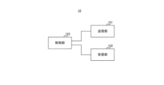
- Terminal 20 includes, for example, receiver 201 , transmitter 202 , and controller 203 .
- the terminal 20 communicates with the base station 10 by radio, for example.
- the receiving unit 201 receives the DL signal transmitted from the base station 10. For example, the receiver 201 receives a DL signal under the control of the controller 203 .
- the transmission unit 202 transmits the UL signal to the base station 10.
- the transmitter 202 transmits UL signals under the control of the controller 203 .
- the UL signal may include, for example, an uplink data signal and control information (eg, UCI).
- control information eg, UCI
- information about the processing capability of terminal 20 eg, UE capability
- the UL signal may include a reference signal.
- Channels used to transmit UL signals include, for example, data channels and control channels.
- the data channel includes PUSCH (Physical Uplink Shared Channel)
- the control channel includes PUCCH (Physical Uplink Control Channel).
- the terminal 20 receives control information from the base station 10 using PUCCH, and transmits uplink data signals using PUSCH.
- the reference signal included in the UL signal may include at least one of DMRS, PTRS, CSI-RS, SRS, and PRS, for example.
- reference signals such as DMRS and PTRS are used for demodulation of uplink data signals and transmitted using an uplink channel (eg, PUSCH).
- the control unit 203 controls communication operations of the terminal 20, including reception processing in the reception unit 201 and transmission processing in the transmission unit 202.
- control unit 203 acquires information such as data and control information from the upper layer and outputs it to the transmission unit 202 . Also, the control unit 203 outputs, for example, the data and control information received from the receiving unit 201 to an upper layer.
- control unit 203 controls transmission of information to be fed back to the base station 10 .
- Information fed back to the base station 10 may include, for example, HARQ-ACK, channel state information (CSI), or scheduling request (SR). good.
- Information to be fed back to the base station 10 may be included in the UCI.
- UCI is transmitted on PUCCH resources.
- the control unit 203 configures PUCCH resources based on configuration information received from the base station 10 (for example, configuration information such as the PUCCH cell timing pattern notified by RRC and/or DCI).
- Control section 203 determines PUCCH resources to be used for transmitting information to be fed back to base station 10 .
- transmission section 202 transmits information to be fed back to base station 10 on PUCCH resources determined by control section 203 .
- the channels used for DL signal transmission and the channels used for UL signal transmission are not limited to the above examples.
- the channel used for DL signal transmission and the channel used for UL signal transmission may include RACH (Random Access Channel) and PBCH (Physical Broadcast Channel).
- RACH may be used, for example, to transmit Downlink Control Information (DCI) containing Random Access Radio Network Temporary Identifier (RA-RNTI).
- DCI Downlink Control Information
- RA-RNTI Random Access Radio Network Temporary Identifier
- the control unit 203 may set the reception cycle of the DL signal based on the cycle setting information.
- Receiving section 201 may receive a DL signal using a plurality of SPS PDSCHs in each set reception cycle.
- the period setting information may be, for example, RRC parameters.
- the receiving section 201 may receive DL signals using multiple SPS PDSCHs in multiple consecutive slots. For example, as shown in FIG. 14, receiving section 201 may receive DL signals using one SPS PDSCH included in each of a plurality of slots. Receiving section 201 may receive DL signals using a plurality of SPS PDSCHs included in each of a plurality of slots, as shown in FIGS. 15 to 18, for example.
- the terminal 20 can perform SPS PDSCH communication suitable for large-capacity communication.
- the receiving section 201 may receive transmission cycle setting information in the UL signal and individual TDRAs in a plurality of CG PUSCHs that transmit the UL signal.
- Control section 203 may allocate CG PUSCH to resources based on individual TDRAs for each transmission cycle of the received configuration information.
- the configuration information may be, for example, RRC parameters.
- the receiving section 201 may receive the TDRA using, for example, higher layer signaling such as RRC signaling.
- RRC signaling may also be referred to as RRC messages or RRC information elements.
- the terminal 20 can perform CG PUSCH communication suitable for large-capacity communication.
- Control section 203 determines the leading CG PUSCH in one slot based on TDRA for each transmission cycle of the received configuration information, and adjusts the trailing CG PUSCH in one slot to fit within the rear boundary of one slot. may decide. For example, as shown in FIGS. 16 and 17, control section 203 determines the leading CG PUSCH in one slot based on TDRA, and places the trailing CG PUSCH in one slot at the rear boundary of one slot. You can decide to fit. Control section 203 may continuously allocate a plurality of CG PUSCHs to resources in one slot.
- the terminal 20 can perform CG PUSCH communication suitable for large-capacity communication.
- the receiving section 201 may receive the DL signal using a plurality of SPS PDSCHs at each set reception cycle, and the transmitting section 202 may transmit a DL signal response signal. Transmitting section 202 may transmit the response signal using one PUCCH.
- the response signal may be, for example, HARQ-ACK.
- the receiving unit 201 and the transmitting unit 202 may be called a communication unit.
- the control unit 203 may determine the number of candidate reception opportunities for multiple SPS PDSCHs based on the maximum number of SPS PDSCHs in one slot. Control section 203 may determine the number of candidate reception opportunities for multiple SPS PDSCHs based on the maximum number of multiple SPS PDSCHs in each reception cycle. Control section 203 may determine a slot set of multiple SPS PDSCHs to which response signals are to be transmitted, based on the maximum number of multiple SPS PDSCHs in each reception cycle.
- terminal 20 can appropriately report HARQ-ACK of SPS PDSCH suitable for large-capacity communication.
- each functional block may be implemented using one device that is physically or logically coupled, or directly or indirectly using two or more devices that are physically or logically separated (e.g. , wired, wireless, etc.) and may be implemented using these multiple devices.
- a functional block may be implemented by combining software in the one device or the plurality of devices.
- Functions include judging, determining, determining, calculating, calculating, processing, deriving, investigating, searching, checking, receiving, transmitting, outputting, accessing, resolving, selecting, choosing, establishing, comparing, assuming, expecting, assuming, Broadcasting, notifying, communicating, forwarding, configuring, reconfiguring, allocating, mapping, assigning, etc. can't
- a functional block (component) that makes transmission work is called a transmitting unit or transmitter.
- the implementation method is not particularly limited.
- a base station, a terminal, etc. may function as a computer that performs processing of the wireless communication method of the present disclosure.
- FIG. 28 is a diagram illustrating an example of hardware configurations of a base station and a terminal according to an embodiment of the present disclosure;
- the base station 10 and terminal 20 described above may be physically configured as a computer device including a processor 1001, a memory 1002, a storage 1003, a communication device 1004, an input device 1005, an output device 1006, a bus 1007, and the like.
- the term "apparatus” can be read as a circuit, device, unit, or the like.
- the hardware configuration of the base station 10 and terminal 20 may be configured to include one or more of each device shown in the figure, or may be configured without some devices.
- Each function of the base station 10 and the terminal 20 is performed by the processor 1001 by loading predetermined software (program) onto hardware such as the processor 1001 and the memory 1002, and the processor 1001 performs calculations and controls communication by the communication device 1004. , and controlling at least one of reading and writing of data in the memory 1002 and the storage 1003 .
- the processor 1001 for example, operates an operating system and controls the entire computer.
- the processor 1001 may be configured by a central processing unit (CPU) including an interface with peripheral devices, a control device, an arithmetic device, registers, and the like.
- CPU central processing unit
- the control unit 103 and the control unit 203 described above may be implemented by the processor 1001 .
- the processor 1001 reads programs (program codes), software modules, data, etc. from at least one of the storage 1003 and the communication device 1004 to the memory 1002, and executes various processes according to them.
- programs program codes
- software modules software modules
- data etc.
- the control unit 203 of the terminal 20 may be implemented by a control program stored in the memory 1002 and running on the processor 1001, and other functional blocks may be similarly implemented.
- FIG. Processor 1001 may be implemented by one or more chips.
- the program may be transmitted from a network via an electric communication line.
- the memory 1002 is a computer-readable recording medium, and is composed of at least one of, for example, ROM (Read Only Memory), EPROM (Erasable Programmable ROM), EEPROM (Electrically Erasable Programmable ROM), and RAM (Random Access Memory). may be
- ROM Read Only Memory
- EPROM Erasable Programmable ROM
- EEPROM Electrical Erasable Programmable ROM
- RAM Random Access Memory
- the memory 1002 may also be called a register, cache, main memory (main storage device), or the like.
- the memory 1002 can store executable programs (program code), software modules, etc. for implementing a wireless communication method according to an embodiment of the present disclosure.
- the storage 1003 is a computer-readable recording medium, for example, an optical disk such as a CD-ROM (Compact Disc ROM), a hard disk drive, a flexible disk, a magneto-optical disk (for example, a compact disk, a digital versatile disk, a Blu-ray disk), smart card, flash memory (eg, card, stick, key drive), floppy disk, magnetic strip, and/or the like.
- Storage 1003 may also be called an auxiliary storage device.
- the storage medium described above may be, for example, a database, server, or other suitable medium including at least one of memory 1002 and storage 1003 .
- the communication device 1004 is hardware (transmitting/receiving device) for communicating between computers via at least one of a wired network and a wireless network, and is also called a network device, a network controller, a network card, a communication module, or the like.
- the communication device 1004 includes a high-frequency switch, a duplexer, a filter, a frequency synthesizer, and the like, for example, to realize at least one of frequency division duplex (FDD) and time division duplex (TDD).
- FDD frequency division duplex
- TDD time division duplex
- the transmitting unit 101 , the receiving unit 102 , the receiving unit 201 , the transmitting unit 202 and the like described above may be implemented by the communication device 1004 .
- the input device 1005 is an input device (for example, keyboard, mouse, microphone, switch, button, sensor, etc.) that receives input from the outside.
- the output device 1006 is an output device (eg, display, speaker, LED lamp, etc.) that outputs to the outside. Note that the input device 1005 and the output device 1006 may be integrated (for example, a touch panel).
- Each device such as the processor 1001 and the memory 1002 is connected by a bus 1007 for communicating information.
- the bus 1007 may be configured using a single bus, or may be configured using different buses between devices.
- the base station 10 and the terminal 20 include hardware such as microprocessors, digital signal processors (DSPs), ASICs (Application Specific Integrated Circuits), PLDs (Programmable Logic Devices), and FPGAs (Field Programmable Gate Arrays). , and part or all of each functional block may be implemented by the hardware.
- processor 1001 may be implemented using at least one of these pieces of hardware.
- Notification of information is not limited to the embodiments described in the present disclosure, and may be performed using other methods.
- notification of information includes physical layer signaling (e.g., DCI (Downlink Control Information), UCI (Uplink Control Information)), higher layer signaling (e.g., RRC (Radio Resource Control) signaling, MAC (Medium Access Control) signaling, It may be implemented by broadcast information (MIB (Master Information Block), SIB (System Information Block)), other signals, or a combination thereof.
- RRC signaling may also be called an RRC message, and may be, for example, an RRC connection setup message, an RRC connection reconfiguration message, or the like.
- Embodiments described in the present disclosure are LTE (Long Term Evolution), LTE-A (LTE-Advanced), SUPER 3G, IMT-Advanced, 4G (4th generation mobile communication system), 5G (5th generation mobile communication system) , FRA (Future Radio Access), NR (new Radio), W-CDMA (registered trademark), GSM (registered trademark), CDMA2000, UMB (Ultra Mobile Broadband), IEEE 802.11 (Wi-Fi (registered trademark)) , IEEE 802.16 (WiMAX®), IEEE 802.20, UWB (Ultra-WideBand), Bluetooth®, other suitable systems and next generations based on these It may be applied to at least one of the systems. Also, a plurality of systems may be applied in combination (for example, a combination of at least one of LTE and LTE-A and 5G, etc.).
- various operations performed for communication with a terminal may be performed by the base station and other network nodes other than the base station (e.g. MME or S-GW, etc. (including but not limited to).
- MME or S-GW network nodes other than the base station
- the case where there is one network node other than the base station is exemplified above, it may be a combination of a plurality of other network nodes (for example, MME and S-GW).
- ⁇ Direction of input/output> Information and the like can be output from a higher layer (or a lower layer) to a lower layer (or a higher layer). It may be input and output via multiple network nodes.
- Input/output information and the like may be stored in a specific location (for example, memory), or may be managed using a management table. Input/output information and the like can be overwritten, updated, or appended. The output information and the like may be deleted. The entered information and the like may be transmitted to another device.
- the determination may be made by a value represented by one bit (0 or 1), by a true/false value (Boolean: true or false), or by numerical comparison (for example, a predetermined value).
- notification of predetermined information is not limited to being performed explicitly, but may be performed implicitly (for example, not notifying the predetermined information). good too.
- Software whether referred to as software, firmware, middleware, microcode, hardware description language or otherwise, includes instructions, instruction sets, code, code segments, program code, programs, subprograms, and software modules. , applications, software applications, software packages, routines, subroutines, objects, executables, threads of execution, procedures, functions, and the like.
- software, instructions, information, etc. may be transmitted and received via a transmission medium.
- the software may use wired technology (coaxial cable, fiber optic cable, twisted pair, Digital Subscriber Line (DSL), etc.) and/or wireless technology (infrared, microwave, etc.) to access websites, Wired and/or wireless technologies are included within the definition of transmission medium when sent from a server or other remote source.
- wired technology coaxial cable, fiber optic cable, twisted pair, Digital Subscriber Line (DSL), etc.
- wireless technology infrared, microwave, etc.
- Information, signals, etc. described in this disclosure may be represented using any of a variety of different technologies.
- data, instructions, commands, information, signals, bits, symbols, chips, etc. may refer to voltages, currents, electromagnetic waves, magnetic fields or magnetic particles, light fields or photons, or any of these. may be represented by a combination of
- the channel and/or symbols may be signaling.
- a signal may also be a message.
- a component carrier may also be referred to as a carrier frequency, cell, frequency carrier, or the like.
- ⁇ Name of parameter and channel> the information, parameters, etc. described in the present disclosure may be expressed using absolute values, may be expressed using relative values from a predetermined value, or may be expressed using other corresponding information. may be represented. For example, radio resources may be indexed.
- Base station In the present disclosure, “base station (BS)”, “radio base station”, “fixed station”, “NodeB”, “eNodeB (eNB)”, “gNodeB (gNB)”, “"accesspoint”,”transmissionpoint”,”receptionpoint”,”transmission/receptionpoint”,”cell”,”sector”,”cellgroup”,” Terms such as “carrier”, “component carrier” may be used interchangeably.
- a base station may also be referred to by terms such as macrocell, small cell, femtocell, picocell, and the like.
- a base station can accommodate one or more (eg, three) cells.
- the overall coverage area of the base station can be partitioned into multiple smaller areas, each smaller area being associated with a base station subsystem (e.g., an indoor small base station (RRH:
- RRH indoor small base station
- the term "cell” or “sector” refers to part or all of the coverage area of at least one of the base stations and base station subsystems serving communication services in this coverage.
- MS Mobile Station
- UE User Equipment
- a mobile station is defined by those skilled in the art as a subscriber station, mobile unit, subscriber unit, wireless unit, remote unit, mobile device, wireless device, wireless communication device, remote device, mobile subscriber station, access terminal, mobile terminal, wireless It may also be called a terminal, remote terminal, handset, user agent, mobile client, client, or some other suitable term.
- At least one of a base station and a mobile station may be called a transmitter, a receiver, a communication device, and the like. At least one of the base station and the mobile station may be a device mounted on a mobile object, the mobile object itself, or the like.
- the mobile object may be a vehicle (e.g., car, airplane, etc.), an unmanned mobile object (e.g., drone, self-driving car, etc.), or a robot (manned or unmanned ).
- at least one of the base station and the mobile station includes devices that do not necessarily move during communication operations.
- at least one of the base station and the mobile station may be an IoT (Internet of Things) device such as a sensor.
- IoT Internet of Things
- the base station in the present disclosure may be read as a terminal.
- the terminal 20 may have the functions of the base station 10 described above.
- words such as "up” and “down” may be replaced with words corresponding to inter-terminal communication (for example, "side").
- uplink channels, downlink channels, etc. may be read as side channels.
- a terminal in the present disclosure may be read as a base station.
- the base station 10 may have the functions of the terminal 20 described above.
- determining may encompass a wide variety of actions.
- “Judgement”, “determining” are, for example, judging, calculating, computing, processing, deriving, investigating, looking up, searching, inquiring (eg, lookup in a table, database, or other data structure), ascertaining as “judged” or “determined”, and the like.
- "judgment” and “decision” are used for receiving (e.g., receiving information), transmitting (e.g., transmitting information), input, output, access (accessing) (for example, accessing data in memory) may include deeming that something has been "determined” or “decided”.
- judgment and “decision” are considered to be “judgment” and “decision” by resolving, selecting, choosing, establishing, comparing, etc. can contain.
- judgment and “decision” may include considering that some action is “judgment” and “decision”.
- judgment (decision) may be read as “assuming”, “expecting”, “considering”, or the like.
- connection means any direct or indirect connection or connection between two or more elements, It can include the presence of one or more intermediate elements between two elements being “connected” or “coupled.” Couplings or connections between elements may be physical, logical, or a combination thereof. For example, “connection” may be read as "access”.
- two elements are defined using at least one of one or more wires, cables, and printed electrical connections and, as some non-limiting and non-exhaustive examples, in the radio frequency domain. , electromagnetic energy having wavelengths in the microwave and optical (both visible and invisible) regions, and the like.
- the reference signal may be abbreviated as RS (Reference Signal), or may be referred to as Pilot according to the applicable standard.
- a radio frame may consist of one or more frames in the time domain. Each frame or frames in the time domain may be referred to as a subframe. A subframe may also consist of one or more slots in the time domain. A subframe may be a fixed time length (eg, 1 ms) independent of numerology.
- a numerology may be a communication parameter that applies to the transmission and/or reception of a signal or channel. Numerology, for example, subcarrier spacing (SCS), bandwidth, symbol length, cyclic prefix length, transmission time interval (TTI), number of symbols per TTI, radio frame structure, transmission and reception specific filtering operations performed by the receiver in the frequency domain, specific windowing operations performed by the transceiver in the time domain, and/or the like.
- SCS subcarrier spacing
- TTI transmission time interval
- number of symbols per TTI radio frame structure
- transmission and reception specific filtering operations performed by the receiver in the frequency domain specific windowing operations performed by the transceiver in the time domain, and/or the like.
- a slot may consist of one or more symbols (OFDM (Orthogonal Frequency Division Multiplexing) symbol, SC-FDMA (Single Carrier Frequency Division Multiple Access) symbol, etc.) in the time domain.
- a slot may be a unit of time based on numerology.
- a slot may contain multiple mini-slots. Each minislot may consist of one or more symbols in the time domain. A minislot may also be referred to as a subslot. A minislot may consist of fewer symbols than a slot.
- PDSCH (or PUSCH) transmitted in time units larger than minislots may be referred to as PDSCH (or PUSCH) mapping type A.
- PDSCH (or PUSCH) transmitted using minislots may be referred to as PDSCH (or PUSCH) mapping type B.
- Radio frames, subframes, slots, minislots and symbols all represent time units when transmitting signals. Radio frames, subframes, slots, minislots and symbols may be referred to by other corresponding designations.
- one subframe may be called a Transmission Time Interval (TTI)
- TTI Transmission Time Interval
- multiple consecutive subframes may be called a TTI
- one slot or minislot may be called a TTI.
- TTI Transmission Time Interval
- at least one of the subframe and TTI may be a subframe (1 ms) in existing LTE, a period shorter than 1 ms (eg, 1-13 symbols), or a period longer than 1 ms may be Note that the unit representing the TTI may be called a slot, mini-slot, or the like instead of a subframe.
- TTI refers to, for example, the minimum scheduling time unit in wireless communication.
- a base station performs scheduling to allocate radio resources (frequency bandwidth, transmission power, etc. that can be used by each user terminal) to each user terminal on a TTI basis.
- radio resources frequency bandwidth, transmission power, etc. that can be used by each user terminal
- a TTI may be a transmission time unit such as a channel-encoded data packet (transport block), code block, or codeword, or may be a processing unit such as scheduling and link adaptation. Note that when a TTI is given, the time interval (for example, the number of symbols) in which transport blocks, code blocks, codewords, etc. are actually mapped may be shorter than the TTI.
- one or more TTIs may be the minimum scheduling time unit. Also, the number of slots (the number of mini-slots) constituting the minimum time unit of the scheduling may be controlled.
- a TTI having a time length of 1 ms may be called a normal TTI (TTI in LTE Rel. 8-12), normal TTI, long TTI, normal subframe, normal subframe, long subframe, slot, or the like.
- TTI that is shorter than a regular TTI may also be called a shortened TTI, a short TTI, a partial or fractional TTI, a shortened subframe, a short subframe, a minislot, a subslot, a slot, and so on.
- the long TTI (e.g., normal TTI, subframe, etc.) may be replaced with a TTI having a time length exceeding 1 ms
- the short TTI e.g., shortened TTI, etc.
- a TTI having the above TTI length may be read instead.
- a resource block is a resource allocation unit in the time domain and the frequency domain, and may include one or more consecutive subcarriers in the frequency domain.
- the number of subcarriers included in the RB may be the same regardless of the neumerology, eg twelve.
- the number of subcarriers included in an RB may be determined based on neumerology.
- the time domain of an RB may include one or more symbols and may be 1 slot, 1 minislot, 1 subframe, or 1 TTI long.
- One TTI, one subframe, etc. may each consist of one or more resource blocks.
- One or more RBs are physical resource blocks (PRBs), sub-carrier groups (SCGs), resource element groups (REGs), PRB pairs, RB pairs, etc. may be called.
- PRBs physical resource blocks
- SCGs sub-carrier groups
- REGs resource element groups
- PRB pairs RB pairs, etc. may be called.
- a resource block may be composed of one or more resource elements (RE: Resource Element).
- RE Resource Element
- 1 RE may be a radio resource region of 1 subcarrier and 1 symbol.
- a bandwidth part (which may also be called a bandwidth part) represents a subset of contiguous common resource blocks (RBs) for a numerology on a carrier. good.
- the common RB may be identified by an RB index based on the common reference point of the carrier.
- PRBs may be defined in a BWP and numbered within that BWP.
- the BWP may include a BWP for UL (UL BWP) and a BWP for DL (DL BWP).
- UL BWP UL BWP
- DL BWP DL BWP
- One or multiple BWPs may be configured for a UE within one carrier.
- At least one of the configured BWPs may be active, and the UE may not expect to transmit or receive a given signal/channel outside the active BWP.
- BWP bitmap
- radio frames, subframes, slots, minislots and symbols described above are only examples.
- the number of subframes contained in a radio frame the number of slots per subframe or radio frame, the number of minislots contained within a slot, the number of symbols and RBs contained in a slot or minislot, the number of Configurations such as the number of subcarriers and the number of symbols in a TTI, symbol length, cyclic prefix (CP) length, etc.
- CP cyclic prefix
- Maximum transmit power as described in this disclosure may mean the maximum value of transmit power, may mean the nominal UE maximum transmit power, or may refer to the rated maximum transmit power ( the rated UE maximum transmit power).
- One aspect of the present disclosure is useful for wireless communication systems.
Landscapes
- Engineering & Computer Science (AREA)
- Computer Networks & Wireless Communication (AREA)
- Signal Processing (AREA)
- Mobile Radio Communication Systems (AREA)
Priority Applications (3)
| Application Number | Priority Date | Filing Date | Title |
|---|---|---|---|
| PCT/JP2021/030692 WO2023021711A1 (ja) | 2021-08-20 | 2021-08-20 | 端末及び無線通信方法 |
| JP2023542175A JPWO2023021711A1 (https=) | 2021-08-20 | 2021-08-20 | |
| JP2025081212A JP2025118865A (ja) | 2021-08-20 | 2025-05-14 | 端末、基地局、無線システム、及び通信方法 |
Applications Claiming Priority (1)
| Application Number | Priority Date | Filing Date | Title |
|---|---|---|---|
| PCT/JP2021/030692 WO2023021711A1 (ja) | 2021-08-20 | 2021-08-20 | 端末及び無線通信方法 |
Publications (1)
| Publication Number | Publication Date |
|---|---|
| WO2023021711A1 true WO2023021711A1 (ja) | 2023-02-23 |
Family
ID=85240368
Family Applications (1)
| Application Number | Title | Priority Date | Filing Date |
|---|---|---|---|
| PCT/JP2021/030692 Ceased WO2023021711A1 (ja) | 2021-08-20 | 2021-08-20 | 端末及び無線通信方法 |
Country Status (2)
| Country | Link |
|---|---|
| JP (2) | JPWO2023021711A1 (https=) |
| WO (1) | WO2023021711A1 (https=) |
Citations (3)
| Publication number | Priority date | Publication date | Assignee | Title |
|---|---|---|---|---|
| WO2019193732A1 (ja) * | 2018-04-05 | 2019-10-10 | 株式会社Nttドコモ | 送信装置及び受信装置 |
| WO2021066154A1 (ja) * | 2019-10-03 | 2021-04-08 | シャープ株式会社 | 端末装置、基地局装置、および、通信方法 |
| WO2021066133A1 (ja) * | 2019-10-03 | 2021-04-08 | シャープ株式会社 | 端末装置、基地局装置、および、通信方法 |
-
2021
- 2021-08-20 JP JP2023542175A patent/JPWO2023021711A1/ja active Pending
- 2021-08-20 WO PCT/JP2021/030692 patent/WO2023021711A1/ja not_active Ceased
-
2025
- 2025-05-14 JP JP2025081212A patent/JP2025118865A/ja active Pending
Patent Citations (3)
| Publication number | Priority date | Publication date | Assignee | Title |
|---|---|---|---|---|
| WO2019193732A1 (ja) * | 2018-04-05 | 2019-10-10 | 株式会社Nttドコモ | 送信装置及び受信装置 |
| WO2021066154A1 (ja) * | 2019-10-03 | 2021-04-08 | シャープ株式会社 | 端末装置、基地局装置、および、通信方法 |
| WO2021066133A1 (ja) * | 2019-10-03 | 2021-04-08 | シャープ株式会社 | 端末装置、基地局装置、および、通信方法 |
Non-Patent Citations (2)
| Title |
|---|
| QUALCOMM INCORPORATED: "uplink enhancements for URLLC in unlicensed controlled environments", 3GPP DRAFT; R1-2006801, 3RD GENERATION PARTNERSHIP PROJECT (3GPP), MOBILE COMPETENCE CENTRE ; 650, ROUTE DES LUCIOLES ; F-06921 SOPHIA-ANTIPOLIS CEDEX ; FRANCE, vol. RAN WG1, no. e-Meeting; 20200817 - 20200828, 8 August 2020 (2020-08-08), Mobile Competence Centre ; 650, route des Lucioles ; F-06921 Sophia-Antipolis Cedex ; France , XP051918251 * |
| ZTE, SANECHIPS: "Discussion on configured grant for NR-U", 3GPP DRAFT; R1-1905954 CONFIGURED GRANT, 3RD GENERATION PARTNERSHIP PROJECT (3GPP), MOBILE COMPETENCE CENTRE ; 650, ROUTE DES LUCIOLES ; F-06921 SOPHIA-ANTIPOLIS CEDEX ; FRANCE, vol. RAN WG1, no. Reno, USA; 20190513 - 20190517, 4 May 2019 (2019-05-04), Mobile Competence Centre ; 650, route des Lucioles ; F-06921 Sophia-Antipolis Cedex ; France , XP051707996 * |
Also Published As
| Publication number | Publication date |
|---|---|
| JP2025118865A (ja) | 2025-08-13 |
| JPWO2023021711A1 (https=) | 2023-02-23 |
Similar Documents
| Publication | Publication Date | Title |
|---|---|---|
| JP7301957B2 (ja) | 端末、通信システム及び通信方法 | |
| CN116508383A (zh) | 终端、无线通信方法以及基站 | |
| WO2023012914A1 (ja) | 端末および無線通信方法 | |
| WO2022224749A1 (ja) | 端末、無線通信方法及び基地局 | |
| JP7733117B2 (ja) | 端末及び無線通信方法 | |
| WO2023053393A1 (ja) | 端末及び無線通信方法 | |
| WO2022259556A1 (ja) | 端末及び通信方法 | |
| WO2023013005A1 (ja) | 端末及び無線通信方法 | |
| WO2023007565A1 (ja) | 端末および無線通信方法 | |
| WO2023017621A1 (ja) | 端末および無線通信方法 | |
| WO2023012956A1 (ja) | 端末及び無線通信方法 | |
| WO2022201462A1 (ja) | 端末、無線通信システム及び無線通信方法 | |
| WO2022074842A1 (ja) | 端末 | |
| JP7703657B2 (ja) | 端末および無線通信方法 | |
| WO2023021711A1 (ja) | 端末及び無線通信方法 | |
| WO2023021712A1 (ja) | 端末及び無線通信方法 | |
| JP7747757B2 (ja) | 端末及び無線通信方法 | |
| JP7742879B2 (ja) | 端末および無線通信方法 | |
| WO2023053433A1 (ja) | 端末及び通信方法 | |
| WO2023053434A1 (ja) | 端末及び通信方法 | |
| WO2023037479A1 (ja) | 端末及び無線通信方法 | |
| WO2023017571A1 (ja) | 端末及び無線通信方法 | |
| WO2022249721A1 (ja) | 端末、無線通信システム及び無線通信方法 | |
| WO2022244504A1 (ja) | 端末、無線通信システム及び無線通信方法 | |
| WO2023026941A1 (ja) | 端末、無線通信システム及び無線通信方法 |
Legal Events
| Date | Code | Title | Description |
|---|---|---|---|
| 121 | Ep: the epo has been informed by wipo that ep was designated in this application |
Ref document number: 21954277 Country of ref document: EP Kind code of ref document: A1 |
|
| WWE | Wipo information: entry into national phase |
Ref document number: 2023542175 Country of ref document: JP |
|
| NENP | Non-entry into the national phase |
Ref country code: DE |
|
| 122 | Ep: pct application non-entry in european phase |
Ref document number: 21954277 Country of ref document: EP Kind code of ref document: A1 |