WO2023021703A1 - Dispositif d'apprentissage de position et de posture pour robot pour la saisie d'une pièce, système de robot et procédé - Google Patents
Dispositif d'apprentissage de position et de posture pour robot pour la saisie d'une pièce, système de robot et procédé Download PDFInfo
- Publication number
- WO2023021703A1 WO2023021703A1 PCT/JP2021/030660 JP2021030660W WO2023021703A1 WO 2023021703 A1 WO2023021703 A1 WO 2023021703A1 JP 2021030660 W JP2021030660 W JP 2021030660W WO 2023021703 A1 WO2023021703 A1 WO 2023021703A1
- Authority
- WO
- WIPO (PCT)
- Prior art keywords
- coordinate system
- hand
- work
- robot
- image data
- Prior art date
Links
- 238000000034 method Methods 0.000 title claims description 37
- 230000000007 visual effect Effects 0.000 claims abstract description 88
- 230000008859 change Effects 0.000 claims description 14
- 230000001131 transforming effect Effects 0.000 claims 1
- 238000005516 engineering process Methods 0.000 abstract description 2
- 239000013598 vector Substances 0.000 description 58
- 230000006870 function Effects 0.000 description 40
- 230000036544 posture Effects 0.000 description 27
- 210000000078 claw Anatomy 0.000 description 21
- 230000008569 process Effects 0.000 description 17
- 238000003384 imaging method Methods 0.000 description 14
- 239000011159 matrix material Substances 0.000 description 14
- 230000007246 mechanism Effects 0.000 description 13
- 210000000707 wrist Anatomy 0.000 description 8
- 238000012935 Averaging Methods 0.000 description 7
- 230000009471 action Effects 0.000 description 5
- 101100099988 Arabidopsis thaliana TPD1 gene Proteins 0.000 description 4
- 101100352918 Saccharomyces cerevisiae (strain ATCC 204508 / S288c) PTC1 gene Proteins 0.000 description 4
- 239000002131 composite material Substances 0.000 description 4
- 230000009466 transformation Effects 0.000 description 4
- 238000001514 detection method Methods 0.000 description 2
- 230000007717 exclusion Effects 0.000 description 2
- 101150107276 hpd-1 gene Proteins 0.000 description 2
- 240000007594 Oryza sativa Species 0.000 description 1
- 235000007164 Oryza sativa Nutrition 0.000 description 1
- 238000010586 diagram Methods 0.000 description 1
- 210000004247 hand Anatomy 0.000 description 1
- 239000004973 liquid crystal related substance Substances 0.000 description 1
- 230000003287 optical effect Effects 0.000 description 1
- 239000013307 optical fiber Substances 0.000 description 1
- 238000003825 pressing Methods 0.000 description 1
- 230000004044 response Effects 0.000 description 1
- 235000009566 rice Nutrition 0.000 description 1
Images


Classifications
-
- G—PHYSICS
- G05—CONTROLLING; REGULATING
- G05B—CONTROL OR REGULATING SYSTEMS IN GENERAL; FUNCTIONAL ELEMENTS OF SUCH SYSTEMS; MONITORING OR TESTING ARRANGEMENTS FOR SUCH SYSTEMS OR ELEMENTS
- G05B19/00—Programme-control systems
- G05B19/02—Programme-control systems electric
- G05B19/42—Recording and playback systems, i.e. in which the programme is recorded from a cycle of operations, e.g. the cycle of operations being manually controlled, after which this record is played back on the same machine
-
- B—PERFORMING OPERATIONS; TRANSPORTING
- B25—HAND TOOLS; PORTABLE POWER-DRIVEN TOOLS; MANIPULATORS
- B25J—MANIPULATORS; CHAMBERS PROVIDED WITH MANIPULATION DEVICES
- B25J9/00—Programme-controlled manipulators
- B25J9/16—Programme controls
- B25J9/1656—Programme controls characterised by programming, planning systems for manipulators
- B25J9/1669—Programme controls characterised by programming, planning systems for manipulators characterised by special application, e.g. multi-arm co-operation, assembly, grasping
-
- G—PHYSICS
- G05—CONTROLLING; REGULATING
- G05B—CONTROL OR REGULATING SYSTEMS IN GENERAL; FUNCTIONAL ELEMENTS OF SUCH SYSTEMS; MONITORING OR TESTING ARRANGEMENTS FOR SUCH SYSTEMS OR ELEMENTS
- G05B2219/00—Program-control systems
- G05B2219/30—Nc systems
- G05B2219/39—Robotics, robotics to robotics hand
- G05B2219/39536—Planning of hand motion, grasping
-
- G—PHYSICS
- G05—CONTROLLING; REGULATING
- G05B—CONTROL OR REGULATING SYSTEMS IN GENERAL; FUNCTIONAL ELEMENTS OF SUCH SYSTEMS; MONITORING OR TESTING ARRANGEMENTS FOR SUCH SYSTEMS OR ELEMENTS
- G05B2219/00—Program-control systems
- G05B2219/30—Nc systems
- G05B2219/39—Robotics, robotics to robotics hand
- G05B2219/39546—Map human grasps to manipulator grasps
Definitions
- the present disclosure relates to a device, a robot system, and a method for teaching the position and orientation of a robot to grip a workpiece.
- a robot system in which a robot performs an action of gripping a workpiece with a hand based on image data captured by a visual sensor (for example, Patent Document 1).
- a device for teaching a position and orientation of a robot gripping a workpiece with a hand in a control coordinate system for controlling the robot is provided with a control coordinate
- An image data acquisition unit that acquires image data of a workpiece captured by a visual sensor placed at a known position in the system, and a workpiece in the control coordinate system when the visual sensor captures the image data based on the image data.
- a work position acquisition unit for acquiring work position data indicating the position and orientation of the hand
- a teaching position acquisition unit for acquiring teaching position data indicating the positional relationship between the hand and the work in the control coordinate system when the visual sensor captures the image data based on the work position data and the hand position data.
- a method for teaching a position and orientation at which the robot grips a workpiece with a hand in a control coordinate system for controlling the robot comprises: a visual sensor arranged at a known position in the control coordinate system acquires image data of the workpiece, and based on the image data, the workpiece in the control coordinate system when the visual sensor captures the image data; acquire work position data indicating the position and orientation; obtain hand position data indicating the position and orientation of the hand in the control coordinate system when the visual sensor captures the image data; and based on the work position data and the hand position data , teach position data indicating the positional relationship between the hand and the workpiece in the control coordinate system when the visual sensor captures the image data.
- the gripping position that the operator wants to teach can be taught to the robot with high accuracy. be able to.
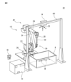
- FIG. 1 is a perspective view of a robot system according to one embodiment
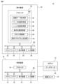
- FIG. 2 is a block diagram of the robot system shown in FIG. 1
- FIG. 2 is an enlarged view of the hand shown in FIG. 1
- FIG. It is a figure of a work concerning one embodiment.
- 5 shows a state in which the work shown in FIG. 4 is gripped by the hand shown in FIG.
- the visual sensor shown in FIG. 1 is an example of image data obtained by imaging a workpiece gripped by a hand.
- FIG. 7 schematically shows a state in which a workpiece model is applied to the image data shown in FIG. 6.
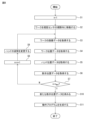
- FIG. 4 is a flow chart showing an example of a method of teaching a position and posture for gripping a workpiece with a hand to the robot in the robot system shown in FIG. 1;
- FIG. 1 The robot system 10 performs the work of picking up the works W randomly stacked in the container A, and includes a robot 12 , a visual sensor 14 , a control device 16 and a teaching device 18 .
- the robot 12 is a vertical articulated robot, and has a robot base 20, a swinging trunk 22, a lower arm 24, an upper arm 26, a wrist 28, and a hand 30.
- a robot base 20 is fixed on the floor of the work cell.
- the swing barrel 22 is provided on the robot base 20 so as to be rotatable about a vertical axis.
- the lower arm 24 is provided on the swing barrel 22 so as to be rotatable around the horizontal axis, and the upper arm 26 is rotatably provided at the tip of the lower arm 24 .
- the wrist portion 28 is rotatably provided at the distal end portion of the upper arm portion 26 .
- a plurality of servo motors 40 are provided in the robot base 20, the swing body 22, the lower arm section 24, the upper arm section 26, and the wrist section 28, respectively.
- the servomotor 40 rotates the swing barrel 22 , the lower arm 24 , the upper arm 26 and the wrist 28 around the drive shafts in response to commands from the control device 16 , thereby operating the robot 12 .
- the robot base 20 , swing body 22 , lower arm section 24 , upper arm section 26 and wrist section 28 are referred to as the mechanical section 42 of the robot 12 .
- the hand 30 is detachably attached to the tip of the wrist 28 (so-called wrist flange) and moved by the mechanism 42 of the robot 12 .
- the hand 30 has a hand arm 32, claw portions 34 and 36, and a claw portion driving portion 38.
- the hand arm 32 is connected at its proximal end to the distal end of the wrist portion 28 .
- the claws 34 and 36 are provided at the tip of the hand arm 32 so as to be openable and closable.
- each of the claws 34 and 36 is a cylindrical rod member extending linearly.
- the pawl driving section 38 has, for example, a pneumatic or hydraulic cylinder or a servomotor, and opens and closes the pawl sections 34 and 36 according to commands from the control device 16 .
- the hand 30 can grip and release the work W by opening and closing the claws 34 and 36 .
- the visual sensor 14 images the workpiece W.
- a holding frame 44 is fixed above the floor of the workcell and places the visual sensor 14 in a stationary position above the container A. As shown in FIG.
- the visual sensor 14 is a three-dimensional visual sensor having an imaging sensor (CMOS, CCD, etc.) and an optical lens (collimating lens, focus lens, etc.) for guiding a subject image to the imaging sensor. , an object is imaged along the line-of-sight direction VL, and the distance d to the object image is measured.
- the teaching device 18 teaches the operation of the robot 12 gripping the workpiece W randomly stacked in the container A with the hand 30 .
- the teaching device 18 is, for example, a portable computer such as a teaching pendant or tablet terminal device, and has a processor 50, a memory 52, an I/O interface 54, a display device 56, and an input device 58.
- the processor 50 has a CPU, GPU, or the like, and is communicably connected to a memory 52, an I/O interface 54, a display device 56, and an input device 58 via a bus 60. While communicating with these components, Arithmetic processing is performed to realize the teaching function.
- the memory 52 has RAM, ROM, etc., and temporarily or permanently stores various data.
- the I/O interface 54 has, for example, an Ethernet (registered trademark) port, a USB port, an optical fiber connector, or an HDMI (registered trademark) terminal, and exchanges data with external devices under instructions from the processor 50. Communicate by wire or wirelessly.
- the display device 56 has a liquid crystal display, an organic EL display, or the like, and visually displays various data under commands from the processor 50 .
- the input device 58 has push buttons, a keyboard, a mouse, a touch panel, or the like, and receives input data from the operator.
- the teaching device 18 is configured to be able to send commands to the robot 12 via the control device 16 according to input data to the input device 58, and jog the robot 12 according to the commands.
- the display device 56 and the input device 58 may be integrated into the housing of the teaching device 18, or may be externally attached to the housing of the teaching device 18 as separate bodies. .
- controller 16 controls the operations of the robot 12 and the visual sensor 14.
- controller 16 is a computer having processor 70 , memory 72 , I/O interface 74 , display 76 , and input device 78 .
- the configuration and function of processor 70, memory 72, I/O interface 74, display device 76, and input device 78 are similar to processor 50, memory 52, display device 56, and input device 58 described above, and thus are redundant. Description is omitted.
- Processor 70 is communicatively connected to memory 72, I/O interface 74, display device 76, and input device 78 via bus 80 and communicates with these components to operate robot 12 and vision sensor 14. Arithmetic processing is performed to realize functions.
- the I/O interface 54 of the teacher 18, each servo motor 40 of the robot 12, and the vision sensor 14 are connected to an I/O interface 74 through which the processor 70 communicates with these components.
- a robot coordinate system C1 is set in the mechanism section 42 of the robot 12.
- the robot coordinate system C ⁇ b>1 is a control coordinate system C for automatically controlling the action of the robot 12 gripping the work W with the hand 30 .
- the robot coordinate system C1 is set with respect to the mechanism section 42 such that its origin is located at the center of the robot base 20 and its z-axis coincides with the rotation axis of the swing body 22.
- a tool coordinate system C2 is set for the hand 30 of the robot 12, as shown in FIG.
- the tool coordinate system C2 is the control coordinate system C and defines the position and orientation of the hand 30 in the robot coordinate system C1.
- the tool coordinate system C2 has its origin located at the intermediate position between the claws 34 and 36, its y-axis direction parallel to the opening/closing direction of the claws 34 and 36, and its z-axis The direction is set with respect to the hand 30 so as to be parallel to the extending directions of the respective claws 34 and 36 .
- the positional relationship between the tool coordinate system C2 and the robot coordinate system C1 is known. , are mutually convertible. Therefore, the origin position and the direction of each axis of the tool coordinate system C2 in the robot coordinate system C1 are expressed as coordinates ( XRT , YRT , ZRT , WRT , PRT , RRT ) of the robot coordinate system C1.
- the coordinates ( XRT , YRT , ZRT ) indicate the origin position of the tool coordinate system C2 in the robot coordinate system C1
- the coordinates ( WRT , PRT , RRT ) indicate the tool position in the robot coordinate system C1.
- the direction of each axis (so-called yaw, pitch, roll) of the coordinate system C2 is shown.
- the processor 70 of the control device 16 When positioning the hand 30 at a predetermined position and orientation by the mechanism section 42 of the robot 12, the processor 70 of the control device 16 first sets the tool coordinate system C2 representing the predetermined position and orientation to the robot coordinate system C1. . Then, the processor 70 generates a command to each servo motor 40 so as to place the hand 30 in the position and orientation defined by the set tool coordinate system C2, and operates the mechanism section 42 according to the command. By doing so, the hand 30 is moved. In this way, the processor 70 can position the hand 30 at a predetermined position and posture in the robot coordinate system C1 by operating the mechanism section 42 .
- the visual sensor 14 is set with a sensor coordinate system C3.
- the sensor coordinate system C3 is the control coordinate system C, defines the position and orientation (that is, line-of-sight direction VL) of the visual sensor 14 in the robot coordinate system C1, and stores image data captured by the visual sensor 14 (or It defines the coordinates of each pixel of the image sensor).
- the sensor coordinate system C3 is set with respect to the visual sensor 14 such that its origin is located at the center of the imaging sensor and its z-axis direction coincides with the line-of-sight direction VL of the visual sensor 14.
- the visual sensor 14 is arranged at a known position in the robot coordinate system C1 by the holding frame 44. More specifically, the positional relationship between the sensor coordinate system C3 and the robot coordinate system C1 is already known by calibration, and the coordinates of the sensor coordinate system C3 and the coordinates of the robot coordinate system C1 are obtained by using a known transformation matrix They are mutually transformable via M2 (for example, homogeneous transformation matrix). Thus, the position and orientation of the visual sensor 14 in the robot coordinate system C1 (that is, the origin position and the direction of each axis of the sensor coordinate system C3) are known.
- M2 for example, homogeneous transformation matrix
- the processor 70 of the control device 16 uses the visual sensor 14 to image the workpieces W randomly stacked in the container A, and based on the captured image data ID, moves the workpieces W to the robot 12 with the hand 30. is gripped and picked up from the container A.
- An example of the workpiece W is shown in FIG.
- the work W is, for example, a connecting rod for an automobile, and has a shaft portion W1, a large ring portion W2, and a small ring portion W3.
- the shaft portion W1 extends straight along the axis B.
- the large ring portion W2 is fixed to one end of the shaft portion W1 and has a through hole H1.
- the small ring portion W3 is fixed to the other end of the shaft portion W1 and has a through hole H2.
- a work coordinate system C4 is set for the work W.
- the work coordinate system C4 is the control coordinate system C and defines the position and orientation of the work W in the robot coordinate system C1.
- the work coordinate system C4 has its origin located at the center of the shaft portion W1, its y-axis parallel to (or coinciding with) the axis B, and its z-axis extending through the through holes H1 and It is set with respect to the work W so as to be parallel to the central axis of H2.
- FIG. 5 shows an example of a state in which the robot 12 grips the workpiece W with the hand 30.
- the hand 30 grips the large ring portion W2 of the work W with the claw portions 34 and 36 by opening the claw portions 34 and 36 while the claw portions 34 and 36 are inserted into the through hole H1.
- the robot 12 In order to cause the robot 12 to perform the action of gripping the work W as shown in FIG.
- a method of teaching the robot 12 to grip the workpiece W in the robot system 10 will be described below.
- the operator causes the hand 30 of the robot 12 to grip the workpiece W at a desired gripping position.
- the operator operates the teaching device 18 to jog the robot 12 to grip the workpiece W with the hand 30 .
- the operator While viewing the display device 56 of the teaching device 18, the operator operates the input device 58 to move the hand 30 by the mechanical portion 42 of the robot 12, thereby opening the claw portions 34 and 36 in the closed state. is inserted into the through hole H1 of the work W arranged in a predetermined storage place.
- the operator operates the input device 58 to open the claw portions 34 and 36, and presses the claw portions 34 and 36 against the inner wall surface of the through hole H1 to grip the workpiece W.
- the operator jogs the robot 12 so that the hand 30 grips the workpiece W at the desired gripping position.
- a case where the operator grips the workpiece W with the hand 30 at the gripping position shown in FIG. 5 will be described below.
- the operator operates the input device 58 to jog the robot 12, and moves the hand 30 by the mechanical section 42 of the robot 12 so that the work W gripped by the hand 30 is within the visual field of the visual sensor 14. .
- the operator operates the input device 58 to cause the visual sensor 14 to image the work W gripped by the hand 30 .
- the visual sensor 14 receives an imaging command from the teaching device 18 via the control device 16 and images the image data ID 1 of the workpiece W.
- FIG. An example of image data ID 1 is shown in FIG.
- image data ID 1 is three-dimensional image data.
- Processor 50 of teaching device 18 acquires image data ID 1 from visual sensor 14 through controller 16 and I/O interface 54 .
- the processor 50 includes the image data acquisition unit 82 that acquires the image data ID of the work W imaged by the visual sensor 14 while the robot 12 is gripping the work W with the hand 30. (Fig. 2).
- the processor 50 acquires work position data WPD 1 indicating the position and orientation of the work W in the robot coordinate system C1 when the visual sensor 14 captured the image data ID 1 .
- the processor 50 first acquires a work model WM that models the work W.
- This work model WM is, for example, a three-dimensional CAD model and is stored in the memory 52 in advance.
- the processor 50 analyzes the three-dimensional point cloud image of the workpiece W captured in the image data ID 1 , and matches the workpiece model WM with the workpiece W captured in the image data ID 1 . are arranged in the image data ID 1 in a simulated manner.
- FIG. 7 shows the work model WM arranged in image data ID 1 in a simulated manner. Note that the image of the hand 30 is omitted in FIG. 7 for easy understanding.
- the processor 50 sets the work coordinate system C4 with the positional relationship shown in FIG. 4 for the work model WM arranged in the image data ID 1 .
- This work coordinate system C4 indicates the position and orientation of the work W reflected in the image data ID 1 in the sensor coordinate system C3, and the coordinates Q SW_1 (X SW_1 , Y SW_1 , Z SW_1 , W SW_1 , P SW_1 , R SW_1 ) (first coordinates).
- the coordinates (X SW_1 , Y SW_1 , Z SW_1 ) indicate the origin position of the work coordinate system C4 in the sensor coordinate system C3, and the coordinates (W SW_1 , P SW_1 , R SW_1 ) indicate the work position in the sensor coordinate system C3.
- the direction of each axis (so-called yaw, pitch, roll) of the coordinate system C4 is shown.
- the processor 50 acquires the coordinates QSW_1 of the workpiece coordinate system C4 in the sensor coordinate system C3 as data indicating the position and orientation of the workpiece W captured in the image data ID 1 in the sensor coordinate system C3.
- the processor 50 transforms the obtained coordinates Q SW_1 into the robot coordinate system C1 using the transformation matrix M2 described above, so that the coordinates Q RW_1 ( XRW_1 , YRW_1 , ZRW_1 , WRW_1 , PRW_1 , RRW_1 ) (second coordinates).
- This coordinate QRW_1 is data indicating the position and orientation of the workpiece W (specifically, the workpiece model WM in FIG. 7) captured in the image data ID 1 in the robot coordinate system C1.
- the processor 50 acquires this coordinate QRW_1 as work position data WPD1 .
- the processor 50 functions as the work position acquisition unit 84 (FIG. 2) that acquires the work position data WPD 1 (coordinates Q RW — 1 ) based on the image data ID 1 .
- the processor 50 acquires hand position data HPD1 indicating the position and orientation of the hand 30 in the robot coordinate system C1 when the visual sensor 14 captured the image data ID1 . Specifically, the processor 50 calculates the coordinates Q RT — 1 (X RT — 1 , Y RT — 1 , Z RT — 1 , W RT — 1 , P RT — 1 , R RT — 1 ) (third coordinates) are acquired as hand position data HPD 1 .
- the processor 50 functions as the hand position acquisition unit 86 (FIG. 2) that acquires the hand position data HPD 1 (coordinates Q RT — 1 ).
- the processor 50 determines the positions of the hand 30 and the work W in the control coordinate system C when the visual sensor 14 captured the image data ID 1 .
- Acquire teaching position data TPD 1 that indicates the relationship.
- the processor 50 converts the coordinates Q RW_1 as the work position data WPD 1 to the hand position data WPD 1 based on the coordinates Q RW_1 obtained as the work position data WPD 1 and the coordinates Q RT_1 obtained as the hand position data HPD 1 . Convert to the coordinates of the tool coordinate system C2 represented by the coordinates QRT_1 as the data HPD1 .
- the coordinate Q RW_1 of the work coordinate system C4 in the robot coordinate system C1 is can be transformed into the tool coordinate system C2.
- the processor 50 determines the coordinates Q TW_1 (X TW_1 , Y TW_1 , Z TW_1 , W TW_1 , P TW_1 , RTW_1 ).
- This coordinate QTW_1 is the position and orientation of the work W (that is, the origin position of the work coordinate system C4 and each This is data indicating the direction of the axis).
- the processor 50 acquires this coordinate Q TW_1 as the teaching position data TPD1 .
- the processor 50 converts the coordinates Q RT_1 as the hand position data HPD 1 to the work position based on the coordinates Q RW_1 as the work position data WPD 1 and the coordinates Q RT_1 as the hand position data HPD 1 .
- the coordinates are converted into the coordinates of the workpiece coordinate system C4 represented by the coordinates QRW_1 as the data WPD1 .
- the processor 50 calculates the coordinates Q WT_1 (X WT_1 , Y WT_1 , Z WT_1 , W WT_1 , P WT_1 , W WT_1 , P WT_1 , of the tool coordinate system C2 in the work coordinate system C4 when the visual sensor 14 captured the image data ID 1 . RWT_1 ).
- This coordinate QWT_1 is the position and orientation of the hand 30 (that is, the origin position of the tool coordinate system C2 and each This is data indicating the direction of the axis).
- the processor 50 acquires this coordinate QWT_1 as the teaching position data TPD1 .
- the processor 50 controls the control coordinate system C ( tool coordinates It functions as a teaching position acquisition unit 88 (FIG. 1) that acquires teaching position data TPD1 (coordinates QTW_1 , coordinates QWT_1 ) indicating the positional relationship between the hand 30 and the work W in the system C2 and the work coordinate system C4).
- teaching position data TPD1 coordinates QTW_1 , coordinates QWT_1 .
- the operator After acquiring the teaching position data TPD 1 , the operator operates the input device 58 to change the posture of the hand 30 while gripping the workpiece W by operating the mechanism section 42 of the robot 12 . For example, the operator operates the input device 58 to move the hand 30 at a predetermined angle ⁇ ( For example, input data for rotating by 10°.
- the operator inputs an input to rotate the hand 30 by a predetermined angle ⁇ about the x-axis, y-axis, or z-axis of the work coordinate system C4 set in the robot coordinate system C1 at this time.
- the operator inputs input data to rotate the hand 30 around the y-axis (that is, the axis B) of the work coordinate system C4. good too.
- the processor 50 sends a command to the servo motor 40 of the robot 12 via the control device 16 according to the input data from the operator, and operates the mechanism section 42 so as to change the posture of the hand 30 gripping the work W. make it work.
- the processor 50 functions as a robot control section 90 ( FIG. 2 ) that operates the robot 12 so as to change the posture of the hand 30 .
- the operator operates the input device 58 to cause the visual sensor 14 to image the work W gripped by the hand 30, and the processor 50 functions as an image data acquisition unit 82.
- the image data ID 2 of the workpiece W is obtained.
- the processor 50 functions as the work position acquisition unit 84 and applies the work model WM to the image data ID 2 by the method described above, thereby obtaining the coordinates Q SW_2 (X SW_2 ) of the work coordinate system C4 in the sensor coordinate system C3.
- Y SW — 2 , Z SW — 2 , W SW — 2 , P SW — 2 , R SW — 2 ) (first coordinates).
- the processor 50 functions as the work position acquisition unit 84, and converts the acquired coordinates Q SW_2 into the robot coordinate system C1 by the above-described method, thereby obtaining work position data WPD 2 at the time of imaging of the image data ID 2 .
- coordinates QRW_2 ( XRW_2 , YRW_2 , ZRW_2 , WRW_2 , PRW_2 , RRW_2 ) (second coordinates) of the workpiece coordinate system C4 in the robot coordinate system C1.
- the processor 50 functions as the hand position acquisition unit 86 , and the coordinates Q RT_2 (X RT_2 , YRT_2 , ZRT_2 , WRT_2 , PRT_2 , RRT_2 ) (third coordinates).
- the processor 50 functions as the teaching position acquisition unit 88 and acquires the coordinates Q TW_2 (X TW_2 , Y TW_2 , Z TW_2 , W TW_2 , P TW_2 , R TW_2 ), or coordinates Q WT_2 (X WT_2 , Y WT_2 , Z WT_2 , W WT_2 , P WT_2 , R WT_2 ).
- the processor 50 functions as a work position acquisition unit 84 and uses the above-described method to obtain work position data WPD n when each image data ID n is captured: coordinates Q RW — n (X RW — n , Y RW — n , Z RW_n , W RW_n , P RW_n , R RW_n ), and functioning as the hand position acquisition unit 86, the hand position data HPD n when each image data ID n is captured by the method described above: Obtain the coordinates QRT_n ( XRT_n , YRT_n , ZRT_n , WRT_n , PRT_n , RRT_n ) respectively.
- the processor 50 functions as a teaching position acquiring unit 88, and acquires each workpiece position data WPD n (coordinates Q RW_n ) and each hand position data HPD n (coordinates Q RT_n ) by the method described above.
- Taught position data TPD n when each image data ID n is imaged based on ( XWT_n , YWT_n , ZWT_n , WWT_n , PWT_n , RWT_n ) are obtained respectively.
- the processor 50 can acquire a plurality of teaching position data TPD n corresponding to various postures of the hand 30 and the workpiece W.
- the processor 50 functions as the teaching position acquiring unit 88, and based on the acquired plurality of teaching position data TPD n , new teaching positions to be used for the operation of causing the robot 12 to actually grip the workpiece W with the hand 30.
- the processor 50 acquires the coordinates QTW_n ( XTW_n , YTW_n , ZTW_n , WTW_n , PTW_n , RTW_n ) of the tool coordinate system C2 as the teaching position data TPDn , a new teaching position A method for obtaining data TPD 0 will be described.
- the processor 50 performs processing PR1 for excluding coordinates outside a predetermined allowable range for each of the plurality of coordinates Q TW_n . Specifically, the processor 50 performs a process PR1 of excluding coordinates outside the allowable range for the coordinates ( XTW_n , YTW_n , ZTW_n ) representing the position among the coordinates QTW_n .
- the obtained coordinates Q TW_n are registered in the memory 52 as a valid coordinate group GRP, while the distance ⁇ n is outside the allowable range [ ⁇ th1 , ⁇ th2 ]. If yes (ie, ⁇ n ⁇ th1 or ⁇ th2 ⁇ n ), the acquired coordinate Q TW_n is excluded from the valid coordinate group GRP (or deleted from memory 52).
- the processor 50 calculates the allowable range for each of the coordinates X TW_n , Y TW_n , and Z TW_n in the coordinates Q TW_n as the calculated mean and standard deviation ⁇ and a predetermined coefficient ⁇ (for example, ⁇ is a positive using [X TW_AV - ⁇ X , X TW_AV + ⁇ X ] (that is, X TW_AV - ⁇ X ⁇ X TW_n ⁇ X TW_AV + ⁇ X ), [Y TW_AV - ⁇ Y , Y TW_AV + ⁇ Y ] (that is, Y TW_AV ⁇ ⁇ Y ⁇ Y TW_n ⁇ Y TW_AV + ⁇ Y ) and [Z TW_AV ⁇ ⁇ Z , Z TW_AV + ⁇ Z ] (that is, Z TW_AV ⁇ ⁇ Z ⁇ Z TW_n
- the processor 50 determines whether the coordinate X TW is within the allowable range [X TW_AV ⁇ X , X TW_AV + ⁇ X ], the coordinate Y TW_n is within the allowable range [Y TW_AV ⁇ Y , Y TW_AV + ⁇ Y ] and whether the coordinate Z TW_n is within the allowable range [Z TW_AV ⁇ Z , Z TW_AV + ⁇ Z ].
- the processor 50 registers the acquired coordinates Q TW_n as the valid coordinate group GRP, while the coordinates X TW , Y TW_n , and Z TW_n are outside the allowable range, the acquired coordinates Q TW_n are excluded from the valid coordinate group GRP.
- the processor 50 also performs a process PR1 of excluding coordinates outside the allowable range for the coordinates ( WTW_n , PTW_n , RTW_n ) representing the orientation among the coordinates QTW_n . Specifically, the processor 50 first represents the coordinates representing the attitude (W TW — n , P TW — n , R TW — n ) as a 3 ⁇ 3 known matrix M3 — n .
- the vector VT1_n represented by the three parameters in the first column is a unit vector representing the rotation component around the x-axis of the tool coordinate system C2
- the three parameters in the second column is a unit vector representing the rotation component about the y-axis of the tool coordinate system C2
- the vector VT3_n represented by the three parameters in the third column is z of the tool coordinate system C2 .
- processor 50 may generate vector VT1_n of matrix M3_n representing first coordinate QTW_n ( WTW_n , PTW_n , RTW_n ) and second coordinate QTW_n +1 ( WTW_n+1 , PTW_n+1 , RTW_n+1 ) as Calculate the inner product IP1 n of the matrix M3_n +1 representing the matrix M3_n +1 with the vector VT1_n+1 .
- This inner product IP1 n represents the angle ⁇ 1 (specifically, cos ⁇ 1) between the vector VT1_n and the vector VT1_n +1 , that is, the amount of change in the rotational component around the x-axis of the tool coordinate system C2.
- the processor 50 also determines the inner product IP3 n of the vector VT3 _n of the matrix M3 _n and the vector VT3 _n+1 of the matrix M3 _n +1 .
- This inner product IP3 n represents the angle ⁇ 3 (specifically, cos ⁇ 3) between the vector VT3_n and the vector VT3_n +1 , that is, the amount of change in the rotational component around the z-axis of the tool coordinate system C2.
- the processor 50 determines whether the determined inner product IP1 n is equal to or greater than a predetermined threshold value IP1 th (IP1 n ⁇ IP1 th ), and determines whether the determined inner product IP3 n exceeds the predetermined threshold value IP3 th It is determined whether or not (IP3 n ⁇ IP3 th ) is satisfied. If IP1 n ⁇ IP1 th and IP3 n ⁇ IP3 th , the processor 50 registers both the acquired first coordinate Q TW_n and second coordinate Q TW_n+1 in the memory 52 as a valid coordinate group GRP. .
- the processor 50 puts one of the acquired first coordinates Q TW_n and second coordinates Q TW_n+1 into the valid coordinates group GRP. (or deleted from memory 52). The operator may predetermine which of the first coordinate Q TW_n and the second coordinate Q TW_n+1 should be excluded.
- the processor 50 includes a vector VT1_n of the matrix M3_n representing the first coordinate QTW_n ( WTW_n , PTW_n , RTW_n ) and each coordinate QTW_i ( WTW_i , P TW_i , R TW_i ) and the vector VT1 _i (where “i” is a positive integer other than “n”) and the inner product IP1 i of the matrix M3 _i .
- the processor 50 calculates the inner product IP3 i of the vector VT3 _n of the matrix M3 _n of the first coordinate Q TW_n and the vector VT3 _i of the matrix M3 _i of each coordinate Q TW_i other than the first coordinate Q TW_n . can be obtained respectively.
- the processor 50 determines whether each of the calculated inner products IP1 i is equal to or greater than the threshold IP1 th (IP1 i ⁇ IP1 th ), and also determines whether each of the calculated inner products IP3 i is equal to or greater than the threshold IP3 th (IP3 i ⁇ IP3 th ).
- the processor 50 determines that at least one (or all) of the calculated inner products IP1 i satisfies IP1 i ⁇ IP1 th and at least one (or all) of the calculated inner products IP3 i satisfies IP3 i ⁇ IP3 If th is satisfied, the acquired first coordinate Q TW_n may be registered in the memory 52 as a valid coordinate group GRP.
- the processor 50 determines whether all (or at least one) of the calculated inner products IP1 i satisfies IP1 i ⁇ IP1 th , or all (or at least one) of the calculated inner products IP3 i is , IP3 i ⁇ IP3 th , the obtained first coordinate Q TW_n may be excluded from the valid coordinate group GRP. Processor 50 may repeat such process PR1 for all of the acquired coordinates Q TW_n .
- the processor 50 performs the excluding process PR1 for each of the plurality of coordinates Q TW_n .
- the coordinates Q TW_n obtained by erroneous detection can be excluded.
- the thresholds ⁇ th1 , ⁇ th2 , IP1 th , IP3 th , IP1 Rth , IP2 Rth or IP3 Rth are predetermined by the operator.
- the processor 50 After the excluding process PR1, the processor 50 performs a process of averaging the coordinates Q TW_m (m represents the number n of the coordinates Q TW_n registered in the valid coordinate group GRP) registered in the valid coordinate group GRP. Perform PR2. Specifically, the processor 50 calculates the average coordinates ( X TW_0 , Y TW_0 , Z TW_0 ).
- X TW_0 1/k ⁇ (X TW_m )
- Y TW_0 1/k ⁇ (Y TW_m )
- Z TW_0 1/k ⁇ (Z TW_m ).
- the average coordinates (X TW — 0 , Y TW — 0 , Z TW — 0 ) are obtained from the formula. Note that "k” in this formula indicates the number of coordinates Q TW_m registered in the effective coordinate group GRP.
- Processor 50 then obtains the outer product OP1 of the unit vector VT1 R ' of the composite vector VT1 R and the unit vector VT3 R ' of the composite vector VT3 R .
- This outer product OP1 represents a vector in a direction orthogonal to the unit vectors VT1 R ′ and VT3 R ′.
- the processor 50 then normalizes the vector represented by the outer product OP1 to obtain the unit vector VT2 R ′.
- the processor 50 then obtains the outer product OP2 of the unit vectors VT2 R ' and VT3 R ', and normalizes the vector represented by the outer product OP2 to obtain the unit vector VT1 R ''. 50 obtains the unit vectors VT1 R ′′, VT2 R ' and VT3 R '.
- the processor 50 then obtains the poses (W TW_0 , P TW_0 , RTW_0 ) represented by these unit vectors VT1 R ′′, VT2 R ' and VT3 R '.
- the direction of each axis of the coordinate system C4 is shown, the x-axis direction of the work coordinate system C4 is the direction of the above-mentioned unit vector VT1 R '', the y-axis direction is the direction of the above-mentioned unit vector VT2 R ', The z-axis direction is the direction of the unit vector VT3 R ′ described above.
- the processor 50 obtains the unit vector VT3 R ′ by normalizing the vector represented by the outer product OP3, obtains the outer product OP4 of the unit vector VT3 R ′ and the unit vector VT1 R ′, and obtains the outer product OP4
- the unit vector VT2 R ′′ may be obtained by normalizing the vector represented by .
- the processor 50 calculates from the unit vectors VT1 R ', VT2 R '' and VT3 R ' thus obtained the pose coordinates ( WTW_0 , PTW_0 , RTW_0 ) can be determined.
- the processor 50 performs the process PR2 of averaging the coordinates Q TW_m registered in the effective coordinate group GRP.
- the processor 50 can acquire the coordinates QTW_0 ( XTW_0 , YTW_0 , ZTW_0 , WTW_0 , PTW_0 , RTW_0 ) as the teaching position data TPD0 .
- This coordinate QTW_0 indicates the origin position ( XTW_0 , YTW_0 , ZTW_0 ) of the work coordinate system C4 in the tool coordinate system C2 and the direction of each axis ( WTW_0 , PTW_0 , RTW_0 ).
- the processor 50 functions as the teaching position acquisition unit 88 to obtain one teaching position data TPD 0 (coordinate Q TW_0 ).
- the processor 50 acquires the coordinates QWT_n ( XWT_n , YWT_n , ZWT_n , WWT_n , PWT_n , RWT_n ) of the tool coordinate system C2 in the work coordinate system C4 as the teaching position data TPDn .
- the coordinates QWT_0 ( XWT_0 , YWT_0 , ZWT_0, WWT_0 , PWT_0 , RWT_0 ) of the tool coordinate system C2 in the work coordinate system C4 are obtained as the new teaching position data TPD0 by the method described above. It should be understood that
- the processor 50 uses the obtained taught position data TPD 0 to generate an operation program OP in which the taught position data TPD 0 (that is, the coordinates Q TW_ or Q WT — 0 ) are defined as instruction codes. Therefore, the processor 50 functions as an operation program generator 92 (FIG. 2) that generates the operation program OP.
- the processor 70 of the control device 16 operates the robot 12 according to the operation program OP in the actual work line, and performs the operation of picking up the workpieces W randomly stacked in the container A by gripping them with the hand 30 .
- the processor 70 operates the visual sensor 14 to image the workpiece W in the container A, and acquires the imaged image data ID W (second image data) from the visual sensor 14 .
- the processor 70 acquires work position data representing the position and orientation of the work W reflected in the image data ID W in the robot coordinate system C1, based on the acquired image data ID W , in the same manner as the work position acquisition unit 84 described above.
- WPD W second work position data
- the processor 70 arranges the work model WM so as to match the work W shown in the image data ID W , and sets the work coordinate system C4 for the arranged work model WM.
- the processor 70 acquires the coordinates Q SW_W (X SW_W , Y SW_W , Z SW_W , W SW_W , P SW_W , R SW_W ) of the sensor coordinate system C3 of the set work coordinate system C4, and transfers the coordinates Q SW_W to the robot.
- Coordinates Q RW_W (X RW_W , Y RW_W , Z RW_W , W RW_W , P RW_W , R RW_W ) of work coordinate system C4 in robot coordinate system C1 are acquired as work position data WPD W by converting to coordinate system C1. do.
- the processor 70 acquires work position data WPD W (coordinates Q RW — W ) indicating the position and orientation of the work W in the robot coordinate system C1.
- the processor 70 determines the robot coordinate system when gripping the workpiece W imaged by the visual sensor 14. The position and posture of the hand 30 at C1 are determined.
- the processor 70 uses the coordinates Q RW_W acquired as the work position data WPD W and the teaching position data TPD 0 (specifically, the coordinates Q TW_0 or Q WT_0 ) to express the position with the coordinates Q RW_W .
- Coordinates QRT_0 XRT_0 , YRT_0 , ZRT_0, WRT_0 , PRT_0 , RRT_0 ) of the robot coordinate system C1 having the positional relationship indicated by the teaching position data TPD0 with respect to the workpiece coordinate system C4 to be demand.
- the processor 70 determines the position and posture of the hand 30 when gripping the workpiece W by setting the tool coordinate system C2 to the obtained coordinate Q RT_0 in the robot coordinate system C1.
- the processor 70 arranges the hand 30 with the claws 34 and 36 in the closed state at the position and orientation defined by the tool coordinate system C2 set to the coordinates QRT_0 of the robot coordinate system C1.
- the hand 30 is moved.
- the claw portions 34 and 36 are inserted into the through holes H1 of the workpiece W. As shown in FIG.
- the processor 70 operates the claw portion driving portion 38 to open the claw portions 34 and 36, thereby gripping the large ring portion W2 of the workpiece W with the claw portions 34 and 36.
- FIG. 5 As a result, as shown in FIG. 5, the hand 30 can grip the workpiece W at the gripping position taught by the taught position data TPD0 .
- the processor 70 can pick up the work W by operating the mechanism section 42 to withdraw the hand 30 that grips the work W from the container A. After that, the processor 70 repeatedly executes the series of operations described above for each workpiece W randomly stacked in the container A, thereby picking up the workpiece W randomly stacked in the container A with the hand 30. perform the work.
- the processor 50 of the teaching device 18 includes the image data acquisition section 82, the work position acquisition section 84, the hand position acquisition section 86, the teaching position acquisition section 88, the robot control section 90, and the operation It functions as the program generation unit 92 and teaches the position and posture of the robot 12 to grip the workpiece W with the hand 30 in the robot coordinate system C1.
- the image data acquisition unit 82, the workpiece position acquisition unit 84, the hand position acquisition unit 86, the teaching position acquisition unit 88, the robot control unit 90, and the operation program generation unit 92 are configured so that the robot 12 grips the workpiece W with the hand 30.
- a device 100 (FIG. 2) for teaching position and orientation is constructed. That is, in this embodiment, the device 100 is implemented in the teaching device 18 and the processor 50 of the teaching device 18 performs the functions of the device 100 .
- the image data acquisition unit 82 when the robot 12 is gripping the work W with the hand 30, detects the visual sensor 14 arranged at a known position in the control coordinate system C (robot coordinate system C1). obtains the image data ID n obtained by imaging the workpiece W, and the workpiece position obtaining unit 84, based on the image data ID n , obtains the image data ID n in the control coordinate system C (robot coordinate system C1) at the time of imaging the image data ID n.
- Work position data WPD n indicating the position and orientation of the work W is acquired.
- the hand position obtaining unit 86 obtains hand position data HPD n indicating the position and orientation of the hand 30 in the control coordinate system C (robot coordinate system C1) at the time of imaging of the image data ID n
- the teaching position obtaining unit 88 is based on the work position data WPD n and the hand position data HPD n , the position of the hand 30 and the work W in the control coordinate system C (tool coordinate system C2, work coordinate system C4) at the time of imaging of the image data ID n .
- Acquire teaching position data TPD n indicating the positional relationship.
- the gripping position that the operator wants to teach can be obtained.
- the position can be taught to the robot 12 with high accuracy.
- the robot control unit 90 operates the robot 12 so as to repeatedly change the posture of the hand 30 gripping the work W, and the image data acquisition unit 82 controls the robot control unit 90 to change the posture of the hand 30 .
- a plurality of image data ID n picked up by the visual sensor 14 are acquired each time the posture of is changed.
- the work position acquisition unit 84 acquires work position data WPD n based on each image data ID n
- the hand position acquisition unit 86 acquires hand position data HPD n at the time of imaging of each image data ID n . respectively.
- the teaching position acquisition unit 88 acquires teaching position data TPD n at the time of imaging of each image data ID n based on each work position data WPD n and each hand position data HPD n .
- the gripping position of the workpiece W can be taught to the robot 12 with higher accuracy.
- the teaching position acquisition unit 88 obtains new teaching position data TPD 0 to be used for the operation of causing the robot 12 to grip the workpiece W with the hand 30, based on a plurality of teaching position data TPD n .
- the hand 30 can grasp the work W in various postures. can be determined with higher accuracy by the taught position data TPD 0 .
- the teaching position data TPD n are expressed as coordinates QTW_n and QWT_n of the control coordinate system C (the tool coordinate system C2 and the work coordinate system C4).
- New teaching position data TPD 0 is obtained by excluding the coordinates outside the predetermined allowable range from the coordinates Q TW_n and Q WT_n of the position data TPD n and calculating the average of the coordinates Q TW_m and Q WT_m .
- the operation program generator 92 generates an operation program OP in which the teaching position data TPD 0 is defined. According to this configuration, it is possible to automatically generate the operation program OP that defines the teaching position data TPD 0 acquired as described above.
- the work position acquisition unit 84 also determines the control coordinate system C Data indicating the position and orientation in (robot coordinate system C2) is acquired as workpiece position data WPD n .
- the workpiece position data WPD n can be detected with high accuracy from the image data ID n captured by the visual sensor 14 .
- control coordinate system C includes the robot coordinate system C1, the work coordinate system C4, the tool coordinate system C2 whose positional relationship with the robot coordinate system C1 is known, and the position of the robot coordinate system C1. and a sensor coordinate system C3 with a known relationship, and the visual sensor 14 is placed at a known position in the robot coordinate system C1.
- the work position obtaining unit 84 obtains a first coordinate Q SW_n in the sensor coordinate system C3 of the work coordinate system C4 indicating the position and orientation of the work W reflected in the image data ID n , and obtains the first coordinate Q SW_n .
- the second coordinate QRW_n of the work coordinate system C4 in the robot coordinate system C1 is acquired as work position data WPDn .
- the hand position acquisition unit 86 acquires the third coordinate Q RT_n in the robot coordinate system C1 of the tool coordinate system C2 indicating the position and orientation of the hand 30 as the hand position data HPD n .
- the teaching position data TPD n is converted to the coordinate Q TW_n of the work coordinate system C4 in the tool coordinate system C2 or the coordinate Q of the tool coordinate system C2 in the work coordinate system C4. WT_n .
- the teaching position data TPD n is converted to the coordinate Q It can be taken as TW_n or QWT_n .
- the present invention is not limited to this, and the processor 50 performs the following operations: change in posture of the hand 30, acquisition of image data ID n , acquisition of work position data WPD n , acquisition of hand position data HPD n , and acquisition of teaching position data TPD n .
- a series of operations may be automatically executed.
- FIG. 8 The flow shown in FIG. 8 is started when the processor 50 of the teaching device 18 receives the teaching start command CM.
- the operator operates the input device 58 of the teaching device 18 to input a teaching start command CM to the teaching device 18 when the work W is gripped by the hand 30 as shown in FIG.
- step S1 the processor 50 sets a number "n” that defines the number of teaching position data TPD n to be acquired to "1".
- This number "n” corresponds to "n" of the image data ID n , work position data WPD n , hand position data HPD n , and teaching position data TPD n described above.
- step S ⁇ b>2 the processor 50 operates the mechanism section 42 of the robot 12 to move the workpiece W gripped by the hand 30 within the visual field of the visual sensor 14 .
- processor 50 may move hand 30 along a predetermined movement path. This movement path can be determined by pre-teaching the robot 12 by the operator.
- the processor 50 may acquire coordinates of the tool coordinate system C2 and the sensor coordinate system C3 in the robot coordinate system C1, and move the hand 30 based on the coordinates.
- step S3 the processor 50 functions as the image data acquisition unit 82 and acquires the image data ID n .
- the processor 50 sends an imaging command to the visual sensor 14 to operate the visual sensor 14 to image the image data ID n of the work W gripped by the hand 30 .
- the processor 50 then functions as the image data acquisition unit 82 and acquires the image data ID n from the visual sensor 14 .
- step S4 the processor 50 functions as the work position acquisition unit 84, and based on the image data ID n acquired in the most recent step S3, the work position data WPD n (for example, coordinates Q RW — n ) by the method described above.
- step S5 the processor 50 functions as the hand position obtaining unit 86, and obtains the hand position data HPDn (for example, coordinates QRT_n ) at the time of imaging of the most recent image data IDn obtained in step S3 by the method described above. to get
- step S6 the processor 50 functions as the teaching position acquisition unit 88, and acquires the work position data WPD n acquired in the most recent step S4 and the hand position data HPD n acquired in the most recent step S5 by the method described above.
- teach position data TPD n (for example, coordinates Q TW_n or Q WT_n ) are obtained based on .
- step S9 the processor 50 functions as the robot control section 90 to operate the mechanism section 42 of the robot 12 to change the posture of the hand 30 that grips the workpiece W. Specifically, the processor 50 rotates the hand 30 by a predetermined angle ⁇ about the x-axis, y-axis, or z-axis of the tool coordinate system C2 set in the robot coordinate system C1 at this time.
- the processor 50 moves the hand 30 around the x-axis, the y-axis (that is, the axis B of the workpiece W), or the z-axis of the work coordinate system C4 set in the robot coordinate system C1 at this time. It may be rotated by an angle ⁇ .
- the angle ⁇ and direction for rotating the hand 30 when executing this step S9 may be predetermined by the operator, or may be set at this point each time the processor 50 executes step S9.
- the work W is automatically (for example, randomly) positioned so that the entire work W is within the field of view of the visual sensor 14. to).
- step S9 the processor 50 returns to step S3 and repeatedly executes the loop of steps S3 to S9 until YES is determined in step S7.
- step S10 the processor 50 functions as the teaching position acquisition unit 88, and acquires new teaching position data based on the plurality of teaching position data TPD n acquired by the method described above.
- Determine TPD 0 eg, coordinate Q TW — 0 or Q WT — 0 ).
- step S11 the processor 50 functions as the operation program generation unit 92 and generates the operation program OP in which the teaching position data TPD 0 (that is, the coordinates Q TW_0 or Q WT_0 ) is defined, as in the above-described embodiment. do.
- the processor 50 can automatically generate the operation program OP by automatically executing the series of operations of steps S1 to S11. With this configuration, the process of teaching the robot 12 where to grip the workpiece W can be expedited and simplified.
- the processor 50 may function as the robot control unit 90 to change the position of the hand 30 instead of changing the posture of the hand 30 .
- the processor 50 operates the mechanism section 42 of the robot 12 to move the hand 30 to the tool coordinate system C2 set to the robot coordinate system C1 at this time (or to the work coordinate system
- the position of the hand 30 may be changed by translating it by a predetermined distance ⁇ in the direction of the x-axis, y-axis, or z-axis of C4).
- “translational movement” can be defined as an operation of moving the hand 30 without changing the posture of the hand 30 (that is, the direction of each axis of the tool coordinate system C2).
- the processor 50 may alternately execute the action of changing the attitude of the hand 30 and the action of changing the position of the hand 30 each time step S9 is executed, or alternatively, the process of step S9 , the posture of the hand 30 may be changed and the position of the hand 30 may be changed.
- the functions of the device 100 can also be implemented in the control device 16 (or the visual sensor 14).
- the processor 70 of the control device 16 is the device 100 (that is, the image data acquisition unit 82, the work position acquisition unit 84, the hand position acquisition unit 86, the teaching position acquisition unit 88, the robot It functions as a control unit 90 and an operation program generation unit 92).
- Some of the image data acquisition unit 82, workpiece position acquisition unit 84, hand position acquisition unit 86, teaching position acquisition unit 88, robot control unit 90, and operation program generation unit 92 are 18 , and one of the visual sensors 14 , while other portions may be implemented in the other one of the controller 16 , the teacher 18 , and the visual sensor 14 .
- the image data acquisition unit 82 is implemented in the visual sensor 14, the workpiece position acquisition unit 84, the hand position acquisition unit 86, and the robot control unit 90 are implemented in the control device 16, the teaching position acquisition unit 88, and the operation
- the program generator 92 may be implemented in the teaching device 18 .
- the processor of the visual sensor 14, the processor 70 of the control device 16, and the processor 50 of the teaching device 18 constitute the device 100.
- the processor 50 functions as the hand position acquisition unit 86, acquires data indicating the position and orientation of the hand 30 in the sensor coordinate system C2 based on the image data ID n , and from the data, Hand position data HPD n may be obtained.
- the visual sensor 14 picks up the image data ID n with the work W and the hand 30 holding the work W within its field of view.
- This hand model 30M is, for example, a three-dimensional CAD model and is stored in the memory 52 in advance.
- the processor 50 analyzes the three-dimensional point cloud image of the hand 30 captured in the image data ID n using predetermined pattern matching parameters, and transfers the hand model 30M to the hand 30 captured in the image data ID n. Arrange them simulatively so that they match.
- the processor 50 sets the tool coordinate system C2 with the positional relationship shown in FIG. 3 for the hand model 30M arranged in the image data ID n .
- the processor 50 acquires the coordinates Q ST_n in the sensor coordinate system C3 of the set tool coordinate system C2, and transforms the coordinates Q ST_n into the robot coordinate system C1 to obtain hand position data HPD n (coordinates Q RT_n ).
- Such functions can also be performed by the visual sensor 14 .
- the visual sensor 14 (specifically, the processor) applies the work model WM and the hand model 30M to the captured image data ID n to obtain the coordinates Q ST_n of the tool coordinate system C2 in the sensor coordinate system C3, Coordinates QSW_n of the workpiece coordinate system C4 in the sensor coordinate system C3 may be acquired and provided to the teaching device 18 .
- the visual sensor 14 functions as the work position acquisition unit 84 to acquire the coordinates Q SW_n of the work coordinate system C4 in the sensor coordinate system C3 as the work position data WPD n , and the hand position acquisition unit 86 and acquires the coordinates Q ST_n of the tool coordinate system C2 in the sensor coordinate system C3 as the hand position data HPD n .
- the visual sensor 14 functions as a teaching position acquisition unit 88 and acquires teaching position data TPD n (for example, coordinates Q TW_n or Q WT_n ) may be obtained. That is, the processor of the visual sensor 14 functions as the device 100 in this case.
- the processor 50 performs the exclusion processing PR1 on each of the plurality of coordinates Q TW_n or Q WT_n , and then the coordinates Q TW_m or Q registered in the valid coordinate group GRP.
- the case of performing the process PR2 for averaging WT_n has been described.
- the present invention is not limited to this, and the processor 50 may perform only one of the excluding process PR1 and the averaging process PR2 for a plurality of coordinates Q TW_n or Q WT_n .
- the processor 50 may obtain new taught position data TPD 0 by executing a process PR2 of averaging a plurality of acquired coordinates Q TW_n or Q WT_n without performing the exclusion process PR1.
- the processor 50 performs only the process PR1 for excluding a plurality of coordinates Q TW_n or Q WT_n , and as a result of the process PR1, from the coordinates Q TW_m or Q WT_n registered in the valid coordinate group GRP,
- One teaching position data TPD 0 may be automatically selected according to a defined condition.
- the processor 50 obtains new taught position data TPD 0 based on a plurality of acquired taught position data TPD n .
- the present invention is not limited to this, and the processor 50 may generate, for example, image data in which a plurality of acquired teaching position data TPD n are displayed in a list format, and cause the display device 56 to display the image data.
- the operator operates the input device 58 to provide the processor 50 with input data for selecting desired teaching position data TPD 0 from a plurality of teaching position data TPD n displayed on the display device 56 .
- the processor 50 creates an operation program OP that defines the teaching position data TPD 0 selected by the operator.
- the processor 50 functions as the robot control unit 90 to repeatedly change the posture of the hand 30, thereby obtaining a plurality of teaching position data TPDn .
- the present invention is not limited to this, and the processor 50 may acquire only the teaching position data TPD 1 described above without changing the posture of the hand 30 .
- the processor 50 may create an operating program OP in which the taught position data TPD1 is defined. That is, in this case, the robot controller 90 can be omitted from the device 100 .
- the processor 50 functions as the operating program generator 92 and creates the operating program OP
- the present invention is not limited to this, and the operator may manually create the operation program OP based on the teaching position data TPD n acquired by the processor 50 . That is, in this case, the operating program generator 92 can be omitted from the device 100 .
- the processor 50 obtains the work position data WPD n by applying the work model WM to the image data ID n .
- the processor 50 can also acquire the work position data WPD n by analyzing the image of the work W appearing in the image data ID n without using the work model WM.
- the teaching position data TPD n is acquired with reference to the robot coordinate system C1, the tool coordinate system C2, the sensor coordinate system C3, and the work coordinate system C4 as the control coordinate system C has been described. rice field.
- the teaching position data TPD n can also be obtained with the world coordinate system C5 as a reference, for example.
- the world coordinate system C5 is a control coordinate system C that defines the three-dimensional space of the work cell, and is set fixed to the work cell.
- the visual sensor 14 may be fixed to the mechanical portion 42 (for example, the upper arm portion 26 or the lower arm portion 24) of the robot 12 instead of the holding frame 44.
- the visual sensor 14 is attached to the mechanism section 42 so as to be able to image the work W gripped by the hand 30 .
- the work position data WPD n , the hand position data HPD n , and the teaching position data TPD n are the coordinates Q of the control coordinate system C has been described, but the present invention is not limited to this. may be represented as any data of
- the hand 30 may grip the small ring portion W3 by pressing the claw portions 34 and 36 against the inner wall surface of the through hole H2.
- the teaching device 50 teaches the position and posture for gripping the small ring portion W3 with the hand 30 by the same method as in the above-described embodiment.
- the workpiece W is not limited to the form (connecting rod) shown in FIG. 4, and may be of any shape, and the hand 30 may be of any type.
- the hand 30 may have a suction portion (a vacuum device, a suction cup, a magnet, etc.) instead of the claw portions 34 and 36 that can be opened and closed, and the suction portion may suction-hold the workpiece W. .
- the visual sensor 14 may be a two-dimensional camera.
- the robot system 10 may further include a distance sensor fixed to the visual sensor 14 and capable of measuring the distance d between the visual sensor 14 and the object (workpiece W).
- the teaching device 18 may be directly connected to the robot 12 (servo motor 40 ) or the visual sensor 14 .
Landscapes
- Engineering & Computer Science (AREA)
- Physics & Mathematics (AREA)
- General Physics & Mathematics (AREA)
- Automation & Control Theory (AREA)
- Robotics (AREA)
- Mechanical Engineering (AREA)
- Manipulator (AREA)
- Numerical Control (AREA)
Abstract
De manière classique, il existe un besoin pour des technologies permettant un apprentissage très précis d'une position au niveau de laquelle un robot est amené à saisir une pièce d'une main. Un dispositif (100) comporte : une unité d'acquisition de données d'image (82) qui acquiert, lorsqu'un robot (12) saisit une pièce d'une main, des données d'image de la pièce imagées par un capteur visuel (14) disposé au niveau d'une position connue sur un système de coordonnées de commande ; une unité d'acquisition de position de pièce (84) qui acquiert des données de position de pièce indiquant une position et une posture de la pièce sur la base des données d'image ; une position d'acquisition de position de main (86) qui acquiert des données de position de main indiquant une position et une posture de la main obtenue lorsque le capteur visuel a imagé les données d'image ; et une unité d'acquisition de position d'apprentissage (88) qui acquiert, sur la base des données de position de pièce et des données de position de main, des données de position d'apprentissage indiquant une relation de position entre la main et la pièce obtenue lorsque le capteur visuel (14) a imagé les données d'image.
Priority Applications (5)
| Application Number | Priority Date | Filing Date | Title |
|---|---|---|---|
| CN202180101401.4A CN117836099A (zh) | 2021-08-20 | 2021-08-20 | 对机器人把持工件的位置以及姿势进行示教的装置、机器人系统以及方法 |
| DE112021007813.5T DE112021007813T5 (de) | 2021-08-20 | 2021-08-20 | Vorrichtung zum lehren von position und haltung für einen roboter zum greifen eines werkstücks, robotersystem und verfahren |
| PCT/JP2021/030660 WO2023021703A1 (fr) | 2021-08-20 | 2021-08-20 | Dispositif d'apprentissage de position et de posture pour robot pour la saisie d'une pièce, système de robot et procédé |
| JP2023542167A JPWO2023021703A1 (fr) | 2021-08-20 | 2021-08-20 | |
| TW111127770A TW202308819A (zh) | 2021-08-20 | 2022-07-25 | 教示機器人把持工件的位置及姿勢的裝置、機器人系統、及方法 |
Applications Claiming Priority (1)
| Application Number | Priority Date | Filing Date | Title |
|---|---|---|---|
| PCT/JP2021/030660 WO2023021703A1 (fr) | 2021-08-20 | 2021-08-20 | Dispositif d'apprentissage de position et de posture pour robot pour la saisie d'une pièce, système de robot et procédé |
Publications (1)
| Publication Number | Publication Date |
|---|---|
| WO2023021703A1 true WO2023021703A1 (fr) | 2023-02-23 |
Family
ID=85240384
Family Applications (1)
| Application Number | Title | Priority Date | Filing Date |
|---|---|---|---|
| PCT/JP2021/030660 WO2023021703A1 (fr) | 2021-08-20 | 2021-08-20 | Dispositif d'apprentissage de position et de posture pour robot pour la saisie d'une pièce, système de robot et procédé |
Country Status (5)
| Country | Link |
|---|---|
| JP (1) | JPWO2023021703A1 (fr) |
| CN (1) | CN117836099A (fr) |
| DE (1) | DE112021007813T5 (fr) |
| TW (1) | TW202308819A (fr) |
| WO (1) | WO2023021703A1 (fr) |
Citations (3)
| Publication number | Priority date | Publication date | Assignee | Title |
|---|---|---|---|---|
| JP5588089B1 (ja) * | 2012-11-22 | 2014-09-10 | パナソニック株式会社 | アームの制御装置及び制御方法及び制御プログラム、ロボット、並びに、アームの制御用集積電子回路 |
| JP6326765B2 (ja) * | 2013-11-06 | 2018-05-23 | セイコーエプソン株式会社 | 教示装置、ロボット、ロボットシステム、方法、及びプログラム |
| WO2021145311A1 (fr) * | 2020-01-17 | 2021-07-22 | ファナック株式会社 | Dispositif de commande pour robot, système de robot, procédé de commande et programme |
Family Cites Families (1)
| Publication number | Priority date | Publication date | Assignee | Title |
|---|---|---|---|---|
| JP6117853B2 (ja) | 2015-05-13 | 2017-04-19 | ファナック株式会社 | バラ積みされた物品を取り出すための物品取出システム、および方法 |
-
2021
- 2021-08-20 JP JP2023542167A patent/JPWO2023021703A1/ja active Pending
- 2021-08-20 DE DE112021007813.5T patent/DE112021007813T5/de active Pending
- 2021-08-20 WO PCT/JP2021/030660 patent/WO2023021703A1/fr active Application Filing
- 2021-08-20 CN CN202180101401.4A patent/CN117836099A/zh active Pending
-
2022
- 2022-07-25 TW TW111127770A patent/TW202308819A/zh unknown
Patent Citations (3)
| Publication number | Priority date | Publication date | Assignee | Title |
|---|---|---|---|---|
| JP5588089B1 (ja) * | 2012-11-22 | 2014-09-10 | パナソニック株式会社 | アームの制御装置及び制御方法及び制御プログラム、ロボット、並びに、アームの制御用集積電子回路 |
| JP6326765B2 (ja) * | 2013-11-06 | 2018-05-23 | セイコーエプソン株式会社 | 教示装置、ロボット、ロボットシステム、方法、及びプログラム |
| WO2021145311A1 (fr) * | 2020-01-17 | 2021-07-22 | ファナック株式会社 | Dispositif de commande pour robot, système de robot, procédé de commande et programme |
Also Published As
| Publication number | Publication date |
|---|---|
| DE112021007813T5 (de) | 2024-03-28 |
| CN117836099A (zh) | 2024-04-05 |
| JPWO2023021703A1 (fr) | 2023-02-23 |
| TW202308819A (zh) | 2023-03-01 |
Similar Documents
| Publication | Publication Date | Title |
|---|---|---|
| US9517563B2 (en) | Robot system using visual feedback | |
| JP6429450B2 (ja) | 情報処理装置、情報処理方法 | |
| US8406923B2 (en) | Apparatus for determining pickup pose of robot arm with camera | |
| WO2018137445A1 (fr) | Procédé et système de préhension de bras mécanique basés sur ros | |
| JP5742862B2 (ja) | ロボット装置及び被加工物の製造方法 | |
| US20160184996A1 (en) | Robot, robot system, control apparatus, and control method | |
| CN113021358B (zh) | 机械臂工具坐标系原点标定方法、装置和电子设备 | |
| JP7130927B2 (ja) | 制御装置およびロボットシステム | |
| JP6897396B2 (ja) | 制御装置、ロボットシステムおよび制御方法 | |
| WO2016193781A1 (fr) | Système de commande de mouvement pour un robot à entraînement direct par asservissement visuel | |
| WO2020190166A1 (fr) | Procédé et système de saisie d'objet à l'aide d'un dispositif robotisé | |
| JP2018167334A (ja) | 教示装置および教示方法 | |
| JP2020012669A (ja) | 物体検査装置、物体検査システム、及び検査位置を調整する方法 | |
| JP2018051634A (ja) | ロボット制御装置、ロボット、ロボットシステムおよび姿勢特定装置 | |
| JP2006026790A (ja) | 教示モデル生成装置 | |
| WO2023021703A1 (fr) | Dispositif d'apprentissage de position et de posture pour robot pour la saisie d'une pièce, système de robot et procédé | |
| Zhang et al. | Vision-guided robotic assembly using uncalibrated vision | |
| CN117103277A (zh) | 一种基于多模态数据融合的机械手臂感知方法 | |
| WO2021210456A1 (fr) | Dispositif permettant d'obtenir la position d'un capteur visuel dans un système de coordonnées de commande d'un robot, système de robot, procédé et programme informatique | |
| CN115194774A (zh) | 一种基于多目视觉的双机械臂抓握系统控制方法 | |
| Graefe et al. | The sensor-control Jacobian as a basis for controlling calibration-free robots | |
| US20230249341A1 (en) | Robot teaching method and robot working method | |
| CN113479635A (zh) | 一种基于ar技术的工程搬运机器人及控制方法 | |
| Yu et al. | Vision-based method of kinematic calibration and image tracking of position and posture for 3-RPS parallel robot | |
| Bai et al. | Kinect-based hand tracking for first-person-perspective robotic arm teleoperation |
Legal Events
| Date | Code | Title | Description |
|---|---|---|---|
| 121 | Ep: the epo has been informed by wipo that ep was designated in this application |
Ref document number: 21954270 Country of ref document: EP Kind code of ref document: A1 |
|
| WWE | Wipo information: entry into national phase |
Ref document number: 2023542167 Country of ref document: JP |
|
| WWE | Wipo information: entry into national phase |
Ref document number: 202180101401.4 Country of ref document: CN |
|
| WWE | Wipo information: entry into national phase |
Ref document number: 112021007813 Country of ref document: DE |