WO2023021703A1 - Device for teaching position and posture for robot to grasp workpiece, robot system, and method - Google Patents
Device for teaching position and posture for robot to grasp workpiece, robot system, and method Download PDFInfo
- Publication number
- WO2023021703A1 WO2023021703A1 PCT/JP2021/030660 JP2021030660W WO2023021703A1 WO 2023021703 A1 WO2023021703 A1 WO 2023021703A1 JP 2021030660 W JP2021030660 W JP 2021030660W WO 2023021703 A1 WO2023021703 A1 WO 2023021703A1
- Authority
- WO
- WIPO (PCT)
- Prior art keywords
- coordinate system
- hand
- work
- robot
- image data
- Prior art date
Links
- 238000000034 method Methods 0.000 title claims description 37
- 230000000007 visual effect Effects 0.000 claims abstract description 88
- 230000008859 change Effects 0.000 claims description 14
- 230000001131 transforming effect Effects 0.000 claims 1
- 238000005516 engineering process Methods 0.000 abstract description 2
- 239000013598 vector Substances 0.000 description 58
- 230000006870 function Effects 0.000 description 40
- 230000036544 posture Effects 0.000 description 27
- 210000000078 claw Anatomy 0.000 description 21
- 230000008569 process Effects 0.000 description 17
- 238000003384 imaging method Methods 0.000 description 14
- 239000011159 matrix material Substances 0.000 description 14
- 230000007246 mechanism Effects 0.000 description 13
- 210000000707 wrist Anatomy 0.000 description 8
- 238000012935 Averaging Methods 0.000 description 7
- 230000009471 action Effects 0.000 description 5
- 101100099988 Arabidopsis thaliana TPD1 gene Proteins 0.000 description 4
- 101100352918 Saccharomyces cerevisiae (strain ATCC 204508 / S288c) PTC1 gene Proteins 0.000 description 4
- 239000002131 composite material Substances 0.000 description 4
- 230000009466 transformation Effects 0.000 description 4
- 238000001514 detection method Methods 0.000 description 2
- 230000007717 exclusion Effects 0.000 description 2
- 101150107276 hpd-1 gene Proteins 0.000 description 2
- 240000007594 Oryza sativa Species 0.000 description 1
- 235000007164 Oryza sativa Nutrition 0.000 description 1
- 238000010586 diagram Methods 0.000 description 1
- 210000004247 hand Anatomy 0.000 description 1
- 239000004973 liquid crystal related substance Substances 0.000 description 1
- 230000003287 optical effect Effects 0.000 description 1
- 239000013307 optical fiber Substances 0.000 description 1
- 238000003825 pressing Methods 0.000 description 1
- 230000004044 response Effects 0.000 description 1
- 235000009566 rice Nutrition 0.000 description 1
Images


Classifications
-
- G—PHYSICS
- G05—CONTROLLING; REGULATING
- G05B—CONTROL OR REGULATING SYSTEMS IN GENERAL; FUNCTIONAL ELEMENTS OF SUCH SYSTEMS; MONITORING OR TESTING ARRANGEMENTS FOR SUCH SYSTEMS OR ELEMENTS
- G05B19/00—Programme-control systems
- G05B19/02—Programme-control systems electric
- G05B19/42—Recording and playback systems, i.e. in which the programme is recorded from a cycle of operations, e.g. the cycle of operations being manually controlled, after which this record is played back on the same machine
-
- B—PERFORMING OPERATIONS; TRANSPORTING
- B25—HAND TOOLS; PORTABLE POWER-DRIVEN TOOLS; MANIPULATORS
- B25J—MANIPULATORS; CHAMBERS PROVIDED WITH MANIPULATION DEVICES
- B25J9/00—Programme-controlled manipulators
- B25J9/16—Programme controls
- B25J9/1656—Programme controls characterised by programming, planning systems for manipulators
- B25J9/1669—Programme controls characterised by programming, planning systems for manipulators characterised by special application, e.g. multi-arm co-operation, assembly, grasping
-
- G—PHYSICS
- G05—CONTROLLING; REGULATING
- G05B—CONTROL OR REGULATING SYSTEMS IN GENERAL; FUNCTIONAL ELEMENTS OF SUCH SYSTEMS; MONITORING OR TESTING ARRANGEMENTS FOR SUCH SYSTEMS OR ELEMENTS
- G05B2219/00—Program-control systems
- G05B2219/30—Nc systems
- G05B2219/39—Robotics, robotics to robotics hand
- G05B2219/39536—Planning of hand motion, grasping
-
- G—PHYSICS
- G05—CONTROLLING; REGULATING
- G05B—CONTROL OR REGULATING SYSTEMS IN GENERAL; FUNCTIONAL ELEMENTS OF SUCH SYSTEMS; MONITORING OR TESTING ARRANGEMENTS FOR SUCH SYSTEMS OR ELEMENTS
- G05B2219/00—Program-control systems
- G05B2219/30—Nc systems
- G05B2219/39—Robotics, robotics to robotics hand
- G05B2219/39546—Map human grasps to manipulator grasps
Landscapes
- Engineering & Computer Science (AREA)
- Physics & Mathematics (AREA)
- General Physics & Mathematics (AREA)
- Automation & Control Theory (AREA)
- Robotics (AREA)
- Mechanical Engineering (AREA)
- Manipulator (AREA)
- Numerical Control (AREA)
Abstract
Conventionally, there has been a need for technologies enabling highly-accurate teaching of a position at which a robot is made to grasp a workpiece by a hand. A device 100 includes: an image data acquisition unit 82 that acquires, when a robot 12 is grasping a workpiece by a hand, image data of the workpiece imaged by a visual sensor 14 disposed at a known position on a control coordinate system; a workpiece position acquisition unit 84 that acquires workpiece position data indicating a position and a posture of the workpiece on the basis of the image data; a hand position acquisition position 86 that acquires hand position data indicating a position and a posture of the hand obtained when the visual sensor has imaged the image data; and a teaching position acquisition unit 88 that acquires, on the basis of the workpiece position data and the hand position data, teaching position data indicating a positional relationship between the hand and the workpiece obtained when the visual sensor 14 has imaged the image data.
Description
本開示は、ロボットがワークを把持する位置及び姿勢を教示する装置、ロボットシステム、及び方法に関する。
The present disclosure relates to a device, a robot system, and a method for teaching the position and orientation of a robot to grip a workpiece.
視覚センサが撮像した画像データに基づいて、ロボットにハンドでワークを把持させる動作を実行するロボットシステムが知られている(例えば、特許文献1)。
A robot system is known in which a robot performs an action of gripping a workpiece with a hand based on image data captured by a visual sensor (for example, Patent Document 1).
従来、ロボットにハンドでワークを把持させる位置を高精度に教示可能とする技術が求められている。
Conventionally, there has been a demand for technology that enables robots to precisely teach positions to grip workpieces with their hands.
本開示の一態様において、ロボットを制御するための制御座標系において該ロボットがハンドでワークを把持する位置及び姿勢を教示する装置は、ロボットがハンドでワークを把持しているときに、制御座標系の既知の位置に配置された視覚センサが該ワークを撮像した画像データを取得する画像データ取得部と、画像データに基づいて、視覚センサが該画像データを撮像したときの制御座標系におけるワークの位置及び姿勢を示すワーク位置データを取得するワーク位置取得部と、視覚センサが画像データを撮像したときの制御座標系におけるハンドの位置及び姿勢を示すハンド位置データを取得するハンド位置取得部と、ワーク位置データ及びハンド位置データに基づいて、視覚センサが画像データを撮像したときの制御座標系におけるハンドとワークとの位置関係を示す教示位置データを取得する教示位置取得部とを備える。
In one aspect of the present disclosure, a device for teaching a position and orientation of a robot gripping a workpiece with a hand in a control coordinate system for controlling the robot is provided with a control coordinate An image data acquisition unit that acquires image data of a workpiece captured by a visual sensor placed at a known position in the system, and a workpiece in the control coordinate system when the visual sensor captures the image data based on the image data. a work position acquisition unit for acquiring work position data indicating the position and orientation of the hand, and a hand position acquisition unit for acquiring hand position data indicating the position and orientation of the hand in the control coordinate system when the visual sensor captures the image data. and a teaching position acquisition unit for acquiring teaching position data indicating the positional relationship between the hand and the work in the control coordinate system when the visual sensor captures the image data based on the work position data and the hand position data.
本開示の他の態様において、ロボットを制御するための制御座標系において該ロボットがハンドでワークを把持する位置及び姿勢を教示する方法は、プロセッサが、ロボットがハンドでワークを把持しているときに、制御座標系の既知の位置に配置された視覚センサが該ワークを撮像した画像データを取得し、画像データに基づいて、視覚センサが該画像データを撮像したときの制御座標系におけるワークの位置及び姿勢を示すワーク位置データを取得し、視覚センサが画像データを撮像したときの制御座標系におけるハンドの位置及び姿勢を示すハンド位置データを取得し、ワーク位置データ及びハンド位置データに基づいて、視覚センサが画像データを撮像したときの制御座標系におけるハンドとワークとの位置関係を示す教示位置データを取得する。
In another aspect of the present disclosure, a method for teaching a position and orientation at which the robot grips a workpiece with a hand in a control coordinate system for controlling the robot comprises: a visual sensor arranged at a known position in the control coordinate system acquires image data of the workpiece, and based on the image data, the workpiece in the control coordinate system when the visual sensor captures the image data; acquire work position data indicating the position and orientation; obtain hand position data indicating the position and orientation of the hand in the control coordinate system when the visual sensor captures the image data; and based on the work position data and the hand position data , teach position data indicating the positional relationship between the hand and the workpiece in the control coordinate system when the visual sensor captures the image data.
オペレータが教示したい把持位置でワークをハンドで実際に把持させたときに撮像された画像データに基づいて教示位置データを取得することにより、オペレータが教示したい把持位置を、高精度にロボットに教示することができる。
By acquiring teaching position data based on the image data captured when the hand actually grips the workpiece at the gripping position that the operator wants to teach, the gripping position that the operator wants to teach can be taught to the robot with high accuracy. be able to.
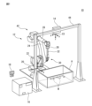
以下、本開示の実施の形態を図面に基づいて詳細に説明する。なお、以下に説明する種々の実施形態において、同様の要素には同じ符号を付し、重複する説明を省略する。まず、図1及び図2を参照して、一実施形態に係るロボットシステム10について説明する。ロボットシステム10は、容器Aにバラ積みにされたワークWをピックアップする作業を行うものであって、ロボット12、視覚センサ14、制御装置16、及び教示装置18を備える。
Hereinafter, embodiments of the present disclosure will be described in detail based on the drawings. In addition, in various embodiments described below, the same reference numerals are given to the same elements, and redundant descriptions are omitted. First, a robot system 10 according to an embodiment will be described with reference to FIGS. 1 and 2. FIG. The robot system 10 performs the work of picking up the works W randomly stacked in the container A, and includes a robot 12 , a visual sensor 14 , a control device 16 and a teaching device 18 .
本実施形態においては、ロボット12は、垂直多関節ロボットであって、ロボットベース20、旋回胴22、下腕部24、上腕部26、手首部28、及びハンド30を有する。ロボットベース20は、作業セルの床の上に固定される。旋回胴22は、鉛直軸周りに回動可能となるようにロボットベース20に設けられている。下腕部24は、水平軸周りに回動可能となるように旋回胴22に設けられ、上腕部26は、下腕部24の先端部に回動可能に設けられている。手首部28は、上腕部26の先端部に回動可能に設けられている。
In this embodiment, the robot 12 is a vertical articulated robot, and has a robot base 20, a swinging trunk 22, a lower arm 24, an upper arm 26, a wrist 28, and a hand 30. A robot base 20 is fixed on the floor of the work cell. The swing barrel 22 is provided on the robot base 20 so as to be rotatable about a vertical axis. The lower arm 24 is provided on the swing barrel 22 so as to be rotatable around the horizontal axis, and the upper arm 26 is rotatably provided at the tip of the lower arm 24 . The wrist portion 28 is rotatably provided at the distal end portion of the upper arm portion 26 .
ロボットベース20、旋回胴22、下腕部24、上腕部26、及び手首部28には、複数のサーボモータ40(図2)がそれぞれ設けられている。サーボモータ40は、制御装置16からの指令に応じて、旋回胴22、下腕部24、上腕部26、及び手首部28を駆動軸周りにそれぞれ回動させ、これによりロボット12を動作させる。なお、本稿においては、ロボットベース20、旋回胴22、下腕部24、上腕部26、及び手首部28を、ロボット12の機構部42として言及する。
A plurality of servo motors 40 (FIG. 2) are provided in the robot base 20, the swing body 22, the lower arm section 24, the upper arm section 26, and the wrist section 28, respectively. The servomotor 40 rotates the swing barrel 22 , the lower arm 24 , the upper arm 26 and the wrist 28 around the drive shafts in response to commands from the control device 16 , thereby operating the robot 12 . In this paper, the robot base 20 , swing body 22 , lower arm section 24 , upper arm section 26 and wrist section 28 are referred to as the mechanical section 42 of the robot 12 .
ハンド30は、手首部28の先端部(いわゆる、手首フランジ)に着脱可能に取り付けられ、ロボット12の機構部42によって移動される。具体的には、図3に示すように、ハンド30は、ハンドアーム32、爪部34及び36、並びに爪部駆動部38を有する。ハンドアーム32は、その基端部が手首部28の先端部に連結されている。
The hand 30 is detachably attached to the tip of the wrist 28 (so-called wrist flange) and moved by the mechanism 42 of the robot 12 . Specifically, as shown in FIG. 3, the hand 30 has a hand arm 32, claw portions 34 and 36, and a claw portion driving portion 38. As shown in FIG. The hand arm 32 is connected at its proximal end to the distal end of the wrist portion 28 .
爪部34及び36は、ハンドアーム32の先端部に開閉可能に設けられている。本実施形態においては、爪部34及び36の各々は、直線状に延びる円柱状の棒部材である。爪部駆動部38は、例えば、空圧式又は油圧式のシリンダ、若しくはサーボモータを有し、制御装置16からの指令に応じて、爪部34及び36を開閉させる。ハンド30は、爪部34及び36を開閉させることで、ワークWを把持したり、解放したりできる。
The claws 34 and 36 are provided at the tip of the hand arm 32 so as to be openable and closable. In the present embodiment, each of the claws 34 and 36 is a cylindrical rod member extending linearly. The pawl driving section 38 has, for example, a pneumatic or hydraulic cylinder or a servomotor, and opens and closes the pawl sections 34 and 36 according to commands from the control device 16 . The hand 30 can grip and release the work W by opening and closing the claws 34 and 36 .
再度、図1及び図2を参照して、視覚センサ14は、ワークWを撮像する。具体的には、視覚センサ14は、保持フレーム44に固定されている。保持フレーム44は、作業セルの床の上に固定されており、視覚センサ14を、容器Aの上方の位置に静止して配置する。
Again, referring to FIGS. 1 and 2, the visual sensor 14 images the workpiece W. FIG. Specifically, the visual sensor 14 is fixed to the holding frame 44 . A holding frame 44 is fixed above the floor of the workcell and places the visual sensor 14 in a stationary position above the container A. As shown in FIG.
本実施形態においては、視覚センサ14は、撮像センサ(CMOS、CCD等)と、該撮像センサへ被写体像を導光する光学レンズ(コリメートレンズ、フォーカスレンズ等)とを有する3次元視覚センサであって、視線方向VLに沿って被写体を撮像するとともに、該被写体像までの距離dを測定するように構成されている。
In this embodiment, the visual sensor 14 is a three-dimensional visual sensor having an imaging sensor (CMOS, CCD, etc.) and an optical lens (collimating lens, focus lens, etc.) for guiding a subject image to the imaging sensor. , an object is imaged along the line-of-sight direction VL, and the distance d to the object image is measured.
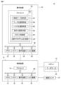
教示装置18は、ロボット12が容器Aにバラ積みにされたワークWをハンド30で把持する動作を教示する。具体的には、教示装置18は、例えば、教示ペンダント又はタブレット型端末装置等の携帯型コンピュータであって、プロセッサ50、メモリ52、I/Oインターフェース54、表示装置56、及び入力装置58を有する。プロセッサ50は、CPU又はGPU等を有し、メモリ52、I/Oインターフェース54、表示装置56、及び入力装置58とバス60を介して通信可能に接続され、これらコンポーネントと通信しつつ、後述する教示機能を実現するための演算処理を行う。
The teaching device 18 teaches the operation of the robot 12 gripping the workpiece W randomly stacked in the container A with the hand 30 . Specifically, the teaching device 18 is, for example, a portable computer such as a teaching pendant or tablet terminal device, and has a processor 50, a memory 52, an I/O interface 54, a display device 56, and an input device 58. . The processor 50 has a CPU, GPU, or the like, and is communicably connected to a memory 52, an I/O interface 54, a display device 56, and an input device 58 via a bus 60. While communicating with these components, Arithmetic processing is performed to realize the teaching function.
メモリ52は、RAM又はROM等を有し、各種データを一時的又は恒久的に記憶する。I/Oインターフェース54は、例えば、イーサネット(登録商標)ポート、USBポート、光ファイバコネクタ、又はHDMI(登録商標)端子を有し、プロセッサ50からの指令の下、外部機器との間でデータを有線又は無線で通信する。
The memory 52 has RAM, ROM, etc., and temporarily or permanently stores various data. The I/O interface 54 has, for example, an Ethernet (registered trademark) port, a USB port, an optical fiber connector, or an HDMI (registered trademark) terminal, and exchanges data with external devices under instructions from the processor 50. Communicate by wire or wirelessly.
表示装置56は、液晶ディスプレイ又は有機ELディスプレイ等を有し、プロセッサ50からの指令の下、各種データを視認可能に表示する。入力装置58は、押しボタン、キーボード、マウス、又はタッチパネル等を有し、オペレータからの入力データを受け付ける。
The display device 56 has a liquid crystal display, an organic EL display, or the like, and visually displays various data under commands from the processor 50 . The input device 58 has push buttons, a keyboard, a mouse, a touch panel, or the like, and receives input data from the operator.
教示装置18は、入力装置58への入力データに応じて、制御装置16を介してロボット12へ指令を送り、該指令に従って該ロボット12をジョグ動作させることができるように構成されている。なお、表示装置56及び入力装置58は、教示装置18の筐体に一体に組み込まれてもよいし、又は、教示装置18の筐体とは別体として該筐体に外付けされてもよい。
The teaching device 18 is configured to be able to send commands to the robot 12 via the control device 16 according to input data to the input device 58, and jog the robot 12 according to the commands. The display device 56 and the input device 58 may be integrated into the housing of the teaching device 18, or may be externally attached to the housing of the teaching device 18 as separate bodies. .
制御装置16は、ロボット12及び視覚センサ14の動作を制御する。具体的には、制御装置16は、プロセッサ70、メモリ72、I/Oインターフェース74、表示装置76、及び入力装置78を有するコンピュータである。プロセッサ70、メモリ72、I/Oインターフェース74、表示装置76、及び入力装置78の構成及び機能は、上述のプロセッサ50、メモリ52、表示装置56、及び入力装置58と同様であるので、重複する説明を省略する。
The control device 16 controls the operations of the robot 12 and the visual sensor 14. Specifically, controller 16 is a computer having processor 70 , memory 72 , I/O interface 74 , display 76 , and input device 78 . The configuration and function of processor 70, memory 72, I/O interface 74, display device 76, and input device 78 are similar to processor 50, memory 52, display device 56, and input device 58 described above, and thus are redundant. Description is omitted.
プロセッサ70は、バス80を介して、メモリ72、I/Oインターフェース74、表示装置76、及び入力装置78に通信可能に接続され、これらコンポーネントと通信しつつ、ロボット12及び視覚センサ14を動作させる機能を実現するための演算処理を行う。教示装置18のI/Oインターフェース54、ロボット12の各サーボモータ40、及び視覚センサ14は、I/Oインターフェース74に接続され、プロセッサ70は、I/Oインターフェース74を通して、これらコンポーネントと通信する。
Processor 70 is communicatively connected to memory 72, I/O interface 74, display device 76, and input device 78 via bus 80 and communicates with these components to operate robot 12 and vision sensor 14. Arithmetic processing is performed to realize functions. The I/O interface 54 of the teacher 18, each servo motor 40 of the robot 12, and the vision sensor 14 are connected to an I/O interface 74 through which the processor 70 communicates with these components.
図1に示すように、ロボット12の機構部42には、ロボット座標系C1が設定される。ロボット座標系C1は、ロボット12がハンド30でワークWを把持する動作を自動制御するための制御座標系Cである。本実施形態においては、ロボット座標系C1は、その原点がロボットベース20の中心に配置され、そのz軸が旋回胴22の回動軸と一致するように、機構部42に対して設定されている。
As shown in FIG. 1, a robot coordinate system C1 is set in the mechanism section 42 of the robot 12. The robot coordinate system C<b>1 is a control coordinate system C for automatically controlling the action of the robot 12 gripping the work W with the hand 30 . In this embodiment, the robot coordinate system C1 is set with respect to the mechanism section 42 such that its origin is located at the center of the robot base 20 and its z-axis coincides with the rotation axis of the swing body 22. there is
一方、ロボット12のハンド30には、図3に示すように、ツール座標系C2が設定される。ツール座標系C2は、制御座標系Cであって、ロボット座標系C1におけるハンド30の位置及び姿勢を規定する。本実施形態においては、ツール座標系C2は、その原点が、爪部34及び36の中間位置に配置され、そのy軸方向が、爪部34及び36の開閉方向と平行であり、そのz軸方向が、各々の爪部34及び36の延在方向と平行になるように、ハンド30に対して設定される。
On the other hand, a tool coordinate system C2 is set for the hand 30 of the robot 12, as shown in FIG. The tool coordinate system C2 is the control coordinate system C and defines the position and orientation of the hand 30 in the robot coordinate system C1. In this embodiment, the tool coordinate system C2 has its origin located at the intermediate position between the claws 34 and 36, its y-axis direction parallel to the opening/closing direction of the claws 34 and 36, and its z-axis The direction is set with respect to the hand 30 so as to be parallel to the extending directions of the respective claws 34 and 36 .
ツール座標系C2とロボット座標系C1との位置関係は既知であり、ツール座標系C2の座標とロボット座標系C1の座標とは、既知の変換行列M1(例えば、同次変換行列)を介して、相互に変換可能となっている。したがって、ロボット座標系C1におけるツール座標系C2の原点位置及び各軸の方向は、ロボット座標系C1の座標(XRT,YRT,ZRT,WRT,PRT,RRT)として表される。ここで、座標(XRT,YRT,ZRT)は、ロボット座標系C1におけるツール座標系C2の原点位置を示し、座標(WRT,PRT,RRT)は、ロボット座標系C1におけるツール座標系C2の各軸の方向(いわゆる、ヨー、ピッチ、ロール)を示している。
The positional relationship between the tool coordinate system C2 and the robot coordinate system C1 is known. , are mutually convertible. Therefore, the origin position and the direction of each axis of the tool coordinate system C2 in the robot coordinate system C1 are expressed as coordinates ( XRT , YRT , ZRT , WRT , PRT , RRT ) of the robot coordinate system C1. . Here, the coordinates ( XRT , YRT , ZRT ) indicate the origin position of the tool coordinate system C2 in the robot coordinate system C1, and the coordinates ( WRT , PRT , RRT ) indicate the tool position in the robot coordinate system C1. The direction of each axis (so-called yaw, pitch, roll) of the coordinate system C2 is shown.
ロボット12の機構部42によってハンド30を所定の位置及び姿勢に位置決めするとき、制御装置16のプロセッサ70は、まず、該所定の位置及び姿勢を表すツール座標系C2をロボット座標系C1に設定する。そして、プロセッサ70は、設定したツール座標系C2によって規定される位置及び姿勢にハンド30を配置させるように、各サーボモータ40への指令を生成し、該指令に応じて機構部42を動作させることで、ハンド30を移動させる。こうして、プロセッサ70は、ロボット座標系C1において、機構部42の動作によってハンド30を所定の位置及び姿勢に位置決めできる。
When positioning the hand 30 at a predetermined position and orientation by the mechanism section 42 of the robot 12, the processor 70 of the control device 16 first sets the tool coordinate system C2 representing the predetermined position and orientation to the robot coordinate system C1. . Then, the processor 70 generates a command to each servo motor 40 so as to place the hand 30 in the position and orientation defined by the set tool coordinate system C2, and operates the mechanism section 42 according to the command. By doing so, the hand 30 is moved. In this way, the processor 70 can position the hand 30 at a predetermined position and posture in the robot coordinate system C1 by operating the mechanism section 42 .
図1に示すように、視覚センサ14には、センサ座標系C3が設定される。センサ座標系C3は、制御座標系Cであって、ロボット座標系C1における視覚センサ14の位置及び姿勢(つまり、視線方向VL)を規定するとともに、該視覚センサ14が撮像した画像データ(又は、撮像センサ)の各画素の座標を規定する。本実施形態においては、センサ座標系C3は、その原点が撮像センサの中心に配置され、そのz軸方向が視覚センサ14の視線方向VLと一致するように、視覚センサ14に対して設定されている。
As shown in FIG. 1, the visual sensor 14 is set with a sensor coordinate system C3. The sensor coordinate system C3 is the control coordinate system C, defines the position and orientation (that is, line-of-sight direction VL) of the visual sensor 14 in the robot coordinate system C1, and stores image data captured by the visual sensor 14 (or It defines the coordinates of each pixel of the image sensor). In this embodiment, the sensor coordinate system C3 is set with respect to the visual sensor 14 such that its origin is located at the center of the imaging sensor and its z-axis direction coincides with the line-of-sight direction VL of the visual sensor 14. there is
ここで、本実施形態においては、視覚センサ14は、保持フレーム44によって、ロボット座標系C1の既知の位置に配置されている。より具体的には、センサ座標系C3とロボット座標系C1との位置関係は、キャリブレーションにより既知となっており、センサ座標系C3の座標とロボット座標系C1の座標とは、既知の変換行列M2(例えば、同次変換行列)を介して、相互に変換可能となっている。こうして、ロボット座標系C1における視覚センサ14の位置及び姿勢(つまり、センサ座標系C3の原点位置及び各軸の方向)が既知となっている。
Here, in this embodiment, the visual sensor 14 is arranged at a known position in the robot coordinate system C1 by the holding frame 44. More specifically, the positional relationship between the sensor coordinate system C3 and the robot coordinate system C1 is already known by calibration, and the coordinates of the sensor coordinate system C3 and the coordinates of the robot coordinate system C1 are obtained by using a known transformation matrix They are mutually transformable via M2 (for example, homogeneous transformation matrix). Thus, the position and orientation of the visual sensor 14 in the robot coordinate system C1 (that is, the origin position and the direction of each axis of the sensor coordinate system C3) are known.
実際の作業ラインにおいて、制御装置16のプロセッサ70は、容器A内にバラ積みされたワークWを視覚センサ14で撮像し、撮像された画像データIDに基づいて、ロボット12にハンド30でワークWを把持させて容器Aからピックアップする動作を実行する。図4に、ワークWの一例を示す。
In an actual work line, the processor 70 of the control device 16 uses the visual sensor 14 to image the workpieces W randomly stacked in the container A, and based on the captured image data ID, moves the workpieces W to the robot 12 with the hand 30. is gripped and picked up from the container A. An example of the workpiece W is shown in FIG.
図4に示す例では、ワークWは、例えば自動車用のコンロッドであって、シャフト部W1、大リング部W2、及び小リング部W3を有する。シャフト部W1は、軸線Bに沿って真直ぐに延在している。大リング部W2は、シャフト部W1の一端に固設され、貫通孔H1を有する。一方、小リング部W3は、シャフト部W1の他端に固設され、貫通孔H2を有する。
In the example shown in FIG. 4, the work W is, for example, a connecting rod for an automobile, and has a shaft portion W1, a large ring portion W2, and a small ring portion W3. The shaft portion W1 extends straight along the axis B. As shown in FIG. The large ring portion W2 is fixed to one end of the shaft portion W1 and has a through hole H1. On the other hand, the small ring portion W3 is fixed to the other end of the shaft portion W1 and has a through hole H2.
ロボット12がハンド30でワークWを把持する動作を実行するために、該ワークWに、ワーク座標系C4が設定される。ワーク座標系C4は、制御座標系Cであって、ロボット座標系C1におけるワークWの位置及び姿勢を規定する。本実施形態においては、ワーク座標系C4は、その原点がシャフト部W1の中心に配置され、そのy軸が、軸線Bと平行であり(又は一致し)、そのz軸が、貫通孔H1及びH2の中心軸と平行となるように、ワークWに対して設定される。
In order for the robot 12 to grip the work W with the hand 30, a work coordinate system C4 is set for the work W. The work coordinate system C4 is the control coordinate system C and defines the position and orientation of the work W in the robot coordinate system C1. In this embodiment, the work coordinate system C4 has its origin located at the center of the shaft portion W1, its y-axis parallel to (or coinciding with) the axis B, and its z-axis extending through the through holes H1 and It is set with respect to the work W so as to be parallel to the central axis of H2.
図5に、ロボット12がハンド30でワークWを把持した状態の一例を示す。図5に示す例では、ハンド30は、その爪部34及び36を貫通孔H1に挿入した状態で開くことにより、ワークWの大リング部W2を該爪部34及び36で把持している。図5に示すようにワークWを把持する動作をロボット12に実行させるためには、ロボット12がハンド30でワークWを把持する位置及び姿勢を教示する必要がある。
FIG. 5 shows an example of a state in which the robot 12 grips the workpiece W with the hand 30. In the example shown in FIG. 5, the hand 30 grips the large ring portion W2 of the work W with the claw portions 34 and 36 by opening the claw portions 34 and 36 while the claw portions 34 and 36 are inserted into the through hole H1. In order to cause the robot 12 to perform the action of gripping the work W as shown in FIG.
以下、ロボットシステム10においてロボット12にワークWを把持する動作を教示する方法について説明する。まず、オペレータは、ロボット12のハンド30に、ワークWを、教示したい把持位置で把持させる。例えば、オペレータは、教示装置18を操作してロボット12をジョグ動作することで、ワークWをハンド30で把持させる。
A method of teaching the robot 12 to grip the workpiece W in the robot system 10 will be described below. First, the operator causes the hand 30 of the robot 12 to grip the workpiece W at a desired gripping position. For example, the operator operates the teaching device 18 to jog the robot 12 to grip the workpiece W with the hand 30 .
より具体的には、オペレータは、教示装置18の表示装置56を視認しつつ、入力装置58を操作して、ロボット12の機構部42によりハンド30を移動させ、閉状態の爪部34及び36を、予め定められた保管場所に配置されているワークWの貫通孔H1に挿入する。次いで、オペレータは、入力装置58を操作して爪部34及び36を開状態とし、該爪部34及び36を貫通孔H1の内壁面に押し当てることで、該ワークWを把持する。
More specifically, while viewing the display device 56 of the teaching device 18, the operator operates the input device 58 to move the hand 30 by the mechanical portion 42 of the robot 12, thereby opening the claw portions 34 and 36 in the closed state. is inserted into the through hole H1 of the work W arranged in a predetermined storage place. Next, the operator operates the input device 58 to open the claw portions 34 and 36, and presses the claw portions 34 and 36 against the inner wall surface of the through hole H1 to grip the workpiece W.
このとき、オペレータは、ハンド30にワークWを、教示したい把持位置で把持させるように、ロボット12をジョグ動作させる。以下、オペレータが、ハンド30でワークWを、図5に示す把持位置で把持させた場合について、説明する。次いで、オペレータは、入力装置58を操作してロボット12をジョグ動作し、ハンド30が把持するワークWを視覚センサ14の視野内に収めるように、ロボット12の機構部42によってハンド30を移動させる。
At this time, the operator jogs the robot 12 so that the hand 30 grips the workpiece W at the desired gripping position. A case where the operator grips the workpiece W with the hand 30 at the gripping position shown in FIG. 5 will be described below. Next, the operator operates the input device 58 to jog the robot 12, and moves the hand 30 by the mechanical section 42 of the robot 12 so that the work W gripped by the hand 30 is within the visual field of the visual sensor 14. .
次いで、オペレータは、入力装置58を操作して、視覚センサ14にハンド30が把持しているワークWを撮像させる。視覚センサ14は、制御装置16を介して教示装置18から撮像指令を受け付け、ワークWの画像データID1を撮像する。画像データID1の一例を、図6に示す。
Next, the operator operates the input device 58 to cause the visual sensor 14 to image the work W gripped by the hand 30 . The visual sensor 14 receives an imaging command from the teaching device 18 via the control device 16 and images the image data ID 1 of the workpiece W. FIG. An example of image data ID 1 is shown in FIG.
図6に示す例では、画像データID1に、ワークW及びハンド30の視覚的特徴(エッジ、孔、又は頂点等)が3次元点群として表示されている。3次元点群を構成する各点は、上述の距離dの情報を有しており、センサ座標系C3の3次元座標(XS,YS,ZS)として表すことができるようになっている。すなわち、本実施形態においては、画像データID1は、3次元画像データである。
In the example shown in FIG. 6, visual features (edges, holes, vertices, etc.) of the workpiece W and the hand 30 are displayed as a three-dimensional point group in the image data ID 1 . Each point constituting the three-dimensional point group has the information of the distance d described above, and can be expressed as three-dimensional coordinates (X S , Y S , Z S ) in the sensor coordinate system C3. there is That is, in this embodiment, image data ID 1 is three-dimensional image data.
教示装置18のプロセッサ50は、制御装置16、及びI/Oインターフェース54を通して、視覚センサ14から画像データID1を取得する。このように、本実施形態においては、プロセッサ50は、ロボット12がハンド30でワークWを把持しているときに視覚センサ14が該ワークWを撮像した画像データIDを取得する画像データ取得部82(図2)として機能する。
Processor 50 of teaching device 18 acquires image data ID 1 from visual sensor 14 through controller 16 and I/O interface 54 . As described above, in the present embodiment, the processor 50 includes the image data acquisition unit 82 that acquires the image data ID of the work W imaged by the visual sensor 14 while the robot 12 is gripping the work W with the hand 30. (Fig. 2).
次いで、プロセッサ50は、画像データID1に基づいて、視覚センサ14が該画像データID1を撮像したときのロボット座標系C1におけるワークWの位置及び姿勢を示すワーク位置データWPD1を取得する。具体的には、プロセッサ50は、まず、ワークWをモデル化したワークモデルWMを取得する。このワークモデルWMは、例えば3次元CADモデルであって、メモリ52に予め格納される。
Next, based on the image data ID 1 , the processor 50 acquires work position data WPD 1 indicating the position and orientation of the work W in the robot coordinate system C1 when the visual sensor 14 captured the image data ID 1 . Specifically, the processor 50 first acquires a work model WM that models the work W. As shown in FIG. This work model WM is, for example, a three-dimensional CAD model and is stored in the memory 52 in advance.
プロセッサ50は、予め定められたパターンマッチングパラメータを用いて、画像データID1に写るワークWの3次元点群画像を解析し、ワークモデルWMを、該画像データID1に写るワークWに一致させるように、該画像データID1内に模擬的に配置する。図7に、画像データID1に模擬的に配置されたワークモデルWMを示す。なお、図7においては、理解の容易のために、ハンド30の画像を省略している。
Using predetermined pattern matching parameters, the processor 50 analyzes the three-dimensional point cloud image of the workpiece W captured in the image data ID 1 , and matches the workpiece model WM with the workpiece W captured in the image data ID 1 . are arranged in the image data ID 1 in a simulated manner. FIG. 7 shows the work model WM arranged in image data ID 1 in a simulated manner. Note that the image of the hand 30 is omitted in FIG. 7 for easy understanding.
そして、プロセッサ50は、画像データID1に配置したワークモデルWMに対し、図4に示す位置関係でワーク座標系C4を設定する。このワーク座標系C4は、画像データID1に写るワークWの、センサ座標系C3における位置及び姿勢を示し、センサ座標系C3の座標QSW_1(XSW_1,YSW_1,ZSW_1,WSW_1,PSW_1,RSW_1)(第1座標)として表される。
Then, the processor 50 sets the work coordinate system C4 with the positional relationship shown in FIG. 4 for the work model WM arranged in the image data ID 1 . This work coordinate system C4 indicates the position and orientation of the work W reflected in the image data ID 1 in the sensor coordinate system C3, and the coordinates Q SW_1 (X SW_1 , Y SW_1 , Z SW_1 , W SW_1 , P SW_1 , R SW_1 ) (first coordinates).
ここで、座標(XSW_1,YSW_1,ZSW_1)は、センサ座標系C3におけるワーク座標系C4の原点位置を示し、座標(WSW_1,PSW_1,RSW_1)は、センサ座標系C3におけるワーク座標系C4の各軸の方向(いわゆる、ヨー、ピッチ、ロール)を示している。プロセッサ50は、画像データID1に写るワークWのセンサ座標系C3における位置及び姿勢を示すデータとして、センサ座標系C3におけるワーク座標系C4の座標QSW_1を取得する。
Here, the coordinates (X SW_1 , Y SW_1 , Z SW_1 ) indicate the origin position of the work coordinate system C4 in the sensor coordinate system C3, and the coordinates (W SW_1 , P SW_1 , R SW_1 ) indicate the work position in the sensor coordinate system C3. The direction of each axis (so-called yaw, pitch, roll) of the coordinate system C4 is shown. The processor 50 acquires the coordinates QSW_1 of the workpiece coordinate system C4 in the sensor coordinate system C3 as data indicating the position and orientation of the workpiece W captured in the image data ID 1 in the sensor coordinate system C3.
次いで、プロセッサ50は、上述の変換行列M2を用いて、取得した座標QSW_1をロボット座標系C1に変換することで、図7に示すワーク座標系C4の、ロボット座標系C1における座標QRW_1(XRW_1,YRW_1,ZRW_1,WRW_1,PRW_1,RRW_1)(第2座標)を取得する。この座標QRW_1は、画像データID1に写るワークW(具体的には、図7中のワークモデルWM)の、ロボット座標系C1における位置及び姿勢を示すデータである。
Next, the processor 50 transforms the obtained coordinates Q SW_1 into the robot coordinate system C1 using the transformation matrix M2 described above, so that the coordinates Q RW_1 ( XRW_1 , YRW_1 , ZRW_1 , WRW_1 , PRW_1 , RRW_1 ) (second coordinates). This coordinate QRW_1 is data indicating the position and orientation of the workpiece W (specifically, the workpiece model WM in FIG. 7) captured in the image data ID 1 in the robot coordinate system C1.
プロセッサ50は、この座標QRW_1を、ワーク位置データWPD1として取得する。このように、本実施形態においては、プロセッサ50は、画像データID1に基づいてワーク位置データWPD1(座標QRW_1)を取得するワーク位置取得部84(図2)として機能する。
The processor 50 acquires this coordinate QRW_1 as work position data WPD1 . Thus, in this embodiment, the processor 50 functions as the work position acquisition unit 84 (FIG. 2) that acquires the work position data WPD 1 (coordinates Q RW — 1 ) based on the image data ID 1 .
一方、プロセッサ50は、視覚センサ14が画像データID1を撮像したときのロボット座標系C1におけるハンド30の位置及び姿勢を示すハンド位置データHPD1を取得する。具体的には、プロセッサ50は、視覚センサ14が画像データID1を撮像したときの、ロボット座標系C1におけるツール座標系C2の座標QRT_1(XRT_1,YRT_1,ZRT_1,WRT_1,PRT_1,RRT_1)(第3座標)を、ハンド位置データHPD1として取得する。このように、本実施形態においては、プロセッサ50は、ハンド位置データHPD1(座標QRT_1)を取得するハンド位置取得部86(図2)として機能する。
On the other hand, the processor 50 acquires hand position data HPD1 indicating the position and orientation of the hand 30 in the robot coordinate system C1 when the visual sensor 14 captured the image data ID1 . Specifically, the processor 50 calculates the coordinates Q RT — 1 (X RT — 1 , Y RT — 1 , Z RT — 1 , W RT — 1 , P RT — 1 , R RT — 1 ) (third coordinates) are acquired as hand position data HPD 1 . Thus, in this embodiment, the processor 50 functions as the hand position acquisition unit 86 (FIG. 2) that acquires the hand position data HPD 1 (coordinates Q RT — 1 ).
そして、プロセッサ50は、取得したワーク位置データWPD1及びハンド位置データHPD1に基づいて、視覚センサ14が画像データID1を撮像したときの、制御座標系Cにおけるハンド30とワークWとの位置関係を示す教示位置データTPD1を取得する。
Based on the obtained work position data WPD 1 and hand position data HPD 1 , the processor 50 determines the positions of the hand 30 and the work W in the control coordinate system C when the visual sensor 14 captured the image data ID 1 . Acquire teaching position data TPD 1 that indicates the relationship.
一例として、プロセッサ50は、ワーク位置データWPD1として取得した座標QRW_1と、ハンド位置データHPD1として取得した座標QRT_1とに基づいて、ワーク位置データWPD1としての座標QRW_1を、ハンド位置データHPD1としての座標QRT_1で表されるツール座標系C2の座標に変換する。ここで、座標QRW_1及びQRT_1によって、ロボット座標系C1におけるツール座標系C2とワーク座標系C4との位置関係が既知となっているので、ロボット座標系C1におけるワーク座標系C4の座標QRW_1をツール座標系C2に変換できる。
As an example, the processor 50 converts the coordinates Q RW_1 as the work position data WPD 1 to the hand position data WPD 1 based on the coordinates Q RW_1 obtained as the work position data WPD 1 and the coordinates Q RT_1 obtained as the hand position data HPD 1 . Convert to the coordinates of the tool coordinate system C2 represented by the coordinates QRT_1 as the data HPD1 . Here, since the positional relationship between the tool coordinate system C2 and the work coordinate system C4 in the robot coordinate system C1 is known by the coordinates Q RW_1 and Q RT_1 , the coordinate Q RW_1 of the work coordinate system C4 in the robot coordinate system C1 is can be transformed into the tool coordinate system C2.
この座標変換によって、プロセッサ50は、視覚センサ14が画像データID1を撮像したときの、ツール座標系C2におけるワーク座標系C4の座標QTW_1(XTW_1,YTW_1,ZTW_1,WTW_1,PTW_1,RTW_1)を取得する。この座標QTW_1は、視覚センサ14が画像データID1を撮像したときの、ハンド30(つまり、ツール座標系C2)に対する、ワークWの位置及び姿勢(つまり、ワーク座標系C4の原点位置及び各軸の方向)を示すデータである。プロセッサ50は、この座標QTW_1を、教示位置データTPD1として取得する。
With this coordinate transformation, the processor 50 determines the coordinates Q TW_1 (X TW_1 , Y TW_1 , Z TW_1 , W TW_1 , P TW_1 , RTW_1 ). This coordinate QTW_1 is the position and orientation of the work W (that is, the origin position of the work coordinate system C4 and each This is data indicating the direction of the axis). The processor 50 acquires this coordinate Q TW_1 as the teaching position data TPD1 .
他の例として、プロセッサ50は、ワーク位置データWPD1としての座標QRW_1と、ハンド位置データHPD1としての座標QRT_1とに基づいて、ハンド位置データHPD1としての座標QRT_1を、ワーク位置データWPD1としての座標QRW_1で表されるワーク座標系C4の座標に変換する。これにより、プロセッサ50は、視覚センサ14が画像データID1を撮像したときの、ワーク座標系C4におけるツール座標系C2の座標QWT_1(XWT_1,YWT_1,ZWT_1,WWT_1,PWT_1,RWT_1)を取得する。
As another example, the processor 50 converts the coordinates Q RT_1 as the hand position data HPD 1 to the work position based on the coordinates Q RW_1 as the work position data WPD 1 and the coordinates Q RT_1 as the hand position data HPD 1 . The coordinates are converted into the coordinates of the workpiece coordinate system C4 represented by the coordinates QRW_1 as the data WPD1 . As a result, the processor 50 calculates the coordinates Q WT_1 (X WT_1 , Y WT_1 , Z WT_1 , W WT_1 , P WT_1 , W WT_1 , P WT_1 , of the tool coordinate system C2 in the work coordinate system C4 when the visual sensor 14 captured the image data ID 1 . RWT_1 ).
この座標QWT_1は、視覚センサ14が画像データID1を撮像したときの、ワークW(つまり、ワーク座標系C4)に対する、ハンド30の位置及び姿勢(つまり、ツール座標系C2の原点位置及び各軸の方向)を示すデータである。プロセッサ50は、この座標QWT_1を、教示位置データTPD1として取得する。
This coordinate QWT_1 is the position and orientation of the hand 30 (that is, the origin position of the tool coordinate system C2 and each This is data indicating the direction of the axis). The processor 50 acquires this coordinate QWT_1 as the teaching position data TPD1 .
このように、本実施形態においては、プロセッサ50は、ワーク位置データWPD1及びハンド位置データHPD1に基づいて、視覚センサ14が画像データID1を撮像したときの、制御座標系C(ツール座標系C2、ワーク座標系C4)におけるハンド30とワークWとの位置関係を示す教示位置データTPD1(座標QTW_1、座標QWT_1)を取得する教示位置取得部88(図1)として機能する。
Thus, in this embodiment , the processor 50 controls the control coordinate system C ( tool coordinates It functions as a teaching position acquisition unit 88 (FIG. 1) that acquires teaching position data TPD1 (coordinates QTW_1 , coordinates QWT_1 ) indicating the positional relationship between the hand 30 and the work W in the system C2 and the work coordinate system C4).
教示位置データTPD1を取得した後、オペレータは、入力装置58を操作して、ロボット12の機構部42の動作により、ワークWを把持した状態でハンド30の姿勢を変化させる。例えば、オペレータは、入力装置58を操作して、ハンド30を、この時点でロボット座標系C1に設定されているツール座標系C2のx軸、y軸、又はz軸周りに所定の角度θ(例えば、10°)だけ回転させるための入力データを入力する。
After acquiring the teaching position data TPD 1 , the operator operates the input device 58 to change the posture of the hand 30 while gripping the workpiece W by operating the mechanism section 42 of the robot 12 . For example, the operator operates the input device 58 to move the hand 30 at a predetermined angle θ ( For example, input data for rotating by 10°.
代替的には、オペレータは、ハンド30を、この時点でロボット座標系C1に設定されているワーク座標系C4のx軸、y軸、又はz軸周りに所定の角度θだけ回転させるための入力データを入力してもよい。例えば、ワーク座標系C4のy軸がワークWの軸線Bと一致する場合、オペレータは、ワーク座標系C4のy軸(つまり、軸線B)の周りにハンド30を回転させる入力データを入力してもよい。
Alternatively, the operator inputs an input to rotate the hand 30 by a predetermined angle θ about the x-axis, y-axis, or z-axis of the work coordinate system C4 set in the robot coordinate system C1 at this time. You may enter data. For example, when the y-axis of the work coordinate system C4 coincides with the axis B of the work W, the operator inputs input data to rotate the hand 30 around the y-axis (that is, the axis B) of the work coordinate system C4. good too.
プロセッサ50は、オペレータからの入力データに応じて、制御装置16を介してロボット12のサーボモータ40に指令を送り、ワークWを把持しているハンド30の姿勢を変化させるように機構部42を動作させる。このように、本実施形態においては、プロセッサ50は、ハンド30の姿勢を変化させるようにロボット12を動作させるロボット制御部90(図2)として機能する。
The processor 50 sends a command to the servo motor 40 of the robot 12 via the control device 16 according to the input data from the operator, and operates the mechanism section 42 so as to change the posture of the hand 30 gripping the work W. make it work. Thus, in this embodiment, the processor 50 functions as a robot control section 90 ( FIG. 2 ) that operates the robot 12 so as to change the posture of the hand 30 .
ハンド30の姿勢を変化させたとき、オペレータは、入力装置58を操作して視覚センサ14にハンド30が把持しているワークWを撮像させ、プロセッサ50は、画像データ取得部82として機能して、ワークWの画像データID2を取得する。そして、プロセッサ50は、ワーク位置取得部84として機能し、上述した方法により、画像データID2にワークモデルWMを適用することで、センサ座標系C3におけるワーク座標系C4の座標QSW_2(XSW_2,YSW_2,ZSW_2,WSW_2,PSW_2,RSW_2)(第1座標)を取得する。
When the posture of the hand 30 is changed, the operator operates the input device 58 to cause the visual sensor 14 to image the work W gripped by the hand 30, and the processor 50 functions as an image data acquisition unit 82. , the image data ID 2 of the workpiece W is obtained. Then, the processor 50 functions as the work position acquisition unit 84 and applies the work model WM to the image data ID 2 by the method described above, thereby obtaining the coordinates Q SW_2 (X SW_2 ) of the work coordinate system C4 in the sensor coordinate system C3. , Y SW — 2 , Z SW — 2 , W SW — 2 , P SW — 2 , R SW — 2 ) (first coordinates).
次いで、プロセッサ50は、ワーク位置取得部84として機能し、上述した方法により、取得した座標QSW_2をロボット座標系C1に変換することで、画像データID2の撮像時のワーク位置データWPD2として、ロボット座標系C1におけるワーク座標系C4の座標QRW_2(XRW_2,YRW_2,ZRW_2,WRW_2,PRW_2,RRW_2)(第2座標)を取得する。
Next, the processor 50 functions as the work position acquisition unit 84, and converts the acquired coordinates Q SW_2 into the robot coordinate system C1 by the above-described method, thereby obtaining work position data WPD 2 at the time of imaging of the image data ID 2 . , coordinates QRW_2 ( XRW_2 , YRW_2 , ZRW_2 , WRW_2 , PRW_2 , RRW_2 ) (second coordinates) of the workpiece coordinate system C4 in the robot coordinate system C1.
また、プロセッサ50は、ハンド位置取得部86として機能し、上述した方法により、画像データID2の撮像時のハンド位置データHPD2として、ロボット座標系C1におけるツール座標系C2の座標QRT_2(XRT_2,YRT_2,ZRT_2,WRT_2,PRT_2,RRT_2)(第3座標)を取得する。
In addition , the processor 50 functions as the hand position acquisition unit 86 , and the coordinates Q RT_2 (X RT_2 , YRT_2 , ZRT_2 , WRT_2 , PRT_2 , RRT_2 ) (third coordinates).
そして、プロセッサ50は、教示位置取得部88として機能し、上述した方法により、画像データID2の撮像時の教示位置データTPD2として、ツール座標系C2におけるワーク座標系C4の座標QTW_2(XTW_2,YTW_2,ZTW_2,WTW_2,PTW_2,RTW_2)、又は、ワーク座標系C4におけるツール座標系C2の座標QWT_2(XWT_2,YWT_2,ZWT_2,WWT_2,PWT_2,RWT_2)を取得する。
Then , the processor 50 functions as the teaching position acquisition unit 88 and acquires the coordinates Q TW_2 (X TW_2 , Y TW_2 , Z TW_2 , W TW_2 , P TW_2 , R TW_2 ), or coordinates Q WT_2 (X WT_2 , Y WT_2 , Z WT_2 , W WT_2 , P WT_2 , R WT_2 ).
このようにして、オペレータは、入力装置58を操作してハンド30の姿勢を繰り返し変化させ、視覚センサ14は、ハンド30の姿勢が変化される毎に、該ハンド30が把持するワークWを撮像し、プロセッサ50は、画像データ取得部82として機能して、視覚センサ14が撮像した複数の画像データIDn(n=1,2,3,・・・)を取得する。
In this manner, the operator operates the input device 58 to repeatedly change the posture of the hand 30, and the visual sensor 14 captures the workpiece W gripped by the hand 30 each time the posture of the hand 30 is changed. The processor 50 functions as an image data acquisition unit 82 and acquires a plurality of image data ID n (n=1, 2, 3, . . . ) captured by the visual sensor 14 .
そして、プロセッサ50は、ワーク位置取得部84として機能して、上述した方法により、各々の画像データIDnが撮像されたときのワーク位置データWPDn:座標QRW_n(XRW_n,YRW_n,ZRW_n,WRW_n,PRW_n,RRW_n)をそれぞれ取得するとともに、ハンド位置取得部86として機能して、上述した方法により、各々の画像データIDnが撮像されたときのハンド位置データHPDn:座標QRT_n(XRT_n,YRT_n,ZRT_n,WRT_n,PRT_n,RRT_n)をそれぞれ取得する。
Then, the processor 50 functions as a work position acquisition unit 84 and uses the above-described method to obtain work position data WPD n when each image data ID n is captured: coordinates Q RW — n (X RW — n , Y RW — n , Z RW_n , W RW_n , P RW_n , R RW_n ), and functioning as the hand position acquisition unit 86, the hand position data HPD n when each image data ID n is captured by the method described above: Obtain the coordinates QRT_n ( XRT_n , YRT_n , ZRT_n , WRT_n , PRT_n , RRT_n ) respectively.
そして、プロセッサ50は、教示位置取得部88として機能して、上述した方法により、取得した各々のワーク位置データWPDn(座標QRW_n)と、各々のハンド位置データHPDn(座標QRT_n)とに基づいて、各々の画像データIDnが撮像されたときの教示位置データTPDn:座標QTW_n(XTW_n,YTW_n,ZTW_n,WTW_n,PTW_n,RTW_n)、又は、座標QWT_n(XWT_n,YWT_n,ZWT_n,WWT_n,PWT_n,RWT_n)を、それぞれ取得する。こうして、プロセッサ50は、ハンド30及びワークWの様々な姿勢に対応する、複数の教示位置データTPDnを取得できる。
Then, the processor 50 functions as a teaching position acquiring unit 88, and acquires each workpiece position data WPD n (coordinates Q RW_n ) and each hand position data HPD n (coordinates Q RT_n ) by the method described above. Taught position data TPD n when each image data ID n is imaged based on ( XWT_n , YWT_n , ZWT_n , WWT_n , PWT_n , RWT_n ) are obtained respectively. Thus, the processor 50 can acquire a plurality of teaching position data TPD n corresponding to various postures of the hand 30 and the workpiece W.
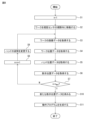
次いで、プロセッサ50は、教示位置取得部88として機能して、取得した複数の教示位置データTPDnに基づいて、ロボット12にワークWをハンド30で実際に把持させる動作に用いられる新たな教示位置データTPD0を求める。以下、プロセッサ50が、教示位置データTPDnとして、ツール座標系C2の座標QTW_n(XTW_n,YTW_n,ZTW_n,WTW_n,PTW_n,RTW_n)を取得した場合において、新たな教示位置データTPD0を求める方法について説明する。
Next, the processor 50 functions as the teaching position acquiring unit 88, and based on the acquired plurality of teaching position data TPD n , new teaching positions to be used for the operation of causing the robot 12 to actually grip the workpiece W with the hand 30. Obtain data TPD 0 . Hereinafter, when the processor 50 acquires the coordinates QTW_n ( XTW_n , YTW_n , ZTW_n , WTW_n , PTW_n , RTW_n ) of the tool coordinate system C2 as the teaching position data TPDn , a new teaching position A method for obtaining data TPD 0 will be described.
まず、プロセッサ50は、複数の座標QTW_nの各々に関し、予め定めた許容範囲外の座標を除外する処理PR1を行う。具体的には、プロセッサ50は、座標QTW_nのうち、位置を表す座標(XTW_n,YTW_n,ZTW_n)について、許容範囲外の座標を除外する処理PR1を行う。
First, the processor 50 performs processing PR1 for excluding coordinates outside a predetermined allowable range for each of the plurality of coordinates Q TW_n . Specifically, the processor 50 performs a process PR1 of excluding coordinates outside the allowable range for the coordinates ( XTW_n , YTW_n , ZTW_n ) representing the position among the coordinates QTW_n .
一例として、プロセッサ50は、ツール座標系C2の原点からの距離Δnを、Δn=(XTW_n
2+YTW_n
2+ZTW_n
2)1/2なる式から求める。そして、プロセッサ50は、求めた距離Δnが、予め定めた許容範囲[Δth1,Δth2]内にあるか否かを判定し、距離Δnが許容範囲[Δth1,Δth2]内である(すなわち、Δth1≦Δn≦Δth2)場合は、取得した座標QTW_nを、有効座標グループGRPとしてメモリ52に登録する一方、距離Δnが許容範囲[Δth1,Δth2]外である(すなわち、Δn<Δth1、又は、Δth2<Δn)場合は、取得した座標QTW_nを、有効座標グループGRPから除外(又は、メモリ52から削除)する。
As an example, the processor 50 obtains the distance Δn from the origin of the tool coordinate system C2 from the formula Δn =(X TW_n 2 +Y TW_n 2 +Z TW_n 2 ) 1/2 . Then, the processor 50 determines whether or not the obtained distance Δn is within a predetermined allowable range [Δ th1 , Δ th2 ], and determines whether the distance Δ n is within the allowable range [Δ th1 , Δ th2 ]. (that is, Δ th1 ≤ Δ n ≤ Δ th2 ), the obtained coordinates Q TW_n are registered in the memory 52 as a valid coordinate group GRP, while the distance Δ n is outside the allowable range [Δ th1 , Δ th2 ]. If yes (ie, Δ n <Δ th1 or Δ th2 <Δ n ), the acquired coordinate Q TW_n is excluded from the valid coordinate group GRP (or deleted from memory 52).
他の例として、プロセッサ50は、座標QTW_n(XTW_n,YTW_n,ZTW_n)の平均の座標QTW_AV(XTW_AV,YTW_AV,ZTW_AV)を求める。具体的には、プロセッサ50は、XTW_AV=1/n・Σ(XTW_n)、YTW_AV=1/n・Σ(YTW_n)、及び、ZTW_AV=1/n・Σ(ZTW_n)なる式から、平均の座標QTW_AV(XTW_AV,YTW_AV,ZTW_AV)を求める。
As another example, the processor 50 determines the average coordinates QTW_AV ( XTW_AV , YTW_AV , ZTW_AV ) of the coordinates QTW_n ( XTW_n , YTW_n , ZTW_n ). Specifically, the processor 50 sets X TW_AV =1/n·Σ(X TW_n ), Y TW_AV =1/n·Σ(Y TW_n ), and Z TW_AV =1/n·Σ(Z TW_n ). An average coordinate QTW_AV ( XTW_AV , YTW_AV , ZTW_AV ) is obtained from the formula.
また、プロセッサ50は、座標QTW_n(XTW_n,YTW_n,ZTW_n)の標準偏差σX、σY及びσZをそれぞれ求める。例えば、プロセッサ50は、σX=(1/n・Σ{XTW_n-XTW_AV})1/2、σY=(1/n・Σ{YTW_n-YTW_AV})1/2、σZ=(1/n・Σ{ZTW_n-ZTW_AV})1/2なる式から求める。
The processor 50 also determines the standard deviations σ X , σ Y and σ Z of the coordinates Q TW_n (X TW_n , Y TW_n , Z TW_n ), respectively. For example, the processor 50 calculates σ X =(1/n·Σ{X TW_n −X TW_AV }) 1/2 , σ Y =(1/n·Σ{Y TW_n −Y TW_AV }) 1/2 , σ Z =(1/n·Σ{Z TW_n -Z TW_AV }) 1/2 .
そして、プロセッサ50は、座標QTW_nにおける座標XTW_n、YTW_n、及びZTW_nの各々に対し、許容範囲を、求めた平均及び標準偏差σと、予め定めた係数α(例えば、αは、正の整数)とを用いて、[XTW_AV-ασX,XTW_AV+ασX](つまり、XTW_AV-ασX≦XTW_n≦XTW_AV+ασX)、[YTW_AV-ασY,YTW_AV+ασY](つまり、YTW_AV-ασY≦YTW_n≦YTW_AV+ασY)、及び、[ZTW_AV-ασZ,ZTW_AV+ασZ](つまり、ZTW_AV-ασZ≦ZTW_n≦ZTW_AV+ασZ)として定める。
Then, the processor 50 calculates the allowable range for each of the coordinates X TW_n , Y TW_n , and Z TW_n in the coordinates Q TW_n as the calculated mean and standard deviation σ and a predetermined coefficient α (for example, α is a positive using [X TW_AV - ασ X , X TW_AV + ασ X ] (that is, X TW_AV - ασ X ≤ X TW_n ≤ X TW_AV + ασ X ), [Y TW_AV - ασ Y , Y TW_AV + ασ Y ] (that is, Y TW_AV − ασ Y ≤ Y TW_n ≤ Y TW_AV + ασ Y ) and [Z TW_AV − ασ Z , Z TW_AV + ασ Z ] (that is, Z TW_AV − ασ Z ≤ Z TW_n ≤ Z TW_AV + ασ Z ). stipulate.
プロセッサ50は、座標XTWが許容範囲[XTW_AV-σX,XTW_AV+σX]内であるか否か、座標YTW_nが許容範囲[YTW_AV-σY,YTW_AV+σY]内であるか否か、及び、座標ZTW_nが許容範囲[ZTW_AV-σZ,ZTW_AV+σZ]内であるか否かを、それぞれ判定する。
The processor 50 determines whether the coordinate X TW is within the allowable range [X TW_AV −σ X , X TW_AV +σ X ], the coordinate Y TW_n is within the allowable range [Y TW_AV −σ Y , Y TW_AV +σ Y ] and whether the coordinate Z TW_n is within the allowable range [Z TW_AV −σ Z , Z TW_AV +σ Z ].
そして、プロセッサ50は、座標XTW_n、YTW_n、及びZTW_nの全てが許容範囲内であった場合は、取得した座標QTW_nを有効座標グループGRPとして登録する一方、座標XTW、YTW_n、及びZTW_nの少なくとも1つが許容範囲外であった場合は、取得した座標QTW_nを有効座標グループGRPから除外する。
Then, if all of the coordinates X TW_n , Y TW_n , and Z TW_n are within the allowable range, the processor 50 registers the acquired coordinates Q TW_n as the valid coordinate group GRP, while the coordinates X TW , Y TW_n , and Z TW_n are outside the allowable range, the acquired coordinates Q TW_n are excluded from the valid coordinate group GRP.
また、プロセッサ50は、座標QTW_nのうち、姿勢を表す座標(WTW_n,PTW_n,RTW_n)について、許容範囲外の座標を除外する処理PR1を行う。具体的には、プロセッサ50は、まず、姿勢を表す座標(WTW_n,PTW_n,RTW_n)を、3×3の既知の行列M3_nとして表す。
The processor 50 also performs a process PR1 of excluding coordinates outside the allowable range for the coordinates ( WTW_n , PTW_n , RTW_n ) representing the orientation among the coordinates QTW_n . Specifically, the processor 50 first represents the coordinates representing the attitude (W TW — n , P TW — n , R TW — n ) as a 3×3 known matrix M3 — n .
この行列M3_nにおいては、第1列目の3つのパラメータで表されるベクトルVT1_nは、ツール座標系C2のx軸周りの回転成分を示す単位ベクトルであり、第2列目の3つのパラメータで表されるベクトルVT2_nは、ツール座標系C2のy軸周りの回転成分を示す単位ベクトルであり、第3列目の3つのパラメータで表されるベクトルVT3_nは、ツール座標系C2のz軸周りの回転成分を示す単位ベクトルである。
In this matrix M3_n , the vector VT1_n represented by the three parameters in the first column is a unit vector representing the rotation component around the x-axis of the tool coordinate system C2, and the three parameters in the second column is a unit vector representing the rotation component about the y-axis of the tool coordinate system C2, and the vector VT3_n represented by the three parameters in the third column is z of the tool coordinate system C2 . A unit vector representing the rotation component about an axis.
例えば、プロセッサ50は、第1の座標QTW_n(WTW_n,PTW_n,RTW_n)を表す行列M3_nのベクトルVT1_nと、第2の座標QTW_n+1(WTW_n+1,PTW_n+1,RTW_n+1)を表す行列M3_n+1のベクトルVT1_n+1との内積IP1nを求める。この内積IP1nは、ベクトルVT1_nとベクトルVT1_n+1との間の角度φ1(具体的には、cosφ1)、すなわち、ツール座標系C2のx軸周りの回転成分の変化量を表している。
For example, processor 50 may generate vector VT1_n of matrix M3_n representing first coordinate QTW_n ( WTW_n , PTW_n , RTW_n ) and second coordinate QTW_n +1 ( WTW_n+1 , PTW_n+1 , RTW_n+1 ) as Calculate the inner product IP1 n of the matrix M3_n +1 representing the matrix M3_n +1 with the vector VT1_n+1 . This inner product IP1 n represents the angle φ1 (specifically, cos φ1) between the vector VT1_n and the vector VT1_n +1 , that is, the amount of change in the rotational component around the x-axis of the tool coordinate system C2.
また、プロセッサ50は、行列M3_nのベクトルVT3_nと、行列M3_n+1のベクトルVT3_n+1との内積IP3nを求める。この内積IP3nは、ベクトルVT3_nとベクトルVT3_n+1との間の角度φ3(具体的には、cosφ3)、すなわち、ツール座標系C2のz軸周りの回転成分の変化量を表している。
The processor 50 also determines the inner product IP3 n of the vector VT3 _n of the matrix M3 _n and the vector VT3 _n+1 of the matrix M3 _n +1 . This inner product IP3 n represents the angle φ3 (specifically, cos φ3) between the vector VT3_n and the vector VT3_n +1 , that is, the amount of change in the rotational component around the z-axis of the tool coordinate system C2.
そして、プロセッサ50は、求めた内積IP1nが、予め定めた閾値IP1th以上(IP1n≧IP1th)であるか否かを判定するとともに、求めた内積IP3nが、予め定めた閾値IP3th以上(IP3n≧IP3th)か否かを判定する。プロセッサ50は、IP1n≧IP1th、且つ、IP3n≧IP3thである場合は、取得した第1の座標QTW_n及び第2の座標QTW_n+1の双方を有効座標グループGRPとしてメモリ52に登録する。
Then, the processor 50 determines whether the determined inner product IP1 n is equal to or greater than a predetermined threshold value IP1 th (IP1 n ≥ IP1 th ), and determines whether the determined inner product IP3 n exceeds the predetermined threshold value IP3 th It is determined whether or not (IP3 n ≧IP3 th ) is satisfied. If IP1 n ≧IP1 th and IP3 n ≧IP3 th , the processor 50 registers both the acquired first coordinate Q TW_n and second coordinate Q TW_n+1 in the memory 52 as a valid coordinate group GRP. .
その一方で、プロセッサ50は、IP1n<IP1th、又は、IP3n<IP3thである場合は、取得した第1の座標QTW_n及び第2の座標QTW_n+1のいずれか一方を有効座標グループGRPから除外(又は、メモリ52から削除)する。なお、第1の座標QTW_n及び第2の座標QTW_n+1のいずれを除外するのか、オペレータが予め定めてもよい。
On the other hand, if IP1 n <IP1 th or IP3 n <IP3 th , the processor 50 puts one of the acquired first coordinates Q TW_n and second coordinates Q TW_n+1 into the valid coordinates group GRP. (or deleted from memory 52). The operator may predetermine which of the first coordinate Q TW_n and the second coordinate Q TW_n+1 should be excluded.
なお、プロセッサ50は、第1の座標QTW_n(WTW_n,PTW_n,RTW_n)を表す行列M3_nのベクトルVT1_nと、該第1の座標QTW_n以外の各々の座標QTW_i(WTW_i,PTW_i,RTW_i)を表す行列M3_iのベクトルVT1_i(「i」は、「n」以外の正の整数)との内積IP1iをそれぞれ求めてもよい。同様に、プロセッサ50は、第1の座標QTW_nの行列M3_nのベクトルVT3_nと、該第1の座標QTW_n以外の各々の座標QTW_iの行列M3_iのベクトルVT3_iとの内積IP3iをそれぞれ求めてもよい。
Note that the processor 50 includes a vector VT1_n of the matrix M3_n representing the first coordinate QTW_n ( WTW_n , PTW_n , RTW_n ) and each coordinate QTW_i ( WTW_i , P TW_i , R TW_i ) and the vector VT1 _i (where “i” is a positive integer other than “n”) and the inner product IP1 i of the matrix M3 _i . Similarly, the processor 50 calculates the inner product IP3 i of the vector VT3 _n of the matrix M3 _n of the first coordinate Q TW_n and the vector VT3 _i of the matrix M3 _i of each coordinate Q TW_i other than the first coordinate Q TW_n . can be obtained respectively.
そして、プロセッサ50は、求めた内積IP1iの各々が閾値IP1th以上(IP1i≧IP1th)であるか否かを判定するとともに、求めた内積IP3iの各々が閾値IP3th以上(IP3i≧IP3th)か否かを判定してもよい。プロセッサ50は、求めた内積IP1iの少なくとも1つ(又は、全て)が、IP1i≧IP1thを満たし、且つ、求めた内積IP3iの少なくとも1つ(又は、全て)が、IP3i≧IP3thを満たす場合は、取得した第1の座標QTW_nを有効座標グループGRPとしてメモリ52に登録してもよい。
Then, the processor 50 determines whether each of the calculated inner products IP1 i is equal to or greater than the threshold IP1 th (IP1 i ≧IP1 th ), and also determines whether each of the calculated inner products IP3 i is equal to or greater than the threshold IP3 th (IP3 i ≧IP3 th ). The processor 50 determines that at least one (or all) of the calculated inner products IP1 i satisfies IP1 i ≧IP1 th and at least one (or all) of the calculated inner products IP3 i satisfies IP3 i ≧IP3 If th is satisfied, the acquired first coordinate Q TW_n may be registered in the memory 52 as a valid coordinate group GRP.
その一方で、プロセッサ50は、求めた内積IP1iの全て(又は、少なくとも1つ)が、IP1i<IP1thであるか、又は、求めた内積IP3iの全て(又は、少なくとも1つ)が、IP3i<IP3thである場合は、取得した第1の座標QTW_nを有効座標グループGRPから除外してもよい。プロセッサ50は、このような処理PR1を、取得した座標QTW_nの全てについて繰り返してもよい。
On the other hand, the processor 50 determines whether all (or at least one) of the calculated inner products IP1 i satisfies IP1 i < IP1 th , or all (or at least one) of the calculated inner products IP3 i is , IP3 i <IP3 th , the obtained first coordinate Q TW_n may be excluded from the valid coordinate group GRP. Processor 50 may repeat such process PR1 for all of the acquired coordinates Q TW_n .
代替的には、プロセッサ50は、ベクトルVT1_1、VT1_2、VT1_3、・・・VT1_nの合成ベクトルVT1R=Σ(VT1_n)を求め、該合成ベクトルVT1Rと、各々のベクトルVT1_nとの内積IP1R_nを求める。そして、プロセッサ50は、求めた内積IP1R_nが、予め定めた閾値IP1Rth以上(IP1R_n≧IP1Rth)であるか否かを判定する。プロセッサ50は、IP1R_n≧IP1Rthである場合は、座標QTW_nを有効座標グループGRPとしてメモリ52に登録する一方、IP1R_n<IP1Rthである場合は、座標QTW_nを有効座標グループGRP(又は、メモリ52から削除)する。
Alternatively, the processor 50 determines a composite vector VT1 R =Σ( VT1_n ) of the vectors VT1_1 , VT1_2 , VT1_3 , ... VT1_n , and calculates the composite vector VT1 R and each vector VT1_n and the inner product IP1 R_n . Then, the processor 50 determines whether or not the obtained inner product IP1 R_n is equal to or greater than a predetermined threshold value IP1 Rth (IP1 R_n ≧IP1 Rth ). Processor 50 registers coordinate Q TW_n in memory 52 as valid coordinate group GRP if IP1 R_n ≥ IP1 Rth , while registering coordinate Q TW_n as valid coordinate group GRP ( or , deleted from the memory 52).
なお、プロセッサ50は、ベクトルVT1_nと同様に、ベクトルVT2_n又はVT3_nについても、合成ベクトルVT2R=Σ(VT2_n)、又は、VT3R=Σ(VT3_n)を求め、該合成ベクトルVT2R又はVT3Rと、各々のベクトルVT2_n又はVT3_nの内積IP2R_n又はIP3R_nを求めて閾値IP2Rth又はIP3Rthと比較することで、有効座標グループGRPから除外する座標QTW_nを決定することもできる。
It should be noted that the processor 50 obtains a synthesized vector VT2 R =Σ( VT2_n ) or VT3 R =Σ( VT3_n ) for the vector VT2_n or VT3_n as well as the vector VT1_n, and obtains the synthesized vector VT2 Determining the coordinates Q TW_n to exclude from the valid coordinate group GRP by finding the inner product IP2 R_n or IP3 R_n of R or VT3 R and the respective vector VT2_n or VT3_n and comparing it with a threshold IP2 Rth or IP3 Rth . can also
このようにして、プロセッサ50は、複数の座標QTW_nの各々に対し、除外する処理PR1を行う。この処理PR1によって、誤検出によって取得された座標QTW_nを除外することができる。なお、上述した種々の許容範囲を画定する閾値Δth1、Δth2、IP1th、IP3th、IP1Rth、IP2Rth又はIP3Rth(又は係数α)は、オペレータによって予め定められる。
Thus, the processor 50 performs the excluding process PR1 for each of the plurality of coordinates Q TW_n . Through this processing PR1, the coordinates Q TW_n obtained by erroneous detection can be excluded. Note that the thresholds Δ th1 , Δ th2 , IP1 th , IP3 th , IP1 Rth , IP2 Rth or IP3 Rth (or the coefficient α) that define the various allowable ranges described above are predetermined by the operator.
除外する処理PR1の後、プロセッサ50は、有効座標グループGRPに登録されている座標QTW_m(mは、有効座標グループGRPに登録されている座標QTW_nの番号nを表す)を平均化する処理PR2を行う。具体的には、プロセッサ50は、有効座標グループGRPに登録されている座標QTW_mのうち、位置を表す座標(XTW_m,YTW_m,ZTW_m)の平均の座標(XTW_0,YTW_0,ZTW_0)を求める。
After the excluding process PR1, the processor 50 performs a process of averaging the coordinates Q TW_m (m represents the number n of the coordinates Q TW_n registered in the valid coordinate group GRP) registered in the valid coordinate group GRP. Perform PR2. Specifically, the processor 50 calculates the average coordinates ( X TW_0 , Y TW_0 , Z TW_0 ).
具体的には、プロセッサ50は、XTW_0=1/k・Σ(XTW_m)、YTW_0=1/k・Σ(YTW_m)、及び、ZTW_0=1/k・Σ(ZTW_m)なる式から、平均の座標(XTW_0,YTW_0,ZTW_0)を求める。なお、この式における「k」は、有効座標グループGRPに登録されている座標QTW_mの数を示す。
Specifically, the processor 50 will: X TW_0 = 1/k·Σ(X TW_m ), Y TW_0 = 1/k·Σ(Y TW_m ), and Z TW_0 = 1/k·Σ(Z TW_m ). The average coordinates (X TW — 0 , Y TW — 0 , Z TW — 0 ) are obtained from the formula. Note that "k" in this formula indicates the number of coordinates Q TW_m registered in the effective coordinate group GRP.
また、プロセッサ50は、有効座標グループGRPに登録されている座標QTW_mのうち、姿勢を表す座標(WTW_m,PTW_m,RTW_m)を平均化する処理PR2を行う。具体的には、プロセッサ50は、姿勢を表す座標(WTW_m,PTW_m,RTW_m)について、上述したベクトルVT1_mの合成ベクトルVT1R=Σ(VT1_m)と、ベクトルVT3_mの合成ベクトルVT3R=Σ(VT3_m)を求める。
The processor 50 also performs a process PR2 of averaging the coordinates (W TW_m , P TW_m , R TW_m ) representing the orientation among the coordinates Q TW_m registered in the effective coordinate group GRP. Specifically, for the coordinates (W TW_m , P TW_m , R TW_m ) representing the attitude, the processor 50 obtains the combined vector VT1 R =Σ(VT1 _m ) of the vector VT1 _m and the combined vector VT3 of the vector VT3 _m . Obtain R = Σ( VT3_m ).
次いで、プロセッサ50は、合成ベクトルVT1Rの単位ベクトルVT1R’と、合成ベクトルVT3Rの単位ベクトルVT3R’との外積OP1を求める。この外積OP1は、単位ベクトルVT1R’と単位ベクトルVT3R’とに直交する方向のベクトルを表す。そして、プロセッサ50は、外積OP1によって表されるベクトルを正規化することで、単位ベクトルVT2R’を求める。
Processor 50 then obtains the outer product OP1 of the unit vector VT1 R ' of the composite vector VT1 R and the unit vector VT3 R ' of the composite vector VT3 R . This outer product OP1 represents a vector in a direction orthogonal to the unit vectors VT1 R ′ and VT3 R ′. The processor 50 then normalizes the vector represented by the outer product OP1 to obtain the unit vector VT2 R ′.
次いで、プロセッサ50は、単位ベクトルVT2R’と単位ベクトルVT3R’との外積OP2を求め、該外積OP2によって表されるベクトルを正規化することで、単位ベクトルVT1R”を求める。こうして、プロセッサ50は、単位ベクトルVT1R”、VT2R’及びVT3R’を取得する。
The processor 50 then obtains the outer product OP2 of the unit vectors VT2 R ' and VT3 R ', and normalizes the vector represented by the outer product OP2 to obtain the unit vector VT1 R ''. 50 obtains the unit vectors VT1 R ″, VT2 R ' and VT3 R '.
そして、プロセッサ50は、これら単位ベクトルVT1R”、VT2R’及びVT3R’によって表される姿勢(WTW_0,PTW_0,RTW_0)を求める。この姿勢の座標は、ツール座標系C2におけるワーク座標系C4の各軸の方向を示し、ワーク座標系C4のx軸方向は、上述の単位ベクトルVT1R”の方向であり、y軸方向は、上述の単位ベクトルVT2R’の方向であり、z軸方向は、上述の単位ベクトルVT3R’の方向である。
The processor 50 then obtains the poses (W TW_0 , P TW_0 , RTW_0 ) represented by these unit vectors VT1 R ″, VT2 R ' and VT3 R '. The direction of each axis of the coordinate system C4 is shown, the x-axis direction of the work coordinate system C4 is the direction of the above-mentioned unit vector VT1 R '', the y-axis direction is the direction of the above-mentioned unit vector VT2 R ', The z-axis direction is the direction of the unit vector VT3 R ′ described above.
代替的には、プロセッサ50は、姿勢の座標(WTW_0,PTW_0,RTW_0)を求めるために、上述の単位ベクトルVT1R’とともに、ベクトルVT2_mの合成ベクトルVT2R=Σ(VT2_m)の単位ベクトルVT2R’を求め、該単位ベクトルVT1R’と、該単位ベクトルVT2R’との外積OP3を求めてもよい。
Alternatively, processor 50 computes the combined vector VT2 R =Σ ( VT2 _m ) of vector VT2 _m together with the unit vector VT1 R ' described above to determine the attitude coordinates (W TW_0 , P TW_0 , RTW_0 ). , and the outer product OP3 of the unit vector VT1 R ' and the unit vector VT2 R ' may be obtained.
そして、プロセッサ50は、外積OP3によって表されるベクトルを正規化することで、単位ベクトルVT3R’を求め、該単位ベクトルVT3R’と単位ベクトルVT1R’との外積OP4を求め、該外積OP4によって表されるベクトルを正規化することで、単位ベクトルVT2R”を求めてもよい。プロセッサ50は、このように求めた単位ベクトルVT1R’、VT2R”及びVT3R’から、姿勢の座標(WTW_0,PTW_0,RTW_0)を求めることができる。
Then, the processor 50 obtains the unit vector VT3 R ′ by normalizing the vector represented by the outer product OP3, obtains the outer product OP4 of the unit vector VT3 R ′ and the unit vector VT1 R ′, and obtains the outer product OP4 The unit vector VT2 R ″ may be obtained by normalizing the vector represented by . The processor 50 calculates from the unit vectors VT1 R ', VT2 R '' and VT3 R ' thus obtained the pose coordinates ( WTW_0 , PTW_0 , RTW_0 ) can be determined.
上述の方法により、プロセッサ50は、有効座標グループGRPに登録されている座標QTW_mを平均化する処理PR2を行う。その結果、プロセッサ50は、教示位置データTPD0として、座標QTW_0(XTW_0,YTW_0,ZTW_0,WTW_0,PTW_0,RTW_0)を取得することができる。
By the method described above, the processor 50 performs the process PR2 of averaging the coordinates Q TW_m registered in the effective coordinate group GRP. As a result, the processor 50 can acquire the coordinates QTW_0 ( XTW_0 , YTW_0 , ZTW_0 , WTW_0 , PTW_0 , RTW_0 ) as the teaching position data TPD0 .
この座標QTW_0は、ツール座標系C2におけるワーク座標系C4の原点位置(XTW_0,YTW_0,ZTW_0)、及び各軸の方向(WTW_0,PTW_0,RTW_0)を示す。こうして、プロセッサ50は、教示位置取得部88として機能して、取得した複数の座標QTW_n(n=1,2,3,4・・・)から、1つの教示位置データTPD0(座標QTW_0)を求める。
This coordinate QTW_0 indicates the origin position ( XTW_0 , YTW_0 , ZTW_0 ) of the work coordinate system C4 in the tool coordinate system C2 and the direction of each axis ( WTW_0 , PTW_0 , RTW_0 ). In this way, the processor 50 functions as the teaching position acquisition unit 88 to obtain one teaching position data TPD 0 (coordinate Q TW_0 ).
なお、プロセッサ50は、教示位置データTPDnとして、ワーク座標系C4におけるツール座標系C2の座標QWT_n(XWT_n,YWT_n,ZWT_n,WWT_n,PWT_n,RWT_n)を取得した場合においても、上述の方法によって、新たな教示位置データTPD0として、ワーク座標系C4におけるツール座標系C2の座標QWT_0(XWT_0,YWT_0,ZWT_0,WWT_0,PWT_0,RWT_0)を求めることができることを理解されたい。
Note that when the processor 50 acquires the coordinates QWT_n ( XWT_n , YWT_n , ZWT_n , WWT_n , PWT_n , RWT_n ) of the tool coordinate system C2 in the work coordinate system C4 as the teaching position data TPDn , Also, the coordinates QWT_0 ( XWT_0 , YWT_0 , ZWT_0, WWT_0 , PWT_0 , RWT_0 ) of the tool coordinate system C2 in the work coordinate system C4 are obtained as the new teaching position data TPD0 by the method described above. It should be understood that
次いで、プロセッサ50は、求めた教示位置データTPD0を用いて、該教示位置データTPD0(つまり、座標QTW_又はQWT_0)が命令コードとして規定された動作プログラムOPを生成する。したがって、プロセッサ50は、動作プログラムOPを生成する動作プログラム生成部92(図2)として機能する。
Next, the processor 50 uses the obtained taught position data TPD 0 to generate an operation program OP in which the taught position data TPD 0 (that is, the coordinates Q TW_ or Q WT — 0 ) are defined as instruction codes. Therefore, the processor 50 functions as an operation program generator 92 (FIG. 2) that generates the operation program OP.
制御装置16のプロセッサ70は、実際の作業ラインにおいて、動作プログラムOPに従ってロボット12を動作させ、容器A内にバラ積みされたワークWをハンド30で把持してピックアップする動作を実行する。具体的には、プロセッサ70は、視覚センサ14を動作させて容器A内のワークWを撮像し、撮像された画像データIDW(第2画像データ)を視覚センサ14から取得する。
The processor 70 of the control device 16 operates the robot 12 according to the operation program OP in the actual work line, and performs the operation of picking up the workpieces W randomly stacked in the container A by gripping them with the hand 30 . Specifically, the processor 70 operates the visual sensor 14 to image the workpiece W in the container A, and acquires the imaged image data ID W (second image data) from the visual sensor 14 .
次いで、プロセッサ70は、上述のワーク位置取得部84と同様に、取得した画像データIDWに基づいて、該画像データIDWに写るワークWのロボット座標系C1における位置及び姿勢を示すワーク位置データWPDW(第2ワーク位置データ)を取得する。具体的には、プロセッサ70は、ワークモデルWMを、画像データIDWに写るワークWに一致させるように配置し、配置した該ワークモデルWMにワーク座標系C4を設定する。
Next, the processor 70 acquires work position data representing the position and orientation of the work W reflected in the image data ID W in the robot coordinate system C1, based on the acquired image data ID W , in the same manner as the work position acquisition unit 84 described above. WPD W (second work position data) is acquired. Specifically, the processor 70 arranges the work model WM so as to match the work W shown in the image data ID W , and sets the work coordinate system C4 for the arranged work model WM.
そして、プロセッサ70は、設定したワーク座標系C4のセンサ座標系C3の座標QSW_W(XSW_W,YSW_W,ZSW_W,WSW_W,PSW_W,RSW_W)を取得し、該座標QSW_Wをロボット座標系C1に変換することで、ワーク位置データWPDWとして、ロボット座標系C1におけるワーク座標系C4の座標QRW_W(XRW_W,YRW_W,ZRW_W,WRW_W,PRW_W,RRW_W)を取得する。こうして、プロセッサ70は、ロボット座標系C1におけるワークWの位置及び姿勢を示すワーク位置データWPDW(座標QRW_W)を取得する。
Then, the processor 70 acquires the coordinates Q SW_W (X SW_W , Y SW_W , Z SW_W , W SW_W , P SW_W , R SW_W ) of the sensor coordinate system C3 of the set work coordinate system C4, and transfers the coordinates Q SW_W to the robot. Coordinates Q RW_W (X RW_W , Y RW_W , Z RW_W , W RW_W , P RW_W , R RW_W ) of work coordinate system C4 in robot coordinate system C1 are acquired as work position data WPD W by converting to coordinate system C1. do. Thus, the processor 70 acquires work position data WPD W (coordinates Q RW — W ) indicating the position and orientation of the work W in the robot coordinate system C1.
次いで、プロセッサ70は、取得したワーク位置データWPDWと、動作プログラムOPに規定されている教示位置データTPD0とに基づいて、視覚センサ14が撮像したワークWを把持するときの、ロボット座標系C1におけるハンド30の位置及び姿勢を決定する。
Next, the processor 70, based on the acquired workpiece position data WPD W and the teaching position data TPD 0 defined in the operation program OP, determines the robot coordinate system when gripping the workpiece W imaged by the visual sensor 14. The position and posture of the hand 30 at C1 are determined.
具体的には、プロセッサ70は、ワーク位置データWPDWとして取得した座標QRW_Wと、教示位置データTPD0(具体的には、座標QTW_0又はQWT_0)とを用いて、座標QRW_Wで表されるワーク座標系C4に対して教示位置データTPD0によって示される位置関係を有する、ロボット座標系C1の座標QRT_0(XRT_0,YRT_0,ZRT_0,WRT_0,PRT_0,RRT_0)を求める。プロセッサ70は、ロボット座標系C1において、ツール座標系C2を、求めた座標QRT_0に設定することによって、ワークWを把持するときのハンド30の位置及び姿勢を決定する。
Specifically, the processor 70 uses the coordinates Q RW_W acquired as the work position data WPD W and the teaching position data TPD 0 (specifically, the coordinates Q TW_0 or Q WT_0 ) to express the position with the coordinates Q RW_W . Coordinates QRT_0 ( XRT_0 , YRT_0 , ZRT_0, WRT_0 , PRT_0 , RRT_0 ) of the robot coordinate system C1 having the positional relationship indicated by the teaching position data TPD0 with respect to the workpiece coordinate system C4 to be demand. The processor 70 determines the position and posture of the hand 30 when gripping the workpiece W by setting the tool coordinate system C2 to the obtained coordinate Q RT_0 in the robot coordinate system C1.
そして、プロセッサ70は、爪部34及び36を閉状態に維持したハンド30を、ロボット座標系C1の座標QRT_0に設定したツール座標系C2によって規定される位置及び姿勢に配置させるように機構部42を動作させることで、該ハンド30を移動させる。これにより、爪部34及び36は、ワークWの貫通孔H1に挿入される。
Then, the processor 70 arranges the hand 30 with the claws 34 and 36 in the closed state at the position and orientation defined by the tool coordinate system C2 set to the coordinates QRT_0 of the robot coordinate system C1. By operating 42, the hand 30 is moved. Thereby, the claw portions 34 and 36 are inserted into the through holes H1 of the workpiece W. As shown in FIG.
そして、プロセッサ70は、爪部駆動部38を動作させて爪部34及び36を開くことで、該爪部34及び36によってワークWの大リング部W2を把持する。その結果、図5に示すように、ハンド30は、ワークWを、教示位置データTPD0によって教示された把持位置で把持することができる。
Then, the processor 70 operates the claw portion driving portion 38 to open the claw portions 34 and 36, thereby gripping the large ring portion W2 of the workpiece W with the claw portions 34 and 36. FIG. As a result, as shown in FIG. 5, the hand 30 can grip the workpiece W at the gripping position taught by the taught position data TPD0 .
そして、プロセッサ70は、機構部42を動作させて、ワークWを把持するハンド30を容器Aから退避させることで、ワークWをピックアップすることができる。その後、プロセッサ70は、上述した一連の動作を、容器A内にバラ積みされた各々のワークWに対して繰り返し実行することで、容器A内にバラ積みされたワークWをハンド30でピックアップする作業を実行する。
Then, the processor 70 can pick up the work W by operating the mechanism section 42 to withdraw the hand 30 that grips the work W from the container A. After that, the processor 70 repeatedly executes the series of operations described above for each workpiece W randomly stacked in the container A, thereby picking up the workpiece W randomly stacked in the container A with the hand 30. perform the work.
以上のように、本実施形態においては、教示装置18のプロセッサ50は、画像データ取得部82、ワーク位置取得部84、ハンド位置取得部86、教示位置取得部88、ロボット制御部90、及び動作プログラム生成部92として機能して、ロボット座標系C1においてロボット12がハンド30でワークWを把持する位置及び姿勢を教示している。
As described above, in the present embodiment, the processor 50 of the teaching device 18 includes the image data acquisition section 82, the work position acquisition section 84, the hand position acquisition section 86, the teaching position acquisition section 88, the robot control section 90, and the operation It functions as the program generation unit 92 and teaches the position and posture of the robot 12 to grip the workpiece W with the hand 30 in the robot coordinate system C1.
したがって、画像データ取得部82、ワーク位置取得部84、ハンド位置取得部86、教示位置取得部88、ロボット制御部90、及び動作プログラム生成部92は、ロボット12がハンド30でワークWを把持する位置及び姿勢を教示する装置100(図2)を構成する。つまり、本実施形態においては、装置100は、教示装置18に実装され、該教示装置18のプロセッサ50が、装置100の機能を実行する。
Therefore, the image data acquisition unit 82, the workpiece position acquisition unit 84, the hand position acquisition unit 86, the teaching position acquisition unit 88, the robot control unit 90, and the operation program generation unit 92 are configured so that the robot 12 grips the workpiece W with the hand 30. A device 100 (FIG. 2) for teaching position and orientation is constructed. That is, in this embodiment, the device 100 is implemented in the teaching device 18 and the processor 50 of the teaching device 18 performs the functions of the device 100 .
この装置100においては、画像データ取得部82は、ロボット12がハンド30でワークWを把持しているときに、制御座標系C(ロボット座標系C1)の既知の位置に配置された視覚センサ14が該ワークWを撮像した画像データIDnを取得し、ワーク位置取得部84は、画像データIDnに基づいて、該画像データIDnの撮像時の制御座標系C(ロボット座標系C1)におけるワークWの位置及び姿勢を示すワーク位置データWPDnを取得する。
In this device 100, the image data acquisition unit 82, when the robot 12 is gripping the work W with the hand 30, detects the visual sensor 14 arranged at a known position in the control coordinate system C (robot coordinate system C1). obtains the image data ID n obtained by imaging the workpiece W, and the workpiece position obtaining unit 84, based on the image data ID n , obtains the image data ID n in the control coordinate system C (robot coordinate system C1) at the time of imaging the image data ID n. Work position data WPD n indicating the position and orientation of the work W is acquired.
また、ハンド位置取得部86は、該画像データIDnの撮像時の制御座標系C(ロボット座標系C1)におけるハンド30の位置及び姿勢を示すハンド位置データHPDnを取得し、教示位置取得部88は、ワーク位置データWPDn及びハンド位置データHPDnに基づいて、該画像データIDnの撮像時の制御座標系C(ツール座標系C2、ワーク座標系C4)におけるハンド30とワークWとの位置関係を示す教示位置データTPDnを取得する。
Further, the hand position obtaining unit 86 obtains hand position data HPD n indicating the position and orientation of the hand 30 in the control coordinate system C (robot coordinate system C1) at the time of imaging of the image data ID n , and the teaching position obtaining unit 88 is based on the work position data WPD n and the hand position data HPD n , the position of the hand 30 and the work W in the control coordinate system C (tool coordinate system C2, work coordinate system C4) at the time of imaging of the image data ID n . Acquire teaching position data TPD n indicating the positional relationship.
このように、オペレータが教示したい把持位置でワークWをハンド30で実際に把持させたときに撮像された画像データIDnに基づいて教示位置データTPDnを取得することにより、オペレータが教示したい把持位置を、高精度にロボット12に教示することができる。
In this way, by acquiring the teaching position data TPDn based on the image data IDn captured when the hand 30 actually grips the workpiece W at the gripping position that the operator wants to teach, the gripping position that the operator wants to teach can be obtained. The position can be taught to the robot 12 with high accuracy.
また、装置100においては、ロボット制御部90は、ワークWを把持しているハンド30の姿勢を繰り返し変化させるようにロボット12を動作させ、画像データ取得部82は、ロボット制御部90がハンド30の姿勢を変化させる毎に視覚センサ14が撮像した複数の画像データIDnを取得する。また、ワーク位置取得部84は、各々の画像データIDnに基づいてワーク位置データWPDnをそれぞれ取得し、ハンド位置取得部86は、各々の画像データIDnの撮像時のハンド位置データHPDnをそれぞれ取得する。
In the device 100 , the robot control unit 90 operates the robot 12 so as to repeatedly change the posture of the hand 30 gripping the work W, and the image data acquisition unit 82 controls the robot control unit 90 to change the posture of the hand 30 . A plurality of image data ID n picked up by the visual sensor 14 are acquired each time the posture of is changed. Further, the work position acquisition unit 84 acquires work position data WPD n based on each image data ID n , and the hand position acquisition unit 86 acquires hand position data HPD n at the time of imaging of each image data ID n . respectively.
そして、教示位置取得部88は、各々のワーク位置データWPDnと、各々のハンド位置データHPDnとに基づいて、各々の画像データIDnの撮像時の教示位置データTPDnをそれぞれ取得する。このように様々な姿勢のワークWの画像データIDnに基づく複数の教示位置データTPDnを収集することによって、ワークWの把持位置をロボット12に、より高精度に教示することができる。
Then, the teaching position acquisition unit 88 acquires teaching position data TPD n at the time of imaging of each image data ID n based on each work position data WPD n and each hand position data HPD n . By collecting a plurality of teaching position data TPDn based on the image data IDn of the workpiece W in various postures in this manner, the gripping position of the workpiece W can be taught to the robot 12 with higher accuracy.
また、装置100においては、教示位置取得部88は、複数の教示位置データTPDnに基づいて、ロボット12にワークWをハンド30で把持させる動作に用いられる新たな教示位置データTPD0を求める。このように、様々な姿勢のワークWの画像データIDnに対応する複数の教示位置データTPDnから教示位置データTPD0を求めることにより、該様々な姿勢のワークWを把持するときのハンド30の位置及び姿勢を、該教示位置データTPD0によって、より高精度に決定できる。
Also, in the apparatus 100, the teaching position acquisition unit 88 obtains new teaching position data TPD 0 to be used for the operation of causing the robot 12 to grip the workpiece W with the hand 30, based on a plurality of teaching position data TPD n . In this way, by obtaining the teaching position data TPD 0 from a plurality of teaching position data TPD n corresponding to the image data ID n of the work W in various postures, the hand 30 can grasp the work W in various postures. can be determined with higher accuracy by the taught position data TPD 0 .
また、装置100においては、教示位置データTPDnは、制御座標系C(ツール座標系C2、ワーク座標系C4)の座標QTW_n、QWT_nとして表され、教示位置取得部88は、複数の教示位置データTPDnの座標QTW_n、QWT_nのうち、予め定めた許容範囲外の座標を除外し、座標QTW_m、QWT_mの平均を求めることで、新たな教示位置データTPD0を求める。
In the apparatus 100, the teaching position data TPD n are expressed as coordinates QTW_n and QWT_n of the control coordinate system C (the tool coordinate system C2 and the work coordinate system C4). New teaching position data TPD 0 is obtained by excluding the coordinates outside the predetermined allowable range from the coordinates Q TW_n and Q WT_n of the position data TPD n and calculating the average of the coordinates Q TW_m and Q WT_m .
この構成によれば、誤検出等によって取得された座標QTW_n、QWT_nを除外することができるとともに、座標QTW_m、QWT_mを平均化することで、より高精度な教示位置データTPD0を取得できる。これにより、様々な姿勢のワークWを把持するときのハンド30の位置及び姿勢を、さらに高精度に決定できる。また、装置100においては、動作プログラム生成部92は、教示位置データTPD0が規定された動作プログラムOPを生成する。この構成によれば、上述のように取得した教示位置データTPD0を規定した動作プログラムOPを自動で生成できる。
According to this configuration, the coordinates Q TW_n and Q WT_n obtained by erroneous detection or the like can be excluded, and by averaging the coordinates Q TW_m and Q WT_m , more highly accurate teaching position data TPD 0 can be obtained. can be obtained. As a result, the position and orientation of the hand 30 when gripping workpieces W in various orientations can be determined with higher accuracy. Further, in the device 100, the operation program generator 92 generates an operation program OP in which the teaching position data TPD 0 is defined. According to this configuration, it is possible to automatically generate the operation program OP that defines the teaching position data TPD 0 acquired as described above.
また、装置100においては、ワーク位置取得部84は、ワークモデルWMを、画像データIDnに写るワークW(3次元点群画像)に一致させたときの、該ワークモデルWMの制御座標系C(ロボット座標系C2)における位置及び姿勢を示すデータを、ワーク位置データWPDnとして取得する。この構成によれば、視覚センサ14が撮像した画像データIDnからワーク位置データWPDnを高精度に検出できる。
In the apparatus 100, the work position acquisition unit 84 also determines the control coordinate system C Data indicating the position and orientation in (robot coordinate system C2) is acquired as workpiece position data WPD n . According to this configuration, the workpiece position data WPD n can be detected with high accuracy from the image data ID n captured by the visual sensor 14 .
また、装置100においては、制御座標系Cは、ロボット座標系C1と、ワーク座標系C4と、ロボット座標系C1との位置関係が既知であるツール座標系C2と、ロボット座標系C1との位置関係が既知であるセンサ座標系C3とを有し、視覚センサ14は、ロボット座標系C1の既知の位置に配置されている。
In the apparatus 100, the control coordinate system C includes the robot coordinate system C1, the work coordinate system C4, the tool coordinate system C2 whose positional relationship with the robot coordinate system C1 is known, and the position of the robot coordinate system C1. and a sensor coordinate system C3 with a known relationship, and the visual sensor 14 is placed at a known position in the robot coordinate system C1.
そして、ワーク位置取得部84は、画像データIDnに写るワークWの位置及び姿勢を示すワーク座標系C4の、センサ座標系C3における第1座標QSW_nを取得し、該第1座標QSW_nをロボット座標系C1に変換することで、ロボット座標系C1におけるワーク座標系C4の第2座標QRW_nをワーク位置データWPDnとして取得する。
Then, the work position obtaining unit 84 obtains a first coordinate Q SW_n in the sensor coordinate system C3 of the work coordinate system C4 indicating the position and orientation of the work W reflected in the image data ID n , and obtains the first coordinate Q SW_n . By converting to the robot coordinate system C1, the second coordinate QRW_n of the work coordinate system C4 in the robot coordinate system C1 is acquired as work position data WPDn .
また、ハンド位置取得部86は、ハンド30の位置及び姿勢を示すツール座標系C2の、ロボット座標系C1における第3座標QRT_nをハンド位置データHPDnとして取得し、教示位置取得部88は、第2座標QRW_n及び第3座標QRT_nに基づいて、教示位置データTPDnを、ツール座標系C2におけるワーク座標系C4の座標QTW_n、又は、ワーク座標系C4におけるツール座標系C2の座標QWT_nとして取得する。この構成によれば、制御座標系Cとして用いるロボット座標系C1、ツール座標系C2、センサ座標系C3、及びワーク座標系C4を基準として、教示位置データTPDnを、制御座標系Cの座標QTW_n又はQWT_nとして取得できる。
In addition, the hand position acquisition unit 86 acquires the third coordinate Q RT_n in the robot coordinate system C1 of the tool coordinate system C2 indicating the position and orientation of the hand 30 as the hand position data HPD n . Based on the second coordinate Q RW_n and the third coordinate Q RT_n , the teaching position data TPD n is converted to the coordinate Q TW_n of the work coordinate system C4 in the tool coordinate system C2 or the coordinate Q of the tool coordinate system C2 in the work coordinate system C4. WT_n . According to this configuration, the teaching position data TPD n is converted to the coordinate Q It can be taken as TW_n or QWT_n .
なお、上述の実施形態においては、オペレータが教示装置18を手動で操作して、ワークWを把持するハンド30の姿勢を変化させる場合について述べた。しかしながら、これに限らず、プロセッサ50が、ハンド30の姿勢の変化、画像データIDnの取得、ワーク位置データWPDnの取得、ハンド位置データHPDnの取得、及び教示位置データTPDnの取得という一連の動作を自動で実行してもよい。
In the above-described embodiment, the case where the operator manually operates the teaching device 18 to change the posture of the hand 30 that grips the workpiece W has been described. However, the present invention is not limited to this, and the processor 50 performs the following operations: change in posture of the hand 30, acquisition of image data ID n , acquisition of work position data WPD n , acquisition of hand position data HPD n , and acquisition of teaching position data TPD n . A series of operations may be automatically executed.
以下、図8を参照して、このような実施形態について説明する。図8に示すフローは、教示装置18のプロセッサ50が教示開始指令CMを受け付けたときに、開始される。例えば、オペレータは、教示装置18の入力装置58を操作して、図5に示すようにワークWをハンド30に把持させたときに、教示開始指令CMを教示装置18に入力する。
Such an embodiment will be described below with reference to FIG. The flow shown in FIG. 8 is started when the processor 50 of the teaching device 18 receives the teaching start command CM. For example, the operator operates the input device 58 of the teaching device 18 to input a teaching start command CM to the teaching device 18 when the work W is gripped by the hand 30 as shown in FIG.
ステップS1において、プロセッサ50は、取得する教示位置データTPDnの個数を規定する数「n」を、「1」にセットする。この数「n」は、上述の画像データIDn、ワーク位置データWPDn、ハンド位置データHPDn、及び教示位置データTPDnの「n」に対応する。
In step S1, the processor 50 sets a number "n" that defines the number of teaching position data TPD n to be acquired to "1". This number "n" corresponds to "n" of the image data ID n , work position data WPD n , hand position data HPD n , and teaching position data TPD n described above.
ステップS2において、プロセッサ50は、ロボット12の機構部42を動作させて、ハンド30が把持するワークWを、視覚センサ14の視野内に収めるように移動させる。一例として、プロセッサ50は、予め定められた移動経路に沿ってハンド30を移動させてもよい。この移動経路は、オペレータによってロボット12に予め教示することによって定められ得る。他の例として、プロセッサ50は、ロボット座標系C1におけるツール座標系C2及びセンサ座標系C3の座標を取得し、該座標に基づいてハンド30を移動させてもよい。
In step S<b>2 , the processor 50 operates the mechanism section 42 of the robot 12 to move the workpiece W gripped by the hand 30 within the visual field of the visual sensor 14 . As an example, processor 50 may move hand 30 along a predetermined movement path. This movement path can be determined by pre-teaching the robot 12 by the operator. As another example, the processor 50 may acquire coordinates of the tool coordinate system C2 and the sensor coordinate system C3 in the robot coordinate system C1, and move the hand 30 based on the coordinates.
ステップS3において、プロセッサ50は、画像データ取得部82として機能して、画像データIDnを取得する。具体的には、プロセッサ50は、視覚センサ14に撮像指令を送り、該視覚センサ14を動作させて、ハンド30が把持するワークWの画像データIDnを撮像する。そして、プロセッサ50は、画像データ取得部82として機能して、視覚センサ14から該画像データIDnを取得する。
In step S3, the processor 50 functions as the image data acquisition unit 82 and acquires the image data ID n . Specifically, the processor 50 sends an imaging command to the visual sensor 14 to operate the visual sensor 14 to image the image data ID n of the work W gripped by the hand 30 . The processor 50 then functions as the image data acquisition unit 82 and acquires the image data ID n from the visual sensor 14 .
ステップS4において、プロセッサ50は、ワーク位置取得部84として機能して、上述した方法により、直近のステップS3で取得した画像データIDnに基づいて、ワーク位置データWPDn(例えば、座標QRW_n)を取得する。ステップS5において、プロセッサ50は、ハンド位置取得部86として機能して、上述した方法により、直近のステップS3で取得した画像データIDnの撮像時のハンド位置データHPDn(例えば、座標QRT_n)を取得する。
In step S4, the processor 50 functions as the work position acquisition unit 84, and based on the image data ID n acquired in the most recent step S3, the work position data WPD n (for example, coordinates Q RW — n ) by the method described above. to get In step S5, the processor 50 functions as the hand position obtaining unit 86, and obtains the hand position data HPDn (for example, coordinates QRT_n ) at the time of imaging of the most recent image data IDn obtained in step S3 by the method described above. to get
ステップS6において、プロセッサ50は、教示位置取得部88として機能して、上述した方法により、直近のステップS4で取得したワーク位置データWPDnと、直近のステップS5で取得したハンド位置データHPDnとに基づいて、教示位置データTPDn(例えば、座標QTW_n又はQWT_n)を取得する。
In step S6, the processor 50 functions as the teaching position acquisition unit 88, and acquires the work position data WPD n acquired in the most recent step S4 and the hand position data HPD n acquired in the most recent step S5 by the method described above. teach position data TPD n (for example, coordinates Q TW_n or Q WT_n ) are obtained based on .
ステップS7において、プロセッサ50は、数「n」が、予め定めた数nMAXに達した(n=nMAX)か否かを判定する。この数nMAXは、オペレータによって予め定められ得る。プロセッサ50は、n=nMAXとなった場合はYESと判定し、ステップS10へ進む一方、n<nMAXである場合はNOと判定し、ステップS8へ進む。ステップS8において、プロセッサ50は、数「n」を「1」だけインクリメントする(n=n+1)。
At step S7, the processor 50 determines whether the number "n" has reached a predetermined number nMAX (n= nMAX ). This number n MAX can be predetermined by the operator. When n=n MAX , the processor 50 determines YES, and proceeds to step S10. When n<n MAX , the processor 50 determines NO, and proceeds to step S8. At step S8, the processor 50 increments the number "n" by "1" (n=n+1).
ステップS9において、プロセッサ50は、ロボット制御部90として機能して、ロボット12の機構部42を動作させて、ワークWを把持したハンド30の姿勢を変更させる。具体的には、プロセッサ50は、ハンド30を、この時点でロボット座標系C1に設定されているツール座標系C2のx軸、y軸、又はz軸周りに、所定の角度θだけ回転させる。
In step S9, the processor 50 functions as the robot control section 90 to operate the mechanism section 42 of the robot 12 to change the posture of the hand 30 that grips the workpiece W. Specifically, the processor 50 rotates the hand 30 by a predetermined angle θ about the x-axis, y-axis, or z-axis of the tool coordinate system C2 set in the robot coordinate system C1 at this time.
代替的には、プロセッサ50は、ハンド30を、この時点でロボット座標系C1に設定されているワーク座標系C4のx軸、y軸(つまり、ワークWの軸線B)、又はz軸周りに角度θだけ回転させてもよい。このステップS9を実行するときにハンド30を回転させる角度θ及び方向は、オペレータによって予め定められてもよいし、又は、プロセッサ50が、ステップS9を実行する毎に、この時点で設定されているツール座標系C2(又はワーク座標系C4)とセンサ座標系C3との位置関係を考慮して、ワークWの全体が視覚センサ14の視野内に入る姿勢となるように、自動で(例えば、ランダムに)決定してもよい。
Alternatively, the processor 50 moves the hand 30 around the x-axis, the y-axis (that is, the axis B of the workpiece W), or the z-axis of the work coordinate system C4 set in the robot coordinate system C1 at this time. It may be rotated by an angle θ. The angle θ and direction for rotating the hand 30 when executing this step S9 may be predetermined by the operator, or may be set at this point each time the processor 50 executes step S9. Considering the positional relationship between the tool coordinate system C2 (or the work coordinate system C4) and the sensor coordinate system C3, the work W is automatically (for example, randomly) positioned so that the entire work W is within the field of view of the visual sensor 14. to).
ステップS9の後、プロセッサ50は、ステップS3へ戻り、ステップS7でYESと判定するまで、ステップS3~S9のループを繰り返し実行する。こうして、プロセッサ50は、複数の教示位置データTPDn(n=1,2,3,4・・・)を自動で取得することができる。
After step S9, the processor 50 returns to step S3 and repeatedly executes the loop of steps S3 to S9 until YES is determined in step S7. Thus, the processor 50 can automatically acquire a plurality of teaching position data TPD n (n=1, 2, 3, 4, . . . ).
ステップS7でYESと判定したとき、ステップS10において、プロセッサ50は、教示位置取得部88として機能して、上述した方法により、取得した複数の教示位置データTPDnに基づいて、新たな教示位置データTPD0(例えば、座標QTW_0又はQWT_0)を求める。
When the determination in step S7 is YES, in step S10, the processor 50 functions as the teaching position acquisition unit 88, and acquires new teaching position data based on the plurality of teaching position data TPD n acquired by the method described above. Determine TPD 0 (eg, coordinate Q TW — 0 or Q WT — 0 ).
ステップS11において、プロセッサ50は、動作プログラム生成部92として機能して、上述の実施形態と同様に、教示位置データTPD0(つまり、座標QTW_0又はQWT_0)が規定された動作プログラムOPを生成する。以上のように、本実施形態によれば、プロセッサ50は、ステップS1~S11の一連の動作を自動で実行することにより、動作プログラムOPを自動で生成できる。この構成によれば、ロボット12にワークWを把持する位置を教示するプロセスを迅速化且つ簡単化できる。
In step S11, the processor 50 functions as the operation program generation unit 92 and generates the operation program OP in which the teaching position data TPD 0 (that is, the coordinates Q TW_0 or Q WT_0 ) is defined, as in the above-described embodiment. do. As described above, according to the present embodiment, the processor 50 can automatically generate the operation program OP by automatically executing the series of operations of steps S1 to S11. With this configuration, the process of teaching the robot 12 where to grip the workpiece W can be expedited and simplified.
なお、上述のステップS9において、プロセッサ50は、ロボット制御部90として機能して、ハンド30の姿勢を変更させる代わりに、該ハンド30の位置を変更させてもよい。具体的には、ステップS9において、プロセッサ50は、ロボット12の機構部42を動作させて、ハンド30を、この時点でロボット座標系C1に設定されているツール座標系C2(又は、ワーク座標系C4)のx軸、y軸、又はz軸の方向へ所定の距離δだけ並進移動させることで、該ハンド30の位置を変更させてもよい。ここで、「並進移動」とは、ハンド30の姿勢(すなわち、ツール座標系C2の各軸の方向)を変えずに、該ハンド30を移動させる動作として、定義され得る。
It should be noted that in step S<b>9 described above, the processor 50 may function as the robot control unit 90 to change the position of the hand 30 instead of changing the posture of the hand 30 . Specifically, in step S9, the processor 50 operates the mechanism section 42 of the robot 12 to move the hand 30 to the tool coordinate system C2 set to the robot coordinate system C1 at this time (or to the work coordinate system The position of the hand 30 may be changed by translating it by a predetermined distance δ in the direction of the x-axis, y-axis, or z-axis of C4). Here, “translational movement” can be defined as an operation of moving the hand 30 without changing the posture of the hand 30 (that is, the direction of each axis of the tool coordinate system C2).
代替的には、プロセッサ50は、ステップS9を実行する毎に、ハンド30の姿勢を変更させる動作と、ハンド30の位置を変更させる動作とを交互に実行してもよいし、又は、ステップS9において、ハンド30の姿勢を変更するとともに該ハンド30の位置を変更してもよい。
Alternatively, the processor 50 may alternately execute the action of changing the attitude of the hand 30 and the action of changing the position of the hand 30 each time step S9 is executed, or alternatively, the process of step S9 , the posture of the hand 30 may be changed and the position of the hand 30 may be changed.
なお、上述の実施形態においては、装置100の機能が教示装置18に実装される場合について述べた。しかしながら、これに限らず、装置100の機能は、制御装置16(又は、視覚センサ14)に実装することもできる。この場合、制御装置16のプロセッサ70(又は、視覚センサ14のプロセッサ)が、装置100(すなわち、画像データ取得部82、ワーク位置取得部84、ハンド位置取得部86、教示位置取得部88、ロボット制御部90、及び動作プログラム生成部92)として機能する。
In addition, in the above-described embodiment, the case where the function of the device 100 is implemented in the teaching device 18 has been described. However, not limited to this, the functions of the device 100 can also be implemented in the control device 16 (or the visual sensor 14). In this case, the processor 70 of the control device 16 (or the processor of the visual sensor 14) is the device 100 (that is, the image data acquisition unit 82, the work position acquisition unit 84, the hand position acquisition unit 86, the teaching position acquisition unit 88, the robot It functions as a control unit 90 and an operation program generation unit 92).
また、画像データ取得部82、ワーク位置取得部84、ハンド位置取得部86、教示位置取得部88、ロボット制御部90、及び動作プログラム生成部92のうちの一部が、制御装置16、教示装置18、及び視覚センサ14の1つに実装される一方、他の部分が、制御装置16、教示装置18、及び視覚センサ14の他の1つに実装されてもよい。
Some of the image data acquisition unit 82, workpiece position acquisition unit 84, hand position acquisition unit 86, teaching position acquisition unit 88, robot control unit 90, and operation program generation unit 92 are 18 , and one of the visual sensors 14 , while other portions may be implemented in the other one of the controller 16 , the teacher 18 , and the visual sensor 14 .
例えば、画像データ取得部82が、視覚センサ14に実装され、ワーク位置取得部84、ハンド位置取得部86、及びロボット制御部90が、制御装置16に実装され、教示位置取得部88、及び動作プログラム生成部92が、教示装置18に実装されてもよい。この場合、視覚センサ14のプロセッサ、制御装置16のプロセッサ70、及び教示装置18のプロセッサ50が、装置100を構成することになる。
For example, the image data acquisition unit 82 is implemented in the visual sensor 14, the workpiece position acquisition unit 84, the hand position acquisition unit 86, and the robot control unit 90 are implemented in the control device 16, the teaching position acquisition unit 88, and the operation The program generator 92 may be implemented in the teaching device 18 . In this case, the processor of the visual sensor 14, the processor 70 of the control device 16, and the processor 50 of the teaching device 18 constitute the device 100. FIG.
なお、上述の実施形態において、プロセッサ50は、ハンド位置取得部86として機能し、画像データIDnに基づいて、センサ座標系C2におけるハンド30の位置及び姿勢を示すデータを取得し、該データからハンド位置データHPDnを取得してもよい。具体的には、視覚センサ14は、図6に示すように、ワークWと、該ワークWを把持するハンド30とを視野に収めた状態で、画像データIDnを撮像する。
In the above-described embodiment, the processor 50 functions as the hand position acquisition unit 86, acquires data indicating the position and orientation of the hand 30 in the sensor coordinate system C2 based on the image data ID n , and from the data, Hand position data HPD n may be obtained. Specifically, as shown in FIG. 6, the visual sensor 14 picks up the image data ID n with the work W and the hand 30 holding the work W within its field of view.
プロセッサ50は、画像データ取得部82として機能して画像データIDnを視覚センサ14から取得したときに、上述のワークモデルWMとともに、ハンド30をモデル化したハンドモデル30Mを取得する。このハンドモデル30Mは、例えば3次元CADモデルであって、メモリ52に予め格納される。
When the processor 50 functions as the image data acquisition unit 82 and acquires the image data ID n from the visual sensor 14, it acquires the work model WM as well as the hand model 30M that models the hand 30. FIG. This hand model 30M is, for example, a three-dimensional CAD model and is stored in the memory 52 in advance.
そして、プロセッサ50は、予め定められたパターンマッチングパラメータを用いて、画像データIDnに写るハンド30の3次元点群画像を解析し、ハンドモデル30Mを、該画像データIDnに写るハンド30に一致させるように模擬的に配置する。次いで、プロセッサ50は、画像データIDnに配置したハンドモデル30Mに対し、図3に示す位置関係でツール座標系C2を設定する。そして、プロセッサ50は、設定した該ツール座標系C2のセンサ座標系C3における座標QST_nを取得し、該座標QST_nをロボット座標系C1に変換することで、ハンド位置データHPDn(座標QRT_n)を取得する。
Then, the processor 50 analyzes the three-dimensional point cloud image of the hand 30 captured in the image data ID n using predetermined pattern matching parameters, and transfers the hand model 30M to the hand 30 captured in the image data ID n. Arrange them simulatively so that they match. Next, the processor 50 sets the tool coordinate system C2 with the positional relationship shown in FIG. 3 for the hand model 30M arranged in the image data ID n . Then, the processor 50 acquires the coordinates Q ST_n in the sensor coordinate system C3 of the set tool coordinate system C2, and transforms the coordinates Q ST_n into the robot coordinate system C1 to obtain hand position data HPD n (coordinates Q RT_n ).
このような機能を、視覚センサ14に実行させることもできる。例えば、視覚センサ14(具体的には、プロセッサ)は、撮像した画像データIDnにワークモデルWM及びハンドモデル30Mを適用することで、センサ座標系C3におけるツール座標系C2の座標QST_nと、センサ座標系C3におけるワーク座標系C4の座標QSW_nとを取得し、教示装置18に提供してもよい。
Such functions can also be performed by the visual sensor 14 . For example, the visual sensor 14 (specifically, the processor) applies the work model WM and the hand model 30M to the captured image data ID n to obtain the coordinates Q ST_n of the tool coordinate system C2 in the sensor coordinate system C3, Coordinates QSW_n of the workpiece coordinate system C4 in the sensor coordinate system C3 may be acquired and provided to the teaching device 18 .
代替的には、視覚センサ14は、ワーク位置取得部84として機能して、センサ座標系C3におけるワーク座標系C4の座標QSW_nを、ワーク位置データWPDnとして取得するとともに、ハンド位置取得部86として機能して、センサ座標系C3におけるツール座標系C2の座標QST_nを、ハンド位置データHPDnとして取得してもよい。
Alternatively, the visual sensor 14 functions as the work position acquisition unit 84 to acquire the coordinates Q SW_n of the work coordinate system C4 in the sensor coordinate system C3 as the work position data WPD n , and the hand position acquisition unit 86 and acquires the coordinates Q ST_n of the tool coordinate system C2 in the sensor coordinate system C3 as the hand position data HPD n .
そして、視覚センサ14は、教示位置取得部88として機能して、ワーク位置データWPDn(座標QSW_n)及びハンド位置データHPDn(座標QST_n)に基づいて、教示位置データTPDn(例えば、座標QTW_n又はQWT_n)を取得してもよい。すなわち、この場合、視覚センサ14のプロセッサが、装置100として機能する。
The visual sensor 14 functions as a teaching position acquisition unit 88 and acquires teaching position data TPD n (for example, coordinates Q TW_n or Q WT_n ) may be obtained. That is, the processor of the visual sensor 14 functions as the device 100 in this case.
なお、上述の実施形態においては、プロセッサ50は、複数の座標QTW_n又はQWT_nの各々に対して除外する処理PR1を行った上で、有効座標グループGRPに登録されている座標QTW_m又はQWT_nを平均化する処理PR2を行う場合について述べた。しかしながら、これに限らず、プロセッサ50は、複数の座標QTW_n又はQWT_nに対し、除外する処理PR1と、平均化する処理PR2とのいずれか一方のみを実行してもよい。
In the above-described embodiment, the processor 50 performs the exclusion processing PR1 on each of the plurality of coordinates Q TW_n or Q WT_n , and then the coordinates Q TW_m or Q registered in the valid coordinate group GRP. The case of performing the process PR2 for averaging WT_n has been described. However, the present invention is not limited to this, and the processor 50 may perform only one of the excluding process PR1 and the averaging process PR2 for a plurality of coordinates Q TW_n or Q WT_n .
例えば、プロセッサ50は、除外する処理PR1を行うことなく、取得した複数の座標QTW_n又はQWT_nを平均化する処理PR2を実行することで、新たな教示位置データTPD0を求めてもよい。又は、プロセッサ50は、複数の座標QTW_n又はQWT_nに対して除外する処理PR1のみを行い、該処理PR1の結果、有効座標グループGRPに登録された座標QTW_m又はQWT_nの中から、予め定めた条件に従って1つの教示位置データTPD0を自動で選択してもよい。
For example, the processor 50 may obtain new taught position data TPD 0 by executing a process PR2 of averaging a plurality of acquired coordinates Q TW_n or Q WT_n without performing the exclusion process PR1. Alternatively, the processor 50 performs only the process PR1 for excluding a plurality of coordinates Q TW_n or Q WT_n , and as a result of the process PR1, from the coordinates Q TW_m or Q WT_n registered in the valid coordinate group GRP, One teaching position data TPD 0 may be automatically selected according to a defined condition.
なお、上述の実施形態においては、プロセッサ50が、取得した複数の教示位置データTPDnに基づいて新たな教示位置データTPD0を求める場合について述べた。しかしながら、これに限らず、プロセッサ50は、例えば、取得した複数の教示位置データTPDnをリスト形式で表示した画像データを生成し、表示装置56に表示させてもよい。
In the above-described embodiment, a case has been described where the processor 50 obtains new taught position data TPD 0 based on a plurality of acquired taught position data TPD n . However, the present invention is not limited to this, and the processor 50 may generate, for example, image data in which a plurality of acquired teaching position data TPD n are displayed in a list format, and cause the display device 56 to display the image data.
そして、オペレータは、入力装置58を操作して、表示装置56に表示された複数の教示位置データTPDnの中から、所望の教示位置データTPD0を選択する入力データをプロセッサ50に与える。該入力データを受けて、プロセッサ50は、オペレータによって選択された教示位置データTPD0が規定された動作プログラムOPを作成する。
Then, the operator operates the input device 58 to provide the processor 50 with input data for selecting desired teaching position data TPD 0 from a plurality of teaching position data TPD n displayed on the display device 56 . Upon receiving the input data, the processor 50 creates an operation program OP that defines the teaching position data TPD 0 selected by the operator.
なお、上述の実施形態においては、プロセッサ50が、ロボット制御部90として機能してハンド30の姿勢を繰り返し変化させることで、複数の教示位置データTPDnを取得する場合について述べた。しかしながら、これに限らず、プロセッサ50は、ハンド30の姿勢を変更させることなく、上述の教示位置データTPD1のみを取得するものであってもよい。この場合において、プロセッサ50は、該教示位置データTPD1が規定された動作プログラムOPを作成してもよい。すなわち、この場合、装置100からロボット制御部90を省略できる。
In the above-described embodiment, the processor 50 functions as the robot control unit 90 to repeatedly change the posture of the hand 30, thereby obtaining a plurality of teaching position data TPDn . However, the present invention is not limited to this, and the processor 50 may acquire only the teaching position data TPD 1 described above without changing the posture of the hand 30 . In this case, the processor 50 may create an operating program OP in which the taught position data TPD1 is defined. That is, in this case, the robot controller 90 can be omitted from the device 100 .
また、上述の実施形態においては、プロセッサ50が、動作プログラム生成部92として機能して動作プログラムOPを作成する場合について述べた。しかしながら、これに限らず、オペレータが、プロセッサ50によって取得された教示位置データTPDnを基に、動作プログラムOPを手動で作成してもよい。すなわち、この場合、装置100から動作プログラム生成部92を省略できる。
Further, in the above-described embodiment, the case where the processor 50 functions as the operating program generator 92 and creates the operating program OP has been described. However, the present invention is not limited to this, and the operator may manually create the operation program OP based on the teaching position data TPD n acquired by the processor 50 . That is, in this case, the operating program generator 92 can be omitted from the device 100 .
また、上述の実施形態においては、プロセッサ50は、ワークモデルWMを画像データIDnに適用することで、ワーク位置データWPDnを取得する場合について述べた。しかしながら、これに限らず、プロセッサ50は、ワークモデルWMを用いることなく、画像データIDnに写るワークWの画像を解析することで、ワーク位置データWPDnを取得することもできる。
In the above-described embodiment, the processor 50 obtains the work position data WPD n by applying the work model WM to the image data ID n . However, without being limited to this, the processor 50 can also acquire the work position data WPD n by analyzing the image of the work W appearing in the image data ID n without using the work model WM.
また、上述の実施形態においては、制御座標系Cとしてのロボット座標系C1、ツール座標系C2、センサ座標系C3、及びワーク座標系C4を基準として、教示位置データTPDnを取得する場合について述べた。しかしながら、これに限らず、例えばワールド座標系C5を基準として、教示位置データTPDnを取得することもできる。ワールド座標系C5は、作業セルの3次元空間を規定する制御座標系Cであって、作業セルに固定して設定される。
Further, in the above-described embodiment, the case where the teaching position data TPD n is acquired with reference to the robot coordinate system C1, the tool coordinate system C2, the sensor coordinate system C3, and the work coordinate system C4 as the control coordinate system C has been described. rice field. However, the teaching position data TPD n can also be obtained with the world coordinate system C5 as a reference, for example. The world coordinate system C5 is a control coordinate system C that defines the three-dimensional space of the work cell, and is set fixed to the work cell.
なお、視覚センサ14は、保持フレーム44ではなく、ロボット12の機構部42(例えば、上腕部26又は下腕部24)に固定してもよい。この場合、視覚センサ14は、ハンド30が把持するワークWを撮像可能となるように、機構部42に取り付けられる。また、上述の実施形態においては、ワーク位置データWPDn、ハンド位置データHPDn、及び教示位置データTPDnが、制御座標系Cの座標Qである場合について述べたが、これに限らず、他の如何なるデータとして表されてもよい。
Note that the visual sensor 14 may be fixed to the mechanical portion 42 (for example, the upper arm portion 26 or the lower arm portion 24) of the robot 12 instead of the holding frame 44. FIG. In this case, the visual sensor 14 is attached to the mechanism section 42 so as to be able to image the work W gripped by the hand 30 . Further, in the above-described embodiment, the case where the work position data WPD n , the hand position data HPD n , and the teaching position data TPD n are the coordinates Q of the control coordinate system C has been described, but the present invention is not limited to this. may be represented as any data of
また、ハンド30は、大リング部W2を把持する代わりに、爪部34及び36を貫通孔H2の内壁面に押し当てることで小リング部W3を把持してもよい。この場合、教示装置50は、上述の実施形態と同様の方法により、ハンド30で小リング部W3を把持する位置及び姿勢を教示する。
Also, instead of gripping the large ring portion W2, the hand 30 may grip the small ring portion W3 by pressing the claw portions 34 and 36 against the inner wall surface of the through hole H2. In this case, the teaching device 50 teaches the position and posture for gripping the small ring portion W3 with the hand 30 by the same method as in the above-described embodiment.
また、ワークWは、図4に示すような形態(コンロッド)に限らず、如何なる形状のものであってもよいし、ハンド30は、如何なるタイプのものであってもよい。例えば、ハンド30は、開閉可能な爪部34及び36の代わりに、例えば吸着部(バキューム装置、吸盤、磁石等)を有し、該吸着部でワークWを吸着把持するものであってもよい。
Also, the workpiece W is not limited to the form (connecting rod) shown in FIG. 4, and may be of any shape, and the hand 30 may be of any type. For example, the hand 30 may have a suction portion (a vacuum device, a suction cup, a magnet, etc.) instead of the claw portions 34 and 36 that can be opened and closed, and the suction portion may suction-hold the workpiece W. .
また、視覚センサ14は、2次元カメラであってよい。この場合において、ロボットシステム10は、視覚センサ14に固定され、該視覚センサ14と被写体(ワークW)との距離dを測定可能な距離センサをさらに備えてもよい。また、教示装置18は、ロボット12(サーボモータ40)又は視覚センサ14と直接接続されてもよい。以上、実施形態を通じて本開示を説明したが、上述の実施形態は、特許請求の範囲に係る発明を限定するものではない。
Also, the visual sensor 14 may be a two-dimensional camera. In this case, the robot system 10 may further include a distance sensor fixed to the visual sensor 14 and capable of measuring the distance d between the visual sensor 14 and the object (workpiece W). Alternatively, the teaching device 18 may be directly connected to the robot 12 (servo motor 40 ) or the visual sensor 14 . As described above, the present disclosure has been described through the embodiments, but the above-described embodiments do not limit the invention according to the scope of claims.
10 ロボットシステム
12 ロボット
14 視覚センサ
16 制御装置
18 教示装置
30 ハンド
70,100 プロセッサ
82 画像データ取得部
84 ワーク位置取得部
86 ハンド位置取得部
88 教示位置取得部
90 ロボット制御部
92 動作プログラム生成部 REFERENCE SIGNSLIST 10 robot system 12 robot 14 vision sensor 16 control device 18 teaching device 30 hand 70, 100 processor 82 image data acquisition unit 84 work position acquisition unit 86 hand position acquisition unit 88 teaching position acquisition unit 90 robot control unit 92 operation program generation unit
12 ロボット
14 視覚センサ
16 制御装置
18 教示装置
30 ハンド
70,100 プロセッサ
82 画像データ取得部
84 ワーク位置取得部
86 ハンド位置取得部
88 教示位置取得部
90 ロボット制御部
92 動作プログラム生成部 REFERENCE SIGNS
Claims (10)
- ロボットを制御するための制御座標系において該ロボットがハンドでワークを把持する位置及び姿勢を教示する装置であって、
前記ロボットが前記ハンドで前記ワークを把持しているときに、前記制御座標系の既知の位置に配置された視覚センサが該ワークを撮像した画像データを取得する画像データ取得部と、
前記画像データに基づいて、前記視覚センサが該画像データを撮像したときの前記制御座標系における前記ワークの位置及び姿勢を示すワーク位置データを取得するワーク位置取得部と、
前記視覚センサが前記画像データを撮像したときの前記制御座標系における前記ハンドの位置及び姿勢を示すハンド位置データを取得するハンド位置取得部と、
前記ワーク位置データ及び前記ハンド位置データに基づいて、前記視覚センサが前記画像データを撮像したときの前記制御座標系における前記ハンドと前記ワークとの位置関係を示す教示位置データを取得する教示位置取得部と、を備える、装置。 A device for teaching the position and orientation of a robot to grip a workpiece with a hand in a control coordinate system for controlling the robot,
an image data acquisition unit configured to acquire image data of the workpiece imaged by a visual sensor arranged at a known position in the control coordinate system when the robot is gripping the workpiece with the hand;
a work position acquisition unit for acquiring work position data indicating the position and orientation of the work in the control coordinate system when the visual sensor captured the image data based on the image data;
a hand position acquisition unit that acquires hand position data indicating the position and orientation of the hand in the control coordinate system when the visual sensor captures the image data;
teaching position acquisition for acquiring teaching position data indicating a positional relationship between the hand and the work in the control coordinate system when the visual sensor captures the image data based on the work position data and the hand position data; An apparatus comprising: - 前記ワークを把持している前記ハンドの姿勢を繰り返し変化させるように前記ロボットを動作させるロボット制御部をさらに備え、
前記画像データ取得部は、前記ロボット制御部が前記ハンドの姿勢を変化させる毎に前記視覚センサが撮像した複数の前記画像データを取得し、
前記ワーク位置取得部は、前記画像データ取得部が取得した各々の前記画像データに基づいて、該各々の画像データが撮像されたときの前記ワーク位置データをそれぞれ取得し、
前記ハンド位置取得部は、前記各々の画像データが撮像されたときの前記ハンド位置データをそれぞれ取得し、
前記教示位置取得部は、前記ワーク位置取得部が取得した各々の前記ワーク位置データと、前記ハンド位置取得部が取得した各々の前記ハンド位置データとに基づいて、前記各々の画像データが撮像されたときの前記教示位置データをそれぞれ取得する、請求項1に記載の装置。 further comprising a robot control unit that operates the robot so as to repeatedly change the posture of the hand that grips the workpiece;
The image data acquisition unit acquires a plurality of the image data captured by the visual sensor each time the robot control unit changes the posture of the hand,
The work position acquisition unit acquires the work position data when each image data is captured based on each image data acquired by the image data acquisition unit,
The hand position acquisition unit acquires the hand position data when each of the image data is captured,
The teaching position acquisition section captures each of the image data based on each of the work position data acquired by the work position acquisition section and each of the hand position data acquired by the hand position acquisition section. 2. The device according to claim 1, wherein said teaching position data is obtained when said teaching position data is obtained. - 前記教示位置取得部は、取得した複数の前記教示位置データに基づいて、前記ロボットに前記ワークを前記ハンドで把持させる動作に用いられる新たな教示位置データを求める、請求項2に記載の装置。 3. The apparatus according to claim 2, wherein the teaching position acquisition unit acquires new teaching position data used for an operation of causing the robot to grip the workpiece with the hand, based on the plurality of acquired teaching position data.
- 前記教示位置データは、前記制御座標系の座標として表され、
前記教示位置取得部は、前記複数の教示位置データの前記座標のうち、予め定めた許容範囲外の前記座標を除外するか、又は、前記複数の教示位置データの前記座標の平均を求めることで、前記新たな教示位置データを求める、請求項3に記載の装置。 The teaching position data is expressed as coordinates of the control coordinate system,
The taught position acquisition unit excludes the coordinates outside a predetermined allowable range from among the coordinates of the plurality of taught position data, or obtains an average of the coordinates of the plurality of taught position data. 4. The apparatus according to claim 3, wherein said new taught position data is determined. - 前記教示位置データが規定された動作プログラムを生成する動作プログラム生成部をさらに備える、請求項1~4のいずれか1項に記載の装置。 The apparatus according to any one of claims 1 to 4, further comprising an operation program generator that generates an operation program in which the teaching position data are defined.
- 前記ワーク位置取得部は、前記ワークをモデル化したワークモデルを、前記画像データに写る前記ワークに一致させたときの該ワークモデルの前記制御座標系における位置及び姿勢を示すデータを、前記ワーク位置データとして取得する、請求項1~5のいずれか1項に記載の装置。 The work position acquiring unit obtains data indicating the position and orientation of the work model in the control coordinate system when the work model obtained by modeling the work is matched with the work shown in the image data. The device according to any one of claims 1 to 5, obtained as data.
- 前記制御座標系は、
前記ロボットに設定されたロボット座標系と、
前記ワークに設定されたワーク座標系と、
前記ハンドに設定され、前記ロボット座標系との位置関係が既知であるツール座標系と、
前記視覚センサに設定され、前記ロボット座標系との位置関係が既知であるセンサ座標系と、を有し、
前記視覚センサは、前記ロボット座標系の前記既知の位置に配置され、
前記ワーク位置取得部は、
前記画像データに写る前記ワークの位置及び姿勢を示す前記ワーク座標系の、前記センサ座標系における第1座標を取得し、
前記第1座標を前記ロボット座標系に変換することで、該ロボット座標系における前記ワーク座標系の第2座標を前記ワーク位置データとして取得し、
前記ハンド位置取得部は、前記ハンドの位置及び姿勢を示す前記ツール座標系の、前記ロボット座標系における第3座標を前記ハンド位置データとして取得し、
前記教示位置取得部は、前記第2座標及び前記第3座標に基づいて、前記教示位置データを、前記ツール座標系における前記ワーク座標系の座標、又は、前記ワーク座標系における前記ツール座標系の座標、として取得する、請求項1~6のいずれか1項に記載の装置。 The control coordinate system is
a robot coordinate system set in the robot;
a work coordinate system set for the work;
a tool coordinate system set in the hand and having a known positional relationship with the robot coordinate system;
a sensor coordinate system set in the visual sensor and having a known positional relationship with the robot coordinate system;
the visual sensor is positioned at the known position in the robot coordinate system;
The workpiece position acquisition unit
obtaining a first coordinate in the sensor coordinate system of the work coordinate system indicating the position and orientation of the work reflected in the image data;
acquiring second coordinates of the workpiece coordinate system in the robot coordinate system as the workpiece position data by transforming the first coordinates into the robot coordinate system;
The hand position acquisition unit acquires, as the hand position data, a third coordinate in the robot coordinate system of the tool coordinate system indicating the position and orientation of the hand,
Based on the second coordinates and the third coordinates, the teaching position acquisition unit obtains the teaching position data as coordinates of the work coordinate system in the tool coordinate system, or coordinates of the tool coordinate system in the work coordinate system. A device according to any one of claims 1 to 6, obtained as coordinates. - ワークを把持可能なハンドを有するロボットと、
前記ワークを撮像する視覚センサと、
前記請求項1~7のいずれか1項に記載の装置と、を備える、ロボットシステム。 a robot having a hand capable of gripping a workpiece;
a visual sensor that captures an image of the workpiece;
A robot system comprising a device according to any one of claims 1 to 7. - 前記視覚センサが撮像した前記ワークの第2画像データに基づいて、前記ハンドで前記ワークを把持するように前記ロボットを制御する制御装置を備え、
前記制御装置は、
前記第2画像データに写る前記ワークの前記制御座標系における位置及び姿勢を示すデータを、第2ワーク位置データとして取得し、
前記第2ワーク位置データ及び前記教示位置データに基づいて、前記視覚センサが撮像した前記ワークを把持するときの前記制御座標系における前記ハンドの位置及び姿勢を決定する、請求項8に記載のロボットシステム。 a control device for controlling the robot to grip the work with the hand based on second image data of the work imaged by the visual sensor;
The control device is
obtaining, as second work position data, data indicating the position and orientation of the work in the control coordinate system appearing in the second image data;
9. The robot according to claim 8, wherein the position and orientation of said hand in said control coordinate system when gripping said work imaged by said visual sensor is determined based on said second work position data and said teaching position data. system. - ロボットを制御するための制御座標系において該ロボットがハンドでワークを把持する位置及び姿勢を教示する方法であって、
プロセッサが、
前記ロボットが前記ハンドで前記ワークを把持しているときに、前記制御座標系の既知の位置に配置された視覚センサが該ワークを撮像した画像データを取得し、
前記画像データに基づいて、前記視覚センサが該画像データを撮像したときの前記制御座標系における前記ワークの位置及び姿勢を示すワーク位置データを取得し、
前記視覚センサが前記画像データを撮像したときの前記制御座標系における前記ハンドの位置及び姿勢を示すハンド位置データを取得し、
前記ワーク位置データ及び前記ハンド位置データに基づいて、前記視覚センサが前記画像データを撮像したときの前記制御座標系における前記ハンドと前記ワークとの位置関係を示す教示位置データを取得する、方法。 A method for teaching a position and posture at which a robot grips a workpiece with a hand in a control coordinate system for controlling the robot, comprising:
the processor
While the robot is gripping the work with the hand, a visual sensor arranged at a known position in the control coordinate system acquires image data of the work, and
acquiring work position data indicating the position and orientation of the work in the control coordinate system when the visual sensor captured the image data based on the image data;
obtaining hand position data indicating the position and orientation of the hand in the control coordinate system when the visual sensor captures the image data;
A method of obtaining teaching position data indicating a positional relationship between the hand and the work in the control coordinate system when the visual sensor captures the image data based on the work position data and the hand position data.
Priority Applications (5)
| Application Number | Priority Date | Filing Date | Title |
|---|---|---|---|
| PCT/JP2021/030660 WO2023021703A1 (en) | 2021-08-20 | 2021-08-20 | Device for teaching position and posture for robot to grasp workpiece, robot system, and method |
| DE112021007813.5T DE112021007813T5 (en) | 2021-08-20 | 2021-08-20 | APPARATUS FOR TEACHING POSITION AND POSTURE FOR A ROBOT FOR GRIPPING A WORKPIECE, ROBOT SYSTEM AND METHOD |
| CN202180101401.4A CN117836099A (en) | 2021-08-20 | 2021-08-20 | Device, robot system, and method for teaching position and posture of robot holding workpiece |
| JP2023542167A JPWO2023021703A1 (en) | 2021-08-20 | 2021-08-20 | |
| TW111127770A TW202308819A (en) | 2021-08-20 | 2022-07-25 | Device for teaching position and posture for robot to grasp workpiece, robot system, and method |
Applications Claiming Priority (1)
| Application Number | Priority Date | Filing Date | Title |
|---|---|---|---|
| PCT/JP2021/030660 WO2023021703A1 (en) | 2021-08-20 | 2021-08-20 | Device for teaching position and posture for robot to grasp workpiece, robot system, and method |
Publications (1)
| Publication Number | Publication Date |
|---|---|
| WO2023021703A1 true WO2023021703A1 (en) | 2023-02-23 |
Family
ID=85240384
Family Applications (1)
| Application Number | Title | Priority Date | Filing Date |
|---|---|---|---|
| PCT/JP2021/030660 WO2023021703A1 (en) | 2021-08-20 | 2021-08-20 | Device for teaching position and posture for robot to grasp workpiece, robot system, and method |
Country Status (5)
| Country | Link |
|---|---|
| JP (1) | JPWO2023021703A1 (en) |
| CN (1) | CN117836099A (en) |
| DE (1) | DE112021007813T5 (en) |
| TW (1) | TW202308819A (en) |
| WO (1) | WO2023021703A1 (en) |
Citations (3)
| Publication number | Priority date | Publication date | Assignee | Title |
|---|---|---|---|---|
| JP5588089B1 (en) * | 2012-11-22 | 2014-09-10 | パナソニック株式会社 | Arm control device, control method, control program, robot, and integrated electronic circuit for arm control |
| JP6326765B2 (en) * | 2013-11-06 | 2018-05-23 | セイコーエプソン株式会社 | Teaching apparatus, robot, robot system, method, and program |
| WO2021145311A1 (en) * | 2020-01-17 | 2021-07-22 | ファナック株式会社 | Control device for robot, robot system, control method, and program |
Family Cites Families (1)
| Publication number | Priority date | Publication date | Assignee | Title |
|---|---|---|---|---|
| JP6117853B2 (en) | 2015-05-13 | 2017-04-19 | ファナック株式会社 | Article removal system and method for removing loosely stacked items |
-
2021
- 2021-08-20 WO PCT/JP2021/030660 patent/WO2023021703A1/en active Application Filing
- 2021-08-20 JP JP2023542167A patent/JPWO2023021703A1/ja active Pending
- 2021-08-20 DE DE112021007813.5T patent/DE112021007813T5/en active Pending
- 2021-08-20 CN CN202180101401.4A patent/CN117836099A/en active Pending
-
2022
- 2022-07-25 TW TW111127770A patent/TW202308819A/en unknown
Patent Citations (3)
| Publication number | Priority date | Publication date | Assignee | Title |
|---|---|---|---|---|
| JP5588089B1 (en) * | 2012-11-22 | 2014-09-10 | パナソニック株式会社 | Arm control device, control method, control program, robot, and integrated electronic circuit for arm control |
| JP6326765B2 (en) * | 2013-11-06 | 2018-05-23 | セイコーエプソン株式会社 | Teaching apparatus, robot, robot system, method, and program |
| WO2021145311A1 (en) * | 2020-01-17 | 2021-07-22 | ファナック株式会社 | Control device for robot, robot system, control method, and program |
Also Published As
| Publication number | Publication date |
|---|---|
| CN117836099A (en) | 2024-04-05 |
| JPWO2023021703A1 (en) | 2023-02-23 |
| TW202308819A (en) | 2023-03-01 |
| DE112021007813T5 (en) | 2024-03-28 |
Similar Documents
| Publication | Publication Date | Title |
|---|---|---|
| US9517563B2 (en) | Robot system using visual feedback | |
| JP6429450B2 (en) | Information processing apparatus and information processing method | |
| US8406923B2 (en) | Apparatus for determining pickup pose of robot arm with camera | |
| WO2018137445A1 (en) | Ros-based mechanical arm grabbing method and system | |
| JP5742862B2 (en) | Robot apparatus and workpiece manufacturing method | |
| US20160184996A1 (en) | Robot, robot system, control apparatus, and control method | |
| CN113021358B (en) | Method and device for calibrating origin of coordinate system of mechanical arm tool and electronic equipment | |
| JP7130927B2 (en) | Controller and robot system | |
| JP2013036988A (en) | Information processing apparatus and information processing method | |
| JP6897396B2 (en) | Control devices, robot systems and control methods | |
| WO2016193781A1 (en) | Motion control system for a direct drive robot through visual servoing | |
| JP2011112400A (en) | Three-dimensional visual sensor | |
| WO2020190166A1 (en) | Method and system for grasping an object by means of a robotic device | |
| JP2018167334A (en) | Teaching device and teaching method | |
| JP2020012669A (en) | Object inspection device, object inspection system, and method for adjusting inspection position | |
| JP2018051634A (en) | Robot control device, robot, robot system and posture specifying device | |
| JP2006026790A (en) | Teaching model production device | |
| WO2023021703A1 (en) | Device for teaching position and posture for robot to grasp workpiece, robot system, and method | |
| Zhang et al. | Vision-guided robotic assembly using uncalibrated vision | |
| WO2021210456A1 (en) | Device for obtaining position of visual sensor in control coordinate system of robot, robot system, method, and computer program | |
| Graefe et al. | The sensor-control Jacobian as a basis for controlling calibration-free robots | |
| TW202235239A (en) | Device for adjusting parameter, robot system, method, and computer program | |
| Yu et al. | Vision-based method of kinematic calibration and image tracking of position and posture for 3-RPS parallel robot | |
| Bai et al. | Kinect-based hand tracking for first-person-perspective robotic arm teleoperation | |
| JP7481432B2 (en) | Apparatus for correcting robot teaching position, teaching apparatus, robot system, teaching position correction method, and computer program |
Legal Events
| Date | Code | Title | Description |
|---|---|---|---|
| 121 | Ep: the epo has been informed by wipo that ep was designated in this application |
Ref document number: 21954270 Country of ref document: EP Kind code of ref document: A1 |
|
| WWE | Wipo information: entry into national phase |
Ref document number: 2023542167 Country of ref document: JP |
|
| WWE | Wipo information: entry into national phase |
Ref document number: 112021007813 Country of ref document: DE |