WO2023019869A1 - 组合结构、带壳体积补偿装置和制作方法 - Google Patents
组合结构、带壳体积补偿装置和制作方法 Download PDFInfo
- Publication number
- WO2023019869A1 WO2023019869A1 PCT/CN2022/000116 CN2022000116W WO2023019869A1 WO 2023019869 A1 WO2023019869 A1 WO 2023019869A1 CN 2022000116 W CN2022000116 W CN 2022000116W WO 2023019869 A1 WO2023019869 A1 WO 2023019869A1
- Authority
- WO
- WIPO (PCT)
- Prior art keywords
- shell
- cavity
- pressure
- volume
- fluid
- Prior art date
- Legal status (The legal status is an assumption and is not a legal conclusion. Google has not performed a legal analysis and makes no representation as to the accuracy of the status listed.)
- Ceased
Links
Images


Classifications
-
- B—PERFORMING OPERATIONS; TRANSPORTING
- B28—WORKING CEMENT, CLAY, OR STONE
- B28B—SHAPING CLAY OR OTHER CERAMIC COMPOSITIONS; SHAPING SLAG; SHAPING MIXTURES CONTAINING CEMENTITIOUS MATERIAL, e.g. PLASTER
- B28B11/00—Apparatus or processes for treating or working the shaped or preshaped articles
- B28B11/24—Apparatus or processes for treating or working the shaped or preshaped articles for curing, setting or hardening
-
- C—CHEMISTRY; METALLURGY
- C04—CEMENTS; CONCRETE; ARTIFICIAL STONE; CERAMICS; REFRACTORIES
- C04B—LIME, MAGNESIA; SLAG; CEMENTS; COMPOSITIONS THEREOF, e.g. MORTARS, CONCRETE OR LIKE BUILDING MATERIALS; ARTIFICIAL STONE; CERAMICS; REFRACTORIES; TREATMENT OF NATURAL STONE
- C04B40/00—Processes, in general, for influencing or modifying the properties of mortars, concrete or artificial stone compositions, e.g. their setting or hardening ability
-
- E—FIXED CONSTRUCTIONS
- E01—CONSTRUCTION OF ROADS, RAILWAYS, OR BRIDGES
- E01D—CONSTRUCTION OF BRIDGES, ELEVATED ROADWAYS OR VIADUCTS; ASSEMBLY OF BRIDGES
- E01D19/00—Structural or constructional details of bridges
- E01D19/02—Piers; Abutments ; Protecting same against drifting ice
-
- E—FIXED CONSTRUCTIONS
- E01—CONSTRUCTION OF ROADS, RAILWAYS, OR BRIDGES
- E01D—CONSTRUCTION OF BRIDGES, ELEVATED ROADWAYS OR VIADUCTS; ASSEMBLY OF BRIDGES
- E01D21/00—Methods or apparatus specially adapted for erecting or assembling bridges
-
- E—FIXED CONSTRUCTIONS
- E01—CONSTRUCTION OF ROADS, RAILWAYS, OR BRIDGES
- E01D—CONSTRUCTION OF BRIDGES, ELEVATED ROADWAYS OR VIADUCTS; ASSEMBLY OF BRIDGES
- E01D2101/00—Material constitution of bridges
- E01D2101/20—Concrete, stone or stone-like material
- E01D2101/24—Concrete
- E01D2101/26—Concrete reinforced
-
- E—FIXED CONSTRUCTIONS
- E04—BUILDING
- E04B—GENERAL BUILDING CONSTRUCTIONS; WALLS, e.g. PARTITIONS; ROOFS; FLOORS; CEILINGS; INSULATION OR OTHER PROTECTION OF BUILDINGS
- E04B1/00—Constructions in general; Structures which are not restricted either to walls, e.g. partitions, or floors or ceilings or roofs
- E04B1/18—Structures comprising elongated load-supporting parts, e.g. columns, girders, skeletons
- E04B1/30—Structures comprising elongated load-supporting parts, e.g. columns, girders, skeletons the supporting parts being composed of two or more materials; Composite steel and concrete constructions
-
- E—FIXED CONSTRUCTIONS
- E04—BUILDING
- E04C—STRUCTURAL ELEMENTS; BUILDING MATERIALS
- E04C3/00—Structural elongated elements designed for load-supporting
- E04C3/30—Columns; Pillars; Struts
- E04C3/34—Columns; Pillars; Struts of concrete other stone-like material, with or without permanent form elements, with or without internal or external reinforcement, e.g. metal coverings
-
- E—FIXED CONSTRUCTIONS
- E04—BUILDING
- E04C—STRUCTURAL ELEMENTS; BUILDING MATERIALS
- E04C3/00—Structural elongated elements designed for load-supporting
- E04C3/30—Columns; Pillars; Struts
- E04C3/36—Columns; Pillars; Struts of materials not covered by groups E04C3/32 or E04C3/34; of a combination of two or more materials
-
- E—FIXED CONSTRUCTIONS
- E04—BUILDING
- E04C—STRUCTURAL ELEMENTS; BUILDING MATERIALS
- E04C5/00—Reinforcing elements, e.g. for concrete; Auxiliary elements therefor
- E04C5/01—Reinforcing elements of metal, e.g. with non-structural coatings
- E04C5/06—Reinforcing elements of metal, e.g. with non-structural coatings of high bending resistance, i.e. of essentially three-dimensional extent, e.g. lattice girders
-
- E—FIXED CONSTRUCTIONS
- E04—BUILDING
- E04G—SCAFFOLDING; FORMS; SHUTTERING; BUILDING IMPLEMENTS OR AIDS, OR THEIR USE; HANDLING BUILDING MATERIALS ON THE SITE; REPAIRING, BREAKING-UP OR OTHER WORK ON EXISTING BUILDINGS
- E04G21/00—Preparing, conveying, or working-up building materials or building elements in situ; Other devices or measures for constructional work
- E04G21/02—Conveying or working-up concrete or similar masses able to be heaped or cast
-
- Y—GENERAL TAGGING OF NEW TECHNOLOGICAL DEVELOPMENTS; GENERAL TAGGING OF CROSS-SECTIONAL TECHNOLOGIES SPANNING OVER SEVERAL SECTIONS OF THE IPC; TECHNICAL SUBJECTS COVERED BY FORMER USPC CROSS-REFERENCE ART COLLECTIONS [XRACs] AND DIGESTS
- Y02—TECHNOLOGIES OR APPLICATIONS FOR MITIGATION OR ADAPTATION AGAINST CLIMATE CHANGE
- Y02E—REDUCTION OF GREENHOUSE GAS [GHG] EMISSIONS, RELATED TO ENERGY GENERATION, TRANSMISSION OR DISTRIBUTION
- Y02E60/00—Enabling technologies; Technologies with a potential or indirect contribution to GHG emissions mitigation
- Y02E60/16—Mechanical energy storage, e.g. flywheels or pressurised fluids
Definitions
- the invention relates to the fields of buildings, bridges, water conservancy and the like, in particular to a composite structure and a manufacturing method thereof.
- the concrete in the steel tube concrete composite structure will shrink, which will cause separation between the concrete and the inner wall of the steel tube, affecting the cooperative work between the two, and then affecting the mechanical properties of the composite structure.
- the first type is to change the shrinkage characteristics of the concrete material, reduce the shrinkage as much as possible, or let the material expand.
- This type of method is not suitable for high-strength or ultra-high-strength concrete.
- This type The method has nothing to do with the present invention and will not be described in detail.
- the second method is to apply pressure to the concrete after it is filled into the steel pipe. There are three methods of applying pressure.
- the first method of pressurization is to install a thin pipe near the end of the steel pipe of the combined structure, and this pipe is connected with a pressurizing device outside the steel pipe of CFST, and the pressurizing device exerts pressure on the concrete inside the thin pipe, when the concrete Saw off the thin pipe containing the concrete after it has sufficient strength.
- the pressurizing device When the concrete is in a flowing state, if the concrete inside the steel pipe shrinks, the pressurizing device will squeeze the concrete in the thin tube into the inside of the steel pipe to fill up the shrinkage of the concrete.
- the concrete in the steel pipe when the concrete is solidified, the concrete in the steel pipe will shrink, and since the concrete can hardly flow anymore, the concrete in the thin pipe cannot enter the inside of the steel pipe to fill the shrinking volume of the concrete; this will cause the steel pipe to act on the side of the concrete.
- the pressure drop can even cause the concrete to separate from the inner surface of the steel pipe.
- the second pressurization method is to apply pressure to the concrete at both ends of the steel pipe concrete.
- a and B There are generally two types of A and B.
- the steel pipe of the composite structure has two sections, one thick and the other thin, and the thick one is set outside the thin one. After the steel pipe is filled with concrete, put the two steel pipes together, and use a press to apply pressure to them along the axial direction. The two sections of pipe slide relative to each other along the axial direction, which in turn exerts pressure on the concrete inside the steel pipe. When the pressure reaches the requirement, the two steel pipes are connected together so that they cannot move relative to each other.
- This method also has shortcomings. Concrete shrinks in volume both before and after setting. After the two steel pipes are fixed together, the concrete is still shrinking. When the concrete shrinks, the tangential tensile strain of the steel pipe decreases, and the pressure exerted by the steel pipe on the side of the concrete will also decrease, and the concrete will even contact the inner surface of the steel pipe. separate.
- “Pistons” are arranged at both ends of the steel pipe, and the “piston” can move axially inside the steel pipe.
- two “pistons” are squeezed by the loading device, and the “pistons” move in opposite directions to squeeze the concrete in the steel pipe.
- the pressure applied to the piston is maintained until the concrete reaches a certain strength.
- the problem with this method is that if the aspect ratio (ratio of length to diameter) of the steel pipe is large, its technical effect is not very good.
- the length-to-diameter ratio is 7 (in most cases, it is larger than this value in actual engineering)
- a constant force is applied to the "piston" at both ends until the concrete reaches sufficient strength.
- the pressure of the piston can be offset or reduced.
- the axial compressive stress of the concrete in the middle of the steel pipe length direction is smaller than the axial compressive stress at both ends, and the larger the aspect ratio is, the smaller the axial compressive stress of the concrete in the middle of the steel pipe is.
- the radial compressive stress of the concrete in the middle of the length direction will also decrease with the shrinkage of the concrete. If the diameter of the steel pipe is large, the concrete and the steel pipe will even be separated.
- method B requires large-scale equipment during construction and occupies a large area of the site, which is another disadvantage of it.
- the third pressurization method is to place a pressure maintenance device inside the sealed steel pipe concrete, such as placing rubber rods, air bags, etc., and apply preload to the concrete.
- the advantage of this device is that when the concrete is in a flowable state, if the Shrinkage, the pressure maintaining device can expand to fill the extra space in the steel pipe cavity due to shrinkage, so as to keep the reduction range of the concrete compressive stress within the required range. After the concrete is solidified, there can still be compressive stress between the outer surface of the pressure maintaining device and the concrete.
- the disadvantage of this structure is that rubber rods, air bags, etc. will become weak links in the concrete, which may affect the steel pipe concrete. The overall bearing capacity of the column.
- the pressure maintaining device is a cylindrical bladder whose axis is parallel to the axis of the column.
- the maximum normal stress of the concrete inside the steel tube is in the area away from the pressure maintaining device
- the direction is parallel to the axial direction of the column, and the minimum principal stress is equal to the intermediate principal stress, both perpendicular to the column axis.
- the direction of the maximum principal stress is still the direction of the column axis
- the direction of the minimum principal stress is the normal direction of the surface of the pressure maintaining device
- the direction of the intermediate principal stress is the tangential direction.
- the minimum principal stress changes Small will reduce the maximum principal stress corresponding to material failure. Since the contact pressure provided by the airbag is lower than the compressive stress of the inner wall of the steel pipe to the concrete, the compressive stress parallel to the axis of the column that the concrete near the airbag can withstand is lower than that of other areas.
- cement will undergo chemical shrinkage, that is, the absolute volume after hydration is smaller than the sum of the volumes of water before hydration and other components involved in hydration.
- chemical shrinkage In the composite structure of steel tube concrete, the inside of the steel tube
- the volume shrinkage of the concrete often leads to insufficient contact between the concrete and the inner wall of the steel pipe, or even separation, which makes the steel pipe and concrete not work well together.
- High-strength concrete, ultra-high-strength concrete and reactive powder concrete because there are more cement and active admixtures in them, the volume shrinkage is greater during the hardening process, and the steel pipes cannot work with them more seriously.
- the strength of cement stone is related to the voids in the cement stone, the less the voids, the higher the strength. During the cement setting and hardening process, allowing the cement to fully shrink or be compressed will help reduce the voids in the cement stone and increase the strength of the cement stone.
- the strength of cement mortar and concrete is related to the strength of the cement stone in it. The higher the strength of the cement stone, the higher the strength of the corresponding material.
- the matrix material in reactive powder concrete is a mixture of cement, silica fume, quartz powder, etc. , the higher the intensity.
- the axial strength of cement stone, cement mortar, concrete, and reactive powder concrete is related to its lateral compressive stress. The greater the lateral compressive stress, the higher the strength.
- the first group of technical problems to be solved by the present invention is to improve the uniaxial strength and triaxial strength of concrete in the steel tube concrete, and then improve the overall bearing capacity of the steel tube concrete column.
- the second set of technical problems to be solved in the present invention is to find a pressure maintenance method and a pressure maintenance device to achieve the following two purposes:
- the pressure maintaining device can provide sufficient radial resistance to prevent the surrounding concrete from bulging towards the area occupied by the pressure maintaining device, and avoid causing the surrounding concrete axis to bulge due to bulging. Reduced load carrying capacity.
- a volume compensation device with a shell including a pressure supply device and a support shell;
- the support shell is surrounded by a cavity, and there is a connecting channel between the cavity and the surrounding space area outside the support shell;
- the pressure supply device is in the cavity
- the pressure supply device can provide pressure to the medium in contact with it.
- the supporting shell is a pipe
- the cross-sectional shape of the pipe is convex; preferably, the figure surrounded by the outer contour line of the cross-section is a circle or an ellipse.
- the supporting shell is a shell with holes.
- the shell with holes has one of the following features:
- the selection range of the shell includes a spherical shell and an ellipsoidal shell
- At least a part of the shells is a part of a spherical shell, or a part of an ellipsoidal shell, or a cylindrical shell.
- the selection range of the shape of the hole on the support shell includes circle, ellipse, rectangle, rounded rectangle, and a gap of a certain length.
- the selection range of the pressure supply device includes a pressurization device, an energy storage device and a pressurized energy storage device;
- the pressurizing device can change or/and maintain the pressure between its outer surface and the medium in contact with it;
- the energy storage device has the following characteristics,
- the apparent volume of the energy storage device becomes smaller, and the energy storage device absorbs energy; or/and, when the pressure on the outer surface of the energy storage device decreases, the apparent volume of the energy storage device increases, and the energy storage device absorbs energy. The device releases energy;
- the pressurized energy storage device has the following characteristic A and/or characteristic B,
- the property A is,
- a pressurized energy storage device capable of changing and/or maintaining the pressure between its outer surface and the medium in contact with it;
- the characteristic B is,
- the apparent volume of the device becomes smaller, and the pressurized energy storage device absorbs energy; or/and, when the external surface is subjected to As the pressure decreases, the apparent volume of the device increases and the pressurized energy storage device releases energy.
- the selection range of the pressurizing device includes a pressurized air bag, a pressurized gas-liquid bag, a pressurized liquid bag, and a self-expanding device;
- the selection range of the energy storage device includes air bags, gas-liquid bags, energy storage liquid bags, solid elastomer energy storage devices, and elastic shell energy storage devices;
- the selection range of the pressurized energy storage device includes a pressurized air bag, a pressurized gas-liquid bag, a pressurized energy storage liquid bag, and a self-expanding device;
- the self-expanding device is a type A self-expanding device; preferably, the type A self-expanding device is a type A self-expanding device; preferably, the type A1 self-expanding device is a type A1a or/ and a Type 1b self-expanding device.
- the self-expanding device is a Type-B self-expanding device.
- the selection range of the airbag used as a pressurizing device, an energy storage device and a pressurized energy storage device includes an ordinary airbag, an upper limit airbag, a lower limit airbag and a double limit airbag;
- the selection range of the air-liquid bag used as a pressurizing device, an energy storage device and a pressurized energy storage device includes an ordinary air-liquid bag, an upper limit air-liquid bag, a lower limit air-liquid bag and a double-limit air-liquid bag;
- the selection range of the fluid bladder used as a pressurizing device, an energy storage device, and a pressurized energy storage device includes, a common fluid bladder, an upper limit fluid bladder, a lower limit fluid bladder and a double limit fluid bladder; preferably, the fluid bladder is set There is a pipeline connected to the hydraulic source; preferably, the liquid bag is provided with a pipeline connected to the hydraulic source and the accumulator.
- the selection range of the pressure supply device includes a Type A self-expanding device and a Type B self-expanding device; preferably, the Type A self-expanding device is a Type A self-expanding device.
- the pressure supply device is in the shape of a strip, including a flexible pipeline and blocking devices at both ends of the pipeline, and the blocking devices at both ends are connected with the flexible pipeline;
- the material of the flexible pipeline can be bent at least in the circumferential direction, and the bending stiffness is close to 0; preferably, the elongation strain of the material of the flexible pipeline in the circumferential direction of the pipeline is less than the given Fixed value ⁇ ; preferably, the elongation strain of the material of the flexible pipeline in the circumferential direction of the pipeline is greater than a given value ⁇ ; preferably, said ⁇ is less than or equal to 5%.
- the pressure supply device is a bladder pressure supply device, including a bladder energy storage device, a bladder pressurization device, and a bladder pressurization energy storage device;
- the bladders in the bladder energy storage device, the bladder pressurization device and the bladder pressurization energy storage device are elongated, including flexible pipelines and sealing devices at both ends of the pipeline, and the seals at both ends
- the plugging device is connected with the flexible tubing.
- the gap between the inner wall of the support shell and the outer surface of the pressure supply device is filled with a fluid-solid conversion material, or/and,
- the fluid-solid transfer material is present in the region of the outer ambient space of the support shell.
- the device has the following characteristics:
- the fluid-solid conversion material When the fluid-solid conversion material is in a flowable state, the fluid-solid conversion material is suitable for flowing through the connecting channel;
- the fluid-solid conversion material and the support shell form a composite shell, and the composite shell includes the support shell and the solidified fluid within a certain range around it. Solid conversion material, the composite shell is able to withstand the pressure of its surrounding medium.
- a method for manufacturing a volume compensation device with a shell characterized in that the manufactured volume compensation device with a shell is as described in part (1).
- a method for providing pressure to the surrounding medium using a volume compensation device with a shell characterized in that,
- the volume compensation device with a shell is as described in Part (1);
- the fluid-solid transition material is a material capable of passing from a fluid state to a solid state
- fluid-solid transfer material is present in at least a portion of the outer ambient space region of the support shell
- the pressure supply device makes the apparent volume of the pressure supply device smaller; if the pressure applied by the external medium to the fluid-solid conversion material outside the support shell or/and in the connecting channel is reduced, the supply pressure in the cavity The apparent volume of the device increases, pushing the fluid-solid conversion material to flow to the outside of the support shell;
- the pressure supply device squeezes the fluid-solid conversion material in the cavity of the support shell to flow out of the support shell through the connecting channel; when the apparent volume of the pressure supply device becomes smaller, if The fluid-solid conversion material around the outside of the support shell is subjected to the pressure of the peripheral medium, and the fluid-solid conversion material flows into the cavity of the support shell through the connecting channel;
- the fluid-solid conversion material and the support shell form a composite shell, and the composite shell as a whole resists the pressure of the external medium; the support shell can withstand the pressure of the solidified fluid-solid conversion material acting on its surface.
- a composite structural member comprising a part A, a part B and a part C;
- Part A is surrounded by a cavity, and part A is solid;
- Part B is a fluid-solid transition material, which is a material capable of changing from a flowable state to a solid state;
- Part C is one or more volume compensating devices with a shell, the volume compensating devices with a shell are as described in one of the first parts, each volume compensating device with a shell includes a supporting shell and a pressure supply device;
- the shelled volume compensating device and the material of the part B are located in the surrounding cavity of the part A.
- the A part surrounds one cavity, or the A part surrounds two or more cavities;
- the cavities When the part A is surrounded by two or more cavities, the cavities have the following characteristics:
- At least two cavities are in communication with each other; the communication means that there is a connecting channel between the two cavities, and the medium in a flowable state can flow from one cavity to the other; or/and,
- At least two cavities are isolated from each other; the isolation means that there is no connecting channel between the two cavities.
- part B includes the following four categories:
- the cement-based materials include cement mortar, reactive powder concrete, ordinary strength concrete, high strength concrete, and ultrahigh strength concrete;
- the cement in the cement-based material participates in the hydration reaction
- the polymer material is a polymer emulsion
- the polymer material is a polymer material capable of curing itself; preferably, the polymer material capable of curing itself is epoxy resin;
- the self-curable polymer material includes epoxy resin
- the part B material is a mixture of polymer material and solid powder
- the part B material is a mixture of polymer materials and solid particles
- the part B material is a mixture of polymer materials, solid powder and solid particles;
- the solid powder is metal powder or inorganic non-metallic material powder; the solid particles are metal particles or inorganic non-metallic material particles;
- the inorganic non-metallic material powder and particles are stone powder and pebbles, respectively.
- each part B material is a fluid-solid conversion material.
- part B has at least one of the following characteristics A and B:
- the B j material has relatively high fluidity
- the end moment of the flowable state of the B j material is later than or equal to the end moment of the flowable state of the B i material, and earlier than the volume shrinkage turning point of the B i material; or,
- the end time of the flowable state of the B j material is later than or equal to the time when the volume shrinkage turning point of the B i material occurs.
- At least one cavity surrounded by part A there is at least one i, 1 ⁇ i ⁇ M, and the corresponding B i material has one or two of the following characteristics A, B, C or three features,
- the B i material When the B i material is in the flowable state stage, in one of the time periods, or multiple time periods, or all stages, at least the B i material is subjected to compressive stress among all the B part materials;
- the B i material After the B i material is solidified, at least the B i material is subjected to compressive stress or precompressive stress or residual precompressive stress among all part B materials;
- said all B-part materials are B 1 materials.
- the member has at least one of the following characteristics:
- Compressive stress or precompressive stress or residual precompressive stress exists in one or more parts of the cavity and in all Part B materials;
- the selection range of the simplified pressurizing device includes a pressurizing piston, a pressurizing pipeline and the medium therein, a retarding pressurization Pressure bladder.
- the member has an axis over one, or more or all of its lengths of the combined structure
- the axis has at least one of the following characteristics
- the figure surrounded by the outer contour line of the cross section of the member, or/and the figure surrounded by the outer contour line of the cross section of the cavity surrounded by the part A, has the following characteristics,
- the figure is a figure surrounded by straight lines or/and curves
- the figure is convex; preferably, the figure is a convex polygon; preferably, the figure is a convex curve figure; preferably, the figure is a circle or an ellipse; preferably, The figure is a polygon with rounded corners.
- the composite structural member has one of the following features
- the shape and size of the cross-section are respectively the same at different positions in the length direction;
- the cross-sections at different positions in the length direction are similar in shape but different in size;
- the combined structural member is a cylindrical compression member with a straight line axis and only one cavity; or, the combined structural member is a compression member with an arched curve axis and only one cavity.
- the shelled volume compensation device has at least one of the following features:
- the apparent bulk modulus and apparent bulk deformation modulus of the pressure supply device are respectively much lower than the bulk modulus and bulk deformation modulus of the material of part B at any stage, and the said any stage refers to any stage in the overall process, which means the transition of the material from a flowable state to a solid state where it achieves ultimate strength;
- the composite shell composed of the fluid-solid conversion material and the supporting shell can withstand the maximum pressure exerted by the surrounding medium, which is much higher than when the pressure supply device works alone The pressure provided by the pressure supply device to the surrounding medium;
- the outer surface of the support shell without holes can withstand the maximum pressure exerted by the surrounding medium, which is much higher than the pressure provided by the pressure supply device to the surrounding medium when the pressure supply device works alone;
- the support shell is a circular steel pipe with holes in the pipe wall
- the pressure supply device is a long tube-type capsule energy storage device
- a method for making a combined structure comprising the steps of:
- Steps (2) and (3) are not affected by the arrangement order during the production process
- Part B material is a fluid-solid transfer material
- each shelled volume compensating device includes a pressure supply device and a supporting shell, and the pressure supplying device is located in the cavity of the supporting shell.
- part A of the composite structural member is surrounded by one or more cavities
- the cavities have the following characteristics:
- At least two cavities are in communication with each other; the communication means that there is a connecting channel between the two cavities, and the medium in a flowable state can flow from one cavity to the other; or/and,
- At least two cavities are isolated from each other; the isolation means that there is no connecting channel between the two cavities.
- the fluid-solid conversion material in a flowable state is filled at least between the outer surface of the pressure supply device and the inner surface of the support shell in the void; or/and,
- the part B material in the peripheral area near the outer surface of the support shell passes through the support shell into the gap between the outer surface of the pressure supply device and the inner surface of the support shell.
- part B includes the following four categories:
- the cement-based material includes cement mortar, reactive powder concrete, ordinary strength concrete, high strength concrete, and ultrahigh strength concrete;
- the polymer material is a polymer emulsion
- the polymer material is a polymer material capable of curing itself, including epoxy resin;
- the self-curable polymer material includes epoxy resin
- the part B material is a mixture of polymer material and solid powder; preferably, the part B material is a mixture of polymer material and solid particles; preferably, the part B material is a polymer material, solid Mixtures of powders and solid particles;
- the solid powder is metal powder or inorganic non-metallic material powder; the solid particles are metal particles or inorganic non-metallic material particles; preferably, the inorganic non-metallic material powder and particles are respectively stone powder and pebbles.
- part B there are M kinds of materials of part B, which are respectively B 1 , B 2 ... B i , B i+1 ... B M materials, They occupy different spatial regions respectively.
- part B has at least one of the following characteristics A and B:
- the B j material has relatively high fluidity
- the end moment of the flowable state of the B j material is later than or equal to the end moment of the flowable state of the B i material, and earlier than the volume shrinkage turning point of the B i material; or,
- the end time of the flowable state of the B j material is later than or equal to the time when the volume shrinkage turning point of the B i material appears.
- At least one cavity surrounded by part A there is at least one i, 1 ⁇ i ⁇ M, and the corresponding B i material has one or two of the following characteristics A, B, C or three features,
- the B i material When the B i material is in the flowable state stage, in one of the time periods, or multiple time periods, or all stages, at least the B i material is subjected to compressive stress among all the B part materials;
- the B i material After the B i material is solidified, at least the B i material is subjected to compressive stress or precompressive stress or residual precompressive stress among all the B part materials.
- the conversion structural member has the following feature A or/and feature B of
- the volume of the pressure supply device in the cavity of the support shell shrinks, and there is a compressive stress on material B between the outer surface of the support shell and the inner wall of part A, the material B between the outer surface of the support shell and the inner wall of part A passes through The connecting channel opens into the cavity of the support shell.
- the shelled volume compensation device has at least one of the following features:
- the apparent bulk modulus and apparent bulk deformation modulus of the pressure supply device are respectively much lower than the bulk modulus and bulk deformation modulus of the material of part B at any stage, and the said any stage refers to any stage in the overall process, which means the transition of the material from a flowable state to a solid state where it achieves ultimate strength;
- the composite shell composed of the fluid-solid conversion material and the supporting shell can withstand the maximum pressure exerted by the surrounding medium, which is much higher than when the pressure supply device works alone The pressure provided by the pressure supply device to the surrounding medium;
- the outer surface of the support shell without holes can withstand the maximum pressure exerted by the surrounding medium, which is much higher than the pressure provided by the pressure supply device to the surrounding medium when the pressure supply device works alone;
- the support shell is a circular steel pipe with holes in the pipe wall
- the pressure supply device is a long tube-type capsule energy storage device
- a simplified pressurizing device is also provided in the combined structural member, which device can change or maintain the compressive stress of material B in the cavity surrounded by part A;
- the selection range of the simplified pressurization device includes the pressurization piston, the pressurization pipeline and the medium therein, and the retarding pressurized liquid bladder, and the feature is that the simplified pressurization device does not have a supporting shell.
- the simplified pressurizing device and the pressure supply device in the shell volume compensating device are used in combination to change or maintain the pressure of the material of part B;
- the combined use is characterized in that the pressure supply device and the simplified pressurization device are used at the same time for at least a certain period of time, or/and the pressure supply device and the simplified pressurization device are used alternately for at least a certain period of time. Simplify pressurization device.
- the combined structural member is a compression member whose axis is a straight line, or a compression member whose axis is an arched curve.
- At least one i and one j exist in at least one cavity surrounded by part A, where 1 ⁇ i ⁇ M, 1 ⁇ j ⁇ M, i ⁇ j, and the corresponding B i material is the same as B j material Neighbors; the relationship between them has one of the following properties,
- the isolation device is a thin iron cylinder
- the B i material is on the inside of the cylinder
- the B j material is on the outside of the cylinder; preferably, the upper and lower ends of the cylinder are sealed.
- the upper end is left with a feed port, and any boundary surface of the B i material is not in direct contact with the B j material; preferably, the upper end of the cylinder is not blocked, and the upper end of the B i material is directly connected to the upper end of the B j material. touch.
- the device is on the geometric centroid of the cavity cross-section; or, the position of the device deviates from the geometric centroid of the cavity cross-section, but is on the plane of the axis;
- the device is then axisymmetric about the plane in which the axis lies.
- said part B material has the following characteristics I, II and III,
- the feature I is,
- the feature II is,
- At least one shelled volume compensating device with all or substantially all of its outer surface in contact with B2 material;
- the feature III is,
- the B1 and B2 materials have at least one of the following three characteristics of A, B, and C:
- the end moment of the flowable state of the B2 material is later than or equal to the end moment of the flowable state of the B1 material, and earlier than the volume shrinkage turning point of the B1 material; or,
- the end time of the flowable state of the B2 material is later than or equal to the time at which the volume shrinkage turning point of the B1 material occurs;
- the B1 and B2 materials have at least one of the following properties
- the B1 material is subjected to compressive stress or precompressive stress or residual precompressive stress; or/and, the B2 material is subjected to compressive stress or precompressive stress or residual precompressive stress The effect of precompressive stress;
- the B1 material is subjected to compressive stress or precompressive stress or residual precompressive stress; or/and, the B2 material is subjected to compressive stress or precompressive stress The effect of compressive stress or residual precompressive stress.
- the method has at least one of the following three characteristics of A, B, and C,
- At least one shelled volume compensator is in contact with the B3 material; when said B3 material is in a flowable state, if B1 or/and B2 material shrinks in volume, the supply pressure in the shelled volume compensator The device pushes the B3 material in contact with it to flow out of the hole in the support shell, filling the shrinkage volume of the B1 or/and B2 material.
- the B 1 , B 2 and B 3 materials have one of the following three characteristics:
- the end moment of the flowable state of the B2 part material is later than the moment when the volume shrinkage turning point of the B1 material occurs; or/and,
- the end time of the flowable state of the B3 material is later than the end time of the flowable state of the B2 material, and earlier than the volume shrinkage turning point of the B2 material;
- the end moment of the flowable state of the B2 part material is later than the moment when the volume shrinkage turning point of the B1 material occurs; or/and,
- the end time of the flowable state of the B3 part material is later than the time when the volume shrinkage turning point of the B2 material occurs;
- the end time of the flowable state of the B2 part material is later than or equal to the end time of the flowable state of the B1 material, and earlier than the volume shrinkage turning point of the B1 material; or/and,
- the end time of the flowable state of the B3 material is later than or equal to the end time of the flowable state of the B2 material, and earlier than the volume shrinkage turning point of the B2 material;
- the B 1 , B 2 and B 3 materials have at least one of the following characteristics,
- At least one of the B1 , B2 and B3 materials is subjected to compressive stress or precompressive stress or residual precompressive stress;
- An upper cap bladder having the following properties:
- the apparent volume and external shape of the cap capsule are relatively stable, and no longer change significantly with the increase of the pressure difference.
- cap capsule has at least one of the following characteristics:
- the upper limit capsule changes the volume by changing the shape
- the bladder wall material is a material that can be bent but has little tensile deformation; preferably, the bladder wall material is made by coating a high-strength fiber fabric with an airtight material such as rubber;
- the upper limit capsule is wrapped with a restraining sleeve outside the ordinary capsule, and the restraining sleeve is made of high-strength fibers.
- the restraining sleeve When the ordinary capsule is inflated to be in close contact with the restraining sleeve, the restraining sleeve will limit the expansion of the capsule wall;
- the elongation at break of the high-strength fiber is less than a given value ⁇ , or, within a given tensile load range in application, the elongation of the high-strength fiber is less than a given value ⁇ ;
- said fiber elongation ⁇ is less than 5%; preferably, said ⁇ is less than 10%; said ⁇ is less than 15%; said ⁇ is less than 20%;
- the normal capsule is capable of changing the apparent volume by changing its shape and/or its size
- the apparent volume increases significantly with the increase of the internal and external pressure difference, and there is no critical value of the internal and external pressure difference; preferably, the ordinary bladder is a rubber bladder.
- a lower limit capsule having the following properties:
- the shape and/or apparent volume of the capsule is the shape and volume required by the design.
- the internal and external pressure difference is the difference between the fluid pressure inside the capsule and the fluid pressure outside the capsule.
- a support of a certain shape is placed inside the lower limit capsule, and the shape of the support determines the final shape of the capsule wall under the action of external high pressure;
- the shape of the support includes, trilobal, quadrilobal, dumbbell-shaped, round, etc.;
- the support is made of three-leaf, four-leaf, dumbbell-shaped, and circular steel pipes, and there are many small holes distributed on the steel pipe wall, and the gas can pass through the small holes; preferably, the diameter of the small holes is between 0.1 -1mm; when the wall of the bladder is pressed into contact with the outer surface of the steel pipe, the gas in the air bladder, or the gas and liquid in the gas-liquid bladder are squeezed into the steel pipe;
- both ends of the steel pipe are provided with blocking devices, and the surface is smooth to prevent the capsule wall from being pierced.
- the tangential elongation of the capsule wall material of the lower limit capsule is very small, and there are dumbbell-shaped, trilobate, and quatrefoil-shaped supports inside, and the cross-sectional perimeter of the capsule is slightly greater than or equal to the cross-section of the support. perimeter.
- the lower-limited sac is actually a double-limited sac.
- the tangential elongation of the capsule wall material is very large (such as rubber), and the support can also be round, Triangle, square and other shapes.
- a double-limited capsule having the following two properties:
- the shape or/and apparent volume of the airbag is the shape and volume required by the design.
- Figure 1 is a cross-sectional view of a volume compensation device with a shell
- Fig. 2 is a longitudinal sectional view of a volume compensation device with a shell
- Fig. 5 is the sectional shape of brittle shell
- FIG. 6 schematic diagram of chemical reaction self-expanding device
- FIG. 7 schematic diagram of chemical reaction self-expanding device
- Figure 11 is a schematic diagram of the working principle of the volume compensation device with a shell
- Fig. 12 Contains a B material and a steel tube concrete compression member with a shell volume compensation device, longitudinal plan view;
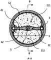
- Figure 13 contains a B material and a steel tube concrete compression member with a shell volume compensation device, cross-sectional view;
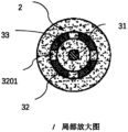
- Figure 14 contains a B material and a steel tube concrete compression member with a shell volume compensation device, a partial enlarged view of the cross section;
- Fig. 15 contains a kind of B material and a shell volume compensator in the steel tube concrete compression member of a shell volume compensator, longitudinal section view,
- Figure 16 contains a B material and a steel tube concrete compression member with a shell volume compensation device, a longitudinal plan view;
- Fig. 17 Contains a B material and six CFST compression members with shell volume compensation devices, longitudinal plan view;
- Fig. 18 Contains a B material and six steel tube concrete compression members with shell volume compensation devices, cross-sectional view;
- Fig. 19 Contains two B materials and a steel tube concrete compression member with a shell volume compensation device, longitudinal plan view;
- Figure 20 is a cross-sectional view of a CFST compression member containing two B materials and a shell volume compensation device
- Fig. 21 Contains two B materials and a CFST compression member with a shell volume compensation device, a partially enlarged view of the cross section;
- Fig. 22 Contains two B materials and two steel tube concrete compression members with shell volume compensation devices, longitudinal plan view;
- Figure 23 is a cross-sectional view of a CFST compression member containing two B materials and two shell volume compensation devices
- Fig. 24 Contains two B materials and two CFST compression members with shell volume compensation devices, partial enlarged view of the cross section;
- Fig. 25 Contains two B materials and four steel tube concrete compression members with shell volume compensation devices, longitudinal plan view;
- Fig. 26 is a cross-sectional view of a CFST compression member containing two B materials and four shell volume compensation devices;
- Fig. 27 Contains two B materials and four CFST compression members with shell volume compensation devices, partial enlarged view of the cross section:
- Fig. 28 Contains two B materials and a steel tube concrete arch compression member with a shell volume compensation device, longitudinal plan view;
- Figure 29 contains two B materials and a steel tube concrete arch compression member with a shell volume compensation device, cross-sectional view;
- Fig. 30 Contains two B materials and a CFST arch compression member with a shell volume compensation device, a partial enlarged view of the cross section;
- Figure 31 Contains three B materials and a steel tube concrete compression member with a shell volume compensation device, cross-sectional view;
- Fig. 32 Contains three B materials and a steel tube concrete compression member with a shell volume compensation device, a partially enlarged view of the cross section;
- Fig. 33 is a cross-sectional view of a CFST compression member containing three B materials and two shell volume compensation devices;
- Fig. 34 Containing three kinds of B materials and two CFST compression members with shell volume compensation devices, partial enlarged view of the cross section.
- Fig. 35 Contains three kinds of B materials and four steel tube concrete compression members with shell volume compensation devices, longitudinal cross-sectional view;
- Fig. 36 Contains three B materials and four steel tube concrete compression members with shell volume compensation devices, cross-sectional view;
- Fig. 37 Contains three kinds of B materials and four steel tube concrete compression members with shell volume compensation devices, cross-sectional half-sectional view;
- Figure 38 Steel pipe containing three cavities used as part A, cross-sectional view.
- Figure 39 A lattice column with three columns
- Figure 40 A lattice column with three columns.
- a volume compensation device with a shell including a pressure supply device and a support shell;
- the support shell is surrounded by a cavity, and there is a connecting channel between the cavity and the surrounding space area outside the support shell;
- the pressure supply device is in the cavity
- the pressure supply device can provide pressure to the medium in contact with it.
- Figures 1 to 4 Take Figures 1 to 4 as examples for illustration. These figures are for illustration only and do not constitute a limitation to the content of the invention.
- Figure 1 is regarded as a cross-sectional view of Figures 2 to 4, and Figure 1 is respectively related to Figures 2, 3 and Figure 4 combines three situations.
- the supporting shell is a steel pipe 32 with a hole 3201 on the pipe wall.
- One end of the pipe is a convex shell, and the other end of the pipe is blocked with a threaded plug 3202. 3202 can be removed and installed from the pipe 32.
- a pressure supply device 31 is installed in the cavity of the support shell 32 . During installation, the pressure supply device 31 is packed into the pipe from the end with the plug, and then the plug 3202 is screwed on.
- the support shell includes an upper part 321, a lower part 322 and a connection sleeve 323.
- the upper part 321 and the lower part 322 can be separated, and the two are connected together by a connection sleeve 323.
- the support shell is divided into upper and lower parts It is to be able to pack the pressure supply device 31 into the cavity of the supporting shell.
- the upper part of the supporting shell has a hole 3211, and the lower part has a hole 3221.
- the supporting shell is the same as that in Figure 3, and the pressure supply device is several spherical air bags or/and spherical air-liquid bags or/and solid elastomer spheres.
- the hole 3201 on the pipe wall in Fig. 1 and Fig. 2 is the connecting channel; the hole 3211 and the hole 3221 in Fig. 3 and Fig. 4 are also connecting channels.
- support shells include tubes, convex shells.
- the outer contour of the cross section of the pipe is convex, suitable for bearing the uniform normal pressure around; preferably, the outer contour of the cross section of the pipe is circular or elliptical.
- the supporting shell is a pipe
- the connecting channel connecting the regions, the cross-section of this channel is the same as the cross-section of the tube cavity.
- the convex shell used as a supporting shell is a spherical shell or an ellipsoidal shell with holes.
- the materials for making the pipe and the convex shell are metal, composite material and macromolecule material.
- the pipe and the convex shell are made of structural steel.
- pressurizing devices includes pressurizing devices, energy storage devices and pressurized energy storage devices.
- the energy storage device has the following characteristics,
- the apparent volume of the energy storage device becomes smaller, and the energy storage device absorbs energy; or/and, when the pressure on the outer surface of the energy storage device decreases, the apparent volume of the energy storage device increases, and the energy storage device absorbs energy. A device that releases energy.
- the selection range of the energy storage device includes air bags, gas-liquid bags, energy storage liquid bags, solid elastomer energy storage devices, and elastic shell energy storage devices.
- the feature of the energy storage liquid bag is that the liquid bag is connected with the accumulator through a pipeline, when the liquid pressure in the liquid bag increases, the liquid is squeezed into the accumulator; when the liquid pressure in the liquid bag decreases, The fluid in the accumulator flows out of the accumulator.
- the air bag is characterized in that the air bag is filled with compressed gas.
- the characteristic of the gas-liquid capsule is that the capsule is filled with liquefied gas, and part of the medium in the capsule is in gaseous state, while the other part is in liquid state.
- Said pressurizing device is characterized by the ability to vary or maintain the pressure between its outer surface and the medium in contact with it.
- the selection range of the pressurizing device includes a pressurized air bag, a pressurized liquid bag, a pressurized gas-liquid bag, and a self-expanding device.
- the self-expanding device is a type A self-expanding device; preferably, the type A self-expanding device is a type A self-expanding device; preferably, the type A1 self-expanding device is a type A1a or/ and a Type 1b self-expanding device.
- the self-expanding device is a Type B self-expanding device.
- the pressurized air bag is connected with an air pressure source through a pipeline, and the air pressure source can adjust the gas pressure in the pipeline and the air bag.
- the air pressure source is an air pump.
- the pressurized air bag becomes an energy storage device.
- the pressurized liquid bag is connected with a hydraulic source through a pipeline, and the hydraulic source can adjust the liquid pressure in the pipeline and the liquid bag.
- an accumulator is also connected to the pipeline of the pressurized liquid bladder. If the volume of the accumulator is small, the accumulator only plays a role in stabilizing the pressure, and the pressurized liquid bladder can still be regarded as a pressurized liquid bladder. ; If the volume of the accumulator is larger, the pressurized liquid bladder becomes a pressurized energy storage liquid bladder.
- the pressurized air-liquid bag is connected with the air pressure source or/and the hydraulic pressure source through the pipeline, and the air pressure source or/and the hydraulic pressure source can adjust the gas or/and liquid pressure in the pipeline and the air-liquid bag.
- the pressurized energy storage device has the following characteristics A and B,
- the characteristic A is,
- a pressurized energy storage device capable of changing or maintaining the pressure between its outer surface and the medium in contact with it;
- the characteristic B is,
- the apparent volume of the pressurized energy storage device becomes smaller; or/and, if the pressure of the surrounding flowable medium decreases, the pressurized energy storage device The apparent volume of the device increases.
- the selection range of the pressurized energy storage device includes a pressurized air bag, a pressurized air-liquid bag, a pressurized energy storage liquid bag, a type A self-expanding device and a type B self-expanding device.
- the Type A self-expanding device is a Type A1 self-expanding device; preferably, the Type A1 self-expanding device is a Type A1a or/and a Type A1b self-expanding device.
- the gas in the pressurized air bag and the pressurized air-liquid bag is compressible and has the function of energy storage, so they can be regarded as pressurized energy storage devices.
- the characteristic of the pressurized liquid bag is that the liquid bag is not only connected with the hydraulic pressure source through the pipeline, but also connected with the accumulator.
- the hydraulic source can adjust the liquid pressure in the pipeline; the accumulator stores and releases energy to stabilize the liquid pressure.
- the characteristics of the fluid-solid conversion pressure supply device are: (1) there is a fluid medium inside the pressure supply device, which is the main source of pressure generated by the pressure supply device; (2) the fluid medium increases with time, Convert from fluid to solid.
- the fluid-solid conversion pressure supply device is an energy storage liquid bag, a pressurized liquid bag or a pressurized energy storage liquid bag, and the fluid medium in the bag is a fluid-solid conversion material.
- the bladder device includes a bladder pressurization device, a bladder energy storage device and a bladder pressurization energy storage device.
- the bladder pressurization devices include pressurized air bladders, pressurized liquid bladders, and pressurized gas-liquid bladders;
- Bladder energy storage devices include air bladders, gas-liquid bladders and energy storage liquid bladders
- Bladder pressurized energy storage devices include pressurized air bladders, pressurized air-liquid bladders, and pressurized energy storage liquid bladders.
- the bladder pressure supply device includes common bladders, upper limit bladders, lower limit bladders and double limit bladders.
- the common capsules include common air capsules, common air-liquid capsules, and common liquid capsules;
- the upper-limit capsules include upper-limit air capsules, upper-limit gas-liquid capsules, and upper-limit liquid capsules;
- the lower-limit capsules include lower-limit air capsules, lower-limit gas-liquid capsules, and lower-limit liquid capsules.
- the double-limited sac includes a double-limited air sac, a double-limited air-liquid sac, and a double-limited liquid sac.
- the normal capsule is capable of changing apparent volume by undergoing a shape change and/or a size change.
- the walls of the ordinary bladder are made of materials that are prone to bending deformation and tensile deformation; preferably, the wall material of the ordinary bladder is rubber.
- the walls of the common air bag, common air-liquid bag, and common liquid bag are all made of materials that are prone to bending deformation and tensile deformation; preferably, the common air bag, common air-liquid bag, and The wall material of common fluid bladder is rubber.
- one of the preferred schemes is to inflate the air bag or the air-liquid bag to the designed level only when the ordinary air bag or the ordinary air-liquid bag is in the cavity of the supporting shell.
- pressure value When the air pressure reaches the design value, the outer wall of the air bag or the air-liquid bag is in close contact with the inner wall of the support shell and there is a contact pressure stress, and the air pressure in the air bag or the air-liquid bag is almost equal to that between the outer surface of the air bag or the air-liquid bag and the support shell. Normal stress between inner surfaces.
- a barrier is placed at the hole in the inner wall of the support shell to prevent the capsule wall from being squeezed into the hole.
- the barrier is a sheet-like object; preferably, the barrier is a plastic sheet.
- the upper limit capsule has the following characteristics: if both the inner and outer surfaces of the capsule wall are only in contact with fluid, and the internal pressure is higher than the external pressure; then,
- the apparent volume and external shape of the cap capsule are relatively stable, and no longer change significantly with the increase of the pressure difference.
- the volume of the upper limit capsule is changed by changing the shape; preferably, the capsule wall material is a material that can be bent but has little tensile deformation; preferably, the production method of the capsule wall material is Apply impermeable materials such as curable rubber on the high-strength fiber fabric.
- the upper limit capsule is wrapped with a restriction sleeve outside the ordinary capsule, and the restriction sleeve is made of high-strength fibers.
- the restriction sleeve When the ordinary capsule is inflated to be in close contact with the restriction sleeve, the restriction sleeve will limit the expansion of the capsule wall.
- the bladder wall and the constraint sleeve When the internal fluid pressure is increased, the bladder wall and the constraint sleeve will jointly resist the pressure of the fluid in the bladder, and the expansion of the bladder will be limited.
- the upper-limit capsule is an upper-limit air capsule or an upper-limit gas-liquid capsule; preferably, when the upper-limit capsule reaches the volume upper limit, its shape and size are suitable for being put into the cavity of the support shell.
- an upper limit air bag or an upper limit air-liquid bag is placed in the cavity of the support shell;
- a plurality of upper-limit air bags or upper-limit air-liquid bags whose air pressure meets the requirements are placed in the cavity of the support shell;
- the support shell is a pipe with a circular cross-section, and a circular tubular upper limit air bag or a circular tubular upper limit air-liquid bag is placed inside the pipe as an energy storage device, see Figures 1 to 3.
- the upper limit air bag 31 or the upper limit The length of the air-liquid bag 31 is lower than the length of the supporting shell (Fig. 2), and when the air-liquid bag 31 or the air-liquid bag 31 reaches the upper limit volume, the outer diameter of the cross section is slightly smaller than the inner diameter of the pipe.
- a plurality of circular tube-shaped upper-limit air cells or upper-limit gas-liquid cells are placed inside the tube, and the total length of the gas cells or gas-liquid cells is less than the support shell.
- the support shell is a pipe with a larger diameter, and a plurality of spherical upper-limit gas bags or spherical upper-limit air-liquid bags are placed inside the pipe, as shown in Figure 4.
- at least one of the two ends of the pipe is not sealed. Blocking; Preferably, both ends of the pipe are blocked;
- the diameter of the spherical upper limit air bag or the upper limit gas-liquid bag is slightly smaller than the inner diameter of the support shell; preferably, when the volume upper limit is reached, the diameter of the spherical upper limit air bag or the upper limit gas-liquid bag is the same as
- the ratio of the inner diameter of the pipe is between 0.5 and 07, or between 0.7 and 0.95.
- the support shell is a spherical shell or an ellipsoidal shell, and one or more spherical upper-limit air bags or upper-limit air-liquid bags are placed in the cavity of the shell.
- the lower limit capsule has the following characteristics: when the internal and external pressure difference is negative, the shape or/and apparent volume of the capsule is the shape and volume required by the design.
- the internal and external pressure difference is the difference between the fluid pressure inside the capsule and the fluid pressure outside the capsule.
- a support of a certain shape is placed inside the lower limit capsule, and the shape of the support determines the final shape of the capsule wall under the action of external high pressure.
- the shape of the support includes three-leaf, four-leaf, dumbbell-shaped, round, etc., see Figure 8.
- the support is three-leaf, four-leaf, dumbbell, It is made of circular steel pipe, and there are many small holes distributed on the wall of the steel pipe, through which the gas can pass; preferably, the diameter of the small holes is between 0.1-1mm.
- the tangential elongation of the capsule wall material of the lower limit capsule is very small, and dumbbell-shaped, trilobate, and quatrefoil-shaped supports (see Figure 8) are placed inside, and the section perimeter of the capsule will be slightly greater than or Equal to the perimeter of the cross-section of the support.
- the lower-limited capsule is actually a double-limited capsule.
- the tangential elongation of the capsule wall material is very large (such as rubber), and the support can also be round, Triangle, square and other shapes.
- Fig. 9 and Fig. 10 are the schematic diagrams of putting the trilobate-shaped support into the capsule.
- the static pressure on the outer surface of the surrounding capsule wall presses the capsule wall 312 to the surface of the support 311, the shape of the wall capsule 312 and the support Object 311 is the same (Fig. 9); when the fluid pressure in the capsule is greater than the surrounding static pressure, the lower limit capsule expands; when the capsule wall is fully expanded, the section will be approximately circular, as shown in Fig. 10.
- the pressure supply device is a double-limit air bag.
- the dual-limit airbag has the characteristics of the upper limit airbag and the lower limit airbag at the same time, that is, it has the following two characteristics:
- the pressure difference is the difference between the fluid pressure inside the capsule and the fluid pressure outside the capsule;
- the shape of the bladder is elongated, all or almost all materials of the bladder are of the same type, and there is no obvious section between the parts of the bladder.
- the elongated integrated bladder is Rubber bladder.
- It includes a flexible pipeline and blocking devices at both ends, and the flexible pipeline is connected with the blocking devices at both ends.
- the material of the flexible pipeline can be bent at least in the circumferential direction, and the bending stiffness is close to 0; the elongation strain of the material of the flexible pipeline in the circumferential direction of the pipeline is less than a given value ⁇ ; Preferably, the elongation strain of the material of the flexible pipeline in the circumferential direction of the pipeline is greater than a given value ⁇ ; preferably, the ⁇ is less than or equal to 5%.
- the flexible pipeline is a rubber tube or a flexible PVC tube that can be stretched in the circumferential direction.
- the flexible pipeline is a thin-walled metal tube with a wall thickness close to the thickness of the side wall of a can; preferably, the cross-sectional shape of the bag is trilobal or quatrefoil before the bag is filled with fluid.
- the pressure supply device is a solid elastic body energy storage device.
- the solid elastic body energy storage device is a solid elastic body, and the material of the elastic body is a material with high elastic deformation such as rubber and polyurethane.
- the pressure supply device is an elastic shell energy storage device.
- the characteristic of the elastic shell energy storage device is that the shell is made of elastic material, and the shell surrounds a closed cavity; when subjected to the pressure of the surrounding liquid, at least a part of the shell is deformed.
- This shell mainly stores energy by bending and deforming.
- the self-expanding device is a device whose apparent volume can expand, or a device whose apparent volume can expand under certain conditions.
- Type A self-expanding device includes a skin and a gas generating device.
- the skin is a closed device made of impermeable or almost impermeable material that can change the apparent volume, or a closed device that can change the apparent shape and apparent volume; Impermeable means that gases and/or liquids under pressure are not able to seep through the skin.
- the gas generating device can generate gas, which squeezes the outer skin from the inside, increasing the apparent volume of the self-expanding device.
- the outer skin of the Type A self-expanding device is a closed device made of polymer material, and when it is fully inflated, its shape is tubular, spherical or ellipsoidal; preferably, the polymer material is rubber.
- the outer skin of the Type A self-expanding device is a non-circular cross-section metal thin-wall tube with both ends blocked.
- the shape of the thin-walled tube changes and the apparent volume increases.
- the gas generating device in the Type A self-expanding device contains at least two materials, and the two materials are usually isolated from each other; when a certain condition is met, the two materials mix with each other, a chemical reaction occurs, and gas is generated, and the gas pushes The skin swells.
- the two materials are mixed to generate gas.
- the two materials are sodium bicarbonate and a liquid containing hydrogen ions respectively.
- the self-expanding A safety valve is installed on the device to ensure that the gas pressure is maintained near the preset value. When the gas pressure exceeds the preset pressure value of the safety valve, the gas is discharged from the valve port. When the gas pressure is lower than the preset value, the safety valve is closed .
- the two gas-generating materials are water and polyurethane grouting fluid respectively.
- a type 1a self-expanding device has chemical component a in the closed space surrounded by the outer skin, and a device with chemical component b wrapped in a brittle shell.
- chemical components a and b are mixed, gas can be generated.
- the expansion mechanism is: when the outer skin of the self-expanding device is squeezed, the outer skin will squeeze the brittle outer shell inside, causing it to rupture.
- the chemical components a and b are mixed to generate gas, which pushes the skin to expand.
- the brittle shell is a tube 313 made of brittle material, closed at both ends, and non-circular in section. Further, the section of the glass tube is oval, or rectangular, or a combination of a rectangle and two semicircles, see Figure 5.
- the brittle material is a brittle polymer material or glass; preferably , the brittle polymer material is brittle plastic.
- the outer skin of the self-expanding device is a rubber tube 310 with both ends closed, as shown in Fig. 6, inside which is placed chemical composition a (312) and a glass tube 313 with both ends closed and a rectangular section, and the liquid filled in the glass tube is Chemical composition b (314).
- the rubber tube squeezes the Radix Radix 313 inside, causing it to rupture, and then the liquid chemical component a (314) flows out and reacts with component b (312) to generate gas.
- component a is sodium carbonate
- component b is hydrochloric acid.
- component a is polyurethane grout
- component b is water
- the two are mixed and foamed, resulting in volume expansion, and the resultant has a certain strength after curing.
- the masses of the chemical components a and b are determined according to the mass of the production gas, which is determined according to the ambient temperature, the volume of the gas and the pressure of the gas.
- a safety valve is provided on the self-expanding device, and when the gas pressure exceeds a preset value, part of the gas is discharged to ensure that the pressure does not exceed a specified value.
- a type 1b self-expanding device a brittle shell capsule
- a and B placed in the confined space of the A1b type self-expanding device.
- the shells of the devices A and B are both brittle shells.
- a chemical component a is placed inside the device A, and another chemical component is placed inside the device B.
- a chemical component b that can generate gas when components a and b are mixed.
- the self-expanding device is a PVC pipe 310 with both ends closed, as shown in Figure 7.
- the brittle plastic pipe 311 is filled with chemical
- the liquid 312 with composition a the brittle plastic tube 313 is filled with liquid 3214 with chemical composition b.
- the brittle plastic tubes 3211 and 3213 will rupture successively or simultaneously.
- the liquids 314 and 312 in the two brittle plastic tubes flow out, a reaction reaction occurs after mixing, and the gas generated expands outward from the rubber tube squeezed from the inside.
- component a is sodium carbonate solution and component b is hydrochloric acid.
- component a is polyurethane grouting fluid
- component b is water
- the two are mixed and foamed to produce volume expansion, and the resultant has a certain strength after curing.
- the B-type self-expanding device is made of shape memory alloy, or the material used includes shape memory alloy.
- the shape of the memory alloy changes, and then the volume of the self-expanding device changes.
- the volume enclosed by the outer surface of the self-expanding device is the minimum or close to the minimum; when the temperature is in the T2 range, the external volume of the device is the largest or close to the maximum; the internal temperature of the composite structure is not in T1 Within the interval temperature range, but within the T2 interval temperature range;
- the memory alloy self-expanding device Before being used to apply pressure to the material of part B in the cavity surrounded by part A, the memory alloy self-expanding device is placed in the temperature range of T1; after being placed in the cavity surrounded by part A, since the temperature is in the temperature range of T2, The external volume of the device expands and squeezes the material of part B.
- a commonly used self-expanding device is a tube made of shape memory alloy and closed at both ends.
- T2 the temperature enters the range of T2
- the cross-sectional shape of the pipe wall changes, and the surrounding volume on the outer surface expands, which exerts pressure on the cement-containing material;
- the cross-sectional shape of the pipe wall changes, at least one section of the pipe wall on the cross-section will Bending; due to the ability of the pipe wall to store a large amount of elastic energy when it bends, this device also has an energy storage function.
- Another self-expanding device is made of flexible material and memory alloy. When the shape of the memory alloy changes, the flexible material changes together, thereby changing the volume surrounded by the outer surface of the self-expanding device.
- a method for manufacturing a volume compensating device with a shell which is characterized in that the volume compensating device with a shell can be manufactured by this method.
- a method for making a volume compensation device with a shell comprising making a supporting shell and making a pressure supply device for the device.
- the pressure supply device is installed in the cavity of the support shell.
- a method for providing pressure to the surrounding medium using a volume compensation device with a shell characterized in that,
- the fluid-solid conversion material is present between the inner wall of the support shell and the outer surface of the pressure supply device; or/and,
- the fluid-solid transfer material exists in at least a part of the surrounding space outside the support shell;
- the device When the fluid-solid conversion material is in a flowable state, the device has the following characteristic A or/and characteristic B,
- the property A is,
- the fluid-solid conversion material flows into the cavity surrounded by the support shell through the channel, squeezing the pressure supply device in the cavity , making the apparent volume of the pressure supply device smaller; or/and,
- the characteristic B is,
- the fluid-solid conversion material and the supporting shell form a composite shell, and the composite shell resists the pressure of the external medium as a whole.
- the support shell 32 has a hole 321
- the pressure supply device 31 is located in the cavity surrounded by the support shell 32, and there is a fluid-solid conversion material 331 between the outer surface of the pressure supply device and the inner wall of the support shell.
- a fluid-solid conversion material 333 exists in the outer peripheral space of the support shell 32.
- the fluid-solid conversion materials 331, 332 and 333 in the different regions are the same material.
- the fluid-solid conversion material surrounds the entire outer surface of the support shell 32; preferably, only a part of the outer surface of the support shell is in contact with the fluid-solid conversion material.
- a composite structure comprising parts A, B and C; wherein
- Part A is surrounded by a cavity and is made of solid material
- Part B consists of a fluid-solid transition material, which is a material capable of changing from a flowable state to a solid state;
- Part C is one or more volume compensating devices with a shell, each volume compensating device with a shell includes a support shell and a pressure supply device, and the pressure supply device is in the cavity of the support shell;
- the volume compensating device with shell and the material of part B are located in the cavity surrounded by part A.
- the fluid-solid conversion material in the gap between the outer surface of the pressure supply device and the inner surface of the support shell or/and in the outer peripheral area of the support shell; preferably, the fluid-solid conversion material and the part B material are The same material, or the same material as a Part B material.
- the A part is surrounded by a cavity.
- the part A is surrounded by two or more cavities, and the cavities have the following characteristics:
- At least two cavities are in communication with each other; the communication means that there is a connecting channel between the two cavities, and the medium in a flowable state can flow from one cavity to the other; or/and,
- At least two cavities are isolated from each other; the isolation means that there is no connecting channel between the two cavities.
- the part A includes a pipe and the blocking device at both ends thereof.
- the cross section of the blocking device at at least one end is larger than the cross section of the pipe; preferably, the cross section of the blocking device at at least one end is The enclosing figure of the outer contour line of the section is the same as the enclosing figure of the outer contour line of the cross section of the pipe.
- the pipe is a steel pipe or an FRP pipe.
- the A part is a spherical or ellipsoidal shell.
- the cavity 2.2 in the three-cavity steel pipe is adjacent to the cavity 2.1 and the cavity 2.3 respectively, wherein the cavity 2.1 and 2.2 are connected, and there are holes on the partition 12.2 between the two 12.2.1; the cavities 22. and 2.3 are isolated.
- the cavities of the column limb 12.1, column limb 12.2 and column limb 12.3 in the three-limb lattice column are isolated from each other, Each cavity is filled with concrete.
- the pipe is not connected to the column limb.
- the material in part B is a fluid-solid conversion material, and the selection range of the fluid-solid conversion material includes but is not limited to the following:
- the cement-based materials include cement mortar, reactive powder concrete (RPC), normal-strength concrete (NHSC), high-strength concrete (HSC), and ultra-high-strength concrete (UHSC);
- the polymer material is a polymer emulsion
- the polymer material is a polymer material capable of curing itself, including epoxy resin;
- the self-curable polymer material includes epoxy resin
- the part B material is a mixture of polymer material and solid powder; preferably, the part B material is a mixture of polymer material and solid particles; preferably, the part B material is a polymer material, solid Mixtures of powders and solid particles;
- the solid powder is metal powder or inorganic non-metallic material powder; the solid particles are metal particles or inorganic non-metallic material particles; preferably, the inorganic non-metallic material powder and particles are respectively stone powder and pebbles.
- each B-part material is a fluid-solid transition material.
- said Part B material has at least one of the following characteristics A and B:
- the B j material has relatively high fluidity
- the end moment of the flowable state of the B j material is later than or equal to the end moment of the flowable state of the B i material, and earlier than the volume shrinkage turning point of the B i material; or,
- the end time of the flowable state of the B j material is later than or equal to the time when the volume shrinkage turning point of the B i material occurs.
- At least one cavity surrounded by part A there is at least one i, 1 ⁇ i ⁇ M, and the corresponding B i material has one or two or three of the following characteristics A, B and C ,
- the B i material When the B i material is in the flowable state stage, in one of the time periods, or multiple time periods, or all stages, at least the B i material is subjected to compressive stress among all the B part materials;
- the B i material After the B i material is solidified, at least the B i material is subjected to compressive stress or precompressive stress or residual precompressive stress among all the B part materials.
- At least in one cavity surrounded by said part A there is also a simplified pressurization device capable of changing and/or maintaining the compressive stress of the B material in the cavity surrounded by part A.
- the selection range of the simplified pressurization device includes a pressurization piston, a pressurization pipeline and the medium therein, and a retarding pressurized liquid bladder.
- the pressurizing piston is a rod of solid material with a smooth surface. It passes through the piston hole on part A and extends into the cavity surrounded by part A. The pressurizing piston and the piston hole are sealed; the pressurizing piston can Move along its length to increase its pressure by displacing the space occupied by the Part B material, or/and decrease the pressure by giving way to the space it occupies.
- the pressurized pipeline and the medium therein are pipelines connected to the external pressure source and the cavity surrounded by part A, and the medium in the pipeline is the material of part B in a flowable state; when the pressure source increases the pressure , the material of part B in the pipeline enters the cavity surrounded by part A;
- the characteristic of the retarding pressurized liquid bag is that the liquid bag is located in the cavity surrounded by part A; the liquid bag is filled with a slow-setting fluid-solid conversion material, and the moment of solidification is later than the moment of the end of pressurization.
- the member has an axis over one, or more or all of its lengths of the combined structure
- the axis has at least one of the following characteristics
- the figure surrounded by the outer contour of the cross section of the component is a figure surrounded by straight lines or/and curves; preferably, the figure is Convex; preferably, the figure is a convex polygon; preferably, the figure is a convex curve figure; preferably, the figure is a circle or an ellipse; preferably, the figure is a rounded polygon .
- At least one of the cavities surrounded by the outer contour of the cross section is a straight line or/and A figure enclosed by a curve; preferably, the figure is convex; preferably, the figure is a convex polygon; preferably, the figure is a convex curve figure; preferably, the figure is a circle or An ellipse; preferably, the figure is a polygon with rounded corners.
- the shape and size of the cross-section are respectively the same at different positions in the length direction;
- the cross-sections at different positions in the length direction are similar in shape but different in size;
- the composite structural member is a cylindrical compression member with a linear axis and only one cavity; preferably, the composite structural member is a compression member with an arched curve axis and only one cavity; the The shape and size of the cross-section of the arched compression member do not change along the length direction.
- At least one cavity surrounded by part A there is at least one i and one j, where 1 ⁇ i ⁇ M, 1 ⁇ j ⁇ M, i ⁇ j, and the corresponding B i material is adjacent to B j material; two The relationship between them has one of the following properties,
- the isolation device is a thin iron cylinder
- the B i material is on the inside of the cylinder
- the B j material is on the outside of the cylinder; preferably, the upper and lower ends of the cylinder are sealed.
- the upper end is left with a feed port, and any boundary surface of the B i material is not in direct contact with the B j material; preferably, the upper end of the cylinder is not blocked, and the upper end of the B i material is directly connected to the upper end of the B j material. touch.
- a method for making a combined structure comprising obtaining part A, putting one or more volume compensating devices with a shell into the cavity surrounded by the part A, filling the cavity with material of part B, and filling the cavity with The part B material applies pressure.
- the material of the part B is a fluid-solid conversion material, and when filling the cavity surrounded by the part A, at least a part of the material of the part B is in a flowable state;
- the shelled volume compensation device includes a pressure supply device and a support shell. When appropriate, fill the gap between the outer surface of the pressure supply device and the inner surface of the support shell with a fluid-solid conversion material.
- the fluid-solid conversion material in a flowable state is filled at least between the outer surface of the pressure supply device and the inner surface of the support shell in the void; or/and,
- the part B material in the peripheral area near the outer surface of the support shell passes through the support shell into the gap between the outer surface of the pressure supply device and the inner surface of the support shell.
- the A part is surrounded by a cavity.
- the part A is surrounded by two or more cavities, and the cavities have the following characteristics:
- At least two cavities are in communication with each other; the communication means that there is a connecting channel between the two cavities, and the medium in a flowable state can flow from one cavity to the other; or/and,
- At least two cavities are isolated from each other; the isolation means that there is no connecting channel between the two cavities.
- the types of the materials of the B part include the following four categories:
- the cement-based materials include cement mortar, reactive powder concrete (RPC), normal-strength concrete (NHSC), high-strength concrete (HSC), and ultra-high-strength concrete (UHSC);
- the polymer material is a polymer emulsion
- the polymer material is a polymer material capable of curing itself, including epoxy resin;
- the self-curable polymer material includes epoxy resin
- the part B material is a mixture of polymer material and solid powder; preferably, the part B material is a mixture of polymer material and solid particles; preferably, the part B material is a polymer material, solid Mixtures of powders and solid particles;
- the solid powder is metal powder or inorganic non-metal material powder; the solid particles are metal particles or inorganic non-metal material particles; preferably, the inorganic non-metal material powder and particles are stone powder and pebbles, respectively.
- part B At least in one cavity surrounded by part A, there are M kinds of materials of part B, respectively B 1 , B 2 ... B i , B i+1 ... B M materials, which respectively occupy different spatial regions.
- said Part B material has at least one of the following characteristics A and B:
- the B j material has relatively high fluidity
- the end moment of the flowable state of the B j material is later than or equal to the end moment of the flowable state of the B i material, and earlier than the volume shrinkage turning point of the B i material; or,
- the end time of the flowable state of the B j material is later than or equal to the time when the volume shrinkage turning point of the B i material occurs.
- At least one cavity surrounded by part A there is at least one i, 1 ⁇ i ⁇ M, and the corresponding B i material has one or two or three of the following characteristics A, B and C ,
- the B i material When the B i material is in the flowable state stage, in one of the time periods, or multiple time periods, or all stages, at least the B i material is subjected to compressive stress among all the B part materials;
- the B i material After the B i material is solidified, at least the B i material is subjected to compressive stress or precompressive stress or residual precompressive stress among all the B part materials.
- B M In the cavity surrounded by the part A, there is a B M material inside the support shell or/and in the surrounding area outside the support shell of the volume compensation device with a shell; when 1 ⁇ i ⁇ M-1, B M The end time of the flowable state of the material is later than or equal to the end time of the flowable state of any Bi material.
- the B material in the cavity surrounded by the A portion has the following properties:
- the pressure supply device in the shell volume compensation device expands, pushing the B M material in the support shell to flow out through the hole, filling the volume change in the cavity surrounded by part A due to the contraction of the B i material.
- spacers are provided between the different Part B materials.
- the isolating device is made of impermeable material to prevent mixing of components of different B-part materials.
- the material of the isolating device and the B-part material have better bonding properties, In order to prevent the shear capacity of the material of part B and the isolation device from being too low at the interface, which will affect the bearing capacity of the component.
- the material for the isolation device is selected as a metal sheet.
- the spacer has satisfactory permeability so that different Part B materials can penetrate into the material of the spacer, maintaining a good bond with the spacer.
- the material of the spacer is mesh Shape material;
- the mesh material is a metal mesh.
- the metal mesh is installed on a fixing frame, and the fixing frame is installed in the cavity surrounded by the A part.
- the spacer is deformable so that the volume of the area it encloses changes.
- there is only one shelled volume compensating device in the cavity enclosed by part A see FIGS. 12 to 14 .
- the position of the volume compensation device with a shell is axisymmetric about a certain straight line.
- said part B material is cement mortar, preferably said part B material is reactive powder concrete.
- the pressure supply device in the volume compensation device with the shell pushes the B2 material in contact with it to flow out of the hole in the supporting shell to fill up the B1 Volume change due to material shrinkage.
- the B1 and B2 materials have one of the following two characteristics: (1) The end time of the flowable state of the B2 material is later than or equal to the end time of the flowable state of the B1 material and earlier than the B1 material The moment when the turning point of volume shrinkage appears; (2) The end moment of the flowable state of the material B2 is later than or equal to the moment when the turning point of volume shrinkage of the material B1 appears.
- the B2 material is retarded mortar or active powder concrete or retarded epoxy resin; preferably, the B1 material is concrete; preferably, the B1 material is B2 material and coarse aggregate mixture.
- the pressure supply device in the shell volume compensation device pushes the B3 material in contact with it from the hole of the supporting shell flow out, filling the shrinkage volume of B1 or/and B2 material.
- the B 1 , B 2 and B 3 materials have one of the following three characteristics:
- the end moment of the flowable state of the B2 part material is later than the moment when the volume shrinkage turning point of the B1 material occurs; or/and,
- the end time of the flowable state of the B3 material is later than the end time of the flowable state of the B2 material, and earlier than the volume shrinkage turning point of the B2 material;
- the end moment of the flowable state of the B2 part material is later than the moment when the volume shrinkage turning point of the B1 material occurs; or/and,
- the end time of the flowable state of the B3 part material is later than the time when the volume shrinkage turning point of the B2 material occurs;
- the end time of the flowable state of the B2 part material is later than or equal to the end time of the flowable state of the B1 material, and earlier than the volume shrinkage turning point of the B1 material; or/and,
- the end time of the flowable state of the B3 material is later than or equal to the end time of the flowable state of the B2 material, and earlier than the volume shrinkage turning point of the B2 material.
- the end time of the flowable state of the B2 part material is later than the moment when the volume shrinkage turning point of the B1 material occurs; or/and, the end time of the flowable state of the B3 part material is later than the volume shrinkage of the B2 material The moment of turning point.
- the ultimate bearing capacity of the supporting shell should meet the following requirements: when the combined structure is in the limit state of bearing capacity, it is required that the supporting shell withstand the maximum compressive stress of the surrounding medium not less than the surrounding medium acting on the support pressure on the shell wall.
- the concrete-filled steel tube axial compression member is taken as an example for illustration. Assume that part A of the combined structure is a steel pipe with a circular cross-section, and the supporting shell is a circular steel pipe with holes in the pipe wall. When the composite structure is destroyed due to axial compression, the entire structure undergoes axial compression and radial expansion. The material B in the cavity surrounded by part A bulges radially, which is the main factor causing the entire structure to bulge outward. Part A enters yield due to axial compression and tangential tension. In this failure mode, the Avoid the solidified fluid-solid transition material around the support shell becoming a weak area due to insufficient radial bearing capacity or insufficient radial stiffness.
- the equivalent maximum radial compressive stress on the outer surface of the steel pipe of the support shell is the combined Radial compressive stress of material B when the structure fails. It is approximately considered that the maximum radial compressive stress of the B material is the radial compressive stress on the inner surface of the A part when the A part yields or when the combined structure reaches the limit of the bearing capacity.
- the radial bearing capacity of the supporting shell is determined by an equivalent method.
- the steel pipe of the support shell is equivalent to a steel pipe without holes in the wall.
- the equivalent method is to take a length of the steel pipe with holes in the wall, calculate its radial bearing capacity, and then The radial bearing capacity at different positions in the length direction is averaged.
- the length, outer diameter and average radial bearing capacity of the equivalent pipe wall without holes are the same as those of the steel pipe with holes in the pipe wall.
- Another equivalent method is to combine the solidified fluid-solid conversion material within a certain radius around the support shell and the support shell with holes in the pipe wall to form a new structure called a composite shell. Calculation Radial bearing capacity of the composite shell. Preferably, when determining the scope of the composite shell, the fluid-solid conversion material in the steel pipe cavity is also taken into consideration.
- the maximum compressive stress and the maximum radial stiffness that the composite shell can bear are much greater than the maximum pressure that the outer surface of the pressure supply device in the cavity of the support shell can withstand and the maximum stiffness of the pressure supply device.
- the stiffness is Refers to: the radial pressure increment acting on the outer surface of the device, divided by the radial displacement caused by the pressure increment, and then divided by the outer diameter of the device.
- the composite shell composed of the fluid-solid conversion material and the supporting shell can withstand the maximum pressure exerted by the surrounding medium, which is much higher than when the pressure supply device works alone The pressure provided by the pressure supply device to the surrounding medium.
- the apparent bulk modulus and apparent bulk deformation modulus of the pressure supply device are respectively much lower than the bulk modulus and bulk deformation modulus of the material of part B at any stage, and the said any stage refers to the whole process
- the whole process means the process of changing the material from a flowable state to a solid state reaching its ultimate strength
- the simplified pressurizing device is installed before or after filling the material of part B into the surrounding cavity of A.
- the simplified pressurizing device is a retarding pressurized liquid bag
- the liquid bag should be installed in the cavity before filling part B into the cavity surrounded by A.
- the simplified pressurizing device is a pressurizing piston, or a pressurizing pipeline and the medium in it, install the pressurizing piston or pressurizing pipeline after completing the filling of part B materials and installing the blocking plate.
- the pressurization includes applying a variable pressure to the medium, or/and maintaining a constant or substantially constant pressure on the medium.
- the pressure supply device is a pressurization device or a pressurized energy storage device.
- B In the gap between the support shell and the pressure supply device In, and around the retaining device of the shelled volume compensation device are B i materials.
- the strength preset value refers to that when the strength of the Bi material is lower than the preset value, if the pressure of the pressure supply device is changed, the change of the pressure of the pressure supply device will cause the near hole on the support shell The stress field of the B i material changes, and this change will cause the damage of the B i material near the hole of the supporting shell or reduce the long-term strength.
- the strength design value means that when the strength reaches the design value, the composite shell formed by the Bi material and the support shell has sufficient load-bearing capacity to resist the pressure of the surrounding medium; when the pressurization device or pressurized energy storage is removed After the pressure applied by the device, the change of the stress field will not reduce the long-term strength of the Bi material near the hole of the support shell, nor will it damage the Bi material there.
- the pressure supply device is a pressurized device or a pressurized energy storage device
- the pressure supply device is an energy storage device or a pressurized energy storage device.
- the Bi material is filled in the gap between the inner wall of the support shell of the device A and the pressure supply device, and in the area around the device A.
- the B j material is filled in the gap between the inner wall of the supporting shell of the device B and the pressure supply device, and in the area around the device B.
- the pressure method is as follows.
- said shelled volume compensating Devices A and B are also in this region.
- the compressive stress applied by the pressurizing device or the pressurized energy storage device in the device A to the Bi material is constant, or fluctuates within a preset range;
- the compressive stress applied by the pressurizing device or the pressurized energy storage device in the holding device A to the B i material is constant, or fluctuates within a preset range; preferably, the pressurized energy storage device in the holding device B is on B j
- the compressive stress applied to the material is constant, or fluctuates within a preset range.
- the pressure applied to the Bi material by the pressure supply device in the shell volume compensation device A is not restricted or the pressure is relieved;
- the compressive stress applied to the B i material by the pressure supply device in device B is not restricted or the pressure is relieved.
- the selection range of the pressurizing device includes a pressurizing piston, a pressurizing pipeline and the medium therein, and a retarding pressurized liquid bladder.
- the pressure supply device is an energy storage device or a pressurized energy storage device.
- B i material the area around the shell is filled with B j material.
- the pressure method is as follows.
- the pressure supply device in the volume compensation device with a shell is selected as a pressurized energy storage device, then use the pressurized energy storage device to pressurize the B i material, or/and use a simplified pressurization device to pressurize the B j material Pressurize.
- said shelled volume compensating The device and said simplified pressurization device are also located in this area.
- the pressure supply device in the volume compensation device with shell is selected as the energy storage device, the pressure applied by the simplified pressurization device to the B j material is kept constant, or the simplified pressurization device is kept surrounded by the A part
- the volume occupied in the cavity is substantially constant;
- the pressure supply device in the volume compensation device with shell is selected as a pressurized energy storage device, then keep the pressure exerted by the pressurized energy storage device on the Bi material constant, or fluctuate within a preset range ; and keep the pressure exerted by the simplified pressurizing device on the B j material constant, or keep the volume occupied by the simplified pressurizing device in the cavity surrounded by the A part substantially constant.
- the pressure applied to the Bi material by the pressure supply device in the volume compensation device with the shell is not restricted or the pressure is relieved;
- the compressive stress applied to the B j material by the simplified pressurizing device is not restricted or the pressure is released.
- the steel tube concrete composite structure is an axial compression member, as shown in Figure 12-14.
- Part A includes an upper block plate 110, a flange 111, a steel pipe 12 and a lower block plate 13.
- the flange 111 is welded on the upper end of the steel pipe 12, and the lower block plate is welded on the lower end of the steel pipe 12.
- Bolts are used to connect the upper block plate and the flange, and the bolt holes 1101 on the upper block plate face the bolt holes 1111 on the lower block plate. Construction holes 1102 and exhaust holes are processed on the upper block plate. hole 1103.
- a volume compensation device with a shell In the cavity of the steel pipe, a volume compensation device with a shell is installed at the axial position; the rest of the cavity is filled with reactive powder concrete (RPC for short).
- the volume compensation device with shell is a circular tube-shaped air bag placed inside a steel pipe with holes.
- the structural form is shown in Figure 1 and Figure 3.
- the end face of the upper part of the supporting shell is in close contact with the end face of the lower part, so that the supporting shell can be moved in the axial direction.
- the withstand pressure reaches the maximum value.
- the airbag is an ordinary airbag.
- a plastic sheet is pasted on the tube wall inside the support shell, so that the plastic sheet covers the circular hole on the tube wall.
- the support shell and the connecting sleeve are connected in a threaded manner; preferably, the support shell and the The connecting sleeves are connected by glue. Inflate the airbag, and the inflation will end when the air pressure reaches 8MPa.
- the pressurizing device can choose a grouting pump, a concrete pump or other pressurizing devices.
- One of the methods is to saw off the construction pipeline from the root.
- the volume of RPC shrinks before and after solidification. If the one-time pressurization method is used without using the shell volume compensation device, when the volume of RPC shrinks, it will The pressure that causes the RPC to decrease or even disappear. If the intermittent pressurization method is used without using the shell volume compensation device, the pressure caused by the volume contraction when the B material is in a flowable state can be eliminated reduce, but cannot eliminate the pressure drop caused by the volume contraction of material B after solidification, because the material B in the long and thin pipeline can basically no longer flow after solidification.
- the one-time compression scheme is applicable if the cross-section is small or/and the volume shrinkage of the B material is low. Under this condition, using a volume compensation device with a shell to maintain the pressure can ensure that the retained precompressive stress reaches the preset value after material B reaches its final strength.
- the technical effect of this scheme is that when the applicable conditions are met, the construction method is simple and the devices used are simple.
- the applicable condition of the intermittent pressurization scheme is that the volume shrinkage rate of material B is high before solidification, and the volume shrinkage rate is very low after solidification.
- the pressure supply device in the volume compensation device with shell is an energy storage device, and the energy storage device is an air bag.
- the scheme of embodiment 1 is suitable.
- the technical effect of this case is that the construction is simple, the construction time is short, and the number of equipment occupied is small. At the same time, it can ensure that the B material in the cavity has compressive stress during the solidification process and after the solidification is completed, and of course it can also prevent the separation of the B material from the inner wall of the A part due to shrinkage.
- part A includes the upper block plate 110, the flange plate 111, the steel pipe 12 and the lower block plate 13 .
- the flange 111 is welded on the upper end of the steel pipe 12
- the lower blocking plate 13 is welded on the lower end of the steel pipe 12 .
- Bolts are used between the upper block plate and the flange, and the bolt holes 1101 on the upper block plate are opposite to the bolt holes 1111 on the lower block plate.
- the upper block plate is processed with a feed hole 1102 and a center hole 1103.
- the volume compensation device with a shell is shown in Figure 15.
- a pressure supply device 31 is placed in a perforated steel pipe 32, and the pressure supply device is a bladder pressurized energy storage device.
- the bladder pressurization device is selected as A pressurized air bag, the air bag is connected to the air pressure source through the pipeline 3101.
- the pressurized energy storage device is a pressurized energy storage liquid bag, and the liquid bag is connected to the hydraulic pressure source and the energy storage through the pressurized pipeline 3101 device connection.
- a screw plug 3202 is installed on the upper end of the steel pipe with holes, and a circular hole 3203 is processed on the screw plug.
- the pressurized pipeline 3101 passes through the circular hole 3203, leaving a gap between the wall of the circular hole and the pressurized pipeline.
- the gap is used to allow gas to escape.
- the pressure supply device used in the volume compensation device with a shell is a lower limit air bag or a lower limit liquid bag, and the shape of the support therein is trilobal, see Figures 8 to 10.
- the plugging method is to use a plug with a hole.
- the diameter of the round hole of the plug is slightly larger than the outer diameter of the inflatable tube, and a groove for placing a sealing ring is processed in the hole of the plug. Before installing the plug, put the sealing ring into the groove, and then install the plug.
- the first is to use an air pump to squeeze compressed air into the pressurized pipeline, and keep the pressure constant when the pressure reaches the preset value, or keep the pressure fluctuating within the required range.
- the preset pressure is relatively low, for example, when the preset pressure is 5-10 MPa, it is more appropriate to use gas for pressurization.
- the second is to use a hydraulic pump to squeeze liquid into the pressurized pipeline, and when the pressure reaches a preset value, the pressure is kept constant, or the pressure fluctuates within the required range.
- an accumulator is installed on the hydraulic pipeline .
- the preset pressure is high, for example, when the preset pressure is 20MPa, 30MPa, 40MPa or 70MPa, it is more reasonable to use liquid pressurization.
- the booster pump and the pressurized pipeline are removed.
- the preset value of the strength is that the compressive strength of the cube is 30-60MPa.
- the CFST composite structure is an axial compression member, as shown in Figure 17 and Figure 18.
- Part A includes an upper block plate 110, a flange 111, a steel pipe 12 and a lower block plate 13.
- the flange 111 is welded on the upper end of the steel pipe 12, and the lower block plate is welded on the lower end of the steel pipe 12.
- Bolts are used to connect the upper block plate and the flange, and the bolt holes 1101 on the upper block plate face the bolt holes 1111 on the lower block plate.
- Construction holes 1102 and exhaust holes are processed on the upper block plate. Hole 1103.
- the diameter of the steel pipe in this example is larger.
- volume compensating devices In the cavity of the steel pipe, six volume compensating devices with shells are installed; the rest of the cavity is filled with reactive powder concrete (RPC for short).
- RPC reactive powder concrete
- the structure of the volume compensation device with a shell is to place a circular tube-shaped gas-liquid bag inside the steel pipe with holes, and the structural form is shown in Fig. 1 and Fig. 2 .
- Construction method is similar to embodiment 1.
- volume compensating devices with shells Due to the large number of volume compensating devices with shells and they are distributed in many places, when the material of part B in the cavity surrounded by part A shrinks, the volume compensating devices with shells can relatively evenly compensate the volume shrinkage in each area, so that B The stress distribution of the material fluctuates less in space.
- the steel tube concrete composite structure is an axial compression member, as shown in Figure 19-21.
- Part A includes an upper block plate 110, a flange plate 111, a steel pipe 12, and a lower block plate 13.
- the upper block plate and the flange plate are connected by bolts, and the bolt holes 1101 on the upper block plate face the lower plate.
- Construction holes 1102 and 1103 are processed on the upper blocking plate.
- Two C-shaped spacers 41 and 42 are placed in the cavity of the steel pipe 12 , their height is slightly lower than the cavity height of the steel pipe 12 , and they divide the cavity into three regions, namely regions 211 , 212 and 22 .
- the same UHSC is filled in regions 211 and 212, and the retarded RPC is filled in region 22.
- the flowable state of RPC ends later than the turning point of volume shrinkage of UHSC.
- the volume compensation device with shell is placed 3 At the axial position of the steel pipe 12, it is in the area 22, surrounded by RPC.
- the length of the shell volume compensation device is slightly smaller than the cavity height of the steel pipe 12.
- the cross-section of the structure of the volume compensation device with a shell is shown in Figure 21, and its longitudinal structure can refer to Figure 2.
- the supporting shell is a steel pipe with holes 32, and there are two rows of holes 321 on the steel pipe, which are arranged symmetrically about the center of the circle.
- the pressure supply device 31 is Upper-limit air bag or upper-limit air-liquid bag. In the cavity area 321 of the steel pipe 32, the hole area 322 and the area 323 around the steel pipe 32 are filled with the same retarded RPC.
- the construction method is as follows.
- the shell volume compensator 31 on the axis position of the steel pipe 12, and install two C-shaped isolating devices 41 and 42.
- the "C" of the isolating device is manufactured.
- the distance between the two ends of the word should be greater than the distance after installation.
- apply pre-pressure to the isolation device Place several support blocks between two C-type isolation devices to apply pre-pressure.
- the two ends of the "C" of the C-shaped isolation device are pasted on the inner wall of the steel pipe 12 with tapes, and the tapes are not folded after pasting.
- two woven bags are placed in the areas 211 and 212 to fill the UHSC, and the perimeter of the woven bags should be greater than or equal to the perimeter of the area 211 or 212 where they are located.
- the UHSC can be prevented from being squeezed between the C-shaped isolation device and the inner wall of the steel pipe 12 .
- the pressurization method can be one-time pressurization and There are two ways of intermittent pressurization. When using intermittent pressurization, the pressurization should be ended before the flowable state of retarded RPC ends, the valve on the pressurization pipeline should be closed, and the pressurization device should be removed.
- the solution in this embodiment is suitable for combined structures with large or super-large sections.
- a setting retarding and antifriction layer is laid at the boundary between the area 211 and the steel pipe 12 and at the boundary between the area 212 and the steel pipe 12 .
- This treatment can avoid the tangential shear stress of the UHSC near the inner wall of the steel pipe due to volume shrinkage in the composite structure of large or super large sections, so that the UHSC in the two regions is in the transverse direction and the compressive stress in all directions is approximately equal This stress state is the most beneficial to improve the axial bearing capacity of UHSC.
- the upper limit air bag is replaced with a pressurized air bag with a pressurized pipeline or a pressurized energy storage liquid bag.
- the construction holes 1102 and 1103 are sealed Treatment.
- the cross section of the combined structure is large , the superiority of this scheme is more obvious.
- the advantage of this technical solution is that it can adapt to the combined structure of large or super large cross-section.
- the retarded RPC at the boundary of the isolation device can push the isolation device into the regions 211 and 212
- the retarded RPC can also be squeezed into the gap, so that the stress state of the UHSC is or close to the hydrostatic pressure state.
- This stress state is conducive to improving the ultimate strength of UHSC; after reaching or approaching the final strength, UHSC in this stress state is conducive to improving the axial compressive bearing capacity of the composite structure.
- Part A includes the upper sealing plate 110, the flange plate 111, the steel pipe 12 and the lower sealing plate 13.
- the upper sealing plate and the lower sealing plate The flanges are connected by bolts.
- a feeding hole 1102 and a piston hole 1103 are processed on the upper blocking plate.
- the spacer 41 and 42 are used to divide the cavity into regions 211, 212 and region 22.
- a volume compensating device with a shell is installed at both lateral ends of the region 22, and is installed at the center of the upper blocking plate.
- pressurizing piston 5 There is pressurizing piston 5. described pressurizing piston is exactly to simplify pressurizing device.
- the volume compensation device with shell is shown in Figure 24, its height is slightly lower than the cavity height of the steel pipe 12, and the pressure supply device is a double-limited gas-liquid bag.
- the spacers 41 and 42 are closed in cross-section, and the surrounding area is waist-shaped.
- the advantage of this shape is that when the circumference does not change, the surrounding area is easy to change.
- the height of the spacers is slightly lower than that of the steel pipe
- the cavity height is 12.
- UHSC is filled in regions 211 and 212, and retarded RPC is filled in region 22.
- the end time of the flowable state of retarded RPC is later than the turning point of UHSC volume shrinkage.
- the UHSC in the regions 211 and 212 When filling material B, the UHSC in the regions 211 and 212 must be filled synchronously first. After the UHSC is filled, the spacers 41 and 42 will first bulge outward at the original recessed places after being filled with UHSC, so that the region 22 becomes larger. Narrowing: This phenomenon is what we expected.
- a preferred solution is to place several support blocks between two isolation devices and fix them to at least one isolation device before filling the UHSC. When the isolating device bulges, the two isolating devices will be pressed against each other through the support block, which in turn causes compressive stress between the isolating device and the inner wall of the steel pipe 12, and then the isolating device can be fixed at the required position. Another method of fixing the isolation device is to set several welding points at the contact between the isolation device and the steel pipe 12, and weld the isolation device to the steel pipe 12.
- the RPC is also filled into the area 22 at the same time, but the height of the UHSC must be higher than the height of the RPC to ensure that the height difference between the two is within the required range.
- the pressurizing device in this embodiment is a pressurizing piston 5 , and a sealing device is provided between the pressurizing piston 5 and the piston hole 1103 .
- the sealing device is a sealing ring.
- the pressurized piston increases the pressure of the RPC in the area 22 by occupying the space in the cavity of the steel pipe 12, and the RPC then transmits the pressure to the UHSC in the areas 211 and 212, simultaneously extruding Pressure supply devices in volume compensation devices with housings.
- Part A is made, and the isolators 41, 42 are processed. Assemble the volume compensation device with shell 3. Fix the volume compensation device 3 with the shell in the cavity of the steel pipe 12, and install the isolation devices 41 and 42.
- the UHSC is filled into the areas 211 and 212, and the RPC is filled into the area 22. It is necessary to ensure that the difference between the UHSC and the RPC is within the range of the preset value.
- stop filling the UHSC but continue to fill the RPC until the height of the RPC is basically the same as that of the UHSC.
- the installation is a plugging plate, and the retarded RPC is filled into the cavity through the feed hole 1102. During the filling process, the piston hole 1103 can be kept to remove gas.
- the feed hole 1102 is first blocked with a silk plug; Then install the sealing ring into the groove inside the piston hole 1103, and then insert the pressurizing piston.
- the pressurization process can choose displacement pressurization or load pressurization.
- the load pressurization method is to apply a gradually increasing load to the outer end of the pressurizing piston as an actuator, and keep the load constant after the load reaches a preset value.
- Displacement pressurization method can adopt one-time displacement pressurization or intermittent displacement pressurization.
- a displacement pressurization cycle includes: use a jack to push the pressurized piston to move into the cavity, and measure the load applied to the pressurized piston at the same time, and keep the pressurized piston no longer when the compressive stress reaches the preset value.
- the load is divided by the piston
- the cross-sectional area is equivalent to the compressive stress inside the RPC.
- One-time displacement pressurization means that when a pressurization cycle is completed, the permanent pressurization piston will no longer move.
- Intermittent displacement compression is composed of multiple compression cycles. After the i-th pressurization cycle, since both the UHSC and the RPC shrink in volume, the compressive stress of material B in the cavity will decrease after a period of time. When the pressure is lower than the preset value, the next pressurization cycle is started. The pressurization cycle can be repeated forever. The pressurization piston is permanently held still after a certain time elapses before the end of the RPC's flowable state.
- the pressurizing piston When used in combination with the shell volume compensation device, the intermittent displacement pressurization method can be selected. Compared with the load pressurization, the advantage of the intermittent displacement pressurization is that the pressure can be kept constant with simple equipment ; while the loading equipment required for load compression is more complicated.
- the ultimate strength of the UHSC material in regions 211 and 212 is substantially increased due to the constant hydrostatic pressure experienced before and after solidification. After reaching or approaching final strength, the UHSCs in regions 211 and 212 are still at or near hydrostatic pressure.
- the bearing capacity of the composite structure is higher than that of other cases.
- One of the other cases is that the lateral stresses in the regions 211 and 212 are different in magnitude in each direction.
- Part A includes the upper sealing plate 110, the flange plate 111, the steel pipe 12 and the lower sealing plate 13.
- the upper sealing plate and the lower sealing plate The flanges are connected by bolts.
- a pressure hole 1103 and a piston hole 1102 are processed on the upper blocking plate.
- a cylindrical isolation device 4 is arranged in the cavity of the steel pipe 12, which divides the cavity cross section of the steel pipe 12 into the inner area of the cylinder and the outer area of the cylinder.
- the filling is UHSC material 21 containing coarse aggregate, and the outer area of the cylinder is filled with retarded epoxy mortar 22.
- the retarded epoxy mortar is a mixture of retarded epoxy resin and quartz powder.
- the retarded epoxy mortar The end time of the flowable state of the UHSC material 21 is later than the volume shrinkage turning point of the UHSC material 21.
- the isolation device 4 is provided with a concave arc, its function is to make room for the volume compensation device with a shell on the one hand, and to adjust the area change between the area 21 and the area 22 on the other hand.
- the volume compensation device with a shell The pressure supply device in can be one of the following, the upper limit air bag, the upper limit gas liquid bag, the upper limit liquid bag, the elastic shell energy storage device.
- the structure near the volume compensation device with a shell is shown in Figure 27, the material 223 on the outside of the support shell, the material 222 in the hole of the support shell and the material 221 in the cavity of the support shell are the same fluid-solid conversion material, that is, slow Congealed epoxy mortar 22.
- the pressurized pipeline is installed on the pressurized hole 1103.
- RPC can also be used instead of retarded epoxy mortar. Because RPC has very high strength and elastic modulus, it is more suitable to work with steel pipes to share the axial pressure of components.
- Compressive stress is applied to the UHSC, retarded epoxy mortar or RPC in the cavity of the steel pipe 12 through the pressurized pipeline.
- the pressurization method can be one-time or intermittent.
- a retarding and friction-reducing layer is provided on the inner wall of the lower plugging plate of part A. This can avoid shearing between the lower plugging plate and UHSC when the UHSC shrinks after solidification. This shear stress may cause transverse tensile stress inside the nearby UHSC.
- This solution can ensure: (1) as long as the material 22 is in a flowable state, no matter whether the material 21 is in a flowable state or in a solid state, the material 21 is in a state of hydrostatic pressure: (2) when the material 22 becomes solid Afterwards, the compressive stress experienced by the material 21 in any direction in the transverse direction is also equal. Material 21 undergoing such a stress process is conducive to improving the material strength; material 21 is in the above stress state when it reaches or approaches the final strength, which is conducive to improving the axial compression bearing capacity of the composite structure.
- Arched compression members are shown in Figures 28 to 30.
- the isolation device 4 divides the cross section of the steel pipe into two areas. The larger area is filled with concrete 21, and the smaller area is filled with retarded RPC.
- a shelled volume compensation device 3 is placed in the area occupied by the retarded RPC.
- the cross section is not centrosymmetric, it is axisymmetric. In order to prevent the reduction of bearing capacity caused by asymmetry, the axis of symmetry of the cross section coincides with the plane of the component axis during design.
- the supporting shell of the shell volume compensation device is a circular steel pipe with holes in the pipe wall, and the upper end of the steel pipe is not sealed.
- the outer surface and the upper end of the supporting shell steel pipe are made of slow-setting PRC material 22, and the inner side of the upper end of the steel pipe 12 has a layer
- the retarded RPC material 221 is in communication with the retarded RPC material 22 around the steel pipe. When the retarded RPC material 221 on the upper end of the steel pipe 12 is squeezed, the pressure will be transmitted to all regions of the retarded RPC material 22 .
- Retarding RPC material 22 and 221 are the same material.
- the construction method is similar to that of Example 5.
- This scheme has a wide range of applications, regardless of whether the cross-section is large or small, whether the concrete 21 is in a flowable state or a solid state, when the retarded RPC material 22 is in a flowable state, the stress state of the concrete 21 is at or close to Therefore, the state of hydrostatic pressure.
- the retarded RPC material 22 is in a solid state, the stress state of the concrete 21 is also close to the state of hydrostatic pressure.
- both material 22 and material 21 reach or approach the final strength, the stress state of each point of material 21 has approximately the same normal stress in different radial directions. This scheme is conducive to improving the strength of concrete 21 and improving the axial Cardiac load carrying capacity.
- the composite structure is a steel tube concrete compression member, as shown in Figure 31 and Figure 32.
- the height of the isolation device is slightly shorter than the cavity height of the steel pipe 12.
- the UHSC material 21 is filled between the steel pipe and the isolation device 41, and the UHSC material 21 is filled between the isolation devices 41 and 42.
- the retarded UHSC material 22 is conventionally retarded RPC material 23 in the area surrounded by the isolation device 42, see FIG. 32 .
- the structural shape of part A of the combined structure in this embodiment is exactly the same as that of part A in Figure 12 and Figure 13.
- the end time of the flowable state of the retarded UHSC material 22 is later than the end time of the flowable state of the UHSC material 21, and the end time of the flowable state of the retarded RPC material 23 is later than the end time of the flowable state of the retarded UHSC material 22 ;
- the construction method is as follows.
- the pressurization method can be one-time pressurization or intermittent pressurization.
- cement-based material From being in a flowable state until the strength reaches the design mark, the cement-based material has been shrinking in volume during this process. The early shrinkage is fast, and the late shrinkage is slow. After a long period of time after the flowable state of the material ends, the strength of the material increases with time. Cement-based materials can creep under various strengths; when the stress state is the same, the lower the material strength, the higher the creep rate. The creep of cement-based materials in the low-strength stage has basically no negative effect on the final strength. Influence.
- the end time of material 22's flowable state is later than the end time of material 21's flowable state, and the end time of material 23's flowable state is later than the end time of material 22's flowable state.
- the area occupied by the material 21 and the material 22 is regarded as a thick-walled cylinder, and the area between the support shell 32 and the isolation device 42 of the volume compensation device with shell is also regarded as a thick-walled cylinder. According to the number of materials, these three thick-walled cylinders are called cylinder 21, cylinder 22 and cylinder 23 respectively.
- the comparison scheme is as follows: the material 22 in Example 9 is selected as the material 21, and the isolator 41 is removed. The cylinder 21 and the cylinder 22 are combined into one cylinder, and its thickness is the sum of the thicknesses of the original two cylinders The combined cylinder is called cylinder 2122.
- the solidified material 21 also shrinks in volume, which causes the compressive stress between the outer wall of the cylinder 21 and the inner wall of the steel pipe to decrease.
- the inner wall of the cylinder 21 near the isolation device 41
- the radial compressive stress on the inner wall of the cylinder 21 is higher than the radial compressive stress on the outer wall (near the steel pipe).
- the difference between the two radial compressive stresses increases with the increase of the radial thickness of the cylinder 21, Of course, it also decreases as the radial thickness decreases.
- the materials 21 and 22 have both solidified, and the material 23 is still in a flowable state.
- the cylinder 22 in the second case is analyzed in exactly the same way as the cylinder 21 in the first case.
- the thickness of the cylinder 2122 is the total thickness of the cylinder 21 and the cylinder 22, and the materials of the cylinder 21 and 22 solidify synchronously, that is, they reach the end moment of the flowable state at the same time, and reach the turning point of volume shrinkage at the same time.
- the pressure supply device in the comparison scheme provided the same pressure as the pressure supply device in Example 9
- the radial pressure difference between the inner and outer walls of the cylinder 2122 in the comparison scheme was much greater than that of the cylinder 22 in Example 9
- the radial compressive stress on the inner wall of the steel pipe in Example 9 is higher than the radial compressive stress on the inner wall of the steel pipe in the control scheme.
- the cross-sectional area of the composite structure is large, the technical effect of embodiment 9 will be more obvious.
- the number of cylinders of cement-based material inside the steel pipe can be further increased. If the circle When the number of cylinders meets the following two conditions, each additional cylinder can reduce the difference between the compressive stress provided by the pressure supply device and the compressive stress acting on the inner wall of the steel pipe.
- the two conditions are: (1 )
- the flowable state of the inner cylindrical material of the isolating device ends later than the turning point of volume shrinkage of the outer cylindrical material; (2) the thickness of each cylinder is decreasing;
- the composite structure is a compression member filled with material B in a steel pipe of equal cross-section.
- Part A adopts part A in Example 5 (Fig. 22), or adopts part A in Example 6 (Fig. 25).
- the cross-section is shown in Fig. 33 and As shown in Figure 34, where Figure 34 is a partially enlarged view.
- the cavity of the steel pipe 12 is provided with an approximately cylindrical isolating device 41, and the area surrounded by it is filled with RPC material 21.
- the height of the isolating device 41 is slightly lower than the cavity height of the steel pipe 12; 41 and the steel pipe 12 are provided with two ⁇ -shaped isolating devices 42, the height of which is slightly lower than the cavity height of the steel pipe 12; in the area surrounded by each of the ⁇ -shaped isolating devices 42 and the inner wall of the steel pipe 12, place There is a volume compensation device 3 with a shell, which is filled with retarded epoxy mortar 23; the two areas surrounded by the isolation device 41, two ⁇ -shaped isolation devices 42 and the steel pipe 12 are filled with retarded RPC material 22.
- the end time of the flowable state of the retarded RPC material 22 is later than the moment when the volume shrinkage turning point of the RPC material 21 appears, and the end time of the flowable state of the retarded epoxy mortar 23 is later than the moment when the volume shrinkage turning point of the retarded RPC material 22 appears .
- the selection range of the pressure supply device in the shell volume compensation device is an air bag, a gas-liquid bag, an elastic shell energy storage device or a pressurized energy storage liquid bag.
- the construction method is as follows.
- the pressurization method adopts one-time pressurization or intermittent pressurization.
- the comparison scheme is: assuming that the slow-setting epoxy mortar 23 is not used in this embodiment, the area occupied by the epoxy mortar is replaced by a slow-setting RPC material 22.
- the inadequacies of the comparison scheme are analyzed below.
- the retarded RPC material 22 can flow out of the holes in the support shell, the difference between the internal and external compressive stress of the support shell needs to be large.
- both the RPC material 21 and the retarded RPC material 22 are still shrinking, This will further reduce the compressive stress inside any B material between the inner wall of the steel tube 12 and the outer surface of the support shell.
- the volume compensation device with a shell can push the retarded epoxy mortar 23 to fill the space caused by its shrinkage. If the material 21 and the material 22 shrink greatly after solidification, resulting in a gap between the material 22 and the steel pipe, the retarded epoxy mortar 23 can also squeeze into the gap. This reduces the magnitude of the pressure drop due to the shrinkage of the material 21 and the material 22 .
- the cost of epoxy resin is much higher than the cost of retarded RPC. If retarded epoxy mortar is used in all the spaces occupied by retarded RPC material 22, the cost will be higher, and epoxy mortar is only used near the volume compensation device with shell. Mortar contributes to reducing the overall cost of the composite structure.
- the CFST composite structure is an axial compression member, as shown in Figures 35-37.
- Part A includes an upper block plate 110, a flange 111, a steel pipe 12 and a lower block plate 13.
- the flange 111 is welded on the upper end of the steel pipe 12, and the lower block plate is welded on the lower end of the steel pipe 12.
- Bolts are used between the upper blocking plate and the flange, and the bolt holes 1101 on the upper blocking plate are opposite to the bolt holes 1111 on the lower blocking plate.
- a feed hole 1103, an exhaust hole 1102 and a pressure hole 1104 are processed on the upper blocking plate.
- B 1 material 21 , B 2 material 22 and B 3 material 23 are filled sequentially from the center to the periphery, see Fig. Device 41, an isolation device 42 is arranged between the B2 material 22 and the B3 material 23, and the position of the pressure hole 1104 on the upper blocking plate faces the area where the B2 material 22 is located (see Figure 37).
- the isolation Both devices 41 and 42 are made of thin iron plates.
- the isolation device 41 is a corrugated tube, and the isolation device 42 is a tube with four indentations. There is almost no gap between the lower ends of the isolation devices 41 and 42 and the lower sealing plate. There is a gap of 5-30mm between the upper end and the upper blocking plate.
- the isolation devices 41 and 42 are respectively provided with several fixed points connected with the lower blocking plate 13 to prevent lateral and/or longitudinal movement.
- the number of fixing points of the isolation device is selected as 3 to 6, which can fix the position of the isolation device without affecting the lateral deformation of the isolation device outside the fixed points.
- the B3 material is a mixture of retarding polymer materials and solid particles; the B2 material is retarding RPC, and the B1 material is UHSC (Ultra High Strength Concrete) material.
- the B 1 , B 2 and B 3 materials have the following properties:
- the production process is as follows.
- the pressure supply device in the volume compensation device with a shell is selected as a double limit airbag, and gas is filled into the upper limit airbag until the air pressure reaches the preset value.
- step (6) Continue to fill the B3 material 23 until its upper surface approaches or reaches the upper end of the spacer 42 . This step can also occur before step (5).
- the pressurized pipeline installed on the pressurized hole 1104 of the upper blocking plate 110 and the retarded RPC in it are simplified pressurized devices.
- the method for determining the constant pressure value is to make the pressure of the double-limit airbag in the volume compensation device with a shell between the upper and lower limits.
- the air sac can expand and contract.
- the valve on the pressurization pipeline must be closed before the flowable state of the B2 material ends, and the pressurization pump is removed to prevent the B2 material from solidifying in the pressurization pump.
- This embodiment is suitable for use when the cross-section of the composite structural member is very large.
- the inner diameter of the steel pipe 12 is 3 meters; the inscribed circle of the isolation device 41 is 2.5 meters, and the circumscribed circle is 2.6 meters; the diameter of the isolation device 42 is 2.9 meters.
- B1 and B3 are used as part B materials, that is, in the embodiment, the isolation device 41 is removed, B1 material is selected as the B2 material, and the isolation device 42 is retained, and the upper end of the cavity surrounding the part A is filled. is B3 material.
- the meaning of "having at least one of the following characteristics” includes having one of the following characteristics, or having two or more of the following characteristics, or having all of the following characteristics.
- the meaning of "in at least a part of the spatial area Z" includes one or more spatial areas in the spatial area Z, or in the entire spatial area Z.
- the meaning of “during at least one period of time throughout the process” includes, within a period of time, or during multiple periods of time, or throughout the process.
- Multiple in this context means two or more.
- the characteristic of the simplified pressurizing device is that it can apply pressure to the material of part B in the cavity surrounded by part A of the component, but the device does not have a supporting shell.
- the selection range of the simplified pressurizing device includes a pressurizing piston, a pressurizing pipeline and the medium therein, and a retarding pressurized liquid bladder.
- pressurizing devices there are two pressurizing devices: one is “pressurizing device” when the pressurizing device in the supporting shell is selected as the pressurizing device, at this moment the pressurizing device is still called the pressurizing device; the other is, Simplify pressurization device.
- the pressurizing piston is a rod of solid material with a smooth surface. It passes through the piston hole on part A and extends into the cavity surrounded by part A. The pressurizing piston and the piston hole are sealed; the pressurizing piston can Move along its length to increase its pressure by displacing the space occupied by the Part B material, or/and to decrease the pressure by giving way to the space it occupies;
- the pressurized pipeline is a pipeline connected between an external pressure source and the cavity surrounded by part A, and the pipeline is filled with materials of part B in a flowable state.
- the pressure source increases the pressure, the pipeline will The material of part B enters the cavity surrounded by part A;
- the characteristics of the retarded pressurized liquid bag are: (1) the liquid bag is in the cavity surrounded by the A part; The moment the pressure ends.
- Pressurization methods among the present invention include at least the following:
- the pressurizing piston is a cylindrical body with a smooth surface, which increases or decreases the pressure of material B in a flowable state in the cavity by increasing or decreasing the space in the cavity surrounded by part A;
- the pre-compression stress is the stress applied to the material of the part B in the cavity surrounding the part A of the composite structure by pressing the material of the part B before a certain moment.
- a thin tube to connect the material of part B in the cavity to a pressurized device outside the cavity, and the tube is also filled with the material used in part B.
- the pressurized device applies a constant pressure to the material in the tube , until the material in the tube solidifies and achieves sufficient strength.
- the pipe outside the outer surface of part A is removed.
- the material B in the cavity of part A is still subjected to the pressure applied before, and this pressure is the precompression stress. Because under the action of pressure, material B may undergo creep that causes volume shrinkage, therefore, at a certain space point in part B inside the cavity, the precompressive stress may decrease with time; in this part B , the distribution of precompression stress may also change with time.
- the meaning of the residual precompressive stress is that after the B1 and B2 materials are solidified, the B1 and/or B2 materials will still shrink, and at this time the original precompressive stress in the material will become smaller, and the precompressive stress after the reduction is the so-called the residual precompression stress.
- Fluid-solid transition materials are materials that can change from a flowable state to a solid state.
- the B materials in the present invention are all fluid-solid conversion materials.
- the fluidity of a material means that the material has at least one of the following properties.
- the material has no static shear strength, whether it is subjected to hydrostatic pressure or not; the said almost no static shear strength means that, compared with the final static shear strength of the settable material, the static The shear strength is very small, only tens of thousands to one tenth of the ultimate strength;
- the material does not have static uniaxial compressive strength; said almost no static uniaxial compressive strength refers to the static compressive strength at said moment compared with the final static uniaxial compressive strength of the settable material The strength is very small, only tens of thousands to one tenth of the final strength;
- the material When a material is fluid, the material is in a flowable state.
- both material A and material B are subjected to the same stress, the stress does not change with time and its deviation is not zero, if the deviatoric strain rate of material A is higher than that of material B, it is called material A Relatively higher fluidity than Material B.
- Solidification in the present invention refers to the process in which a material changes from zero or almost zero static or quasi-static shear strength to static or quasi-static shear strength.
- Static or quasi-static shear strength is almost zero means that compared with the ultimate static shear strength of the settable material, the static shear strength at said moment is very small, only a few tens of thousands to tenths of the ultimate strength a fraction;
- Solidification includes but is not limited to:
- the creep characteristics of the material are gradually changing, and the viscosity coefficient is gradually increasing.
- the retarded antifriction layer is a layered material made of retarded antifriction material, which is used between the B material in the cavity and the inner surface of the A part.
- the production methods of the retarded anti-friction layer include the following:
- the moment when the retarded friction-reducing layer loses its fluidity must be later than the moment when material B in the cavity starts to solidify, preferably later than the moment when material B’s shrinkage turning point appears, so as to weaken or eliminate material B facing A. Shear stress on that surface of the inner wall. If there is no retarding anti-friction layer, since the volume shrinkage of part B material will continue to occur after solidification, there will be shear stress on the interface between material B and the inner wall of part A, and this shear stress will make the distribution of compressive stress inside material B uneven , and may even produce tensile stress inside material B.
- the apparent volume of a device is the volume enclosed by the outer surfaces of the device.
- the pressure supply device has an apparent volume.
- the pressure supply device has an apparent bulk modulus.
- the apparent bulk deformation modulus is expressed by the following formula
- the change of the apparent volume V contains an irrecoverable part.
- the apparent volume of the pressure supply device contains a non-recoverable part, then is the apparent bulk deformation modulus of the pressure supply device.
- the supporting shell is a steel pipe with holes in the pipe wall, and a length is found out of which there are no holes in the pipe wall.
- the radial stiffness of the outer surface of the steel pipe of this length is a kind of stiffness of the part without holes.
- Steel pipe axial stiffness is also a kind of stiffness.
- the stiffness of the supporting shell refers to radial stiffness or normal stiffness.
- the volume shrinkage turning point is referred to as the shrinkage turning point.
- the pressure on the material changes at least in the initial stage, and the temperature change experienced is not limited;
- this point is the contraction turning point.
- the curvature of the curve is the largest at this point, and the volumetric strain rate after this point is much lower than the average rate in the second stage before, only a few tenths to a few minutes of the previous rate one, or even lower.
- the material already has a certain static shear strength.
- the characteristics of a cylindrical body are that the axis is straight and the cross section is the same.
- a rounded prism is characterized in that the cross-section of the prism is a rounded polygon.
Landscapes
- Engineering & Computer Science (AREA)
- Architecture (AREA)
- Structural Engineering (AREA)
- Civil Engineering (AREA)
- Chemical & Material Sciences (AREA)
- Ceramic Engineering (AREA)
- Mechanical Engineering (AREA)
- Electromagnetism (AREA)
- Physics & Mathematics (AREA)
- Materials Engineering (AREA)
- Organic Chemistry (AREA)
- Rod-Shaped Construction Members (AREA)
- Investigating Strength Of Materials By Application Of Mechanical Stress (AREA)
Priority Applications (1)
| Application Number | Priority Date | Filing Date | Title |
|---|---|---|---|
| JP2024508803A JP2024534778A (ja) | 2021-08-17 | 2022-08-17 | 複合構造、ハウジング付き体積補償装置および製造方法 |
Applications Claiming Priority (4)
| Application Number | Priority Date | Filing Date | Title |
|---|---|---|---|
| CN202110945484.7 | 2021-08-17 | ||
| CN202110945535.6 | 2021-08-17 | ||
| CN202110945484 | 2021-08-17 | ||
| CN202110945535 | 2021-08-17 |
Publications (1)
| Publication Number | Publication Date |
|---|---|
| WO2023019869A1 true WO2023019869A1 (zh) | 2023-02-23 |
Family
ID=85181539
Family Applications (1)
| Application Number | Title | Priority Date | Filing Date |
|---|---|---|---|
| PCT/CN2022/000116 Ceased WO2023019869A1 (zh) | 2021-08-17 | 2022-08-17 | 组合结构、带壳体积补偿装置和制作方法 |
Country Status (3)
| Country | Link |
|---|---|
| JP (1) | JP2024534778A (enExample) |
| CN (2) | CN115704234A (enExample) |
| WO (1) | WO2023019869A1 (enExample) |
Cited By (1)
| Publication number | Priority date | Publication date | Assignee | Title |
|---|---|---|---|---|
| CN116922546A (zh) * | 2023-09-18 | 2023-10-24 | 成都永益泵业股份有限公司 | 一种使用氧化锆制作成型件的方法及泵过流部件 |
Families Citing this family (1)
| Publication number | Priority date | Publication date | Assignee | Title |
|---|---|---|---|---|
| WO2024169992A1 (zh) * | 2023-02-14 | 2024-08-22 | 王哲 | 一种管式元件和构件 |
Citations (7)
| Publication number | Priority date | Publication date | Assignee | Title |
|---|---|---|---|---|
| GB932628A (en) * | 1961-05-30 | 1963-07-31 | Marley Concrete Ltd | Improvements in or relating to expansible and contractible cores for moulding mouldable materials, such as concrete |
| CN106906953A (zh) * | 2017-04-24 | 2017-06-30 | 山东科技大学 | 一种可预先施加围压的混凝土柱及其制作方法、加固方法 |
| CN106978805A (zh) * | 2016-01-16 | 2017-07-25 | 杨学祥 | 一种充气膨胀挤土锚杆 |
| CN110306726A (zh) * | 2018-03-27 | 2019-10-08 | 王哲 | 组合结构及其制作方法 |
| CN110578384A (zh) * | 2018-06-08 | 2019-12-17 | 王哲 | 一种预压凝固组合结构 |
| CN112573940A (zh) * | 2019-09-27 | 2021-03-30 | 王哲 | 一种组合结构的多温度养护制作方法及组合结构 |
| CN113638545A (zh) * | 2019-12-08 | 2021-11-12 | 王哲 | 一种适用于宽温度范围的组合结构和制作方法 |
-
2022
- 2022-08-17 CN CN202210988310.3A patent/CN115704234A/zh active Pending
- 2022-08-17 CN CN202210995551.0A patent/CN115704235A/zh not_active Withdrawn
- 2022-08-17 JP JP2024508803A patent/JP2024534778A/ja active Pending
- 2022-08-17 WO PCT/CN2022/000116 patent/WO2023019869A1/zh not_active Ceased
Patent Citations (7)
| Publication number | Priority date | Publication date | Assignee | Title |
|---|---|---|---|---|
| GB932628A (en) * | 1961-05-30 | 1963-07-31 | Marley Concrete Ltd | Improvements in or relating to expansible and contractible cores for moulding mouldable materials, such as concrete |
| CN106978805A (zh) * | 2016-01-16 | 2017-07-25 | 杨学祥 | 一种充气膨胀挤土锚杆 |
| CN106906953A (zh) * | 2017-04-24 | 2017-06-30 | 山东科技大学 | 一种可预先施加围压的混凝土柱及其制作方法、加固方法 |
| CN110306726A (zh) * | 2018-03-27 | 2019-10-08 | 王哲 | 组合结构及其制作方法 |
| CN110578384A (zh) * | 2018-06-08 | 2019-12-17 | 王哲 | 一种预压凝固组合结构 |
| CN112573940A (zh) * | 2019-09-27 | 2021-03-30 | 王哲 | 一种组合结构的多温度养护制作方法及组合结构 |
| CN113638545A (zh) * | 2019-12-08 | 2021-11-12 | 王哲 | 一种适用于宽温度范围的组合结构和制作方法 |
Cited By (2)
| Publication number | Priority date | Publication date | Assignee | Title |
|---|---|---|---|---|
| CN116922546A (zh) * | 2023-09-18 | 2023-10-24 | 成都永益泵业股份有限公司 | 一种使用氧化锆制作成型件的方法及泵过流部件 |
| CN116922546B (zh) * | 2023-09-18 | 2023-12-29 | 成都永益泵业股份有限公司 | 一种使用氧化锆制作成型件的方法及泵过流部件 |
Also Published As
| Publication number | Publication date |
|---|---|
| CN115704235A (zh) | 2023-02-17 |
| CN115704234A (zh) | 2023-02-17 |
| JP2024534778A (ja) | 2024-09-26 |
Similar Documents
| Publication | Publication Date | Title |
|---|---|---|
| CN110306726B (zh) | 组合结构及其制作方法 | |
| WO2023019869A1 (zh) | 组合结构、带壳体积补偿装置和制作方法 | |
| CN201078050Y (zh) | 一种带缝隙和防滑凸起的屈曲约束耗能支撑 | |
| CN101974947B (zh) | 一种h形截面装配式防屈曲支撑构件 | |
| CN104775565A (zh) | 钢筋增强ecc-钢管混凝土组合柱 | |
| CN110578384B (zh) | 一种预压凝固组合结构 | |
| CN119145893B (zh) | 互嵌式隧道让压支护结构及施工方法 | |
| CN205778963U (zh) | 一种大变形自修复抗岩爆锚杆 | |
| CN113638545B (zh) | 一种适用于宽温度范围的组合结构和制作方法 | |
| CN112573940B (zh) | 一种组合结构的多温度养护制作方法及组合结构 | |
| HK40087978A (zh) | 组合结构、带壳体积补偿装置和制作方法 | |
| CN212027206U (zh) | 一种高压弹性管内充填固化材料环向预应力加固的装置 | |
| CN203393687U (zh) | 预应力混凝土衬砌隧洞结构及其圆环形扁千斤顶 | |
| CN103696406B (zh) | 混凝土衬砌隧洞结构、圆环形扁千斤顶及高压隧洞工艺 | |
| CN207988359U (zh) | 钢管混凝土高压成型装置及钢管混凝土 | |
| CN110409523A (zh) | 一种双管可逆单向加压注浆的荷载箱 | |
| CN115628076A (zh) | 一种钢板约束泡沫混凝土支护结构、施工方法及应用 | |
| WO2024169982A1 (zh) | 组合结构、制作方法和约束装置 | |
| Xiao et al. | Confinement design of CFT columns for improved seismic performance | |
| CN118621810A (zh) | 玄武岩纤维锚杆双止浆囊预应力结构及其施工方法 | |
| CN107143124B (zh) | 一种超压脚手架钢管 | |
| CN110630028B (zh) | 一种高压弹性管内充填固化材料环向预应力加固的装置 | |
| CN117230791A (zh) | 抗浮锚杆 | |
| JPWO2023019869A5 (enExample) | ||
| CN210946738U (zh) | 一种水工隧洞环向预应力混凝土衬砌锚具槽填充的施工装置 |
Legal Events
| Date | Code | Title | Description |
|---|---|---|---|
| 121 | Ep: the epo has been informed by wipo that ep was designated in this application |
Ref document number: 22857193 Country of ref document: EP Kind code of ref document: A1 |
|
| WWE | Wipo information: entry into national phase |
Ref document number: 2024508803 Country of ref document: JP |
|
| NENP | Non-entry into the national phase |
Ref country code: DE |
|
| 32PN | Ep: public notification in the ep bulletin as address of the adressee cannot be established |
Free format text: NOTING OF LOSS OF RIGHTS PURSUANT TO RULE 112(1) EPC (EPO FORM 1205 DATED 12.06.2024) |
|
| 122 | Ep: pct application non-entry in european phase |
Ref document number: 22857193 Country of ref document: EP Kind code of ref document: A1 |