WO2023019869A1 - 组合结构、带壳体积补偿装置和制作方法 - Google Patents
组合结构、带壳体积补偿装置和制作方法 Download PDFInfo
- Publication number
- WO2023019869A1 WO2023019869A1 PCT/CN2022/000116 CN2022000116W WO2023019869A1 WO 2023019869 A1 WO2023019869 A1 WO 2023019869A1 CN 2022000116 W CN2022000116 W CN 2022000116W WO 2023019869 A1 WO2023019869 A1 WO 2023019869A1
- Authority
- WO
- WIPO (PCT)
- Prior art keywords
- shell
- cavity
- pressure
- volume
- fluid
- Prior art date
Links
- 238000004519 manufacturing process Methods 0.000 title claims description 17
- 239000000463 material Substances 0.000 claims abstract description 979
- 239000007787 solid Substances 0.000 claims abstract description 196
- 230000009969 flowable effect Effects 0.000 claims abstract description 176
- 238000006243 chemical reaction Methods 0.000 claims abstract description 105
- 229910000831 Steel Inorganic materials 0.000 claims description 220
- 239000010959 steel Substances 0.000 claims description 220
- 238000004146 energy storage Methods 0.000 claims description 143
- 239000007788 liquid Substances 0.000 claims description 143
- 239000004567 concrete Substances 0.000 claims description 126
- 238000000034 method Methods 0.000 claims description 112
- 239000002775 capsule Substances 0.000 claims description 91
- 239000002131 composite material Substances 0.000 claims description 71
- 238000002955 isolation Methods 0.000 claims description 69
- 230000006835 compression Effects 0.000 claims description 54
- 238000007906 compression Methods 0.000 claims description 54
- 239000002861 polymer material Substances 0.000 claims description 51
- 239000012530 fluid Substances 0.000 claims description 48
- 239000000843 powder Substances 0.000 claims description 48
- 239000004568 cement Substances 0.000 claims description 43
- 238000011049 filling Methods 0.000 claims description 43
- 230000008569 process Effects 0.000 claims description 42
- 230000008859 change Effects 0.000 claims description 37
- 239000000203 mixture Substances 0.000 claims description 30
- 230000000694 effects Effects 0.000 claims description 29
- 238000013461 design Methods 0.000 claims description 28
- 238000007711 solidification Methods 0.000 claims description 28
- 230000008023 solidification Effects 0.000 claims description 28
- 239000002245 particle Substances 0.000 claims description 27
- 230000000979 retarding effect Effects 0.000 claims description 25
- 229920001971 elastomer Polymers 0.000 claims description 22
- 230000007423 decrease Effects 0.000 claims description 21
- 238000006073 displacement reaction Methods 0.000 claims description 18
- 230000007704 transition Effects 0.000 claims description 16
- 239000011372 high-strength concrete Substances 0.000 claims description 14
- 238000004891 communication Methods 0.000 claims description 13
- 239000011083 cement mortar Substances 0.000 claims description 9
- 238000006703 hydration reaction Methods 0.000 claims description 9
- 238000012546 transfer Methods 0.000 claims description 8
- 230000002093 peripheral effect Effects 0.000 claims description 7
- 230000009471 action Effects 0.000 claims description 5
- 239000000806 elastomer Substances 0.000 claims description 5
- 230000002829 reductive effect Effects 0.000 claims description 4
- 239000011800 void material Substances 0.000 claims description 4
- 239000011257 shell material Substances 0.000 description 363
- 239000007789 gas Substances 0.000 description 53
- 230000000903 blocking effect Effects 0.000 description 34
- 238000010276 construction Methods 0.000 description 23
- 239000004570 mortar (masonry) Substances 0.000 description 22
- 239000004593 Epoxy Substances 0.000 description 21
- 230000003068 static effect Effects 0.000 description 21
- 238000007789 sealing Methods 0.000 description 18
- 239000000126 substance Substances 0.000 description 15
- 125000006850 spacer group Chemical group 0.000 description 14
- 238000004458 analytical method Methods 0.000 description 12
- 239000007769 metal material Substances 0.000 description 12
- 239000003822 epoxy resin Substances 0.000 description 11
- 229920000647 polyepoxide Polymers 0.000 description 11
- 239000004575 stone Substances 0.000 description 11
- 239000002184 metal Substances 0.000 description 10
- 229910052751 metal Inorganic materials 0.000 description 10
- 210000004712 air sac Anatomy 0.000 description 9
- 230000002706 hydrostatic effect Effects 0.000 description 9
- XEEYBQQBJWHFJM-UHFFFAOYSA-N Iron Chemical compound [Fe] XEEYBQQBJWHFJM-UHFFFAOYSA-N 0.000 description 8
- 238000005429 filling process Methods 0.000 description 8
- 229910001285 shape-memory alloy Inorganic materials 0.000 description 8
- 239000000243 solution Substances 0.000 description 8
- 239000003831 antifriction material Substances 0.000 description 7
- 230000008602 contraction Effects 0.000 description 7
- 239000000835 fiber Substances 0.000 description 7
- 230000036571 hydration Effects 0.000 description 7
- 239000004033 plastic Substances 0.000 description 7
- 229920003023 plastic Polymers 0.000 description 7
- 238000005452 bending Methods 0.000 description 6
- 230000008901 benefit Effects 0.000 description 5
- 230000036961 partial effect Effects 0.000 description 5
- XLYOFNOQVPJJNP-UHFFFAOYSA-N water Substances O XLYOFNOQVPJJNP-UHFFFAOYSA-N 0.000 description 5
- VEXZGXHMUGYJMC-UHFFFAOYSA-N Hydrochloric acid Chemical group Cl VEXZGXHMUGYJMC-UHFFFAOYSA-N 0.000 description 4
- CDBYLPFSWZWCQE-UHFFFAOYSA-L Sodium Carbonate Chemical compound [Na+].[Na+].[O-]C([O-])=O CDBYLPFSWZWCQE-UHFFFAOYSA-L 0.000 description 4
- 238000010586 diagram Methods 0.000 description 4
- 239000000839 emulsion Substances 0.000 description 4
- 230000006870 function Effects 0.000 description 4
- 239000011521 glass Substances 0.000 description 4
- 238000009434 installation Methods 0.000 description 4
- 229910052742 iron Inorganic materials 0.000 description 4
- 239000002923 metal particle Substances 0.000 description 4
- 229920000642 polymer Polymers 0.000 description 4
- 229920002635 polyurethane Polymers 0.000 description 4
- 239000004814 polyurethane Substances 0.000 description 4
- 238000012805 post-processing Methods 0.000 description 4
- 230000000452 restraining effect Effects 0.000 description 4
- 238000013459 approach Methods 0.000 description 3
- 230000004888 barrier function Effects 0.000 description 3
- 238000009826 distribution Methods 0.000 description 3
- 238000011068 loading method Methods 0.000 description 3
- 238000012423 maintenance Methods 0.000 description 3
- 229910052755 nonmetal Inorganic materials 0.000 description 3
- 239000002985 plastic film Substances 0.000 description 3
- 230000009467 reduction Effects 0.000 description 3
- 238000000926 separation method Methods 0.000 description 3
- 239000011343 solid material Substances 0.000 description 3
- 239000008247 solid mixture Substances 0.000 description 3
- 206010011732 Cyst Diseases 0.000 description 2
- UIIMBOGNXHQVGW-UHFFFAOYSA-M Sodium bicarbonate Chemical compound [Na+].OC([O-])=O UIIMBOGNXHQVGW-UHFFFAOYSA-M 0.000 description 2
- 230000009286 beneficial effect Effects 0.000 description 2
- 208000031513 cyst Diseases 0.000 description 2
- 230000003247 decreasing effect Effects 0.000 description 2
- 239000004744 fabric Substances 0.000 description 2
- 238000002347 injection Methods 0.000 description 2
- 239000007924 injection Substances 0.000 description 2
- 210000001503 joint Anatomy 0.000 description 2
- 230000007774 longterm Effects 0.000 description 2
- 238000002156 mixing Methods 0.000 description 2
- 230000000737 periodic effect Effects 0.000 description 2
- 238000002360 preparation method Methods 0.000 description 2
- 238000003825 pressing Methods 0.000 description 2
- 239000010453 quartz Substances 0.000 description 2
- 230000000717 retained effect Effects 0.000 description 2
- VYPSYNLAJGMNEJ-UHFFFAOYSA-N silicon dioxide Inorganic materials O=[Si]=O VYPSYNLAJGMNEJ-UHFFFAOYSA-N 0.000 description 2
- 229910000029 sodium carbonate Inorganic materials 0.000 description 2
- 238000003466 welding Methods 0.000 description 2
- 229910000746 Structural steel Inorganic materials 0.000 description 1
- 239000002390 adhesive tape Substances 0.000 description 1
- 239000011230 binding agent Substances 0.000 description 1
- 238000004364 calculation method Methods 0.000 description 1
- 230000000747 cardiac effect Effects 0.000 description 1
- 239000011248 coating agent Substances 0.000 description 1
- 238000000576 coating method Methods 0.000 description 1
- 230000009977 dual effect Effects 0.000 description 1
- 230000005489 elastic deformation Effects 0.000 description 1
- 239000013013 elastic material Substances 0.000 description 1
- 238000001125 extrusion Methods 0.000 description 1
- 239000003292 glue Substances 0.000 description 1
- 230000005484 gravity Effects 0.000 description 1
- 239000011440 grout Substances 0.000 description 1
- 229910052739 hydrogen Inorganic materials 0.000 description 1
- 239000001257 hydrogen Substances 0.000 description 1
- -1 hydrogen ions Chemical class 0.000 description 1
- 238000007373 indentation Methods 0.000 description 1
- 230000000670 limiting effect Effects 0.000 description 1
- 229920002521 macromolecule Polymers 0.000 description 1
- 239000011159 matrix material Substances 0.000 description 1
- 230000007246 mechanism Effects 0.000 description 1
- 238000005192 partition Methods 0.000 description 1
- 239000006072 paste Substances 0.000 description 1
- 230000035699 permeability Effects 0.000 description 1
- 230000036316 preload Effects 0.000 description 1
- 238000010008 shearing Methods 0.000 description 1
- 238000004904 shortening Methods 0.000 description 1
- 229910021487 silica fume Inorganic materials 0.000 description 1
- 229910000030 sodium bicarbonate Inorganic materials 0.000 description 1
- 235000017557 sodium bicarbonate Nutrition 0.000 description 1
- 230000000087 stabilizing effect Effects 0.000 description 1
- 238000003860 storage Methods 0.000 description 1
Images


Classifications
-
- B—PERFORMING OPERATIONS; TRANSPORTING
- B28—WORKING CEMENT, CLAY, OR STONE
- B28B—SHAPING CLAY OR OTHER CERAMIC COMPOSITIONS; SHAPING SLAG; SHAPING MIXTURES CONTAINING CEMENTITIOUS MATERIAL, e.g. PLASTER
- B28B11/00—Apparatus or processes for treating or working the shaped or preshaped articles
- B28B11/24—Apparatus or processes for treating or working the shaped or preshaped articles for curing, setting or hardening
-
- C—CHEMISTRY; METALLURGY
- C04—CEMENTS; CONCRETE; ARTIFICIAL STONE; CERAMICS; REFRACTORIES
- C04B—LIME, MAGNESIA; SLAG; CEMENTS; COMPOSITIONS THEREOF, e.g. MORTARS, CONCRETE OR LIKE BUILDING MATERIALS; ARTIFICIAL STONE; CERAMICS; REFRACTORIES; TREATMENT OF NATURAL STONE
- C04B40/00—Processes, in general, for influencing or modifying the properties of mortars, concrete or artificial stone compositions, e.g. their setting or hardening ability
-
- E—FIXED CONSTRUCTIONS
- E01—CONSTRUCTION OF ROADS, RAILWAYS, OR BRIDGES
- E01D—CONSTRUCTION OF BRIDGES, ELEVATED ROADWAYS OR VIADUCTS; ASSEMBLY OF BRIDGES
- E01D19/00—Structural or constructional details of bridges
- E01D19/02—Piers; Abutments ; Protecting same against drifting ice
-
- E—FIXED CONSTRUCTIONS
- E01—CONSTRUCTION OF ROADS, RAILWAYS, OR BRIDGES
- E01D—CONSTRUCTION OF BRIDGES, ELEVATED ROADWAYS OR VIADUCTS; ASSEMBLY OF BRIDGES
- E01D21/00—Methods or apparatus specially adapted for erecting or assembling bridges
-
- E—FIXED CONSTRUCTIONS
- E01—CONSTRUCTION OF ROADS, RAILWAYS, OR BRIDGES
- E01D—CONSTRUCTION OF BRIDGES, ELEVATED ROADWAYS OR VIADUCTS; ASSEMBLY OF BRIDGES
- E01D2101/00—Material constitution of bridges
- E01D2101/20—Concrete, stone or stone-like material
- E01D2101/24—Concrete
- E01D2101/26—Concrete reinforced
-
- E—FIXED CONSTRUCTIONS
- E04—BUILDING
- E04B—GENERAL BUILDING CONSTRUCTIONS; WALLS, e.g. PARTITIONS; ROOFS; FLOORS; CEILINGS; INSULATION OR OTHER PROTECTION OF BUILDINGS
- E04B1/00—Constructions in general; Structures which are not restricted either to walls, e.g. partitions, or floors or ceilings or roofs
- E04B1/18—Structures comprising elongated load-supporting parts, e.g. columns, girders, skeletons
- E04B1/30—Structures comprising elongated load-supporting parts, e.g. columns, girders, skeletons the supporting parts being composed of two or more materials; Composite steel and concrete constructions
-
- E—FIXED CONSTRUCTIONS
- E04—BUILDING
- E04C—STRUCTURAL ELEMENTS; BUILDING MATERIALS
- E04C3/00—Structural elongated elements designed for load-supporting
- E04C3/30—Columns; Pillars; Struts
- E04C3/34—Columns; Pillars; Struts of concrete other stone-like material, with or without permanent form elements, with or without internal or external reinforcement, e.g. metal coverings
-
- E—FIXED CONSTRUCTIONS
- E04—BUILDING
- E04C—STRUCTURAL ELEMENTS; BUILDING MATERIALS
- E04C3/00—Structural elongated elements designed for load-supporting
- E04C3/30—Columns; Pillars; Struts
- E04C3/36—Columns; Pillars; Struts of materials not covered by groups E04C3/32 or E04C3/34; of a combination of two or more materials
-
- E—FIXED CONSTRUCTIONS
- E04—BUILDING
- E04C—STRUCTURAL ELEMENTS; BUILDING MATERIALS
- E04C5/00—Reinforcing elements, e.g. for concrete; Auxiliary elements therefor
- E04C5/01—Reinforcing elements of metal, e.g. with non-structural coatings
- E04C5/06—Reinforcing elements of metal, e.g. with non-structural coatings of high bending resistance, i.e. of essentially three-dimensional extent, e.g. lattice girders
-
- E—FIXED CONSTRUCTIONS
- E04—BUILDING
- E04G—SCAFFOLDING; FORMS; SHUTTERING; BUILDING IMPLEMENTS OR AIDS, OR THEIR USE; HANDLING BUILDING MATERIALS ON THE SITE; REPAIRING, BREAKING-UP OR OTHER WORK ON EXISTING BUILDINGS
- E04G21/00—Preparing, conveying, or working-up building materials or building elements in situ; Other devices or measures for constructional work
- E04G21/02—Conveying or working-up concrete or similar masses able to be heaped or cast
-
- Y—GENERAL TAGGING OF NEW TECHNOLOGICAL DEVELOPMENTS; GENERAL TAGGING OF CROSS-SECTIONAL TECHNOLOGIES SPANNING OVER SEVERAL SECTIONS OF THE IPC; TECHNICAL SUBJECTS COVERED BY FORMER USPC CROSS-REFERENCE ART COLLECTIONS [XRACs] AND DIGESTS
- Y02—TECHNOLOGIES OR APPLICATIONS FOR MITIGATION OR ADAPTATION AGAINST CLIMATE CHANGE
- Y02E—REDUCTION OF GREENHOUSE GAS [GHG] EMISSIONS, RELATED TO ENERGY GENERATION, TRANSMISSION OR DISTRIBUTION
- Y02E60/00—Enabling technologies; Technologies with a potential or indirect contribution to GHG emissions mitigation
- Y02E60/16—Mechanical energy storage, e.g. flywheels or pressurised fluids
Definitions
- the invention relates to the fields of buildings, bridges, water conservancy and the like, in particular to a composite structure and a manufacturing method thereof.
- the concrete in the steel tube concrete composite structure will shrink, which will cause separation between the concrete and the inner wall of the steel tube, affecting the cooperative work between the two, and then affecting the mechanical properties of the composite structure.
- the first type is to change the shrinkage characteristics of the concrete material, reduce the shrinkage as much as possible, or let the material expand.
- This type of method is not suitable for high-strength or ultra-high-strength concrete.
- This type The method has nothing to do with the present invention and will not be described in detail.
- the second method is to apply pressure to the concrete after it is filled into the steel pipe. There are three methods of applying pressure.
- the first method of pressurization is to install a thin pipe near the end of the steel pipe of the combined structure, and this pipe is connected with a pressurizing device outside the steel pipe of CFST, and the pressurizing device exerts pressure on the concrete inside the thin pipe, when the concrete Saw off the thin pipe containing the concrete after it has sufficient strength.
- the pressurizing device When the concrete is in a flowing state, if the concrete inside the steel pipe shrinks, the pressurizing device will squeeze the concrete in the thin tube into the inside of the steel pipe to fill up the shrinkage of the concrete.
- the concrete in the steel pipe when the concrete is solidified, the concrete in the steel pipe will shrink, and since the concrete can hardly flow anymore, the concrete in the thin pipe cannot enter the inside of the steel pipe to fill the shrinking volume of the concrete; this will cause the steel pipe to act on the side of the concrete.
- the pressure drop can even cause the concrete to separate from the inner surface of the steel pipe.
- the second pressurization method is to apply pressure to the concrete at both ends of the steel pipe concrete.
- a and B There are generally two types of A and B.
- the steel pipe of the composite structure has two sections, one thick and the other thin, and the thick one is set outside the thin one. After the steel pipe is filled with concrete, put the two steel pipes together, and use a press to apply pressure to them along the axial direction. The two sections of pipe slide relative to each other along the axial direction, which in turn exerts pressure on the concrete inside the steel pipe. When the pressure reaches the requirement, the two steel pipes are connected together so that they cannot move relative to each other.
- This method also has shortcomings. Concrete shrinks in volume both before and after setting. After the two steel pipes are fixed together, the concrete is still shrinking. When the concrete shrinks, the tangential tensile strain of the steel pipe decreases, and the pressure exerted by the steel pipe on the side of the concrete will also decrease, and the concrete will even contact the inner surface of the steel pipe. separate.
- “Pistons” are arranged at both ends of the steel pipe, and the “piston” can move axially inside the steel pipe.
- two “pistons” are squeezed by the loading device, and the “pistons” move in opposite directions to squeeze the concrete in the steel pipe.
- the pressure applied to the piston is maintained until the concrete reaches a certain strength.
- the problem with this method is that if the aspect ratio (ratio of length to diameter) of the steel pipe is large, its technical effect is not very good.
- the length-to-diameter ratio is 7 (in most cases, it is larger than this value in actual engineering)
- a constant force is applied to the "piston" at both ends until the concrete reaches sufficient strength.
- the pressure of the piston can be offset or reduced.
- the axial compressive stress of the concrete in the middle of the steel pipe length direction is smaller than the axial compressive stress at both ends, and the larger the aspect ratio is, the smaller the axial compressive stress of the concrete in the middle of the steel pipe is.
- the radial compressive stress of the concrete in the middle of the length direction will also decrease with the shrinkage of the concrete. If the diameter of the steel pipe is large, the concrete and the steel pipe will even be separated.
- method B requires large-scale equipment during construction and occupies a large area of the site, which is another disadvantage of it.
- the third pressurization method is to place a pressure maintenance device inside the sealed steel pipe concrete, such as placing rubber rods, air bags, etc., and apply preload to the concrete.
- the advantage of this device is that when the concrete is in a flowable state, if the Shrinkage, the pressure maintaining device can expand to fill the extra space in the steel pipe cavity due to shrinkage, so as to keep the reduction range of the concrete compressive stress within the required range. After the concrete is solidified, there can still be compressive stress between the outer surface of the pressure maintaining device and the concrete.
- the disadvantage of this structure is that rubber rods, air bags, etc. will become weak links in the concrete, which may affect the steel pipe concrete. The overall bearing capacity of the column.
- the pressure maintaining device is a cylindrical bladder whose axis is parallel to the axis of the column.
- the maximum normal stress of the concrete inside the steel tube is in the area away from the pressure maintaining device
- the direction is parallel to the axial direction of the column, and the minimum principal stress is equal to the intermediate principal stress, both perpendicular to the column axis.
- the direction of the maximum principal stress is still the direction of the column axis
- the direction of the minimum principal stress is the normal direction of the surface of the pressure maintaining device
- the direction of the intermediate principal stress is the tangential direction.
- the minimum principal stress changes Small will reduce the maximum principal stress corresponding to material failure. Since the contact pressure provided by the airbag is lower than the compressive stress of the inner wall of the steel pipe to the concrete, the compressive stress parallel to the axis of the column that the concrete near the airbag can withstand is lower than that of other areas.
- cement will undergo chemical shrinkage, that is, the absolute volume after hydration is smaller than the sum of the volumes of water before hydration and other components involved in hydration.
- chemical shrinkage In the composite structure of steel tube concrete, the inside of the steel tube
- the volume shrinkage of the concrete often leads to insufficient contact between the concrete and the inner wall of the steel pipe, or even separation, which makes the steel pipe and concrete not work well together.
- High-strength concrete, ultra-high-strength concrete and reactive powder concrete because there are more cement and active admixtures in them, the volume shrinkage is greater during the hardening process, and the steel pipes cannot work with them more seriously.
- the strength of cement stone is related to the voids in the cement stone, the less the voids, the higher the strength. During the cement setting and hardening process, allowing the cement to fully shrink or be compressed will help reduce the voids in the cement stone and increase the strength of the cement stone.
- the strength of cement mortar and concrete is related to the strength of the cement stone in it. The higher the strength of the cement stone, the higher the strength of the corresponding material.
- the matrix material in reactive powder concrete is a mixture of cement, silica fume, quartz powder, etc. , the higher the intensity.
- the axial strength of cement stone, cement mortar, concrete, and reactive powder concrete is related to its lateral compressive stress. The greater the lateral compressive stress, the higher the strength.
- the first group of technical problems to be solved by the present invention is to improve the uniaxial strength and triaxial strength of concrete in the steel tube concrete, and then improve the overall bearing capacity of the steel tube concrete column.
- the second set of technical problems to be solved in the present invention is to find a pressure maintenance method and a pressure maintenance device to achieve the following two purposes:
- the pressure maintaining device can provide sufficient radial resistance to prevent the surrounding concrete from bulging towards the area occupied by the pressure maintaining device, and avoid causing the surrounding concrete axis to bulge due to bulging. Reduced load carrying capacity.
- a volume compensation device with a shell including a pressure supply device and a support shell;
- the support shell is surrounded by a cavity, and there is a connecting channel between the cavity and the surrounding space area outside the support shell;
- the pressure supply device is in the cavity
- the pressure supply device can provide pressure to the medium in contact with it.
- the supporting shell is a pipe
- the cross-sectional shape of the pipe is convex; preferably, the figure surrounded by the outer contour line of the cross-section is a circle or an ellipse.
- the supporting shell is a shell with holes.
- the shell with holes has one of the following features:
- the selection range of the shell includes a spherical shell and an ellipsoidal shell
- At least a part of the shells is a part of a spherical shell, or a part of an ellipsoidal shell, or a cylindrical shell.
- the selection range of the shape of the hole on the support shell includes circle, ellipse, rectangle, rounded rectangle, and a gap of a certain length.
- the selection range of the pressure supply device includes a pressurization device, an energy storage device and a pressurized energy storage device;
- the pressurizing device can change or/and maintain the pressure between its outer surface and the medium in contact with it;
- the energy storage device has the following characteristics,
- the apparent volume of the energy storage device becomes smaller, and the energy storage device absorbs energy; or/and, when the pressure on the outer surface of the energy storage device decreases, the apparent volume of the energy storage device increases, and the energy storage device absorbs energy. The device releases energy;
- the pressurized energy storage device has the following characteristic A and/or characteristic B,
- the property A is,
- a pressurized energy storage device capable of changing and/or maintaining the pressure between its outer surface and the medium in contact with it;
- the characteristic B is,
- the apparent volume of the device becomes smaller, and the pressurized energy storage device absorbs energy; or/and, when the external surface is subjected to As the pressure decreases, the apparent volume of the device increases and the pressurized energy storage device releases energy.
- the selection range of the pressurizing device includes a pressurized air bag, a pressurized gas-liquid bag, a pressurized liquid bag, and a self-expanding device;
- the selection range of the energy storage device includes air bags, gas-liquid bags, energy storage liquid bags, solid elastomer energy storage devices, and elastic shell energy storage devices;
- the selection range of the pressurized energy storage device includes a pressurized air bag, a pressurized gas-liquid bag, a pressurized energy storage liquid bag, and a self-expanding device;
- the self-expanding device is a type A self-expanding device; preferably, the type A self-expanding device is a type A self-expanding device; preferably, the type A1 self-expanding device is a type A1a or/ and a Type 1b self-expanding device.
- the self-expanding device is a Type-B self-expanding device.
- the selection range of the airbag used as a pressurizing device, an energy storage device and a pressurized energy storage device includes an ordinary airbag, an upper limit airbag, a lower limit airbag and a double limit airbag;
- the selection range of the air-liquid bag used as a pressurizing device, an energy storage device and a pressurized energy storage device includes an ordinary air-liquid bag, an upper limit air-liquid bag, a lower limit air-liquid bag and a double-limit air-liquid bag;
- the selection range of the fluid bladder used as a pressurizing device, an energy storage device, and a pressurized energy storage device includes, a common fluid bladder, an upper limit fluid bladder, a lower limit fluid bladder and a double limit fluid bladder; preferably, the fluid bladder is set There is a pipeline connected to the hydraulic source; preferably, the liquid bag is provided with a pipeline connected to the hydraulic source and the accumulator.
- the selection range of the pressure supply device includes a Type A self-expanding device and a Type B self-expanding device; preferably, the Type A self-expanding device is a Type A self-expanding device.
- the pressure supply device is in the shape of a strip, including a flexible pipeline and blocking devices at both ends of the pipeline, and the blocking devices at both ends are connected with the flexible pipeline;
- the material of the flexible pipeline can be bent at least in the circumferential direction, and the bending stiffness is close to 0; preferably, the elongation strain of the material of the flexible pipeline in the circumferential direction of the pipeline is less than the given Fixed value ⁇ ; preferably, the elongation strain of the material of the flexible pipeline in the circumferential direction of the pipeline is greater than a given value ⁇ ; preferably, said ⁇ is less than or equal to 5%.
- the pressure supply device is a bladder pressure supply device, including a bladder energy storage device, a bladder pressurization device, and a bladder pressurization energy storage device;
- the bladders in the bladder energy storage device, the bladder pressurization device and the bladder pressurization energy storage device are elongated, including flexible pipelines and sealing devices at both ends of the pipeline, and the seals at both ends
- the plugging device is connected with the flexible tubing.
- the gap between the inner wall of the support shell and the outer surface of the pressure supply device is filled with a fluid-solid conversion material, or/and,
- the fluid-solid transfer material is present in the region of the outer ambient space of the support shell.
- the device has the following characteristics:
- the fluid-solid conversion material When the fluid-solid conversion material is in a flowable state, the fluid-solid conversion material is suitable for flowing through the connecting channel;
- the fluid-solid conversion material and the support shell form a composite shell, and the composite shell includes the support shell and the solidified fluid within a certain range around it. Solid conversion material, the composite shell is able to withstand the pressure of its surrounding medium.
- a method for manufacturing a volume compensation device with a shell characterized in that the manufactured volume compensation device with a shell is as described in part (1).
- a method for providing pressure to the surrounding medium using a volume compensation device with a shell characterized in that,
- the volume compensation device with a shell is as described in Part (1);
- the fluid-solid transition material is a material capable of passing from a fluid state to a solid state
- fluid-solid transfer material is present in at least a portion of the outer ambient space region of the support shell
- the pressure supply device makes the apparent volume of the pressure supply device smaller; if the pressure applied by the external medium to the fluid-solid conversion material outside the support shell or/and in the connecting channel is reduced, the supply pressure in the cavity The apparent volume of the device increases, pushing the fluid-solid conversion material to flow to the outside of the support shell;
- the pressure supply device squeezes the fluid-solid conversion material in the cavity of the support shell to flow out of the support shell through the connecting channel; when the apparent volume of the pressure supply device becomes smaller, if The fluid-solid conversion material around the outside of the support shell is subjected to the pressure of the peripheral medium, and the fluid-solid conversion material flows into the cavity of the support shell through the connecting channel;
- the fluid-solid conversion material and the support shell form a composite shell, and the composite shell as a whole resists the pressure of the external medium; the support shell can withstand the pressure of the solidified fluid-solid conversion material acting on its surface.
- a composite structural member comprising a part A, a part B and a part C;
- Part A is surrounded by a cavity, and part A is solid;
- Part B is a fluid-solid transition material, which is a material capable of changing from a flowable state to a solid state;
- Part C is one or more volume compensating devices with a shell, the volume compensating devices with a shell are as described in one of the first parts, each volume compensating device with a shell includes a supporting shell and a pressure supply device;
- the shelled volume compensating device and the material of the part B are located in the surrounding cavity of the part A.
- the A part surrounds one cavity, or the A part surrounds two or more cavities;
- the cavities When the part A is surrounded by two or more cavities, the cavities have the following characteristics:
- At least two cavities are in communication with each other; the communication means that there is a connecting channel between the two cavities, and the medium in a flowable state can flow from one cavity to the other; or/and,
- At least two cavities are isolated from each other; the isolation means that there is no connecting channel between the two cavities.
- part B includes the following four categories:
- the cement-based materials include cement mortar, reactive powder concrete, ordinary strength concrete, high strength concrete, and ultrahigh strength concrete;
- the cement in the cement-based material participates in the hydration reaction
- the polymer material is a polymer emulsion
- the polymer material is a polymer material capable of curing itself; preferably, the polymer material capable of curing itself is epoxy resin;
- the self-curable polymer material includes epoxy resin
- the part B material is a mixture of polymer material and solid powder
- the part B material is a mixture of polymer materials and solid particles
- the part B material is a mixture of polymer materials, solid powder and solid particles;
- the solid powder is metal powder or inorganic non-metallic material powder; the solid particles are metal particles or inorganic non-metallic material particles;
- the inorganic non-metallic material powder and particles are stone powder and pebbles, respectively.
- each part B material is a fluid-solid conversion material.
- part B has at least one of the following characteristics A and B:
- the B j material has relatively high fluidity
- the end moment of the flowable state of the B j material is later than or equal to the end moment of the flowable state of the B i material, and earlier than the volume shrinkage turning point of the B i material; or,
- the end time of the flowable state of the B j material is later than or equal to the time when the volume shrinkage turning point of the B i material occurs.
- At least one cavity surrounded by part A there is at least one i, 1 ⁇ i ⁇ M, and the corresponding B i material has one or two of the following characteristics A, B, C or three features,
- the B i material When the B i material is in the flowable state stage, in one of the time periods, or multiple time periods, or all stages, at least the B i material is subjected to compressive stress among all the B part materials;
- the B i material After the B i material is solidified, at least the B i material is subjected to compressive stress or precompressive stress or residual precompressive stress among all part B materials;
- said all B-part materials are B 1 materials.
- the member has at least one of the following characteristics:
- Compressive stress or precompressive stress or residual precompressive stress exists in one or more parts of the cavity and in all Part B materials;
- the selection range of the simplified pressurizing device includes a pressurizing piston, a pressurizing pipeline and the medium therein, a retarding pressurization Pressure bladder.
- the member has an axis over one, or more or all of its lengths of the combined structure
- the axis has at least one of the following characteristics
- the figure surrounded by the outer contour line of the cross section of the member, or/and the figure surrounded by the outer contour line of the cross section of the cavity surrounded by the part A, has the following characteristics,
- the figure is a figure surrounded by straight lines or/and curves
- the figure is convex; preferably, the figure is a convex polygon; preferably, the figure is a convex curve figure; preferably, the figure is a circle or an ellipse; preferably, The figure is a polygon with rounded corners.
- the composite structural member has one of the following features
- the shape and size of the cross-section are respectively the same at different positions in the length direction;
- the cross-sections at different positions in the length direction are similar in shape but different in size;
- the combined structural member is a cylindrical compression member with a straight line axis and only one cavity; or, the combined structural member is a compression member with an arched curve axis and only one cavity.
- the shelled volume compensation device has at least one of the following features:
- the apparent bulk modulus and apparent bulk deformation modulus of the pressure supply device are respectively much lower than the bulk modulus and bulk deformation modulus of the material of part B at any stage, and the said any stage refers to any stage in the overall process, which means the transition of the material from a flowable state to a solid state where it achieves ultimate strength;
- the composite shell composed of the fluid-solid conversion material and the supporting shell can withstand the maximum pressure exerted by the surrounding medium, which is much higher than when the pressure supply device works alone The pressure provided by the pressure supply device to the surrounding medium;
- the outer surface of the support shell without holes can withstand the maximum pressure exerted by the surrounding medium, which is much higher than the pressure provided by the pressure supply device to the surrounding medium when the pressure supply device works alone;
- the support shell is a circular steel pipe with holes in the pipe wall
- the pressure supply device is a long tube-type capsule energy storage device
- a method for making a combined structure comprising the steps of:
- Steps (2) and (3) are not affected by the arrangement order during the production process
- Part B material is a fluid-solid transfer material
- each shelled volume compensating device includes a pressure supply device and a supporting shell, and the pressure supplying device is located in the cavity of the supporting shell.
- part A of the composite structural member is surrounded by one or more cavities
- the cavities have the following characteristics:
- At least two cavities are in communication with each other; the communication means that there is a connecting channel between the two cavities, and the medium in a flowable state can flow from one cavity to the other; or/and,
- At least two cavities are isolated from each other; the isolation means that there is no connecting channel between the two cavities.
- the fluid-solid conversion material in a flowable state is filled at least between the outer surface of the pressure supply device and the inner surface of the support shell in the void; or/and,
- the part B material in the peripheral area near the outer surface of the support shell passes through the support shell into the gap between the outer surface of the pressure supply device and the inner surface of the support shell.
- part B includes the following four categories:
- the cement-based material includes cement mortar, reactive powder concrete, ordinary strength concrete, high strength concrete, and ultrahigh strength concrete;
- the polymer material is a polymer emulsion
- the polymer material is a polymer material capable of curing itself, including epoxy resin;
- the self-curable polymer material includes epoxy resin
- the part B material is a mixture of polymer material and solid powder; preferably, the part B material is a mixture of polymer material and solid particles; preferably, the part B material is a polymer material, solid Mixtures of powders and solid particles;
- the solid powder is metal powder or inorganic non-metallic material powder; the solid particles are metal particles or inorganic non-metallic material particles; preferably, the inorganic non-metallic material powder and particles are respectively stone powder and pebbles.
- part B there are M kinds of materials of part B, which are respectively B 1 , B 2 ... B i , B i+1 ... B M materials, They occupy different spatial regions respectively.
- part B has at least one of the following characteristics A and B:
- the B j material has relatively high fluidity
- the end moment of the flowable state of the B j material is later than or equal to the end moment of the flowable state of the B i material, and earlier than the volume shrinkage turning point of the B i material; or,
- the end time of the flowable state of the B j material is later than or equal to the time when the volume shrinkage turning point of the B i material appears.
- At least one cavity surrounded by part A there is at least one i, 1 ⁇ i ⁇ M, and the corresponding B i material has one or two of the following characteristics A, B, C or three features,
- the B i material When the B i material is in the flowable state stage, in one of the time periods, or multiple time periods, or all stages, at least the B i material is subjected to compressive stress among all the B part materials;
- the B i material After the B i material is solidified, at least the B i material is subjected to compressive stress or precompressive stress or residual precompressive stress among all the B part materials.
- the conversion structural member has the following feature A or/and feature B of
- the volume of the pressure supply device in the cavity of the support shell shrinks, and there is a compressive stress on material B between the outer surface of the support shell and the inner wall of part A, the material B between the outer surface of the support shell and the inner wall of part A passes through The connecting channel opens into the cavity of the support shell.
- the shelled volume compensation device has at least one of the following features:
- the apparent bulk modulus and apparent bulk deformation modulus of the pressure supply device are respectively much lower than the bulk modulus and bulk deformation modulus of the material of part B at any stage, and the said any stage refers to any stage in the overall process, which means the transition of the material from a flowable state to a solid state where it achieves ultimate strength;
- the composite shell composed of the fluid-solid conversion material and the supporting shell can withstand the maximum pressure exerted by the surrounding medium, which is much higher than when the pressure supply device works alone The pressure provided by the pressure supply device to the surrounding medium;
- the outer surface of the support shell without holes can withstand the maximum pressure exerted by the surrounding medium, which is much higher than the pressure provided by the pressure supply device to the surrounding medium when the pressure supply device works alone;
- the support shell is a circular steel pipe with holes in the pipe wall
- the pressure supply device is a long tube-type capsule energy storage device
- a simplified pressurizing device is also provided in the combined structural member, which device can change or maintain the compressive stress of material B in the cavity surrounded by part A;
- the selection range of the simplified pressurization device includes the pressurization piston, the pressurization pipeline and the medium therein, and the retarding pressurized liquid bladder, and the feature is that the simplified pressurization device does not have a supporting shell.
- the simplified pressurizing device and the pressure supply device in the shell volume compensating device are used in combination to change or maintain the pressure of the material of part B;
- the combined use is characterized in that the pressure supply device and the simplified pressurization device are used at the same time for at least a certain period of time, or/and the pressure supply device and the simplified pressurization device are used alternately for at least a certain period of time. Simplify pressurization device.
- the combined structural member is a compression member whose axis is a straight line, or a compression member whose axis is an arched curve.
- At least one i and one j exist in at least one cavity surrounded by part A, where 1 ⁇ i ⁇ M, 1 ⁇ j ⁇ M, i ⁇ j, and the corresponding B i material is the same as B j material Neighbors; the relationship between them has one of the following properties,
- the isolation device is a thin iron cylinder
- the B i material is on the inside of the cylinder
- the B j material is on the outside of the cylinder; preferably, the upper and lower ends of the cylinder are sealed.
- the upper end is left with a feed port, and any boundary surface of the B i material is not in direct contact with the B j material; preferably, the upper end of the cylinder is not blocked, and the upper end of the B i material is directly connected to the upper end of the B j material. touch.
- the device is on the geometric centroid of the cavity cross-section; or, the position of the device deviates from the geometric centroid of the cavity cross-section, but is on the plane of the axis;
- the device is then axisymmetric about the plane in which the axis lies.
- said part B material has the following characteristics I, II and III,
- the feature I is,
- the feature II is,
- At least one shelled volume compensating device with all or substantially all of its outer surface in contact with B2 material;
- the feature III is,
- the B1 and B2 materials have at least one of the following three characteristics of A, B, and C:
- the end moment of the flowable state of the B2 material is later than or equal to the end moment of the flowable state of the B1 material, and earlier than the volume shrinkage turning point of the B1 material; or,
- the end time of the flowable state of the B2 material is later than or equal to the time at which the volume shrinkage turning point of the B1 material occurs;
- the B1 and B2 materials have at least one of the following properties
- the B1 material is subjected to compressive stress or precompressive stress or residual precompressive stress; or/and, the B2 material is subjected to compressive stress or precompressive stress or residual precompressive stress The effect of precompressive stress;
- the B1 material is subjected to compressive stress or precompressive stress or residual precompressive stress; or/and, the B2 material is subjected to compressive stress or precompressive stress The effect of compressive stress or residual precompressive stress.
- the method has at least one of the following three characteristics of A, B, and C,
- At least one shelled volume compensator is in contact with the B3 material; when said B3 material is in a flowable state, if B1 or/and B2 material shrinks in volume, the supply pressure in the shelled volume compensator The device pushes the B3 material in contact with it to flow out of the hole in the support shell, filling the shrinkage volume of the B1 or/and B2 material.
- the B 1 , B 2 and B 3 materials have one of the following three characteristics:
- the end moment of the flowable state of the B2 part material is later than the moment when the volume shrinkage turning point of the B1 material occurs; or/and,
- the end time of the flowable state of the B3 material is later than the end time of the flowable state of the B2 material, and earlier than the volume shrinkage turning point of the B2 material;
- the end moment of the flowable state of the B2 part material is later than the moment when the volume shrinkage turning point of the B1 material occurs; or/and,
- the end time of the flowable state of the B3 part material is later than the time when the volume shrinkage turning point of the B2 material occurs;
- the end time of the flowable state of the B2 part material is later than or equal to the end time of the flowable state of the B1 material, and earlier than the volume shrinkage turning point of the B1 material; or/and,
- the end time of the flowable state of the B3 material is later than or equal to the end time of the flowable state of the B2 material, and earlier than the volume shrinkage turning point of the B2 material;
- the B 1 , B 2 and B 3 materials have at least one of the following characteristics,
- At least one of the B1 , B2 and B3 materials is subjected to compressive stress or precompressive stress or residual precompressive stress;
- An upper cap bladder having the following properties:
- the apparent volume and external shape of the cap capsule are relatively stable, and no longer change significantly with the increase of the pressure difference.
- cap capsule has at least one of the following characteristics:
- the upper limit capsule changes the volume by changing the shape
- the bladder wall material is a material that can be bent but has little tensile deformation; preferably, the bladder wall material is made by coating a high-strength fiber fabric with an airtight material such as rubber;
- the upper limit capsule is wrapped with a restraining sleeve outside the ordinary capsule, and the restraining sleeve is made of high-strength fibers.
- the restraining sleeve When the ordinary capsule is inflated to be in close contact with the restraining sleeve, the restraining sleeve will limit the expansion of the capsule wall;
- the elongation at break of the high-strength fiber is less than a given value ⁇ , or, within a given tensile load range in application, the elongation of the high-strength fiber is less than a given value ⁇ ;
- said fiber elongation ⁇ is less than 5%; preferably, said ⁇ is less than 10%; said ⁇ is less than 15%; said ⁇ is less than 20%;
- the normal capsule is capable of changing the apparent volume by changing its shape and/or its size
- the apparent volume increases significantly with the increase of the internal and external pressure difference, and there is no critical value of the internal and external pressure difference; preferably, the ordinary bladder is a rubber bladder.
- a lower limit capsule having the following properties:
- the shape and/or apparent volume of the capsule is the shape and volume required by the design.
- the internal and external pressure difference is the difference between the fluid pressure inside the capsule and the fluid pressure outside the capsule.
- a support of a certain shape is placed inside the lower limit capsule, and the shape of the support determines the final shape of the capsule wall under the action of external high pressure;
- the shape of the support includes, trilobal, quadrilobal, dumbbell-shaped, round, etc.;
- the support is made of three-leaf, four-leaf, dumbbell-shaped, and circular steel pipes, and there are many small holes distributed on the steel pipe wall, and the gas can pass through the small holes; preferably, the diameter of the small holes is between 0.1 -1mm; when the wall of the bladder is pressed into contact with the outer surface of the steel pipe, the gas in the air bladder, or the gas and liquid in the gas-liquid bladder are squeezed into the steel pipe;
- both ends of the steel pipe are provided with blocking devices, and the surface is smooth to prevent the capsule wall from being pierced.
- the tangential elongation of the capsule wall material of the lower limit capsule is very small, and there are dumbbell-shaped, trilobate, and quatrefoil-shaped supports inside, and the cross-sectional perimeter of the capsule is slightly greater than or equal to the cross-section of the support. perimeter.
- the lower-limited sac is actually a double-limited sac.
- the tangential elongation of the capsule wall material is very large (such as rubber), and the support can also be round, Triangle, square and other shapes.
- a double-limited capsule having the following two properties:
- the shape or/and apparent volume of the airbag is the shape and volume required by the design.
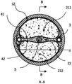
- Figure 1 is a cross-sectional view of a volume compensation device with a shell
- Fig. 2 is a longitudinal sectional view of a volume compensation device with a shell
- Fig. 5 is the sectional shape of brittle shell
- FIG. 6 schematic diagram of chemical reaction self-expanding device
- FIG. 7 schematic diagram of chemical reaction self-expanding device
- Figure 11 is a schematic diagram of the working principle of the volume compensation device with a shell
- Fig. 12 Contains a B material and a steel tube concrete compression member with a shell volume compensation device, longitudinal plan view;
- Figure 13 contains a B material and a steel tube concrete compression member with a shell volume compensation device, cross-sectional view;
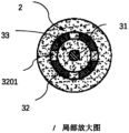
- Figure 14 contains a B material and a steel tube concrete compression member with a shell volume compensation device, a partial enlarged view of the cross section;
- Fig. 15 contains a kind of B material and a shell volume compensator in the steel tube concrete compression member of a shell volume compensator, longitudinal section view,
- Figure 16 contains a B material and a steel tube concrete compression member with a shell volume compensation device, a longitudinal plan view;
- Fig. 17 Contains a B material and six CFST compression members with shell volume compensation devices, longitudinal plan view;
- Fig. 18 Contains a B material and six steel tube concrete compression members with shell volume compensation devices, cross-sectional view;
- Fig. 19 Contains two B materials and a steel tube concrete compression member with a shell volume compensation device, longitudinal plan view;
- Figure 20 is a cross-sectional view of a CFST compression member containing two B materials and a shell volume compensation device
- Fig. 21 Contains two B materials and a CFST compression member with a shell volume compensation device, a partially enlarged view of the cross section;
- Fig. 22 Contains two B materials and two steel tube concrete compression members with shell volume compensation devices, longitudinal plan view;
- Figure 23 is a cross-sectional view of a CFST compression member containing two B materials and two shell volume compensation devices
- Fig. 24 Contains two B materials and two CFST compression members with shell volume compensation devices, partial enlarged view of the cross section;
- Fig. 25 Contains two B materials and four steel tube concrete compression members with shell volume compensation devices, longitudinal plan view;
- Fig. 26 is a cross-sectional view of a CFST compression member containing two B materials and four shell volume compensation devices;
- Fig. 27 Contains two B materials and four CFST compression members with shell volume compensation devices, partial enlarged view of the cross section:
- Fig. 28 Contains two B materials and a steel tube concrete arch compression member with a shell volume compensation device, longitudinal plan view;
- Figure 29 contains two B materials and a steel tube concrete arch compression member with a shell volume compensation device, cross-sectional view;
- Fig. 30 Contains two B materials and a CFST arch compression member with a shell volume compensation device, a partial enlarged view of the cross section;
- Figure 31 Contains three B materials and a steel tube concrete compression member with a shell volume compensation device, cross-sectional view;
- Fig. 32 Contains three B materials and a steel tube concrete compression member with a shell volume compensation device, a partially enlarged view of the cross section;
- Fig. 33 is a cross-sectional view of a CFST compression member containing three B materials and two shell volume compensation devices;
- Fig. 34 Containing three kinds of B materials and two CFST compression members with shell volume compensation devices, partial enlarged view of the cross section.
- Fig. 35 Contains three kinds of B materials and four steel tube concrete compression members with shell volume compensation devices, longitudinal cross-sectional view;
- Fig. 36 Contains three B materials and four steel tube concrete compression members with shell volume compensation devices, cross-sectional view;
- Fig. 37 Contains three kinds of B materials and four steel tube concrete compression members with shell volume compensation devices, cross-sectional half-sectional view;
- Figure 38 Steel pipe containing three cavities used as part A, cross-sectional view.
- Figure 39 A lattice column with three columns
- Figure 40 A lattice column with three columns.
- a volume compensation device with a shell including a pressure supply device and a support shell;
- the support shell is surrounded by a cavity, and there is a connecting channel between the cavity and the surrounding space area outside the support shell;
- the pressure supply device is in the cavity
- the pressure supply device can provide pressure to the medium in contact with it.
- Figures 1 to 4 Take Figures 1 to 4 as examples for illustration. These figures are for illustration only and do not constitute a limitation to the content of the invention.
- Figure 1 is regarded as a cross-sectional view of Figures 2 to 4, and Figure 1 is respectively related to Figures 2, 3 and Figure 4 combines three situations.
- the supporting shell is a steel pipe 32 with a hole 3201 on the pipe wall.
- One end of the pipe is a convex shell, and the other end of the pipe is blocked with a threaded plug 3202. 3202 can be removed and installed from the pipe 32.
- a pressure supply device 31 is installed in the cavity of the support shell 32 . During installation, the pressure supply device 31 is packed into the pipe from the end with the plug, and then the plug 3202 is screwed on.
- the support shell includes an upper part 321, a lower part 322 and a connection sleeve 323.
- the upper part 321 and the lower part 322 can be separated, and the two are connected together by a connection sleeve 323.
- the support shell is divided into upper and lower parts It is to be able to pack the pressure supply device 31 into the cavity of the supporting shell.
- the upper part of the supporting shell has a hole 3211, and the lower part has a hole 3221.
- the supporting shell is the same as that in Figure 3, and the pressure supply device is several spherical air bags or/and spherical air-liquid bags or/and solid elastomer spheres.
- the hole 3201 on the pipe wall in Fig. 1 and Fig. 2 is the connecting channel; the hole 3211 and the hole 3221 in Fig. 3 and Fig. 4 are also connecting channels.
- support shells include tubes, convex shells.
- the outer contour of the cross section of the pipe is convex, suitable for bearing the uniform normal pressure around; preferably, the outer contour of the cross section of the pipe is circular or elliptical.
- the supporting shell is a pipe
- the connecting channel connecting the regions, the cross-section of this channel is the same as the cross-section of the tube cavity.
- the convex shell used as a supporting shell is a spherical shell or an ellipsoidal shell with holes.
- the materials for making the pipe and the convex shell are metal, composite material and macromolecule material.
- the pipe and the convex shell are made of structural steel.
- pressurizing devices includes pressurizing devices, energy storage devices and pressurized energy storage devices.
- the energy storage device has the following characteristics,
- the apparent volume of the energy storage device becomes smaller, and the energy storage device absorbs energy; or/and, when the pressure on the outer surface of the energy storage device decreases, the apparent volume of the energy storage device increases, and the energy storage device absorbs energy. A device that releases energy.
- the selection range of the energy storage device includes air bags, gas-liquid bags, energy storage liquid bags, solid elastomer energy storage devices, and elastic shell energy storage devices.
- the feature of the energy storage liquid bag is that the liquid bag is connected with the accumulator through a pipeline, when the liquid pressure in the liquid bag increases, the liquid is squeezed into the accumulator; when the liquid pressure in the liquid bag decreases, The fluid in the accumulator flows out of the accumulator.
- the air bag is characterized in that the air bag is filled with compressed gas.
- the characteristic of the gas-liquid capsule is that the capsule is filled with liquefied gas, and part of the medium in the capsule is in gaseous state, while the other part is in liquid state.
- Said pressurizing device is characterized by the ability to vary or maintain the pressure between its outer surface and the medium in contact with it.
- the selection range of the pressurizing device includes a pressurized air bag, a pressurized liquid bag, a pressurized gas-liquid bag, and a self-expanding device.
- the self-expanding device is a type A self-expanding device; preferably, the type A self-expanding device is a type A self-expanding device; preferably, the type A1 self-expanding device is a type A1a or/ and a Type 1b self-expanding device.
- the self-expanding device is a Type B self-expanding device.
- the pressurized air bag is connected with an air pressure source through a pipeline, and the air pressure source can adjust the gas pressure in the pipeline and the air bag.
- the air pressure source is an air pump.
- the pressurized air bag becomes an energy storage device.
- the pressurized liquid bag is connected with a hydraulic source through a pipeline, and the hydraulic source can adjust the liquid pressure in the pipeline and the liquid bag.
- an accumulator is also connected to the pipeline of the pressurized liquid bladder. If the volume of the accumulator is small, the accumulator only plays a role in stabilizing the pressure, and the pressurized liquid bladder can still be regarded as a pressurized liquid bladder. ; If the volume of the accumulator is larger, the pressurized liquid bladder becomes a pressurized energy storage liquid bladder.
- the pressurized air-liquid bag is connected with the air pressure source or/and the hydraulic pressure source through the pipeline, and the air pressure source or/and the hydraulic pressure source can adjust the gas or/and liquid pressure in the pipeline and the air-liquid bag.
- the pressurized energy storage device has the following characteristics A and B,
- the characteristic A is,
- a pressurized energy storage device capable of changing or maintaining the pressure between its outer surface and the medium in contact with it;
- the characteristic B is,
- the apparent volume of the pressurized energy storage device becomes smaller; or/and, if the pressure of the surrounding flowable medium decreases, the pressurized energy storage device The apparent volume of the device increases.
- the selection range of the pressurized energy storage device includes a pressurized air bag, a pressurized air-liquid bag, a pressurized energy storage liquid bag, a type A self-expanding device and a type B self-expanding device.
- the Type A self-expanding device is a Type A1 self-expanding device; preferably, the Type A1 self-expanding device is a Type A1a or/and a Type A1b self-expanding device.
- the gas in the pressurized air bag and the pressurized air-liquid bag is compressible and has the function of energy storage, so they can be regarded as pressurized energy storage devices.
- the characteristic of the pressurized liquid bag is that the liquid bag is not only connected with the hydraulic pressure source through the pipeline, but also connected with the accumulator.
- the hydraulic source can adjust the liquid pressure in the pipeline; the accumulator stores and releases energy to stabilize the liquid pressure.
- the characteristics of the fluid-solid conversion pressure supply device are: (1) there is a fluid medium inside the pressure supply device, which is the main source of pressure generated by the pressure supply device; (2) the fluid medium increases with time, Convert from fluid to solid.
- the fluid-solid conversion pressure supply device is an energy storage liquid bag, a pressurized liquid bag or a pressurized energy storage liquid bag, and the fluid medium in the bag is a fluid-solid conversion material.
- the bladder device includes a bladder pressurization device, a bladder energy storage device and a bladder pressurization energy storage device.
- the bladder pressurization devices include pressurized air bladders, pressurized liquid bladders, and pressurized gas-liquid bladders;
- Bladder energy storage devices include air bladders, gas-liquid bladders and energy storage liquid bladders
- Bladder pressurized energy storage devices include pressurized air bladders, pressurized air-liquid bladders, and pressurized energy storage liquid bladders.
- the bladder pressure supply device includes common bladders, upper limit bladders, lower limit bladders and double limit bladders.
- the common capsules include common air capsules, common air-liquid capsules, and common liquid capsules;
- the upper-limit capsules include upper-limit air capsules, upper-limit gas-liquid capsules, and upper-limit liquid capsules;
- the lower-limit capsules include lower-limit air capsules, lower-limit gas-liquid capsules, and lower-limit liquid capsules.
- the double-limited sac includes a double-limited air sac, a double-limited air-liquid sac, and a double-limited liquid sac.
- the normal capsule is capable of changing apparent volume by undergoing a shape change and/or a size change.
- the walls of the ordinary bladder are made of materials that are prone to bending deformation and tensile deformation; preferably, the wall material of the ordinary bladder is rubber.
- the walls of the common air bag, common air-liquid bag, and common liquid bag are all made of materials that are prone to bending deformation and tensile deformation; preferably, the common air bag, common air-liquid bag, and The wall material of common fluid bladder is rubber.
- one of the preferred schemes is to inflate the air bag or the air-liquid bag to the designed level only when the ordinary air bag or the ordinary air-liquid bag is in the cavity of the supporting shell.
- pressure value When the air pressure reaches the design value, the outer wall of the air bag or the air-liquid bag is in close contact with the inner wall of the support shell and there is a contact pressure stress, and the air pressure in the air bag or the air-liquid bag is almost equal to that between the outer surface of the air bag or the air-liquid bag and the support shell. Normal stress between inner surfaces.
- a barrier is placed at the hole in the inner wall of the support shell to prevent the capsule wall from being squeezed into the hole.
- the barrier is a sheet-like object; preferably, the barrier is a plastic sheet.
- the upper limit capsule has the following characteristics: if both the inner and outer surfaces of the capsule wall are only in contact with fluid, and the internal pressure is higher than the external pressure; then,
- the apparent volume and external shape of the cap capsule are relatively stable, and no longer change significantly with the increase of the pressure difference.
- the volume of the upper limit capsule is changed by changing the shape; preferably, the capsule wall material is a material that can be bent but has little tensile deformation; preferably, the production method of the capsule wall material is Apply impermeable materials such as curable rubber on the high-strength fiber fabric.
- the upper limit capsule is wrapped with a restriction sleeve outside the ordinary capsule, and the restriction sleeve is made of high-strength fibers.
- the restriction sleeve When the ordinary capsule is inflated to be in close contact with the restriction sleeve, the restriction sleeve will limit the expansion of the capsule wall.
- the bladder wall and the constraint sleeve When the internal fluid pressure is increased, the bladder wall and the constraint sleeve will jointly resist the pressure of the fluid in the bladder, and the expansion of the bladder will be limited.
- the upper-limit capsule is an upper-limit air capsule or an upper-limit gas-liquid capsule; preferably, when the upper-limit capsule reaches the volume upper limit, its shape and size are suitable for being put into the cavity of the support shell.
- an upper limit air bag or an upper limit air-liquid bag is placed in the cavity of the support shell;
- a plurality of upper-limit air bags or upper-limit air-liquid bags whose air pressure meets the requirements are placed in the cavity of the support shell;
- the support shell is a pipe with a circular cross-section, and a circular tubular upper limit air bag or a circular tubular upper limit air-liquid bag is placed inside the pipe as an energy storage device, see Figures 1 to 3.
- the upper limit air bag 31 or the upper limit The length of the air-liquid bag 31 is lower than the length of the supporting shell (Fig. 2), and when the air-liquid bag 31 or the air-liquid bag 31 reaches the upper limit volume, the outer diameter of the cross section is slightly smaller than the inner diameter of the pipe.
- a plurality of circular tube-shaped upper-limit air cells or upper-limit gas-liquid cells are placed inside the tube, and the total length of the gas cells or gas-liquid cells is less than the support shell.
- the support shell is a pipe with a larger diameter, and a plurality of spherical upper-limit gas bags or spherical upper-limit air-liquid bags are placed inside the pipe, as shown in Figure 4.
- at least one of the two ends of the pipe is not sealed. Blocking; Preferably, both ends of the pipe are blocked;
- the diameter of the spherical upper limit air bag or the upper limit gas-liquid bag is slightly smaller than the inner diameter of the support shell; preferably, when the volume upper limit is reached, the diameter of the spherical upper limit air bag or the upper limit gas-liquid bag is the same as
- the ratio of the inner diameter of the pipe is between 0.5 and 07, or between 0.7 and 0.95.
- the support shell is a spherical shell or an ellipsoidal shell, and one or more spherical upper-limit air bags or upper-limit air-liquid bags are placed in the cavity of the shell.
- the lower limit capsule has the following characteristics: when the internal and external pressure difference is negative, the shape or/and apparent volume of the capsule is the shape and volume required by the design.
- the internal and external pressure difference is the difference between the fluid pressure inside the capsule and the fluid pressure outside the capsule.
- a support of a certain shape is placed inside the lower limit capsule, and the shape of the support determines the final shape of the capsule wall under the action of external high pressure.
- the shape of the support includes three-leaf, four-leaf, dumbbell-shaped, round, etc., see Figure 8.
- the support is three-leaf, four-leaf, dumbbell, It is made of circular steel pipe, and there are many small holes distributed on the wall of the steel pipe, through which the gas can pass; preferably, the diameter of the small holes is between 0.1-1mm.
- the tangential elongation of the capsule wall material of the lower limit capsule is very small, and dumbbell-shaped, trilobate, and quatrefoil-shaped supports (see Figure 8) are placed inside, and the section perimeter of the capsule will be slightly greater than or Equal to the perimeter of the cross-section of the support.
- the lower-limited capsule is actually a double-limited capsule.
- the tangential elongation of the capsule wall material is very large (such as rubber), and the support can also be round, Triangle, square and other shapes.
- Fig. 9 and Fig. 10 are the schematic diagrams of putting the trilobate-shaped support into the capsule.
- the static pressure on the outer surface of the surrounding capsule wall presses the capsule wall 312 to the surface of the support 311, the shape of the wall capsule 312 and the support Object 311 is the same (Fig. 9); when the fluid pressure in the capsule is greater than the surrounding static pressure, the lower limit capsule expands; when the capsule wall is fully expanded, the section will be approximately circular, as shown in Fig. 10.
- the pressure supply device is a double-limit air bag.
- the dual-limit airbag has the characteristics of the upper limit airbag and the lower limit airbag at the same time, that is, it has the following two characteristics:
- the pressure difference is the difference between the fluid pressure inside the capsule and the fluid pressure outside the capsule;
- the shape of the bladder is elongated, all or almost all materials of the bladder are of the same type, and there is no obvious section between the parts of the bladder.
- the elongated integrated bladder is Rubber bladder.
- It includes a flexible pipeline and blocking devices at both ends, and the flexible pipeline is connected with the blocking devices at both ends.
- the material of the flexible pipeline can be bent at least in the circumferential direction, and the bending stiffness is close to 0; the elongation strain of the material of the flexible pipeline in the circumferential direction of the pipeline is less than a given value ⁇ ; Preferably, the elongation strain of the material of the flexible pipeline in the circumferential direction of the pipeline is greater than a given value ⁇ ; preferably, the ⁇ is less than or equal to 5%.
- the flexible pipeline is a rubber tube or a flexible PVC tube that can be stretched in the circumferential direction.
- the flexible pipeline is a thin-walled metal tube with a wall thickness close to the thickness of the side wall of a can; preferably, the cross-sectional shape of the bag is trilobal or quatrefoil before the bag is filled with fluid.
- the pressure supply device is a solid elastic body energy storage device.
- the solid elastic body energy storage device is a solid elastic body, and the material of the elastic body is a material with high elastic deformation such as rubber and polyurethane.
- the pressure supply device is an elastic shell energy storage device.
- the characteristic of the elastic shell energy storage device is that the shell is made of elastic material, and the shell surrounds a closed cavity; when subjected to the pressure of the surrounding liquid, at least a part of the shell is deformed.
- This shell mainly stores energy by bending and deforming.
- the self-expanding device is a device whose apparent volume can expand, or a device whose apparent volume can expand under certain conditions.
- Type A self-expanding device includes a skin and a gas generating device.
- the skin is a closed device made of impermeable or almost impermeable material that can change the apparent volume, or a closed device that can change the apparent shape and apparent volume; Impermeable means that gases and/or liquids under pressure are not able to seep through the skin.
- the gas generating device can generate gas, which squeezes the outer skin from the inside, increasing the apparent volume of the self-expanding device.
- the outer skin of the Type A self-expanding device is a closed device made of polymer material, and when it is fully inflated, its shape is tubular, spherical or ellipsoidal; preferably, the polymer material is rubber.
- the outer skin of the Type A self-expanding device is a non-circular cross-section metal thin-wall tube with both ends blocked.
- the shape of the thin-walled tube changes and the apparent volume increases.
- the gas generating device in the Type A self-expanding device contains at least two materials, and the two materials are usually isolated from each other; when a certain condition is met, the two materials mix with each other, a chemical reaction occurs, and gas is generated, and the gas pushes The skin swells.
- the two materials are mixed to generate gas.
- the two materials are sodium bicarbonate and a liquid containing hydrogen ions respectively.
- the self-expanding A safety valve is installed on the device to ensure that the gas pressure is maintained near the preset value. When the gas pressure exceeds the preset pressure value of the safety valve, the gas is discharged from the valve port. When the gas pressure is lower than the preset value, the safety valve is closed .
- the two gas-generating materials are water and polyurethane grouting fluid respectively.
- a type 1a self-expanding device has chemical component a in the closed space surrounded by the outer skin, and a device with chemical component b wrapped in a brittle shell.
- chemical components a and b are mixed, gas can be generated.
- the expansion mechanism is: when the outer skin of the self-expanding device is squeezed, the outer skin will squeeze the brittle outer shell inside, causing it to rupture.
- the chemical components a and b are mixed to generate gas, which pushes the skin to expand.
- the brittle shell is a tube 313 made of brittle material, closed at both ends, and non-circular in section. Further, the section of the glass tube is oval, or rectangular, or a combination of a rectangle and two semicircles, see Figure 5.
- the brittle material is a brittle polymer material or glass; preferably , the brittle polymer material is brittle plastic.
- the outer skin of the self-expanding device is a rubber tube 310 with both ends closed, as shown in Fig. 6, inside which is placed chemical composition a (312) and a glass tube 313 with both ends closed and a rectangular section, and the liquid filled in the glass tube is Chemical composition b (314).
- the rubber tube squeezes the Radix Radix 313 inside, causing it to rupture, and then the liquid chemical component a (314) flows out and reacts with component b (312) to generate gas.
- component a is sodium carbonate
- component b is hydrochloric acid.
- component a is polyurethane grout
- component b is water
- the two are mixed and foamed, resulting in volume expansion, and the resultant has a certain strength after curing.
- the masses of the chemical components a and b are determined according to the mass of the production gas, which is determined according to the ambient temperature, the volume of the gas and the pressure of the gas.
- a safety valve is provided on the self-expanding device, and when the gas pressure exceeds a preset value, part of the gas is discharged to ensure that the pressure does not exceed a specified value.
- a type 1b self-expanding device a brittle shell capsule
- a and B placed in the confined space of the A1b type self-expanding device.
- the shells of the devices A and B are both brittle shells.
- a chemical component a is placed inside the device A, and another chemical component is placed inside the device B.
- a chemical component b that can generate gas when components a and b are mixed.
- the self-expanding device is a PVC pipe 310 with both ends closed, as shown in Figure 7.
- the brittle plastic pipe 311 is filled with chemical
- the liquid 312 with composition a the brittle plastic tube 313 is filled with liquid 3214 with chemical composition b.
- the brittle plastic tubes 3211 and 3213 will rupture successively or simultaneously.
- the liquids 314 and 312 in the two brittle plastic tubes flow out, a reaction reaction occurs after mixing, and the gas generated expands outward from the rubber tube squeezed from the inside.
- component a is sodium carbonate solution and component b is hydrochloric acid.
- component a is polyurethane grouting fluid
- component b is water
- the two are mixed and foamed to produce volume expansion, and the resultant has a certain strength after curing.
- the B-type self-expanding device is made of shape memory alloy, or the material used includes shape memory alloy.
- the shape of the memory alloy changes, and then the volume of the self-expanding device changes.
- the volume enclosed by the outer surface of the self-expanding device is the minimum or close to the minimum; when the temperature is in the T2 range, the external volume of the device is the largest or close to the maximum; the internal temperature of the composite structure is not in T1 Within the interval temperature range, but within the T2 interval temperature range;
- the memory alloy self-expanding device Before being used to apply pressure to the material of part B in the cavity surrounded by part A, the memory alloy self-expanding device is placed in the temperature range of T1; after being placed in the cavity surrounded by part A, since the temperature is in the temperature range of T2, The external volume of the device expands and squeezes the material of part B.
- a commonly used self-expanding device is a tube made of shape memory alloy and closed at both ends.
- T2 the temperature enters the range of T2
- the cross-sectional shape of the pipe wall changes, and the surrounding volume on the outer surface expands, which exerts pressure on the cement-containing material;
- the cross-sectional shape of the pipe wall changes, at least one section of the pipe wall on the cross-section will Bending; due to the ability of the pipe wall to store a large amount of elastic energy when it bends, this device also has an energy storage function.
- Another self-expanding device is made of flexible material and memory alloy. When the shape of the memory alloy changes, the flexible material changes together, thereby changing the volume surrounded by the outer surface of the self-expanding device.
- a method for manufacturing a volume compensating device with a shell which is characterized in that the volume compensating device with a shell can be manufactured by this method.
- a method for making a volume compensation device with a shell comprising making a supporting shell and making a pressure supply device for the device.
- the pressure supply device is installed in the cavity of the support shell.
- a method for providing pressure to the surrounding medium using a volume compensation device with a shell characterized in that,
- the fluid-solid conversion material is present between the inner wall of the support shell and the outer surface of the pressure supply device; or/and,
- the fluid-solid transfer material exists in at least a part of the surrounding space outside the support shell;
- the device When the fluid-solid conversion material is in a flowable state, the device has the following characteristic A or/and characteristic B,
- the property A is,
- the fluid-solid conversion material flows into the cavity surrounded by the support shell through the channel, squeezing the pressure supply device in the cavity , making the apparent volume of the pressure supply device smaller; or/and,
- the characteristic B is,
- the fluid-solid conversion material and the supporting shell form a composite shell, and the composite shell resists the pressure of the external medium as a whole.
- the support shell 32 has a hole 321
- the pressure supply device 31 is located in the cavity surrounded by the support shell 32, and there is a fluid-solid conversion material 331 between the outer surface of the pressure supply device and the inner wall of the support shell.
- a fluid-solid conversion material 333 exists in the outer peripheral space of the support shell 32.
- the fluid-solid conversion materials 331, 332 and 333 in the different regions are the same material.
- the fluid-solid conversion material surrounds the entire outer surface of the support shell 32; preferably, only a part of the outer surface of the support shell is in contact with the fluid-solid conversion material.
- a composite structure comprising parts A, B and C; wherein
- Part A is surrounded by a cavity and is made of solid material
- Part B consists of a fluid-solid transition material, which is a material capable of changing from a flowable state to a solid state;
- Part C is one or more volume compensating devices with a shell, each volume compensating device with a shell includes a support shell and a pressure supply device, and the pressure supply device is in the cavity of the support shell;
- the volume compensating device with shell and the material of part B are located in the cavity surrounded by part A.
- the fluid-solid conversion material in the gap between the outer surface of the pressure supply device and the inner surface of the support shell or/and in the outer peripheral area of the support shell; preferably, the fluid-solid conversion material and the part B material are The same material, or the same material as a Part B material.
- the A part is surrounded by a cavity.
- the part A is surrounded by two or more cavities, and the cavities have the following characteristics:
- At least two cavities are in communication with each other; the communication means that there is a connecting channel between the two cavities, and the medium in a flowable state can flow from one cavity to the other; or/and,
- At least two cavities are isolated from each other; the isolation means that there is no connecting channel between the two cavities.
- the part A includes a pipe and the blocking device at both ends thereof.
- the cross section of the blocking device at at least one end is larger than the cross section of the pipe; preferably, the cross section of the blocking device at at least one end is The enclosing figure of the outer contour line of the section is the same as the enclosing figure of the outer contour line of the cross section of the pipe.
- the pipe is a steel pipe or an FRP pipe.
- the A part is a spherical or ellipsoidal shell.
- the cavity 2.2 in the three-cavity steel pipe is adjacent to the cavity 2.1 and the cavity 2.3 respectively, wherein the cavity 2.1 and 2.2 are connected, and there are holes on the partition 12.2 between the two 12.2.1; the cavities 22. and 2.3 are isolated.
- the cavities of the column limb 12.1, column limb 12.2 and column limb 12.3 in the three-limb lattice column are isolated from each other, Each cavity is filled with concrete.
- the pipe is not connected to the column limb.
- the material in part B is a fluid-solid conversion material, and the selection range of the fluid-solid conversion material includes but is not limited to the following:
- the cement-based materials include cement mortar, reactive powder concrete (RPC), normal-strength concrete (NHSC), high-strength concrete (HSC), and ultra-high-strength concrete (UHSC);
- the polymer material is a polymer emulsion
- the polymer material is a polymer material capable of curing itself, including epoxy resin;
- the self-curable polymer material includes epoxy resin
- the part B material is a mixture of polymer material and solid powder; preferably, the part B material is a mixture of polymer material and solid particles; preferably, the part B material is a polymer material, solid Mixtures of powders and solid particles;
- the solid powder is metal powder or inorganic non-metallic material powder; the solid particles are metal particles or inorganic non-metallic material particles; preferably, the inorganic non-metallic material powder and particles are respectively stone powder and pebbles.
- each B-part material is a fluid-solid transition material.
- said Part B material has at least one of the following characteristics A and B:
- the B j material has relatively high fluidity
- the end moment of the flowable state of the B j material is later than or equal to the end moment of the flowable state of the B i material, and earlier than the volume shrinkage turning point of the B i material; or,
- the end time of the flowable state of the B j material is later than or equal to the time when the volume shrinkage turning point of the B i material occurs.
- At least one cavity surrounded by part A there is at least one i, 1 ⁇ i ⁇ M, and the corresponding B i material has one or two or three of the following characteristics A, B and C ,
- the B i material When the B i material is in the flowable state stage, in one of the time periods, or multiple time periods, or all stages, at least the B i material is subjected to compressive stress among all the B part materials;
- the B i material After the B i material is solidified, at least the B i material is subjected to compressive stress or precompressive stress or residual precompressive stress among all the B part materials.
- At least in one cavity surrounded by said part A there is also a simplified pressurization device capable of changing and/or maintaining the compressive stress of the B material in the cavity surrounded by part A.
- the selection range of the simplified pressurization device includes a pressurization piston, a pressurization pipeline and the medium therein, and a retarding pressurized liquid bladder.
- the pressurizing piston is a rod of solid material with a smooth surface. It passes through the piston hole on part A and extends into the cavity surrounded by part A. The pressurizing piston and the piston hole are sealed; the pressurizing piston can Move along its length to increase its pressure by displacing the space occupied by the Part B material, or/and decrease the pressure by giving way to the space it occupies.
- the pressurized pipeline and the medium therein are pipelines connected to the external pressure source and the cavity surrounded by part A, and the medium in the pipeline is the material of part B in a flowable state; when the pressure source increases the pressure , the material of part B in the pipeline enters the cavity surrounded by part A;
- the characteristic of the retarding pressurized liquid bag is that the liquid bag is located in the cavity surrounded by part A; the liquid bag is filled with a slow-setting fluid-solid conversion material, and the moment of solidification is later than the moment of the end of pressurization.
- the member has an axis over one, or more or all of its lengths of the combined structure
- the axis has at least one of the following characteristics
- the figure surrounded by the outer contour of the cross section of the component is a figure surrounded by straight lines or/and curves; preferably, the figure is Convex; preferably, the figure is a convex polygon; preferably, the figure is a convex curve figure; preferably, the figure is a circle or an ellipse; preferably, the figure is a rounded polygon .
- At least one of the cavities surrounded by the outer contour of the cross section is a straight line or/and A figure enclosed by a curve; preferably, the figure is convex; preferably, the figure is a convex polygon; preferably, the figure is a convex curve figure; preferably, the figure is a circle or An ellipse; preferably, the figure is a polygon with rounded corners.
- the shape and size of the cross-section are respectively the same at different positions in the length direction;
- the cross-sections at different positions in the length direction are similar in shape but different in size;
- the composite structural member is a cylindrical compression member with a linear axis and only one cavity; preferably, the composite structural member is a compression member with an arched curve axis and only one cavity; the The shape and size of the cross-section of the arched compression member do not change along the length direction.
- At least one cavity surrounded by part A there is at least one i and one j, where 1 ⁇ i ⁇ M, 1 ⁇ j ⁇ M, i ⁇ j, and the corresponding B i material is adjacent to B j material; two The relationship between them has one of the following properties,
- the isolation device is a thin iron cylinder
- the B i material is on the inside of the cylinder
- the B j material is on the outside of the cylinder; preferably, the upper and lower ends of the cylinder are sealed.
- the upper end is left with a feed port, and any boundary surface of the B i material is not in direct contact with the B j material; preferably, the upper end of the cylinder is not blocked, and the upper end of the B i material is directly connected to the upper end of the B j material. touch.
- a method for making a combined structure comprising obtaining part A, putting one or more volume compensating devices with a shell into the cavity surrounded by the part A, filling the cavity with material of part B, and filling the cavity with The part B material applies pressure.
- the material of the part B is a fluid-solid conversion material, and when filling the cavity surrounded by the part A, at least a part of the material of the part B is in a flowable state;
- the shelled volume compensation device includes a pressure supply device and a support shell. When appropriate, fill the gap between the outer surface of the pressure supply device and the inner surface of the support shell with a fluid-solid conversion material.
- the fluid-solid conversion material in a flowable state is filled at least between the outer surface of the pressure supply device and the inner surface of the support shell in the void; or/and,
- the part B material in the peripheral area near the outer surface of the support shell passes through the support shell into the gap between the outer surface of the pressure supply device and the inner surface of the support shell.
- the A part is surrounded by a cavity.
- the part A is surrounded by two or more cavities, and the cavities have the following characteristics:
- At least two cavities are in communication with each other; the communication means that there is a connecting channel between the two cavities, and the medium in a flowable state can flow from one cavity to the other; or/and,
- At least two cavities are isolated from each other; the isolation means that there is no connecting channel between the two cavities.
- the types of the materials of the B part include the following four categories:
- the cement-based materials include cement mortar, reactive powder concrete (RPC), normal-strength concrete (NHSC), high-strength concrete (HSC), and ultra-high-strength concrete (UHSC);
- the polymer material is a polymer emulsion
- the polymer material is a polymer material capable of curing itself, including epoxy resin;
- the self-curable polymer material includes epoxy resin
- the part B material is a mixture of polymer material and solid powder; preferably, the part B material is a mixture of polymer material and solid particles; preferably, the part B material is a polymer material, solid Mixtures of powders and solid particles;
- the solid powder is metal powder or inorganic non-metal material powder; the solid particles are metal particles or inorganic non-metal material particles; preferably, the inorganic non-metal material powder and particles are stone powder and pebbles, respectively.
- part B At least in one cavity surrounded by part A, there are M kinds of materials of part B, respectively B 1 , B 2 ... B i , B i+1 ... B M materials, which respectively occupy different spatial regions.
- said Part B material has at least one of the following characteristics A and B:
- the B j material has relatively high fluidity
- the end moment of the flowable state of the B j material is later than or equal to the end moment of the flowable state of the B i material, and earlier than the volume shrinkage turning point of the B i material; or,
- the end time of the flowable state of the B j material is later than or equal to the time when the volume shrinkage turning point of the B i material occurs.
- At least one cavity surrounded by part A there is at least one i, 1 ⁇ i ⁇ M, and the corresponding B i material has one or two or three of the following characteristics A, B and C ,
- the B i material When the B i material is in the flowable state stage, in one of the time periods, or multiple time periods, or all stages, at least the B i material is subjected to compressive stress among all the B part materials;
- the B i material After the B i material is solidified, at least the B i material is subjected to compressive stress or precompressive stress or residual precompressive stress among all the B part materials.
- B M In the cavity surrounded by the part A, there is a B M material inside the support shell or/and in the surrounding area outside the support shell of the volume compensation device with a shell; when 1 ⁇ i ⁇ M-1, B M The end time of the flowable state of the material is later than or equal to the end time of the flowable state of any Bi material.
- the B material in the cavity surrounded by the A portion has the following properties:
- the pressure supply device in the shell volume compensation device expands, pushing the B M material in the support shell to flow out through the hole, filling the volume change in the cavity surrounded by part A due to the contraction of the B i material.
- spacers are provided between the different Part B materials.
- the isolating device is made of impermeable material to prevent mixing of components of different B-part materials.
- the material of the isolating device and the B-part material have better bonding properties, In order to prevent the shear capacity of the material of part B and the isolation device from being too low at the interface, which will affect the bearing capacity of the component.
- the material for the isolation device is selected as a metal sheet.
- the spacer has satisfactory permeability so that different Part B materials can penetrate into the material of the spacer, maintaining a good bond with the spacer.
- the material of the spacer is mesh Shape material;
- the mesh material is a metal mesh.
- the metal mesh is installed on a fixing frame, and the fixing frame is installed in the cavity surrounded by the A part.
- the spacer is deformable so that the volume of the area it encloses changes.
- there is only one shelled volume compensating device in the cavity enclosed by part A see FIGS. 12 to 14 .
- the position of the volume compensation device with a shell is axisymmetric about a certain straight line.
- said part B material is cement mortar, preferably said part B material is reactive powder concrete.
- the pressure supply device in the volume compensation device with the shell pushes the B2 material in contact with it to flow out of the hole in the supporting shell to fill up the B1 Volume change due to material shrinkage.
- the B1 and B2 materials have one of the following two characteristics: (1) The end time of the flowable state of the B2 material is later than or equal to the end time of the flowable state of the B1 material and earlier than the B1 material The moment when the turning point of volume shrinkage appears; (2) The end moment of the flowable state of the material B2 is later than or equal to the moment when the turning point of volume shrinkage of the material B1 appears.
- the B2 material is retarded mortar or active powder concrete or retarded epoxy resin; preferably, the B1 material is concrete; preferably, the B1 material is B2 material and coarse aggregate mixture.
- the pressure supply device in the shell volume compensation device pushes the B3 material in contact with it from the hole of the supporting shell flow out, filling the shrinkage volume of B1 or/and B2 material.
- the B 1 , B 2 and B 3 materials have one of the following three characteristics:
- the end moment of the flowable state of the B2 part material is later than the moment when the volume shrinkage turning point of the B1 material occurs; or/and,
- the end time of the flowable state of the B3 material is later than the end time of the flowable state of the B2 material, and earlier than the volume shrinkage turning point of the B2 material;
- the end moment of the flowable state of the B2 part material is later than the moment when the volume shrinkage turning point of the B1 material occurs; or/and,
- the end time of the flowable state of the B3 part material is later than the time when the volume shrinkage turning point of the B2 material occurs;
- the end time of the flowable state of the B2 part material is later than or equal to the end time of the flowable state of the B1 material, and earlier than the volume shrinkage turning point of the B1 material; or/and,
- the end time of the flowable state of the B3 material is later than or equal to the end time of the flowable state of the B2 material, and earlier than the volume shrinkage turning point of the B2 material.
- the end time of the flowable state of the B2 part material is later than the moment when the volume shrinkage turning point of the B1 material occurs; or/and, the end time of the flowable state of the B3 part material is later than the volume shrinkage of the B2 material The moment of turning point.
- the ultimate bearing capacity of the supporting shell should meet the following requirements: when the combined structure is in the limit state of bearing capacity, it is required that the supporting shell withstand the maximum compressive stress of the surrounding medium not less than the surrounding medium acting on the support pressure on the shell wall.
- the concrete-filled steel tube axial compression member is taken as an example for illustration. Assume that part A of the combined structure is a steel pipe with a circular cross-section, and the supporting shell is a circular steel pipe with holes in the pipe wall. When the composite structure is destroyed due to axial compression, the entire structure undergoes axial compression and radial expansion. The material B in the cavity surrounded by part A bulges radially, which is the main factor causing the entire structure to bulge outward. Part A enters yield due to axial compression and tangential tension. In this failure mode, the Avoid the solidified fluid-solid transition material around the support shell becoming a weak area due to insufficient radial bearing capacity or insufficient radial stiffness.
- the equivalent maximum radial compressive stress on the outer surface of the steel pipe of the support shell is the combined Radial compressive stress of material B when the structure fails. It is approximately considered that the maximum radial compressive stress of the B material is the radial compressive stress on the inner surface of the A part when the A part yields or when the combined structure reaches the limit of the bearing capacity.
- the radial bearing capacity of the supporting shell is determined by an equivalent method.
- the steel pipe of the support shell is equivalent to a steel pipe without holes in the wall.
- the equivalent method is to take a length of the steel pipe with holes in the wall, calculate its radial bearing capacity, and then The radial bearing capacity at different positions in the length direction is averaged.
- the length, outer diameter and average radial bearing capacity of the equivalent pipe wall without holes are the same as those of the steel pipe with holes in the pipe wall.
- Another equivalent method is to combine the solidified fluid-solid conversion material within a certain radius around the support shell and the support shell with holes in the pipe wall to form a new structure called a composite shell. Calculation Radial bearing capacity of the composite shell. Preferably, when determining the scope of the composite shell, the fluid-solid conversion material in the steel pipe cavity is also taken into consideration.
- the maximum compressive stress and the maximum radial stiffness that the composite shell can bear are much greater than the maximum pressure that the outer surface of the pressure supply device in the cavity of the support shell can withstand and the maximum stiffness of the pressure supply device.
- the stiffness is Refers to: the radial pressure increment acting on the outer surface of the device, divided by the radial displacement caused by the pressure increment, and then divided by the outer diameter of the device.
- the composite shell composed of the fluid-solid conversion material and the supporting shell can withstand the maximum pressure exerted by the surrounding medium, which is much higher than when the pressure supply device works alone The pressure provided by the pressure supply device to the surrounding medium.
- the apparent bulk modulus and apparent bulk deformation modulus of the pressure supply device are respectively much lower than the bulk modulus and bulk deformation modulus of the material of part B at any stage, and the said any stage refers to the whole process
- the whole process means the process of changing the material from a flowable state to a solid state reaching its ultimate strength
- the simplified pressurizing device is installed before or after filling the material of part B into the surrounding cavity of A.
- the simplified pressurizing device is a retarding pressurized liquid bag
- the liquid bag should be installed in the cavity before filling part B into the cavity surrounded by A.
- the simplified pressurizing device is a pressurizing piston, or a pressurizing pipeline and the medium in it, install the pressurizing piston or pressurizing pipeline after completing the filling of part B materials and installing the blocking plate.
- the pressurization includes applying a variable pressure to the medium, or/and maintaining a constant or substantially constant pressure on the medium.
- the pressure supply device is a pressurization device or a pressurized energy storage device.
- B In the gap between the support shell and the pressure supply device In, and around the retaining device of the shelled volume compensation device are B i materials.
- the strength preset value refers to that when the strength of the Bi material is lower than the preset value, if the pressure of the pressure supply device is changed, the change of the pressure of the pressure supply device will cause the near hole on the support shell The stress field of the B i material changes, and this change will cause the damage of the B i material near the hole of the supporting shell or reduce the long-term strength.
- the strength design value means that when the strength reaches the design value, the composite shell formed by the Bi material and the support shell has sufficient load-bearing capacity to resist the pressure of the surrounding medium; when the pressurization device or pressurized energy storage is removed After the pressure applied by the device, the change of the stress field will not reduce the long-term strength of the Bi material near the hole of the support shell, nor will it damage the Bi material there.
- the pressure supply device is a pressurized device or a pressurized energy storage device
- the pressure supply device is an energy storage device or a pressurized energy storage device.
- the Bi material is filled in the gap between the inner wall of the support shell of the device A and the pressure supply device, and in the area around the device A.
- the B j material is filled in the gap between the inner wall of the supporting shell of the device B and the pressure supply device, and in the area around the device B.
- the pressure method is as follows.
- said shelled volume compensating Devices A and B are also in this region.
- the compressive stress applied by the pressurizing device or the pressurized energy storage device in the device A to the Bi material is constant, or fluctuates within a preset range;
- the compressive stress applied by the pressurizing device or the pressurized energy storage device in the holding device A to the B i material is constant, or fluctuates within a preset range; preferably, the pressurized energy storage device in the holding device B is on B j
- the compressive stress applied to the material is constant, or fluctuates within a preset range.
- the pressure applied to the Bi material by the pressure supply device in the shell volume compensation device A is not restricted or the pressure is relieved;
- the compressive stress applied to the B i material by the pressure supply device in device B is not restricted or the pressure is relieved.
- the selection range of the pressurizing device includes a pressurizing piston, a pressurizing pipeline and the medium therein, and a retarding pressurized liquid bladder.
- the pressure supply device is an energy storage device or a pressurized energy storage device.
- B i material the area around the shell is filled with B j material.
- the pressure method is as follows.
- the pressure supply device in the volume compensation device with a shell is selected as a pressurized energy storage device, then use the pressurized energy storage device to pressurize the B i material, or/and use a simplified pressurization device to pressurize the B j material Pressurize.
- said shelled volume compensating The device and said simplified pressurization device are also located in this area.
- the pressure supply device in the volume compensation device with shell is selected as the energy storage device, the pressure applied by the simplified pressurization device to the B j material is kept constant, or the simplified pressurization device is kept surrounded by the A part
- the volume occupied in the cavity is substantially constant;
- the pressure supply device in the volume compensation device with shell is selected as a pressurized energy storage device, then keep the pressure exerted by the pressurized energy storage device on the Bi material constant, or fluctuate within a preset range ; and keep the pressure exerted by the simplified pressurizing device on the B j material constant, or keep the volume occupied by the simplified pressurizing device in the cavity surrounded by the A part substantially constant.
- the pressure applied to the Bi material by the pressure supply device in the volume compensation device with the shell is not restricted or the pressure is relieved;
- the compressive stress applied to the B j material by the simplified pressurizing device is not restricted or the pressure is released.
- the steel tube concrete composite structure is an axial compression member, as shown in Figure 12-14.
- Part A includes an upper block plate 110, a flange 111, a steel pipe 12 and a lower block plate 13.
- the flange 111 is welded on the upper end of the steel pipe 12, and the lower block plate is welded on the lower end of the steel pipe 12.
- Bolts are used to connect the upper block plate and the flange, and the bolt holes 1101 on the upper block plate face the bolt holes 1111 on the lower block plate. Construction holes 1102 and exhaust holes are processed on the upper block plate. hole 1103.
- a volume compensation device with a shell In the cavity of the steel pipe, a volume compensation device with a shell is installed at the axial position; the rest of the cavity is filled with reactive powder concrete (RPC for short).
- the volume compensation device with shell is a circular tube-shaped air bag placed inside a steel pipe with holes.
- the structural form is shown in Figure 1 and Figure 3.
- the end face of the upper part of the supporting shell is in close contact with the end face of the lower part, so that the supporting shell can be moved in the axial direction.
- the withstand pressure reaches the maximum value.
- the airbag is an ordinary airbag.
- a plastic sheet is pasted on the tube wall inside the support shell, so that the plastic sheet covers the circular hole on the tube wall.
- the support shell and the connecting sleeve are connected in a threaded manner; preferably, the support shell and the The connecting sleeves are connected by glue. Inflate the airbag, and the inflation will end when the air pressure reaches 8MPa.
- the pressurizing device can choose a grouting pump, a concrete pump or other pressurizing devices.
- One of the methods is to saw off the construction pipeline from the root.
- the volume of RPC shrinks before and after solidification. If the one-time pressurization method is used without using the shell volume compensation device, when the volume of RPC shrinks, it will The pressure that causes the RPC to decrease or even disappear. If the intermittent pressurization method is used without using the shell volume compensation device, the pressure caused by the volume contraction when the B material is in a flowable state can be eliminated reduce, but cannot eliminate the pressure drop caused by the volume contraction of material B after solidification, because the material B in the long and thin pipeline can basically no longer flow after solidification.
- the one-time compression scheme is applicable if the cross-section is small or/and the volume shrinkage of the B material is low. Under this condition, using a volume compensation device with a shell to maintain the pressure can ensure that the retained precompressive stress reaches the preset value after material B reaches its final strength.
- the technical effect of this scheme is that when the applicable conditions are met, the construction method is simple and the devices used are simple.
- the applicable condition of the intermittent pressurization scheme is that the volume shrinkage rate of material B is high before solidification, and the volume shrinkage rate is very low after solidification.
- the pressure supply device in the volume compensation device with shell is an energy storage device, and the energy storage device is an air bag.
- the scheme of embodiment 1 is suitable.
- the technical effect of this case is that the construction is simple, the construction time is short, and the number of equipment occupied is small. At the same time, it can ensure that the B material in the cavity has compressive stress during the solidification process and after the solidification is completed, and of course it can also prevent the separation of the B material from the inner wall of the A part due to shrinkage.
- part A includes the upper block plate 110, the flange plate 111, the steel pipe 12 and the lower block plate 13 .
- the flange 111 is welded on the upper end of the steel pipe 12
- the lower blocking plate 13 is welded on the lower end of the steel pipe 12 .
- Bolts are used between the upper block plate and the flange, and the bolt holes 1101 on the upper block plate are opposite to the bolt holes 1111 on the lower block plate.
- the upper block plate is processed with a feed hole 1102 and a center hole 1103.
- the volume compensation device with a shell is shown in Figure 15.
- a pressure supply device 31 is placed in a perforated steel pipe 32, and the pressure supply device is a bladder pressurized energy storage device.
- the bladder pressurization device is selected as A pressurized air bag, the air bag is connected to the air pressure source through the pipeline 3101.
- the pressurized energy storage device is a pressurized energy storage liquid bag, and the liquid bag is connected to the hydraulic pressure source and the energy storage through the pressurized pipeline 3101 device connection.
- a screw plug 3202 is installed on the upper end of the steel pipe with holes, and a circular hole 3203 is processed on the screw plug.
- the pressurized pipeline 3101 passes through the circular hole 3203, leaving a gap between the wall of the circular hole and the pressurized pipeline.
- the gap is used to allow gas to escape.
- the pressure supply device used in the volume compensation device with a shell is a lower limit air bag or a lower limit liquid bag, and the shape of the support therein is trilobal, see Figures 8 to 10.
- the plugging method is to use a plug with a hole.
- the diameter of the round hole of the plug is slightly larger than the outer diameter of the inflatable tube, and a groove for placing a sealing ring is processed in the hole of the plug. Before installing the plug, put the sealing ring into the groove, and then install the plug.
- the first is to use an air pump to squeeze compressed air into the pressurized pipeline, and keep the pressure constant when the pressure reaches the preset value, or keep the pressure fluctuating within the required range.
- the preset pressure is relatively low, for example, when the preset pressure is 5-10 MPa, it is more appropriate to use gas for pressurization.
- the second is to use a hydraulic pump to squeeze liquid into the pressurized pipeline, and when the pressure reaches a preset value, the pressure is kept constant, or the pressure fluctuates within the required range.
- an accumulator is installed on the hydraulic pipeline .
- the preset pressure is high, for example, when the preset pressure is 20MPa, 30MPa, 40MPa or 70MPa, it is more reasonable to use liquid pressurization.
- the booster pump and the pressurized pipeline are removed.
- the preset value of the strength is that the compressive strength of the cube is 30-60MPa.
- the CFST composite structure is an axial compression member, as shown in Figure 17 and Figure 18.
- Part A includes an upper block plate 110, a flange 111, a steel pipe 12 and a lower block plate 13.
- the flange 111 is welded on the upper end of the steel pipe 12, and the lower block plate is welded on the lower end of the steel pipe 12.
- Bolts are used to connect the upper block plate and the flange, and the bolt holes 1101 on the upper block plate face the bolt holes 1111 on the lower block plate.
- Construction holes 1102 and exhaust holes are processed on the upper block plate. Hole 1103.
- the diameter of the steel pipe in this example is larger.
- volume compensating devices In the cavity of the steel pipe, six volume compensating devices with shells are installed; the rest of the cavity is filled with reactive powder concrete (RPC for short).
- RPC reactive powder concrete
- the structure of the volume compensation device with a shell is to place a circular tube-shaped gas-liquid bag inside the steel pipe with holes, and the structural form is shown in Fig. 1 and Fig. 2 .
- Construction method is similar to embodiment 1.
- volume compensating devices with shells Due to the large number of volume compensating devices with shells and they are distributed in many places, when the material of part B in the cavity surrounded by part A shrinks, the volume compensating devices with shells can relatively evenly compensate the volume shrinkage in each area, so that B The stress distribution of the material fluctuates less in space.
- the steel tube concrete composite structure is an axial compression member, as shown in Figure 19-21.
- Part A includes an upper block plate 110, a flange plate 111, a steel pipe 12, and a lower block plate 13.
- the upper block plate and the flange plate are connected by bolts, and the bolt holes 1101 on the upper block plate face the lower plate.
- Construction holes 1102 and 1103 are processed on the upper blocking plate.
- Two C-shaped spacers 41 and 42 are placed in the cavity of the steel pipe 12 , their height is slightly lower than the cavity height of the steel pipe 12 , and they divide the cavity into three regions, namely regions 211 , 212 and 22 .
- the same UHSC is filled in regions 211 and 212, and the retarded RPC is filled in region 22.
- the flowable state of RPC ends later than the turning point of volume shrinkage of UHSC.
- the volume compensation device with shell is placed 3 At the axial position of the steel pipe 12, it is in the area 22, surrounded by RPC.
- the length of the shell volume compensation device is slightly smaller than the cavity height of the steel pipe 12.
- the cross-section of the structure of the volume compensation device with a shell is shown in Figure 21, and its longitudinal structure can refer to Figure 2.
- the supporting shell is a steel pipe with holes 32, and there are two rows of holes 321 on the steel pipe, which are arranged symmetrically about the center of the circle.
- the pressure supply device 31 is Upper-limit air bag or upper-limit air-liquid bag. In the cavity area 321 of the steel pipe 32, the hole area 322 and the area 323 around the steel pipe 32 are filled with the same retarded RPC.
- the construction method is as follows.
- the shell volume compensator 31 on the axis position of the steel pipe 12, and install two C-shaped isolating devices 41 and 42.
- the "C" of the isolating device is manufactured.
- the distance between the two ends of the word should be greater than the distance after installation.
- apply pre-pressure to the isolation device Place several support blocks between two C-type isolation devices to apply pre-pressure.
- the two ends of the "C" of the C-shaped isolation device are pasted on the inner wall of the steel pipe 12 with tapes, and the tapes are not folded after pasting.
- two woven bags are placed in the areas 211 and 212 to fill the UHSC, and the perimeter of the woven bags should be greater than or equal to the perimeter of the area 211 or 212 where they are located.
- the UHSC can be prevented from being squeezed between the C-shaped isolation device and the inner wall of the steel pipe 12 .
- the pressurization method can be one-time pressurization and There are two ways of intermittent pressurization. When using intermittent pressurization, the pressurization should be ended before the flowable state of retarded RPC ends, the valve on the pressurization pipeline should be closed, and the pressurization device should be removed.
- the solution in this embodiment is suitable for combined structures with large or super-large sections.
- a setting retarding and antifriction layer is laid at the boundary between the area 211 and the steel pipe 12 and at the boundary between the area 212 and the steel pipe 12 .
- This treatment can avoid the tangential shear stress of the UHSC near the inner wall of the steel pipe due to volume shrinkage in the composite structure of large or super large sections, so that the UHSC in the two regions is in the transverse direction and the compressive stress in all directions is approximately equal This stress state is the most beneficial to improve the axial bearing capacity of UHSC.
- the upper limit air bag is replaced with a pressurized air bag with a pressurized pipeline or a pressurized energy storage liquid bag.
- the construction holes 1102 and 1103 are sealed Treatment.
- the cross section of the combined structure is large , the superiority of this scheme is more obvious.
- the advantage of this technical solution is that it can adapt to the combined structure of large or super large cross-section.
- the retarded RPC at the boundary of the isolation device can push the isolation device into the regions 211 and 212
- the retarded RPC can also be squeezed into the gap, so that the stress state of the UHSC is or close to the hydrostatic pressure state.
- This stress state is conducive to improving the ultimate strength of UHSC; after reaching or approaching the final strength, UHSC in this stress state is conducive to improving the axial compressive bearing capacity of the composite structure.
- Part A includes the upper sealing plate 110, the flange plate 111, the steel pipe 12 and the lower sealing plate 13.
- the upper sealing plate and the lower sealing plate The flanges are connected by bolts.
- a feeding hole 1102 and a piston hole 1103 are processed on the upper blocking plate.
- the spacer 41 and 42 are used to divide the cavity into regions 211, 212 and region 22.
- a volume compensating device with a shell is installed at both lateral ends of the region 22, and is installed at the center of the upper blocking plate.
- pressurizing piston 5 There is pressurizing piston 5. described pressurizing piston is exactly to simplify pressurizing device.
- the volume compensation device with shell is shown in Figure 24, its height is slightly lower than the cavity height of the steel pipe 12, and the pressure supply device is a double-limited gas-liquid bag.
- the spacers 41 and 42 are closed in cross-section, and the surrounding area is waist-shaped.
- the advantage of this shape is that when the circumference does not change, the surrounding area is easy to change.
- the height of the spacers is slightly lower than that of the steel pipe
- the cavity height is 12.
- UHSC is filled in regions 211 and 212, and retarded RPC is filled in region 22.
- the end time of the flowable state of retarded RPC is later than the turning point of UHSC volume shrinkage.
- the UHSC in the regions 211 and 212 When filling material B, the UHSC in the regions 211 and 212 must be filled synchronously first. After the UHSC is filled, the spacers 41 and 42 will first bulge outward at the original recessed places after being filled with UHSC, so that the region 22 becomes larger. Narrowing: This phenomenon is what we expected.
- a preferred solution is to place several support blocks between two isolation devices and fix them to at least one isolation device before filling the UHSC. When the isolating device bulges, the two isolating devices will be pressed against each other through the support block, which in turn causes compressive stress between the isolating device and the inner wall of the steel pipe 12, and then the isolating device can be fixed at the required position. Another method of fixing the isolation device is to set several welding points at the contact between the isolation device and the steel pipe 12, and weld the isolation device to the steel pipe 12.
- the RPC is also filled into the area 22 at the same time, but the height of the UHSC must be higher than the height of the RPC to ensure that the height difference between the two is within the required range.
- the pressurizing device in this embodiment is a pressurizing piston 5 , and a sealing device is provided between the pressurizing piston 5 and the piston hole 1103 .
- the sealing device is a sealing ring.
- the pressurized piston increases the pressure of the RPC in the area 22 by occupying the space in the cavity of the steel pipe 12, and the RPC then transmits the pressure to the UHSC in the areas 211 and 212, simultaneously extruding Pressure supply devices in volume compensation devices with housings.
- Part A is made, and the isolators 41, 42 are processed. Assemble the volume compensation device with shell 3. Fix the volume compensation device 3 with the shell in the cavity of the steel pipe 12, and install the isolation devices 41 and 42.
- the UHSC is filled into the areas 211 and 212, and the RPC is filled into the area 22. It is necessary to ensure that the difference between the UHSC and the RPC is within the range of the preset value.
- stop filling the UHSC but continue to fill the RPC until the height of the RPC is basically the same as that of the UHSC.
- the installation is a plugging plate, and the retarded RPC is filled into the cavity through the feed hole 1102. During the filling process, the piston hole 1103 can be kept to remove gas.
- the feed hole 1102 is first blocked with a silk plug; Then install the sealing ring into the groove inside the piston hole 1103, and then insert the pressurizing piston.
- the pressurization process can choose displacement pressurization or load pressurization.
- the load pressurization method is to apply a gradually increasing load to the outer end of the pressurizing piston as an actuator, and keep the load constant after the load reaches a preset value.
- Displacement pressurization method can adopt one-time displacement pressurization or intermittent displacement pressurization.
- a displacement pressurization cycle includes: use a jack to push the pressurized piston to move into the cavity, and measure the load applied to the pressurized piston at the same time, and keep the pressurized piston no longer when the compressive stress reaches the preset value.
- the load is divided by the piston
- the cross-sectional area is equivalent to the compressive stress inside the RPC.
- One-time displacement pressurization means that when a pressurization cycle is completed, the permanent pressurization piston will no longer move.
- Intermittent displacement compression is composed of multiple compression cycles. After the i-th pressurization cycle, since both the UHSC and the RPC shrink in volume, the compressive stress of material B in the cavity will decrease after a period of time. When the pressure is lower than the preset value, the next pressurization cycle is started. The pressurization cycle can be repeated forever. The pressurization piston is permanently held still after a certain time elapses before the end of the RPC's flowable state.
- the pressurizing piston When used in combination with the shell volume compensation device, the intermittent displacement pressurization method can be selected. Compared with the load pressurization, the advantage of the intermittent displacement pressurization is that the pressure can be kept constant with simple equipment ; while the loading equipment required for load compression is more complicated.
- the ultimate strength of the UHSC material in regions 211 and 212 is substantially increased due to the constant hydrostatic pressure experienced before and after solidification. After reaching or approaching final strength, the UHSCs in regions 211 and 212 are still at or near hydrostatic pressure.
- the bearing capacity of the composite structure is higher than that of other cases.
- One of the other cases is that the lateral stresses in the regions 211 and 212 are different in magnitude in each direction.
- Part A includes the upper sealing plate 110, the flange plate 111, the steel pipe 12 and the lower sealing plate 13.
- the upper sealing plate and the lower sealing plate The flanges are connected by bolts.
- a pressure hole 1103 and a piston hole 1102 are processed on the upper blocking plate.
- a cylindrical isolation device 4 is arranged in the cavity of the steel pipe 12, which divides the cavity cross section of the steel pipe 12 into the inner area of the cylinder and the outer area of the cylinder.
- the filling is UHSC material 21 containing coarse aggregate, and the outer area of the cylinder is filled with retarded epoxy mortar 22.
- the retarded epoxy mortar is a mixture of retarded epoxy resin and quartz powder.
- the retarded epoxy mortar The end time of the flowable state of the UHSC material 21 is later than the volume shrinkage turning point of the UHSC material 21.
- the isolation device 4 is provided with a concave arc, its function is to make room for the volume compensation device with a shell on the one hand, and to adjust the area change between the area 21 and the area 22 on the other hand.
- the volume compensation device with a shell The pressure supply device in can be one of the following, the upper limit air bag, the upper limit gas liquid bag, the upper limit liquid bag, the elastic shell energy storage device.
- the structure near the volume compensation device with a shell is shown in Figure 27, the material 223 on the outside of the support shell, the material 222 in the hole of the support shell and the material 221 in the cavity of the support shell are the same fluid-solid conversion material, that is, slow Congealed epoxy mortar 22.
- the pressurized pipeline is installed on the pressurized hole 1103.
- RPC can also be used instead of retarded epoxy mortar. Because RPC has very high strength and elastic modulus, it is more suitable to work with steel pipes to share the axial pressure of components.
- Compressive stress is applied to the UHSC, retarded epoxy mortar or RPC in the cavity of the steel pipe 12 through the pressurized pipeline.
- the pressurization method can be one-time or intermittent.
- a retarding and friction-reducing layer is provided on the inner wall of the lower plugging plate of part A. This can avoid shearing between the lower plugging plate and UHSC when the UHSC shrinks after solidification. This shear stress may cause transverse tensile stress inside the nearby UHSC.
- This solution can ensure: (1) as long as the material 22 is in a flowable state, no matter whether the material 21 is in a flowable state or in a solid state, the material 21 is in a state of hydrostatic pressure: (2) when the material 22 becomes solid Afterwards, the compressive stress experienced by the material 21 in any direction in the transverse direction is also equal. Material 21 undergoing such a stress process is conducive to improving the material strength; material 21 is in the above stress state when it reaches or approaches the final strength, which is conducive to improving the axial compression bearing capacity of the composite structure.
- Arched compression members are shown in Figures 28 to 30.
- the isolation device 4 divides the cross section of the steel pipe into two areas. The larger area is filled with concrete 21, and the smaller area is filled with retarded RPC.
- a shelled volume compensation device 3 is placed in the area occupied by the retarded RPC.
- the cross section is not centrosymmetric, it is axisymmetric. In order to prevent the reduction of bearing capacity caused by asymmetry, the axis of symmetry of the cross section coincides with the plane of the component axis during design.
- the supporting shell of the shell volume compensation device is a circular steel pipe with holes in the pipe wall, and the upper end of the steel pipe is not sealed.
- the outer surface and the upper end of the supporting shell steel pipe are made of slow-setting PRC material 22, and the inner side of the upper end of the steel pipe 12 has a layer
- the retarded RPC material 221 is in communication with the retarded RPC material 22 around the steel pipe. When the retarded RPC material 221 on the upper end of the steel pipe 12 is squeezed, the pressure will be transmitted to all regions of the retarded RPC material 22 .
- Retarding RPC material 22 and 221 are the same material.
- the construction method is similar to that of Example 5.
- This scheme has a wide range of applications, regardless of whether the cross-section is large or small, whether the concrete 21 is in a flowable state or a solid state, when the retarded RPC material 22 is in a flowable state, the stress state of the concrete 21 is at or close to Therefore, the state of hydrostatic pressure.
- the retarded RPC material 22 is in a solid state, the stress state of the concrete 21 is also close to the state of hydrostatic pressure.
- both material 22 and material 21 reach or approach the final strength, the stress state of each point of material 21 has approximately the same normal stress in different radial directions. This scheme is conducive to improving the strength of concrete 21 and improving the axial Cardiac load carrying capacity.
- the composite structure is a steel tube concrete compression member, as shown in Figure 31 and Figure 32.
- the height of the isolation device is slightly shorter than the cavity height of the steel pipe 12.
- the UHSC material 21 is filled between the steel pipe and the isolation device 41, and the UHSC material 21 is filled between the isolation devices 41 and 42.
- the retarded UHSC material 22 is conventionally retarded RPC material 23 in the area surrounded by the isolation device 42, see FIG. 32 .
- the structural shape of part A of the combined structure in this embodiment is exactly the same as that of part A in Figure 12 and Figure 13.
- the end time of the flowable state of the retarded UHSC material 22 is later than the end time of the flowable state of the UHSC material 21, and the end time of the flowable state of the retarded RPC material 23 is later than the end time of the flowable state of the retarded UHSC material 22 ;
- the construction method is as follows.
- the pressurization method can be one-time pressurization or intermittent pressurization.
- cement-based material From being in a flowable state until the strength reaches the design mark, the cement-based material has been shrinking in volume during this process. The early shrinkage is fast, and the late shrinkage is slow. After a long period of time after the flowable state of the material ends, the strength of the material increases with time. Cement-based materials can creep under various strengths; when the stress state is the same, the lower the material strength, the higher the creep rate. The creep of cement-based materials in the low-strength stage has basically no negative effect on the final strength. Influence.
- the end time of material 22's flowable state is later than the end time of material 21's flowable state, and the end time of material 23's flowable state is later than the end time of material 22's flowable state.
- the area occupied by the material 21 and the material 22 is regarded as a thick-walled cylinder, and the area between the support shell 32 and the isolation device 42 of the volume compensation device with shell is also regarded as a thick-walled cylinder. According to the number of materials, these three thick-walled cylinders are called cylinder 21, cylinder 22 and cylinder 23 respectively.
- the comparison scheme is as follows: the material 22 in Example 9 is selected as the material 21, and the isolator 41 is removed. The cylinder 21 and the cylinder 22 are combined into one cylinder, and its thickness is the sum of the thicknesses of the original two cylinders The combined cylinder is called cylinder 2122.
- the solidified material 21 also shrinks in volume, which causes the compressive stress between the outer wall of the cylinder 21 and the inner wall of the steel pipe to decrease.
- the inner wall of the cylinder 21 near the isolation device 41
- the radial compressive stress on the inner wall of the cylinder 21 is higher than the radial compressive stress on the outer wall (near the steel pipe).
- the difference between the two radial compressive stresses increases with the increase of the radial thickness of the cylinder 21, Of course, it also decreases as the radial thickness decreases.
- the materials 21 and 22 have both solidified, and the material 23 is still in a flowable state.
- the cylinder 22 in the second case is analyzed in exactly the same way as the cylinder 21 in the first case.
- the thickness of the cylinder 2122 is the total thickness of the cylinder 21 and the cylinder 22, and the materials of the cylinder 21 and 22 solidify synchronously, that is, they reach the end moment of the flowable state at the same time, and reach the turning point of volume shrinkage at the same time.
- the pressure supply device in the comparison scheme provided the same pressure as the pressure supply device in Example 9
- the radial pressure difference between the inner and outer walls of the cylinder 2122 in the comparison scheme was much greater than that of the cylinder 22 in Example 9
- the radial compressive stress on the inner wall of the steel pipe in Example 9 is higher than the radial compressive stress on the inner wall of the steel pipe in the control scheme.
- the cross-sectional area of the composite structure is large, the technical effect of embodiment 9 will be more obvious.
- the number of cylinders of cement-based material inside the steel pipe can be further increased. If the circle When the number of cylinders meets the following two conditions, each additional cylinder can reduce the difference between the compressive stress provided by the pressure supply device and the compressive stress acting on the inner wall of the steel pipe.
- the two conditions are: (1 )
- the flowable state of the inner cylindrical material of the isolating device ends later than the turning point of volume shrinkage of the outer cylindrical material; (2) the thickness of each cylinder is decreasing;
- the composite structure is a compression member filled with material B in a steel pipe of equal cross-section.
- Part A adopts part A in Example 5 (Fig. 22), or adopts part A in Example 6 (Fig. 25).
- the cross-section is shown in Fig. 33 and As shown in Figure 34, where Figure 34 is a partially enlarged view.
- the cavity of the steel pipe 12 is provided with an approximately cylindrical isolating device 41, and the area surrounded by it is filled with RPC material 21.
- the height of the isolating device 41 is slightly lower than the cavity height of the steel pipe 12; 41 and the steel pipe 12 are provided with two ⁇ -shaped isolating devices 42, the height of which is slightly lower than the cavity height of the steel pipe 12; in the area surrounded by each of the ⁇ -shaped isolating devices 42 and the inner wall of the steel pipe 12, place There is a volume compensation device 3 with a shell, which is filled with retarded epoxy mortar 23; the two areas surrounded by the isolation device 41, two ⁇ -shaped isolation devices 42 and the steel pipe 12 are filled with retarded RPC material 22.
- the end time of the flowable state of the retarded RPC material 22 is later than the moment when the volume shrinkage turning point of the RPC material 21 appears, and the end time of the flowable state of the retarded epoxy mortar 23 is later than the moment when the volume shrinkage turning point of the retarded RPC material 22 appears .
- the selection range of the pressure supply device in the shell volume compensation device is an air bag, a gas-liquid bag, an elastic shell energy storage device or a pressurized energy storage liquid bag.
- the construction method is as follows.
- the pressurization method adopts one-time pressurization or intermittent pressurization.
- the comparison scheme is: assuming that the slow-setting epoxy mortar 23 is not used in this embodiment, the area occupied by the epoxy mortar is replaced by a slow-setting RPC material 22.
- the inadequacies of the comparison scheme are analyzed below.
- the retarded RPC material 22 can flow out of the holes in the support shell, the difference between the internal and external compressive stress of the support shell needs to be large.
- both the RPC material 21 and the retarded RPC material 22 are still shrinking, This will further reduce the compressive stress inside any B material between the inner wall of the steel tube 12 and the outer surface of the support shell.
- the volume compensation device with a shell can push the retarded epoxy mortar 23 to fill the space caused by its shrinkage. If the material 21 and the material 22 shrink greatly after solidification, resulting in a gap between the material 22 and the steel pipe, the retarded epoxy mortar 23 can also squeeze into the gap. This reduces the magnitude of the pressure drop due to the shrinkage of the material 21 and the material 22 .
- the cost of epoxy resin is much higher than the cost of retarded RPC. If retarded epoxy mortar is used in all the spaces occupied by retarded RPC material 22, the cost will be higher, and epoxy mortar is only used near the volume compensation device with shell. Mortar contributes to reducing the overall cost of the composite structure.
- the CFST composite structure is an axial compression member, as shown in Figures 35-37.
- Part A includes an upper block plate 110, a flange 111, a steel pipe 12 and a lower block plate 13.
- the flange 111 is welded on the upper end of the steel pipe 12, and the lower block plate is welded on the lower end of the steel pipe 12.
- Bolts are used between the upper blocking plate and the flange, and the bolt holes 1101 on the upper blocking plate are opposite to the bolt holes 1111 on the lower blocking plate.
- a feed hole 1103, an exhaust hole 1102 and a pressure hole 1104 are processed on the upper blocking plate.
- B 1 material 21 , B 2 material 22 and B 3 material 23 are filled sequentially from the center to the periphery, see Fig. Device 41, an isolation device 42 is arranged between the B2 material 22 and the B3 material 23, and the position of the pressure hole 1104 on the upper blocking plate faces the area where the B2 material 22 is located (see Figure 37).
- the isolation Both devices 41 and 42 are made of thin iron plates.
- the isolation device 41 is a corrugated tube, and the isolation device 42 is a tube with four indentations. There is almost no gap between the lower ends of the isolation devices 41 and 42 and the lower sealing plate. There is a gap of 5-30mm between the upper end and the upper blocking plate.
- the isolation devices 41 and 42 are respectively provided with several fixed points connected with the lower blocking plate 13 to prevent lateral and/or longitudinal movement.
- the number of fixing points of the isolation device is selected as 3 to 6, which can fix the position of the isolation device without affecting the lateral deformation of the isolation device outside the fixed points.
- the B3 material is a mixture of retarding polymer materials and solid particles; the B2 material is retarding RPC, and the B1 material is UHSC (Ultra High Strength Concrete) material.
- the B 1 , B 2 and B 3 materials have the following properties:
- the production process is as follows.
- the pressure supply device in the volume compensation device with a shell is selected as a double limit airbag, and gas is filled into the upper limit airbag until the air pressure reaches the preset value.
- step (6) Continue to fill the B3 material 23 until its upper surface approaches or reaches the upper end of the spacer 42 . This step can also occur before step (5).
- the pressurized pipeline installed on the pressurized hole 1104 of the upper blocking plate 110 and the retarded RPC in it are simplified pressurized devices.
- the method for determining the constant pressure value is to make the pressure of the double-limit airbag in the volume compensation device with a shell between the upper and lower limits.
- the air sac can expand and contract.
- the valve on the pressurization pipeline must be closed before the flowable state of the B2 material ends, and the pressurization pump is removed to prevent the B2 material from solidifying in the pressurization pump.
- This embodiment is suitable for use when the cross-section of the composite structural member is very large.
- the inner diameter of the steel pipe 12 is 3 meters; the inscribed circle of the isolation device 41 is 2.5 meters, and the circumscribed circle is 2.6 meters; the diameter of the isolation device 42 is 2.9 meters.
- B1 and B3 are used as part B materials, that is, in the embodiment, the isolation device 41 is removed, B1 material is selected as the B2 material, and the isolation device 42 is retained, and the upper end of the cavity surrounding the part A is filled. is B3 material.
- the meaning of "having at least one of the following characteristics” includes having one of the following characteristics, or having two or more of the following characteristics, or having all of the following characteristics.
- the meaning of "in at least a part of the spatial area Z" includes one or more spatial areas in the spatial area Z, or in the entire spatial area Z.
- the meaning of “during at least one period of time throughout the process” includes, within a period of time, or during multiple periods of time, or throughout the process.
- Multiple in this context means two or more.
- the characteristic of the simplified pressurizing device is that it can apply pressure to the material of part B in the cavity surrounded by part A of the component, but the device does not have a supporting shell.
- the selection range of the simplified pressurizing device includes a pressurizing piston, a pressurizing pipeline and the medium therein, and a retarding pressurized liquid bladder.
- pressurizing devices there are two pressurizing devices: one is “pressurizing device” when the pressurizing device in the supporting shell is selected as the pressurizing device, at this moment the pressurizing device is still called the pressurizing device; the other is, Simplify pressurization device.
- the pressurizing piston is a rod of solid material with a smooth surface. It passes through the piston hole on part A and extends into the cavity surrounded by part A. The pressurizing piston and the piston hole are sealed; the pressurizing piston can Move along its length to increase its pressure by displacing the space occupied by the Part B material, or/and to decrease the pressure by giving way to the space it occupies;
- the pressurized pipeline is a pipeline connected between an external pressure source and the cavity surrounded by part A, and the pipeline is filled with materials of part B in a flowable state.
- the pressure source increases the pressure, the pipeline will The material of part B enters the cavity surrounded by part A;
- the characteristics of the retarded pressurized liquid bag are: (1) the liquid bag is in the cavity surrounded by the A part; The moment the pressure ends.
- Pressurization methods among the present invention include at least the following:
- the pressurizing piston is a cylindrical body with a smooth surface, which increases or decreases the pressure of material B in a flowable state in the cavity by increasing or decreasing the space in the cavity surrounded by part A;
- the pre-compression stress is the stress applied to the material of the part B in the cavity surrounding the part A of the composite structure by pressing the material of the part B before a certain moment.
- a thin tube to connect the material of part B in the cavity to a pressurized device outside the cavity, and the tube is also filled with the material used in part B.
- the pressurized device applies a constant pressure to the material in the tube , until the material in the tube solidifies and achieves sufficient strength.
- the pipe outside the outer surface of part A is removed.
- the material B in the cavity of part A is still subjected to the pressure applied before, and this pressure is the precompression stress. Because under the action of pressure, material B may undergo creep that causes volume shrinkage, therefore, at a certain space point in part B inside the cavity, the precompressive stress may decrease with time; in this part B , the distribution of precompression stress may also change with time.
- the meaning of the residual precompressive stress is that after the B1 and B2 materials are solidified, the B1 and/or B2 materials will still shrink, and at this time the original precompressive stress in the material will become smaller, and the precompressive stress after the reduction is the so-called the residual precompression stress.
- Fluid-solid transition materials are materials that can change from a flowable state to a solid state.
- the B materials in the present invention are all fluid-solid conversion materials.
- the fluidity of a material means that the material has at least one of the following properties.
- the material has no static shear strength, whether it is subjected to hydrostatic pressure or not; the said almost no static shear strength means that, compared with the final static shear strength of the settable material, the static The shear strength is very small, only tens of thousands to one tenth of the ultimate strength;
- the material does not have static uniaxial compressive strength; said almost no static uniaxial compressive strength refers to the static compressive strength at said moment compared with the final static uniaxial compressive strength of the settable material The strength is very small, only tens of thousands to one tenth of the final strength;
- the material When a material is fluid, the material is in a flowable state.
- both material A and material B are subjected to the same stress, the stress does not change with time and its deviation is not zero, if the deviatoric strain rate of material A is higher than that of material B, it is called material A Relatively higher fluidity than Material B.
- Solidification in the present invention refers to the process in which a material changes from zero or almost zero static or quasi-static shear strength to static or quasi-static shear strength.
- Static or quasi-static shear strength is almost zero means that compared with the ultimate static shear strength of the settable material, the static shear strength at said moment is very small, only a few tens of thousands to tenths of the ultimate strength a fraction;
- Solidification includes but is not limited to:
- the creep characteristics of the material are gradually changing, and the viscosity coefficient is gradually increasing.
- the retarded antifriction layer is a layered material made of retarded antifriction material, which is used between the B material in the cavity and the inner surface of the A part.
- the production methods of the retarded anti-friction layer include the following:
- the moment when the retarded friction-reducing layer loses its fluidity must be later than the moment when material B in the cavity starts to solidify, preferably later than the moment when material B’s shrinkage turning point appears, so as to weaken or eliminate material B facing A. Shear stress on that surface of the inner wall. If there is no retarding anti-friction layer, since the volume shrinkage of part B material will continue to occur after solidification, there will be shear stress on the interface between material B and the inner wall of part A, and this shear stress will make the distribution of compressive stress inside material B uneven , and may even produce tensile stress inside material B.
- the apparent volume of a device is the volume enclosed by the outer surfaces of the device.
- the pressure supply device has an apparent volume.
- the pressure supply device has an apparent bulk modulus.
- the apparent bulk deformation modulus is expressed by the following formula
- the change of the apparent volume V contains an irrecoverable part.
- the apparent volume of the pressure supply device contains a non-recoverable part, then is the apparent bulk deformation modulus of the pressure supply device.
- the supporting shell is a steel pipe with holes in the pipe wall, and a length is found out of which there are no holes in the pipe wall.
- the radial stiffness of the outer surface of the steel pipe of this length is a kind of stiffness of the part without holes.
- Steel pipe axial stiffness is also a kind of stiffness.
- the stiffness of the supporting shell refers to radial stiffness or normal stiffness.
- the volume shrinkage turning point is referred to as the shrinkage turning point.
- the pressure on the material changes at least in the initial stage, and the temperature change experienced is not limited;
- this point is the contraction turning point.
- the curvature of the curve is the largest at this point, and the volumetric strain rate after this point is much lower than the average rate in the second stage before, only a few tenths to a few minutes of the previous rate one, or even lower.
- the material already has a certain static shear strength.
- the characteristics of a cylindrical body are that the axis is straight and the cross section is the same.
- a rounded prism is characterized in that the cross-section of the prism is a rounded polygon.
Abstract
一种带壳体积补偿装置(3),包括支撑壳(32)和供压装置(31);所述支撑壳(32)包围有空腔,在所述空腔与支撑壳(32)外部空间区域之间有连接通道(3201);所述供压装置(31)处在所述空腔之中。一种组合结构包括A、B、C三部分,A部分包围有空腔,B部分是流固转换材料,C部分是一个或多个带壳体积补偿装置(3),B部分和C部分处在所述空腔之内。当B材料处在可流动状态时,带壳体积补偿装置(3)用于提供和维持B部分中的压力;当B部分材料处在固体状态时,如果组合结构受到的外力使B部分中压应力增加,则带壳体积补偿装置(3)中的支撑壳(32)外表面能够耐受周围介质的压应力远高于供压装置(31)提供的压应力。
Description
本发明涉及建筑、桥梁、水利等领域,具体涉及组合结构及其制作方法。
钢管混凝土组合结构中的混凝土会收缩,这会使得混凝土与钢管内壁之间出现分离,影响二者之间的协同工作,进而影响组合结构的力学性能.
在现有文献中,解决这个问题有两大类方法,第一类是改变混凝土材料的收缩特性,尽可能降低收缩量,或者让材料膨胀.这类方法不适于高强或超高强混凝土.这种类方法与本发明无关,不做赘述。
第二类方法是在混凝土充填到钢管内之后,对之施加压力.施加压力的方法有以下三种.
第一种加压方法是,在组合结构的钢管端部附近安装一个细管子,此管子与钢管混凝土的钢管之外的加压装置相连,加压装置对细管子内部的混凝土施加压力,当混凝土有足够的强度之后锯掉含有混凝土的细管子。
在混凝土处在流动状态时,如果钢管内部混凝土发生收缩,加压装置会把细管子中的混凝土挤入钢管内部,填补混凝土收缩掉的体积。但是,当混凝土发生凝固之后,钢管内的混凝土还会收缩,由于混凝土几乎不再能流动,细管子中的混凝土无法进入钢管内部去填补混凝土的收缩体积;这将造成钢管作用到混凝土侧面上的压力降低,甚至还会造成混凝土与钢管内表面分离。
第二种加压方法是在钢管混凝土两端对其中的混凝土施加压力.大体上有甲乙两种.
方法甲
组合结构的钢管有两节,一节粗一节细,粗的套在细的外面.当钢管内充填完混凝土之后,把两节钢管套在一起,用压力机沿着轴向它们施加压力,两节管子沿着轴向发生相对滑动,进而对钢管内的混凝土也施加了压力。当压力达到要求之后,把两节钢管联接在一起,它们不能发生相对移动。这种方法也存在不足之处。混凝土在凝固之前和凝固之后都发生体积收缩。当两节钢管固定在一起之后,混凝土还一直在收缩,混凝土收缩时钢管的切向拉应变随之减小,钢管施加到混凝土侧面的压力也会随之减小,甚至混凝土会与钢管内表面分离.
方法乙
在钢管的两端都设置“活塞”,“活塞”可以在钢管内部沿着轴向移动。当对钢管内部的混凝土进行挤压时,用加载装置挤压两个“活塞”,“活塞”相向移动挤压钢管中的混凝土。维持施加到活塞上的压力,直到混凝土达到一定强度。这种方法存在的问题是,如果钢管的长径比(长度与直径之比)较大,其技术效果不太好。例如,取长径比为7(实际工程中多数情况下比这个数值要大),当混凝土充填到钢管中之后,就对两端“活塞”施加一个恒力,直到混凝土达到足够的强度.由于混凝土在凝固之后,甚至在具有一定的强度之后,还会发生收缩,而这时由于混凝土具有的强度,以及它与钢管内壁之间的粘结力和摩擦力都可以抵消或削减活塞的压力,使得钢管长度方向中部的混凝土的轴向压应力要小于两端的轴向压应力,长径比越大,钢管中部混凝土的轴向压应力越小。长度方向中部的混凝土的径向压应力也会随着混凝土的收缩而减小,如果钢管直径较大,甚至还会出现混凝土与钢管的脱离.
此外,方法乙在施工中需要大型设备,占用场地面积也多,这是它另外的缺点.
第三种加压方法是在密封钢管混凝土内部放置压力维持装置,例如放置橡胶棒、气囊等,并对混凝土施加预压力.这种装置的优点是,当混凝土处在可流动状态时,如果发生收缩,压力维持装置能够发生膨胀,填补钢管空腔中因收缩多出来的空间,从而保持混凝土压应力的降低幅度处在要求的范围内。当混凝土凝固之后,在压力维持装置的外表面与混凝土之间仍然可以选择有压应力存在.但是,这种结构的缺点是,橡胶棒、气囊等会成为混凝土中的薄弱环节,可能影响钢管混凝土柱子的整体承载能力。例如,假设压力维持装置是圆柱形气囊,其轴线平行于柱子的轴线.当对钢管混凝土柱子施加不断增长的轴向压力时,钢管内部的混凝土在远离压力维持装置的区域,混凝土的最大正应力方向与柱子的轴向方向平行,最小主 应力与中间主应力相等,都垂直于柱子轴线。而与压力维持装置表面接触的混凝土,最大主应力方向仍然是柱子轴线方向,最小主应力方向是压力维持装置表面的法线方向,中间主应力方向是切线方向.根据强度准则,最小主应力变小会降低材料破坏对应的最大主应力.由于气囊提供的接触压力低于钢管内壁对混凝土的压应力,气囊附近的混凝土能够耐受的平行于柱子轴线方向的压应力低于其他区域的。
发明内容
一、要解决的技术问题
水泥在凝结硬化的过程中,会发生化学收缩,即,水化后的绝对体积小于水化前的水和其它参与水化的各种成分的体积之和.在钢管混凝土组合结构中,钢管内部的混凝土的体积收缩,经常会导致混凝土与钢管内壁不能充分接触,甚至造成分离,这使得钢管和混凝土不能很好地协同工作。高强混凝土、超高强混凝土以及活性粉末混凝土,由于其中的水泥和活性掺料较多,硬化过程中体积收缩量更大,钢管与之不能协同工作表现的更为严重。
水泥石的强度与水泥石中的空隙有关,空隙越少强度越高。在水泥凝结硬化过程中,让水泥充分收缩或被压缩有助于降低水泥石中的空隙,提高水泥石的强度。水泥砂浆、混凝土的强度都与其中的水泥石的强度有关,水泥石的强度越高,相应材料的强度也越高。
活性粉末混凝土中基体材料是水泥、硅灰、石英粉等与水的混合物,其水化后的产物虽然与传统的水泥石的成分不同,但其强度同样与其中的空隙含量相关,空隙越低,强度越高。
水泥石、水泥砂浆、混凝土、活性粉末混凝土的轴向强度都与其侧向压应力有关,侧向压应力越大,强度越高。
以钢管混凝土柱子为例说明要解决的问题。设钢管混凝土中的钢管两端都是封闭的,在钢管空腔中放置有压力维持装置,充填有混凝土。当混凝土还处在可流动阶段,混凝土就开始经历人为施加的预压应力。
(1)本发明要解决的第一组技术问题是:提高钢管混凝土中的混凝土的单轴强度和三轴强度,进而提高钢管混凝土柱子的整体承载能力。
(2)本发明要解决的第二组技术问题是,找到一种压力维持方法和压力维持装置,来实现以下两个目的:
a.当混凝土处在可流动状态时,维持钢管中的混凝土的压应力基本稳定,或者在要求的范围内变化;
b.在混凝土达到或接近最终强度之后,当钢管混凝土经受轴向加载时,压力维持装置能够提供足够的径向抗力来避免周边混凝土向压力维持装置占据的区域鼓胀,避免因鼓胀造成周边混凝土轴向承载能力降低。
二、发明内容
(一)带壳体积补偿装置
一种带壳体积补偿装置,包括供压装置和支撑壳;
所述支撑壳包围有空腔,在所述空腔与所述支撑壳外部周围空间区域之间有连接通道;
所述供压装置处在所述空腔之中;
所述供压装置能够向与其接触的介质提供压力。
进一步地,所述支撑壳是管子,并且
至少具有以下特征之一:
(1)所述管子的管壁上设置有孔洞,管子的两端进行封堵;所述管壁上的孔洞用作连接支撑壳空腔与支撑壳周围外部空间区域的连接通道;
(2)所述管子的管壁上设置有孔洞,管子的两端中至少有一端不进行封堵;
(3)所述管子的管壁上没有孔洞,管子的两端中至少有一端不进行封堵;管子没有封堵的端部管孔用作连接支撑壳空腔与支撑壳周围外部空间区域的通道。
进一步地,
所述管子的横截面形状是外凸的;优选地,所述横截面外轮廓线包围图形是圆形或椭圆形。
进一步地,所述支撑壳为带有孔洞的壳体。
进一步地,所述带有孔洞的壳体具有以下特征之一:
(1)所述壳体的选择范围包括球形壳体和椭球形壳体;
(2)所述壳体中至少有一部分壳体是球形壳体的一部分,或者是椭球形壳体的一部分,或者是圆柱形壳体.
进一步地,所述支撑壳上的孔洞形状的选择范围包括,圆形、椭圆形、矩形、圆角矩形、一段长度的缝隙。
进一步地,所述供压装置的选择范围包括,加压装置、储能装置和加压储能装置;
(1)所述加压装置能够改变或/和维持其外表面和与之接触的介质之间的压力;
(2)所述储能装置具有如下特性,
当储能装置外表面受到的压力升高时,储能装置表观体积变小,储能装置吸收能量;或/和,当外表面受到的压力降低时,储能装置表观体积增加,储能装置释放能量;
(3)所述加压储能装置具有以下的特性甲和/或特性乙,
所述特性甲为,
加压储能装置能够改变或/和维持其外表面和与之接触的介质之间的压力;
所述特性乙为,
在其他影响因素不变的条件下,当加压储能装置外表面受到的压力升高时,装置的表观体积变小,加压储能装置吸收能量;或/和,当外表面受到的压力降低时,装置的表观体积增加,加压储能装置释放能量。
进一步地,
(1)所述加压装置的选择范围包括,加压气囊、加压气液囊、加压液囊、自膨胀装置;
(2)所述储能装置的选择范围包括,气囊、气液囊、储能液囊,实心弹性体储能装置、弹性外壳储能装置;
(3)所述加压储能装置的选择范围包括,加压气囊、加压气液囊、加压储能液囊,自膨胀装置;
优选地,所述自膨胀装置为甲型自膨胀装置;优选地,所述甲型自膨胀装置是甲1型自膨胀装置;优选地,所述甲1型自膨胀装置是甲1a型或/和甲1b型自膨胀装置。
优选地,所述自膨胀装置为乙型自膨胀装置。
进一步地,
所述用作加压装置、储能装置和加压储能装置的气囊的选择范围包括,普通气囊、上限气囊、下限气囊和双限气囊;
所述用作加压装置、储能装置和加压储能装置的气液囊的选择范围包括,普通气液囊、上限气液囊、下限气液囊和双限气液囊;
所述用作加压装置、储能装置和加压储能装置的液囊的选择范围包括,普通液囊、上限液囊、下限液囊和双限液囊;优选地,所述液囊设置有管路与液压源连接;优选地,所述液囊设置有管路与液压源以及蓄能器连接.
进一步地,所述供压装置的选择范围包括,甲型自膨胀装置和乙型自膨胀装置;优选地,所述甲型自膨胀装置是甲1型自膨胀装置.
进一步地,所述供压装置是长条形,包括柔性管路和处在管路两端封堵装置,两端的封堵装置与柔性管路连接在一起;
优选地,所述柔性管路的材料至少在周长方向能够发生弯曲,抗弯刚度接近于0;优选地,所述柔性管路的材料在管路的周长方向发生的伸长应变小于给定值δ;优选地,所述柔性管路的材料在管路的周长方向发生的伸长应变大于给定值δ;优选地,所述δ小于等于5%.
进一步地,所述供压装置是囊类供压装置,包括囊类储能装置、囊类加压装置和囊类加压储能装置;
优选地,所述囊类储能装置、囊类加压装置和囊类加压储能装置中的囊是长条形,包括柔性管路和处在管路两端封堵装置,两端的封堵装置与柔性管路连接在一起。
进一步地,
在所述支撑壳内壁与供压装置外表面之间的空隙中充填有流固转换材料,或/和,
在所述支撑壳外部周围空间区域中存在有所述流固转换材料。
进一步地,所述装置具有以下特性:
(1)当所述流固转换材料处在可流动状态,所述流固转换材料适合从所述连接通道中流过;
或/和,
(2)当所述流固转换材料处在固体状态,所述流固转换材料与所述支撑壳组成复合壳体,所述复合壳体包括支撑壳和其周围一定范围内的凝固之后的流固转换材料,所述复合壳体能够承受其外围介质的压力。
(二)带壳体积补偿装置的制作方法
一种带壳体积补偿装置的制作方法,其特征是,所制作的带壳体积补偿装置如第(一)部分之一所述.
(三)使用带壳体积补偿装置对周围介质提供压力的方法
一种使用带壳体积补偿装置对周围介质提供压力的方法,其特征是,
(1)所述带壳体积补偿装置如第(一)部分之一所述;
(2)在使用所述带壳体积补偿装置提供压力的过程中,除了使用所述支撑壳和所述供压装置之外,还需要流固转换材料参与;
所述流固转换材料是能够从流体状态进入到固体状态的材料;
(3)所述带壳体积补偿装置的所述支撑壳、所述供压装置与所述流固转换材料之间空间关系具有以下特征,
在支撑壳内壁与供压装置外表面之间的至少一部分空隙中存在流固转换材料,或/和,
至少在支撑壳的一部分外部周围空间区域中存在流固转换材料;
(4)当流固转换材料处在可流动状态时,
a.如果支撑壳外部的流固转换材料受到的外部介质施加的压力增加,则所述流固转换材料经过所述连接通道向所述支撑壳包围的空腔中流入,挤压空腔中的供压装置,使供压装置的表观体积变小;如果支撑壳外部的或/和连接通道中的流固转换材料受到的外部介质施加的压力减小,则所述空腔中的供压装置的表观体积增大,推动所述流固转换材料向所述支撑壳外部流动;
或/和,
b.当供压装置的表观体积增大时,供压装置挤压支撑壳空腔中的流固转换材料经过所述连接通道流出支撑壳;当供压装置的表观体积变小时,如果支撑壳外部周围的流固转换材料受到外围介质的压力作用,则流固转换材料经过所述连接通道流入支撑壳的空腔中;
(5)当流固转换材料处在固体状态时,
所述流固转换材料与所述支撑壳组成复合壳体,复合壳体作为整体抵抗外部介质的压力;所述支撑壳能够承受凝固的流固转换材料作用在其表面上的压力。
(四)组合结构构件
一种组合结构构件,包括A部分、B部分和C部分;其中
A部分包围有空腔,A部分为固体;
B部分是流固转换材料,所述流固转换材料是能够从可流动状态变为固体状态的材料;
C部分是一个或多个带壳体积补偿装置,所述带壳体积补偿装置如第(一)部分之一所述,每个带壳体积补偿装置包括支撑壳和供压装置;
所述带壳体积补偿装置和所述B部分材料处在A部分包围空腔中.
进一步地,所述A部分包围有一个空腔,或者所述A部分包围有两个或两个以上空腔;
当所述A部分包围有两个或两个以上空腔时,所述空腔具有以下特性:
(1)至少有两个空腔是彼此连通的;所述连通是指二个空腔之间存在连接通道,处于可流动状态的介质能够从一个空腔流入另一个空腔;或/和,
(2)至少有两个空腔是彼此隔离的;所述隔离是指,两个空腔之间不存在连接通道.
进一步地,至少在A部分包围的一个空腔中,所述B部分材料的选择范围包括以下四大类:
(1)水泥基材料,
所述水泥基材料包括水泥砂浆、活性粉末混凝土、普通强度混凝土、高强混凝土、超高强混凝土;
(2)水泥基材料与高分子材料的混合物,
所述水泥基材料中的水泥参与水化反应;
优选地,所述高分子材料为高分子乳液;
优选地,所述高分子材料是自身能够固化的高分子材料;优选地,所述自身能够固化的高分子材料是环氧树脂;
(3)自身能够固化的高分子材料,
优选地,所述自身能够固化的高分子材料包括环氧树脂;
(4)高分子材料与固体粉末或/和固体颗粒的混合物;
优选地,所述B部分材料是高分子材料与固体粉末的混合物;
优选地,所述B部分材料是高分子材料与固体颗粒的混合物;
优选地,所述B部分材料是高分子材料、固体粉末和固体颗粒的混合物;
优选地,所述固体粉末是金属粉末或无机非金属材料材料粉末;所述固体颗粒是金属颗粒或无机非金属材料颗粒;
优选地,所述无机非金属材料粉末和颗粒分别是石粉和石子.
进一步地,至少在所述A部分包围的一个空腔中,有M种所述B部分材料,分别为B
1,B
2...B
i,B
i+1......B
M材料,它们分别占据着不同的空间区域,每一种B部分材料都是流固转换材料。
进一步地,至少在A部分包围的一个空腔中,所述B部分材料至少具有以下的特征甲和乙之一:
(1)所述特征甲是,
至少存在有一个i和一个j,其中1≤i≤M,1≤j≤M,i≠j,与所述i和j对应存在有至少一个时间段;在该时间段内,与B
i材料相比,B
j材料具有相对高流动性;
(2)所述特征乙是,
至少存在有一个i和一个j,其中1≤i≤M,1≤j≤M,i≠j,与之对应的所述B
i和B
j材料具有以下特性:
(i)所述B
j材料的可流动状态结束时刻,晚于或等于B
i材料的可流动状态结束时刻,早于B
i材料的体积收缩转折点出现时刻;或者,
(ii)所述B
j材料的可流动状态结束时刻晚于或等于B
i材料体积收缩转折点出现的时刻。
进一步地,至少在A部分包围的一个空腔中,至少存在有一个i,1≤i≤M,对应的B
i材料具有以下的 特征甲、乙、丙三者之中的一个或两个或三个特征,
(i)所述特征甲是,
当B
i材料处在可流动状态阶段时,在其中的一个时间段、或多个时间段、或全阶段内,在全部B部分材料中至少所述B
i材料受到压应力的作用;
(ii)所述特征乙是,
当所述B
i材料从可流动状态进入到固体状态的凝固过程中,在其中的一个时间段、或多个时间段、或全阶段内,在全部B部分材料中至少所述B
i材料受到压应力或预压应力的作用;
(iii)所述特征丙是,
当所述B
i材料凝固之后,在全部B部分材料中至少所述B
i材料受到压应力或预压应力或残留预压应力的作用;
优选地,当M=1时,所述i=1,所述B
i为B
1,所述全部B部分材料是B
1材料.
进一步地,至少在A部分包围的一个空腔中,当其中的全部B部分材料凝固之后,所述构件至少具有以下特征之一:
(1)在所述空腔中的一部分或多部分域全部B部分材料中,存在有压应力或预压应力或残余预压应力;
(2)在所述空腔中的一部分或多部分或全部的A部分内壁与B部分材料的接触面上,存在有压应力或预压应力或残余预压应力;
(3)在所述空腔中,所述支撑壳外表面与所述B部分材料的接触面上,存在有压应力.
进一步地,至少在所述A部分包围的一个空腔中,还存在简化加压装置;所述简化加压装置的选择范围包括,加压活塞,加压管路和其中的介质,缓凝加压液囊。
进一步地,
(1)在所组合结构述构件的一段、或多段或全部长度范围内,所述构件具有轴线;并且,
(2)所述轴线至少具有以下特征之一,
(i)在所述构件的全部轴线中,有一段、或多段或全部轴线是直线;
(ii)在所述构件的全部轴线中,有一段、或多段或全部轴线是曲线;
(iii)在所述构件的全部轴线中,至少有一段轴线是直线,并且至少有一段轴线是曲线。
进一步地,在所组合结构述构件的一段、或多段或全部长度范围内,
所述构件的横截面的外轮廓线围成的图形,或/和所述A部分包围的所述空腔的横截面的外轮廓线围成的图形,具有以下特性,
所述图形是由直线或/和曲线围成的图形;
优选地,所述图形是外凸的;优选地,所述图形是外凸多边形;优选地,所述图形是外凸曲线图形;优选地,所述图形是圆形或椭圆形;优选地,所述图形是圆角多边形.
进一步地,所述组合结构构件具有以下特征之一
(1)至少在所述组合结构构件的某一段长度范围内,在长度方向不同位置上,横截面的形状和尺寸分别是相同的;
(2)至少在所述组合结构构件的某一段长度范围内,在长度方向不同位置上的横截面,形状是相似的,尺寸是不同的;
(3)至少在所述组合结构构件的某一段长度范围内,在长度方向上能够找到至少两个不同位置,这两个位置上的横截面的形状不相似,尺寸不相同。
进一步地,所述组合结构构件是轴线为直线的只有一个空腔的柱形体受压构件;或者,所述组合结构构件是轴线为拱形曲线的只有一个空腔的受压构件。
进一步地,所述带壳体积补偿装置至少具有以下特征之一:
(1)所述供压装置的表观体积弹性模量和表观体积变形模量都分别远低于B部分材料在任何阶段的体积弹性模量和体积变形模量,所述任何阶段是指全过程中的任何阶段,所述全过程是指所述材料从可流动状态变成为达到最终强度的固态的过程;
(2)当所述流固转换材料凝固且达到设计强度之后,所述由流固转换材料与支撑壳组成的复合壳体的表观体积弹性模量和表观体积变形模量,都分别远高于所述供压装置的表观体积弹性模量和表观体积变形模量;
(3)当所述流固转换材料凝固且达到设计强度之后,所述由流固转换材料与支撑壳组成的复合壳体能够承受周围介质施加的最大压力,远高于供压装置单独工作时供压装置提供给周围介质的压力;
(4)所述支撑壳的无孔洞处外表面能够承受周围介质施加的最大压力,远高于供压装置单独工作时供压装置提供给周围介质的压力;
(5)当所述支撑壳为管壁带孔洞的圆形钢管,所述供压装置为长管型囊类储能装置时,如果对外表面增加同样的径向压力,则管壁无孔洞段的钢管的径向位移增量除以外直径,远低于囊类供压装置的径向位移增量除以外直径.
(五)组合结构构件的制作方法
一种组合结构的制作方法,包括以下步骤:
(1)获得包围有空腔的A部分,
(2)把一个或多个带壳体积补偿装置放置在或固定在所述A部分包围的空腔中,
(3)向所述空腔中充填B部分材料,
(4)对空腔中的B部分材料施加压力;
在制作过程中步骤(2)和(3)不受排列顺序的影响;
所述B部分材料是流固转换材料,
所述带壳体积补偿装置如第(一)都分之一所述,每个带壳体积补偿装置包括供压装置和支撑壳,所述供压装置处在支撑壳的空腔之内。
进一步地,
所述组合结构构件的A部分包围有一个或多个空腔;
当所述空腔数量大于等于2个时,所述空腔具有以下特性:
(1)至少有两个空腔是彼此连通的;所述连通是指二个空腔之间存在连接通道,处于可流动状态的介质能够从一个空腔流入另一个空腔;或/和,
(2)至少有两个空腔是彼此隔离的;所述隔离是指,两个空腔之间不存在连接通道.
进一步地,在适当的对候,向在所述供压装置外表面与所述支撑壳内表面之间的空隙中充填流固转换材料;
优选地,在带壳体积补偿装置被放入到A部分包围空腔之前,把处在可流动状态的流固转换材料至少充填到所述供压装置外表面与所述支撑壳内表面之间的空隙中;或/和,
当向A部分包围的空腔中充填B部分材料时,或者在对A部分包围的空腔中的B部分材料施加压力时,所述支撑壳外表附近外围区域中的B部分材料穿过支撑壳上的通道,进入到所述供压装置外表面与所述支撑壳内表面之间的空隙中.
进一步地,至少在A部分包围的一个空腔中,所述B部分材料的选择范围包括以下四大类:
(1)水泥基材料,
优选地,所述水泥基材料包括水泥砂浆、活性粉末混凝土、普通强度混凝土、高强混凝土、超高强混凝土;
(2)水泥基材料与高分子材料的混合物,水泥参与水化;
优选地,所述高分子材料是高分子乳液;
优选地,所述高分子材料是自身能够固化的高分子材料,包括环氧树脂;
(3)自身能够固化的高分子材料,
优选地,所述自身能够固化的高分子材料包括环氧树脂;
(4)高分子材料与固体粉末或/和固体颗粒的混合物;
优选地,所述B部分材料是高分子材料与固体粉末的混合物;优选地,所述B部分材料是高分子材料与固体颗粒的混合物;优选地,所述B部分材料是高分子材料、固体粉末和固体颗粒的混合物;
优选地,所述固体粉末是金属粉末或无机非金属材料材料粉末;所述固体颗粒是金属颗粒或无机非金属材料颗粒;优选地,所述无机非金属材料粉末和颗粒分别是石粉和石子.
进一步地,至少在A部分包围的一个空腔中,有M种所述B部分材料,分别为B
1,B
2...B
i,B
i+1......B
M材料,它们分别占据着不同的空间区域。
进一步地,至少在A部分包围的一个空腔中,所述B部分材料至少具有以下的特征甲和乙之一:
(1)所述特征甲是,
至少存在有一个i和一个j,其中1≤i≤M,1≤j≤M,i≠j,与所述i和j对应存在有至少一个时间段;在该时间段内,与B
i材料相比,B
j材料具有相对高流动性;
(2)所述特征乙是,
至少存在有一个i和一个j,其中1≤i≤M,1≤j≤M,i≠j,与之对应的所述B
i和B
j材料具有以下特性:
(i)所述B
j材料的可流动状态结束时刻,晚于或等于B
i材料的可流动状态结束时刻,早于B
i材料的体积收缩转折点出现时刻;或者,
(ii)所述B
j材料的可流动状态结束时刻晚于或等于B
i材料体积收缩转折点出现的时刻.
进一步地,至少在A部分包围的一个空腔中,至少存在有一个i,1≤i≤M,对应的B
i材料具有以下的特征甲、乙、丙三者之中的一个或两个或三个特征,
(i)所述特征甲是,
当B
i材料处在可流动状态阶段时,在其中的一个时间段、或多个时间段、或全阶段内,在全部B部分材料中至少所述B
i材料受到压应力的作用;
(ii)特征乙是,
当所述B
i材料从可流动状态进入到固体状态的凝固过程中,在其中的一个时间段、或多个时间段、或全阶段内,在全部B部分材料中至少所述B
i材料受到压应力或预压应力的作用;
(iii)特征丙是,
当所述B
i材料凝固之后,在全部B部分材料中至少所述B
i材料受到压应力或预压应力或残留预压应力的作用。
进一步地,至少在A部分包围的一个空腔中,至少存在一个带壳体积补偿装置,当与所述支撑壳外表面接触的B部分材料处在可流动状态时,所述转换结构构件具有以下的特征甲或/和特征乙,
(1)所述特征甲为,
(i)如果所述支撑壳外表面与A部分的内壁之间的B部分材料发生体积减小,或者在该区域中的一部分B部分材料流出该区域,或者其他装置或材料在该区域中占据的空间被让出,或者A部分包围空腔的容积增加;则,在所述支撑壳空腔内的供压装置发生体积膨胀,推动所述支撑壳空腔内的B部分材料经过连接通道流入支撑壳外部周期空间区域中;
(ii)如果所述支撑壳外表面与A部分的内壁之间的B部分材料发生体积增加,或者在该区域中的B部分材料占据的空间被挤占;则,在所述支撑壳空腔内的供压装置的表观体积被压缩,所述A部分包围空腔中的B部分材料经过连接通道流入支撑壳外部周期空间区域中;
(2)所述特征乙为,
(i)如果支撑壳空腔中的供压装置发生压力变化,则支撑壳空腔中的B部分材料,经过所述连接通道,把压力变化传递到支撑壳外表面与A部分的内壁之间的B部分材料中;
如果支撑壳外表面与A部分的内壁之间的B部分材料发生压力变化,则这种变化能够传递到支撑壳空腔中的供压装置外表面;
或/和,
(ii)如果支撑壳空腔中的供压装置发生体积膨胀,则支撑壳空腔中的B部分材料,经过所述连接通道,流入到支撑壳外表面与A部分的内壁之间的区域中;
如果支撑壳空腔中的供压装置发生体积收缩,并且支撑壳外表面与A部分的内壁之间B材料存在有压应力,则所述支撑壳外表面与A部分的内壁之间B材料经过连接通道进入到支撑壳的空腔中。
进一步地,所述带壳体积补偿装置至少具有以下特征之一:
(1)所述供压装置的表观体积弹性模量和表观体积变形模量都分别远低于B部分材料在任何阶段的体积弹性模量和体积变形模量,所述任何阶段是指全过程中的任何阶段,所述全过程是指所述材料从可流动状态变成为达到最终强度的固态的过程;
(2)当所述流固转换材料凝固且达到设计强度之后,所述由流固转换材料与支撑壳组成的复合壳体的表观体积弹性模量和表观体积变形模量,都分别远高于所述供压装置的表观体积弹性模量和表观体积变形模量;
(3)当所述流固转换材料凝固且达到设计强度之后,所述由流固转换材料与支撑壳组成的复合壳体能够承受周围介质施加的最大压力,远高于供压装置单独工作时供压装置提供给周围介质的压力;
(4)所述支撑壳的无孔洞处外表面能够承受周围介质施加的最大压力,远高于供压装置单独工作时供压装置提供给周围介质的压力;
(5)当所述支撑壳为管壁带孔洞的圆形钢管,所述供压装置为长管型囊类储能装置时,如果对外表面增加同样的径向压力,则管壁无孔洞段的钢管的径向位移增量除以外直径,远低于囊类供压装置的径向位移增量除以外直径.
进一步地,至少在A部分包围的一个空腔中,在所述组合结构构件中还设置有简化加压装置,该装置能够改变或维持A部分包围空腔中的B材料的压应力;
所述简化加压装置的选择范围包括,加压活塞,加压管路和其中的介质,缓凝加压液囊,其特征是简化加压装置没有配套的支撑壳.
进一步地,至少在A部分包围的一个空腔中,联合使用所述简化加压装置和所述带壳体积补偿装置中的供压装置来改变或维持B部分材料的压力;
所述联合使用的特征是,至少在某一时间段内同时使用所述供压装置和所述简化加压装置,或/和至少在某一时间段内交替使用所述供压装置和所述简化加压装置.
进一步地,所述组合结构构件是轴线为直线的受压构件,或者是轴线为拱形曲线的受压构件。
进一步地,至少在A部分包围的一个空腔中,至少存在有一个i和一个j,其中1≤i≤M,1≤j≤M,i≠j,对应的B
i材料与B
j材料相邻;二者之间的关系具有以下特性之一,
(1)所述B
i材料面向所述B
j材料一侧的任何边界面,都只与隔离装置接触,不与所述B
j材料接触:
(2)在所述B
i材料面向所述B
j材料一侧的边界面上,一部分B
i材料边界面与隔离装置接触,不与B
j材料接触;还一部分B
i材料边界面与B
j材料直接接触;
(3)所述B
i材料面向所述B
j材料一侧的任何边界面都与B
j材料直接接触;
优选地,在用作柱子的组合结构构件中,隔离装置是薄铁皮圆筒,B
i材料处在圆筒内侧,B
j材料处在圆筒外侧;优选地,圆筒的上下两端做封堵处理,上端留有进料口,B
i材料的任何边界面都不与B
j材料直接接触;优选地,圆筒的上端不做封堵处理,B
i材料上端与B
j材料上端部直接接触.
进一步地,至少在A部分包围的一个空腔中,只有一种B部分材料,这时M=1;
所述组合结构构件中至少有一段这样的构件,此段构件的横截面具有如下特征:
(1)当所述构件的轴线为直线时,
(i)如果在所述A部分包围空腔中只有一个所述带壳体积补偿装置,则所述装置处在空腔横截面的几何形心上;或者,
(ii)如果在所述A部分包围空腔中有两个或两个以上所述带壳体积补偿装置,则所述装置所处的位置关于空腔横截面的几何形心是中心对称的,或者关于某个直线是轴对称的;
(2)当所述构件的轴线为处在一个平面上的曲线时,
(i)如果在所述A部分包围空腔中只有一个所述带壳体积补偿装置,
则所述装置处在空腔横截面的几何形心上;或者,所述装置的位置偏离所述空腔横截面的几何形心,但处在轴线所在平面上;
或者,
(ii)如果在所述A部分包围空腔中有两个或两个以上所述带壳体积补偿装置,
则所述装置关于所述轴线所在平面是轴对称的。
进一步地,至少在A部分包围的一个空腔中,所述B部分材料具有以下的特征I、II和III,
所述特征I是,
在所述A部分包围的空腔中,有B
1和B
2两种B部分材料,这时M=2;B
1和B
2材料分别占据不同的空间区域;
所述特征II是,
至少有一个带壳体积补偿装置,其外表面的全部或绝大部分与B
2材料接触;
所述特征III是,
所述B
1和B
2材料至少具有以下的甲乙丙三个特征之一:
(1)所述特征甲为,
所述B
2材料的可流动状态结束时刻,晚于或等于B
1材料的可流动状态结束时刻,早于B
1材料的体积收缩转折点出现时刻;或者,
所述B
2材料的可流动状态结束时刻晚于或等于B
1材料体积收缩转折点出现的时刻;
(2)所述特征乙为,
至少存在有一个时间段,在该时间段内,与B
1材料相比,B
2材料具有相对高流动性;
(3)所述特征丙为,
所述B
1和B
2材料至少具有以下特性之一
(i)当B
1材料处在可流动状态阶段时,在其中的一个时间段、或多个时间段、或全阶段内,所述B
1或/和B
2材料受到压应力的作用;
(ii)当所述B
1材料从可流动状态进入到固体状态的凝固过程中,在其中的一个时间段、或多个时间段、或全阶段内,所述B
1或/和B
2材料受到压应力或预压应力的作用;
(iii)当所述B
1材料凝固之后,所述B
1材料受到压应力或预压应力或残留预压应力的作用;或/和,所述B
2材料受到压应力或预压应力或残留预压应力的作用;
(iv)当所述B
1和B
2材料都凝固之后,所述B
1材料受到压应力或预压应力或残留预压应力的作用;或/和,所述B
2材料受到压应力或预压应力或残留预压应力的作用.
进一步地,在所述A部分包围的空腔中,有B
1、B
2和B
3三种B部分材料,这时M=3;B
1、B
2和B
2材料分别占据不同的空间区域;
所述方法至少具有以下的甲乙丙三个特征之一,
(一)所述特征甲为,
至少有一个带壳体积补偿装置与B
3材料接触;当所述B
3材料处在可流动状态时,如果B
1或/和B
2材料发生体积收缩,则带壳体积补偿装置中的供压装置推动与之接触的B
3材料从支撑壳的孔洞流出,填补B
1或/和B
2材料的收缩体积.
(二)所述特征乙为,
所述B
1、B
2和B
3材料具有以下三个特征之一:
(1)特征1
a.所述B
2部分材料的可流动状态结束时刻晚于B
1材料体积收缩转折点出现的时刻;或/和,
b.所述B
3部分材料的可流动状态结束时刻,晚于B
2材料的可流动状态结束时刻,早于B
2材料的体积收缩转折点出现时刻之前;
(2)特征2
a.所述B
2部分材料的可流动状态结束时刻晚于B
1材料体积收缩转折点出现的时刻;或/和,
b.所述B
3部分材料的可流动状态结束时刻晚于B
2材料体积收缩转折点出现的时刻;
(3)特征3
a.所述B
2部分材料的可流动状态结束时刻,晚于或等于B
1材料的可流动状态结束时刻,早于B
1材料的体积收缩转折点出现时刻;或/和,
b.所述B
3材料的可流动状态结束时刻,晚于或等于B
2材料时可流动状态结束时刻,早于B
2材料的体积收缩转折点出现时刻;
(三)所述特征丙为,
所述B
1、B
2和B
3材料至少具有以下特性之一,
(i)当B
1材料处在可流动状态阶段时,在其中的一个时间段、或多个时间段、或全阶段内,所述在B
1、B
2和B
3材料中至少有一种材料受到压应力的作用;
(ii)当所述B
1材料从可流动状态进入到固体状态的凝固过程中,在其中的一个时间段、或多个时间段、或全阶段内,在B
1、B
2和B
3材料中至少有一种材料受到压应力或预压应力的作用;
(iii)当所述B
1材料凝固之后,在B
1、B
2和B
3材料中至少有一种材料受到压应力或预压应力或残留预压应力的作用;
(iv)当所述B
1、B
2和B
3材料全部凝固之后,在B
1、B
2和B
3材料中至少有一种材料受到压应力或预压应力或残留预压应力的作用.
(六)囊类供压装置
一种上限囊,所述上限囊具有如下特性:
如果在囊壁内外表面都只与流体接触,内部压力高于外部压力;则,
当内外压差小于某一临界值时,上限囊的表观体积随着内外压差的增加而明显增加;
当内外压差大于某一临界值时,上限囊的表观体积和外部形状相对稳定,不再随着压差的增加而明显变化。
进一步地,所述上限囊至少具有以下特征之一:
(1)所述上限囊是通过改变形状来改变体积;
优选地,所述囊壁材料是能够发生弯曲,但拉伸变形很小的材料;优选地,所述囊壁材料的制作方法是在高强纤维织物上涂抹橡胶等不透气的材料;
(2)所述上限囊是在普通囊的外面包裹一个约束套,约束套由高强纤维编制而成,当普通囊膨胀到与约束套紧密接触时,约束套会限制囊壁的膨胀;所述高强纤维拉断伸长率小于给定值δ,或者,所述高强纤维在应用中给定的拉伸荷载范围内,伸长率小于给定值δ;
优选地,所述纤维伸长率δ小于5%;优选地,所述δ小于10%;所述δ小于15%;所述δ小于20%;
所述普通囊能够通过发生形状改变或/和尺改变来实现表观体积变化;
优选地,所述普通囊在发生爆裂之前,表观体积随着内外压差的增加明显增加,不存在内外压差临界值;优选地,普通囊为橡胶囊.
一种下限囊,具有如下特性:
当内外压差为负值时,囊的形状或/和表观体积是设计要求的形状和体积。所述内外压差是囊内流体压力与囊外流体压力的差值.
进一步地,在下限囊内部放入某种形状的支撑物,支持物的形状决定了囊壁在外部高压力作用下 的最终形状;
优选地,所述支撑物的形状的包括,三叶型、四叶型、哑铃形、圆形等;
优选地,所述支撑物用三叶型、四叶型、哑铃形、圆形钢管制作,钢管壁上分布有众多的小孔,气体能够从小孔通过;优选地,小孔直径介于0.1-1mm;当囊壁被压得与钢管外表面接触时,气囊中的气体,或气液囊中的气体和液体被挤入到钢管内部;
优选地,所述钢管两端设置有封堵装置,表面光滑,预防刺破囊壁。
优选地,所述下限囊的囊壁材料的切向伸长量很小,内部放置有哑铃形、三叶形、四叶形的支撑物,囊的截面周长要略大于或等于支撑物截面的周长.
这时,所述下限囊实际上是双限囊.
优选地,所述囊壁材料的切向伸长能力很大(如橡胶),支撑物除了可选用哑铃形、三叶形、四叶形(图8)的之外,还可以选用圆形、三角形、正方形等形状。
一种双限囊,具有以下两个特性:
(1)如果在囊壁内外表面都只与流体接触,内部压力高于外部压力;则,
当内外压差小于某一临界值时,上限囊的表观体积随着内外压差的增加而明显增加;
当内外压差大于某一临界值时,上限囊的表观体积和外部形状相对稳定,不再随着压差的增加而明显变化;
(2)当内外压差为负值时,气囊的形状或/和表观体积是设计要求的形状和体积。
说明书附图
图1带壳体积补偿装置的横截面剖面图;
图2带壳体积补偿装置的纵剖面图;
图3对接型带壳体积补偿装置,长条形供压装置;
图4对接型带壳体积补偿装置,圆球形供压装置;
图5是脆性外壳的截面形状;
图6化学反应自膨胀装置示意图;
图7化学反应自膨胀装置示意图;
图8下限囊中的支撑物横截面形状;
图9下限囊被压到下限;
图10下限囊的囊壁充分展开;
图11带壳体积补偿装置的工作原理图;
图12含有一种B材料和一个带壳体积补偿装置的钢管混凝土受压构件,纵向平面图;
图13含有一种B材料和一个带壳体积补偿装置的钢管混凝土受压构件,横截面剖面图;
图14含有一种B材料和一个带壳体积补偿装置的钢管混凝土受压构件,横截面局部放大图;
图15含有一种B材料和一个带壳体积补偿装置的钢管混凝土受压构件中的带壳体积补偿装置,纵剖面图,
图16含有一种B材料和一个带壳体积补偿装置的钢管混凝土受压构件,纵向平面图;
图17含有一种B材料和六个带壳体积补偿装置的钢管混凝土受压构件,纵向平面图;
图18含有一种B材料和六个带壳体积补偿装置的钢管混凝土受压构件,横截面剖面图;
图19含有两种B材料和一个带壳体积补偿装置的钢管混凝土受压构件,纵向平面图;
图20含有两种B材料和一个带壳体积补偿装置的钢管混凝土受压构件,横截面剖面图;
图21含有两种B材料和一个带壳体积补偿装置的钢管混凝土受压构件,横截面局部放大图;
图22含有两种B材料和两个带壳体积补偿装置的钢管混凝土受压构件,纵向平面图;
图23含有两种B材料和两个带壳体积补偿装置的钢管混凝土受压构件,横截面剖面图;
图24含有两种B材料和两个带壳体积补偿装置的钢管混凝土受压构件,横截面局部放大图;
图25含有两种B材料和四个带壳体积补偿装置的钢管混凝土受压构件,纵向平面图;
图26含有两种B材料和四个带壳体积补偿装置的钢管混凝土受压构件,横截面剖面图;
图27含有两种B材料和四个带壳体积补偿装置的钢管混凝土受压构件,横截面局部放大图:
图28含有两种B材料和一个带壳体积补偿装置的钢管混凝土拱形受压构件,纵向平面图;
图29含有两种B材料和一个带壳体积补偿装置的钢管混凝土拱形受压构件,横截面剖面图;
图30含有两种B材料和一个带壳体积补偿装置的钢管混凝土拱形受压构件,横截面局部放大图;
图31含有三种B材料和一个带壳体积补偿装置的钢管混凝土受压构件,横截面剖面图;
图32含有三种B材料和一个带壳体积补偿装置的钢管混凝土受压构件,横截面局部放大图;
图33含有三种B材料和两个带壳体积补偿装置的钢管混凝土受压构件,横截面剖面图;
图34含有三种B材料和两个带壳体积补偿装置的钢管混凝土受压构件,横截面局部放大图.
图35含有三种B材料和四个带壳体积补偿装置的钢管混凝土受压构件,纵截面剖面图;
图36含有三种B材料和四个带壳体积补偿装置的钢管混凝土受压构件,横截面剖面图;
图37含有三种B材料和四个带壳体积补偿装置的钢管混凝土受压构件,横截面半剖视图;
图38含有三个空腔的钢管用作A部分,横截面剖面图.
图39含有三个柱肢的格构柱;
图40含有三个柱肢的格构柱。
(一)带壳体积补偿装置
一种带壳体积补偿装置,包括供压装置和支撑壳;
所述支撑壳包围有空腔,在所述空腔与所述支撑壳外部周围空间区域之间有连接通道;
所述供压装置处在所述空腔之中;
所述供压装置能够向与其接触的介质提供压力.
以图1~图4为例进行说明.这些图只用于说明,并不构成对发明内容的限制.图1视为图2~图4的剖面图,图1分别与图2、图3以及图4组合表示三种情况.
在图1、图2中,支撑壳是钢管32,管壁上带有孔洞3201,管子的一端是外凸的壳体,管子的另一端用带有螺纹的丝堵3202封堵着,丝堵3202可以从管子32上卸下和装上。在支撑壳32的空腔中安装有供压装置31。安装时,从有丝堵的那一端把供压装置31装入管子中,然后把丝堵3202拧上。
在图3中,支撑壳包括上部分321、下部分322和连接套323.上部分321和下部分322之间可以分开,二者用连接套323连接到一起.把支撑壳分成上下两个部分是为了能够把供压装置31装入支撑壳的空腔中。支撑壳的上部分带有孔洞3211,下部分带有孔洞3221.
在图1和图4中,支撑壳与图3中的相同,供压装置是若干个球形气囊或/和球形气液囊或/和实心弹性体球体.
在图1、图2中管壁上的孔洞3201就是所述连接通道;在图3和图4中孔洞3211和孔洞3221也都是连接通道.
支撑壳的优选形式
支撑壳的优选形式包括管子、外凸壳体.
用作支撑壳的管子的优选形式
所述管子的管壁上无孔洞,所述管子至少有一端是没有封堵的;
所述管子的管壁上有孔洞,所述管子的至两端都被封堵;
所述管子的管壁上有孔洞,所述管子的两端中至少有一端没有被封堵;
优选地,所述管子的横截面的外轮廓线是外凸的,适合承受周围的均匀的法向压力;优选地,所述管子的横截面外轮廓线是圆形或椭圆形。
当支撑壳是管子时,无论管壁上是否加工有孔洞,只要管子至少有一端没有封堵,在管子没有封堵端由管壁内表面包围的管孔就是把管子空腔与管子外部周围空间区域连接起来的连接通道,这个通道的横截面与管子空腔的横截面相同。
外凸壳体的优选形式
所述用作支撑壳的外凸壳体是球形壳体或椭球型壳体,所述壳体带有孔洞.
支撑壳材料
所述管子和外凸壳体的制作材料是金属、复合材料、高分子材料。
优选地,所述管子、所述外凸壳体的制作材料是结构钢。
供压装置
供压装置的选择范围包括,加压装置、储能装置和加压储能装置.
储能装置
所述储能装置具有如下特性,
当储能装置外表面受到的压力升高时,储能装置表观体积变小,储能装置吸收能量;或/和,当外表面受到的压力降低时,储能装置表观体积增加,储能装置释放能量.
所述储能装置的选择范围包括,气囊、气液囊、储能液囊,实心弹性体储能装置、弹性外壳储能装置.
储能液囊
所述储能液囊的特征是,液囊通过管路与蓄能器连接,当液囊中的液体压力升高时,液体被挤入蓄能器;当液囊中的液体压力降低时,蓄能器中的液体流出蓄能器.
气囊
所述气囊的特点是,在囊内充填有压缩气体。
气液囊
所述气液囊的特点是,在囊内充填有液化气体,并且囊内介质一部分处在气态,另一部分处在液体。
加压装置
所述加压装置的特点是,能够改变或维持其外表面和与之接触的介质之间的压力.
所述加压装置的选择范围包括,加压气囊、加压液囊、加压气液囊、自膨胀装置。
优选地,所述自膨胀装置为甲型自膨胀装置;优选地,所述甲型自膨胀装置是甲1型自膨胀装置;优选地,所述甲1型自膨胀装置是甲1a型或/和甲1b型自膨胀装置。
优选地,所述自膨胀装置为乙型自膨胀装置.
加压气囊
所述加压气囊通过管路与气压源连接,气压源能够调节管路和气囊中的气体压力。优选地,所述气压源是气泵.当气泵停止工作是,加压气囊变为储能装置.
加压液囊
所述加压液囊通过管路与液压源连接,液压源能够调节管路和液囊中的液体压力。优选地,加压液囊的管路中还连接有蓄能器,如果蓄能器容积很小,则蓄能器只起到稳压的作用,加压液囊仍然可视为加压液囊;如果蓄能器的容积较大,则加压液囊变为加压储能液囊.
加压气液囊
所述加压气液囊通过管路与气压源或/和液压源连接,气压源或/和液压源能够调节管路和气液囊中的 气体或/和液体压力.
加压储能装置
所述加压储能装置具有以下的特性甲和特性乙,
所述特性甲为,
加压储能装置能够改变或维持其外表面和与之接触的介质之间的压力;
所述特性乙为,
在其他影响因素不变的条件下,如果周围的可流动介质压力升高,则加压储能装置表观体积变小;或/和,如果周围的可流动介质压力降低,则加压储能装置表观体积增加.
所述加压储能装置的选择范围包括,加压气囊、加压气液囊、加压储能液囊,甲型自膨胀装置和乙型自膨胀装置.
优选地,所述甲型自膨胀装置是甲1型自膨胀装置;优选地,所述甲1型自膨胀装置是甲1a型或/和甲1b型自膨胀装置。加压气囊和加压气液囊中的气体是可压缩的,具有储能的作用,故二者可视为加压储能装置.
加压储能液囊
所述加压液囊的特点是,液囊通过管路除了与液压源连接,还与蓄能器连接。液压源能够调节管路中的液体压力;蓄能器存储和释放能量,稳定液体压力。
流固转换供压装置
流固转换供压装置的特点为:(1)在所述供压装置内部存在有流体介质,该介质是供压装置产生压力的主要来源;(2)所述流体介质随着时间的增加,由流体转换为固体。
优选地,所述流固转换供压装置为储能液囊、加压液囊或加压储能液囊,囊中流体介质是流固转换材料.
囊类供压装置
所述囊类装置包括囊类加压装置、囊类储能装置和囊类加压储能装置.
囊类加压装置包括,加压气囊、加压液囊、加压气液囊;
囊类储能装置包括,气囊、气液囊和储能液囊;
囊类加压储能装置包括,加压气囊、加压气液囊、加压储能液囊.
优选囊类装置
按照囊的变形特性划分,所述囊类供压装置包括,普通囊、上限囊、下限囊和双限囊。
所述普通囊包括普通气囊、普通气液囊、普通液囊,所述上限囊包括上限气囊、上限气液囊、上限液囊,所述下限囊包括下限气囊、下限气液囊、下限液囊,所述双限囊包括双限气囊、双限气液囊、双限液囊.
普通囊
所述普通囊能够通过发生形状改变或/和尺改变来实现表观体积变化。
优选地,所述普通囊的囊壁都是用容易发生弯曲变形和容易发生拉伸变形的材料制成;优选地,所述普通囊的囊壁材料是橡胶。
所述普通气囊、普通气液囊、和普通液囊的囊壁都是用容易够发生弯曲变形和容易发生拉伸变形的材料制成;优选地,所述普通气囊、普通气液囊、和普通液囊的囊壁材料是橡胶。
普通气囊、普通气液囊用作储能装置
当储装置是普通气囊或普通气液囊时,优选方案之一是,只在普通气囊或普通气液囊处在支撑壳的空腔中的条件下,才给气囊或气液囊充气到设计的压力值。当气压达到设计值时,气囊或气液囊的外壁与所 述支撑壳的内壁紧密接触并存在有接触压应力,气囊或气液囊中的气压几乎等于气囊或气液囊外表面与支撑壳内表面之间的正应力。优选地,在支撑壳内壁的孔洞处放置遮挡物,预防囊壁被挤入孔洞中.优选地,所述遮挡物是片状物品;优选地,遮挡物是塑料片.
上限囊
所述上限囊具有如下特性:如果在囊壁内外表面都只与流体接触,并且内部压力高于外部压力;则,
当内外压差小于某一临界值时,上限囊的表观体积随着内外压差的增加而明显增加;
当内外压差大于某一临界值时,上限囊的表观体积和外部形状相对稳定,不再随着压差的增加而明显变化。
优选地,所述上限囊是通过改变形状来改变体积;优选地,所述囊壁材料是能够发生弯曲,但拉伸变形很小的材料;优选地,所述囊壁材料的制作方法是在高强纤维织物上涂抹能够固化的橡胶等不透气的材料。
优选地,所述上限囊是在普通囊的外面包裹一个约束套,约束套由高强纤维编制而成,当普通囊膨胀到与约束套紧密接触时,约束套会限制囊壁的膨胀.如果再增加内部流体压力,将出现囊壁和约束套共同抵抗囊内流体的压力情况,囊的膨胀量会受到限制.
优选地,所述上限囊是上限气囊或上限气液囊;优选地,当上限囊到达体积上限时,其形状和尺寸使之适合被放入到支撑壳的空腔中.
优选地,在所述支撑壳的空腔中放置有一个气压到达要求的上限气囊或上限气液囊;
优选地,在所述支撑壳的空腔中放置有多个气压达到要求的上限气囊或上限气液囊;
优选地,所述支撑壳是圆形截面管子,在管子内部放置一个圆管形上限气囊或圆管形上限气液囊作为储能装置,参见图1~图3.所述上限气囊31或上限气液囊31的长度低于支撑壳的长度(图2),气囊31或气液囊31达到上限体积时,其横截面外径略小于管子的内径.
优选地,在管子内部放置多个圆管形上限气囊或上限气液囊,气囊或气液囊的合计长度小于支撑壳.
优选地,所述支撑壳是直径较大的管子,在所述管子内部放置多个球形上限气囊或球形上限气液囊,见图4.优选地,所述管子两端至少有一端不进行封堵;优选地,所述管子两端都进行封堵;
优选地,当达到体积上限时,所述球形上限气囊或上限气液囊的直径略小于支撑壳的内径;优选地,当达到体积上限时,所述球形上限气囊或上限气液囊的直径与管子内径之比介于0.5~07,或介于0.7~0.95.
优选地,所述支撑壳是球形壳体或椭球型壳体,在所壳体的空腔中放置有一个或多个球形上限气囊或上限气液囊.
下限囊
下限囊具有以下特性:当内外压差为负值时,囊的形状或/和表观体积是设计要求的形状和体积。所述内外压差是囊内流体压力与囊外流体压力的差值.
优选地,在下限囊内部放入某种形状的支撑物,支持物的形状决定了囊壁在外部高压力作用下的最终形状。优选地,所述支撑物的形状的包括,三叶型、四叶型、哑铃形、圆形等,见图8.优选地,所述支撑物用三叶型、四叶型、哑铃形、圆形钢管制作,钢管壁上分布有众多的小孔,气体能够从小孔通过;优选地,小孔直径介于0.1-1mm。当囊壁被压得与钢管外表面接触时,气囊中的气体,或气液囊中的气体和液体被挤入到钢管内部。钢管两端设置有封堵装置,表面光滑,预防刺破囊壁。
优选地,所述下限囊的囊壁材料的切向伸长量很小,内部放置有哑铃形、三叶形、四叶形的支撑物(见图8),囊的截面周长要略大于或等于支撑物截面的周长.这时,所述下限囊实际上是双限囊。
优选地,所述囊壁材料的切向伸长能力很大(如橡胶),支撑物除了可选用哑铃形、三叶形、四叶形(图8)的之外,还可以选用圆形、三角形、正方形等形状.
图9和图10为三叶形支撑物放入到囊内部的示意图.这时周围囊壁外表面上的静压力把囊壁312压得贴紧支撑物311表面,壁囊312的形状与支撑物311相同(图9);当囊内流体压力大于周围的静压力时,下限囊膨胀;当囊壁充分展开后,截面将近似为圆形,见图10。
双限气囊
在所述带壳体积补偿装置中,所述供压装置是双限气囊.
双限气囊同时具有上限气囊和下限气囊的特性,即具有以下两个特性:
(1)在囊壁内外表面都只与流体接触的条件下,当压差大于某一临界值时,上限囊的表观体积和外部形状相对稳定,不再随着压差的增加而明显变化.所述压差是囊内流体压力与囊外流体压力的差值;
(2)当压差为负值时,气囊的形状或/和表观体积是设计要求的形状和体积。
长条形一体囊
当内部充填满流体之后,囊的外形是长条形的,囊的全部或几乎全部材料是同一类的,囊的各部分之间没有明显的截面.优选地,所述长条形一体囊是橡胶囊。
长条形组合囊
包括柔性管路和两端的封堵装置,柔性管路与两端的封堵装置连接在一起。
优选地,所述柔性管路的材料至少在周长方向能够发生弯曲,抗弯刚度接近于0;所述柔性管路的材料在管路的周长方向发生的伸长应变小于给定值δ;优选地,所述柔性管路的材料在管路的周长方向发生的伸长应变大于给定值δ;优选地,所述δ小于等于5%.
优选地,所述柔性管路是在周长方向能够发生伸长的橡胶管、柔性PVC管。优选地,柔性管路是薄壁金属管,壁厚类接近于易拉罐的侧壁厚度;优选地,在囊内充填流体之前,囊的横截面外形为三叶形、四叶形.
实心弹性体储能装置
在所述带壳体积补偿装置中,所述供压装置是实心弹性体储能装置。
所述实心弹性体储能装置是实心弹性体,所述弹性体的材料是橡胶、聚氨酯的等弹性变形量很高的材料。
弹性外壳储能装置
在所述带壳体积补偿装置中,所述供压装置是弹性外壳储能装置。
弹性外壳储能装置的特征是,用弹性材料制作外壳,外壳包围封闭空腔;当受到周围液体压力作用时,外壳中至少有一部分区域发生弯曲变形。这种外壳主要靠弯曲变形来储存能量.
自膨胀装置
所述自膨胀装置是,表观体积能够发生膨胀的装置,或在一定条件下表观体积能够发生膨胀的装置.
甲型自膨胀装置
甲型自膨胀装置包括外皮和气体生成装置.外皮是用无渗透性或几乎无渗透性材料制作的可改变表观体积的密闭装置,或可改变外观形状和表观体积的密闭装置;所述无渗透性是指有压力的气体或/和液体不能够通过外皮渗出。当达到某种预设条件时,气体生成装置能够产生气体,所述气体从内部挤压外皮,使自膨胀装置的表观体积增加.
优选地,所述甲型自膨胀装置外皮是用高分子材料制作的封闭装置,当其充分鼓胀之后,外形是管状、球状或椭球状;优选地,所述高分子材料是橡胶。
优选地,所述甲型自膨胀装置外皮是两端封堵的非圆形截面金属薄璧管,当内壁压力挤压时,薄壁管的发生形状变化,表观体积增加.
甲1型自膨胀装置
甲1型自膨胀装置内的气体生成装置中至少含有两种材料,所述两种材料平时彼此隔离;当满足某种 条件时所述两种材料彼此混合,发生化学反应,产生气体,气体推动外皮膨胀.
优选地,当气体产生装置受到的压力达到预设值时,两种材料混合,产生气体.优选地,所述两种材料分别是碳酸氢钠和含有氢离子的液体.优选地,在自膨胀装置上安装有安全阀,以保证气体压力维持在预设值附近.当气体压力超出安全阀的预设压力值时,气体从阀口排除,当气体压力低于预设值时,安全阀关闭。
优选地,所述两种产生气体的材料分别是水和聚氨酯注浆液。
甲1a型自膨胀装置——脆性外壳胶囊
甲1a型自膨胀装置的外皮包围的密闭空间中存放有化学成分a,以及一个脆性外壳包裹着化学成分b的装置,化学成分a和b混合时能够产生气体.当想让自膨胀装置发生膨胀时,只要对其进行挤压,就可启动该装置发生自膨胀.其膨胀机理是:当对自膨胀装置的外皮进行挤压时,外皮会挤压其内部的脆性外壳,使之发生破裂,进而使化学成分a和b混合,产生气体,气体推动外皮膨胀。
优选地,脆性外壳是用脆性材料制作的、两端封闭的、非圆形断面的管子313。进一步地,玻璃管的断面是椭圆形的,或者是矩形的,或者是矩形与两个半圆形的组合,见图5.优选地,所述脆性材料是脆性高分子材料或玻璃;优选地,所述脆性高分子材料是脆性塑料。
优选地,自膨胀装置的外皮是两端封闭的橡胶管310,见图6,其内部放置着化学成分a(312)和两端封闭的、矩形截面的玻璃管313,玻璃管内充填的液体是化学成分b(314)。当橡胶管受到周围的静水压力挤压时,橡胶管挤压其内部的板蓝根313,使之发生破裂,进而使其中的液体化学成分a(314)流出与成分b(312)发生反应产生气体.进一步地,成分a为碳酸钠,成分b为盐酸.优选地,成分a是聚氨酯注浆液,成分b是水,二者混合发泡,产生体积膨胀,生成物固化后还具有一定强度。
优选地,化学成分a和b的质量要根据生产气体的质量来确定,所述气体的质量根据环境温度、气体的体积和气体压力来确定.
优选地,在自膨胀装置上设置有安全阀,当气体压力超出预设值时,排放部分气体,保证压力不高出规定值。
甲1b型自膨胀装置——脆性外壳胶囊
在甲1b型自膨胀装置的密闭空间中放置有两个有封闭装置甲和乙,装置甲和乙的外壳都是脆性外壳,装置甲内部放入一种化学成分a,装置乙内部放入另一种化学成分b,当成分a和b混合时能够产生气体.当装置甲和乙在受到外皮310挤压时先后都会发生破碎,其中的成分a和b混合之后产生气体,气体膨胀推动自膨胀装置膨胀,使其表观体积增加。
优选地,自膨胀装置是两端封闭的PVC管310,见图7.PVC管310的内部放置着两个两端封闭的矩形截面脆性塑料管311和313,脆性塑料管311内部充填的是化学成分为a的液体312,脆性塑料管313内部充填的是化学成分为b液体3214。当脆性塑料管受到自膨胀装置的外皮挤压时,如果压力达到某一数值,脆性塑料管3211和3213就会先后或同时发生破裂。当两个脆性塑料管中的液体314与312都流出来时,混合之后发生反化学应,产生的气体从内部挤压橡胶管向外膨胀.
优选地,成分a为碳酸钠溶液,成分b为盐酸。
优选地,成分a是聚氨酯注浆液,成分b是水,二者混合后发泡,产生体积膨胀,生成物固化后还具有一定强度.
乙型自膨胀装置——记忆合金类装置
所述乙型自膨胀装置用形状记忆合金制作,或者使用的材料中有形状记忆合金。
当温度变化时记忆合金发生形状变化,进而使自膨胀装置发生体积变化.
当温度处在T1区间范围时,自膨胀装置的外表面包围的体积为最小或接近最小;当温度处在T2区间范围时,该装置的外表体积最大或接近最大;组合结构的内部温度不在T1区间温度范围内,但是在T2区间温度范围内;
在用来对A部分包围空腔中的B部分材料施加压力之前,记忆合金自膨胀装置放置在T1温度范围 内;当放入到A部分包围空腔中之后,由于温度在T2温度范围内,装置的外表体积发生膨胀,对B部分材料进行挤压.
一种常用的自膨胀装置是,用形状记忆合金制作的、两端封闭的管子。当温度进入到T2区间范围内时,管壁横截面形状发生变化,外表面包围体积发生膨胀,对含水泥材料施加压力;管壁横截面形状发生变化时,横截面上至少有一段管壁发生弯曲;由于管壁弯曲时能够存储大量弹性能,这种装置也具有储能功能。
另一种自膨胀装置是,用柔性材料与记忆合金联合制作,当记忆合金发生形状变化时,带动柔性材料一起变化,进而改变自膨胀装置外表面包围的体积。
(二)带壳体积补偿装置的制作方法
一种带壳体积补偿装置的制作方法,其特征是,用此方法能够制作带壳体积补偿装置.
一种带壳体积补偿装置的制作方法,包括制作支撑壳和制作装置供压装置.
优选地,把供压装置安装到支撑壳的空腔中.
(三)使用带壳体积补偿装置对周围介质提供压力的方法
一种使用带壳体积补偿装置对周围介质提供压力的方法,其特征是,
(1)提供压力的过程中使用所述带壳体积补偿装置;
(2)在使用所述带壳体积补偿装置提供压力的过程中,除了使用所述支撑壳和所述供压装置之外,还需要流固转换材料参与;
(3)所述带壳体积补偿装置的所述支撑壳、所述供压装置与流固转换材料之间存在以下关系,
在支撑壳内壁与供压装置外表面之间存在所述流固转换材料;或/和,
在支撑壳外部周围空间区域中,至少有一部分区域存在所述流固转换材料;
(3)当流固转换材料处在可流动状态时,则所述装置具有以下的特性甲或/和特性乙,
所述特性甲为,
如果支撑壳外部的流固转换材料受到的外部介质施加的压力增加,则所述流固转换材料经过所述通道向所述支撑壳包围的空腔中流入,挤压空腔中的供压装置,使供压装置的表观体积变小;或/和,
如果支撑壳外部的或通道中的流固转换材料受到的外部介质施加的压力减小,则所述空腔中的供压装置的表观体积增大,推动所述流固转换材料向所述支撑壳外部流动;
所述特性乙为,
如果支撑壳内部的供压装置表观体积增大,则处在支撑壳内部的流固转换材料经过所述通道流向支撑壳的外部;
如果支撑壳内部的供压装置表观体积变小,并且处在支撑壳外部的流固转换材料受到周围介质的挤压,则处在支撑壳外部的或通道中流固转换材料,经过所述通道流向支撑壳的内部;(4)当流固转换材料处在固体状态时,
则所述流固转换材料与所述支撑壳组成复合壳体,复合壳体作为整体抵抗外部介质的压力。
以图11为例进行说明.这些图只用于说明,并不构成对发明内容的限制。
在图11中,支撑壳32上带有孔洞321,供压装置31处在支撑壳32包围的空腔中,在供压装置的外表面与支撑壳的内壁之间存在有流固转换材料331,在通道321中存在有流固转换材料332,在支撑壳32外部周围空间区域内存在有流固转换材料333.所述不同区域中的流固转换材料331、332和333是同一种材料.优选地,所述流固转换材料环绕支撑壳32的全部外表面;优选地,所述支撑壳只有的一部分外表面与所述流固转换材料接触.
(四)一种组合结构构件
一种组合结构,包括A部分、B部分和C部分;其中
A部分包围有空腔,由固体材料制作;
B部分由流固转换材料构成,所述流固转换材料是能够从可流动状态变成固体状态的材料;
C部分是一个或多个带壳体积补偿装置,每个带壳体积补偿装置包括支撑壳和供压装置,所述供压装置处在所述支撑壳的空腔中;
所述带壳体积补偿装置和B部分材料处在A部分包围空腔中.
在所述供压装置外表面与支撑壳内表面之间的空隙中或/和在支撑壳的外部周围区域中存在有流固转换材料;优选地,所述流固转换材料与B部分材料是同一种材料,或者与某一种B部分材料是同一种材料.
A部分的优选形式
所述A部分包围有一个空腔.
所述A部分包围有两个或两个以上空腔,所述空腔具有以下特性:
(1)至少有两个空腔是彼此连通的;所述连通是指二个空腔之间存在连接通道,处于可流动状态的介质能够从一个空腔流入另一个空腔;或/和,
(2)至少有两个空腔是彼此隔离的;所述隔离是指,两个空腔之间不存在连接通道。
优选地,所述A部分包括管子及其两端的封堵装置.优选地,至少有一端的所述封堵装置的横截面大于所述管子的横截面;优选地,至少有一端封堵装置所在横截面的外轮廓线包围图形与所述管子横截面外轮廓线包围图形是相同.优选地,所述管子是钢管或FRP管.
优选地,所述A部分是球形或椭球型壳体.
举例说明.如图28所示,三腔钢管中空腔2.2分别与空腔2.1和空腔2.3相邻,其中空腔2.1与2.2之间是连通的,二者之间的隔板12.2上有孔洞12.2.1;空腔22.与2.3之间是隔离的.在图39和图40中,三肢格构柱中的柱肢12.1、柱肢12.2和柱肢12.3的空腔是彼此隔离的,每个空腔中都充填有混凝土。缀管与柱肢没有连通.
B部分材料的成分
所述B部分材料是流固转换材料,所述流固转换材料的选择范围包括但不限于以下几种:
(1)水泥基材料,
优选地,所述水泥基材料包括水泥砂浆、活性粉末混凝土(RPC)、普通强度混凝土(NHSC)、高强混凝土(HSC)、超高强混凝土(UHSC);
(2)水泥基材料与高分子材料的混合物,水泥参与水化;
优选地,所述高分子材料是高分子乳液;
优选地,所述高分子材料是自身能够固化的高分子材料,包括环氧树脂;
(3)自身能够固化的高分子材料,
优选地,所述自身能够固化的高分子材料包括环氧树脂;
(4)高分子材料与固体粉末或/和固体颗粒的混合物;
优选地,所述B部分材料是高分子材料与固体粉末的混合物;优选地,所述B部分材料是高分子材料与固体颗粒的混合物;优选地,所述B部分材料是高分子材料、固体粉末和固体颗粒的混合物;
优选地,所述固体粉末是金属粉末或无机非金属材料材料粉末;所述固体颗粒是金属颗粒或无机非金属材料颗粒;优选地,所述无机非金属材料粉末和颗粒分别是石粉和石子.
M种B材料
至少在所述A部分包围的一个空腔中,有M种所述B部分材料,分别为B
1,B
2...B
i,B
i+1......B
M材 料,它们分别占据着不同的空间区域,每一种B部分材料都是流固转换材料.
力学性质
至少在A部分包围的一个空腔中,所述B部分材料至少具有以下的特征甲和乙之一:
(1)所述特征甲是,
至少存在有一个i和一个j,其中1≤i≤M,1≤j≤M,i≠j,与所述i和j对应存在有至少一个时间段;在该时间段内,与B
i材料相比,B
j材料具有相对高流动性;
(2)所述特征乙是,
至少存在有一个i和一个j,其中1≤i≤M,1≤j≤M,i≠j,与之对应的所述B
i和B
j材料具有以下特性:
(i)所述B
j材料的可流动状态结束时刻,晚于或等于B
i材料的可流动状态结束时刻,早于B
i材料的体积收缩转折点出现时刻;或者,
(ii)所述B
j材料的可流动状态结束时刻晚于或等于B
i材料体积收缩转折点出现的时刻。
B材料经历的压应力
至少在A部分包围的一个空腔中,至少存在有一个i,1≤i≤M,对应的B
i材料具有以下的特征甲、乙、丙三者之中的一个或两个或三个特征,
(i)所述特征甲是,
当B
i材料处在可流动状态阶段时,在其中的一个时间段、或多个时间段、或全阶段内,在全部B部分材料中至少所述B
i材料受到压应力的作用;
(ii)所述特征乙是,
当所述B
i材料从可流动状态进入到固体状态的凝固过程中,在其中的一个时间段、或多个时间段、或全阶段内,在全部B部分材料中至少所述B
i材料受到压应力或预压应力的作用;
(iii)所述特征丙是,
当所述B
i材料凝固之后,在全部B部分材料中至少所述B
i材料受到压应力或预压应力或残留预压应力的作用。
B材料全部凝固之后构件中的应力
至少在A部分包围的一个空腔中,当其中的全部B部分材料凝固之后,
(1)在所述空腔中的一部分或多部分或全部B部分材料中,存在有压应力或预压应力或残余预压应力;或/和,
(2)在所述空腔中的一部分或多部分或全部的A部分内壁与B部分材料的接触面上,存在有压应力或预压应力或残余预压应力;
(3)在所述空腔中,所述支撑壳外表面与所述B部分材料的接触面上,存在有压应力.
简化加压装置
至少在所述A部分包围的一个空腔中,还存在简化加压装置,该装置能够改变或/和维持A部分包围空腔中的B材料的压应力.
所述简化加压装置的选择范围包括,加压活塞,加压管路和其中的介质,缓凝加压液囊.
所述加压活塞是表面光滑的固体材料杆件,它穿过A部分上的活塞孔伸入到A部分包围的空腔中,加压活塞与活塞孔之间做密封处理;加压活塞能够沿着其长度方向移动,通过挤占B部分材料占据的空间来增加其压力,或/和通过让出其挤占的空间来减少压力。
所述加压管路和其中的介质是,连接在外置加压力源与A部分包围空腔中的管路,管路中的介质是处在可流动状态的B部分材料;当压力源增加压力时,管路中的B部分材料进入A部分包围的空腔中;
所述缓凝加压液囊的特征是,液囊处在A部分包围的空腔中;液囊中充填的是缓凝流固转换材料,其凝固出现的时刻晚于加压结束的时刻.
构件外形
所述构件具有以下特征:
(1)在所组合结构述构件的一段、或多段或全部长度范围内,所述构件具有轴线;并且,
(2)所述轴线至少具有以下特征之一,
(i)在所述构件的全部轴线中,有一段、或多段或全部轴线是直线;
(ii)在所述构件的全部轴线中,有一段、或多段或全部轴线是是曲线;
(iii)在所述构件的全部轴线中,至少有一段轴线是直线,并且至少有一段轴线是曲线。
在所组合结构述构件的一段、或多段或全部长度范围内,所述构件的横截面的外轮廓线围成的图形是由直线或/和曲线围成的图形;优选地,所述图形是外凸的;优选地,所述图形是外凸多边形;优选地,所述图形是外凸曲线图形;优选地,所述图形是圆形或椭圆形;优选地,所述图形是圆角多边形.
在所组合结构述构件的一段、或多段或全部长度范围内,在所述A部分包围的空腔中,至少有一个空腔的横截面的外轮廓线围成的图形是由直线或/和曲线围成的图形;优选地,所述图形是外凸的;优选地,所述图形是外凸多边形;优选地,所述图形是外凸曲线图形;优选地,所述图形是圆形或椭圆形;优选地,所述图形是圆角多边形.
所述组合结构构件具有以下特征之一
(1)至少在所述组合结构构件的某一段长度范围内,在长度方向不同位置上,横截面的形状和尺寸分别是相同的;
(2)至少在所述组合结构构件的某一段长度范围内,在长度方向不同位置上的横截面,形状是相似的,尺寸是不同的;
(3)至少在所述组合结构构件的某一段长度范围内,在长度方向上能够找到至少两个不同位置,这两个位置上的横截面的形状不相似,尺寸不相同。
优选地,所述组合结构构件是轴线为直线的只有一个空腔的柱形体受压构件;优选地,所述组合结构构件是轴线为拱形曲线的只有一个空腔的受压构件;所述拱形受压构件横截面的形状和尺寸沿着长度方向不发生变化.
隔离装置
至少在A部分包围的一个空腔中,至少存在有一个i和一个j,其中1≤i≤M,1≤j≤M,i≠j,对应的B
i材料与B
j材料相邻;二者之间的关系具有以下特性之一,
(1)所述B
i材料面向所述B
j材料一侧的任何边界面,都只与隔离装置接触,不与所述B
j材料接触;
(2)在所述B
i材料面向所述B
j材料一侧的边界面上,一部分B
i材料边界面与隔离装置接触,不与B
j材料接触;还一部分B
i材料边界面与B
j材料直接接触;
(3)所述B
i材料面向所述B
j材料一侧的任何边界面都与B
j材料直接接触.
优选地,在用作柱子的组合结构构件中,隔离装置是薄铁皮圆筒,B
i材料处在圆筒内侧,B
j材料处在圆筒外侧;优选地,圆筒的上下两端做封堵处理,上端留有进料口,B
i材料的任何边界面都不与B
j材料直接接触;优选地,圆筒的上端不做封堵处理,B
i材料上端与B
j材料上端部直接接触.
(五)一种组合结构构件的制作方法
一种组合结构的制作方法,包括获得A部分,把一个或多个带壳体积补偿装置放入所述A部分包围的空腔中,向所述空腔中充填B部分材料,对空腔中的B部分材料施加压力.
所述B部分材料是流固转换材料,在向A部分包围的空腔中充填时,至少有一部分B部分材料处在可流动状态;
所述带壳体积补偿装置包括供压装置和支撑壳.在适当的时候,向在所述供压装置外表面与所述支撑 壳内表面之间的空隙中充填流固转换材料.
优选地,在带壳体积补偿装置被放入到A部分包围空腔之前,把处在可流动状态的流固转换材料至少充填到所述供压装置外表面与所述支撑壳内表面之间的空隙中;或/和,
当向A部分包围的空腔中充填B部分材料时,或者在对A部分包围的空腔中的B部分材料施加压力时,所述支撑壳外表附近外围区域中的B部分材料穿过支撑壳上的通道,进入到所述供压装置外表面与所述支撑壳内表面之间的空隙中.
A部分的优选形式
所述A部分包围有一个空腔.
所述A部分包围有两个或两个以上空腔,所述空腔具有以下特性:
(1)至少有两个空腔是彼此连通的;所述连通是指二个空腔之间存在连接通道,处于可流动状态的介质能够从一个空腔流入另一个空腔;或/和,
(2)至少有两个空腔是彼此隔离的;所述隔离是指,两个空腔之间不存在连接通道.
B部分材料的种类
在组合结构的制作方法中,所述B部分材料的种类包括以下四大类:
(1)水泥基材料,
优选地,所述水泥基材料包括水泥砂浆、活性粉末混凝土(RPC)、普通强度混凝土(NHSC)、高强混凝土(HSC)、超高强混凝土(UHSC);
(2)水泥基材料与高分子材料的混合物,水泥参与水化;
优选地,所述高分子材料是高分子乳液;
优选地,所述高分子材料是自身能够固化的高分子材料,包括环氧树脂;
(3)自身能够固化的高分子材料,
优选地,所述自身能够固化的高分子材料包括环氧树脂;
(4)高分子材料与固体粉末或/和固体颗粒的混合物;
优选地,所述B部分材料是高分子材料与固体粉末的混合物;优选地,所述B部分材料是高分子材料与固体颗粒的混合物;优选地,所述B部分材料是高分子材料、固体粉末和固体颗粒的混合物;
优选地,所述固体粉末是金属粉末或无机非金属材料材料粉末;所述固体颗粒是金属颗粒或无机非金属材料颗粒;优选地,所述无机非金属材料粉末和颗粒分别是石粉和石子。
M种B部分材料的力学特性
至少在A部分包围的一个空腔中,有M种所述B部分材料,分别为B
1,B
2...B
i,B
i+1......B
M材料,它们分别占据着不同的空间区域.
至少在A部分包围的一个空腔中,所述B部分材料至少具有以下的特征甲和乙之一:
(1)所述特征甲是,
至少存在有一个i和一个j,其中1≤i≤M,1≤j≤M,i≠j,与所述i和j对应存在有至少一个时间段;在该时间段内,与B
i材料相比,B
j材料具有相对高流动性;
(2)所述特征乙是,
至少存在有一个i和一个j,其中1≤i≤M,1≤j≤M,i≠j,与之对应的所述B
i和B
j材料具有以下特性:
(i)所述B
j材料的可流动状态结束时刻,晚于或等于B
i材料的可流动状态结束时刻,早于B
i材料的体积收缩转折点出现时刻;或者,
(ii)所述B
j材料的可流动状态结束时刻晚于或等于B
i材料体积收缩转折点出现的时刻。
B材料经历的压力历史
至少在A部分包围的一个空腔中,至少存在有一个i,1≤i≤M,对应的B
i材料具有以下的特征甲、 乙、丙三者之中的一个或两个或三个特征,
(i)所述特征甲是,
当B
i材料处在可流动状态阶段时,在其中的一个时间段、或多个时间段、或全阶段内,在全部B部分材料中至少所述B
i材料受到压应力的作用;
(ii)所述特征乙是,
当所述B
i材料从可流动状态进入到固体状态的凝固过程中,在其中的一个时间段、或多个时间段、或全阶段内,在全部B部分材料中至少所述B
i材料受到压应力或预压应力的作用;
(iii)所述特征丙是,
当所述B
i材料凝固之后,在全部B部分材料中至少所述B
i材料受到压应力或预压应力或残留预压应力的作用。
B材料全部凝固之后构件中的应力
至少在A部分包围的一个空腔中,当其中的全部B部分材料凝固之后,
(1)在所述空腔中的一部分或多部分或全部B部分材料中,存在有压应力或预压应力或残余预压应力;或/和,
(2)在所述空腔中的一部分或多部分或全部的A部分内壁与B部分材料的接触面上,存在有压应力或预压应力或残余预压应力;
(3)在所述空腔中,所述支撑壳外表面与所述B部分材料的接触面上,存在有压应力.
当有M种B材料时的一种优选体积补偿方法
在所述A部分包围的空腔中,在所述带壳体积补偿装置的支撑壳内部或/和支撑壳外部周围区域中存在有B
M材料;当1≤i≤M-1时,B
M材料的可流动状态结束时刻晚于或等于任何一种B
i材料的可流动状态结束时刻.
在所述A部分包围的空腔中的所述B材料具有如下特性:
如果
(1)当i的取值范围为1≤i≤M时,任何一个B
i材料都处在可流动状态,并且材料内部存在有压应力;
(2)当i的取值范围为1≤i≤M-1时,M-1种B
i材料的合计体积发生收缩;
则,
带壳体积补偿装置中的供压装置发生膨胀,推动所述支撑壳中的B
M材料经过所述孔洞流出,填补A部分包围空腔中的因B
i材料收缩产生的体积变化.
隔离装置和优选材料
优选地,在不同的B部分材料之间设置有隔离装置.
优选地,所述隔离装置用不具有渗透性的材料制作,以防不同B部分材料的成分发生混合.优选地,所述隔离装置的材料与B部分材料之间有较好的粘结性能,以免B部分材料与隔离装置在交界面上抗剪能力过低,影响构件的承载能力.优选地,制作隔离装置的材料选为金属薄板.
优选地,所述隔离装置具有符合要求的渗透性,以便不同的B部分材料能够渗入隔离装置的材料中,保持与隔离层有较好的粘结.优选地,所述隔离装置的材料为网状材料;优选地,所述网状材料为金属网.优选地,所述金属网安装在固定架上,所述固定架安装在A部分包围的空腔中.
优选地,所述隔离装置能够发生变形,以便其包围的区域的体积发生变化。
B材料的优选方案1——M=1
在所述A部分包围的空腔中,所述B部分材料只有一种材料,即M=1。优选地,在所述A部分包围空腔中只有一个带壳体积补偿装置,参见图12~图14。优选地,在所述A部分包围空腔中有多个带壳体积补偿装置;优选地,所述带壳体积补偿装置的位置是关于A部分空腔横截面的几何形心中心对称的,参见图17和图18;优选地,所述带壳体积补偿装置的位置是关于某个直线是轴对称的。
优选地,所述B部分材料是水泥砂浆,优选地,所述B部分材料是活性粉末混凝土。
B材料的优选方案2——M=2
在所述A部分包围的空腔中,有B
1和B
2两种B材料,这时M=2;B
1和B
2材料分别占据不同的空间区域.至少有一个带壳体积补偿装置与B
2材料接触或者被B
2材料环绕.
当所述B
2材料处在可流动状态时,如果B
1材料发生体积收缩,则带壳体积补偿装置中的供压装置推动与之接触的B
2材料从支撑壳的孔洞流出,填补B
1材料收缩产生的体积变化。
所述B
1和B
2材料具有以下两个特征之一:(1)所述B
2材料的可流动状态结束时刻,晚于或等于B
1材料的可流动状态结束时刻,早于B
1材料的体积收缩转折点出现时刻;(2)所述B
2材料的可流动状态结束时刻晚于或等于B
1材料体积收缩转折点出现的时刻。
优选地,所述B
2材料是缓凝砂浆或活性粉末混凝土或缓凝环氧树脂;优选地,所述B
1材料是混凝土;优选地,所述B
1材料是B
2材料与粗骨料的混合物。
方案2的几种优选结构见图19~图30。
B材料的优选方案3——M=3
在所述A部分包围的空腔中,有B
1、B
2和B
3三种B材料,这时M=3;B
1、B
2和B
3材料各自分别占据不同的空间区域.至少有一个带壳体积补偿装置与B
3材料接触或者被B
3材料环绕。.
当所述B
3材料处在可流动状态时,如果B
1或/和B
2材料发生体积收缩,则带壳体积补偿装置中的供压装置推动与之接触的B
3材料从支撑壳的孔洞流出,填补B
1或/和B
2材料的收缩体积.
优选地,所述B
1、B
2和B
3材料具有以下三个特征之一:
(1)特征1
a.所述B
2部分材料的可流动状态结束时刻晚于B
1材料体积收缩转折点出现的时刻;或/和,
b.所述B
3部分材料的可流动状态结束时刻,晚于B
2材料的可流动状态结束时刻,早于B
2材料的体积收缩转折点出现时刻之间;
(2)特征2
a.所述B
2部分材料的可流动状态结束时刻晚于B
1材料体积收缩转折点出现的时刻;或/和,
b.所述B
3部分材料的可流动状态结束时刻晚于B
2材料体积收缩转折点出现的时刻;
(3)特征3
a.所述B
2部分材料的可流动状态结束时刻,晚于或等于B
1材料的可流动状态结束时刻,早于B
1材料的体积收缩转折点出现时刻;或/和,
b.所述B
3部分材料的可流动状态结束时刻,晚于或等于B
2材料的可流动状态结束时刻,早于B
2材料的体积收缩转折点出现时刻.
优选地,所述B
2部分材料的可流动状态结束时刻晚于B
1材料体积收缩转折点出现的时刻;或/和,所述B
3部分材料的可流动状态结束时刻晚于B
2材料体积收缩转折点出现的时刻。
优选方案3的几种优选结构见图31~图37.
支撑壳的极限承载能力和刚度
在组合结构的制作方法中,所述支撑壳的极限承载能力应该满足下面要求:当组合结构处在承载能力极限状态时,要求支撑壳耐受周围介质的最大压应力不小于周围介质作用到支撑壳外壁上的压力.
以钢管混凝土轴心受压构件为例进行说明。设组合结构的A部分是圆形截面钢管,支撑壳为管壁带孔的圆形钢管。当组合结构因轴向受压而破坏时,整个结构发生轴向压缩、径向膨胀。其中A部分包围空腔中的B材料发生径向鼓胀,这是导致整个结构向外鼓胀的主要因素.A部分因轴向压缩、切向拉伸而进入屈服.在这种破坏模式下,要避免支撑壳因径向承载能力不足或因径向刚度不足而造成支撑壳周围的已凝固的流固转换材料成为薄弱区域.所以认为支撑壳钢管外表面受到的等效最大径向压应力为组合结构破坏时B材料的径向压应力。近似地认为,所述B材料的最大径向压应力为,A部分屈服时的或组合结构达到承载能力极限时的A部分内表面上受到的径向压应力.
采用等效方法确定支撑壳的径向承载能力.
当支撑壳管壁上的孔洞较小时,把支撑壳钢管等效为管壁无孔洞的钢管.等效的方法是,把管壁带孔的钢管取一段长度,计算其径向承载能力,然后把在长度方向不同位置的径向承载能力进行平均.等效的管壁无孔钢管的长度、外径以及平均径向承载能力,分别与管壁带孔的钢管的相同。
另一种等效方法是,把支撑壳周围某一半径范围内的已凝固的流固转换材料与管壁带孔的支撑壳合在一起,当作一个新结构,称为复合壳体.计算复合壳体的径向承载能力.优选地,在确定复合壳体的范围时,把钢管空腔中的流固转换材料也考虑进去。
复合壳体能够承受的最大压应力和具有的最大径向刚度,都远大于支撑壳空腔中的供压装置外表面能够承受的最大压力和供压装置具有的最大刚度.这里所述刚度是指:作用在装置外表面径向压力增量,除以该压力增量引起径向位移,再除以该装置的外直径.
复合壳体的承载能力和刚度
在A部分包围空腔的中的所述带壳体积补偿装置至少具有以下特征之一:
(1)当所述流固转换材料凝固且达到设计强度之后,所述由流固转换材料与支撑壳组成的复合壳体的表观体积弹性模量和表观体积变形模量,都分别远高于所述供压装置的表观体积弹性模量和表观体积变形模量;
(2)当所述流固转换材料凝固且达到设计强度之后,所述由流固转换材料与支撑壳组成的复合壳体能够承受周围介质施加的最大压力,远高于供压装置单独工作时供压装置提供给周围介质的压力.
此外,
所述供压装置的表观体积弹性模量和表观体积变形模量都分别远低于B部分材料在任何阶段的体积弹性模量和体积变形模量,所述任何阶段是指全过程中的任何阶段,所述全过程是指所述材料从可流动状态变成为达到最终强度的固态的过程;
简化加压装置和安装
至少在所述A部分包围的一个空腔中,还存在简化加压装置,所述简化加压装置的选择范围包括,加压活塞,加压管路和其中的介质,缓凝加压液囊.
所述简化加压装置在向A包围空腔中充填B部分材料之前或之后进行安装。当简化加压装置为缓凝加压液囊时,应该在向A包围空腔中充填B部分材料之前,把所述液囊安装到所述空腔中。当简化加压装置为加压活塞,或者为加压管路和其中的介质时,在完成B部分材料充填并安装完封堵板之后再安装加压活塞或加压管路.
加压方法
所述加压包括,对介质施加变化的压力,或/和保持对介质施加恒定或基本恒定的压力.
优选加压方案1
在所述A部分包围的所述空腔中,至少有一个带壳体积补偿装置,在该装置中供压装置为加压装置或者为加压储能装置.在支撑壳与供压装置的间隙中,以及在所述带壳体积补偿装置保持装置的周围均为B
i材料.
当所述B
i材料处在可流动状态阶段,在其中的一段、或多段或全部时间段内,使用加压装置或加压储能装置对所述B
i材料加压.
当所述B
i材料的可流动状态结束之后,强度到达预设值之前,保持加压装置或加压储能装置对所述B
i材料施加的压应力恒定,或在预设的要求范围内波动.所述强度预设值是指,当所述B
i材料的强度低于预设值时,如果改变供压装置的压力,因供压装置压力的改变会引起的支撑壳上孔洞附近的B
i材料应力场的变化,并且这种变化会引起支撑壳孔洞附近的B
i材料的破坏或使远期强度降低。
当所述B
i材料的强度到达设计值之后,对加压装置或加压储能装置施加到所述B
i材料上的压应力不做限制。所述强度设计值是指,当所述强度达到设计值时,B
i材料与支撑壳形成的复合壳体具有足够的承载 能力去抵抗周围介质的压力;当去除加压装置或加压储能装置施加的压力之后,应力场的改变不会降低支撑壳孔洞附近的B
i材料的远期强度,也不会损坏该处的B
i材料.
优选加压方案2
在所述A部分包围的所述空腔中,至少有带壳体积补偿装置甲和乙;在所述装置甲中,供压装置为加压装置或加压储能装置;在所述装置乙中,供压装置是储能装置或加压储能装置.在所述装置甲的支撑壳的内壁与供压装置之间的间隙中,以及在装置甲周围的区域中充填的是B
i材料;在所述装置乙的支撑壳的内壁与供压装置之间的间隙中,以及在装置乙周围的区域中充填的是B
j材料.
加压方法如下.
1.当B
i和B
j材料都处在可流动状态的阶段,在其中的一段、或多段或全部时间段内,
(1)当装置乙中的供压装置选为储能装置时,使用装置甲中的加压装置或加压储能装置对B
i材料加压;
(2)当装置乙中的供压装置选为加压储能装置时,使用装置甲中的加压装置或加压储能装置对B
i材料加压,或/和使用装置乙中的加压储能装置对B
j材料加压。
优选地,在所述一段、或多段或全部时间段内,在A部分包围的空腔中存在有一个区域,在该区域中的B部分材料都处在可流动状态,所述带壳体积补偿装置甲和乙也都处在该区域中.
2.当所述B
i材料和B
j材料中至少有一种材料所处的阶段为,可流动状态结束之后,强度到达预设值之前;在其中的一段、或多段或全部时间段内,
(1)当装置乙中的供压装置选为储能装置时,
优选地,保持装置甲中的加压装置或加压储能装置对B
i材料施加的压应力恒定,或在预设范围内波动;
(2)当装置乙中的供压装置选为加压储能装置时,
优选地,保持装置甲中的加压装置或加压储能装置对B
i材料施加的压应力恒定,或在预设范围内波动;优选地,保持装置乙中的加压储能装置对B
j材料施加的压应力恒定,或在预设范围内波动。
3.优选地,当所述B
i材料的强度到达设计值之后,对带壳体积补偿装置甲中的供压装置施加到B
i材料上的压力不做限制或者卸掉压力;
优选地,当所述B
j材料的强度到达设计值之后,对装置乙中的供压装置施加到所述B
i材料上的压应力不做限制或卸掉压力.
优选加压方案3
在所述A部分包围的空腔中,还存在有简化加压装置。所述加压装置的选择范围包括,加压活塞,加压管路和其中的介质,缓凝加压液囊.
在所述A部分包围的所述空腔中,至少有一个带壳体积补偿装置和至少一个简化加压装置。在所述带壳体积补偿装置中,供压装置为储能装置或加压储能装置.在所述带壳体积补偿装置的支撑壳的内壁与供压装置之间的间隙中,以及在支撑壳周围的区域中充填的是B
i材料;在所述简化加压装置周围的区域中充填的是B
j材料.
加压方法如下.
1.当所述B
i和B
j材料都处在可流动状态的阶段,在其中的一段、或多段或全部时间段内,
(1)如果带壳体积补偿装置中的供压装置选为储能装置,则使用简化加压装置对B
j材料加压;
(2)如果带壳体积补偿装置中的供压装置选为加压储能装置,则使用所述加压储能装置对B
i材料加压,或/和使用简化加压装置对B
j材料加压.
优选地,在所述一段、或多段或全部时间段内,在A部分包围的空腔中存在有一个区域,在该区域中的B部分材料都处在可流动状态,所述带壳体积补偿装置和所述简化加压装置也都处在该区域中。
2.当所述B
i材料和B
j材料中至少有一种材料所处的阶段为,可流动状态结束之后,强度到达预设值之前;
(1)优选地,如果带壳体积补偿装置中的供压装置选为储能装置,则保持简化加压装置对B
j材料施加 的压力恒定,或者保持简化加压装置在所述A部分包围空腔中占据的体积基本恒定;
(2)优选地,如果带壳体积补偿装置中的供压装置选为加压储能装置,则保持所述加压储能装置对B
i材料施加的压力恒定,或在预设范围内波动;并且,保持简化加压装置对B
j材料施加的压力恒定,或者保持简化加压装置在所述A部分包围空腔中占据的体积基本恒定.
3.优选地,当所述B
i材料的强度到达设计值之后,对带壳体积补偿装置中的供压装置施加到B
i材料上的压力不做限制或卸掉压力;
优选地,当所述B
j材料的强度到达设计值之后,对简化加压装置施加到所述B
j材料上的压应力不做限制或卸掉压力.
实施例1
钢管混凝土组合结构是一个轴心受压构件,如图12~图14所示。A部分包括上封堵板110、法兰盘111、钢管12和下封堵板13.法兰盘111焊接在钢管12的上端,下封堵板焊接在钢管12的下端。在上封堵板与法兰盘之间采用螺栓连接,上封堵板上的螺栓孔1101对着下封堵板上的螺栓孔1111.在上封堵板上加工有施工孔1102和排气孔1103.
在钢管的空腔中,在轴线位置安装有一个带壳体积补偿装置;在空腔的其余区域充填的是活性粉末混凝土(简称RPC)。带壳体积补偿装置是带孔钢管内部放置圆管形气囊,结构形式参见图1和图3.支撑壳的上部分的端面与下部分的端面是紧密接触的,以便使支撑壳在轴线方向能够耐受的压力达到最大值。
施工方法
(1)制作A部分,
(2)组装带壳体积补偿装置
优选地,气囊为普通气囊.在支撑壳的内部把塑料片粘贴到管壁上,让塑料片遮挡住管壁上的圆孔。把气囊放入支撑壳的空腔中,用连接套把支撑壳的上部分321和下部分322连接在一起.优选地,支撑壳与连接套之间采用螺纹方式连接;优选地,支撑壳与连接套之间采用胶黏的方式连接。给气囊充气,当气压达到8MPa时充气结束.
(3)把带壳体积补偿装置固定到钢管内部的轴线位置,向空腔中充填RPC.当接近法兰盘的高度时结束充填.
(4)把上封堵板110安装到法兰盘111上
(5)安装加压管路,继续充填RPC.加压管路一端连接到上封堵板的圆孔1102上,另一端连接在加压装置上,在加压管路上设置有阀门.加压装置通过加压管路向空腔中继续充填RPC.在充填的过程中,空腔中的气体从排气孔1103排出.当空腔充填满之后,用丝堵封住排气孔1103。所述加压装置可选择注浆泵、混凝土泵或其他加压装置.
(6)对空腔中的B材料施加压力
用加压装置继续挤压管路中的RPC。加压方式有以下两种方案.
a.一次性加压
当A包围的空腔中的RPC的压力超过气囊中的气压(8MPa)时,气囊的表观体积开始变小;当RPC的压力达到预设值(12MPa)时,结束加压过程,关闭管路上的阀门,拆除掉加压装置.
b.间歇式加压
当RPC的压力达到压力上限预设值(12MPa)时,暂停加压;当压力下降到压力下限预设值(10MPa)时,启动加装置继续加压.如此循环.在B材料的可流动状态结束之前停止间歇式加压,关闭阀门,拆除加压装置。
(7)后处理
当管路中的材料达到预设强度之后,拆除掉施工管路.方法之一是,从根部锯断施工管路。
由于水泥水化引起化学收缩,在凝固之前和凝固之后,RPC都发生体积收缩.如果在没有使用带壳体积补偿装置的条件下采用一次性加压方式加压,则当RPC体积收缩时,会引起RPC的压力降低,甚至消 失.如果在没有使用带壳体积补偿装置的条件下采用间歇式加压方式加压,则虽然能够消除在B材料处在可流动状态时的因体积收缩造成的压力降低,但是不能消除B材料凝固之后体积收缩造成的压力降低,因为凝固之后细长管路中的B材料基本上不能再流动了.当安装有带壳体积补偿装置时,由于此装置的长度几乎等于空腔的长度,几乎在每一个横截面上,都有此装置来维持RPC的压力.即使在RPC凝固过程中,特别是在强度较低的阶段,此装置能够推动B材料发生蠕变,进而把压力降低控制在最小范围内,维持在要求的范围内.
一次性加压方案的适用条件是,横截面较小或/和B材料的体积收缩率较低。在此条件下,采用一个带壳体积补偿装置维持压力,就能够保证在B材料达到最终强度之后仍然使保有的预压应力达到预设值。此方案的技术效果,当满足适用条件时,施工方法简便,使用的装置简单。
间歇式加压方案的适用条件是,B材料在凝固之前体积收缩率较高,在凝固之后体积收缩率很低。
在本实施例中,带壳体积补偿装置中的供压装置是储能装置,储能装置是气囊。
技术效果分析
当组合结构的横截面较小或/和B材料的收缩率较低时,适合采用实施例1的方案.这种情况的技术效果是施工简便,施工时间短,占用设备数量少。同时能够保证空腔中B材料在凝固过程中和凝固完成之后都存在有压应力,当然也能够防止因收缩造成的B材料与A部分内壁的分离.
实施例2
组合结构是钢管内部充填RPC,用作受压构件,如图15和图16所示.在图16中,A部分包括上封堵板110、法兰盘111、钢管12和下封堵板13.法兰盘111焊接在钢管12的上端,下封堵板13焊接在钢管12的下端。在上封堵板与法兰盘之间采用螺栓连接,上封堵板上的螺栓孔1101对着下封堵板上的螺栓孔1111.在上封堵板上加工有进料孔1102和中心孔1103.
带壳体积补偿装置如图15所示.在带孔钢管32中放置有供压装置31,所述供压装置是囊类加压储能装置.优选地,所述囊类加压装置选为加压气囊,所述气囊通过管路3101与气压源连接.优选地,所述加压储能装置是加压储能液囊,所述液囊通过加压管路3101与液压源及蓄能器连接。带孔钢管的上端安装有丝堵3202,丝堵上加工有圆孔3203,加压管路3101从圆孔3203中穿过,圆孔孔壁与加压管路之间留有空隙。所述空隙用来让气体溢出.当向带孔钢管内部充填RPC时,B部分材料从支撑壳的孔洞3201流入支撑壳内部,这时需要把带孔钢管32内部的气体排放掉.
优选地方案是,在带壳体积补偿装置中使用的供压装置是下限气囊或下限液囊,其中的支撑物的形状是三叶形,参见图8~图10.
施工步骤如下.
(1)制作A部分
(2)安装带壳体积补偿装置
把带壳体积补偿装置中的带孔钢管32固定到钢管12的轴线位置,把下限气囊或下限液囊放置在带孔钢管32的空腔中,再把带孔丝堵3202安装到带孔钢管32上,加压管路3101从丝堵圆孔3203中穿过。
(3)充填RPC
向钢管12的空腔中充填处在可流动状态的RPC材料,边充填边用激振器振动钢管12或边用振捣棒振动RPC,以便让RPC能够通过带孔钢管32上的圆孔3201进入到带孔钢管内部,带孔钢管内部的气体从上部孔洞3201和上端孔洞3203中的空隙中排出.当充填到法兰盘高度时,暂停充填.
(4)安装上封堵板1101
把加压管路3101穿过上封堵板的中心孔,然后用螺栓把上封堵板与法兰盘连接起来,再把加压管路3101与中心孔壁之间的间隙封堵住.封堵方法是用带孔丝堵来封堵.丝堵的圆孔直径略大于充气管的外径,在丝堵孔中加工有放置密封圈的沟槽.在安装丝堵之前把密封圈放入沟槽中,然后把丝堵安装上。
(5)继续充填RPC
用细管向钢管12的空腔中充填剩余空间中RPC,细管外径小于进料孔1102的直径,二者的间隙用来 排放钢管12的空腔中的气体.当充填满了之后,用丝堵封堵进料孔1102.
(6)加压
加压方法有两种.
第一种是用气泵向加压管路挤入压缩空气,当压力达到预设值之后维持压力恒定,或维持压力在要求的范围内波动.
当预设压力较低时,例如预设压力为5~10MPa时,采用气体加压比较合适。
第二种是用液压泵向加压管路中挤入液体,当压力达到预设值之后维持压力恒定,或维持压力在要求的范围内波动.优选地,在液压管路上安装有蓄能器。
当预设压力较高时,例如预设压力为20MPa、30MPa、40MPa或70MPa时,采用液体加压更合理.
(7)后处理
当RPC的强度达到或超过预设值时,拆除加压泵和加压管路.优选地,所述强度预设值是立方体抗压强度为30~60MPa.
技术效果分析
当采用囊类加压储能装置时,由于使用外部压力源控制压力,即使在气囊或液囊的体积发生很大变化的条件下,囊内流体的压力仍然保持恒定或保持在在要求的范围内。
实施例3
钢管混凝土组合结构是一个轴心受压构件,如图17和图18所示。A部分包括上封堵板110、法兰盘111、钢管12和下封堵板13.法兰盘111焊接在钢管12的上端,下封堵板焊接在钢管12的下端。在上封堵板与法兰盘之间采用螺栓连接,上封堵板上的螺栓孔1101对着下封堵板上的螺栓孔1111.在上封堵板上加工有施工孔1102和排气孔1103。与实施例1中的受压构件相比,此实施例中的钢管直径更大。
在钢管的空腔中,安装有六个带壳体积补偿装置;在空腔的其余区域充填的是活性粉末混凝土(简称RPC)。带壳体积补偿装置的结构是在带孔钢管内部放置圆管形气液囊,结构形式参见图1和图2。
施工方法与实施例1相似。
技术效果分析
由于带壳体积补偿装置的数量较多,并且分布于多处,当A部分包围空腔中的B部分材料收缩时,带壳体积补偿装置能够相对均匀地补偿各个区域中的体积收缩,使B材料的应力在空间上的分布波动较小。
实施例4
钢管混凝土组合结构是一个轴心受压构件,如图19~图21所示。A部分包括上封堵板110、法兰盘111、钢管12和下封堵板13.在上封堵板与法兰盘之间采用螺栓连接,上封堵板上的螺栓孔1101对着下封堵板上的螺栓孔1111.在上封堵板上加工有施工孔1102和1103.
在钢管12的空腔中放置有两个C型隔离装置41和42,它们的高度略低于钢管12的空腔高度,它们把空腔分割成三个区域,即区域211、212和22。在区域211和212中充填的是相同的UHSC,在区域22中充填的是缓凝RPC,RPC的可流动状态结束的时刻晚于UHSC的体积收缩转折点出现的时刻.带壳体积补偿装置放置3在钢管12的轴线位置,处在区域22内,周围环绕着RPC.带壳体积补偿装置的长度略小于钢管12的空腔高度.
带壳体积补偿装置的结构的横截面如图21所示,其纵向结构可参考图2.支撑壳是带孔钢管32,钢管上有两排孔洞321,关于圆心对称布置.供压装置31是上限气囊或上限气液囊.在钢管32的空腔内区域321、孔洞区域322和钢管32周围区域323的充填着相同的缓凝RPC.
施工方法如下.
(1)制作组合结构的A部分
(2)组装带壳体积补偿装置
给带壳体积补偿装置的上限气囊或上限气液囊充填气体或液化气体,把上限气囊或上限气液囊放入带孔钢管32中,把丝堵3202安装上,丝堵与钢管之间采用螺纹连接.
(3)安装带壳体积补偿装置和C形隔离装置
把带壳体积补偿装置31固定在钢管12的轴线位置,安装两个C型隔离装置41和42,为了使“C”字端部能够与钢管12的内壁紧密接触,制作的隔离装置的“C”字两端要间距大于安装后的间距。安装时,对隔离装置要施加预压力.在两个C型隔离装置之间放置若干个支持块,以便施加预压力。优选地,在C型隔离装置的“C”字两个端部用胶带粘贴到钢管12的内壁上,粘贴后胶带没有折叠。优选地,在区域211和212内放置两个编织袋,用来充填UHSC,编织袋的周长要大于等于其所在区域211或212的周长。当编织袋内充填满UHSC之后,能够避免UHSC挤入C形隔离装置与钢管12内壁之间。
优选地,在C型隔离装置的“C”字两个端部选择若干个点用焊接的方式把这些点焊接到钢管12的内壁上.
(4)充填B部分材料
同步地向区域211和212充填UHSC,向区域22充填RPC.充填过程用激振器振动带壳体积补偿装置中的带孔钢管32,以便让RPC能够充分地进入其中,并把钢管32内部的气体排放出去.当B部分材料接近法兰盘的高度时,暂停充填.
(5)安装上封堵板和加压管
安装上封堵板,然后把加压管安装到施工孔1103上.
(6)继续充填B部分材料
通过安装在施工孔1103上的加压管向空腔中充填RPC,充填过程中气体从施工孔1102中排出.当充填满之后,用丝堵封住施工孔1102.
(7)加压过程
把加压管连接到加压装置上,用加压装置挤压加压管中的缓凝RPC.当压力达到预设值时,暂停或停止加压.加压方法可以采用一次性加压和间歇式加压两种方式.当采用间歇式加压时,要在缓凝RPC的可流动状态结束之前结束加压,关闭加压管路上的阀门,拆除加压装置。
(8)后处理
当UHSC和缓凝RPC的强度都达到或高于预设值之后,拆除加压管。
其它优选方案
此实施例中的方案适用于大型或超大型断面的组合结构.优选地,在区域211与钢管12的边界处,以及在区域212与钢管12的边界处铺设缓凝减磨层。这样处理可以避免,在大型或超大型断面的组合结构中UHSC因体积收缩在靠近钢管内壁处产生切向剪应力,从而使两个区域中的UHSC都处在横向各方向的压应力都近似相等的应力状态,这个应力状态是最有利于提高UHSC的轴向承载能力.
优选地,把上限气囊换成有加压管路的加压气囊或加压储能液囊.当钢管12的空腔中充填完UHSC和缓凝RPC之后,对施工孔1102和1103都做完密封处理.然后再通过加压管路向气囊或液囊中充填流体,对气囊或液囊从内部施加压力.它先对缓凝RPC施加压力,缓凝RPC再把压力传递到UHSC中.由于外置压力源能够源源不断地把流体充填到气囊或液囊当中,无论气囊或液囊的体积膨胀量有多大,都能够保证囊内压力处在要求的范围内.当组合结构的横截面很大时,这种方案的优越性更为明显。
技术效果分析
这种技术方案的优点是,能够适应大型或超大型横截面的组合结构.当区域211和212中UHSC发生收缩时,在隔离装置的边界处缓凝RPC能够推动隔离装置向区域211和212内移动;此外,如果区域211和212因收缩变形使UHSC与钢管12之间出现间隙时,缓凝RPC也可以挤入空隙中,使UHSC的应力状态是或接近静水压力状态.在凝固过程中经历这种应力状态,有利于提高UHSC的最终强度;在达到或接近最终强度之后,UHSC处在这种应力状态有利于提高组合结构的轴心受压承载能力.
实施例5
组合结构是一个钢管混凝土轴心受压构件,如图22~图24所示.A部分包括上封堵板110、法兰盘111、钢管12和下封堵板13.在上封堵板与法兰盘之间采用螺栓连接。在上封堵板上加工有进料孔1102和和活塞孔1103.
在钢管12的空腔中用隔离装置41和42把空腔分割成区域211、212和区域22,在区域22的横向两 端安装有带壳体积补偿装置,在上封堵板的中心处安装有加压活塞5.所述加压活塞就是简化加压装置。
带壳体积补偿装置是如图24所示,其高度略低于钢管12的空腔高度,其中的供压装置是双限气液囊.
隔离装置41和42在横截面上是封闭的,其包围的区域是腰子形.这种形状的好处是当周长不发生变化时,其包围的面积容易改变.隔离装置的高度略低于钢管12的空腔高度.在区域211和212中充填的是UHSC,在区域22中充填的是缓凝RPC,缓凝RPC的可流动状态结束时刻晚于UHSC体积收缩转折点出现的时刻.
在充填B材料时,要先同步充填区域211和212中的UHSC,当充填有UHSC之后,隔离装置41和42受到内部挤压之后会在原来凹进去的地方先向外鼓胀,使区域22变得狭窄:这种现象使我们预期的。一个优选方案是,先在两个隔离装置之间放置若干个支撑块并将其固定到至少一个隔离装置上,然后再充填UHSC。当隔离装置发生鼓胀时,会使两个隔离装置之间通过支撑块相互挤压,这又使得隔离装置与钢管12的内壁之间产生压应力,进而能够把隔离装置固定在要求的位置。另一种固定隔离装置的方法是,在隔离装置与钢管12的接触处设置若干个焊接点,把隔离装置焊接到钢管12上.
在充填UHSC的过程中,也同时充填RPC进入到区域22,但是要让UHSC的高度高于RPC的高度,保证二者之间的高度差在要求的范围内.当UHSC充填到接近钢管12中的空腔高度时停止充填UHSC,但继续充填RPC,直到两种B材料的高度彼此接近。
此实施例中的加压装置是加压活塞5,加压活塞5与活塞孔1103之间设置密封装置。优选地,所述密封装置是密封圈.加压活塞通过挤占钢管12空腔中的空间来增加区域22中的RPC的压力,RPC再把传递到区域211和212中的UHSC上,同时挤压带壳体积补偿装置中的供压装置.
施工步骤如下.
(1)充填前的工作
制作A部分,加工隔离装置41、42。组装带壳体积补偿装置3.把带壳体积补偿装置3固定在钢管12的空腔中,安装隔离装置41和42.
(2)充填B部分材料
向区域211和212中充填UHSC,向区域22中充填RPC,要保证UHSC高出RPC的差值在预设值的范围内。当UHSC的高度接近钢管12的空腔高度时,停止充填UHSC,但继续充填RPC,直到RPC的高度与UHSC的高度基本相同.
(3)加压前准备工作
安装是封堵板,在通过进料孔1102向空腔中充填缓凝RPC,充填过程中保持活塞孔1103能够排除气体.当空腔被充填满之后,先用丝堵封堵进料孔1102;然后把密封圈安装到活塞孔1103内部的沟槽中,之后再插入加压活塞.
(4)加压过程
加压过程可以选择位移加压或荷载加压。
荷载加压方法是,用作动器对加压活塞的外端施加逐渐增加的荷载,当荷载达到预设值之后,保持荷载恒定.
位移加压方法可以采用一次性位移加压或间歇式位移加压.
一个位移加压周期包括:用千斤顶推动加压活塞向空腔中移动,同时测取施加到加压活塞上的荷载,当压应力达到预设值时保持加压活塞不再不移动.荷载除以活塞的横截面积就相当于RPC内部的压应力。
一次性位移加压是指,当一个加压周期完成时,永久地保持加压活塞不再发生移动.
间歇式位移加压由多个加压周期组合而成。当进行了第i次加压周期之后,由于UHSC和RPC都发生体积收缩,经过一段时间之后,空腔中的B材料的压应力还会降低。当压力低于预设值时,启动下一次加压周期。加压周期可以一直重复进行.当时间过了某一时刻之后,永远地保持加压活塞不再移动,所述某一时刻是在RPC的可流动状态结束之前.
(5)后处理
当UHSC和RPC的强度都达到或高于预设值之后,截断外露的加压活塞.
技术效果分析
这种方案适用于大型横截面的组合结构。当加压活塞与带壳体积补偿装置联合使用时,可选择采用间歇式位移加压方式.与荷载加压相比,间歇式位移加压的优点是,用简单的设备就可实现保持压力恒定;而荷载加压需要的加载设备比较复杂.
由于在凝固之前和之后都经历恒定的静水压力,区域211和212中的UHSC材料的最终强度得到充分提高。在达到或接近于最终强度之后,区域211和212中的UHSC仍然处在或接近于静水压力状态。当从这种状态出发对组合结构施加轴向荷载时,组合结构的承载能力高于其他情况的承载能力.其他情况之一是,区域211和212中横向应力在各向大小不同.
实施例6
组合结构是一个钢管混凝土轴心受压构件,如图25~图27所示.A部分包括上封堵板110、法兰盘111、钢管12和下封堵板13.在上封堵板与法兰盘之间采用螺栓连接.在上封堵板上加工有加压孔1103和和活塞孔1102.
如图26所示,在钢管12的空腔中设置有一个圆筒形隔离装置4,它把钢管12的空腔横截面分割成圆筒内部区域和圆筒外部区域.在圆筒内部区域中充填的是含有粗骨料的UHSC材料21,在圆筒外部区域中充填的是缓凝环氧砂浆22.缓凝环氧砂浆是缓凝环氧树脂与石英粉的混合物.缓凝环氧砂浆的可流动状态结束时刻晚于UHSC材料21的体积收缩转折点出现的时刻.在缓凝环氧砂浆22占据的区域中安装有四个带壳体积补偿装置3,在靠近四个带壳体积补偿装置之处,隔离装置4设置有凹陷的圆弧,其作用一方面是为带壳体积补偿装置腾出空间,另一方面用来调节区域21和区域22之间的面积变化.带壳体积补偿装置中的供压装置可以是以下之一,上限气囊、上限气液囊、上限液囊、弹性外壳储能装置。
带壳体积补偿装置附近的结构如图27所示,在支撑壳的外侧的材料223、支撑壳孔洞中的材料222和在支撑壳空腔中的材料221是同一种流固转换材料,即缓凝环氧砂浆22.
施工步骤如下.
(1)制作A部分,组装带壳体积补偿装置,把带壳体积补偿装置固定到钢管12的空腔中,安装固定隔离装置.
(2)充填B材料
向圆筒4的内部充填UHSC材料21,向圆筒4与钢管12之间的间隙处充填缓凝环氧砂浆22,由于缓凝环氧砂浆的比重低于混凝土的,充填过程中让缓凝环氧砂浆22的高度高于小高强混凝土21的高度。优选地,为了防止混凝土把圆筒4挤压的过于鼓胀,可在圆筒4与钢管12之间放置若干个支撑块。当两种材料都充填到接近于法兰盘的高度,暂停充填.
(3)安装上封堵板110,安装加压管路
加压管路安装在加压孔1103上.
(4)充填B材料
通过加压孔1103向钢管空腔中的上端空隙处充填缓凝环氧砂浆,充填过程中保持排气孔1102是打开的,以便排放气体。充填上端空隙时,也可以用RPC替代缓凝环氧砂浆,由于RPC的强度和弹性模量都非常高,更适合与钢管协同工作,分担构件的轴向压力.
(5)加压
通过加压管路对钢管12的空腔中的UHSC、缓凝环氧砂浆或RPC施加压应力。当压应力达到预设值之后,停止加压.加压方法可以是一次性的,也可以是间歇式的.
优选替换方案
优选地,当组合结构的横断面较大时,在A部分的下封堵板内壁上设置缓凝减磨层.这样可避免UHSC在凝固之后收缩时,下封堵板与UHSC之间产生剪应力,这种剪应力可能造成附近的UHSC内部出现横向拉应力.
技术效果分析
此方案能够保证:(1)只要材料22处在可流动状态时,无论材料21处在可流动状态还是处在固体 状态,材料21都处在静水压力状态:(2)当材料22变成固体之后,材料21在横向的任何方向受到的压应力也都是相等的。材料21经历这样的受力过程有利于提高材料强度;材料21在达到或接近最终强度时处于上述应力状态,有利于提高组合结构的轴心受压承载能力.
实施例7
拱形受压构件如图28~图30所示.隔离装置4把钢管横截面分割成两个区域,面积较大的区域中充填的是混凝土21,面积较小的区域充填的是缓凝RPC.带壳体积补偿装置3放置在缓凝RPC占据的区域中。横截面虽然不是中心对称,却是轴对称的。为了防止不对称造成承载能力的降低,设计时让横截面的对称轴与构件轴线所在平面重合.
带壳体积补偿装置的支撑壳是管壁带孔的圆形钢管,钢管上端不做封堵.支撑壳钢管的外表面周围以及上端周围都是缓凝PRC材料22,钢管12的上端内侧有一层缓凝RPC材料221与钢管周围的缓凝RPC材料22是连通的,当挤压钢管12的上端缓凝RPC材料221时,会把压力传递到缓凝RPC材料22的所有区域。缓凝RPC材料22和221是同一种材料.
施工方法看与实施例5相近.
技术效果分析
此方案适用范围广,无论横截面是大是小,无论混凝土21处在可流动状态还是固体状态,当缓凝RPC材料22处在可流动状态时,混凝土21各处的应力状态都是或接近于是静水压力状态.当缓凝RPC材料22处在固体状态时,混凝土21各处的应力状态也是接近于静水压力状态。当材料22和材料21都达到或接近于最终强度之后,材料21各点的应力状态在不同径向方向的正应力近似相等.此方案有利于提高混凝土21的强度,有利于提高组合结构的轴心受压承载能力.
实施例8
组合结构为钢管混凝土受压构件,如图31和图32所示.钢管内部有两个圆筒形的隔离装置,其中隔离装置42处在隔离装置41包围的区域内,带壳体积补偿装置又处在隔离装置41包围的区域内.隔离装置的高度略短于钢管12的空腔高度.在钢管与隔离装置41之间充填的是UHSC材料21,在隔离装置41与42之间充填的是缓凝UHSC材料22,在隔离装置42包围的区域内传统的是缓凝RPC材料23,参见图32。本实施例中组合结构的A部分结构形状与图12和图13中的A部分完全相同.
优选地,
(1)缓凝UHSC材料22的可流动状态结束时刻晚于UHSC材料21的可流动状态结束时刻,缓凝RPC材料23的可流动状态结束时刻晚于缓凝UHSC材料22的可流动状态结束时刻;或者,
(2)缓凝UHSC材料22的可流动状态结束时刻晚于UHSC材料21的体积收缩转折点出现的时刻,缓凝RPC材料23的可流动状态结束时刻晚于缓凝UHSC材料22可流动状态结束时刻;或者,
(3)缓凝UHSC材料22的可流动状态结束时刻晚于UHSC材料21的体积收缩转折点出现的时刻,缓凝RPC材料23的可流动状态结束时刻晚于缓凝UHSC材料22的体积收缩转折点出现的时刻.
施工方法如下。
(1)制作A部分,组装带壳体积补偿装置,把隔离装置41、42以及带壳体积补偿装置3安装的钢管12的空腔中,
(2)向隔离装置42包围的区域中充填缓凝RPC材料23,向隔离装置42与41之间的区域充填缓凝UHSC材料22,向隔离装置41与钢管12之间充填UHSC材料21.充填过程中保持缓凝RPC材料23的高度高于缓凝UHSC材料22的高度,缓凝UHSC材料22的高度高于UHSC材料21的高度。这种充填方式能够避免充填材料把隔离装置压扁。
当材料23的高度达到法兰盘的位置时停止充填该材料,但继续充填材料22;当材料22也达到法兰盘的位置时停止充填该材料,但继续充填材料21;当材料21页达到法兰盘的高度时,停止充填该材料。
(3)安装上封堵板,把加压管路连接到上封堵板的加压孔1103上,通过加压管路向钢管的剩余空间中充填材料23。当充填满之后,用丝堵封住排气孔112.
(4)用加压装置向加压管路中的材料23施加压力,推动材料23加压空腔中的带壳体积补偿装置中的供压装置,使其体积变小。当钢管12的空腔中的B材料的压力达到预设值之后,停止增加压力, 关闭加压管路上的阀门.加压方法可采用一次性加压,也可以采用间歇式加压。
技术效果分析
从处在可流动状态一直到强度达到设计标号,在这个过程中水泥基材料一直发生体积收缩。前期收缩快,后期收缩慢.在材料的可流动状态结束之后的相当长的时间内,材料的强度都是随着时间的增加而增加。在各种强度下,水泥基材料都能够发生蠕变;当应力状态相同时,材料强度越低,蠕变速率越高.水泥基材料在低强度阶段发生的蠕变对最终强度基本上没有负面影响.
在下述两个限制条件下讨论实施例9的技术效果.
(1)材料22的可流动状态结束时刻晚于材料21的可流动状态结束时刻,材料23的可流动状态结束时刻晚于材料22的可流动状态结束时刻.
(2)带壳体积补偿装置中的供压装置在压力达到预设值之后一直保持恒定.在这种条件下,只要材料处在可流动状态,材料在空间上各点就都处在相同的静水压力状态,并且应力状态不不随时间变化。
为了便于描述,把材料21、材料22占据的区域视为厚壁圆筒,把带壳体积补偿装置的支撑壳32与隔离装置42之间的区域也视为厚壁圆筒。根据材料的编号,分别把这三个厚壁圆筒称为圆筒21、圆筒22和圆筒23.
设计一个对照方案,用来衬托实施例9的技术效果。
对照方案如下:把实施例9中的材料22就选成材料21,并去除掉隔离装置41.圆筒21和圆筒22合并成为一个圆筒,其厚度是原来两个圆筒的厚度之和.合并后圆筒称为圆筒2122。
先分析本实施例中的第一种情况:材料21已经凝固,材料22和材料23还都处在可流动状态的阶段.
凝固后的材料21还会发生体积收缩,收缩引起圆筒21的外壁与钢管内壁之间的压应力降低.当材料22和23都处在可流动状态时,圆筒21内壁(隔离装置41附近)上的径向压应力等于带壳体积补偿装置中的供压装置31的提供的压应力,这个压力不随时间变化。所以圆筒21内壁上的径向压应力高于外壁(钢管附近)上的径向压应力.这两处的径向压应力的差值随着圆筒21的径向厚度的增加而增加,当然也随着径向厚度减小而减小.
再分析本实施例中的第二种情况:材料21和22都已经凝固,材料23还都处在可流动状态的阶段。
注意当材料22失去流动性时,材料21的体积收缩转折点已经出现,在转折点之后材料21的体积收缩速率非常低,在之后发生的体积收缩总量也很小了.为了分析起来简便,忽略掉在转折点之后材料21产生的体积收缩.
当材料21不再发生体积收缩之后,在第二种情况下对圆筒22分析的方法就与在第一种情况下对圆筒21分析的方法完全相同。
再来分析对照方案。在对照方案中,圆筒2122的厚度是圆筒21和圆筒22的合计厚度,圆筒21和22的材料是同步凝固的,即同时达到可流动状态结束时刻,同时达到体积收缩转折点.当对照方案中的供压装置与实施例9中的供压装置提供的压力相同时,对照方案中的圆筒2122的内外壁之间的径向压力差值远大于实施例9中的圆筒22的内壁与圆筒21外壁之间的径向压力差值。
显然,实施例9中的钢管内壁上的径向压应力高于对照方案中的钢管内壁上的径向压应力。当组合结构的横截面积很大时,实施例9的技术效果会更加明显.需要指出的是,在实施例9中,钢管内部的水泥基材料的圆筒数量还可进一步增加.如果增加圆筒数量时满足以下两个条件,则每增加一个圆筒,就能够减少供压装置提供的压应力与作用到钢管内壁上的压应力之间的差值.所述两个条件是:(1)对于任选的一个隔离装置,隔离装置内侧的圆筒材料的可流动状态结束时刻晚于外侧圆筒材料的体积收缩转折点出现的时刻;(2)每个圆筒的厚度都在减小;
实施例9
组合结构是等截面钢管内充填B材料的受压构件.A部分采用实施例5中的A部分(图22),或采用实施例6中的A部分(图25).横截面如图33和图34所示,其中图34为局部放大图。所述钢管12的空腔内设置有近似圆筒形隔离装置41,其包围的区域内充填的是RPC材料21,所述隔离装置41的高 度略低于钢管12的空腔高度;在隔离装置41与钢管12之间设置有两个Ω形的隔离装置42,其高度略低于钢管12的空腔高度;在每个所述Ω形隔离装置42与钢管12的内壁包围的区域内,放置有一个带壳体积补偿装置3,充填有缓凝环氧砂浆23;在隔离装置41、两个Ω形的隔离装置42以及钢管12包围的两个区域中都充填的是缓凝RPC材料22.
缓凝RPC材料22的可流动状态结束时刻晚于RPC材料21的体积收缩转折点出现的时刻,缓凝环氧砂浆23的可流动状态结束时间晚于缓凝RPC材料22的体积收缩转折点出现的时刻.
所述带壳体积补偿装置中的供压装置的选择范围是气囊、气液囊、弹性外壳储能装置或加压储能液囊.
施工方法如下.
(1)充填之前的工作
制作组合结构的A部分.把两个带壳体积补偿装置固定到钢管12内部;分别把两个Ω形隔离装置42放置到钢管12的内部,用胶带把隔离装置42固定到钢管的管壁上;把隔离装置41放置到钢管12的空腔中。
(2)充填B部分材料和安装上封堵板
向隔离装置41包围区域充填RPC材料21,向由隔离41、隔离装置42以及钢管围成的两个区域内充填缓凝RPC材料22,向隔离装置42与钢管围成的区域充填缓凝环氧砂浆23。当充填材料高度达到法兰盘附近,停止充填,安装上封堵板.再向A包围空腔中的剩余空间充填缓凝RPC材料22,直到充填满为止.
(3)安装加压装置,对B部分材料加压.
加压方法采用一次性加压或间歇式加压.
技术效果分析
先设计一个对照方案,把本实施例与对照方案比较来说明本实施例的技术效果.
对照方案是:假设本实施例中没有使用缓凝环氧砂浆23,在环氧砂浆占据的区域都用缓凝RPC材料22来代替.下面分析对照方案的不足之处.在可流动状态的后期,如果让缓凝RPC材料22能够从支撑壳的孔洞中流出,需要支撑壳的内外压应力差值较大.另一方面,在这个阶段RPC材料21和缓凝RPC材料22还都在发生收缩,这会进一步降低处在钢管12内壁与支撑壳外表面之间的所有B材料内部的压应力。
在本实施例的方案中,当RPC材料22处在可流动状态的后期时,虽然其流动性变差,但是,带壳体积补偿装置能够推动缓凝环氧砂浆23填补其收缩产生的空间.如果材料21和材料22在凝固之后发生的收缩量较大,致使材料22与钢管之间出现间隙,缓凝环氧砂浆23也能够挤入该间隙中。这可减少因材料21和材料22的收缩产生的压力降低的幅度。
另外,环氧树脂的成本远高于缓凝RPC的成本,如果在所有缓凝RPC材料22占据的空间都用缓凝环氧砂浆则成本较高,只在带壳体积补偿装置附近使用环氧砂浆有利于降低组合结构的总成本。
实施例10
钢管混凝土组合结构是一个轴心受压构件,如图35~37所示。A部分包括上封堵板110、法兰盘111、钢管12和下封堵板13.法兰盘111焊接在钢管12的上端,下封堵板焊接在钢管12的下端。在上封堵板与法兰盘之间采用螺栓连接,上封堵板上的螺栓孔1101对着下封堵板上的螺栓孔1111。在上封堵板上加工有进料孔1103、排气孔1102和加压孔1104.
在钢管的空腔中,从中心向周边依次充填有B
1材料21、B
2材料22和B
3材料23,参见图35~37.在B
1材料21和B
2材料22之间设置有隔离装置41,B
2材料22和B
3材料23之间设置有隔离装置42,上封堵板上的加压孔1104的位置对着B
2材料22所在的区域(参见图37).所述隔离装置41和42都是由薄铁板制作的,隔离装置41是波纹形筒,隔离装置42是有四处内凹的筒.所述隔离装置41和42的下端与下封堵板之间几乎没有间隙,其上端与上封堵板之间留有5~30mm的间隙。所述隔离装置41和42分别设置有若干个固定点与下封堵板13连接,以防横向或/和纵向窜动。优选地,隔离装置的固定点选为3~6个,这既可以固定隔离装置的位置,又不影响隔离装置在固定点之外的横向变形.
所述B
3材料为缓凝高分子材料与固体颗粒的混合物;所述B
2材料为缓凝RPC,所述B
1材料为UHSC (超高强混凝土)材料。
所述B
1、B
2和B
3材料具有以下特性:
(1)B
2材料22的可流动状态结束的时刻,晚于B
1材料21的可流动状态结束的时刻;优选地,B
2材料22的可流动状态结束的时刻,晚于B
1材料21体积收缩转折点出现的时刻.
(2)B
3材料23的可流动状态结束的时刻,晚于B
2材料22的可流动状态结束的时刻;优选地,B
3材料23的可流动状态结束的时刻,晚于B
2材料22体积收缩转折点出现的时刻.
制作流程如下.
(1)制作A部分。
(2)准备带壳体积补偿装置.
所述带壳体积补偿装置中的供压装置选为双限限气囊,向上限气囊中充填气体,直到气压达到预设值.
把四个带壳体积补偿装置安装到A部分包围空腔中的预设位置.
(3)将隔离装置41和42固定在下封堵板13上.
(4)同步地或交错地向空腔中充填B
1材料21、B
2材料22和B
3材料23;在充填过程中,三种材料的高度差要限制在一定范围,以防充填材料把隔离装置挤压的横向变形过大;在充填过程中用振捣棒振捣B
1材料21、B
2材料22,以便消除其中的气泡;用激振器振捣钢管12,以便增加B
3材料23的流动性,使之更容易通过带壳体积补偿装置中支撑壳管壁的孔洞流入气囊与支撑壳内壁的空隙中,同时也有利于消除B
3材料23内部的气泡和空洞。
(5)当B
1材料21接近隔离装置41的上端时,停止充填B
1材料21,在B
1材料21上表面放置一个由薄铁板制作的盖子411,注意盖子要进入到隔离装置的空腔中;所述盖子的形状和尺寸使之适合放入到隔离装置41包围的空腔中。盖子411的作用是防止B
1材料与B
2,或与B
3有过大的接触面,防止因不同B部分材料大面积接触造成材料的可流动状态持续的时间长度发生变化.
(6)继续充填B
3材料23,一直到其上表面接近或达到隔离装置42的上端。此步骤也可以出现在步骤(5)之前.
(7)安装上封堵板110;把加压管路的一端安装到上封堵板110的加压孔1104上,将加压管路的另一端连接到加压泵上,所述加压泵能够将缓凝RPC挤入管路,并施加压力.
安装到上封堵板110的加压孔1104上的加压管路和其中的缓凝RPC就是就是简化加压装置.
(8)通过安装在加压孔1104上的加压管路,向A部分包围的空腔中注入缓凝RPC材料,在注入的过程中,空气从孔洞1102或/和1103中排出;持续地注入,让缓凝RPC从孔洞1102或/和1103中流出一定的数量,以便带出A部分包围空腔中的气体.
(9)用丝堵分别堵住孔洞1102和1103.
(10)用加压泵通过连接在加压孔1104上的加压管路继续向A部分包围的空腔中挤入缓凝RPC材料,以增加压力,直到压力达到预设值.
(11)维持压力,可选择以下两种方法之一。
(i)持续加压方法
当压力达到预设值时,保持压力恒定.所述恒定的压力数值的确定方法是,使带壳体积补偿装置中的双限气囊的压力介于上下限之间,当气囊周围介质压力变化时气囊能够膨胀和收缩.
(ii)间歇加压方法
用加压泵向A部分包围的空腔中注入B
2材料,当压力达到预设值时,关闭加压管路上的阀门,使A部分包围的空腔中的B
1、B
2和B
3材料都不能进出所述空腔。
监控A部分包围的空腔中的B
2或B
3材料的压力,当压力低于预设值时,再用加压泵向A部分包围空腔中挤入B
2材料22;当B
2材料22的压力达到预设值时,再一次关闭加压管路上的阀门;如此循环多次.
无论采用持续加压方法还是间歇加压方法,都要在B
2材料的可流动状态结束之前,关闭加压管路上的阀门,拆除加压泵,防止B
2材料凝固在加压泵中。
技术效果分析
当组合结构构件的横截面非常大时,此实施例适合使用。
例如钢管12的内直径为3米;隔离装置41的内接圆为2.5米,外接圆为2.6米;隔离装置42的直径为2.9米。
设计一个对照构件。在对照构件中,B部分材料只使用B
1和B
3两种,即在实施例中去掉隔离装置41,B
2材料选用B
1材料,隔离装置42保留,在A部分包围空腔的上端充填的是B
3材料。下面的分析是基于与对照构件的比较.
作为B
3材料的缓凝高分子材料与固体颗粒的混合物,其优点是,可流动状态持续的时间可调范围较宽,流动性随时间变化幅度较小;缺点是成本较高,弹性模量和三轴强度低于RPC材料。当采用本实施例的方案时,在A部分包围空腔的上端部充填的是B
2材料(RPC),这比充填B
3材料除了节省成本之外,还有利于提高构件的承载能力.
当采用本实施例的方案时,在关闭加压管路阀门之前,B
1和B
2材料收缩产生的空隙由加压泵挤入的B
2材料填补,这部分空隙占整改A部分包围空腔中的B
1、B
2和B
3材料在都达到最强强度时刻之前产生的合计空隙量的绝大部分.显然,在这个时间段内,B
1和从B
2材料的收缩量没有用B
3材料来填补,这将大幅度地节省了B
3材料使用量,降低了成本.
只在关闭阀门之后,B
2材料的收缩产生的空隙才由四个带壳体积补偿装置中被气囊挤出的B
3材料来充填,显然这对气囊体积变形量的要求也大幅度地降低了。
术语说明
至少
“至少具有以下特征之一”的含义包括,具有以下一个特征,或者具有以下的两个或更多个特征,或者具有以下的全部特征.
“在空间区域Z的至少在一部分区域中”的含义包括,在空间区域Z中一个空间区域或多个空间区域,或者在整个空间区域Z中。
“在整个过程中的至少一个时间段内”的含义包括,在一个时间段内,或者在多个时间段内,或者在整个过程中.
多个
在本文中“多个”是指两个或两个以上.
简化加压装置
简化加压装置的特征是,能够对于构件的A部分包围空腔中的B部分材料施加压力,但该装置没有配套的支撑壳.
优选地,所述简化加压装置的选择范围包括,加压活塞,加压管路和其中的介质,缓凝加压液囊.
加压装置与简化加压装置
在本发明中有两个加压装置:一个是把支撑壳中的供压装置选为加压装置时的“加压装置”,这时加压装置仍然称为加压装置;另一个是,简化加压装置.
加压活塞
所述加压活塞是表面光滑的固体材料杆件,它穿过A部分上的活塞孔伸入到A部分包围的空腔中,加压活塞与活塞孔之间做密封处理;加压活塞能够沿着其长度方向移动,通过挤占B部分材料占据的空间来增加其压力,或/和通过让出其挤占的空间来减少压力;
加压管路
所述加压管路是,连接在外置加压力源与A部分包围空腔中的管路,管路中充满了处在可流动状态的B部分材料,当压力源增加压力时,管路中的B部分材料进入A部分包围的空腔中;
缓凝加压液囊
所述缓凝加压液囊的特征是,(1)液囊处在A部分包围的空腔中,(2)液囊中的材料缓凝流固转换材料,其凝固出现的时刻晚于加压结束的时刻。
用简化加压装置加压的方法
本发明中的加压方法至少包括以下几种:
(1)利用囊类加压装置加压;
(2)利用加压活塞加压,
所述加压活塞是表面光滑的柱形体,通过增加或减少挤占A部分包围空腔中的空间来增加或减少所述空腔中的处在可流动状态的B材料的压力;
(3)通过管路直接向空腔中注入处在可流动状态的流固转换材料。
预压应力
预压应力是,在某一时刻之前通过挤压B部分材料,施加到组合结构A部分包围空腔中的B部分材料上的应力.
例如,用一个细管子把空腔中的B部分的材料与空腔之外的加压装置相连,管子中也填满了B部分所用材料.加压装置对管子中的材料施加一个恒定的压力,直到管子中的材料凝固并达到足够的强度。之后拆除A部分外表面之外的管子,显然,A部分空腔中的B材料仍然受到之前施加的压力作用,此压力就是预压应力。由于在压力作用下,B材料可能发生造成体积收缩的蠕变,因此,在空腔内部B部分的某个空间点上,预压应力可能会随着时间的增加而减小;在这个B部分上,预压应力的分布也可能随时间发生变化.
残留预压应力
残留预压应力的含义是,在B1和B2材料都凝固之后,B1和/或B2材料还会发生收缩,这时材料中原来的预压应力会变小,变小之后的预压应力就是所述残留预压应力.
流固转换材料
流固转换材料是能够从可流动状态变成为固体状态的材料.
本发明中的B材料都是流固转换材料.
流动性
材料具有流动性是指,材料至少具有以下特性之一.
(1)材料无论是否受到静水压力作用,都不具备静态抗剪强度;所述几乎不具备静态抗剪强度是指,与可凝固材料的最终静态抗剪强度相比,在所述时刻的静态抗剪强度非常小,仅为最终强度的几万分之一至十几分之一;
(2)材料不具备静态单轴抗压强度;所述几乎不具备静态单轴抗压强度是指,与可凝固材料的最终静态单轴抗压强度相比,在所述时刻的静态抗压强度非常小,仅为最终强度的几万分之一至十几分之一;
(3)受任何很小的剪切力作用时,都会随时间发生连续变形;所述很小的剪切力是指,在施加剪切力的时刻,剪切力仅为可凝固材料的最终静态抗剪强度的几万分之一至十几分之一。
可流动状态
当材料具有流动性时,材料就处在可流动状态.
相对高流动性
在某一时刻,材料甲与材料乙都受到相同的应力作用,该应力不随时间变化并且其偏量不为零,如果材料甲的偏应变速率比材料乙的偏应变速率高,则称材料甲比材料乙具有相对高流动性。
凝固
在本发明中凝固是指,材料由静态或准静态抗剪强度为零或几乎为零转变成具有静态或准静态抗剪强度的过程。
静态或准静态抗剪强度几乎为零是指,与可凝固材料的最终静态抗剪强度相比,在所述时刻的静态抗剪强度非常小,仅为最终强度的几万分之一至十几分之一;
凝固包含但不限于:
水泥净桨的、水泥砂浆的、混凝土的、活性粉末混凝土等的凝结硬化过程;高分子材料由可流动状态变成固体的过程.
在凝固过程中,材料的蠕变特性在逐步发生变化,粘度系数在逐步增大。
缓凝减摩材料
此材料具有以下特征之一:
(1)配制完成之后,在设计要求的时间范围内,其静态抗剪强度为零或几乎为零,仅为缓凝减摩材料的最终静态抗剪强度的几万分之一至十几分之一;
(2)当时间超过一定长度之后,材料的内聚力和内摩擦角都有增长,逐渐趋于最终值;缓凝减摩材料和与其接触的固体表面之间的粘结力和摩擦系数都有增加,逐渐接近于最终值。
缓凝减摩层
缓凝减摩层是用缓凝减摩材料制作的层状材料,用在空腔中的B材料与A部分的内表面之间.
缓凝减摩层的制作方法包含以下几种:
(1)把缓凝材料涂抹到透水的编织物上;
(2)把缓凝材料涂抹到不透水的薄膜的一面或两面,与A部分内表面接触的薄膜表面上要有涂抹的缓凝减摩材料;
(3)在A部分的内表面的某一区域上涂抹缓凝减摩材料,再在缓凝减摩材料上贴一层透水的编织物、或不透水的薄膜.
缓凝减摩层失去流动性的时刻,一定要晚于空腔中的B材料开始凝固的时刻,最好要晚于B材料的收缩转折点出现的时刻,以便于削弱或消除B材料面向A部分内壁的那个表面上的剪应力。如果没有缓凝减摩层,由于B部分材料在凝固之后还会继续发生体积收缩,B材料与A部分内壁界面上会有剪应力,这种剪应力会使B材料内部的压应力分布不均匀,甚至还可能在B材料内部产生拉应力.
装置的表观体积
某一装置的表观体积是该装置外表面包围的体积.
按照上述定义,供压装置具有表观体积.
装置的表观体积弹性模量
设某一装置周围都是静态流体,装置的外表面上作用有流体压力p,当压力p产生增量Δp时,相应地该装置的表观体积产生增量ΔV.
记
如果表观体积的变化是可恢复的,则
 称为表观体积弹性模量.
按照上述定义,供压装置具有表观体积弹性模量.
表观体积变形性模量
表观体积变形模量用下式表示
其中的表观体积V的变化含有不可恢复的部分。
按照上述定义,供压装置的表观体积中如果含有不可恢复的部分,则
 为供压装置的表观体积变形模量。
表观刚度
外表面包围区域的刚度。
支撑壳无孔洞部分的刚度
以支撑壳为管壁有孔洞的钢管为例来说明.
支撑壳为管壁上有孔洞的钢管,从中找出一段长度,其管壁上无孔洞.该段长度的钢管的外表面的径向刚度就是所述无孔洞部分的一种刚度,当然该段钢管轴向刚度也是一种刚度。在本发明中,如果我特殊说明,支撑壳的刚度指径向刚度或法向刚度。
体积收缩转折点
体积收缩转折点简称收缩转折点.
把新拌水泥基材料放入封闭环境中,让其经历两个阶段:
(1)在第一阶段,材料受到的压力至少在刚开始阶段是变化的,经历的温度变化与否不受限制;
(2)在第二阶段,保持温度和压力不变,记录其体积应变与时间关系曲线。
在第二阶段,如果体积应变与时间关系曲线中存在一个具有以下特征的点,则该点就是收缩转折点。
该点的特征是:在该点处曲线的曲率最大,在该点之后的体积应变速率远低于之前处在第二阶段的平均速率,仅为之前该速率的几十分之一到几分之一,甚至更低。在常用的水灰比或水胶比范围内,收缩转折点出现时,材料已经具有一定的静态抗剪强度。
如果在第二阶段,体积应变与时间关系曲线中没有出现转折点,说明第二阶段的开始时间太晚了,通过缩短第一阶段的时间长度,可使第二阶段中的曲线出现转折点.如果第二阶段开始时材料还处在可流动状态,则一定能够找到转折点。即使在第二阶段开始的时刻材料具有的一定的静态抗剪强度,如果强度不是足够高,还是能够出现转折点.
柱形体
柱形体的特征是,轴线是直线,横截面相同.
圆角棱柱体
圆角棱柱体的特征是,棱柱体的横截面是圆角多边形.
Claims (36)
- 一种带壳体积补偿装置,包括供压装置和支撑壳;所述支撑壳包围有空腔,在所述空腔与所述支撑壳外部周围空间区域之间有连接通道;所述供压装置处在所述空腔之中;所述供压装置能够向与其接触的介质提供压力。
- 根据权利要求1所述带壳体积补偿装置,其特征是,所述支撑壳是管子,并且,至少具有以下特征之一:(1)所述管子的管壁上设置有孔洞,管子的两端进行封堵;所述管壁上的孔洞用作连接支撑壳空腔与支撑壳周围外部空间区域的连接通道;(2)所述管子的管壁上设置有孔洞,管子的两端中至少有一端不进行封堵;(3)所述管子的管壁上没有孔洞,管子的两端中至少有一端不进行封堵;管子没有封堵的端部管孔用作连接支撑壳空腔与支撑壳周围外部空间区域的通道。
- 根据权利要求1所述带壳体积补偿装置,其特征是,所述支撑壳为带有孔洞的壳体。
- 根据权利要求1所述带壳体积补偿装置,其特征是,所述供压装置的选择范围包括,加压装置、储能装置和加压储能装置;(1)所述加压装置能够改变或/和维持其外表面和与之接触的介质之间的压力;(2)所述储能装置具有如下特性,当储能装置外表面受到的压力升高时,储能装置表观体积变小,储能装置吸收能量;或/和,当外表面受到的压力降低时,储能装置表观体积增加,储能装置释放能量;(3)所述加压储能装置具有以下的特性甲和特性乙,所述特性甲为,加压储能装置能够改变或/和维持其外表面和与之接触的介质之间的压力;所述特性乙为,在其他影响因素不变的条件下,当加压储能装置外表面受到的压力升高时,装置的表观体积变小,加压储能装置吸收能量;或/和,当外表面受到的压力降低时,装置的表观体积增加,加压储能装置释放能量。
- 根据权利要求4所述带壳体积补偿装置,其特征是:(1)所述加压装置的选择范围包括,加压气囊、加压气液囊、加压液囊、自膨胀装置;(2)所述储能装置的选择范围包括,气囊、气液囊、储能液囊,实心弹性体储能装置、弹性外壳储能装置;(3)所述加压储能装置的选择范围包括,加压气囊、加压气液囊、加压储能液囊,自膨胀装置;优选地,所述自膨胀装置为甲型自膨胀装置;优选地,所述甲型自膨胀装置是甲1型自膨胀装置;优选地,所述甲1型自膨胀装置是甲1a型或/和甲1b型自膨胀装置。优选地,所述自膨胀装置为乙型自膨胀装置。
- 根据权利要求5所述带壳体积补偿装置,其特征是,所述用作加压装置、储能装置和加压储能装置的气囊的选择范围包括,普通气囊、上限气囊、下限气囊和双限气囊;所述用作加压装置、储能装置和加压储能装置的气液囊的选择范围包括,普通气液囊、上限气液囊、下限气液囊和双限气液囊;所述用作加压装置、储能装置和加压储能装置的液囊的选择范围包括,普通液囊、上限液囊、下限液囊和双限液囊;优选地,所述液囊设置有管路与液压源连接;优选地,所述液囊设置有管路与液压源以及蓄能器连接。
- 根据权利要求1所述带壳体积补偿装置,其特征是,所述供压装置的选择范围包括,甲型自膨胀装置和乙型自膨胀装置;优选地,所述甲型自膨胀装置是甲1型自膨胀装置。
- 根据权利要求1至7之一所述带壳体积补偿装置,其特征是,在所述支撑壳内壁与供压装置外表面之间的空隙中充填有流固转换材料,或/和,在所述支撑壳外部周围空间区域中存在有所述流固转换材料。
- 根据权利要求1至8之一所述带壳体积补偿装置,其特征是,所述装置具有以下特性:(1)当所述流固转换材料处在可流动状态,所述流固转换材料适合从所述连接通道中流过;或/和,(2)当所述流固转换材料处在固体状态,所述流固转换材料与所述支撑壳组成复合壳体,所述复合壳体包括支撑壳和其周围一定范围内的凝固之后的流固转换材料,所述复合壳体能够承受其外围介质的压力。
- 一种带壳体积补偿装置的制作方法,其特征是,所制作的带壳体积补偿装置如权利要求1至9之一所述。
- 一种使用带壳体积补偿装置对周围介质提供压力的方法,其特征是,(1)所述带壳体积补偿装置如权力要求1~9之一所述;(2)在使用所述带壳体积补偿装置提供压力的过程中,除了使用所述支撑壳和所述供压装置之外,还需要流固转换材料参与;所述流固转换材料是能够从流体状态进入到固体状态的材料;(3)所述带壳体积补偿装置的所述支撑壳、所述供压装置与所述流固转换材料之间空间关系具有以下特征,在支撑壳内壁与供压装置外表面之间的至少一部分空隙中存在流固转换材料,或/和,至少在支撑壳的一部分外部周围空间区域中存在流固转换材料;(4)当流固转换材料处在可流动状态时,a.如果支撑壳外部的流固转换材料受到的外部介质施加的压力增加,则所述流固转换材料经过所述连接通道向所述支撑壳包围的空腔中流入,挤压空腔中的供压装置,使供压装置的表观体积变小;如果支撑壳外部的或/和连接通道中的流固转换材料受到的外部介质施加的压力减小,则所述空腔中的供压装置的表观体积增大,推动所述流固转换材料向所述支撑壳外部流动;或/和,b.当供压装置的表观体积增大时,供压装置挤压支撑壳空腔中的流固转换材料经过所述连接通道流出支撑壳;当供压装置的表观体积变小时,如果支撑壳外部周围的流固转换材料受到外围介质的压力作用,则流固转换材料经过所述连接通道流入支撑壳的空腔中;(5)当流固转换材料处在固体状态时,所述流固转换材料与所述支撑壳组成复合壳体,复合壳体作为整体抵抗外部介质的压力;所述支撑壳能够承受凝固的流固转换材料作用在其外表面上的压力。
- 一种组合结构构件,包括A部分、B部分和C部分;其中A部分包围有空腔,A部分为固体;B部分是流固转换材料,所述流固转换材料是能够从可流动状态变为固体状态的材料;C部分是一个或多个带壳体积补偿装置,所述带壳体积补偿装置如权利要求1~9之一所述,每个带壳体积补偿装置包括支撑壳和供压装置;所述带壳体积补偿装置和所述B部分材料处在A部分包围空腔中。
- 根据权利要求12所述组合结构构件,其特征是,所述A部分包围有一个空腔,或者所述A部分 包围有两个或两个以上空腔;当所述A部分包围有两个或两个以上空腔时,所述空腔具有以下特性:(1)至少有两个空腔是彼此连通的;所述连通是指二个空腔之间存在连接通道,处于可流动状态的介质能够从一个空腔流入另一个空腔;或/和,(2)至少有两个空腔是彼此隔离的;所述隔离是指,两个空腔之间不存在连接通道。
- 根据权利要求12所述组合结构构件,其特征是,至少在A部分包围的一个空腔中,所述B部分材料的选择范围包括以下四大类:(1)水泥基材料,所述水泥基材料包括水泥砂浆、活性粉末混凝土、普通强度混凝土、高强混凝土、超高强混凝土;(2)水泥基材料与高分子材料的混合物,所述水泥基材料中的水泥参与水化反应;(3)自身能够固化的高分子材料,(4)高分子材料与固体粉末或/和固体颗粒的混合物;
- 根据权利要求12所述构件,其特征是,至少在所述A部分包围的一个空腔中,有M种所述B部分材料,分别为B 1,B 2...B i,B i+1......B M材料,它们分别占据着不同的空间区域,每一种B部分材料都是流固转换材料。
- 根据权利要求15所述构件,其特征是,至少在A部分包围的一个空腔中,所述B部分材料至少具有以下的特征甲和乙之一:(1)所述特征甲是,至少存在有一个i和一个j,其中1≤i≤M,1≤j≤M,i≠j,与所述i和j对应存在有至少一个时间段;在该时间段内,与B i材料相比,B j材料具有相对高流动性;(2)所述特征乙是,至少存在有一个i和一个j,其中1≤i≤M,1≤j≤M,i≠j,与之对应的所述B i和B j材料具有以下特性:(i)所述B j材料的可流动状态结束时刻,晚于或等于B i材料的可流动状态结束时刻,早于B i材料的体积收缩转折点出现时刻;或者,(ii)所述B j材料的可流动状态结束时刻晚于或等于B i材料体积收缩转折点出现的时刻。
- 根据权利要求15所述构件,其特征是,至少在A部分包围的一个空腔中,至少存在有一个i,1≤i≤M,对应的B i材料至少具有以下的特征甲、乙、丙三者之一,(i)所述特征甲是,当B i材料处在可流动状态阶段时,在其中的一个时间段、或多个时间段、或全阶段内,在全部B部分材料中至少所述B i材料受到压应力的作用;(ii)所述特征乙是,当所述B i材料从可流动状态进入到固体状态的凝固过程中,在其中的一个时间段、或多个时间段、或全阶段内,在全部B部分材料中至少所述B i材料受到压应力或预压应力的作用;(iii)所述特征丙是,当所述B i材料凝固之后,在全部B部分材料中至少所述B i材料受到压应力或预压应力或残留预压应力的作用。
- 根据权利要求12所述构件,其特征是,至少在A部分包围的一个空腔中,当其中的全部B部分材料凝固之后,所述构件至少具有以下三个特征之一:(1)在所述空腔中的一部分或多部分或全部B部分材料中,存在有压应力或预压应力或残余预压应力;(2)在所述空腔中的一部分或多部分或全部的A部分内壁与B部分材料的接触面上,存在有压应力或预压应力或残余预压应力;(3)在所述空腔中,所述支撑壳外表面与所述B部分材料的接触面上,存在有压应力。
- 根据权利要求12所述构件,其特征是,至少在所述A部分包围的一个空腔中,还存在简化加压装置;所述简化加压装置的选择范围包括,加压活塞,加压管路和其中的介质,缓凝加压液囊。
- 根据权利要求12所述构件,其特征是,(1)在所组合结构述构件的一段、或多段或全部长度范围内,所述构件具有轴线;并且,(2)所述轴线至少具有以下特征之一,(i)在所述构件的全部轴线中,有一段、或多段或全部轴线是直线;(ii)在所述构件的全部轴线中,有一段、或多段或全部轴线是曲线;(iii)在所述构件的全部轴线中,至少有一段轴线是直线,并且至少有一段轴线是曲线。
- 根据权利要求12或20所述构件,其特征是,在所组合结构述构件的一段、或多段或全部长度范围内,所述构件的横截面的外轮廓线围成的图形,或/和所述A部分包围的所述空腔的横截面的外轮廓线围成的图形,具有以下特性,所述图形是由直线或/和曲线围成的图形;优选地,所述图形是外凸的;优选地,所述图形是外凸多边形;优选地,所述图形是外凸曲线图形;优选地,所述图形是圆形或椭圆形;优选地,所述图形是圆角多边形。
- 根据权利要求12或21所述构件,其特征是,所述组合结构构件具有以下特征之一(1)至少在所述组合结构构件的某一段长度范围内,在长度方向不同位置上,横截面的形状和尺寸分别是相同的;(2)至少在所述组合结构构件的某一段长度范围内,在长度方向不同位置上的横截面,形状是相似的,尺寸是不同的;(3)至少在所述组合结构构件的某一段长度范围内,在长度方向上能够找到至少两个不同位置,这两个位置上的横截面的形状不相似,尺寸不相同。
- 根据权利要求12或20至22之一所述构件,其特征是,所述组合结构构件是轴线为直线的只有一个空腔的柱形体受压构件;或者,所述组合结构构件是轴线为拱形曲线的只有一个空腔的受压构件。
- 根据权利要求12所述构件,其特征是,所述带壳体积补偿装置至少具有以下特征之一:(1)所述供压装置的表观体积弹性模量和表观体积变形模量都分别远低于B部分材料在任何阶段的体积弹性模量和体积变形模量,所述任何阶段是指全过程中的任何阶段,所述全过程是指所述材料从可流动状态变成为达到最终强度的固态的过程;(2)当所述流固转换材料凝固且达到设计强度之后,所述由流固转换材料与支撑壳组成的复合壳体的表观体积弹性模量和表观体积变形模量,都分别远高于所述供压装置的表观体积弹性模量和表观体积变形模量;(3)当所述流固转换材料凝固且达到设计强度之后,所述由流固转换材料与支撑壳组成的复合壳体能够承受周围介质施加的最大压力,远高于供压装置单独工作时供压装置提供给周围介质的压力;(4)所述支撑壳的无孔洞处外表面能够承受周围介质施加的最大压力,远高于供压装置单独工作时供压装置提供给周围介质的压力;(5)当所述支撑壳为管壁带孔洞的圆形钢管,所述供压装置为长管型囊类储能装置时,如果对外表面 增加同样的径向压力,则管壁无孔洞段的钢管的径向位移增量除以外直径,远低于囊类供压装置的径向位移增量除以外直径。
- 一种组合结构构件的制作方法,包括以下步骤:(1)获得包围有空腔的A部分,(2)把一个或多个带壳体积补偿装置放置在或固定在所述A部分包围的空腔中,(3)向所述空腔中充填B部分材料,(4)对空腔中的B部分材料施加压力;在制作过程中步骤(2)和(3)不受排列顺序的影响;所述B部分材料是流固转换材料,所述带壳体积补偿装置如权利要求1~9之一所述,每个带壳体积补偿装置包括供压装置和支撑壳,所述供压装置处在支撑壳的空腔之内。
- 根据权利要求25所述方法,其特征是,所述组合结构构件的A部分包围有一个或多个空腔;当所述空腔数量大于等于2个时,所述空腔具有以下特性:(1)至少有两个空腔是彼此连通的;所述连通是指二个空腔之间存在连接通道,处于可流动状态的介质能够从一个空腔流入另一个空腔;或/和,(2)至少有两个空腔是彼此隔离的;所述隔离是指两个空腔之间不存在连接通道。
- 根据权利要求25所述方法,其特征是,在适当的时候,向在所述供压装置外表面与所述支撑壳内表面之间的空隙中充填流固转换材料;优选地,在带壳体积补偿装置被放入到A部分包围空腔之前,把处在可流动状态的流固转换材料至少充填到所述供压装置外表面与所述支撑壳内表面之间的空隙中;或/和,当向A部分包围的空腔中充填B部分材料时,或者在对A部分包围的空腔中的B部分材料施加压力时,所述支撑壳外表附近外围区域中的B部分材料穿过支撑壳上的通道,进入到所述供压装置外表面与所述支撑壳内表面之间的空隙中。
- 根据权利要求25或26所述方法,其特征是,至少在A部分包围的一个空腔中,有M种所述B部分材料,分别为B 1,B 2...B i,B i+1......B M材料,它们分别占据着不同的空间区域。
- 根据权利要求28所述方法,其特征是,至少在A部分包围的一个空腔中,所述B部分材料至少具有以下的特征甲和乙之一:(1)所述特征甲是,至少存在有一个i和一个j,其中1≤i≤M,1≤j≤M,i≠j,与所述i和j对应存在有至少一个时间段;在该时间段内,与B i材料相比,B j材料具有相对高流动性;(2)所述特征乙是,至少存在有一个i和一个j,其中1≤i≤M,1≤j≤M,i≠j,与之对应的所述B i和B j材料具有以下特性:(i)所述B j材料的可流动状态结束时刻,晚于或等于B i材料的可流动状态结束时刻,早于B i材料的体积收缩转折点出现时刻;或者,(ii)所述B j材料的可流动状态结束时刻晚于或等于B i材料体积收缩转折点出现的时刻。
- 根据权利要求28所述方法,其特征是,至少在A部分包围的一个空腔中,至少存在有一个i,1≤i≤M,对应的B i材料具有以下的特征甲、乙、丙三者之中的一个或两个或三个特征,(i)所述特征甲是,当B i材料处在可流动状态阶段时,在其中的一个时间段、或多个时间段、或全阶段内,在全部B部分材料中至少所述Bi材料受到压应力的作用;(ii)特征乙是,当所述B i材料从可流动状态进入到固体状态的凝固过程中,在其中的一个时间段、或多个时间段、或全阶段内,在全部B部分材料中至少所述B i材料受到压应力或预压应力的作用;(iii)特征丙是,当所述B i材料凝固之后,在全部B部分材料中至少所述B i材料受到压应力或预压应力或残留预压应力的作用。
- 根据权利要求25所述方法,其特征是,所述带壳体积补偿装置至少具有以下特征之一:(1)所述供压装置的表观体积弹性模量和表观体积变形模量都分别远低于B部分材料在任何阶段的体积弹性模量和体积变形模量,所述任何阶段是指全过程中的任何阶段,所述全过程是指所述材料从可流动状态变成为达到最终强度的固态的过程;(2)当所述流固转换材料凝固且达到设计强度之后,所述由流固转换材料与支撑壳组成的复合壳体的表观体积弹性模量和表观体积变形模量,都分别远高于所述供压装置的表观体积弹性模量和表观体积变形模量;(3)当所述流固转换材料凝固且达到设计强度之后,所述由流固转换材料与支撑壳组成的复合壳体能够承受周围介质施加的最大压力,远高于供压装置单独工作时供压装置提供给周围介质的压力;(4)所述支撑壳的无孔洞处外表面能够承受周围介质施加的最大压力,远高于供压装置单独工作时供压装置提供给周围介质的压力;(5)当所述支撑壳为管壁带孔洞的圆形钢管,所述供压装置为长管型囊类储能装置时,如果对外表面增加同样的径向压力,则管壁无孔洞段的钢管的径向位移增量除以外直径,远低于囊类供压装置的径向位移增量除以外直径。
- 根据权利要求25或28所述方法,其特征是,至少在A部分包围的一个空腔中,在所述组合结构构件中还设置有简化加压装置,该装置能够改变或维持A部分包围空腔中的B材料的压应力;所述简化加压装置的选择范围包括,加压活塞,加压管路和其中的介质,缓凝加压液囊,其特征是简化加压装置没有配套的支撑壳。
- 根据权利要求32所述方法,其特征是,至少在A部分包围的一个空腔中,联合使用所述简化加压装置和所述带壳体积补偿装置中的供压装置来改变或维持B部分材料的压力;所述联合使用的特征是,至少在某一时间段内同时使用所述供压装置和所述简化加压装置,或/和至少在某一时间段内交替使用所述供压装置和所述简化加压装置。
- 根据权利要求25或28至30之一所述方法,其特征是,至少在A部分包围的一个空腔中,只有一种B部分材料,这时M=1;所述组合结构构件中至少有一段这样的构件,此段构件的横截面具有如下特征:(1)当所述构件的轴线为直线时,(i)如果在所述A部分包围空腔中只有一个所述带壳体积补偿装置,则所述装置处在空腔横截面的几何形心上;或者,(ii)如果在所述A部分包围空腔中有两个或两个以上所述带壳体积补偿装置,则所述装置所处的位置关于空腔横截面的几何形心是中心对称的,或者关于某个直线是轴对称的;(2)当所述构件的轴线为处在一个平面上的曲线时,(i)如果在所述A部分包围空腔中只有一个所述带壳体积补偿装置,则所述装置处在空腔横截面的几何形心上;或者,所述装置的位置偏离所述空腔横截面的几何形心,但处在轴线所在平面上;或者,(ii)如果在所述A部分包围空腔中有两个或两个以上所述带壳体积补偿装置,则所述装置关于所述轴线所在平面是轴对称的。
- 根据权利要求25或28至30之一所述方法,其特征是,至少在A部分包围的一个空腔中,所述B部分材料具有以下的特征I、II和III,所述特征I是,在所述A部分包围的空腔中,有B 1和B 2两种B部分材料,这时M=2;B 1和B 2材料分别占据不同的空间区域;所述特征II是,至少有一个带壳体积补偿装置,其外表面的全部或绝大部分与B 2材料接触;所述特征III是,所述B 1和B 2材料至少具有以下的甲乙丙三个特征之一:(1)所述特征甲为,所述B 2材料的可流动状态结束时刻,晚于或等于B 1材料的可流动状态结束时刻,早于B 1材料的体积收缩转折点出现时刻;或者,所述B 2材料的可流动状态结束时刻晚于或等于B 1材料体积收缩转折点出现的时刻;(2)所述特征乙为,至少存在有一个时间段,在该时间段内,与B 1材料相比,B 2材料具有相对高流动性;(3)所述特征丙为,所述B 1和B 2材料至少具有以下特性之一(i)当B 1材料处在可流动状态阶段时,在其中的一个时间段、或多个时间段、或全阶段内,所述B 1或/和B 2材料受到压应力的作用;(ii)当所述B 1材料从可流动状态进入到固体状态的凝固过程中,在其中的一个时间段、或多个时间段、或全阶段内,所述B 1或/和B 2材料受到压应力或预压应力的作用;(iii)当所述B 1材料凝固之后,所述B 1材料受到压应力或预压应力或残留预压应力的作用;或/和,所述B 2材料受到压应力或预压应力或残留预压应力的作用;(iv)当所述B 1和B 2材料都凝固之后,所述B 1材料受到压应力或预压应力或残留预压应力的作用;或/和,所述B 2材料受到压应力或预压应力或残留预压应力的作用。
- 根据权利要求25或28至30之一所述方法,其特征是,在所述A部分包围的空腔中,有B 1、B 2和B 3三种B部分材料,这时M=3;B 1、B 2和B 2材料分别占据不同的空间区域;所述方法至少具有以下的甲乙丙三个特征之一,(一)所述特征甲为,至少有一个带壳体积补偿装置与B 3材料接触;当所述B 3材料处在可流动状态时,如果B 1或/和B 2材料发生体积收缩,则带壳体积补偿装置中的供压装置推动与之接触的B 3材料从支撑壳的孔洞流出,填补B 1或/和B 2材料的收缩体积。(二)所述特征乙为,所述B 1、B 2和B 3材料具有以下三个特征之一:(1)特征1a.所述B 2部分材料的可流动状态结束时刻晚于B 1材料体积收缩转折点出现的时刻;或/和,b.所述B 3部分材料的可流动状态结束时刻,晚于B 2材料的可流动状态结束时刻,早于B 2材料的体积收缩转折点出现时刻之前;(2)特征2a.所述B 2部分材料的可流动状态结束时刻晚于B 1材料体积收缩转折点出现的时刻;或/和,b.所述B 3部分材料的可流动状态结束时刻晚于B 2材料体积收缩转折点出现的时刻;(3)特征3a.所述B 2部分材料的可流动状态结束时刻,晚于或等于B 1材料的可流动状态结束时刻,早于B 1材料的体积收缩转折点出现时刻;或/和,b.所述B 3材料的可流动状态结束时刻,晚于或等于B 2材料的可流动状态结束时刻,早于B 2材料的体积收缩转折点出现时刻;(三)所述特征丙为,所述B 1、B 2和B 3材料至少具有以下特性之一,(i)当B 1材料处在可流动状态阶段时,在其中的一个时间段、或多个时间段、或全阶段内,所述在B 1、B 2和B 3材料中至少有一种材料受到压应力的作用;(ii)当所述B 1材料从可流动状态进入到固体状态的凝固过程中,在其中的一个时间段、或多个时间段、或全阶段内,在B 1、B 2和B 3材料中至少有一种材料受到压应力或预压应力的作用;(iii)当所述B 1材料凝固之后,在B 1、B 2和B 3材料中至少有一种材料受到压应力或预压应力或残留预压应力的作用;(iv)当所述B 1、B 2和B 3材料全部凝固之后,在B 1、B 2和B 3材料中至少有一种材料受到压应力或预压应力或残留预压应力的作用。
Applications Claiming Priority (4)
| Application Number | Priority Date | Filing Date | Title |
|---|---|---|---|
| CN202110945535.6 | 2021-08-17 | ||
| CN202110945484.7 | 2021-08-17 | ||
| CN202110945535 | 2021-08-17 | ||
| CN202110945484 | 2021-08-17 |
Publications (1)
| Publication Number | Publication Date |
|---|---|
| WO2023019869A1 true WO2023019869A1 (zh) | 2023-02-23 |
Family
ID=85181539
Family Applications (1)
| Application Number | Title | Priority Date | Filing Date |
|---|---|---|---|
| PCT/CN2022/000116 WO2023019869A1 (zh) | 2021-08-17 | 2022-08-17 | 组合结构、带壳体积补偿装置和制作方法 |
Country Status (2)
| Country | Link |
|---|---|
| CN (2) | CN115704235A (zh) |
| WO (1) | WO2023019869A1 (zh) |
Cited By (1)
| Publication number | Priority date | Publication date | Assignee | Title |
|---|---|---|---|---|
| CN116922546A (zh) * | 2023-09-18 | 2023-10-24 | 成都永益泵业股份有限公司 | 一种使用氧化锆制作成型件的方法及泵过流部件 |
Citations (7)
| Publication number | Priority date | Publication date | Assignee | Title |
|---|---|---|---|---|
| GB932628A (en) * | 1961-05-30 | 1963-07-31 | Marley Concrete Ltd | Improvements in or relating to expansible and contractible cores for moulding mouldable materials, such as concrete |
| CN106906953A (zh) * | 2017-04-24 | 2017-06-30 | 山东科技大学 | 一种可预先施加围压的混凝土柱及其制作方法、加固方法 |
| CN106978805A (zh) * | 2016-01-16 | 2017-07-25 | 杨学祥 | 一种充气膨胀挤土锚杆 |
| CN110306726A (zh) * | 2018-03-27 | 2019-10-08 | 王哲 | 组合结构及其制作方法 |
| CN110578384A (zh) * | 2018-06-08 | 2019-12-17 | 王哲 | 一种预压凝固组合结构 |
| CN112573940A (zh) * | 2019-09-27 | 2021-03-30 | 王哲 | 一种组合结构的多温度养护制作方法及组合结构 |
| CN113638545A (zh) * | 2019-12-08 | 2021-11-12 | 王哲 | 一种适用于宽温度范围的组合结构和制作方法 |
-
2022
- 2022-08-17 CN CN202210995551.0A patent/CN115704235A/zh not_active Withdrawn
- 2022-08-17 CN CN202210988310.3A patent/CN115704234A/zh active Pending
- 2022-08-17 WO PCT/CN2022/000116 patent/WO2023019869A1/zh unknown
Patent Citations (7)
| Publication number | Priority date | Publication date | Assignee | Title |
|---|---|---|---|---|
| GB932628A (en) * | 1961-05-30 | 1963-07-31 | Marley Concrete Ltd | Improvements in or relating to expansible and contractible cores for moulding mouldable materials, such as concrete |
| CN106978805A (zh) * | 2016-01-16 | 2017-07-25 | 杨学祥 | 一种充气膨胀挤土锚杆 |
| CN106906953A (zh) * | 2017-04-24 | 2017-06-30 | 山东科技大学 | 一种可预先施加围压的混凝土柱及其制作方法、加固方法 |
| CN110306726A (zh) * | 2018-03-27 | 2019-10-08 | 王哲 | 组合结构及其制作方法 |
| CN110578384A (zh) * | 2018-06-08 | 2019-12-17 | 王哲 | 一种预压凝固组合结构 |
| CN112573940A (zh) * | 2019-09-27 | 2021-03-30 | 王哲 | 一种组合结构的多温度养护制作方法及组合结构 |
| CN113638545A (zh) * | 2019-12-08 | 2021-11-12 | 王哲 | 一种适用于宽温度范围的组合结构和制作方法 |
Cited By (2)
| Publication number | Priority date | Publication date | Assignee | Title |
|---|---|---|---|---|
| CN116922546A (zh) * | 2023-09-18 | 2023-10-24 | 成都永益泵业股份有限公司 | 一种使用氧化锆制作成型件的方法及泵过流部件 |
| CN116922546B (zh) * | 2023-09-18 | 2023-12-29 | 成都永益泵业股份有限公司 | 一种使用氧化锆制作成型件的方法及泵过流部件 |
Also Published As
| Publication number | Publication date |
|---|---|
| CN115704234A (zh) | 2023-02-17 |
| CN115704235A (zh) | 2023-02-17 |
Similar Documents
| Publication | Publication Date | Title |
|---|---|---|
| CN110306726B (zh) | 组合结构及其制作方法 | |
| WO2023019869A1 (zh) | 组合结构、带壳体积补偿装置和制作方法 | |
| CN101974948B (zh) | 一种双矩管对扣装配式防屈曲支撑构件 | |
| CN110578384B (zh) | 一种预压凝固组合结构 | |
| CN104088375B (zh) | 一种屈曲约束钢筋构造 | |
| Wang et al. | Newly developed pressure adaptable concrete lining for high pressure hydraulic tunnels | |
| CN207988359U (zh) | 钢管混凝土高压成型装置及钢管混凝土 | |
| CN211713958U (zh) | 一种具有扩大支撑骨架功能的囊式锚杆 | |
| CN112573940B (zh) | 一种组合结构的多温度养护制作方法及组合结构 | |
| CN108204130B (zh) | 钢管混凝土加压成型装置及方法 | |
| CN203393687U (zh) | 预应力混凝土衬砌隧洞结构及其圆环形扁千斤顶 | |
| CN103572859A (zh) | 一种双矩管对扣双核装配式防屈曲支撑构件 | |
| CN113638545A (zh) | 一种适用于宽温度范围的组合结构和制作方法 | |
| CN203782914U (zh) | 工程建筑用无粘性支撑装置 | |
| CN105587075A (zh) | 钢筋混凝土构件塑性铰区纵向钢筋屈曲约束构造 | |
| CN107143124B (zh) | 一种超压脚手架钢管 | |
| CN109914693A (zh) | 一种内部充有液体的立柱 | |
| Chen et al. | Behavior of axially and eccentrically loaded square RC columns retrofitted with steel strips | |
| CN209586404U (zh) | 一种基于液压扩张的注浆锚杆止浆装置 | |
| CN107842377A (zh) | 利用材料峰后性能的大行程波纹管型阻尼器 | |
| CN110259238B (zh) | 刚性套筒滑杆外包铅体的缸内流变型复合支座阻尼器 | |
| CN103696406B (zh) | 混凝土衬砌隧洞结构、圆环形扁千斤顶及高压隧洞工艺 | |
| CN212027206U (zh) | 一种高压弹性管内充填固化材料环向预应力加固的装置 | |
| CN207332904U (zh) | 利用材料峰后性能的大行程波纹管型阻尼器 | |
| CN207278277U (zh) | 利用材料峰后性能的大行程管型阻尼器 |
Legal Events
| Date | Code | Title | Description |
|---|---|---|---|
| 121 | Ep: the epo has been informed by wipo that ep was designated in this application |
Ref document number: 22857193 Country of ref document: EP Kind code of ref document: A1 |
|
| NENP | Non-entry into the national phase |
Ref country code: DE |