WO2023017610A1 - バケット - Google Patents
バケット Download PDFInfo
- Publication number
- WO2023017610A1 WO2023017610A1 PCT/JP2021/029783 JP2021029783W WO2023017610A1 WO 2023017610 A1 WO2023017610 A1 WO 2023017610A1 JP 2021029783 W JP2021029783 W JP 2021029783W WO 2023017610 A1 WO2023017610 A1 WO 2023017610A1
- Authority
- WO
- WIPO (PCT)
- Prior art keywords
- bucket
- snow
- loading surface
- loading
- height
- Prior art date
- Legal status (The legal status is an assumption and is not a legal conclusion. Google has not performed a legal analysis and makes no representation as to the accuracy of the status listed.)
- Ceased
Links
Images





Classifications
-
- E—FIXED CONSTRUCTIONS
- E01—CONSTRUCTION OF ROADS, RAILWAYS, OR BRIDGES
- E01H—STREET CLEANING; CLEANING OF PERMANENT WAYS; CLEANING BEACHES; DISPERSING OR PREVENTING FOG IN GENERAL CLEANING STREET OR RAILWAY FURNITURE OR TUNNEL WALLS
- E01H5/00—Removing snow or ice from roads or like surfaces; Grading or roughening snow or ice
- E01H5/02—Hand implements
-
- E—FIXED CONSTRUCTIONS
- E02—HYDRAULIC ENGINEERING; FOUNDATIONS; SOIL SHIFTING
- E02F—DREDGING; SOIL-SHIFTING
- E02F3/00—Dredgers; Soil-shifting machines
- E02F3/02—Dredgers; Soil-shifting machines hand-operated ; handheld soil shifting equipment acting by sucking E02F3/8891
-
- E—FIXED CONSTRUCTIONS
- E02—HYDRAULIC ENGINEERING; FOUNDATIONS; SOIL SHIFTING
- E02F—DREDGING; SOIL-SHIFTING
- E02F3/00—Dredgers; Soil-shifting machines
- E02F3/04—Dredgers; Soil-shifting machines mechanically-driven
- E02F3/46—Dredgers; Soil-shifting machines mechanically-driven with reciprocating digging or scraping elements moved by cables or hoisting ropes ; Drives or control devices therefor
- E02F3/58—Component parts
- E02F3/60—Buckets, scrapers, or other digging elements
-
- E—FIXED CONSTRUCTIONS
- E02—HYDRAULIC ENGINEERING; FOUNDATIONS; SOIL SHIFTING
- E02F—DREDGING; SOIL-SHIFTING
- E02F3/00—Dredgers; Soil-shifting machines
- E02F3/04—Dredgers; Soil-shifting machines mechanically-driven
- E02F3/76—Graders, bulldozers, or the like with scraper plates or ploughshare-like elements; Levelling scarifying devices
- E02F3/80—Component parts
- E02F3/815—Blades; Levelling or scarifying tools
Definitions
- the present invention relates to buckets.
- Patent Document 1 discloses a snow remover that includes a bucket on which snow is loaded and an arm joined to the bucket.
- the present invention has been made in view of the above circumstances, and an object thereof is to provide a bucket capable of efficiently removing snow and sand.
- a first aspect of the present invention is that a bucket has a loading surface on which an object to be removed is loaded, a left side rising from the left side of the loading side, and a right side rising from the right side of the loading side. and wherein the storage space for the object formed by the loading surface, the left side, and the right side is formed asymmetrically.
- the bucket is attached to the front of the working machine.
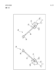
- FIG. 4 is a comparative explanatory diagram of the snow removal tool according to the first embodiment and a conventional example
- FIG. 2 is an explanatory diagram emphasizing the asymmetry of the bucket 110 of FIG. 1
- FIG. 4 is an explanatory diagram showing a usage state of buckets according to the first embodiment; It is a figure which shows the example of mounting of the bucket which concerns on 1st Embodiment.
- FIG. 5 is a view showing variations of the snow remover equipped with the bucket according to the first embodiment; It is a figure which shows the example which mounted the bucket which concerns on 1st Embodiment on the shovel.
- FIG. 11 is an explanatory diagram showing a usage state (bulldozer) of the bucket according to the second embodiment;
- FIG. 10 is a diagram showing an example in which the present invention is mounted on a blade.
- a first embodiment is an embodiment in which the present invention is applied to a bucket of a snow remover.
- the object to be removed is snow.
- the term "removal" includes not only the removal of objects for the purpose of disposal, but also the removal from existing locations for the purpose of moving and accumulating objects.
- FIG. 1 is a comparative explanatory diagram of the snow removal tool 1 according to the first embodiment and a conventional example.
- a snow removal tool 1 includes a bucket 10, a support rod 20, and a grip 30.
- the support rod 20 is a rod-shaped member with one end fixed to the back surface of the bucket 10 .
- the grip 30 is provided at the other end of the support rod 20 (the end opposite to the bucket 10).
- the bucket 10 includes a loading surface 11, a left side 12L, and a right side 12R.
- the loading surface 11 functions as a support surface for an object on which snow, which is an object to be removed, is loaded.
- the loading surface 11 is formed into a curved surface including a bottom surface 11a and a rear surface 11b rising from the rear of the bottom surface 11a.
- the left side 12L is erected from the left side of the loading surface 11.
- the right side surface 12R is erected from the right side of the loading surface 11.
- the height of the right side 12R is formed higher than the height of the left side 12L.
- the left side 12L and the right side 12R are configured as planar or non-planar plate-like bodies in consideration of the strength according to the object.
- the rear surface 11b of the loading surface 11 is formed such that the depth on the right side is deeper than the depth on the left side. That is, the loading surface 11 is formed of a non-flat plate-like body (non-flat) that is left-right asymmetric.
- FIG. 1A is an explanatory diagram emphasizing the asymmetry of bucket 110 in FIG.
- the left side 12L and left depth may be formed deep like the bucket 10 provided in the snow remover 1 shown in FIG. may be formed.
- the conventional bucket 110 has a loading surface 111, a left side 112L, and a right side 112R.
- the shape of the loading surface 111 is symmetrical, and the height of the left side 112L and the right side 112R are the same. Therefore, the accommodation space within the bucket 110 is bilaterally symmetrical.
- FIG. 2 is an explanatory diagram showing the state of use of the bucket 10 according to the first embodiment.
- the snow is stored on the loading surface 11 .
- the snow remover 1 having the bucket 10 according to the first embodiment can remove snow more efficiently than the snow remover 101 having the bucket 110 according to the conventional example.
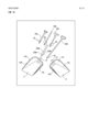
- FIG. 3 is a diagram showing an example in which the bucket according to the first embodiment is mounted on a snow remover.
- the snow removing tools 2a and 2b shown in FIG. 3 differ in the shape of the buckets 10a and 10b.
- the configuration of the arm 40 is common. First, the snow remover 2a will be described.
- the arm 40 of the snow removing tool 2a is formed in a substantially U-shape. One end of the arm 40 is joined to the upper right end of the bucket 10 a and the other end is joined to the upper left end of the bucket 10 . As a modification, the left and right sides may not be joined to the upper end portion, but may be joined to the left and right side surfaces or the rear surface of the loading surface 11 .
- the arm 40 is joined at two points on the left and right sides of the bucket 10a.
- the bucket 10a can be pushed out from two points on the left and right even if the left and right balance of the load acting on the bucket 10a from the contents becomes uneven due to the left and right asymmetry in the inside of the bucket 10a. , making it easier to move the snow remover 2 forward.
- the height from the ground of the junction between the left open end of the arm 40 and the bucket 10a and the height from the ground of the junction between the right open end of the arm 30 and the bucket 10a are formed to be equal.
- a stable thrust force can be transmitted more easily, and the work when the bucket 10a rolls over, rolls forward, or reverses in order to maintain horizontality with the ground and remove snow. You can expect an improvement in performance.
- the rear surface 11b of the bucket 10a is formed in a left-right asymmetrical curved shape such that the height of the right side of the rear surface 11b is higher than the height of the left side of the rear surface 11b.
- the height of the right side surface 12R is higher than the height of the left side surface 12L, and is formed continuously with the rightmost end of the rear surface 11b.
- the height of the left side surface 12L is formed continuously with the leftmost end of the rear surface 11b.
- the bucket 10b of the snow remover 2b has a left side 12L higher than a right side 12R, and a rear surface 11b of the bucket 10b is formed in a laterally asymmetrical curved shape so that the height of the left side of the rear side 11b is higher than the height of the right side of the rear side 11b. It differs from the bucket 10a in that Otherwise, the bucket 10a and the bucket 10b have the same configuration.
- the right side can be raised, and the left side can be raised.
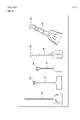
- FIG. 4 is a diagram showing variations of the snow removal tool mounted with the bucket according to the first embodiment.
- the bucket 10c is a bucket in which the loading surface 11, the right side surface 12R, and the left side surface 12L are each formed substantially flat, and the right side surface 12R is higher than the left side surface 12L.
- the bucket 10d has a loading surface 11 having the same shape as the bucket 10c, and the left side 12L is higher than the right side 12R. That is, the shape is such that the right and left sides of the bucket 10c are reversed.
- the bucket 10e is formed in a substantially trapezoidal shape in which the height of the right side of the rear surface 11b is higher than the height of the left side of the rear surface 11b.
- the height of the right side surface 12R is higher than the height of the left side surface 12L, and is formed continuously with the rightmost end of the rear surface 11b.
- the left side surface 12L is formed continuously with the leftmost end of the rear surface 11b.
- the bucket 10f is formed in a substantially trapezoidal shape in which the height of the left side of the rear surface 11b is higher than the height of the right side of the rear surface 11b, and the left side 12L is higher than the right side 12R. That is, the shape is such that the right and left sides of the bucket 10e are reversed.
- the bucket 10g has a curved loading surface 11, a curved right side surface 12R, and a curved left side surface 12L, and the right side surface 12R is higher than the left side surface 12L.
- the bucket 10h has the same shape of the loading surface 11 as the bucket 10g, and the curved left side 12L is higher than the curved right side 12R. That is, the shape is such that the right and left sides of the bucket 10g are reversed.
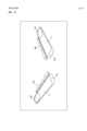
- FIG. 5 is a diagram showing an example in which the bucket according to the first embodiment is mounted on a shovel.
- a shovel 4a in FIG. 5 includes a bucket 10i, a support rod 20, and a grip 30.
- the loading surface 11 of the bucket 10i has a bottom surface 11a and a rear surface 11b that rises smoothly from the bottom surface 11a.
- the bucket 10i has a right side surface 12R that rises smoothly from the bottom surface 11a.
- the height of the right side surface 12R is higher than the left end portion 12EL of the loading surface 11, and is formed continuously with the rightmost end of the rear surface 11b.
- the left end 12EL of the loading surface 11 is not provided with the left side 12L.
- the right side surface 12R is provided on the right side of the loading surface 11, but the left side surface is not provided on the left end portion 12EL, and the bucket 10i is formed left-right asymmetrically.
- the bucket 10j has a left side surface 12L that rises smoothly from the bottom surface 11a.
- the height of the left side surface 12L is higher than the right end portion 12ER of the loading surface 11, and is formed continuously with the leftmost end of the rear surface 11b. That is, the bucket 10j has a shape in which the right and left sides of the bucket 10i are reversed.
- FIG. 6 is a diagram showing variations in the shape of the support rods, arms, and grips that are connected to the bucket according to the first embodiment.
- the shape of the grip may be a straight type with no grip (only the support rod 20), or a grip 30a with a hollow portion.
- a rod-shaped grip 30b connected to the support rod 20 in a substantially T-shape may also be used.
- the curved portion of the U-shaped arm 40 may be used as the grip 30c.
- the bucket 10 includes a loading surface 11 on which objects to be removed are loaded, a left side 12L erected from the left side of the loading surface 11, and a left side 12L erected from the right side of the loading surface 11.
- the object storage space 13 formed by the loading surface 11, the left side 12L, and the right side 12R is asymmetrically formed.
- FIG. 7 shows an example in which the support rod 20 is detachably attached to the bucket 10g.
- the bucket 10g will be described as an example in FIG. 7, it is not limited to the bucket 10g.
- the back surface of the loading surface 11 of the bucket 10g is provided with support rod holding portions 15, 15a for holding the ends of the support rods 20.
- the support rod holding part 15 is formed in a cylindrical shape, one end is fixed to the back surface of the loading surface 11, and the other end is open.
- the end 21 of the support rod 20 is inserted into the support rod holder 15 when used.
- a removal tool such as a snow remover, a shovel, or a scoop includes a bucket and a support rod, and the support rod is detachably connected to the rear surface of the rear surface of the bucket (opposite side of the storage space). be done.
- the bucket 10g and the support rod 20 can be stored separately, making them easier to store.
- the snow removal tool is not used in the summer, so it will be easier to store and usability will be improved.
- FIG. 8 is a diagram showing another example in which the support rod 20 is detachably attached to the bucket.
- the bucket 10k with the higher right side surface 12R and the bucket 10l with the higher left side surface 12L each include a support rod holding portion 15.
- the support rod 20 includes a middle rod (shaft) 20M and a hand rod 20a connected to the middle rod 20M.
- the hand rod 20a has the grip 30a shown in FIG. 6, but it may be a hand rod 20b without a grip or a hand rod 20c with a T-shaped grip 30c.
- a flip (leaf spring) 22 is provided on the side opposite to the grip 30a of the hand rod 20a.
- a through groove (not shown) is formed on the connection side of the middle rod 20M with the hand rod 20a, through which the flick 22 protrudes when the hand rod 20a is connected.
- a flip (leaf spring) 22M is provided on the connection side of the middle rod 20M with the support rod holding portion 15.
- a through groove (not shown) is formed on the connection side of the support rod holding portion 15 with the middle rod 20M, through which the flick 22M protrudes when the middle rod 20M is connected.
- a snow remover is formed by connecting the middle rod 20M to the bucket 10k and further connecting any one of the hand rods 20a, 20b, and 20c.
- the support rod may be a support rod 20d in which the grip 30a is formed on a single rod-shaped member without providing the middle rod 20M.
- a repelling 22 is also formed on the supporting rod 20d.
- the left-right asymmetry of the storage space can be reversed.
- the situation of the work place such as when you want to stack the objects on the left side of the moving direction of the snow removal tool (for example, when the snow melting groove is on the left side of the moving direction), when you want to stack on the right side (when the snow melting groove is on the right side of the moving direction), etc.
- the object overflows from the lower side of the height of the left side 12L and the height of the right side 12R, and the object overflows from the higher side. Therefore, only one side of the trajectory of the bucket 10 needs to be removed again, improving workability. Since the object overflows, the removal work of the object can be performed only on one side of the trajectory of the bucket 10, and the removal work can be performed efficiently.
- a second embodiment is an embodiment in which a bucket according to the present invention is mounted on a bucket of a working machine.
- FIG. 9 is an explanatory diagram showing the state of use of the bucket (wheel loader) according to the second embodiment.
- the wheel loader 50 includes a body 51 and a front work machine 55.
- the fuselage 51 has tires 52 and a cab 53 .
- the tire 52 corresponds to a traveling body that allows the wheel loader 50 to travel.
- a driver's seat for the operator of the wheel loader 50 or a remote-controlled receiving control device is installed inside the cab 53.
- the cab 53 is provided above the tire 52 .
- the front work machine 55 is connected to the front of the machine body 51 so that it can be raised.
- the front working machine 55 includes a left arm 54L, a right arm 54R, and a bucket 10m.
- a bucket 10m is connected to the front end of the left arm 54L and the front end of the right arm so that it can be raised.
- the bucket 10m may be an attachment (detachable member) detachably formed at the front end of the left arm 54L and the front end of the right arm 54R. It may be possible to connect and fix.
- the bucket 10m includes a loading surface 11, a left side 12L, and a right side 12R.
- the length in the depth direction of the bottom surface 11a of the loading surface 11 is shorter than the length in the height direction of the rear surface 11b.
- the area of the right side surface 12R is formed wider than the area of the left side surface 12L.
- the bucket 10m has an object storage space that is left-right asymmetric. , overflow from the left of the bucket 10m. As a result, even if objects overflowing on the left side of the travel locus of the wheel loader 50 accumulate, they do not accumulate on the right side. Improve efficiency.
- a bucket 10n may be provided in the front work machine 55 instead of the bucket 10m.
- the bucket 10n is formed such that the area of the left side 12L is larger than the area of the right side 12L. Other configurations are the same as the bucket 10m.
- FIG. 10 is an explanatory diagram showing the state of use of the bucket (bulldozer) according to the second embodiment.
- the bulldozer 60 includes a body 61 and a front work machine 65.
- the fuselage 61 includes a crawler 62 and a cab 63.
- the crawler 62 corresponds to a traveling body that allows the bulldozer 60 to travel.
- a bucket 10o is provided at the front end of the front work machine 65.
- the bucket 10o is formed of a left-right asymmetric non-flat plate-like body (non-flat), with the area of the right side 12R being larger than the area of the left side 12L.
- a bucket 10p may be provided on the front working machine 61 instead of the bucket 10o.
- the bucket 10p is formed such that the area of the left side 12L is larger than the area of the right side 12L. Other configurations are the same as the bucket 10o.
- a bucket 10 according to the second embodiment is attached to the front of a working machine such as a wheel loader 50 or a bulldozer 60.
- the work machine includes a machine body and a front working machine, the machine machine has a traveling body and a cab mounted above the traveling body, and the front working machine has at least one or more.
- An arm and a bucket wherein the rear end of the arm is connected to the fuselage so that it can be raised, the bucket is connected to the front end of the arm so that it can be raised, and the bucket is an object to be removed. is loaded, a left side standing from the left side of the loading side, and a right side standing from the right side of the loading side, wherein the loading side, the left side, and the right side
- the storage space for the object to be formed is characterized in that it is formed left-right asymmetrically.
- the work machine includes a pair of left and right arms, and the bucket is connected to the front ends of the arms so that it can be raised and lowered.
- FIG. 11 is a diagram showing an example in which the present invention is mounted on a blade.
- the blades 70 a and 70 b in FIG. 11 are attachment-type blades used in the front working machine 65 of the bulldozer 60 .
- the unloading plate 70a has a curved loading surface 11, a right side 12R, and a left side 12L.
- the unloading plate 70a is formed of a left-right asymmetric non-flat plate-like body (non-flat) with the area of the right side 12R larger than the area of the left side 12L.
- the unloading plate 70b is formed of a left-right asymmetrical non-flat plate-like body (non-flat) with the area of the left side 12L larger than the area of the right side 12R.
- the earth removing plates 70a and 70b can be appropriately selected and installed as the front work machine 65, improving usability.
- the object overflows from only one side of the traveling locus of the working machine, so that the removal operation can be performed again on only one side, and the working efficiency can be improved.
- the bucket of the present invention can be changed in various ways without changing the gist of the present invention.
- the height of the left side 12L may be higher than the right side 12R, and the area of the left side 12L may be larger than the area of the right side 12R.
- the present invention may be applied to scoops and shovel buckets.
- the object to be removed is not limited to snow, but may be earth and sand, fertilizer, feed, cement, grains, shells, and fallen leaves.
- the above embodiment is merely one of the best modes at present.
- the material of the bucket 10 may be metal or resin.
- the work machine may be a hydraulic excavator.
- a hydraulic excavator includes a body, a boom connected to the body so that it can be raised, an arm rotatably connected to the front end of the boom, and an attachment (detachably formed) bucket to the front end of the arm. and the present invention may be applied to the bucket.
Landscapes
- Engineering & Computer Science (AREA)
- Civil Engineering (AREA)
- Structural Engineering (AREA)
- Mining & Mineral Resources (AREA)
- General Engineering & Computer Science (AREA)
- Mechanical Engineering (AREA)
- Architecture (AREA)
- Shovels (AREA)
Priority Applications (2)
| Application Number | Priority Date | Filing Date | Title |
|---|---|---|---|
| JP2022549428A JPWO2023017610A1 (https=) | 2021-08-13 | 2021-08-13 | |
| PCT/JP2021/029783 WO2023017610A1 (ja) | 2021-08-13 | 2021-08-13 | バケット |
Applications Claiming Priority (1)
| Application Number | Priority Date | Filing Date | Title |
|---|---|---|---|
| PCT/JP2021/029783 WO2023017610A1 (ja) | 2021-08-13 | 2021-08-13 | バケット |
Publications (1)
| Publication Number | Publication Date |
|---|---|
| WO2023017610A1 true WO2023017610A1 (ja) | 2023-02-16 |
Family
ID=85200064
Family Applications (1)
| Application Number | Title | Priority Date | Filing Date |
|---|---|---|---|
| PCT/JP2021/029783 Ceased WO2023017610A1 (ja) | 2021-08-13 | 2021-08-13 | バケット |
Country Status (2)
| Country | Link |
|---|---|
| JP (1) | JPWO2023017610A1 (https=) |
| WO (1) | WO2023017610A1 (https=) |
Citations (8)
| Publication number | Priority date | Publication date | Assignee | Title |
|---|---|---|---|---|
| JPS61169124U (https=) * | 1985-04-02 | 1986-10-20 | ||
| JPS6260614U (https=) * | 1985-09-30 | 1987-04-15 | ||
| JPS62233346A (ja) * | 1986-04-02 | 1987-10-13 | Toru Igarashi | プラウ装置およびそれを装着した土砂掘鑿、採取用バケツト |
| JPS62169014U (https=) * | 1986-04-10 | 1987-10-27 | ||
| JPS62181618U (https=) * | 1986-05-09 | 1987-11-18 | ||
| JPH0184319U (https=) * | 1987-11-27 | 1989-06-05 | ||
| JP2006046034A (ja) * | 2004-07-30 | 2006-02-16 | Shizuo Kikura | スノーダンプ |
| US20150373895A1 (en) * | 2013-02-27 | 2015-12-31 | Robert Bartnik | Configurable Hand Tool System With Interchangeable Work Heads |
Family Cites Families (4)
| Publication number | Priority date | Publication date | Assignee | Title |
|---|---|---|---|---|
| JPS6184717U (https=) * | 1984-11-09 | 1986-06-04 | ||
| JP2510507Y2 (ja) * | 1989-06-09 | 1996-09-11 | 油谷重工株式会社 | バケット |
| JPH07166521A (ja) * | 1993-12-13 | 1995-06-27 | Hitachi Constr Mach Co Ltd | 路面切削装置 |
| CH709958B1 (it) * | 2014-08-04 | 2018-07-13 | Al Adawi Walid | Pala da neve con elemento ribaltabile. |
-
2021
- 2021-08-13 JP JP2022549428A patent/JPWO2023017610A1/ja active Pending
- 2021-08-13 WO PCT/JP2021/029783 patent/WO2023017610A1/ja not_active Ceased
Patent Citations (8)
| Publication number | Priority date | Publication date | Assignee | Title |
|---|---|---|---|---|
| JPS61169124U (https=) * | 1985-04-02 | 1986-10-20 | ||
| JPS6260614U (https=) * | 1985-09-30 | 1987-04-15 | ||
| JPS62233346A (ja) * | 1986-04-02 | 1987-10-13 | Toru Igarashi | プラウ装置およびそれを装着した土砂掘鑿、採取用バケツト |
| JPS62169014U (https=) * | 1986-04-10 | 1987-10-27 | ||
| JPS62181618U (https=) * | 1986-05-09 | 1987-11-18 | ||
| JPH0184319U (https=) * | 1987-11-27 | 1989-06-05 | ||
| JP2006046034A (ja) * | 2004-07-30 | 2006-02-16 | Shizuo Kikura | スノーダンプ |
| US20150373895A1 (en) * | 2013-02-27 | 2015-12-31 | Robert Bartnik | Configurable Hand Tool System With Interchangeable Work Heads |
Also Published As
| Publication number | Publication date |
|---|---|
| JPWO2023017610A1 (https=) | 2023-02-16 |
Similar Documents
| Publication | Publication Date | Title |
|---|---|---|
| CN104487636A (zh) | 用于挖掘铲斗的唇部 | |
| CA2080655A1 (en) | Blades for snow-removal vehicles and vehicles therewith | |
| US7690441B2 (en) | Blade device for working machine and working machine mounting blade device | |
| CN101311430A (zh) | 工作机 | |
| US5156215A (en) | Counterweight assembly for crawler tractor | |
| JPS58113430A (ja) | 土工機械用ブレ−ド | |
| JPWO2015167025A1 (ja) | バケットおよびこれを備えた作業車両 | |
| US20070180742A1 (en) | Tool mount for a self-propelled vehicle | |
| CN101311429A (zh) | 操作工作机的方法 | |
| WO2023017610A1 (ja) | バケット | |
| CN1782239B (zh) | 用于施工机械的刮板装置和具有刮板装置的施工机械 | |
| CN210562361U (zh) | 一种推土机构及铲土运输机械 | |
| CN215594176U (zh) | 一种履带式推土机 | |
| CN101258290B (zh) | 用于工程机械的铲刀装置及搭载有该装置的工程机械 | |
| CN215165944U (zh) | 一种建筑推土机实现即时堆放的推板 | |
| CN212534265U (zh) | 一种用于公路超载预压施工的挖沟装置 | |
| JP2004183475A (ja) | 自律運転用オーバーショットローダー | |
| CN215165921U (zh) | 一种工程机械装置及多用途工程车 | |
| CN107806125B (zh) | 一种铲刀组件及推土机 | |
| JP6869154B2 (ja) | 歩行型ブレード作業機 | |
| JP2007077690A (ja) | 作業機械用ブレード装置と同ブレード装置が搭載された建設・土木車両 | |
| JP7853706B2 (ja) | 工具収納ラック | |
| JP2017115443A (ja) | 歩行型ブレード作業機 | |
| CN216339749U (zh) | 一种多功能的工程挖掘机 | |
| JP4214125B2 (ja) | スタビライザ |
Legal Events
| Date | Code | Title | Description |
|---|---|---|---|
| ENP | Entry into the national phase |
Ref document number: 2022549428 Country of ref document: JP Kind code of ref document: A |
|
| 121 | Ep: the epo has been informed by wipo that ep was designated in this application |
Ref document number: 21953505 Country of ref document: EP Kind code of ref document: A1 |
|
| NENP | Non-entry into the national phase |
Ref country code: DE |
|
| 122 | Ep: pct application non-entry in european phase |
Ref document number: 21953505 Country of ref document: EP Kind code of ref document: A1 |