WO2023013739A1 - ロボット制御装置、ロボット制御システム、及びロボット制御方法 - Google Patents
ロボット制御装置、ロボット制御システム、及びロボット制御方法 Download PDFInfo
- Publication number
- WO2023013739A1 WO2023013739A1 PCT/JP2022/030010 JP2022030010W WO2023013739A1 WO 2023013739 A1 WO2023013739 A1 WO 2023013739A1 JP 2022030010 W JP2022030010 W JP 2022030010W WO 2023013739 A1 WO2023013739 A1 WO 2023013739A1
- Authority
- WO
- WIPO (PCT)
- Prior art keywords
- robot
- calibration
- control unit
- orientation
- range
- Prior art date
- Legal status (The legal status is an assumption and is not a legal conclusion. Google has not performed a legal analysis and makes no representation as to the accuracy of the status listed.)
- Ceased
Links
Images



Classifications
-
- B—PERFORMING OPERATIONS; TRANSPORTING
- B25—HAND TOOLS; PORTABLE POWER-DRIVEN TOOLS; MANIPULATORS
- B25J—MANIPULATORS; CHAMBERS PROVIDED WITH MANIPULATION DEVICES
- B25J9/00—Program-controlled manipulators
- B25J9/16—Program controls
- B25J9/1679—Program controls characterised by the tasks executed
- B25J9/1692—Calibration of manipulator
-
- B—PERFORMING OPERATIONS; TRANSPORTING
- B25—HAND TOOLS; PORTABLE POWER-DRIVEN TOOLS; MANIPULATORS
- B25J—MANIPULATORS; CHAMBERS PROVIDED WITH MANIPULATION DEVICES
- B25J13/00—Controls for manipulators
- B25J13/08—Controls for manipulators by means of sensing devices, e.g. viewing or touching devices
-
- B—PERFORMING OPERATIONS; TRANSPORTING
- B25—HAND TOOLS; PORTABLE POWER-DRIVEN TOOLS; MANIPULATORS
- B25J—MANIPULATORS; CHAMBERS PROVIDED WITH MANIPULATION DEVICES
- B25J19/00—Accessories fitted to manipulators, e.g. for monitoring, for viewing; Safety devices combined with or specially adapted for use in connection with manipulators
- B25J19/02—Sensing devices
- B25J19/04—Viewing devices
-
- B—PERFORMING OPERATIONS; TRANSPORTING
- B25—HAND TOOLS; PORTABLE POWER-DRIVEN TOOLS; MANIPULATORS
- B25J—MANIPULATORS; CHAMBERS PROVIDED WITH MANIPULATION DEVICES
- B25J9/00—Program-controlled manipulators
- B25J9/10—Program-controlled manipulators characterised by positioning means for manipulator elements
-
- B—PERFORMING OPERATIONS; TRANSPORTING
- B25—HAND TOOLS; PORTABLE POWER-DRIVEN TOOLS; MANIPULATORS
- B25J—MANIPULATORS; CHAMBERS PROVIDED WITH MANIPULATION DEVICES
- B25J9/00—Program-controlled manipulators
- B25J9/16—Program controls
- B25J9/1694—Program controls characterised by use of sensors other than normal servo-feedback from position, speed or acceleration sensors, perception control, multi-sensor controlled systems, sensor fusion
- B25J9/1697—Vision controlled systems
-
- G—PHYSICS
- G05—CONTROLLING; REGULATING
- G05B—CONTROL OR REGULATING SYSTEMS IN GENERAL; FUNCTIONAL ELEMENTS OF SUCH SYSTEMS; MONITORING OR TESTING ARRANGEMENTS FOR SUCH SYSTEMS OR ELEMENTS
- G05B2219/00—Program-control systems
- G05B2219/30—Nc systems
- G05B2219/39—Robotics, robotics to robotics hand
- G05B2219/39008—Fixed camera detects reference pattern held by end effector
Definitions
- the present disclosure relates to a robot control device, a robot control system, and a robot control method.
- a robot control device includes a control unit that controls a robot.
- the control unit performs a first calibration of the robot at at least one first calibration position included in a first calibration range set in an action space of the robot.
- the controller performs a second calibration of the robot at at least one second calibration position.
- the at least one second calibration position is included in a second calibration range that is a partial range of the first calibration range, and is set at a higher density than the at least one first calibration position. be done.
- a robot control system includes the robot control device and the robot.
- a control unit that controls a robot controls the robot at at least one first calibration position included in a first calibration range set in an operation space of the robot. performing a first calibration of.
- the control unit is included in a second calibration range that is a partial range of the first calibration range, and is set at a higher density than the at least one first calibration position. performing a second calibration of the robot at the selected at least one second calibration position.
- FIG. 1 is a block diagram showing a configuration example of a robot control system according to an embodiment
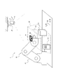
- FIG. 1 is a schematic diagram showing a configuration example of a robot control system according to an embodiment
- FIG. 4 is a schematic diagram showing an example of a calibration range
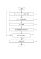
- 4 is a flowchart showing a procedure example of executing a first calibration as a robot control method according to one embodiment
- 6 is a flowchart showing a procedure example of executing a second calibration as a robot control method according to one embodiment
- a robot control system 1 includes a robot 40 , a robot control device 10 and a spatial information acquisition section 20 .
- the robot 40 operates in a predetermined motion space.
- the space information acquisition unit 20 generates depth information of the motion space in which the robot 40 moves.
- the spatial information acquisition unit 20 calculates the distance to the measurement point located on the surface of the object 50 existing in the motion space.
- the distance from the spatial information acquisition unit 20 to the measurement point is also called depth.
- Depth information is information about the depth measured for each measurement point. In other words, the depth information is information about the distance to the measurement point located on the surface of the object 50 existing in the motion space.
- the depth information may be expressed as a depth map that associates the direction viewed from the spatial information acquisition unit 20 and the depth in that direction.
- the spatial information acquisition unit 20 generates depth information of the motion space based on the (X, Y, Z) coordinate system.
- the robot control device 10 operates the robot 40 based on the depth information generated by the space information acquisition section 20 .
- the robot controller 10 operates the robot 40 based on the (X_RB, Y_RB, Z_RB) coordinate system.
- the (X_RB, Y_RB, Z_RB) coordinate system is also called the coordinate system of the robot 40 .
- the (X, Y, Z) coordinate system is also called the coordinate system of the spatial information acquisition unit 20 .
- the coordinate system of the robot 40 may be set as the same coordinate system as the coordinate system of the spatial information acquisition unit 20, or may be set as a different coordinate system.
- the robot control device 10 converts the depth information generated in the coordinate system of the space information acquisition unit 20 into the coordinates of the robot 40. It is converted into a system and used.
- the number of robots 40 and robot control devices 10 is not limited to one as illustrated, but may be two or more. As illustrated, the number of spatial information acquisition units 20 may be one for one motion space, or may be two or more. Each component will be specifically described below.
- the robot control device 10 includes a control section 11 and a storage section 12 .
- the control unit 11 may include at least one processor to implement various functions of the robot control device 10 .
- the processor may execute programs that implement various functions of the robot controller 10 .
- a processor may be implemented as a single integrated circuit.
- An integrated circuit is also called an IC (Integrated Circuit).
- a processor may be implemented as a plurality of communicatively coupled integrated and discrete circuits.
- the processor may be configured including a CPU (Central Processing Unit).
- the processor may be configured including a DSP (Digital Signal Processor) or a GPU (Graphics Processing Unit). Processors may be implemented based on various other known technologies.
- the storage unit 12 may be configured including an electromagnetic storage medium such as a magnetic disk, or may be configured including a memory such as a semiconductor memory or a magnetic memory.
- the storage unit 12 may be configured as an HDD (Hard Disk Drive) or an SSD (Solid State Drive).
- the storage unit 12 stores various information, programs executed by the control unit 11, and the like.
- the storage unit 12 may function as a work memory for the control unit 11 .
- the control unit 11 may include at least part of the storage unit 12 .
- the robot control device 10 may further include a communication device configured to be able to communicate with the spatial information acquisition unit 20 and the robot 40 by wire or wirelessly.
- a communication device may be configured to be able to communicate with communication schemes based on various communication standards.
- a communication device may be configured according to known communication technologies. A detailed description of the hardware of the communication device and the like is omitted.
- the functions of the communication device may be realized by one interface, or may be realized by separate interfaces for each connection destination.
- the control unit 11 may be configured to communicate with the spatial information acquisition unit 20 and the robot 40 .
- the control unit 11 may be configured including a communication device.
- the robot 40 includes an arm 42, an end effector 44 attached to the arm 42, and a mark 46 installed on the end effector 44, as illustrated in FIG. Note that the mark 46 may be placed on the arm 42 instead of the end effector 44 .
- the arm 42 may be configured as, for example, a 6-axis or 7-axis vertical articulated robot.
- the arm 42 may be configured as a 3-axis or 4-axis horizontal articulated robot or SCARA robot.
- Arm 42 may be configured as a 2-axis or 3-axis Cartesian robot.
- Arm 42 may be configured as a parallel link robot or the like.
- the number of axes forming the arm 42 is not limited to the illustrated one.
- the end effector 44 may include, for example, a gripping hand configured to grip a work object.
- the grasping hand may have multiple fingers. The number of fingers of the grasping hand may be two or more. The fingers of the grasping hand may have one or more joints.
- the end effector 44 may include a suction hand configured to be able to suction a work target.
- the end effector 44 may include a scooping hand configured to scoop the work object.
- the end effector 44 may include a tool such as a drill, and may be configured to perform various machining operations such as drilling holes in a work object.
- the end effector 44 is not limited to these examples, and may be configured to perform various other operations.
- the robot 40 can control the position of the end effector 44 by operating the arm 42 .
- the end effector 44 may have an axis that serves as a reference for the direction in which it acts on the work object. If the end effector 44 has an axis, the robot 40 can control the orientation of the end effector 44 axis by moving the arm 42 .
- the robot 40 controls the start and end of the motion of the end effector 44 acting on the work piece.
- the robot 40 can move or process a work object by controlling the position of the end effector 44 or the direction of the axis of the end effector 44 and controlling the motion of the end effector 44 .
- the robot 40 may further include sensors that detect the state of each component of the robot 40 .
- the sensors may detect information regarding the actual position or orientation of each component of the robot 40 or the velocity or acceleration of each component of the robot 40 .
- the sensors may detect forces acting on each component of the robot 40 .
- the sensors may detect the current flowing through the motors that drive each component of the robot 40 or the torque of the motors.
- the sensors can detect information resulting from the actual movement of robot 40 .
- the robot control device 10 can grasp the actual operation result of the robot 40 by acquiring the detection result of the sensor. That is, the robot control device 10 can acquire the state of the robot 40 based on the detection result of the sensor.
- the robot control device 10 recognizes the position of the mark 46 or the position of the end effector 44 on which the mark 46 is installed based on the image of the mark 46 captured by the spatial information acquisition unit 20 . Further, the robot control device 10 recognizes the state of the robot 40 based on the image of the mark 46 captured by the space information acquisition section 20 . The robot control device 10 performs calibration of the robot 40 by comparing the state of the robot 40 obtained based on the detection result of the sensor and the state of the robot 40 obtained based on the image of the mark 46 . can.
- the spatial information acquisition unit 20 acquires spatial information regarding the motion space of the robot 40 .
- the spatial information acquisition unit 20 may photograph the motion space and acquire an image of the motion space as the spatial information.
- the spatial information acquisition unit 20 may photograph an object 50 existing in the motion space, as illustrated in FIG. 2 .
- the spatial information acquisition section 20 may be configured as a camera.
- the 3D stereo camera photographs an object 50 existing in the motion space, calculates the distance to a measurement point located on the surface of the object 50 existing in the motion space as depth, and generates depth information.
- the spatial information acquisition section 20 may be configured as a 3D stereo camera.
- the spatial information acquisition unit 20 may be configured as a LiDAR (light detection and ranging).
- the spatial information acquisition unit 20 may acquire depth information of the motion space as the spatial information.
- the spatial information acquisition unit 20 is not limited to these devices and may be configured as various devices.
- the spatial information acquisition unit 20 may acquire various types of information as the spatial information, without being limited to the image or depth information of the motion space.
- the spatial information acquisition section 20 may include an imaging device.
- the spatial information acquisition section 20 may further include an optical system.
- the space information acquisition unit 20 may output the captured image of the motion space to the robot control device 10 .
- the space information acquisition unit 20 may generate depth information in the motion space of the robot 40 and output it to the robot control device 10 .
- the space information acquisition unit 20 may generate point group information in the motion space of the robot 40 and output it to the robot control device 10 . That is, the spatial information acquisition unit 20 may output the spatial information in the form of point cloud data.
- the point cloud information may have spatial information.
- the point group information is information on a set of measurement points located on the surface of the object 50 existing in the motion space, and is information including coordinate information or color information on each measurement point.
- the point group information can also be said to be data representing the object 50 in the measurement space with a plurality of points. Since the spatial information is in the form of point cloud data, the data density can be made smaller than the spatial information based on the initial data acquired by the spatial information acquiring section 20 .
- the spatial information acquisition unit 20 has an FOV (Field Of View).
- the FOV corresponds to the imaging range of the spatial information acquisition unit 20.
- the spatial information acquisition unit 20 can photograph the range included in the FOV.
- the actual field of view size of the spatial information acquisition section 20 is determined based on the FOV of the spatial information acquisition section 20 and the depth information.
- the robot control device 10 can acquire the position and posture of the mark 46 of the robot 40 based on the actual field of view size of the spatial information acquiring unit 20 and the image including the mark 46 of the robot 40 captured by the spatial information acquiring unit 20. .
- the robot control device 10 can calculate the position and orientation of the mark 46 based on the image by analyzing the image of the mark 46 using a predetermined algorithm.
- a predetermined algorithm may include, for example, a mathematical formula or a table, or may include a program specifying arithmetic processing.
- the predetermined algorithm may include parameters for correcting the image-based calculation results.
- the robot control device 10 operates the robot 40 to act on a work target such as an object 50 existing in the action space, or operates the robot 40 to avoid the object 50 .
- the robot control device 10 operates the robot 40 so as to act on the object 50 or avoid the object 50 based on the photographed image of the object 50 captured by the spatial information acquisition unit 20 .
- the control unit 11 of the robot control device 10 can acquire the state of the robot 40 based on the position and orientation of the mark 46 captured in the image captured by the space information acquisition unit 20, and can acquire the positional relationship between the robot 40 and the object 50. .
- the control unit 11 acquires the state of the robot 40 based on a sensor of the robot 40 such as an encoder installed on the arm 42 or the like.
- the state based on the sensor of the robot 40 expresses the position and orientation of the robot 40 with higher accuracy than the state based on the captured image of the spatial information acquisition unit 20 .
- the control unit 11 can control the robot 40 in the motion space with high accuracy by matching the state of the robot 40 based on the captured image of the space information acquisition unit 20 with the state of the robot 40 based on the sensor of the robot 40.
- the work of matching the state of the robot 40 based on the captured image of the spatial information acquisition unit 20 with the state of the robot 40 based on the sensor of the robot 40 is also called calibration.
- the control unit 11 performs calibration so that the (X, Y, Z) coordinate system of the spatial information acquisition unit 20 matches the (X_RB, Y_RB, Z_RB) coordinate system of the robot 40 .
- the control unit 11 estimates the relative positional relationship between the coordinate system of the spatial information acquiring unit 20 and the coordinate system of the robot 40, and converts the coordinate system of the spatial information acquiring unit 20 to the coordinate system of the robot 40 based on the estimated relative positional relationship. Good to match.
- the control unit 11 may perform calibration using at least part of the FOV of the spatial information acquisition unit 20 as a calibration range.
- the control unit 11 performs calibration in a first calibration range 60 and a second calibration range 62 shown in FIGS. 2 and 3.
- FIG. First calibration range 60 includes second calibration range 62 .
- the second calibration range 62 corresponds to a partial range of the first calibration range 60 .
- the first calibration range 60 is shown as a region surrounded by two-dot chain lines in FIGS. 2 and 3.
- FIG. A second calibration range 62 is shown in FIGS. 2 and 3 as the area enclosed by the dashed lines.
- the first calibration range 60 and the second calibration range 62 are simply referred to as calibration ranges when not distinguished.
- the calibration range corresponds to the range in which the robot 40 is calibrated.
- the calibration range may include the work area of robot 40 .
- the calibration range may be the range where the working area of the robot 40 and the FOV overlap.
- control unit 11 sets points for performing calibration within the calibration range.
- the points for performing calibration are also referred to as calibration positions.
- a calibration position set within the first calibration range 60 is also referred to as a first calibration position.
- a calibration position set within the second calibration range 62 is also referred to as a second calibration position. Note that the second calibration position is set at a position different from the first calibration position.
- the control unit 11 moves the mark 46 of the robot 40 to the calibration position and causes the spatial information acquisition unit 20 to photograph the mark 46 .
- the control unit 11 calculates the position and orientation of the mark 46 based on the image of the mark 46 .
- the control unit 11 adjusts the position and orientation of the mark 46 based on the image so that the position and orientation of the mark 46 calculated based on the image match the position and orientation of the mark 46 determined based on the detection result of the sensor of the robot 40 .
- Correct position and posture. Correction of the position and orientation of the mark 46 based on the image corresponds to calibration.
- the position and orientation of mark 46 is also referred to as the tip position and orientation.
- Calibration corresponds to correction of tip position and orientation.
- a calibration position corresponds to a position for correcting the tip position and orientation.
- control unit 11 may perform calibration as described below.
- the control unit 11 generates control information for the robot 40 for moving the mark 46 of the robot 40 to the calibration position.
- the control unit 11 operates the robot 40 based on the control information to move the mark 46 of the robot 40 to the calibration position.
- the control unit 11 acquires an image of the mark 46 from the spatial information acquisition unit 20 .
- the control unit 11 calculates the position and orientation of the mark 46 based on the image.
- the position and orientation of the mark 46 calculated based on the image are also referred to as the tip position and orientation based on the image.
- the control unit 11 calculates the position and orientation of the mark 46 determined based on the detection result of the sensor of the robot 40 .
- the position and orientation of the mark 46 calculated based on the sensor detection results are also referred to as the tip position and orientation based on the sensor.
- the control unit 11 compares the tip position/orientation based on the image and the tip position/orientation based on the sensor.
- the control unit 11 corrects the tip position/orientation based on the image so that the tip position/orientation based on the image matches the tip position/orientation based on the sensor.
- the control unit 11 may correct the algorithm for calculating the tip position/orientation based on the image.
- the control unit 11 may correct the parameters included in the algorithm, or may correct the formula, table, or program. When a plurality of calibration positions are set, the control unit 11 moves the robot 40 to each calibration position, acquires an image of the mark 46 at each calibration position, and determines the tip position/orientation based on the image. to correct.
- the location to be calibrated is not limited to the position and orientation of the mark 46 . That is, the control unit 11 stores in advance the position of the mark 46 and the positional relationship between the calibration target portion, which is a part of the robot 40 to be calibrated, and performs calibration based on the position and orientation of the mark 46 based on the image. Alternatively, the position and orientation of the motion target portion may be calculated. Then, calibration can be performed by comparing the position and orientation of the part to be calibrated based on the detection result of the sensor of the robot 40 . Therefore, it is possible to calibrate other than the position and orientation of the mark 46 . In the above example, the position and orientation of the tip of the robot 40 is the target of calibration. .
- the control unit 11 sets a calibration range in advance before performing calibration. Also, the control unit 11 sets a calibration position included in the calibration range. The controller 11 sets at least one first calibration position within the first calibration range 60 . The controller 11 sets at least one second calibration position within the second calibration range 62 . The control unit 11 sets the calibration positions such that the density of the second calibration positions is higher than the density of the first calibration positions. In other words, the controller 11 sets the second calibration positions at a higher density than the first calibration positions. Conversely, the control unit 11 sets the first calibration positions at a lower density than the second calibration positions. Also, the number of second calibration positions may be greater than or equal to the number of first calibration positions.
- the control unit 11 generates control information for the robot 40 so as to move the robot 40 to the calibration position.
- the control unit 11 generates, as a calibration item, information specifying the tip position and orientation when the robot 40 is moved and the recognition result of the mark 46 of the robot 40 .
- This calibration item is also referred to as the first calibration item.
- a calibration item that does so is also referred to as a second calibration item.
- the calibration item is, for example, information about coordinates.
- the calibration item is, for example, coordinate information indicating the tip position and orientation based on the detection result of the sensor of the robot 40 when the robot 40 is moved to the calibration position, or is recognized by the spatial information acquisition unit 20. coordinate information indicating the position and orientation of the tip based on the recognition result of the mark 46.
- the control unit 11 may generate calibration items as described below.
- the control unit 11 acquires, for example, information on the real field size of the spatial information acquisition unit 20 or information on the FOV from the spatial information acquisition unit 20 .
- the control unit 11 sets the calibration range based on the actual field of view size or FOV of the spatial information acquisition unit 20 and the work area of the robot 40 .
- the controller 11 may set the calibration range based on the position of the object 50 in the motion space of the robot 40 .
- the control unit 11 may set the calibration range based on the depth information or point group information of the object 50 detected by the spatial information acquisition unit 20 .
- the control unit 11 may set the first calibration range 60 based on the actual field of view size and the FOV, for example.
- the control unit 11 may set the second calibration range 62 based on the work area, for example.
- the calibration range may have a plurality of second calibration ranges 62 .
- the control unit 11 may set the second calibration range 62 in each of the place where the object is gripped and the place where the object is placed as the work area. good. 2 and 3, the shape of the first calibration range 60 is set to a truncated quadrangular pyramid shape.
- the shape of the second calibration range 62 is set to a rectangular parallelepiped shape. The shape of the calibration range is not limited to these and may be set to various other shapes.
- the control unit 11 matches the tip position/orientation based on the sensor of the robot 40 with the tip position/orientation based on the image of the spatial information acquisition unit 20 . Specifically, the controller 11 moves the robot 40 to the first position.
- the control unit 11 generates control information for operating the robot 40 so that the mark 46 of the robot 40 assumes a predetermined position and posture, and controls the robot 40 based on the control information to move the robot 40 to the first position. move.
- the first position may be a predetermined position included in the FOV of the spatial information acquisition section 20 .
- the first position may be the center position of the FOV of the spatial information acquisition unit 20, for example.
- the control unit 11 acquires an image of the mark 46 when the robot 40 moves to the first position, and calculates the position and orientation of the mark 46 as the tip position and orientation based on the image. Also, the control unit 11 calculates the tip position and orientation based on the sensor. Based on the comparison between the tip position/orientation based on the image and the tip position/orientation based on the sensor, the control unit 11 adjusts the position of the robot 40 so that the position of the robot 40 becomes the first position based on the detection result of the sensor in the image. Correct the control information. The control unit 11 moves the robot 40 based on the corrected control information so that the position of the robot 40 in the coordinate system of the robot 40 and the position of the robot 40 in the coordinate system of the space information acquisition unit 20 match. Update 40 states. In other words, it can be said that the control unit 11 updates the state of the robot 40 so that the position of the robot 40 becomes the first position in the image.
- the control unit 11 may generate at least one candidate position for the calibration position within the calibration range.
- the at least one candidate calibration position is also referred to as at least one second position.
- the control unit 11 may set the first position as one of the at least one second positions.
- the control unit 11 may set at least one second position to a position different from the first position.
- the control unit 11 selects the first calibration position and the second calibration position from among the first position or at least one second position set in each of the first calibration range 60 and the second calibration range 62 . should be selected.
- the at least one second location may include points located at corners or sides of the calibration area. Alternatively, the at least one second position may comprise a point located inside the calibration range.
- the control unit 11 estimates the state of the robot 40 when the robot 40 moves to the second position by simulating the motion of the robot 40 . That is, the control unit 11 calculates the state of the robot 40 assuming that the robot 40 moves to the second position. In other words, the state of the robot 40 is estimated when it is assumed that the robot 40 moves to the first calibration position or the second calibration position. As a result, the control unit 11 can determine whether the robot 40 can move to the second positions such as the first calibration position and the second calibration position.
- the first calibration is calibration performed at the first calibration position, and is simply performed at positions set at a low density (positions set at wide intervals). calibration. Therefore, the controller 11 can correct the robot 40 with a small number of movements by executing the first calibration.
- the second calibration is calibration performed at the second calibration positions, and is calibration performed in more detail at positions set at high density (positions set at narrow intervals). Therefore, the control unit 11 can highly accurately correct the motion of the robot 40 by executing the second calibration.
- the control unit 11 determines that the robot 40 moves to the second position. Register the position as a calibration position. When registering the second position as the calibration position, the control unit 11 stores the tip position and orientation based on the sensor detection results of the robot 40 when the robot 40 is moved to the second position and the recognition results of the mark 46 of the robot 40 . information that specifies each of the tip position and orientation based on is generated as a plurality of calibration items. If the second position is not registered as the calibration position, the control unit 11 may generate a new second position of a different position and determine whether the new second position can be registered as the calibration position.
- the control unit 11 may determine that the state of the robot 40 is not joint-restricted when the numerical value representing the angle of the joint of the robot 40 is within the range of motion.
- the control unit 11 may determine that the state of the robot 40 is the joint-restricted state when the numerical value representing the angle of the joint of the robot 40 is outside the range of motion.
- a singular point corresponds to a posture of the robot 40 where the robot 40 is structurally uncontrollable. If the trajectory for operating the robot 40 includes a singular point, the robot 40 moves (runs away) at high speed near the singular point and stops at the singular point.
- the singular points of the robot 40 are the following three types (1) to (3). (1) Points outside the work area when controlling the robot 40 to near the outer limits of the work area. (The work area is the area corresponding to the motion space of the robot 40.) (2) Points when controlling the robot 40 directly above and below the robot base even within the work area. (3) A point where the joint angle one before the tip joint of the arm 42 of the robot 40 is zero or 180 degrees (wrist alignment singular point).
- the control unit 11 may determine that the state of the robot 40 is the state of singularity when the numerical value representing the state of the robot 40 matches the numerical value representing the state of singularity.
- the control unit 11 may determine that the state of the robot 40 is the state of singularity when the difference between the numerical value representing the state of the robot 40 and the numerical value representing the state of singularity is less than a predetermined value.
- the numerical value representing the state of the robot 40 may include, for example, the angle of the joint of the arm 42 or the torque of the motor that drives the robot 40 .
- control unit 11 sets the calibration range and sets the calibration position within the calibration range. Further, the control unit 11 can generate a calibration item as information specifying the tip position and orientation of the robot 40 when the robot 40 is moved to the calibration position.
- the control unit 11 performs calibration so that the tip position/orientation calibration item regarding the recognition result of the mark 46 matches the tip position/orientation calibration item regarding the detection result of the sensor of the robot 40 . Specifically, the controller 11 moves the robot 40 to the calibration position. The control unit 11 acquires the recognition result of the mark 46 of the robot 40 when the robot 40 moves to the calibration position by the space information acquisition unit 20 . The control unit 11 calculates the relative positional relationship of the tip position/orientation calibration item acquired as the recognition result of the mark 46 with respect to the tip position/orientation calibration item based on the sensor of the robot 40 . The relative positional relationship corresponds to the coordinate difference and angle difference between both calibration items.
- the control unit 11 controls the spatial information acquisition unit so that the coordinate error and angle error corresponding to the relative positional relationship between the two calibration items are zero or close to zero (that is, the error is less than a predetermined value).
- the coordinate system of 20 is corrected to match the coordinate system of robot 40 .
- the control unit 11 matches the recognition result of the mark 46 when the robot 40 moves to the calibration position with the tip position/orientation specified by the sensor of the robot 40, thereby adjusting the relative positional relationship. can be calculated.
- the control unit 11 may match the tip position/orientation specified by the sensor of the robot 40 with the tip position/orientation recognized by the recognition result of the mark 46 .
- the control unit 11 can set the calibration position by generating a calibration item. Conversely, the calibration position corresponds to the position to move the robot 40 to generate the calibration item.
- the controller 11 can move the robot 40 to the calibration position and perform calibration.
- a calibration that applies the first calibration item is also referred to as a first calibration.
- a calibration that applies a second calibration item is also referred to as a second calibration.
- the controller 11 can move the robot 40 to the first calibration position and perform the first calibration.
- the controller 11 can move the robot 40 to the second calibration position and perform the second calibration.
- the control unit 11 executes the first calibration and the second calibration, respectively.
- the control unit 11 can correct the robot 40 with a small number of operations.
- the control unit 11 can highly accurately correct the motion of the robot 40 by executing the second calibration.
- the first calibration is calibration performed at the first calibration positions, and is calibration simply performed at positions set at a low density (positions set at wide intervals). Therefore, the controller 11 can correct the robot 40 with a small number of movements by executing the first calibration.
- the second calibration is calibration performed at the second calibration positions, and is calibration performed in more detail at positions set at high density (positions set at narrow intervals). Therefore, the control unit 11 can highly accurately correct the motion of the robot 40 by executing the second calibration.
- the first calibration may be calibration that is required regardless of the content of the work to be done by the robot 40 .
- the second calibration may be calibration required according to the content of the work to be performed by the robot 40 .
- the first calibration range 60 may be a fixed range regardless of the work content of the robot 40
- the second calibration range 62 may be set with different sizes depending on the work content of the robot 40. may be within a certain range.
- the control unit 11 performs calibration before the robot 40 starts working.
- the control unit 11 may perform only the first calibration so that the robot 40 can be corrected with accuracy that allows the robot 40 to perform the work.
- the control unit 11 may execute the second calibration after executing the first calibration.
- the control unit 11 may start the work by the robot 40 after executing the first calibration, and execute the second calibration while the work by the robot 40 is being executed. In this case, the control unit 11 generates the first calibration item in advance before the robot 40 starts working. Further, the control unit 11 may generate the second calibration item in advance before the robot 40 starts working, or may generate the second calibration item while the robot 40 is working.
- control unit 11 starts work by the robot 40 in the coordinate system corrected by executing the first calibration.
- the control unit 11 controls the position and orientation of the robot 40 to the position and orientation determined for the work.
- the control unit 11 acquires the tip position and orientation based on the image by recognizing the mark 46 with the spatial information acquisition unit 20 when controlling the robot 40 to the position and orientation determined in the work. Further, the control unit 11 acquires the sensor-based tip position and orientation based on the sensor detection results of the robot 40 .
- the control unit 11 can perform calibration based on the tip position/orientation based on the image and the tip position/orientation based on the sensor.
- the control unit 11 may register the tip position and orientation of the robot 40 when the robot 40 is controlled to the position and orientation determined in the work as the calibration position.
- the control unit 11 generates, as a second calibration item, a calibration item specifying the calibration position and the recognition result of the mark 46 at the calibration position.
- the control unit 11 may generate the second calibration items such that the density of the second calibration positions is higher than the density of the first calibration positions. Conversely, the control unit 11 may generate the first calibration item based on the density of the second calibration positions determined based on the work content of the robot 40 . Specifically, the control unit 11 controls the first calibration position so that the density of the first calibration positions applied to the first calibration performed before the robot 40 starts working is lower than the density of the second calibration positions.
- a calibration position may be set. Calibration at the first calibration position is calibration that is simply performed. Calibration at the second calibration position is a more detailed calibration. By setting the first calibration positions so that the density of the first calibration positions is lower than the density of the second calibration positions, the load of the first calibration, which is simply performed calibration, is reduced. can be reduced.
- control unit 11 may set the second calibration positions at a density determined based on the accuracy of the work of the robot 40 in the space where the robot 40 performs work among the motion spaces of the robot 40 . By doing so, the second calibration positions can be set with an appropriate density.
- the control unit 11 of the robot control device 10 may execute a robot control method including procedures of flowcharts illustrated in FIGS. 4 and 5 .
- the robot control method may be implemented as a robot control program that is executed by a processor that configures the control unit 11 .
- the robot control program may be stored on a non-transitory computer-readable medium.
- control unit 11 executes the procedure of the flowchart illustrated in FIG. 4 as the first calibration.
- the controller 11 moves the robot 40 to the first calibration position (step S1).
- the control unit 11 acquires the state of the robot 40 at the first calibration position to which the robot 40 has moved based on the detection result of the sensor (step S2).
- the control unit 11 acquires the recognition result of the mark 46 at the first calibration position to which the robot 40 has moved (step S3).
- the control unit 11 calculates the relative positional relationship and error when the robot 40 is moved to the first calibration position (step S4). Specifically, the control unit 11 acquires the tip position/orientation based on the image based on the recognition result of the mark 46, and acquires the tip position/orientation based on the sensor based on the detection result of the sensor. The control unit 11 calculates the relative positional relationship and error between the tip position/orientation based on the image and the tip position/orientation based on the sensor. The control unit 11 may calculate a comprehensive calibration error as the error.
- the control unit 11 determines whether the calculation of the relative positional relationship and the error has been completed for all the calibration items included in the first calibration item (step S5). If the calculation of the relative positional relationship and the error has not been completed for all calibration items (step S5: NO), the control unit 11 returns to the procedure of step S1 and repeats the operations for the calibration items that have not been completed. When the calculation of the relative positional relationship and error is completed for all calibration items (step S5: YES), the control unit 11 corrects the coordinate system based on the relative positional relationship and error calculated for each calibration item (step S6). Specifically, the control unit 11 corrects the coordinate system of the spatial information acquisition unit 20 to match the coordinate system of the robot 40 . After executing the procedure of step S6, the control unit 11 ends the execution of the procedure of the flowchart of FIG.
- control unit 11 executes the procedure of the flowchart illustrated in FIG. 5 as the second calibration.
- the second calibration item is not preset.
- the control unit 11 starts the work of the robot 40 (step S11).
- the control unit 11 obtains the state of the robot 40 at the predetermined position to which the robot 40 has moved for work (step S12).
- the control unit 11 acquires the recognition result of the mark 46 at the predetermined position to which the robot 40 has moved for work (step S13).
- the predetermined position corresponds to the tip position and orientation of the robot 40 .
- the control unit 11 may set a part of the positions to which the robot 40 moves during work as the predetermined positions.
- the control unit 11 may set a position where the robot 40 is temporarily stationary during work as the predetermined position.
- the control unit 11 calculates the relative positional relationship and error of the tip position and orientation of the robot 40 at a predetermined position (step S14).
- the control unit 11 determines whether the error is greater than the threshold (step S15).
- the control unit 11 may calculate one evaluation value that summarizes the errors of each position and orientation, and compare the evaluation value with a threshold value. In this case, it is assumed that the larger the error, the larger the evaluation value calculated.
- the control unit 11 may compare the magnitude of the positional error and the magnitude of the orientation error with thresholds.
- the threshold with which the position error magnitude is compared is also referred to as the first threshold.
- the threshold to be compared with the magnitude of the attitude error is also called a second threshold.
- the control unit 11 determines that the error is greater than the threshold when at least one of the magnitude of the position error is greater than the first threshold and the magnitude of the orientation error is greater than the second threshold. You can The control unit 11 may determine that the error is greater than the threshold when the magnitude of the position error is greater than the first threshold and the magnitude of the orientation error is greater than the second threshold.
- step S15: NO When the error is not greater than the threshold (step S15: NO), that is, when the error is equal to or less than the threshold, the control unit 11 registers the predetermined position as the second calibration position (step S16). Specifically, the control unit 11 may generate a second calibration item with a predetermined position as the second calibration position, and store the second calibration item in the storage unit 12 . On the other hand, if the error is greater than the threshold (step S15: YES), the controller 11 returns to step S12 without registering the predetermined position as the second calibration position, and performs steps S12 to S16 at the next predetermined position. repeat the operation.
- the control unit 11 determines whether the work of the robot 40 has been completed (step S17). When the work of the robot 40 is not completed (step S17: NO), the control unit 11 returns to the procedure of step S12, and repeats the operations from steps S12 to S16 at the next predetermined position. When the work of the robot 40 is completed (step S17: YES), the control unit 11 ends execution of the procedure of the flowchart of FIG.
- the first calibration and the second calibration are performed separately.
- the load of the first calibration can be reduced.
- the first calibration can be shortened.
- the work of the robot 40 can be started after performing the first calibration. As a result, the calibration work required to make the robot 40 perform the work can be shortened.
- the second calibration can be performed while the robot 40 is caused to perform work. Also, the second calibration can be performed within the range where the robot 40 performs work. By doing so, the calibration is efficiently executed. Also, calibration can be performed with high accuracy.
- the relationship between the coordinate system of the spatial information acquisition unit 20 and the coordinate system of the robot 40 is specified by calibration.
- the coordinate system of the spatial information acquisition unit 20 and the coordinate system of the robot 40 match.
- the relationship of the coordinate system may change due to various causes.
- the coordinate system relationship may change when an abnormality occurs in the robot 40 or the robot control system 1 .
- the coordinate system relationship may change when the robot 40 is stopped or when the robot 40 is started.
- the control unit 11 determines that the coordinate system relationship specified by the calibration is You can determine if it has changed. If the relationship of the coordinate system has not changed, the control unit 11 does not need to perform correction or calibration of the relationship of the coordinate system. On the other hand, if the coordinate system relationship has changed when the robot 40 is activated, the control unit 11 determines whether the coordinate system relationship can be corrected. If the relationship between the coordinate systems can be corrected, the control unit 11 corrects the relationship between the coordinate systems and does not perform calibration. If the relationship between the coordinate systems cannot be corrected, the control unit 11 may re-specify the relationship between the coordinate systems by executing the first calibration and the second calibration again.
- the necessity of the first calibration and the second calibration may be determined when the robot 40 is stopped or when the robot 40 is started.
- the time when the robot 40 stops is not limited to when it stops abnormally, and may be when the designated work is completed.
- the time to activate the robot 40 is not limited to when it is activated after an abnormal stop, and may be when to start a designated work.
- the second calibration may be performed each time the work content changes.
- the second calibration may determine whether the coordinate system relationship specified by the calibration changes each time the work content changes. If the relationship of the coordinate system has not changed, the control unit 11 does not need to perform correction or calibration of the relationship of the coordinate system. On the other hand, if the coordinate system relationship has changed when the robot 40 is activated, the control unit 11 determines whether the coordinate system relationship can be corrected. If the relationship between the coordinate systems can be corrected, the control unit 11 corrects the relationship between the coordinate systems and does not perform calibration. If the relationship between the coordinate systems cannot be corrected, the control unit 11 may re-specify the relationship between the coordinate systems by executing the second calibration again. Note that only the second calibration may be performed when the work content is changed.
- control unit 11 determines whether the relationship between the coordinate system of the robot 40 and the coordinate system of the spatial information acquisition unit 20 has changed, and performs recalibration. determine if it is necessary.
- the control unit 11 moves the robot 40 to the measurement position.
- the control unit 11 sets the measurement position to a point included in the calibration range.
- the measured position may include, for example, part of the calibration position.
- the measurement positions may include, for example, the corner points of the calibration range.
- the measurement position may include, for example, the first position or the second position described above, or may include a position different from the first position and the second position.
- the measurement positions may include the calibration positions used in the previous calibration, or may include positions different from the previous calibration positions.
- the control unit 11 may set, for example, a point inside the calibration range as the measurement position.
- the control unit 11 is not limited to these points, and may set various points included in the calibration range as the measurement positions.
- the control unit 11 acquires the recognition result of the mark 46 when the robot 40 is moved to the measurement position.
- the control unit 11 calculates the position of the robot 40 as a measurement result based on the recognition result of the mark 46 .
- the control unit 11 calculates the difference between the initial value of the measurement position and the measurement result. Since the control unit 11 moves the robot 40 to the measurement position based on the detection result of the sensor, the difference between the set measurement position itself and the measurement result is calculated without calculating the position of the robot 40 based on the sensor. You can
- the control unit 11 acquires the detection result of the sensor when the robot 40 is moved to the measurement position, calculates the position of the robot 40 based on the detection result as the measurement position, and uses the calculated measurement position as the measurement position. As an initial value, a difference from the measurement result may be calculated.
- the control unit 11 determines whether to correct the relationship of the coordinate system based on the difference between the initial value of the measurement position and the measurement result. For example, when the difference between the initial value of the measurement position and the measurement result is greater than a predetermined threshold value, the control unit 11 determines to correct the relationship of the coordinate system. When measurement results are acquired at a plurality of measurement positions, the control unit 11 determines to correct the relationship of the coordinate system when the difference between the initial value of at least one measurement position and the measurement result is greater than a predetermined threshold. . When the difference between the initial value of the measurement position and the measurement result is equal to or less than a predetermined threshold value, the control unit 11 determines that correction of the relationship between the coordinate systems and recalibration are not necessary.
- the control unit 11 may appropriately set a predetermined threshold value.
- the control unit 11 may set a predetermined threshold value, for example, based on the specifications of the positional accuracy during operation of the robot 40 .
- control unit 11 may correct the coordinate system of the spatial information acquiring unit 20 so that the coordinate system of the spatial information acquiring unit 20 matches the coordinate system of the robot 40 .
- the control unit 11 may correct the coordinate system of the robot 40 so that the coordinate system of the robot 40 matches the coordinate system of the spatial information acquisition unit 20 .
- control unit 11 may correct the coordinate system of the spatial information acquisition unit 20 or the coordinate system of the robot 40 by rotating or translating them.
- the control unit 11 may correct the coordinate system of the spatial information acquisition unit 20 or the coordinate system of the robot 40 by enlarging or reducing it.
- the control unit 11 may correct distortion of the coordinate system of the spatial information acquisition unit 20 or the coordinate system of the robot 40 .
- the control unit 11 may calculate the correction value of the measurement position based on the correction of the coordinate system.
- the control unit 11 acquires the tip position and orientation of the robot 40 at one measurement position, and corrects the coordinate system not only in the translational direction but also in the rotational direction based on information such as the rotation angle representing the orientation of the mark 46. good.
- Embodiments according to the present disclosure are not limited to any specific configuration of the embodiments described above. Embodiments of the present disclosure extend to any novel feature or combination thereof described in the present disclosure or any novel method or process step or combination thereof described. be able to.
- robot control system 10 robot control device (11: control unit, 12: storage unit) 20 spatial information acquisition unit 40 robot (42: arm, 44: end effector, 46: mark) 50 object 60 first calibration range 62 second calibration range
Landscapes
- Engineering & Computer Science (AREA)
- Robotics (AREA)
- Mechanical Engineering (AREA)
- Human Computer Interaction (AREA)
- Manipulator (AREA)
Priority Applications (4)
| Application Number | Priority Date | Filing Date | Title |
|---|---|---|---|
| US18/294,478 US20240342917A1 (en) | 2021-08-04 | 2022-08-04 | Robot control device, robot control system, and robot control method |
| EP22853157.0A EP4382260A4 (en) | 2021-08-04 | 2022-08-04 | ROBOT CONTROL DEVICE, ROBOT CONTROL SYSTEM AND ROBOT CONTROL METHOD |
| CN202280053884.XA CN117769483A (zh) | 2021-08-04 | 2022-08-04 | 机器人控制设备、机器人控制系统以及机器人控制方法 |
| JP2023540414A JP7583942B2 (ja) | 2021-08-04 | 2022-08-04 | ロボット制御装置、ロボット制御システム、及びロボット制御方法 |
Applications Claiming Priority (2)
| Application Number | Priority Date | Filing Date | Title |
|---|---|---|---|
| JP2021128491 | 2021-08-04 | ||
| JP2021-128491 | 2021-08-04 |
Publications (1)
| Publication Number | Publication Date |
|---|---|
| WO2023013739A1 true WO2023013739A1 (ja) | 2023-02-09 |
Family
ID=85155767
Family Applications (1)
| Application Number | Title | Priority Date | Filing Date |
|---|---|---|---|
| PCT/JP2022/030010 Ceased WO2023013739A1 (ja) | 2021-08-04 | 2022-08-04 | ロボット制御装置、ロボット制御システム、及びロボット制御方法 |
Country Status (5)
| Country | Link |
|---|---|
| US (1) | US20240342917A1 (https=) |
| EP (1) | EP4382260A4 (https=) |
| JP (1) | JP7583942B2 (https=) |
| CN (1) | CN117769483A (https=) |
| WO (1) | WO2023013739A1 (https=) |
Cited By (1)
| Publication number | Priority date | Publication date | Assignee | Title |
|---|---|---|---|---|
| WO2025263899A1 (ko) * | 2024-06-21 | 2025-12-26 | 삼성전자 주식회사 | 로봇-비전 간 캘리브레이션을 위한 전자 장치 및 이를 이용한 캘리브레이션 방법 |
Citations (3)
| Publication number | Priority date | Publication date | Assignee | Title |
|---|---|---|---|---|
| JPS642104A (en) * | 1987-06-25 | 1989-01-06 | Nkk Corp | Method for correcting positioning error of robot |
| JP2010172986A (ja) | 2009-01-28 | 2010-08-12 | Fuji Electric Holdings Co Ltd | ロボットビジョンシステムおよび自動キャリブレーション方法 |
| JP2019177450A (ja) * | 2018-03-30 | 2019-10-17 | 日本電産株式会社 | キャリブレーション精度の評価方法及び評価装置 |
Family Cites Families (7)
| Publication number | Priority date | Publication date | Assignee | Title |
|---|---|---|---|---|
| JPH05277973A (ja) * | 1991-12-25 | 1993-10-26 | Sanyo Electric Co Ltd | マニピュレータのキャリブレーション方法 |
| JP4882990B2 (ja) * | 2007-12-11 | 2012-02-22 | 株式会社デンソーウェーブ | ロボット制御装置 |
| US9211643B1 (en) * | 2014-06-25 | 2015-12-15 | Microsoft Technology Licensing, Llc | Automatic in-situ registration and calibration of robotic arm/sensor/workspace system |
| JP6922204B2 (ja) * | 2016-12-09 | 2021-08-18 | セイコーエプソン株式会社 | 制御装置、ロボットおよびロボットシステム |
| JP7070127B2 (ja) * | 2018-06-15 | 2022-05-18 | オムロン株式会社 | ロボット制御システム |
| US11065768B2 (en) * | 2018-11-01 | 2021-07-20 | TE Connectivity Services Gmbh | Automatic calibration for camera-robot system with tool offsets |
| CN110148187B (zh) * | 2019-06-04 | 2021-03-12 | 郑州大学 | 一种SCARA机械手Eye-in-Hand的高精度手眼标定方法和系统 |
-
2022
- 2022-08-04 WO PCT/JP2022/030010 patent/WO2023013739A1/ja not_active Ceased
- 2022-08-04 US US18/294,478 patent/US20240342917A1/en active Pending
- 2022-08-04 CN CN202280053884.XA patent/CN117769483A/zh active Pending
- 2022-08-04 JP JP2023540414A patent/JP7583942B2/ja active Active
- 2022-08-04 EP EP22853157.0A patent/EP4382260A4/en active Pending
Patent Citations (3)
| Publication number | Priority date | Publication date | Assignee | Title |
|---|---|---|---|---|
| JPS642104A (en) * | 1987-06-25 | 1989-01-06 | Nkk Corp | Method for correcting positioning error of robot |
| JP2010172986A (ja) | 2009-01-28 | 2010-08-12 | Fuji Electric Holdings Co Ltd | ロボットビジョンシステムおよび自動キャリブレーション方法 |
| JP2019177450A (ja) * | 2018-03-30 | 2019-10-17 | 日本電産株式会社 | キャリブレーション精度の評価方法及び評価装置 |
Non-Patent Citations (1)
| Title |
|---|
| See also references of EP4382260A4 |
Cited By (1)
| Publication number | Priority date | Publication date | Assignee | Title |
|---|---|---|---|---|
| WO2025263899A1 (ko) * | 2024-06-21 | 2025-12-26 | 삼성전자 주식회사 | 로봇-비전 간 캘리브레이션을 위한 전자 장치 및 이를 이용한 캘리브레이션 방법 |
Also Published As
| Publication number | Publication date |
|---|---|
| EP4382260A1 (en) | 2024-06-12 |
| JPWO2023013739A1 (https=) | 2023-02-09 |
| JP7583942B2 (ja) | 2024-11-14 |
| CN117769483A (zh) | 2024-03-26 |
| US20240342917A1 (en) | 2024-10-17 |
| EP4382260A4 (en) | 2025-08-13 |
Similar Documents
| Publication | Publication Date | Title |
|---|---|---|
| JP6429473B2 (ja) | ロボットシステム、ロボットシステムの校正方法、プログラム、およびコンピュータ読み取り可能な記録媒体 | |
| JP5850962B2 (ja) | ビジュアルフィードバックを利用したロボットシステム | |
| US9519736B2 (en) | Data generation device for vision sensor and detection simulation system | |
| JP5949242B2 (ja) | ロボットシステム、ロボット、ロボット制御装置、ロボット制御方法、およびロボット制御プログラム | |
| JP6855492B2 (ja) | ロボットシステム、ロボットシステム制御装置、およびロボットシステム制御方法 | |
| JP6180087B2 (ja) | 情報処理装置及び情報処理方法 | |
| CN105313127A (zh) | 机器人、机器人的控制方法以及机器人的控制装置 | |
| CN116194252B (zh) | 机器人系统 | |
| JP6885856B2 (ja) | ロボットシステムおよびキャリブレーション方法 | |
| US20090228144A1 (en) | Method For Calculating Rotation Center Point And Axis Of Rotation, Method For Generating Program, Method For Moving Manipulator And Positioning Device, And Robotic System | |
| JP7583942B2 (ja) | ロボット制御装置、ロボット制御システム、及びロボット制御方法 | |
| JP7657936B2 (ja) | ロボット制御装置、ロボット制御システム、及びロボット制御方法 | |
| JP7477633B2 (ja) | ロボットシステム | |
| JP7660686B2 (ja) | ロボット制御装置、ロボット制御システム、及びロボット制御方法 | |
| JP2005186193A (ja) | ロボットのキャリブレーション方法および三次元位置計測方法 | |
| CN115592662A (zh) | 拣选方法、拣选系统以及拣选控制装置 | |
| CN118510633A (zh) | 具备三维传感器的机器人装置以及机器人装置的控制方法 | |
| US20240346674A1 (en) | Information processing device, information processing method, imaging device, and information processing system | |
| US20250001594A1 (en) | Robot control device, robot control system, and robot control method | |
| WO2024190883A1 (ja) | 処理装置、載置部材及びプログラム | |
| JP2022162340A (ja) | ピッキング装置 |
Legal Events
| Date | Code | Title | Description |
|---|---|---|---|
| 121 | Ep: the epo has been informed by wipo that ep was designated in this application |
Ref document number: 22853157 Country of ref document: EP Kind code of ref document: A1 |
|
| WWE | Wipo information: entry into national phase |
Ref document number: 18294478 Country of ref document: US Ref document number: 202280053884.X Country of ref document: CN Ref document number: 2023540414 Country of ref document: JP |
|
| NENP | Non-entry into the national phase |
Ref country code: DE |
|
| ENP | Entry into the national phase |
Ref document number: 2022853157 Country of ref document: EP Effective date: 20240304 |