WO2023013728A1 - センサユニット - Google Patents
センサユニット Download PDFInfo
- Publication number
- WO2023013728A1 WO2023013728A1 PCT/JP2022/029958 JP2022029958W WO2023013728A1 WO 2023013728 A1 WO2023013728 A1 WO 2023013728A1 JP 2022029958 W JP2022029958 W JP 2022029958W WO 2023013728 A1 WO2023013728 A1 WO 2023013728A1
- Authority
- WO
- WIPO (PCT)
- Prior art keywords
- base
- linear sensor
- sensor unit
- lid
- peripheral wall
- Prior art date
Links
- 230000002093 peripheral effect Effects 0.000 claims abstract description 112
- 238000003825 pressing Methods 0.000 claims description 96
- 239000000463 material Substances 0.000 claims description 47
- 230000035945 sensitivity Effects 0.000 abstract description 16
- 238000001514 detection method Methods 0.000 abstract description 13
- 239000004020 conductor Substances 0.000 description 135
- 238000000576 coating method Methods 0.000 description 27
- 239000011248 coating agent Substances 0.000 description 26
- 229910001220 stainless steel Inorganic materials 0.000 description 19
- 239000010935 stainless steel Substances 0.000 description 18
- 229920001971 elastomer Polymers 0.000 description 17
- 239000005060 rubber Substances 0.000 description 17
- 239000000853 adhesive Substances 0.000 description 12
- 230000000694 effects Effects 0.000 description 11
- RYGMFSIKBFXOCR-UHFFFAOYSA-N Copper Chemical compound [Cu] RYGMFSIKBFXOCR-UHFFFAOYSA-N 0.000 description 10
- 230000001070 adhesive effect Effects 0.000 description 10
- 229910052802 copper Inorganic materials 0.000 description 10
- 239000010949 copper Substances 0.000 description 10
- 229920005989 resin Polymers 0.000 description 10
- 239000011347 resin Substances 0.000 description 10
- 239000002033 PVDF binder Substances 0.000 description 9
- 229920002981 polyvinylidene fluoride Polymers 0.000 description 9
- 229910052751 metal Inorganic materials 0.000 description 8
- 239000002184 metal Substances 0.000 description 8
- 238000012856 packing Methods 0.000 description 8
- 238000000034 method Methods 0.000 description 7
- -1 polytetrafluoroethylene Polymers 0.000 description 5
- 229910052782 aluminium Inorganic materials 0.000 description 4
- XAGFODPZIPBFFR-UHFFFAOYSA-N aluminium Chemical compound [Al] XAGFODPZIPBFFR-UHFFFAOYSA-N 0.000 description 4
- 238000010586 diagram Methods 0.000 description 4
- 229920001903 high density polyethylene Polymers 0.000 description 4
- 239000004700 high-density polyethylene Substances 0.000 description 4
- 229920001343 polytetrafluoroethylene Polymers 0.000 description 4
- 239000004810 polytetrafluoroethylene Substances 0.000 description 4
- OKTJSMMVPCPJKN-UHFFFAOYSA-N Carbon Chemical compound [C] OKTJSMMVPCPJKN-UHFFFAOYSA-N 0.000 description 3
- 239000004952 Polyamide Substances 0.000 description 3
- 230000008901 benefit Effects 0.000 description 3
- 238000003618 dip coating Methods 0.000 description 3
- 229920000840 ethylene tetrafluoroethylene copolymer Polymers 0.000 description 3
- 239000012466 permeate Substances 0.000 description 3
- 229920002647 polyamide Polymers 0.000 description 3
- 238000005507 spraying Methods 0.000 description 3
- 229910001369 Brass Inorganic materials 0.000 description 2
- 244000043261 Hevea brasiliensis Species 0.000 description 2
- 239000004642 Polyimide Substances 0.000 description 2
- BQCADISMDOOEFD-UHFFFAOYSA-N Silver Chemical compound [Ag] BQCADISMDOOEFD-UHFFFAOYSA-N 0.000 description 2
- 239000002253 acid Substances 0.000 description 2
- 229920000122 acrylonitrile butadiene styrene Polymers 0.000 description 2
- 239000004676 acrylonitrile butadiene styrene Substances 0.000 description 2
- 229910045601 alloy Inorganic materials 0.000 description 2
- 239000000956 alloy Substances 0.000 description 2
- 230000005540 biological transmission Effects 0.000 description 2
- 239000010951 brass Substances 0.000 description 2
- 239000003990 capacitor Substances 0.000 description 2
- 239000002041 carbon nanotube Substances 0.000 description 2
- 229910021393 carbon nanotube Inorganic materials 0.000 description 2
- 239000000919 ceramic Substances 0.000 description 2
- 230000008859 change Effects 0.000 description 2
- 150000001875 compounds Chemical class 0.000 description 2
- 239000000470 constituent Substances 0.000 description 2
- 238000007598 dipping method Methods 0.000 description 2
- 238000000313 electron-beam-induced deposition Methods 0.000 description 2
- 229920006351 engineering plastic Polymers 0.000 description 2
- 238000000605 extraction Methods 0.000 description 2
- 239000000835 fiber Substances 0.000 description 2
- 239000006260 foam Substances 0.000 description 2
- 239000003365 glass fiber Substances 0.000 description 2
- 230000012447 hatching Effects 0.000 description 2
- 238000012423 maintenance Methods 0.000 description 2
- 238000005259 measurement Methods 0.000 description 2
- 238000012986 modification Methods 0.000 description 2
- 230000004048 modification Effects 0.000 description 2
- 229920003052 natural elastomer Polymers 0.000 description 2
- 229920001194 natural rubber Polymers 0.000 description 2
- 229920001721 polyimide Polymers 0.000 description 2
- 229910052709 silver Inorganic materials 0.000 description 2
- 239000004332 silver Substances 0.000 description 2
- 239000007921 spray Substances 0.000 description 2
- 238000003860 storage Methods 0.000 description 2
- 229920003051 synthetic elastomer Polymers 0.000 description 2
- 239000005061 synthetic rubber Substances 0.000 description 2
- WFKWXMTUELFFGS-UHFFFAOYSA-N tungsten Chemical compound [W] WFKWXMTUELFFGS-UHFFFAOYSA-N 0.000 description 2
- 229910052721 tungsten Inorganic materials 0.000 description 2
- 239000010937 tungsten Substances 0.000 description 2
- 238000007740 vapor deposition Methods 0.000 description 2
- 238000004804 winding Methods 0.000 description 2
- MIZLGWKEZAPEFJ-UHFFFAOYSA-N 1,1,2-trifluoroethene Chemical group FC=C(F)F MIZLGWKEZAPEFJ-UHFFFAOYSA-N 0.000 description 1
- RNFJDJUURJAICM-UHFFFAOYSA-N 2,2,4,4,6,6-hexaphenoxy-1,3,5-triaza-2$l^{5},4$l^{5},6$l^{5}-triphosphacyclohexa-1,3,5-triene Chemical compound N=1P(OC=2C=CC=CC=2)(OC=2C=CC=CC=2)=NP(OC=2C=CC=CC=2)(OC=2C=CC=CC=2)=NP=1(OC=1C=CC=CC=1)OC1=CC=CC=C1 RNFJDJUURJAICM-UHFFFAOYSA-N 0.000 description 1
- 229920000049 Carbon (fiber) Polymers 0.000 description 1
- FYYHWMGAXLPEAU-UHFFFAOYSA-N Magnesium Chemical compound [Mg] FYYHWMGAXLPEAU-UHFFFAOYSA-N 0.000 description 1
- 229910000861 Mg alloy Inorganic materials 0.000 description 1
- 239000004698 Polyethylene Substances 0.000 description 1
- 229910000639 Spring steel Inorganic materials 0.000 description 1
- 229910000831 Steel Inorganic materials 0.000 description 1
- 229910001069 Ti alloy Inorganic materials 0.000 description 1
- ATJFFYVFTNAWJD-UHFFFAOYSA-N Tin Chemical compound [Sn] ATJFFYVFTNAWJD-UHFFFAOYSA-N 0.000 description 1
- RTAQQCXQSZGOHL-UHFFFAOYSA-N Titanium Chemical compound [Ti] RTAQQCXQSZGOHL-UHFFFAOYSA-N 0.000 description 1
- 229910000797 Ultra-high-strength steel Inorganic materials 0.000 description 1
- BZHJMEDXRYGGRV-UHFFFAOYSA-N Vinyl chloride Chemical compound ClC=C BZHJMEDXRYGGRV-UHFFFAOYSA-N 0.000 description 1
- 238000005299 abrasion Methods 0.000 description 1
- 230000009471 action Effects 0.000 description 1
- 238000009954 braiding Methods 0.000 description 1
- 229910052799 carbon Inorganic materials 0.000 description 1
- 239000004917 carbon fiber Substances 0.000 description 1
- 238000004891 communication Methods 0.000 description 1
- 239000013078 crystal Substances 0.000 description 1
- 238000000151 deposition Methods 0.000 description 1
- 230000006866 deterioration Effects 0.000 description 1
- 238000007772 electroless plating Methods 0.000 description 1
- 239000010419 fine particle Substances 0.000 description 1
- 239000003063 flame retardant Substances 0.000 description 1
- 239000011888 foil Substances 0.000 description 1
- HCDGVLDPFQMKDK-UHFFFAOYSA-N hexafluoropropylene Chemical group FC(F)=C(F)C(F)(F)F HCDGVLDPFQMKDK-UHFFFAOYSA-N 0.000 description 1
- 239000011810 insulating material Substances 0.000 description 1
- 238000009413 insulation Methods 0.000 description 1
- JEIPFZHSYJVQDO-UHFFFAOYSA-N iron(III) oxide Inorganic materials O=[Fe]O[Fe]=O JEIPFZHSYJVQDO-UHFFFAOYSA-N 0.000 description 1
- 239000011777 magnesium Substances 0.000 description 1
- 229910052749 magnesium Inorganic materials 0.000 description 1
- 238000004519 manufacturing process Methods 0.000 description 1
- VNWKTOKETHGBQD-UHFFFAOYSA-N methane Chemical compound C VNWKTOKETHGBQD-UHFFFAOYSA-N 0.000 description 1
- 230000035515 penetration Effects 0.000 description 1
- 229920013653 perfluoroalkoxyethylene Polymers 0.000 description 1
- 230000010287 polarization Effects 0.000 description 1
- 229920000747 poly(lactic acid) Polymers 0.000 description 1
- 229920000573 polyethylene Polymers 0.000 description 1
- 239000004626 polylactic acid Substances 0.000 description 1
- 239000002861 polymer material Substances 0.000 description 1
- 229920000915 polyvinyl chloride Polymers 0.000 description 1
- 239000004800 polyvinyl chloride Substances 0.000 description 1
- 230000008569 process Effects 0.000 description 1
- 230000008054 signal transmission Effects 0.000 description 1
- 238000004544 sputter deposition Methods 0.000 description 1
- 230000003068 static effect Effects 0.000 description 1
- 239000010959 steel Substances 0.000 description 1
- 239000000126 substance Substances 0.000 description 1
- 229920003002 synthetic resin Polymers 0.000 description 1
- 239000000057 synthetic resin Substances 0.000 description 1
- BFKJFAAPBSQJPD-UHFFFAOYSA-N tetrafluoroethene Chemical group FC(F)=C(F)F BFKJFAAPBSQJPD-UHFFFAOYSA-N 0.000 description 1
- 229910052718 tin Inorganic materials 0.000 description 1
- 239000010936 titanium Substances 0.000 description 1
- 229910052719 titanium Inorganic materials 0.000 description 1
Images


Classifications
-
- G—PHYSICS
- G01—MEASURING; TESTING
- G01H—MEASUREMENT OF MECHANICAL VIBRATIONS OR ULTRASONIC, SONIC OR INFRASONIC WAVES
- G01H11/00—Measuring mechanical vibrations or ultrasonic, sonic or infrasonic waves by detecting changes in electric or magnetic properties
- G01H11/06—Measuring mechanical vibrations or ultrasonic, sonic or infrasonic waves by detecting changes in electric or magnetic properties by electric means
- G01H11/08—Measuring mechanical vibrations or ultrasonic, sonic or infrasonic waves by detecting changes in electric or magnetic properties by electric means using piezoelectric devices
-
- G—PHYSICS
- G01—MEASURING; TESTING
- G01L—MEASURING FORCE, STRESS, TORQUE, WORK, MECHANICAL POWER, MECHANICAL EFFICIENCY, OR FLUID PRESSURE
- G01L1/00—Measuring force or stress, in general
- G01L1/16—Measuring force or stress, in general using properties of piezoelectric devices
Definitions
- the present invention relates to a sensor unit equipped with a linear sensor.
- a linear sensor uses, as a sensor wire, an inner conductor, a piezoelectric body provided in contact with the outer peripheral surface of the inner conductor, and an outer conductor provided in contact with the outer peripheral surface of the piezoelectric body. (See, for example, Patent Document 1, etc.).
- This linear sensor has the characteristic that the piezoelectric body deforms when a load is applied from the outside, and a voltage is induced between the inner conductor and the outer conductor. Taking advantage of this characteristic, the use of a linear sensor as a pressure sensor for detecting pressure or a vibration sensor for detecting vibration has been studied.
- an object of the present invention is to provide a sensor unit with high detection sensitivity.
- a sensor unit of the present invention for solving the above object is a base body having a base and a columnar part protruding from the base, a linear sensor wound around the columnar portion; a peripheral wall portion surrounding the linear sensor while being in contact with the linear sensor from the side of the columnar portion; and a lid disposed to face the base and sandwiching the linear sensor between itself and the base.
- the linear sensor Since the linear sensor is sandwiched between the lid and the base in a state where the linear sensor is surrounded by the base and the peripheral wall, the linear sensor can be applied not only to the lid and the base but also to the base and the base. , the column and the peripheral wall. Therefore, vibration transmitted from the object to be detected to the sensor unit is easily transmitted to the linear sensor from the columnar portion and the peripheral wall portion. As a result, in addition to the vibration having the amplitude direction in the pinching direction of the lid, the linear sensor can also detect the vibration having the amplitude direction other than the pinching direction with high sensitivity. can be detected.
- the lid may press the linear sensor against the base. Further, the lid may press the linear sensor in a direction opposite to the projecting direction of the columnar portion. In addition, the lid may press the linear sensor to such an extent that the linear sensor is slightly deformed.
- the linear sensor may be connected to a signal cable, and the peripheral wall portion may have a guide portion for guiding the linear sensor or the signal cable to the outside of the peripheral wall portion. .
- the linear sensor may be wound around the columnar portion a plurality of times.
- the base may have higher rigidity than the linear sensor.
- the columnar portion may also have a higher rigidity than the linear sensor.
- the peripheral wall portion may also have higher rigidity than the linear sensor.
- the base has a first pressing body
- the lid may sandwich the linear sensor with the base through the first pressing body.
- the first pressing body may be made of a material that is more elastically deformable than the base.
- the first pressing body may be composed of an elastic body such as rubber.
- the first pressing body may be formed with an inclined surface that is inclined with respect to the sandwiching direction of the lid body.
- the linear sensor Since the linear sensor is also pressed against at least one of the columnar portion and the peripheral wall portion by the inclined surface of the first pressing member, the vibration transmitted from the object to be detected to the columnar portion and the peripheral wall portion is It becomes easier to transmit to the linear sensor. As a result, the detection sensitivity of this sensor unit is further enhanced.
- the lid may have a second pressing body, and the linear sensor may be sandwiched between the linear sensor and the base by the second pressing body.
- the second pressing body may be made of a material that is more elastically deformable than the base.
- the second pressing body may be composed of an elastic body such as rubber.
- the second pressing body may have an inclined surface that is inclined with respect to the sandwiching direction of the lid.
- the linear sensor is also pressed against at least one of the columnar portion and the peripheral wall portion by the inclined surface of the second pressing member, vibration transmitted from the object to be detected to the columnar portion and the peripheral wall portion is suppressed. , is easily transmitted to the linear sensor. As a result, the detection sensitivity of this sensor unit is further enhanced.
- the peripheral wall portion may be formed integrally with the lid body.
- this sensor unit The number of parts of this sensor unit is reduced, and the side surface of the columnar portion is open before the cover formed integrally with the peripheral wall portion is attached. Easy to wrap around. Therefore, this sensor unit can be produced at low cost.
- the peripheral wall portion may be formed integrally with the base body.
- the sensor unit Since the number of parts for this sensor unit is reduced, the sensor unit can be produced at low cost.
- the lid may have a threaded portion.
- the screw portion allows the sensor unit to be easily attached to the object to be detected.
- the peripheral wall portion may have a screw thread formed on its outer peripheral surface.
- the sensor unit can be easily attached to the object to be detected by the screw thread formed on the peripheral wall.
- FIG. 4 is a diagram showing an example in which an insulating member and a conductor member are applied to an end of a linear sensor that is not connected to a signal cable.
- (a) is a plan view of the sensor unit of this embodiment, and (b) is a cross-sectional view taken along line AA of FIG. 4 is an exploded cross-sectional view of the sensor unit shown in FIG. 3(b);
- FIG. 4 is an attachment state diagram showing an example of an attachment state in which the sensor unit shown in FIG. 3 is attached to an object to be detected by a fixture;
- FIG. 10 is a cross-sectional view of the sensor unit of the second embodiment;
- FIG. 11 is a cross-sectional view of a sensor unit according to a third embodiment; (a) is a plan view of a sensor unit of a fourth embodiment, and (b) is a cross-sectional view taken along the line BB in (a).
- FIG. 11 is a cross-sectional view of a sensor unit according to a fifth embodiment; (a) is a bottom view of the sensor unit of the sixth embodiment, and (b) is a CC cross-sectional view of (a).
- (a) is a bottom view of a sensor unit according to a seventh embodiment, and (b) is a cross-sectional view taken along line DD of FIG.
- FIG. 1 is a cross-sectional view showing the structure of a linear sensor.
- the linear sensor 2 includes a sensor wire 20, an inner sheath 24, a shield coating 25, and an outer sheath 26.
- the sensor wire 20 is composed of an inner conductor 21 , a piezoelectric body 22 and an outer conductor 23 .
- the internal conductor 21 is arranged at the center of the linear sensor 2 and is composed of seven conductor wires 211 .
- the piezoelectric body 22 is provided on the outer circumference of the internal conductor 21 .
- the outer conductor 23 is provided on the outer circumference of the piezoelectric body 22 .
- the seven conductor wires 211 all have a diameter of 10 ⁇ m, of which four are stainless steel conductor wires 211S and the remaining three are copper conductor wires 211C.
- the stainless steel conductor wire 211S is indicated by left-down hatching
- the copper conductor wire 211C is indicated by right-down hatching.
- a conductor wire 211S (stainless steel wire) made of stainless steel is used as the conductor wire arranged in the center
- a conductor wire 211S made of stainless steel is used as the conductor wire arranged in the outer periphery.
- 211S and copper conductor wires 211C are alternately used.
- the conductor wire 211C made of copper has a lower electrical resistance and is softer than the conductor wire 211S made of stainless steel. Conversely, the stainless steel conductor wire 211S has higher electrical resistance than the copper conductor wire 211C, but higher mechanical strength (for example, tensile strength) and rigidity.
- the seven conductor wires 211 are arranged at each vertex of the regular hexagon and at the center of the regular hexagon. These seven conductor wires 211 are in a state of being twisted together. That is, the internal conductor 21 is obtained by arranging seven conductor wires 211 in a close-packed structure in its cross section and then twisting them together. In this case, the maximum thickness of the internal conductor 21 is 30 ⁇ m.
- the diameter of the conductor wire 211 is not limited to 10 ⁇ m, and may be 8 ⁇ m or more and 40 ⁇ m or less, preferably 8 ⁇ m or more and 30 ⁇ m or less.
- the inner conductor 21 may be configured by twisting conductor wires 211 having different thicknesses.
- the internal conductor 21 shown in FIG. 1 is formed by twisting seven conductor wires 211, but this number does not have to be seven.
- the flexibility of the linear sensor 2 can be enhanced by twisting the plurality of conductor wires 211 .
- a plurality of twisted bundles may be prepared and twisted in a plurality of stages, such as further twisting these bundles.
- seven bundles of seven fine conductor wires 211 may be prepared and further twisted together.
- the flexibility of the linear sensor 2 is increased, so that the linear sensor 2 is easily deformed according to the vibration or the like applied to the linear sensor 2 .
- the detection sensitivity of the linear sensor 2 can be enhanced.
- a plurality of conductor wires 211 may be linearly bundled instead of being twisted together.
- these configurations may be combined, for example, by twisting a bundle of a plurality of conductor wires 211 that are not twisted together and a plurality of twisted conductor wires 211 . Even in these cases, by applying a piezoelectric material, a plurality of conductor wires 211 can be adhered to each other and bundled to produce a single piezoelectric fiber.
- the conductor wires 211 forming the inner conductor 21 a plurality of types of conductor wires having different mechanical strengths and electrical resistances are used as the conductor wires 211 forming the inner conductor 21.
- the central conductor wire 211 may be replaced with a copper conductor wire 211C, or all of the seven conductor wires 211 may be copper conductor wires 211C.
- all seven conductor wires 211 may be made of stainless steel conductor wires 211S.
- a conductor wire made of tungsten a conductor wire made of a high-tensile steel material such as tungsten and its alloy, or an ultra-high-strength steel may be used.
- a conductor wire made of titanium, or a conductor wire made of titanium alloy, magnesium, magnesium alloy, or the like may be used.
- it may be a conductor wire containing carbon nanotubes or a conductor wire containing pitch-based carbon fiber.
- a conductor wire made of a spring steel material that easily deforms elastically may be used.
- the piezoelectric body 22 is formed by coating the inner conductor 21 with a piezoelectric material such as polyvinylidene fluoride (PVDF).
- PVDF polyvinylidene fluoride
- Polyvinylidene fluoride is a lightweight polymeric material that produces a piezoelectric effect, and has the characteristic of generating voltage when pressure is applied to it, and generating strain when voltage is applied.
- the piezoelectric body 22 is subjected to polarization treatment, and a voltage is induced between the inner conductor 21 and the outer conductor 23 when the piezoelectric body 22 is deformed by vibration or the like.
- the piezoelectric material constituting the piezoelectric body 22 shown in FIG. 1 includes trifluoroethylene (TrEF), a mixed crystal material of PVDF and TrEF, and bipolar materials such as polylactic acid, polyuric acid, and polyamino acid.
- TrEF trifluoroethylene
- bipolar materials such as polylactic acid, polyuric acid, and polyamino acid.
- a polymer material with a child moment can be mentioned.
- the method of applying the piezoelectric material may be dip coating, spray coating using a spray or the like, brush coating, or coating using a coating device such as a coater. may be It should be noted that the configuration is not limited to the application, and for example, a configuration in which a strip-shaped PVDF film is spirally wound around the internal conductor 21 may be used.
- the thickness of the piezoelectric body 22 is preferably equal to or greater than the diameter of the conductor wire 211.
- the thickness of the piezoelectric body 22 shown in FIG. 1 is 10 ⁇ m at the thinnest point, and preferably 10 ⁇ m or more and 50 ⁇ m or less. The thicker the piezoelectric body 22, the better the detection sensitivity. However, the limit value of the thickness of the piezoelectric body 22 is determined by the viscosity of the applied piezoelectric material and the coating method. In addition, if the piezoelectric body 22 is too thick, the linear sensor 2 becomes too hard and lacks flexibility.
- the internal conductor 21 shown in FIG. 1 since a plurality of conductor wires 211 are twisted together, there are depressions at the boundaries between the conductor wires 211 . This hollow portion can hold a larger amount of piezoelectric material, and the volume of the piezoelectric material is larger (thicker), resulting in better detection sensitivity than other portions.
- the internal conductor 21 has six portions where the piezoelectric material is thicker than other portions due to these dents, which are evenly spaced in the circumferential direction. be a factor.
- the piezoelectric material permeates through a small gap due to capillary action, and the gap between the adjacent conductor wires 211 (inside the inner conductor 21) is filled with the piezoelectric material. is filled with However, depending on the viscosity of the piezoelectric material and the application method, the piezoelectric material may not penetrate into the gaps between the adjacent conductor wires 211 in some cases. Even in this case, it is sufficient that the piezoelectric material is supported on the portion facing the outer periphery of the internal conductor 21 .
- the linear sensor 2 is obtained in which the piezoelectric material does not permeate the gaps between the adjacent conductor wires 211 .
- the detection sensitivity of the linear sensor 2 is increased.
- the outer conductor 23 shown in FIG. 1 is formed by coating the outer periphery of the piezoelectric body 22 with a polymeric conductive material containing carbon, such as carbon nanotubes.
- the conductive material forming the outer conductor 23 may be a conductive polymeric material containing fine particles of silver, a silver paste, or the like.
- the method of applying the conductive material may be dip coating, spray coating using a spray or the like, brush coating, or a coating device using a coater or the like. may be applied by
- the thickness of the outer conductor 23 is preferably equal to or less than the diameter of the conductor wire 211 and is also preferably equal to or less than the thickness of the piezoelectric body 22 .
- the thickness of the outer conductor 23 shown in FIG. 1 is 5 ⁇ m, it is preferably 5 ⁇ m or more and 50 ⁇ m or less.
- a conductive wire may be used for the outer conductor 23 instead of using a conductive material.
- the inner sheath 24 covers the outer circumference of the outer conductor 23 in order to improve wear resistance, chemical resistance, and rust resistance. This inner sheath 24 is formed to have a thickness of 6 ⁇ m. Inner sheath 24 is made of a softer material than outer sheath 26 .
- the inner sheath 24 is formed by applying polyamide synthetic resin, but may be formed by applying polyvinyl chloride resin.
- the shield coating 25 is a tubular shield formed by braiding fine wires made of metal such as nickel-plated copper or stainless steel.
- the shield coating 25 may be formed by vapor-depositing copper, aluminum, or the like on the inner sheath 24 having the inner conductor 21, the piezoelectric body 22, and the outer conductor 23 inside.
- the shield coating 25 may be deposited on the inner side using other methods such as sputtering, EBD (electron beam deposition), CVD (vapor deposition), coating, dipping (dipping), electroless plating, bonding with an adhesive, and the like. It may be attached to the sheath 24 or may be formed by winding a metal foil.
- the outer sheath 26 is made of a material with higher abrasion resistance than the inner sheath 24.
- This outer sheath 26 is formed by applying polytetrafluoroethylene (PTFE). However, it is formed by applying tetrafluoro/hexafluoropropylene fluororesin (FEP), tetrafluoroethylene ethylene copolymer (EPFE), or tetrafluoroethylene perfluoroalkoxyethylene copolymer fluororesin (PFA).
- PTFE polytetrafluoroethylene
- FEPFE tetrafluoroethylene ethylene copolymer
- PFA tetrafluoroethylene perfluoroalkoxyethylene copolymer fluororesin
- the coating referred to herein may be dip coating, spray coating, brush coating, or coating using a coating device such as a coater. In addition, it is preferable to apply a plurality of times in consideration of the occurrence of pinholes.
- outer sheath 26 may be thicker than inner sheath 24 .
- the inner sheath 24 may be made of a combustible material
- the outer sheath 26 is preferably made of a flame retardant, noncombustible, or flame resistant material.
- the diameter of the linear sensor 2 shown in FIG. 1 is 0.1 mm. However, the diameter of the linear sensor 2 may be thicker or thinner, preferably 0.1 to 3.0 mm.
- One end of the linear sensor 2 is connected to the signal cable 28 (see FIG. 3).
- the end connected to the signal cable 28 may be referred to as the rear end of the linear sensor 2 .
- a signal line, a signal ground line, and an earth line are provided in the signal cable 28 .
- the inner conductor 21 is connected to the signal line within the signal cable 28
- the outer conductor 23 is connected to the signal ground line within the signal cable 28
- the shield coating 25 is connected to the ground line within the signal cable 28 .
- the signal cable 28 is for transmitting the signal obtained by the linear sensor 2 to a measuring device or the like (not shown).
- a linear sensor assembly is composed of the linear sensor 2 and the signal cable 28 .
- FIG. 2 is a diagram showing an example in which an insulating member and a conductor member are applied to the end of the linear sensor that is not connected to the signal cable.
- the end of the linear sensor 2 that is not connected to the signal cable 28 may be referred to as the tip of the linear sensor 2 .
- Insulating members 291 and 293, conductor members 292 and 294, and a cover member 295 are attached to the distal end of the linear sensor 2.
- the attached state of each member is shown step by step up to (F).
- the internal conductors 21 are collectively shown in a columnar shape.
- FIG. 2(A) shows the tip of the linear sensor 2 where the inner conductor 21, the outer conductor 23, and the shield coating 25 are exposed.
- FIG. 2B shows a state in which the inner conductor 21 and the piezoelectric body 22 shown in FIG. 2A are covered with an insulating member 291 .
- the insulating member 291 covers the piezoelectric body 22 as well, the inner conductor 21 can be reliably insulated from the outer conductor 23 and the shield coating 25 .
- FIG. 2B shows a part of the piezoelectric body 22 exposed for easy understanding of the positional relationship of each member, the piezoelectric body 22 is completely covered with the insulating member 291. It's okay to be.
- FIG. 2(C) shows how the insulating member 291 and the outer conductor 23 are covered with the conductor member 292 from the state shown in FIG. 2(B).
- the potentials of the outer conductor 23 and the conductor member 292 are the same.
- the conductor member 292 makes the inner conductor 21 less susceptible to external noise.
- part of the outer conductor 23 is exposed to facilitate understanding of the positional relationship of each member, but the outer conductor 23 is completely covered by the conductor member 292. It's okay to be.
- FIG. 2(D) shows how the conductor member 292 and the inner sheath 24 are covered with the insulating member 293 from the state shown in FIG. 2(C).
- the insulating member 293 covers up to the inner sheath 24 to ensure that the outer conductor 23 is insulated from other conductors.
- FIG. 2D shows a part of the inner sheath 24 exposed for easy understanding of the positional relationship of each member, the inner sheath 24 is completely covered with the insulating member 293. It's okay to be.
- FIG. 2(E) shows how the insulating member 293 and the shield coating 25 are covered with the conductor member 294 from the state shown in FIG. 2(D).
- the shield coating 25 and the conductor member 294 have the same potential.
- the conductor member 294 shields the inner conductor 21 and the outer conductor 23, making them less susceptible to external noise.
- the shield coating 25 is partially exposed to facilitate understanding of the positional relationship of each member, but the shield coating 25 is completely covered by the conductor member 294. It's okay to be.
- FIG. 2(F) shows a state in which the conductor member 294 and the outer sheath 26 are covered with a cover member 295 (same material as the outer sheath 26) from the state shown in FIG. 2(E).
- a cover member 295 strip material as the outer sheath 26
- the tip of the linear sensor 2 provided with the insulating members 291 and 293 and the conductor members 292 and 294 can be protected.
- the cover member 295 may be made of a heat-shrinkable (or heat-sealable) material, and heated while covering the tip portion of the linear sensor 2 so that the cover member 295 adheres to the material.
- the insulating members 291 and 293 may be made of an insulating material (for example, vinyl chloride, polyethylene, etc.). Also, the conductor members 292 and 294 may be made of a conductive material (eg, aluminum, copper, tin, or an alloy of multiple materials, etc.). The shape of the conductor members 292 and 294 is not limited, and may be a film shape, a mesh shape, or a cylindrical bar terminal.
- the insulating members 291 and 293, the conductor members 292 and 294, and the cover member 295 may not be used at all, such as using only the cover member 295 or excluding the conductor member 292.
- the tip portion excluding the outer sheath 26 is covered with an insulating member, and the shield coating 25 is placed thereon. It may be configured such that it is covered with a conductor member so as to be in contact therewith, and a cover member is further provided.
- the inner conductor 21, the piezoelectric body 22, the outer conductor 23, and the inner sheath 24 are cut shorter than the shield coating 25, insulated and wrapped with the shield coating 25, and further provided with a cover member.
- the configuration is not limited as long as the configuration ensures insulation and shielding between conductors.
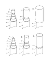
- FIG. 3(a) is a plan view of the sensor unit of this embodiment
- FIG. 3(b) is a cross-sectional view taken along line AA in FIG. 3(a).
- the sensor unit 1 includes a linear sensor assembly including the linear sensor 2 and the signal cable 28, the base 3, the lid 4, and the peripheral wall 5.
- the base 3 has a structure made of stainless steel in which a base portion 31 and a columnar portion 32 protruding from the base portion 31 are integrally formed, and a first pressing body 33 .
- the base portion 31 and the columnar portion 32 may be made of other metal such as aluminum or brass, may be made of resin such as engineering plastic, or may be made of ceramic. It is preferable that the base portion 31 and the columnar portion 32 be made of a highly rigid material so as to facilitate the transmission of vibration.
- the base 31 is made of stainless steel and has an outer diameter of 20 mm and a thickness (height) of 2 mm.
- the columnar portion 32 has a cylindrical shape with an outer diameter of 9 mm and a height of 8 mm.
- a base through-hole 3a is formed in the central portion of the base portion 31 and the columnar portion 32 along the projecting direction of the columnar portion 32 and penetrates through the base portion 31 and the columnar portion 32, respectively.
- the diameter of the base through-hole 3a is 6 mm.
- these shapes are appropriately set according to the device to be measured in which the sensor unit 1 is used.
- the columnar portion 32 may have a shape other than a cylinder, such as a prism or an elliptical column, and may have a cross-sectional shape that changes depending on the protrusion height, such as tapering toward the protrusion direction.
- the first pressing body 33 is a rubber ring having a right-angled triangular cross section, and is located at the base of the columnar part 32 between the lid 4 and the base 31 .
- the rubber which is the material of the first pressing body 33, is compounded and hardened synthetic rubber.
- the inner diameter of the first pressing body 33 is slightly smaller than the outer diameter of the columnar portion 32 .
- Two sides sandwiching a right angle in the cross section of the first pressing body 33 are in contact with the base portion 31 and the columnar portion 32, respectively.
- the oblique side of the cross section of the first pressing body 33 is inclined by about 45 degrees with respect to the projecting direction of the columnar portion 32 .
- the projecting direction of the columnar portion 32 coincides with the sandwiching direction in which the linear sensor 2 is sandwiched between the lid 4 and the base portion 31 . That is, the oblique side of the cross section of the first pressing body 33 is inclined by about 45 degrees with respect to the sandwiching direction of the lid body 4 . This oblique side forms an inclined surface on the first pressing body 33 .
- the angle of the oblique side in the cross section of the first pressing body 33 does not have to be 45 degrees, but it is preferably 25 degrees or more and 75 degrees or less, and more preferably 30 degrees or more and 70 degrees or less.
- the first pressing body 33 does not necessarily have to be inclined, and may have a surface on the linear sensor 2 side that extends in a direction perpendicular to the sandwiching direction.
- the lid body 4 sandwiches the linear sensor 2 wound around the columnar part 32 with the base part 31 via the first pressing body 33 .
- the linear sensor 2 is pushed toward the base 31 by being sandwiched by the lid 4 .
- a load is applied to the linear sensor 2 toward the side of the columnar portion 32 (radial direction of the columnar portion 32 ).
- the first pressing body 33 may have, for example, a sector shape in which the oblique side portion of the cross-sectional shape is arcuate. In the case of the fan shape, the tangential direction of the arc in the cross-sectional shape is inclined with respect to the sandwiching direction of the lid body 4, so the surface formed by the arc becomes an inclined surface.
- the first pressing member 33 may be made of natural rubber, fluororesin such as PTFE, PFA, ETFE, FEP, PVDF, high density polyethylene (HDPE), ABS, polyamide, polyimide, or other resin. good too. Moreover, it may be made of a resin to which a compound or glass fiber is added. Furthermore, the first pressing body 33 may be a foam. Since the first pressing body 33 is a portion that directly contacts the linear sensor 2 and sandwiches the linear sensor 2 between itself and the lid 4, it is made of a material that is more elastically deformable than at least the base 31. is preferred. That is, it is preferably made of a material having lower rigidity than the base portion 31 .
- the first pressing body 33 is made of a material that has a certain degree of rigidity so that the linear sensor 2 sandwiched between the base part 31 and the lid body 4 can be applied with pressure to the extent that the linear sensor 2 is slightly deformed in cross section.
- the first pressing body 33 may be made of the same material as the base portion 31 or the columnar portion 32 , or may be formed integrally with the base portion 31 or the columnar portion 32 .
- the first pressing body 33 may be made of metal. In that case, a layer of resin, rubber, or the like is applied to the contact surface with the linear sensor 2 in order to prevent the linear sensor 2 from being damaged. It is preferable to provide
- the linear sensor 2 is wound around the columnar portion 32 multiple times.
- the linear sensor 2 is wound many times from the base of the columnar portion 32 to the protruding end so as to be double-overlapped on the outside of the columnar portion 32 . That is, the linear sensor 2 makes two turns at the same height position of the columnar portion 32 . If the linear sensor 2 is wound less than one turn around the columnar portion 32, a large directivity may occur in the detection direction. Further, although the linear sensor 2 may be wound once, the sensitivity of the linear sensor 2 increases in proportion to the number of windings, and the output signal also increases. It is preferable to wind more than this. As shown in FIG.
- the peripheral wall portion 5 is formed with a draw-out hole 5h for drawing out the rear end portion of the linear sensor 2.
- the connecting portion 2b between the linear sensor 2 and the signal cable 28 is located inside the drawer hole 5h. Therefore, the lead-out hole 5 h corresponds to an example of a guide portion that guides the rear end portion of the linear sensor 2 or the signal cable 28 to the outside of the peripheral wall portion 5 .
- the connecting portion 2 b to the linear sensor 2 and the signal cable 28 may be arranged outside the peripheral wall portion 5 or may be arranged in a portion wound around the columnar portion 32 .
- the lid 4 has a lid portion 40 and a second pressing body 41.
- the lid 4 is arranged to face the base 31 .
- the lid portion 40 is made of a stainless steel structure integrally formed with the peripheral wall portion 5 .
- the lid portion 40 and the peripheral wall portion 5 may be made of other metal such as aluminum or brass, may be made of resin such as engineering plastic, or may be made of ceramic.
- the lid portion 40 has the same outer diameter as the base portion 31, and has an annular shape in which a lid portion through-hole 40a having the same diameter as the base through-hole 3a is formed in the central portion.
- the peripheral wall portion 5 has a hollow cylindrical shape with an outer diameter equal to that of the lid portion 40 and an inner diameter larger than the lid portion through-hole 40a.
- the drawing hole 5h mentioned above penetrates the inner surface and the outer surface of the peripheral wall portion 5 in a straight line.
- the inner diameter of the peripheral wall portion 5 is formed to be larger than the outer diameter of the columnar portion 32 by about 0.4 mm.
- the linear sensor 2 is slightly compressed and housed between the columnar portion 32 and the peripheral wall portion 5 . Therefore, the peripheral wall portion 5 surrounds the linear sensor 2 while being in contact with the linear sensor 2 wound around the columnar portion 32 from the side of the columnar portion 32 .
- the difference between the outer diameter of the columnar portion 32 and the inner diameter of the peripheral wall portion 5 is appropriately set according to the thickness of the linear sensor 2 and the number of turns around the columnar portion 32 .
- the height of the peripheral wall portion 5 matches the projection length of the columnar portion 32 .
- the linear sensor 2 wound around the columnar portion 32 is sandwiched between the lid portion 40 and the base portion 31 .
- the lid 4 is fixed to the base 3 with an adhesive while applying a static pressure to the linear sensor 2 wound around the columnar portion 32 .
- a storage space for storing the linear sensor 2 is formed by the base 3, the lid 4, and the peripheral wall portion 5, and the lid 4 compresses and covers the linear sensor 2 stored in the storage space.
- the lid 4 and the peripheral wall portion 5 may be fixed to the base 3 by caulking or screwing.
- the second pressing body 41 is a rubber ring having a right-angled triangular cross section, and is positioned between the lid part 40 and the base part 31 .
- the rubber which is the material of the second pressing body 41, is compounded and hardened synthetic rubber.
- the outer diameter of the second pressing body 41 is slightly larger than the inner diameter of the peripheral wall portion 5 .
- Two sides sandwiching a right angle in the cross section of the second pressing body 41 are in contact with the lid portion 40 and the peripheral wall portion 5, respectively.
- the oblique side of the cross section of the second pressing body 41 is inclined by about 45 degrees with respect to the sandwiching direction of the lid portion 40 . This oblique side forms an inclined surface on the second pressing body 41 .
- the angle of the oblique side of the cross section of the second pressing body 41 does not have to be 45 degrees, it is preferably 25 degrees or more and 75 degrees or less, and more preferably 30 degrees or more and 70 degrees or less.
- the second pressing body 41 does not necessarily have to be inclined, and may have a surface on the linear sensor 2 side that extends in a direction perpendicular to the sandwiching direction.
- the linear sensor 2 wound around the columnar portion 32 is sandwiched between the lid 4 and the base portion 31 by the second pressing member 41, so that the linear sensor 2 is pushed toward the base portion 31 in the sandwiching direction.
- a load directed toward the columnar portion 32 is also generated. Since the second pressing body 41 has an inclined surface, this load is increased. A load directed to the side of the columnar portion 32 and toward the columnar portion 32 is generated.
- the cross-sectional shape of the second pressing body 41 may be, for example, fan-shaped with an arcuate oblique side. In the case of the fan shape, the tangential direction of the arc in the cross section is inclined with respect to the sandwiching direction of the lid portion 40, so the surface formed by the arc becomes an inclined surface. Due to this inclined surface, a load is applied to the linear sensor 2 toward the columnar portion 32 side.
- the second pressing body 41 may be made of natural rubber, fluororesin such as PTFE, PFA, ETFE, FEP and PVDF, high density polyethylene (HDPE), ABS, polyamide, polyimide and other resins. good too. Moreover, it may be made of a resin to which a compound or glass fiber is added. Furthermore, the second pressing body 41 may be a foam. Since the second pressing body 41 is a portion that directly contacts the linear sensor 2 and sandwiches the linear sensor 2 between itself and the base 31 , it should be made of a material that is more elastically deformable than at least the base 31 . preferable. That is, it is preferably made of a material having lower rigidity than the base portion 31 .
- the second pressing body 41 is made of a material that has a certain degree of rigidity so that the linear sensor 2 sandwiched between the base part 31 and the lid body 4 can be applied with pressure to the extent that the linear sensor 2 is slightly deformed in cross section.
- the second pressing body 41 may be made of the same material as the lid body 4 or may be formed integrally with the lid body 4 .
- the second pressing body 41 may be made of metal. In that case, a layer of resin, rubber, or the like is applied to the contact surface with the linear sensor 2 in order to prevent the linear sensor 2 from being damaged. It is preferable to provide
- FIG. 4 is an exploded sectional view of the sensor unit shown in FIG. 3(b). This figure can also be said to be a cross-sectional view showing the state before the cover 4 is fixed to the base 3 .
- the second pressing body 41 is inserted inside the peripheral wall portion 5 until it contacts the lid portion 40 .
- the second pressing member 41 is made of rubber and has an outer diameter slightly larger than the inner diameter of the peripheral wall 5, so that it is held in contact with the lid 40 by its own elasticity.
- the first pressing body 33 is fitted into the columnar portion 32 of the base body 3 so that the first pressing body 33 is positioned at the root portion of the columnar portion 32 .
- the first pressing member 33 is made of rubber and has an inner diameter slightly smaller than that of the columnar portion 32, so that it is held at the root portion of the columnar portion 32 by its own elasticity.
- double-sided tape W is attached so as to extend over the inclined surface of the first pressing body 33 and the side surface of the columnar portion 32 .
- the double-sided tape W may be attached to the entire circumference of the side surface of the columnar portion 32, or may be attached to a portion of the side surface.
- the tip of the linear sensor 2 is temporarily attached to the double-faced tape W, and the linear sensor 2 is wound up to the protruding end of the columnar portion 32 .
- FIG. 5 is a mounting state diagram showing an example of a mounting state in which the sensor unit shown in FIG.
- a screw hole 9a is provided at the measurement location of the object 9 to be detected.
- the sensor unit 1 is fixed to the object 9 to be detected by screwing a bolt B that has passed through the base through-hole 3a and the lid through-hole 40a into the screw hole 9a. Further, the sensor unit 1 is pressed against the object 9 to be detected by a bolt B. As shown in FIG. Instead of the bolts B, the sensor unit 1 may be fixed to the detection object 9 with an adhesive, double-sided tape, or the like. You may
- the vibration is transmitted to the base 31 first.
- the linear sensor 2 is surrounded by the base portion 31 , the columnar portion 32 and the peripheral wall portion 5 , is in contact with them, and is lightly compressed by the lid portion 40 . Therefore, the vibration transmitted from the detected body 9 to the base portion 31 is easily transmitted to the linear sensor 2 from the columnar portion 32 and the peripheral wall portion 5 as well.
- the vibration having the amplitude direction other than the pinching direction can also be detected with high sensitivity.
- the sensor unit 1 described above it is possible to detect vibrations occurring in the object 9 to be detected with high sensitivity.
- the linear sensor 2 since the linear sensor 2 is pressed against not only the base portion 31 but also the peripheral wall portion 5 by the first pressing body 33, the vibration applied to the peripheral wall portion 5 from the object to be detected 9 via the base portion 31 is applied to the linear sensor 2. easily transmitted to Similarly, since the linear sensor 2 is also pressed against the columnar portion 32 by the second pressing body 41, the vibration applied to the columnar portion 32 from the detected body 9 via the base portion 31 is easily transmitted to the linear sensor 2. . With these, the vibration generated in the detected object 9 can be detected with higher sensitivity.
- the linear sensor 2 sandwiched between the first pressing body 33 and the second pressing body 41 is It can prevent you from getting hurt. Furthermore, since the peripheral wall portion 5 is formed integrally with the lid portion 40, the number of parts of the sensor unit 1 can be reduced. In addition, since the side surface of the columnar portion 32 is open before the cover 4 is attached to the base 3, and the linear sensor 2 can be easily wound around the columnar portion 32, the productivity of the sensor unit 1 is increased, and the sensor Unit 1 can be produced at low cost.
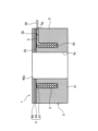
- FIG. 6 is a cross-sectional view of the sensor unit of the second embodiment.
- the sensor unit 1 shown in FIG. is different from the sensor unit 1 of the previous embodiment.
- the peripheral wall portion 5 has a hollow cylindrical shape.
- the peripheral wall portion 5 has a groove 5g which is slightly wider than the diameters of the linear sensor 2 and the signal cable 28 and slightly deeper than the diameter of the signal cable 28.
- the connecting portion 2b between the linear sensor 2 and the signal cable 28 is arranged in the groove 5g. That is, this groove 5 g corresponds to an example of a guide portion that guides the rear end portion of the linear sensor 2 or the signal cable 28 to the outside of the peripheral wall portion 5 .
- the lid body 4 has a lid portion 40 , a second pressing body 41 and a packing 43 .
- the lid portion 40 is made of an annular stainless steel plate.
- the packing 43 has a disc shape with a hole in the center, and has the same shape as the lid portion 40 in plan view.
- the packing 43 is made of a rubber sheet that is oil resistant and slightly thinner than the lid portion 40 . This packing 43 is for closing the gap between the lid portion 40 and the peripheral wall portion 5 .
- the packing 43 may be made of a material other than rubber as long as it is more deformable than the cover 40, and may be made of resin, for example.
- the packing 43 is fixed to the lid portion 40 with an adhesive.
- the surface of the packing 43 opposite to the surface fixed to the lid portion 40 is adhered to the columnar portion 32 and the peripheral wall portion 5 with an adhesive.
- a second pressing member 41 is attached between the columnar portion 32 and the peripheral wall portion 5 on the opposite surface.
- the second pressing body 41 is a rubber ring having a right-angled triangular cross-section with a right-angled apex protruding toward the base 31 side.
- the oblique side of the cross-sectional shape of the second pressing body 41 is attached to the packing 43 , and the two sides of the cross-sectional shape sandwiching the right angle are inclined 45 degrees in opposite directions to the sandwiching direction of the lid body 4 .
- These two sides form an inclined surface on the second pressing body 41 .
- the two sides sandwiching the right angle in the cross section of the second pressing body 41 may have different angles, and the inclination angle may be other than 45 degrees.
- the inclination angle of each of the two sides with respect to the sandwiching direction of the lid 4 is preferably 25 degrees or more and 75 degrees or less, and more preferably 30 degrees or more and 70 degrees or less.
- the lid 4 sandwiches the linear sensor 2 between itself and the base 31 by the second pressing member 41, so that the linear sensor 2 wound around the columnar portion 32 receives a load directed toward the columnar portion 32 and a peripheral wall pressure. A load directed toward the portion 5 is also generated.
- the cross-sectional shape of the second pressing body 41 may be fan-shaped or the like that protrudes toward the base portion 31 side.
- the tangential direction is inclined with respect to the sandwiching direction of the lid portion 40 except for the vertices of the convex shape of the cross section, so the surfaces other than the vertexes are inclined surfaces. Due to this inclined surface, a load is applied to the linear sensor 2 toward the columnar portion 32 side and the peripheral wall portion 5 side.
- the first pressing body 33 is a rubber ring having a right-angled triangular cross-section with a right-angled apex protruding toward the lid part 40 side.
- the oblique side of the cross-sectional shape of the first pressing body 33 is attached to the base portion 31 , and the two sides of the cross-sectional shape sandwiching the right angle are inclined 45 degrees in opposite directions to the sandwiching direction of the lid portion 40 . These two sides form an inclined surface on the second pressing body 41 .
- the two sides sandwiching the right angle in the cross section of the first pressing body 33 may have different angles, and the inclination angle may be other than 45 degrees.
- the inclination angle of each of the two sides with respect to the sandwiching direction of the lid 4 is preferably 25 degrees or more and 75 degrees or less, more preferably 30 degrees or more and 70 degrees or less.
- the lid 4 sandwiches the linear sensor 2 between itself and the base portion 31 by the first pressing member 33, so that the linear sensor 2 wound around the columnar portion 32 receives a load directed toward the columnar portion 32 and a peripheral wall pressure. A load directed toward the portion 5 is also generated.
- the cross-sectional shape of the first pressing body 33 may be fan-shaped or the like that protrudes toward the lid portion 40 side.
- the tangential direction is inclined with respect to the sandwiching direction of the lid portion 40 except for the vertices of the convex shape of the cross section, so the surfaces other than the vertexes are inclined surfaces. Due to this inclined surface, a load is applied to the linear sensor 2 toward the columnar portion 32 side and the peripheral wall portion 5 side.
- This second embodiment also has the same effect as the previous embodiment. Also, since the number of parts increases, the number of assembling man-hours also increases. However, instead of inserting the signal cable 28 into the lead-out hole 5h and pulling it out from the outer surface of the peripheral wall 5 during assembly, it is inserted into the groove formed in the peripheral wall 5. In addition, the assembly of the sensor unit 1 is facilitated because it only needs to be assembled.
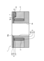
- FIG. 7 is a cross-sectional view of the sensor unit of the third embodiment.
- the sensor unit 1 shown in FIG. 7 differs from the sensor unit 1 of the second embodiment shown in FIG. 6 in that the base portion 31, the columnar portion 32, and the peripheral wall portion 5 are integrally formed. As shown in FIG. 7, the base portion 31, the columnar portion 32, and the peripheral wall portion 5 are formed by digging a circumferential groove in one end face of a hollow columnar structure made of stainless steel.
- the third embodiment has the effect of reducing the number of parts of the sensor unit 1, so that the sensor unit 1 can be produced at low cost.
- the sensor unit 1 of the fourth embodiment will be described.
- the differences from the sensor unit 1 of the previous embodiment shown in FIG. 3 will be mainly described.
- FIG. 8(a) is a plan view of the sensor unit of the fourth embodiment
- FIG. 8(b) is a cross-sectional view taken along the line BB in FIG. 8(a).
- the sensor unit 1 shown in FIGS. 8(a) and 8(b) has the shape of the lid portion 40, the penetration direction of the extraction hole 5h, the terminal member 7, and the conductive shield member 8. It differs from the sensor unit 1 shown in FIG.
- the sensor unit 2 is also different from the sensor unit 1 shown in FIG. 3 in that the linear sensor 2 is folded back at the center in the length direction and wound around the columnar portion 32 with the folded portion leading.
- a lid recess 401 is formed on the surface of the lid 40 on which the conductive shield member 8 is arranged.
- the lead hole 5h is formed obliquely from the inner peripheral surface of the peripheral wall portion 5 to the lid recessed portion 401. As shown in FIG.
- the lead hole 5h may be a hole in which a horizontal hole formed horizontally from the inner peripheral surface of the peripheral wall portion 5 and a vertical hole formed vertically from the lid recess 401 are connected. Both ends of the linear sensor 2 are passed through the extraction hole 5h.
- the terminal member 7 is arranged inside the lid recess 401 .
- One end of the signal cable 28 is also arranged in the lid recess 401 . Both ends of the linear sensor 2 and one end of the signal cable 28 are connected to the terminal member 7 .
- the terminal member 7 is a printed circuit board on which an amplifier 71 is mounted. This amplifier 71 amplifies the output signal of the linear sensor 2 and sends it to the signal cable 28 .
- the amplifier 71 amplifies the signal voltage to about ⁇ 5V.
- the amplifier 71 has a high impedance on the input side, which is the linear sensor 2 side, and a lower impedance on the output side, which is the signal cable 28 side, than the input side.
- the impedance on the input side is preferably 10 k ⁇ or more and 10 M ⁇ or less.
- the impedance on the output side is preferably 10 ⁇ or more and 100 k ⁇ or less.
- the impedance on the input side is set to 1 M ⁇ , and the impedance on the output side is set to 200 ⁇ .
- the signal input to the amplifier 71 is output from the amplifier 71 after both the voltage and current are amplified.
- the power line of the amplifier 71 is also provided in the signal cable 28 of the fourth embodiment.
- the terminal member 7 and one end portion of the signal cable 28 are continuously covered with a shield 72 .
- the shield 72 is formed by forming a film in which an electromagnetic shield layer is formed between two insulating layers into a box-like shape surrounding the terminal member 7 and one end portion of the signal cable 28 .
- This electromagnetic shield layer is electrically connected to the ground electrode of the amplifier 71 and completely electrically insulated from the lid 4 , the peripheral wall portion 5 and the conductive shield member 8 .
- the electromagnetic shield layer of the shield 72 independently covers the terminal member 7 including the amplifier 71 and one end portion of the signal cable 28, thereby eliminating the influence of external electromagnetic noise and covering the cover 4 and the like.
- the electrical operation of the amplifier 71 is stabilized even if the potential level of the contacting parts changes due to contact with the measuring device or member, and the one end portion of the signal cable 28 placed inside the electromagnetic shield layer of the shield 72 It is possible to protect the terminal member 7 and the one end portion of the signal cable 28 from a potential change exceeding the rating of the amplifier 71 and unexpectedly generated surge noise.
- the conductive shield member 8 is attached to the end face of the lid 4 with an adhesive.
- the conductive shield member 8 has a disc shape with a shield through hole 8a in the center, and is made of stainless steel and has the same shape as the lid portion 40 in a plan view. It should be noted that the conductive shield member 8 may be made of a material other than stainless steel, such as a thin metal plate or a conductive film, as long as it is conductive.
- the terminal member 7 is also electrically shielded by the conductive shield member 8 and the lid portion 40 . Therefore, intrusion of noise into the terminal member 7 is further suppressed. Moreover, since the terminal member 7 is also physically shielded by the conductive shield member 8 and the lid portion 40, damage to the terminal member 7 is suppressed.
- the amplifier 71 in addition to the same effect as the sensor unit 1 shown in FIG. 3, since the amplifier 71 is provided, the influence of noise on the output signal of the linear sensor 2 can be relatively reduced. . That is, the SN ratio in the sensor unit 1 can be increased. As a result, a stronger signal can be sent to an external measuring device or the like against noise such as external electromagnetic noise, so that a clear output signal can be obtained from the measuring device or the like. In addition, since the output signal is amplified by the amplifier 71 and the transmission power is also increased, the output signal can be delivered to a measuring instrument or the like located further away.
- the signal cable 28 uses a shielded cable using multi-core twisted wires, which is different from the cable for analog signal transmission.
- the sensor unit 1 of the fifth embodiment will be described.
- the points of difference from the sensor unit 1 of the second embodiment shown in FIG. 6 will be mainly described.
- FIG. 9 is a cross-sectional view of the sensor unit of the fifth embodiment.
- the sensor unit 1 shown in FIG. 9 differs from the sensor unit shown in FIG. 6 in the shape of the peripheral wall portion 5 and the provision of the terminal member 7 .
- the sensor unit 2 is also different from the sensor unit 1 shown in FIG. 3 in that the linear sensor 2 is folded back at the center in the length direction and wound around the columnar portion 32 with the folded portion leading.
- a peripheral wall recessed portion 51 is formed on the upper surface of the peripheral wall portion 5 .
- the groove 5 g is formed from the inner peripheral surface of the peripheral wall portion 5 to the peripheral wall recessed portion 51 .
- the width of the groove 5g is slightly wider than the width of the two linear sensors 2. As shown in FIG. Both ends of the linear sensor 2 are arranged in the groove 5g.
- the terminal member 7 is arranged inside the peripheral wall concave portion 51 .
- One end portion of the signal cable 28 is also arranged in the peripheral wall recessed portion 51 . Both ends of the linear sensor 2 and one end of the signal cable 28 are connected to the terminal member 7 .
- the terminal member 7 is a printed circuit board on which an amplifier 71 is mounted. Since this amplifier 71 is the same as that shown in FIG. 8, its description is omitted.
- the terminal member 7 and one end portion of the signal cable 28 are continuously covered with a shield 72 .
- the shield 72 is formed by forming a film in which an electromagnetic shield layer is formed between two insulating layers into a box-like shape surrounding the terminal member 7 and one end portion of the signal cable 28 .
- This electromagnetic shield layer is electrically connected to the ground electrode of the amplifier 71 and completely electrically insulated from the lid 4 and the peripheral wall 5 .
- the electromagnetic shield layer of the shield 72 independently covers the terminal member 7 including the amplifier 71 and one end portion of the signal cable 28, thereby eliminating the influence of external electromagnetic noise and covering the cover 4 and the like.
- the electrical operation of the amplifier 71 is stabilized even if the potential level of the contacting parts changes due to contact with the measuring device or member, and the one end portion of the signal cable 28 placed inside the electromagnetic shield layer of the shield 72 It is possible to protect the terminal member 7 and the one end portion of the signal cable 28 from a potential change exceeding the rating of the amplifier 71 and unexpectedly generated surge noise.
- the terminal member 7 is electrically shielded by the peripheral wall portion 5 and the lid portion 40, the intrusion of noise into the terminal member 7 is further suppressed.
- the terminal member 7 is physically shielded by the peripheral wall portion 5 and the lid portion 40, damage to the terminal member 7 is suppressed.
- this fifth embodiment also has the effect of having an amplifier 71 like the sensor unit 1 shown in FIG. 6
- FIG. 10(a) is a bottom view of the sensor unit of the sixth embodiment
- FIG. 10(b) is a cross-sectional view taken along line CC of FIG. 10(a).
- the sensor unit 1 shown in FIGS. 10(a) and 10(b) has the shape of the base 3, the shape of the lid 4, the shape of the peripheral wall 5, the terminal member 7, and the conductive properties. It differs from the sensor unit 1 shown in FIG. 3 in that a shield member 8 is provided.
- the base 3 includes a base portion 31 generally shaped like a hexagon head bolt, a columnar portion 32 protruding from the tip of the base portion 31 toward the tip side, and a first pressing member. 33.
- the lower side in FIG. 10(b) will be referred to as the front end side, and the upper side in FIG.
- the base portion 31 is composed of a base head portion 311 having a hexagonal outer shape and a base male screw 312 having a screw thread.
- a base concave portion 313 that is a rectangular concave portion is formed on the rear end side surface of the base portion 31 .
- the columnar portion 32 has a smaller diameter than the base male screw 312 . Therefore, a stepped portion is formed between the columnar portion 32 and the base male screw 312 .
- a through hole (not shown) extending from the base recess 313 to the columnar portion 32 is formed in the base 3 .
- a linear sensor 2 is passed through the through hole.
- the lid 4 has a disk-shaped lid portion 40, a second pressing body 41, and a lid screw portion 42 protruding from the lid portion 40 toward the tip side.
- the lid threaded portion 42 has a cylindrical shape with a screw thread on its outer periphery.
- the lid threaded portion 42 corresponds to an example of a threaded portion.
- the projecting direction of the lid screw portion 42 matches the projecting direction of the columnar portion 32 .
- a peripheral wall female screw 52 is provided on the rear end side of the peripheral wall portion 5 .
- a cylindrical hole into which the columnar portion 32 is inserted is formed on the distal end side of the peripheral wall portion 5 .
- the peripheral wall female thread 52 has a hollow cylindrical shape with an inner diameter slightly larger than the portion into which the columnar portion 32 is inserted.
- the base body 3 is fixed to the peripheral wall portion 5 by screwing the base male screw 312 into the peripheral wall female screw 52 . Further, by screwing the base male screw 312 into the peripheral wall female screw 52, the linear sensor 2 is sandwiched by a certain amount of pressure between the base 31 and the lid 4 via the first pressing body 33 and the second pressing body 41.
- the outer shape of the peripheral wall portion 5 is hexagonal in plan view.
- the peripheral wall portion 5 , the lid portion 40 , and the lid screw portion 42 are integrally formed, and the overall outer shape of these is generally in the shape of a hexagonal bolt that is larger than the base body 3 .
- the terminal member 7 is arranged inside the base concave portion 313 .
- One end of the linear sensor 2 and one end of the signal cable 28 are connected to the terminal member 7 . Since the terminal member 7 is the same as that shown in FIG. 8, the description thereof is omitted. Also, the terminal member 7 and the shield 72 covering one end portion of the signal cable 28 are the same as those shown in FIG.
- the conductive shield member 8 closes the rear end side of the base concave portion 313 .
- the conductive shield member 8 is made of stainless steel and has a rectangular plate shape that is one size larger than the base concave portion 313 .
- the conductive shield member 8 is fixed to the rear end side of the base concave portion 313 with an adhesive. It should be noted that the conductive shield member 8 may be made of a material other than stainless steel, such as a thin metal plate or a conductive film, as long as it is conductive.
- a U-shaped notch 8b is formed on one side of the conductive shield member 8. As shown in FIG. The notch 8b is formed slightly wider than the signal cable 28. As shown in FIG. The signal cable 28 extends outside the sensor unit 1 through the notch 8b. Intrusion of noise into the terminal member 7 is further suppressed by the conductive shield member 8 and the base portion 31 .
- the sensor unit 1 in addition to the same effect as the sensor unit 1 of the fourth embodiment shown in FIG. 8, the sensor unit 1 itself acts as a bolt, so that the sensor unit 1 can be easily attached to an object to be detected. It has the effect of being able to
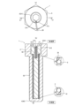
- FIG. 11(a) is a bottom view of the sensor unit of the seventh embodiment, and FIG. 11(b) is a cross-sectional view taken along line DD of FIG. 11(a).
- the sensor unit 1 shown in FIGS. 11(a) and 11(b) differs from that of FIG. is different from the sensor unit 1 shown in FIG.
- the base 3 has a generally set screw-shaped base portion 31, a columnar portion 32 projecting from the tip of the base portion 31, and a first pressing body 33. are doing.
- the lower side in FIG. 11(b) is called the front end side
- the upper side in FIG. 11(b) is called the rear end side.
- a hexagonal socket 314 into which a hexagonal wrench is fitted is formed in the surface of the rear end side of the base portion 31 .
- the outer peripheral surface of the base portion 31 is a male screw with a screw thread. Further, the base portion 31 is formed with a U-shaped groove 31a recessed from the outer peripheral surface toward the center. This U-shaped groove 31 a is formed slightly wider than the signal cable 28 .
- the columnar portion 32 protrudes from the base portion 31 toward the tip side. The columnar portion 32 has a smaller diameter than the base portion 31 . Therefore, a stepped portion is formed between the columnar portion 32 and the base portion 31 .
- a slit 315 is formed in the base 3 from the base portion 31 to the columnar portion 32 .
- the slit 315 is a bottomed rectangular hole that is open on the front side of the paper surface of FIG. 11B and closed on the back side of the paper surface. However, the slit 315 may be a through hole that is open on both the front side and the back side of the page.
- the lid body 4 has a lid portion 40 and a second pressing body 41 .
- the lid portion 40 has a disc shape, and closes the hollow hole of the peripheral wall male screw 53 with the distal end of the peripheral wall male screw 53 to be described later.
- the peripheral wall portion 5 has a hollow cylindrical shape with a small diameter on the front end side and a hollow cylindrical shape with a larger diameter on the rear end side than the rear end side.
- a rear end side of the large-diameter portion of the peripheral wall portion 5 forms a peripheral wall female screw 52 having a screw thread formed on the inner peripheral surface.
- the base 3 is fixed to the peripheral wall portion 5 by screwing the base portion 31 into the peripheral wall female screw 52 .
- a small-diameter portion of the peripheral wall portion 5 is a peripheral wall male screw 53 having a screw thread formed on the outer peripheral surface.
- a hole is formed in the distal end side of the large-diameter portion of the peripheral wall portion 5 and the peripheral wall male screw 53 .
- the columnar portion 32 is inserted into the hole.
- the linear sensor 2 By screwing the base portion 31 of the base body 3 into the peripheral wall female screw 52 of the peripheral wall portion 5 , the linear sensor 2 can be moved to some extent by the base portion 31 and the lid member 4 via the first pressing member 33 and the second pressing member 41 . pinched by pressure.
- the outer shape of the large-diameter portion of the peripheral wall portion 5 is hexagonal in plan view.
- the peripheral wall portion 5 and the lid portion 40 are integrally formed, and the overall outer shape of these is generally in the shape of a hexagonal bolt.
- the terminal member 7 is arranged inside the slit 315 .
- One end of the linear sensor 2 and one end of the signal cable 28 are connected to the terminal member 7 .
- the linear sensor 2 extends toward the columnar portion through the open surface of the slit 315 and is wound around the columnar portion 32 . Since the terminal member 7 is the same as that shown in FIG. 8, the description thereof is omitted. Also, the terminal member 7 and the shield 72 covering one end portion of the signal cable 28 are the same as those shown in FIG. In addition, since the terminal member 7 is entirely surrounded by the base 3 and the peripheral wall portion 5, intrusion of noise is further suppressed.
- the signal cable 28 extends outside the sensor unit 1 through the U-shaped groove 31a.
- a part of the linear sensor 2 can be inserted inside the object to be detected. 1 has the effect of being able to detect vibration with higher detection sensitivity.
- the present invention is not limited to the above-described embodiments, and can be modified in various ways within the scope of the claims.
- the linear sensor 2 using the piezoelectric body 22 has been described in the present embodiment, the linear sensor 2 may be changed to a linear sensor 2 using a resistance wire such as a conductive rubber, a capacitor wire, or the like.
- a resistance wire such as a conductive rubber, a capacitor wire, or the like.
- one or both of the first pressing body 33 and the second pressing body 41 may be omitted.
- the outer shapes of the base portion 31, the columnar portion 32, and the lid portion 40 may not be circular in plan view, and may be polygonal, for example.
- the lid portion 40 is shown in FIG.
- the sensor unit 1 may be attached in the opposite direction to the example.
- the linear sensor 2 may be folded back at the center in the length direction, and the linear sensor 2 may be wound around the columnar portion 32 with the folded portion leading.
- the insulating members 291 and 293, the conductor members 292 and 294, and the cover member 295 at the tip of the linear sensor 2 may be omitted, and both the tip and the rear end of the linear sensor 2 may be connected to the signal cable 28. .
- the inner conductor 21 at the front end and the rear end of the linear sensor 2 are both connected to the signal line of the signal cable 28, and the outer conductor 23 at the front end and the rear end of the linear sensor 2 are both connected to the signal ground line of the signal cable 28.
- both the front end and rear end shield coverings 25 of the linear sensor 2 are preferably connected to the ground wire in the signal cable 28 .
Landscapes
- Physics & Mathematics (AREA)
- General Physics & Mathematics (AREA)
- Geophysics And Detection Of Objects (AREA)
Abstract
本発明は、検出感度の高いセンサユニットを提供することを目的とする。本発明のセンサユニット1は、基部31とその基部31から突出した柱状部32を有する基体3と、柱状部32に巻き付けられた線状センサ2と、柱状部32の側方から線状センサ2に接した状態で線状センサ2を囲む周壁部5と、基部31に対向して配置され、基部31との間で線状センサ2を挟み込んだ蓋体4とを備えていることを特徴とする。
Description
本発明は、線状センサを備えたセンサユニットに関する。
内部導体と、その内部導体の外周面に接触して設けられた圧電体と、その圧電体の外周面に接触して設けられた外部導体とをセンサ線として用いた線状センサが知られている(例えば、特許文献1等参照)。この線状センサは、外部から荷重が加わることで圧電体が変形し、内部導体と外部導体との間に電圧が誘起されるという特性を有している。この特性を利用して、圧力を検知するための圧力センサや振動を検知するための振動センサとして線状センサを利用することが検討されている。また、圧電体を用いたセンサ線の代わりに、導電ゴム等の抵抗線やキャパシタ線等をセンサ線として用いて線状センサを構成することも検討されている。一方、近年では工作機械の振動などの状態情報を収集して分析することで、工作機械に用いられている工具などの消耗部品の劣化や工作機械の故障を事前に予測したり、より効率的に部品交換を実施するためのメンテナンス計画を立案する技術が求められている。また、ロボット、農業機械、車、家電などの装置においても状態情報を収集して分析することで故障予測やメンテナンス作業の効率化を行うことが検討されている。以下、工作機械、ロボット、農業機械、車、家電などの機器を総称して被検出体と称する。さらに、線状センサと、その線状センサを間に挟み込んだ2つの部材とから構成されるセンサユニットを用いることも検討されている(例えば、特許文献2等参照)。
しかしながら、特許文献2に記載のセンサユニットは、線状センサを単に2つの部材の間に挟み込んでいるだけなので、2つの部材の挟み込み方向にのみ線状センサと各部材が接触している。このため、その挟み込み方向以外に振幅方向を有する振動に対する検出感度が低いという問題がある。
本発明は上記事情に鑑み、検出感度の高いセンサユニットを提供することを目的とする。
上記目的を解決する本発明のセンサユニットは、基部と該基部から突出した柱状部を有する基体と、
前記柱状部に巻き付けられた線状センサと、
前記柱状部の側方から前記線状センサに接した状態で該線状センサを囲む周壁部と、
前記基部に対向して配置され、前記基部との間で前記線状センサを挟み込んだ蓋体とを備えたことを特徴とする。
前記柱状部に巻き付けられた線状センサと、
前記柱状部の側方から前記線状センサに接した状態で該線状センサを囲む周壁部と、
前記基部に対向して配置され、前記基部との間で前記線状センサを挟み込んだ蓋体とを備えたことを特徴とする。
前記基体と前記周壁部によって前記線状センサを取り囲んだ状態で、前記蓋体と前記基部の間に該線状センサが挟み込まれるので、該線状センサが、該蓋体と該基部だけでなく、前記柱状部および該周壁部にも押し付けられる。このため、被検出体からこのセンサユニットに伝わった振動が前記柱状部および前記周壁部からも前記線状センサに伝達されやすい。その結果、前記蓋体の挟み込み方向に振幅方向を有する振動に加え、挟み込み方向以外に振幅方向を有する振動も前記線状センサによって高い感度で検出できるので、このセンサユニット全体として高い検出感度で振動を検出できる。
ここで、前記蓋体は、前記線状センサを前記基部に押し付けるものであってもよい。また、前記蓋体は、前記柱状部の突出方向とは反対方向に向かって線状センサを押し付けるものであってもよい。加えて、前記蓋体は、前記線状センサを微小変形させる程度に該線状センサを押し付けるものであってもよい。さらに、前記線状センサは、信号ケーブルが接続されたものであり、前記周壁部は、前記線状センサまたは前記信号ケーブルを前記周壁部の外部に案内する案内部を有するものであってもよい。またさらに、前記線状センサは、前記柱状部に複数周巻き付けられたものであってもよい。また、前記基部は、前記線状センサよりも剛性の高いものであってもよい。同様に、前記柱状部も前記線状センサよりも剛性の高いものであってもよい。また同様に、前記周壁部も前記線状センサよりも剛性の高いものであってもよい。
本発明のセンサユニットにおいて、前記基体は、第1押圧体を有するものであり、
前記蓋体は、前記第1押圧体を介して前記基部との間で前記線状センサを挟み込むものであってもよい。
前記蓋体は、前記第1押圧体を介して前記基部との間で前記線状センサを挟み込むものであってもよい。
また、本発明のセンサユニットにおいて、前記第1押圧体は、前記基部よりも弾性変形しやすい材質で構成されたものであってもよい。
前記蓋体と前記第1押圧体との間に挟み込まれた前記線状センサが傷つくことを抑制できる。
ここで、前記第1押圧体は、ゴムなどの弾性体で構成されていてもよい。
さらに、本発明のセンサユニットにおいて、前記第1押圧体は、前記蓋体の挟み込み方向に対して傾斜した傾斜面が形成されたものであってもよい。
前記第1押圧体の傾斜面によって、前記線状センサが、前記柱状部および前記周壁部のうち少なくとも一方にも押し付けられるので、被検出体から該柱状部および該周壁部に伝わった振動が、前記線状センサに伝達されやすくなる。その結果、このセンサユニットの検出感度がより高まる。
本発明のセンサユニットにおいて、前記蓋体は、第2押圧体を有し、該第2押圧体によって前記線状センサを前記基部との間に挟み込むものであってもよい。
また、本発明のセンサユニットにおいて、前記第2押圧体は、前記基部よりも弾性変形しやすい材質で構成されたものであってもよい。
前記基部と前記第2押圧体との間に挟み込まれた前記線状センサが傷つくことを抑制できる。
ここで、前記第2押圧体は、ゴムなどの弾性体で構成されていてもよい。
前記第2押圧体は、前記蓋体の挟み込み方向に対して傾斜した傾斜面が形成されたものであってもよい。
前記第2押圧体の傾斜面によって、前記線状センサが、前記柱状部および前記周壁部のうち少なくとも一方にも押し付けられるので、被検出体から、該柱状部および該周壁部に伝わった振動が、前記線状センサに伝達されやすくなる。その結果、このセンサユニットの検出感度がより高まる。
また、本発明のセンサユニットにおいて、前記周壁部は、前記蓋体と一体に形成されたものであってもよい。
このセンサユニットの部品点数が少なくなる上に、前記周壁部と一体に形成された前記蓋体が取り付けられる前の状態では前記柱状部の側面が開放されているので、前記線状センサを前記柱状部に巻き付けやすい。このため、このセンサユニットを安価に生産できる。
また、本発明のセンサユニットにおいて、前記周壁部は、前記基体と一体に形成されたものであってもよい。
このセンサユニットの部品点数が少なくなるので、センサユニットを安価に生産できる。
また、本発明のセンサユニットにおいて、前記蓋体は、ネジ部を有するものであってもよい。
前記ネジ部によって、このセンサユニットを被検出体に容易に取り付けることができる。
また、本発明のセンサユニットにおいて、前記周壁部は、外周面にネジ山が形成されたものであってもよい。
前記周壁部に形成されたネジ山によって、このセンサユニットを被検出体に容易に取り付けることができる。
本発明によれば、検出感度の高いセンサユニットを提供することができる。
以下、図面を参照して本発明の実施の形態を説明する。先ず、本実施形態のセンサユニットに用いられる線状センサについて説明する。
図1は、線状センサの構造を示す断面図である。
図1に示すように、線状センサ2は、センサ線20と、内側シース24と、シールド被覆25と、外側シース26とを備えている。センサ線20は、内部導体21と圧電体22と外部導体23とから構成されている。図1に示すように、内部導体21は、線状センサ2の中心に配置されており、7本の導体線211で構成されている。圧電体22は、内部導体21の外周に設けられている。外部導体23は、圧電体22の外周に設けられている。
7本の導体線211は、いずれも直径が10μmのものであって、このうち4本はステンレス製の導体線211Sであり、残りの3本は銅製の導体線211Cである。図1では、ステンレス製の導体線211Sが左下がりのハッチングで、銅製の導体線211Cが右下がりのハッチングでそれぞれ示されている。図1に示す内部導体21では、中心に配置される導体線には、ステンレス製の導体線211S(ステンレスワイヤ)が用いられており、外周に配置される導体線には、ステンレス製の導体線211Sと銅製の導体線211Cが交互に用いられている。銅製の導体線211Cは、ステンレス製の導体線211Sに比べて、電気抵抗が低く、かつ柔らかい。反対に、ステンレス製の導体線211Sは、銅製の導体線211Cに比べて、電気抵抗は高くなるが、機械的強度(例えば、引張強度等)および剛性は高くなる。
7本の導体線211は、正六角形の各頂点およびその正六角形の中心に配置された状態になっている。これらの7本の導体線211は、一本に撚り合わされた状態のものである。すなわち、内部導体21は、7本の導体線211をその断面において最密構造に配置した上で撚り合わせたものである。なお、この場合の内部導体21の太さは最大30μmとなる。このように複数本の導体線211を甘撚、あるいは中撚程度に撚っておくことで、撚りの方向とは逆方向の緩みを許容し、線状センサ2に柔軟性を与えることができる。
なお、導体線211の直径は10μmに限られず、8μm以上40μm以下であってもよく、8μm以上30μm以下にすることが好ましい。導体線211は、細ければ細いほど柔軟性は高められるが強度および剛性が低下し、太ければ太いほど柔軟性は低下するが強度および剛性が高められる。また、導体線211の太さが20μm以上であれば、低コストで製造することができ、且つ製造も容易である。また、異なる太さの導体線211を撚り合わせて内部導体21を構成してもよい。
なお、図1に示す内部導体21は、7本の導体線211を撚り合わせたものであるが、この数については7本でなくてもよい。複数の導体線211を撚り合わせることにより、線状センサ2の柔軟性を高めることができる。また例えば、複数本を撚り合わせた束を複数用意し、これらをさらに撚り合わせる、といったように複数段階に分けて撚り合わせものであってもよい。例えば、7本の細い導体線211を撚り合わせた束を7本用意し、その束をさらに撚り合わせた構成にしてもよい。複数段階に分けて撚り合わせることで、線状センサ2の柔軟性がより高まるので、線状センサ2に加わった振動等に応じて線状センサ2が変形しやすくなる。その結果、線状センサ2における検出感度を高めることができる。なお、複数段階に分けて撚り合わせる場合のように、撚り合わせの工程が複数回ある場合には、撚り合わせる方向を異ならせてもよい。一方、複数の導体線211を撚り合わせずに、直線状に束にしたものを用いてもよい。また、例えば、撚り合わせない複数の導体線211の束と、撚り合わせた複数の導体線211を撚り合わせる、といったように、これらの構成を組み合わせてもよい。これらの場合であっても、圧電材料を塗布することで、複数の導体線211が互いに接着されて束ねられ、一本の圧電性繊維を製造することができる。
以上説明したセンサ線20では、内部導体21を構成する導体線211として、機械的強度や電気抵抗が異なる複数種類の導体線が用いられているが、柔軟性をさらに高める場合や、電気抵抗をさらに低くする場合には、中心の導体線211を、銅製の導体線211Cに代えてもよく、あるいは、7本の導体線211の全てを銅製の導体線211Cにしてもよい。反対に、機械的強度および剛性をさらに高める場合には、7本の導体線211の全てをステンレス製の導体線211Sにしてもよい。また、ステンレス製の導体線211Sに代えて、タングステン製の導体線や、タングステン及びその合金等の高張力鋼材あるいは超高張力鋼からなる導体線を用いてもよいし、銅製の導体線211Cに代えて、チタン製の導体線や、チタン合金あるいはマグネシウムやマグネシウム合金等からなる導体線を用いてもよい。さらには、カーボンナノチューブを含む導体線であってもよいし、ピッチ系炭素繊維を含む導体線であってもよい。あるいは、弾性変形しやすいバネ鋼材からなる導体線を用いてもよい。
圧電体22は、ポリフッ化ビニリデン(PVDF)等の圧電材料を内部導体21に塗布することによって形成されたものである。ポリフッ化ビニリデンは、圧電効果が発生する軽量の高分子材料であり、これに圧力を加えると電圧が発生し、電圧を加えると歪が発生する特性を備えている。圧電体22には分極処理が施されており、振動等によって圧電体22に変形が生じたときに内部導体21と外部導体23の間に電圧が誘起される。
図1に示す圧電体22を構成する圧電材料としては、ポリフッ化ビニリデンの他に、トリフルオロエチレン(TrEF)や、PVDFとTrEFの混晶材料や、ポリ乳酸、ポリ尿酸、ポリアミノ酸等の双極子モーメントをもつ高分子材料があげられる。また、圧電材料を塗布する方式としては、浸漬(ドブ付け)塗装であってもよいしスプレー等による吹き付け塗装であってもよいしハケ塗りであってもよいし、コーター等による塗布装置による塗布であってもよい。なお、塗布する構成に限らず、例えば、帯状のPVDFフィルムを内部導体21に螺旋状に巻き付けた構成であってもよい。
圧電体22の厚みは、導体線211の直径以上であることが好ましい。図1に示す圧電体22の厚さは、最も薄い箇所で10μmであるが、10μm以上50μm以下であることが好ましい。なお、圧電体22の厚さは、厚ければ厚いほど検出感度が良好になるが、圧電体22の厚さの限界値は、塗布する圧電材料の粘度や塗布方法によって決まってくる。また、圧電体22の厚さが厚すぎると線状センサ2が硬くなりすぎてしまい柔軟性に欠けてしまうといった欠点もある。
図1に示す内部導体21では、複数の導体線211を撚り合わせているため、導体線211同士の境目に窪みがある。この窪みの部分では、より多くの圧電材料を担持することができ、圧電材料の体積が大きく(厚く)なるため、検出感度が他の部分よりも良好になる。内部導体21には、こうした窪みによって圧電材料が他の部分よりも厚い部分が6か所、周方向に均等間隔で存在するため、どの方向に曲げられても高感度な圧電性繊維として機能する要因になる。
なお、図1に示す隣り合う導体線211は互いにほぼ接しているが、わずかな隙間から毛細管現象によって圧電材料が浸透し、隣り合う導体線211同士の隙間(内部導体21の内部)が圧電材料によって埋められた状態になっている。ただし、圧電材料の粘度や塗布方法によっては、隣り合う導体線211同士の隙間に圧電材料が浸透しない場合もある。この場合でも、内部導体21の外周に面した部分に圧電材料が担持された状態となっていればよい。なお、上述した帯状のPVDFフィルムを圧電体22として用いた構成では、隣り合う導体線211同士の隙間に圧電材料が浸透していない線状センサ2になる。この線状センサ2では、隣り合う導体線211同士の隙間に圧電材料が浸透しているものと比較して線状センサ2の柔軟性が高まるので、線状センサ2における検出感度が高まる。
図1に示す外部導体23は、圧電体22の外周に、カーボンナノチューブ等のカーボンを含む高分子導電性材料が塗布されることで形成されている。外部導体23を形成する導電性材料としては、銀の微粒子を含む高分子導電性材料や銀ペースト等であってもよい。また、この導電性材料を塗布する方式としては、浸漬(ドブ付け)塗装であってもよいしスプレー等による吹き付け塗装であってもよいしハケ塗りであってもよいし、コーター等による塗布装置による塗布であってもよい。外部導体23の厚さは、導体線211の直径以下であることが好ましく、また、圧電体22の厚さ以下であることも好ましい。図1に示す外部導体23の厚さは、5μmであるが、5μm以上50μm以下であることが好ましい。また、外部導体23に導電性材料を用いずに導線を用いてもよい。
内側シース24は、耐摩耗性、耐薬品性、防錆性を高めるために外部導体23の外周を覆っている。この内側シース24は、厚さが6μmに形成されている。内側シース24は、外側シース26に比べて柔らかい材料で構成されている。この内側シース24は、ポリアミド合成樹脂を塗布することで形成されているが、ポリ塩化ビニル樹脂を塗布することで形成してもよい。
シールド被覆25は、ニッケルメッキ銅やステンレスなどの金属製の細線を編組してチューブ状にしたシールドである。なお、シールド被覆25は、内部導体21と圧電体22と外部導体23を内側に有する内側シース24に、蒸着によって銅やアルミニウム等を蒸着させることで形成してもよい。また、シールド被覆25は、スパッタ、EBD(電子線ビーム蒸着)、CVD(気相成長法)、塗布、浸漬(ドブ付け)、無電解メッキ、接着剤による接着等の他の方法を用いて内側シース24に付着させてもよく、金属箔を巻き付けることで形成してもよい。
外側シース26は、内側シース24に比べて耐摩耗性が高い材料で構成されている。この外側シース26は、ポリテトラフルオロエチレン(PTFE)を塗布することで形成されている。ただし、4フッ化・6フッ化プロピレン フッ素樹脂(FEP)、4フッ化エチレンエチレン共重合(EPFE)、または4フッ化エチレンパーフロロアルコキシエチレン共重合 フッ素樹脂(PFA)を塗布することで形成してもよい。ここにいう塗布とは、浸漬(ドブ付け)塗装であってもよいし吹き付け塗装であってもよいしハケ塗りであってもよいし、コーター等による塗布装置による塗布であってもよい。また、ピンホールが発生することを考慮して複数回塗布することが好ましい。また、外側シース26は、内側シース24よりも厚くてもよい。さらに、内側シース24は、可燃性材料で形成されていてもよいが、外側シース26は、難燃性材料、不燃性材料、耐炎性材料で形成されていることが好ましい。
図1に示す線状センサ2の直径は0.1mmである。ただし、線状センサ2の直径はさらに太くてもよく細くてもよく、0.1~3.0mmであることが好ましい。
線状センサ2の端部の一方は、信号ケーブル28(図3参照)に接続されている。以下、信号ケーブル28に接続される側の端部を線状センサ2の後端部と称することがある。信号ケーブル28内には、信号線と、シグナルグランド線と、アース線とが設けられている。内部導体21は、信号ケーブル28内の信号線に接続され、外部導体23は信号ケーブル28内のシグナルグランド線に接続され、シールド被覆25は、信号ケーブル28内のアース線に接続されている。信号ケーブル28は、線状センサ2で得られた信号を不図示の測定装置等に伝達するためのものである。線状センサ2と信号ケーブル28によって線状センサアッシーが構成されている。
図2は、線状センサの端部のうち信号ケーブルに接続されていない側の端部について、絶縁部材および導体部材を施した例を示す図である。以下、信号ケーブル28に接続されていない側の端部を線状センサ2の先端部と称することがある。線状センサ2の先端部には、絶縁部材291、293、導体部材292、294、カバー部材295が取り付けられているが、各構造が理解しやすいよう、この図では、図2(A)から(F)まで各部材の取付状態を段階的に示している。なお、図2(A)では、内部導体21を、ひとまとまりにして円柱形状で示している。
図2(A)では、内部導体21、外部導体23、シールド被覆25が露出した線状センサ2の先端部が示されている。図2(B)には、図2(A)で示す内部導体21ごと圧電体22までが絶縁部材291で覆われた様子が示されている。この例では、絶縁部材291が圧電体22まで覆っているため、外部導体23およびシールド被覆25から内部導体21を確実に絶縁した状態にすることができる。なお、図2(B)では、各部材の位置関係を理解しやすいように圧電体22の一部が露出しているように示しているが、圧電体22は、絶縁部材291によって完全に覆われていても良い。
図2(C)には、図2(B)で示す状態から、絶縁部材291ごと外部導体23までが導体部材292で覆われた様子が示されている。この例では、外部導体23と導体部材292の電位は同じになる。この導体部材292により、内部導体21が外部ノイズの影響を受けにくくなる。なお、図2(C)では、各部材の位置関係を理解しやすいように外部導体23の一部が露出しているように示しているが、外部導体23は、導体部材292によって完全に覆われていても良い。
図2(D)には、図2(C)で示す状態から、導体部材292ごと内側シース24までが絶縁部材293で覆われた様子が示されている。この例では、絶縁部材293が内側シース24まで覆っており、他の導体から外部導体23を確実に絶縁した状態とすることができる。なお、図2(D)では、各部材の位置関係を理解しやすいように内側シース24の一部が露出しているように示しているが、内側シース24は、絶縁部材293によって完全に覆われていても良い。
図2(E)には、図2(D)で示す状態から、絶縁部材293ごとシールド被覆25までが導体部材294で覆われた様子が示されている。この例では、シールド被覆25と導体部材294の電位は同じになる。この導体部材294により、内部導体21および外部導体23がシールドされ、外部ノイズの影響を受けにくくなる。なお、図2(E)では、各部材の位置関係を理解しやすいようにシールド被覆25の一部が露出しているように示しているが、シールド被覆25は、導体部材294によって完全に覆われていても良い。
図2(F)には、図2(E)で示す状態から、導体部材294ごと外側シース26までがカバー部材295(外側シース26と同様の素材)で覆われた様子が示されている。この例では、絶縁部材291、293および導体部材292、294が設けられた線状センサ2の先端部を保護することができる。なお、このカバー部材295を熱収縮(あるいは熱融着)する素材で構成しておき、線状センサ2の先端部を覆った状態で加熱することで密着させてもよい。
絶縁部材291、293は、絶縁性の素材(例えば、塩化ビニル、ポリエチレン、等)であればよい。また、導体部材292、294は導電性の素材(例えば、アルミ、銅、錫、あるいは複数材料による合金、等)であればよい。導体部材292、294の形状については、フィルム状やメッシュ状の他、筒状の棒端子を用いてもよく、その形状が限定されるものではない。
なお、絶縁部材291、293、導体部材292、294、カバー部材295は、カバー部材295だけを用いたり、導体部材292を除いたりする、といったように、全て使用しなくともよい。また、上述の例に限らず、例えば、外側シース26を除く端面が同一面になるように切断した場合には、外側シース26を除く先端部を絶縁部材で覆い、その上をシールド被覆25と接するように導体部材で覆い、さらにカバー部材を設ける、といった構成であってもよい。また、内部導体21、圧電体22、外部導体23、内側シース24を、シールド被覆25よりも短く切断し、これらを絶縁した上でシールド被覆25で包み、さらにカバー部材を設ける、といった構成であってもよい。すなわち、導体同士の絶縁およびシールドをより確実にする構成であればよく、その構成が限定されるものではない。
図3(a)は、本実施形態のセンサユニットの平面図であり、図3(b)は、同図(a)のA-A断面図である。
図3(b)に示すように、センサユニット1は、上述した線状センサ2と信号ケーブル28からなる線状センサアッシーと、基体3と、蓋体4と、周壁部5とを備えている。基体3は、基部31とその基部31から突出した柱状部32とが一体に形成されたステンレス製の構造体と、第1押圧体33とを有している。なお、基部31および柱状部32は、アルミや黄銅など他の金属製であってもよく、エンジニアリングプラスチックなどの樹脂製であってもよく、セラミック製であってもよい。基部31および柱状部32は、振動を伝達しやすくするため剛性の高い材質で構成されていることが好ましい。基部31は、外径20mm、厚さ(高さ)2mmのステンレス製の環状をしている。柱状部32は、外径が9mmで高さが8mmの円柱状をしている。基部31および柱状部32の中心部分には、柱状部32の突出方向に沿って形成され、基部31と柱状部32それぞれを貫通した基体貫通孔3aが形成されている。基体貫通孔3aの直径は、6mmである。ただし、これらの形状は、このセンサユニット1が使用される測定対象の機器に対応して適宜設定される。例えば、柱状部32は、角柱や楕円柱など円柱以外の形状であってもよく、突出方向に向かって先細りになるなど突出高さによって断面形状が変化していてもよい。
第1押圧体33は、断面が直角三角形をしたゴム製のリングであり、柱状部32の根本部分であって、蓋体4と基部31の間に位置するように配置されている。第1押圧体33の材質であるゴムは、コンパウンド入りで固めの合成ゴムである。第1押圧体33の内径は、柱状部32の外径よりもほんの少し小さい径に形成されている。第1押圧体33の断面における直角を挟む2辺はそれぞれ基部31と柱状部32に接している。第1押圧体33の断面における斜辺は、柱状部32の突出方向に対して約45度傾斜している。この柱状部32の突出方向は、蓋体4が線状センサ2を基部31との間で挟み込む挟み込み方向と一致している。すなわち、第1押圧体33の断面における斜辺は、蓋体4の挟み込み方向に対して約45度傾斜している。この斜辺によって第1押圧体33に傾斜面が形成される。なお、第1押圧体33の断面における斜辺の角度は45度でなくても構わないが、25度以上75度以下であることが好ましく、30度以上70度以下であることがより好ましい。ただし、第1押圧体33は、必ずしも傾斜している必要はなく、挟み込み方向に対して直交方向に延在する面を線状センサ2側に有するものであってもよい。
蓋体4は、第1押圧体33を介して基部31との間で柱状部32に巻き付けられた線状センサ2を挟み込んでいる。この蓋体4による挟み込みによって、線状センサ2は、基部31側に押し込まれている。そして、線状センサ2が第1押圧体33の傾斜面に押し付けれることで、線状センサ2には柱状部32の側方(柱状部32の径方向)に向かう荷重が生じている。なお、第1押圧体33は、例えば断面形状における斜辺部分が円弧状になった扇状をしていてもよい。扇状の場合、断面形状における円弧の接線方向が蓋体4の挟み込み方向に対して傾斜することになるため、その円弧によって形成されている面が傾斜面になる。この傾斜面により、線状センサ2に柱状部32の側方に向かう荷重が生じる。第1押圧体33が傾斜面を有することでこの荷重は強くなるが、傾斜面が存在していない場合であっても線状センサ2の断面形状が円形であるため、ある程度線状センサ2に柱状部32の側方および柱状部32側に向かう荷重が生じる。
なお、第1押圧体33は、天然ゴムであってもよく、PTFE、PFA、ETFE、FEP、PVDFなどのフッ素樹脂、高密度ポリエチレン(HDPE)、ABS、ポリアミド、ポリイミドなどの樹脂製であってもよい。また、コンパウンドやグラスファイバーなどが添加された樹脂製であってもよい。さらに、第1押圧体33は、発泡体であってもよい。第1押圧体33は、線状センサ2に直接接触して蓋体4との間で線状センサ2を挟み込む部分であるため、少なくとも基部31よりも弾性変形しやすい材質で構成されていることが好ましい。すなわち、基部31よりも剛性が低い材質であることが好ましい。ただし、第1押圧体33は、ある程度の剛性を有することで、基部31と蓋体4との間に挟み込まれた線状センサ2が断面において微小変形する程度に圧力が加えられるような材質であることが好ましい。加えて、第1押圧体33は、基部31または柱状部32と同一材料で形成されてものであってもよく、基部31または柱状部32と一体に形成されたものであってもよい。第1押圧体33は金属で構成されていてもよいが、その場合、線状センサ2が傷つくことを抑制するために、線状センサ2との接触面に表面に樹脂やゴムなどの層を設けることが好ましい。
線状センサ2は、柱状部32に複数周巻き付けられている。本実施形態では、線状センサ2は、柱状部32の外側に2重に重なるように柱状部32の根本から突出端まで多数周巻き付けられている。すなわち、線状センサ2は、柱状部32の同一高さ位置に2周周回している。なお、線状センサ2の、柱状部32への巻き付け周回数が1周未満であると検出方向に大きな指向性が生じることがあるので1周以上巻き付けることが好ましい。また、線状センサ2の巻き付け周回数は1周でもよいが、巻き付け周数に比例して線状センサ2の感度が高まり出力される信号も大きくなるため、線状センサ2は、少なくとも2周以上巻き付けることが好ましい。周壁部5には、図3(a)に示すように、線状センサ2の後端部を引き出すための引出孔5hが形成されている。この実施形態では、線状センサ2と信号ケーブル28の接続部2bは、引出孔5h内に位置している。従って、引出孔5hは、線状センサ2の後端部または信号ケーブル28を周壁部5の外側に案内する案内部の一例に相当する。なお、線状センサ2と信号ケーブル28への接続部2bは、周壁部5よりも外側に配置されていてもよく、柱状部32に巻き付けられた部分に配置されていてもよい。
図3(b)に示すように、蓋体4は、蓋部40と第2押圧体41とを有している。蓋体4は、基部31に対向して配置されている。蓋部40は、周壁部5と一体に形成されたステンレス製の構造体で構成されている。なお、蓋部40および周壁部5は、アルミや黄銅など他の金属製であってもよく、エンジニアリングプラスチックなどの樹脂製であってもよく、セラミック製であってもよい。蓋部40は、外径が基部31と同一径で、中心部分に基体貫通孔3aと同一径の蓋部貫通孔40aが形成された環状をしている。周壁部5は、外径が蓋部40と同一径で、内径が蓋部貫通孔40aよりも大きい中空円筒状をしている。上述した引出孔5hは、この周壁部5の内面と外面を直線状に貫通している。また、周壁部5の内径は、柱状部32の外径よりも、0.4mm弱程度大きな径に形成されている。線状センサ2は、柱状部32と周壁部5との間で少し圧縮されて収納されている。従って、周壁部5は、柱状部32の側方から、柱状部32に巻き付けられた線状センサ2に接した状態で線状センサ2を囲んでいる。なお、線状センサ2の太さや柱状部32への周回数に応じて、柱状部32の外径と周壁部5の内径の差は適宜設定される。周壁部5の高さは、柱状部32の突出長と一致している。柱状部32に巻き付けられた線状センサ2は、蓋部40と基部31との間に挟み込まれている。蓋体4は、柱状部32に巻き付けられた線状センサ2に静的な圧力を加えた状態で、接着剤によって基体3に固定されている。換言すれば、基体3と蓋体4と周壁部5によって、線状センサ2を収納する収納空間が形成され、蓋体4がその収納空間に収納された線状センサ2を圧縮しつつ覆っている。なお、蓋体4および周壁部5はカシメやねじ止めによって基体3に固定してもよい。
第2押圧体41は、断面が直角三角形をしたゴム製のリングであり、蓋部40と基部31の間に位置するように配置されている。第2押圧体41の材質であるゴムは、コンパウンド入りで固めの合成ゴムである。第2押圧体41の外径は、周壁部5の内径よりもほんの少し大きな径に形成されている。第2押圧体41の断面における直角を挟む2辺はそれぞれ蓋部40と周壁部5に接している。第2押圧体41の断面における斜辺は、蓋部40の挟み込み方向に対して約45度傾斜している。この斜辺によって第2押圧体41に傾斜面が形成される。なお、第2押圧体41の断面における斜辺の角度は45度でなくても構わないが、25度以上75度以下であることが好ましく、30度以上70度以下であることがより好ましい。ただし、第2押圧体41は、必ずしも傾斜している必要はなく、挟み込み方向に対して直交方向に延在する面を線状センサ2側に有するものであってもよい。
蓋体4が、この第2押圧体41によって柱状部32に巻き付けられた線状センサ2を基部31との間で挟み込むことで、その線状センサ2には、挟み込み方向である基部31側に向かう荷重だけでなく柱状部32側に向かう荷重も生じている。第2押圧体41が傾斜面を有することでこの荷重は強くなるが、傾斜面が存在していない場合であっても線状センサ2の断面形状が円形であるため、ある程度線状センサ2に柱状部32の側方および柱状部32側に向かう荷重が生じる。なお、第2押圧体41の断面形状は、例えば斜辺が円弧状になった扇状などにしてもよい。扇状の場合、断面における円弧の接線方向が蓋部40の挟み込み方向に対して傾斜することになるため、その円弧によって形成されている面が傾斜面になる。この傾斜面により、線状センサ2に柱状部32側に向かう荷重が生じる。
なお、第2押圧体41は、天然ゴムであってもよく、PTFE、PFA、ETFE、FEP、PVDFなどのフッ素樹脂、高密度ポリエチレン(HDPE)、ABS、ポリアミド、ポリイミドなどの樹脂製であってもよい。また、コンパウンドやグラスファイバーなどが添加された樹脂製であってもよい。さらに、第2押圧体41は、発泡体であってもよい。第2押圧体41は、線状センサ2に直接接触して線状センサ2を基部31との間で挟み込む部分であるため、少なくとも基部31よりも弾性変形しやすい材質で構成されていることが好ましい。すなわち、基部31よりも剛性が低い材質であることが好ましい。ただし、第2押圧体41は、ある程度の剛性を有することで、基部31と蓋体4との間に挟み込まれた線状センサ2が断面において微小変形する程度に圧力が加えられるような材質であることが好ましい。加えて、第2押圧体41は、蓋体4と同一材料で形成されてものであってもよく、蓋体4と一体に形成されたものであってもよい。第2押圧体41は金属で構成されていてもよいが、その場合、線状センサ2が傷つくことを抑制するために、線状センサ2との接触面に表面に樹脂やゴムなどの層を設けることが好ましい。
続いて、センサユニット1の組み立て手順とともに、センサユニット1の詳細部分の構造について説明する。
図4は、図3(b)に示したセンサユニットを分解した分解断面図である。また、同図は、基体3に蓋体4を固定する前の状態を示す断面図ともいえる。
センサユニット1の組み立てでは、まず蓋部40に接触するまで第2押圧体41を周壁部5の内側に挿入する。この実施形態では、第2押圧体41は、ゴムで構成され周壁部5の内径よりもほんの少し大きな外径をしているので、自身の弾性により蓋部40に接触した位置で保持される。また、柱状部32の根本部分に第1押圧体33が位置するように基体3の柱状部32に第1押圧体33を嵌め込む。この実施形態では、第1押圧体33は、ゴムで構成され、柱状部32よりもほんの少し小さい内径をしているので、自身の弾性により柱状部32の根本部分で保持される。
次いで、図4において丸で囲った拡大図に示されるように、第1押圧体33の傾斜面と柱状部32の側面にまたがるように、両面テープWを貼り付ける。なお、両面テープWは、柱状部32の側面全周に貼り付けてもよく、その側面の一部に貼り付けてもよい。そして、線状センサ2の先端部をその両面テープWに貼り付けることで仮止めし、線状センサ2を柱状部32の突出端まで巻き付ける。なお、両面テープWの代わりに接着剤または粘着剤を用いてもよい。
その後、周壁部5の、基部31との接触面に接着剤を塗布する。そして、信号ケーブル28を引出孔5hに挿入して周壁部5の外面から引き出しながら、線状センサ2を軽く圧縮するように蓋体4を基部31側に押さえつけて塗布した接着剤が固まるまで治具で蓋体4と基体3とを固定する。その接着剤が固まることでセンサユニット1の組み立てが完了する。
図5は、図3に示したセンサユニットを、固定具によって被検出体に取り付けた取付状態の一例を示す取付状態図である。
図5に示すように、被検出体9の測定箇所には、ネジ穴9aが設けられている。センサユニット1は、基体貫通孔3aおよび蓋部貫通孔40aを通過したボルトBがネジ穴9aに締めこまれることで被検出体9に固定されている。また、センサユニット1は、ボルトBによって、被検出体9に押し付けられている。なお、ボルトBの代わりに、接着剤や両面テープなどでセンサユニット1を被検出体9に固定してもよく、クリップ等の他の固定具を用いてセンサユニット1を被検出体9に固定してもよい。
この取付状態で、被検出体9に生じた振動がセンサユニット1に到達した場合、その振動は最初に基部31に伝わる。本実施形態では、線状センサ2は、基部31、柱状部32、周壁部5によって取り囲まれ、それらに接触し、また蓋部40によって軽く圧縮されている。このため、被検出体9から基部31に伝わった振動が柱状部32や周壁部5からも線状センサ2に伝達されやすい。その結果、蓋部40の挟み込み方向に振幅方向を有する振動に加え、挟み込み方向以外に振幅方向を有する振動も高い感度で検出できる。
以上説明したセンサユニット1によれば、被検出体9に生じた振動を高感度で検出することができる。また、線状センサ2は、第1押圧体33によって基部31だけでなく周壁部5にも押し付けられるので、被検出体9から基部31を介して周壁部5に加わった振動が線状センサ2に伝達されやすい。同様に、線状センサ2は、第2押圧体41によって柱状部32にも押し付けられるので、被検出体9から基部31を介して柱状部32に加わった振動が線状センサ2に伝達されやすい。これらによって、被検出体9に生じた振動をより高い感度で検出することができる。加えて、第1押圧体33および第2押圧体41を弾性体であるゴムで構成しているので、第1押圧体33と第2押圧体41との間に挟み込まれた線状センサ2が傷つくことを抑制できる。さらに、周壁部5が蓋部40と一体に形成されているので、センサユニット1の部品点数を削減することができる。その上、蓋体4が基体3に取り付けられる前の状態では柱状部32の側面が開放されており、線状センサ2を柱状部32に巻き付けやすいため、センサユニット1の生産性が高まり、センサユニット1を安価に生産できる。
次に、第2実施形態のセンサユニット1について説明する。これより後の説明では、これまで説明した構成要素の名称と同じ名称の構成要素には、これまで用いた符号を付して説明し、重複する説明は省略することがある。
図6は、第2実施形態のセンサユニットの断面図である。
図6示すセンサユニット1は、周壁部5が蓋部40とは別体で構成されている点、蓋体4がパッキン43を有している点および第1押圧体33と第2押圧体41の形状が、先の実施形態のセンサユニット1と異なる。図6に示すように、周壁部5は、中空円筒状をしている。また、周壁部5は、引出孔5hの代わりに蓋部40側の端面に線状センサ2および信号ケーブル28の直径よりも少し幅広で信号ケーブル28の直径よりも少し深い溝5gが形成されている。線状センサ2と信号ケーブル28の接続部2bは、その溝5gに配置されている。すなわち、この溝5gは、線状センサ2の後端部または信号ケーブル28を周壁部5の外側に案内する案内部の一例に相当する。
蓋体4は、蓋部40と、第2押圧体41と、パッキン43とを有している。蓋部40は、環状をしたステンレス板で構成されている。パッキン43は、中央に孔を有する円盤状をしており、平面視では蓋部40と同一形状をしている。このパッキン43は、耐油性があり蓋部40よりもやや厚みが薄いゴム製のシートで構成されている。このパッキン43は、蓋部40と周壁部5との隙間を塞ぐためのものである。パッキン43は、蓋部40よりも変形しやすい材質であれば、ゴム以外の材質で構成されていてもよく、例えば樹脂製であってもよい。パッキン43は、接着剤によって蓋部40に固定されている。パッキン43の、蓋部40に固定された面とは反対側の面は、接着剤により柱状部32と周壁部5それぞれに接着されている。また、その反対側の面における、柱状部32と周壁部5の間には第2押圧体41が貼り付けられている。
第2押圧体41は、断面が基部31側に向かって突き出した直角頂を有する直角三角形をしたゴム製のリングである。この第2押圧体41は、断面形状における斜辺がパッキン43に貼り付けられ、断面形状における直角を挟む2辺は、蓋体4の挟み込み方向に対して互いに反対方向に45度傾斜している。これらの2辺によって第2押圧体41に傾斜面が形成されている。なお、第2押圧体41の断面における直角を挟む2辺は異なる角度であってもよく、傾斜角度は45度以外であってもよい。ただし、蓋体4の挟み込み方向に対する2辺それぞれの傾斜角度は25度以上75度以下であることが好ましく、30度以上70度以下であることがより好ましい。蓋体4が、この第2押圧体41によって線状センサ2を基部31との間で挟み込むことで、柱状部32に巻き付けられた線状センサ2には、柱状部32側に向かう荷重と周壁部5側に向かう荷重も生じている。なお、第2押圧体41の断面形状は、基部31側に向かって凸になる扇状などにしてもよい。扇状の場合、断面の凸形状における頂点以外は接線方向が蓋部40の挟み込み方向に対して傾斜することになるため、その頂点以外によって形成されている面が傾斜面になる。この傾斜面により、線状センサ2に柱状部32側と周壁部5側に向かう荷重が生じる。
第1押圧体33は、断面が蓋部40側に向かって突き出した直角頂を有する直角三角形をしたゴム製のリングである。この第1押圧体33は、断面形状における斜辺が基部31に貼り付けられ、断面形状における直角を挟む2辺は、蓋部40の挟み込み方向に対して互いに反対方向に45度傾斜している。これらの2辺によって第2押圧体41に傾斜面が形成されている。なお、第1押圧体33の断面における直角を挟む2辺は異なる角度であってもよく、傾斜角度は45度以外であってもよい。ただし、蓋体4の挟み込み方向に対する2辺それぞれの傾斜角度は25度以上75度以下であることが好ましく、30度以上70度以下であることがより好ましい。蓋体4が、この第1押圧体33によって線状センサ2を基部31との間で挟み込むことで、柱状部32に巻き付けられた線状センサ2には、柱状部32側に向かう荷重と周壁部5側に向かう荷重も生じている。なお、第1押圧体33の断面形状は、蓋部40側に向かって凸になる扇状などにしてもよい。扇状の場合、断面の凸形状における頂点以外は接線方向が蓋部40の挟み込み方向に対して傾斜することになるため、その頂点以外によって形成されている面が傾斜面になる。この傾斜面により、線状センサ2に柱状部32側と周壁部5側に向かう荷重が生じる。
この第2実施形態でも、先の実施形態と同様の効果がある。また、部品点数が増加するため組付け工数も増加するが、組み立て時に信号ケーブル28を引出孔5hに挿入して周壁部5の外面から引き出す代わりに、周壁部5に形成された溝に入れ込むだけですむのでセンサユニット1の組立が容易になる面もある。
続いて、第3実施形態のセンサユニット1について説明する。この第3実施形態の説明では、第2実施形態のセンサユニット1との相違点を中心に説明する。
図7は、第3実施形態のセンサユニットの断面図である。
図7に示すセンサユニット1は、基部31および柱状部32と周壁部5とが一体に形成されている点が図6に示した第2実施形態のセンサユニット1と異なる。図7に示すように、基部31と柱状部32と周壁部5は、中空円柱状のステンレス製の構造体の一端面に円周状の溝を掘ることで形成されている。
この第3実施形態では、第2実施形態の効果に加え、センサユニット1の部品点数が少なくなるので、センサユニット1を安価に生産できるといった効果がある。
次に、第4実施形態のセンサユニット1について説明する。この第4実施形態の説明では、図3に示した先の実施形態のセンサユニット1との相違点を中心に説明する。
図8(a)は、第4実施形態のセンサユニットの平面図であり、図8(b)は、同図(a)のB-B断面図である。
図8(a)および図8(b)に示すセンサユニット1は、蓋部40の形状と、引出孔5hの貫通方向と、端子部材7を備えている点と、導電性シールド部材8を備えている点とが図3に示したセンサユニット1と異なる。また、線状センサ2が、長さ方向の中央で折り返され、折り返し部分を先頭にして柱状部32に巻き付けられている点でも図3に示したセンサユニット1と異なる。図8(a)および図8(b)に示すように、蓋部40の、導電性シールド部材8が配置されている側の面には、蓋凹部401が形成されている。引出孔5hは、周壁部5の内周面から蓋凹部401まで斜めに形成されている。なお、引出孔5hは、周壁部5の内周面から水平方向に形成された横穴と蓋凹部401から鉛直方向に形成された縦穴とが連結された孔であってもよい。この引出孔5hには、線状センサ2の両端部が通されている。
端子部材7は、蓋凹部401内に配置されている。また、蓋凹部401には、信号ケーブル28の一端部分も配置されている。端子部材7には、線状センサ2の両端と信号ケーブル28の一端がそれぞれ接続されている。端子部材7は、増幅器71が実装されたプリント基板である。この増幅器71は、線状センサ2の出力信号を増幅して信号ケーブル28に送り出す。増幅器71は、信号電圧を±5V程度になるように増幅する。また、この増幅器71は、線状センサ2側である入力側のインピーダンスが高く、信号ケーブル28側である出力側のインピーダンスは入力側よりも低い。入力側のインピーダンスは、10kΩ以上10MΩ以下が好ましい。出力側のインピーダンスは、10Ω以上100kΩ以下が好ましい。本実施形態では、入力側のインピーダンスは1MΩで、出力側のインピーダンスは200Ωに設定している。こうすることで、増幅器71に入力した信号は、電圧と電流の両方が増幅されて増幅器71から出力される。なお、この第4実施形態の信号ケーブル28内には、信号線と、シグナルグランド線と、アース線に加え、増幅器71の電源線も設けられている。
端子部材7および信号ケーブル28の一端部分は、シールド72によって連続的に覆われている。このシールド72は、2つの絶縁層の間に電磁シールド層が形成されたフィルムを端子部材7および信号ケーブル28の一端部分を囲う箱状に成形したものである。この電磁シールド層は、増幅器71のグランド電極に電気的に接続されていると共に、蓋体4、周壁部5および導電性シールド部材8からは完全に電気的に絶縁されている。この様に、シールド72の電磁シールド層が独立して増幅器71を含む端子部材7および信号ケーブル28の一端部分を覆うことにより、外来の電磁ノイズの影響を排除すると共に、蓋体4などが被計測装置や部材に接触することで接触した部品の電位レベルが変化しても増幅器71の電気的動作が安定化すると共に、シールド72の電磁シールド層の内側に置かれた信号ケーブル28の一端部分や増幅器71の定格以上の電位変化や不意に発生するサージノイズ等から端子部材7および信号ケーブル28の一端部分を保護することが可能となる。
導電性シールド部材8は、蓋体4の端面に接着剤で貼り付けられている。導電性シールド部材8は、中央にシールド貫通孔8aを有する円盤状をしており、平面視では蓋部40と同一形状をした、ステンレス製のものである。なお、導電性シールド部材8は、ステンレス以外の金属薄板や導電性フィルムなど導電性のあるものであれば他の材質のものであってもよい。端子部材7は、導電性シールド部材8と蓋部40によっても電気的にシールドされている。このため、端子部材7にノイズが侵入してしまうことはより抑制されている。また、端子部材7は、導電性シールド部材8と蓋部40によって物理的にもシールドされるので、端子部材7が破損してしまうことも抑制されている。
この第4実施形態では、図3に示したセンサユニット1と同様の効果に加え、増幅器71を備えているので、線状センサ2の出力信号に対するノイズの影響を相対的に小さくすることができる。すなわち、センサユニット1における、SN比を高めることができる。これにより、外来の電磁ノイズ等のノイズに対して、より強い信号を外部の計測機器などに送ることができるため、計測機器などにおいて明瞭な出力信号が得られるようになる。また、増幅器71によって出力信号が増幅されると同時に送信電力も大きくなるため、更に遠距離に置かれた計測機器などに、出力信号を送り届けることができるようになる。インフラ設備や大規模工場設備などの振動計測においては、数十メートルから数百メートルもの遠距離に出力信号を送る必要が生じることがあり、その際に大きなメリットが得られる。同様に、線状センサ2から得られた出力信号を端子部材7に搭載された電子回路によってデジタル化すれば、更にノイズに強くなると同時に遠距離通信が可能となるため、より大きなメリットが得られる。なお、デジタル化された出力信号を送る際には、信号ケーブル28は、アナログ信号伝送用ケーブルとは異なる多芯の撚線を用いたシールドケーブルを用いることになる。
次いで、第5実施形態のセンサユニット1について説明する。この第5実施形態の説明では、図6に示した第2実施形態のセンサユニット1との相違点を中心に説明する。
図9は、第5実施形態のセンサユニットの断面図である。
図9に示すセンサユニット1は、周壁部5の形状と、端子部材7を備えている点とが図6に示したセンサユニットと異なる。また、線状センサ2が、長さ方向の中央で折り返され、折り返し部分を先頭にして柱状部32に巻き付けられている点でも図3に示したセンサユニット1と異なる。図9に示すように、周壁部5の上面には、周壁凹部51が形成されている。また、溝5gは、周壁部5の内周面から周壁凹部51まで形成されている。溝5gの幅は、線状センサ2の2本分よりも少し幅広に形成されている。この溝5gには、線状センサ2の両端部が配置されている。
端子部材7は、周壁凹部51内に配置されている。また、周壁凹部51には、信号ケーブル28の一端部分も配置されている。端子部材7には、線状センサ2の両端と信号ケーブル28の一端がそれぞれ接続されている。端子部材7は、増幅器71が実装されたプリント基板である。この増幅器71は、図8に示したものと同様であるため説明は省略する。
端子部材7および信号ケーブル28の一端部分は、シールド72によって連続的に覆われている。このシールド72は、2つの絶縁層の間に電磁シールド層が形成されたフィルムを端子部材7および信号ケーブル28の一端部分を囲う箱状に成形したものである。この電磁シールド層は、増幅器71のグランド電極に電気的に接続されていると共に、蓋体4および周壁部5からは完全に電気的に絶縁されている。この様に、シールド72の電磁シールド層が独立して増幅器71を含む端子部材7および信号ケーブル28の一端部分を覆うことにより、外来の電磁ノイズの影響を排除すると共に、蓋体4などが被計測装置や部材に接触することで接触した部品の電位レベルが変化しても増幅器71の電気的動作が安定化すると共に、シールド72の電磁シールド層の内側に置かれた信号ケーブル28の一端部分や増幅器71の定格以上の電位変化や不意に発生するサージノイズ等から端子部材7および信号ケーブル28の一端部分を保護することが可能となる。加えて、端子部材7は、周壁部5と蓋部40によっても電気的にシールドされるので、端子部材7にノイズが侵入してしまうことはより抑制されている。また、端子部材7は、周壁部5と蓋部40によって物理的にもシールドされるので、端子部材7が破損してしまうことも抑制されている。
この第5実施形態では、図6に示したセンサユニット1と同様の効果に加え、図8に示したセンサユニット1と同様に増幅器71を備えていることによる効果も奏する。
図10は、(a)は、第6実施形態のセンサユニットの下面図であり、図10(b)は、同図(a)のC-C断面図である。
図10(a)および図10(b)に示すセンサユニット1は、基体3の形状と、蓋体4の形状と、周壁部5の形状と、端子部材7を備えている点と、導電性シールド部材8を備えている点とが図3に示したセンサユニット1と異なる。図10(a)および図10(b)に示すように、基体3は、概して六角ボルトの外形をした基部31と、基部31の先端から先端側に突出した柱状部32と、第1押圧体33とを有している。以下、この第6実施形態のセンサユニットの説明において、図10(b)における下側を先端側と称し、図10(b)における上側を後端側と称する。基部31は、六角形の外形をした基部頭部311とネジ山が形成された基部雄ネジ312とから構成されている。基部31の後端側の面には、長方形をした凹みである基部凹部313が形成されている。柱状部32は、基部雄ネジ312よりも小さい径をしている。このため、柱状部32と基部雄ネジ312の間には段部が形成されている。基体3には、基部凹部313から柱状部32に繋がる不図示の貫通孔が形成されている。その貫通孔には、線状センサ2が通されている。
蓋体4は、円盤状の蓋部40と、第2押圧体41と、蓋部40から先端側に向かって突出した蓋体ネジ部42とを有している。蓋体ネジ部42は、外周にネジ山を有する円柱形状をしている。この蓋体ネジ部42は、ネジ部の一例に相当する。蓋体ネジ部42の突出方向は、柱状部32の突出方向と一致している。
周壁部5の後端側には、周壁雌ネジ52が設けられている。また、周壁部5の先端側には、柱状部32が入り込んだ円柱状の孔が形成されている。この周壁雌ネジ52は、柱状部32が入り込んだ部分より少し大きな内径をした中空円筒状をしている。周壁雌ネジ52に、基部雄ネジ312がねじ込まれることで基体3は周壁部5に固定されている。また、基部雄ネジ312が周壁雌ネジ52にねじ込まれることで、線状センサ2は、第1押圧体33と第2押圧体41を介して基部31と蓋体4とによってある程度の圧力で挟み込まれている。周壁部5の外形は平面視で六角形状をしている。周壁部5と蓋部40と蓋体ネジ部42は、一体に形成されており、これら全体の外形は概して基体3よりも大きな六角ボルトの形をしている。
端子部材7は、基部凹部313内に配置されている。端子部材7には、線状センサ2の一端と信号ケーブル28の一端がそれぞれ接続されている。端子部材7は、図8に示したものと同一であるため説明は省略する。また、端子部材7および信号ケーブル28の一端部分を覆うシールド72も図8に示したものと同一であるため説明は省略する。
導電性シールド部材8は、基部凹部313の後端側を塞いでいる。導電性シールド部材8は、基部凹部313よりも一回り大きい長方形の板状をしたステンレス製のものである。導電性シールド部材8は、接着剤によって基部凹部313の後端側に固定されている。なお、導電性シールド部材8は、ステンレス以外の金属薄板や導電性フィルムなど導電性のあるものであれば他の材質のものであってもよい。導電性シールド部材8の一辺にはU字状の切欠8bが形成されている。この切欠8bは、信号ケーブル28よりも少しだけ幅広に形成されている。信号ケーブル28は、切欠8bを通ってセンサユニット1の外側に延在している。導電性シールド部材8と基部31によって、端子部材7にノイズが侵入してしまうことがより抑制されている。
この第6実施形態では、図8に示した第4実施形態のセンサユニット1と同様の効果に加え、センサユニット1自体がボルトとして作用するので、センサユニット1を被検出体に容易に取り付けることができるといった効果を奏する。
図11は、(a)は、第7実施形態のセンサユニットの下面図であり、図11(b)は、同図(a)のD-D断面図である。
図11(a)および図11(b)に示すセンサユニット1は、基体3の形状と、蓋体4の形状と、周壁部5の形状と、端子部材7を備えている点とが図3に示したセンサユニット1と異なる。図11(a)および図11(b)に示すように、基体3は、概してイモネジの形をした基部31と、基部31の先端から突出した柱状部32と、第1押圧体33とを有している。以下、この第7実施形態のセンサユニットの説明において、図11(b)における下側を先端側と称し、図11(b)における上側を後端側と称する。基部31の後端側の面には、六角棒スパナが嵌め合わされる六角穴314が形成されている。基部31の外周面は、ネジ山が形成された雄ネジになっている。また、基部31には外周面から中心側に向かって凹んだU字溝31aが形成されている。このU字溝31aは、信号ケーブル28よりも少しだけ幅広に形成されている。柱状部32は、基部31から先端側に向かって突出している。柱状部32は、基部31よりも小さい径をしている。このため、柱状部32と基部31の間には段部が形成されている。また、基体3には、基部31から柱状部32にかけて、スリット315が形成されている。このスリット315は、図11(b)における紙面手前側が開放され、紙面奥側が閉塞された有底の長方形をした穴である。ただし、スリット315は、紙面手前側と紙面奥側の両側が開放された貫通孔であってもよい。
蓋体4は、蓋部40と第2押圧体41とを有している。蓋部40は、円盤状をしており、後述する周壁雄ネジ53の先端で周壁雄ネジ53の中空孔を塞いでいる。
周壁部5は、先端側が小径の中空円筒状をしており、後端側が後端側よりも大径の中空円筒状をしている。周壁部5の大径部分後端側は、内周面にネジ山が形成された周壁雌ネジ52になっている。この周壁雌ネジ52に基部31がねじ込まれることで基体3は周壁部5に固定されている。周壁部5の小径部分は、外周面にネジ山が形成された周壁雄ネジ53になっている。周壁部5の大径部分の先端側と周壁雄ネジ53には、孔が形成されている。柱状部32は、その孔に入り込んでいる。基体3の基部31が周壁部5の周壁雌ネジ52にねじ込まれることで、線状センサ2は、第1押圧体33と第2押圧体41を介して基部31と蓋体4とによってある程度の圧力で挟み込まれている。周壁部5の大径部分外形は平面視で六角形状をしている。周壁部5と蓋部40は、一体に形成されており、これら全体の外形は概して六角ボルトの形をしている。
端子部材7は、スリット315内に配置されている。端子部材7には、線状センサ2の一端と信号ケーブル28の一端がそれぞれ接続されている。線状センサ2は、スリット315の開放された面を通って柱状部側に延在し、柱状部32に巻き付けられている。端子部材7は、図8に示したものと同一であるため説明は省略する。また、端子部材7および信号ケーブル28の一端部分を覆うシールド72も図8に示したものと同一であるため説明は省略する。なお、端子部材7は、基体3と周壁部5によって全体を囲まれることでノイズが侵入してしまうことがより抑制されている。信号ケーブル28は、U字溝31aを通ってセンサユニット1の外側に延在している。
この第7実施形態では、図10に示した第6実施形態のセンサユニット1と同様の効果に加え、線状センサ2の一部を被検出体の内側に入り込ませることができるので、センサユニット1がより高い検出感度で振動を検出できるといった効果を奏する。
本発明は上述の実施形態に限られることなく特許請求の範囲に記載した範囲で種々の変形を行うことが出来る。たとえば、本実施形態では、圧電体22を用いた線状センサ2について説明したが、導電ゴム等の抵抗線やキャパシタ線等を用いた線状センサ2に変更してもよい。また、第1押圧体33と第2押圧体41の一方または両方を省略してもよい。さらに、基部31、柱状部32および蓋部40の外形は、平面視で円形でなくてもよく、例えば多角形をしていてもよい。加えて、基部31が被検出体9に接触するようにセンサユニット1を被検出体9に取り付ける例を説明したが、蓋部40が被検出体9に接触するように、図5に示した例とは反対向きにセンサユニット1を取り付けてもよい。また、線状センサ2を長さ方向の中央で折り返して、折り返し部分を先頭にして柱状部32に線状センサ2を巻き付けてもよい。その場合、線状センサ2先端部の、絶縁部材291、293、導体部材292、294およびカバー部材295を省略し、線状センサ2の先端と後端をともに信号ケーブル28に接続してもよい。その際、線状センサ2の先端と後端の内部導体21をともに信号ケーブル28の信号線に接続し、線状センサ2の先端と後端の外部導体23をともに信号ケーブル28のシグナルグランド線に接続し、線状センサ2の先端と後端のシールド被覆25をともに信号ケーブル28内のアース線に接続することが好ましい。
なお、以上説明した各実施形態や各変形例の記載それぞれにのみ含まれている構成要件であっても、その構成要件を、他の実施形態や他の変形例に適用してもよい。
1 センサユニット
2 線状センサ
3 基体
31 剛基部
32 柱状部
40 蓋部
50 周壁部
2 線状センサ
3 基体
31 剛基部
32 柱状部
40 蓋部
50 周壁部
Claims (11)
- 基部と該基部から突出した柱状部を有する基体と、
前記柱状部に巻き付けられた線状センサと、
前記柱状部の側方から前記線状センサに接した状態で該線状センサを囲む周壁部と、
前記基部に対向して配置され、前記基部との間で前記線状センサを挟み込んだ蓋体とを備えたことを特徴とするセンサユニット。 - 前記基体は、第1押圧体を有するものであり、
前記蓋体は、前記第1押圧体を介して前記基部との間で前記線状センサを挟み込むものであることを特徴とする請求項1記載のセンサユニット。 - 前記第1押圧体は、前記基部よりも弾性変形しやすい材質で構成されたものであることを特徴とする請求項2記載のセンサユニット。
- 前記第1押圧体は、前記蓋体の挟み込み方向に対して傾斜した傾斜面が形成されたものであることを特徴とする請求項2または3記載のセンサユニット。
- 前記蓋体は、第2押圧体を有し、該第2押圧体によって前記線状センサを前記基部との間に挟み込むものであることを特徴とする請求項1記載のセンサユニット。
- 前記第2押圧体は、前記基部よりも弾性変形しやすい材質で構成されたものであることを特徴とする請求項5記載のセンサユニット。
- 前記第2押圧体は、前記蓋体の挟み込み方向に対して傾斜した傾斜面が形成されたものであることを特徴とする請求項5または6記載のセンサユニット。
- 前記周壁部は、前記蓋体と一体に形成されたものであることを特徴とする請求項1~7のうちいずれか1項記載のセンサユニット。
- 前記周壁部は、前記基体と一体に形成されたものであることを特徴とする請求項1~7のうちいずれか1項記載のセンサユニット。
- 前記蓋体は、ネジ部を有するものであることを特徴とする請求項1~9のうちいずれか1項記載のセンサユニット
- 前記周壁部は、外周面にネジ山が形成されたものであることを特徴とする請求項1~9のうちいずれか1項記載のセンサユニット。
Priority Applications (1)
| Application Number | Priority Date | Filing Date | Title |
|---|---|---|---|
| JP2023540408A JPWO2023013728A1 (ja) | 2021-08-06 | 2022-08-04 |
Applications Claiming Priority (2)
| Application Number | Priority Date | Filing Date | Title |
|---|---|---|---|
| JP2021-129931 | 2021-08-06 | ||
| JP2021129931 | 2021-08-06 |
Publications (1)
| Publication Number | Publication Date |
|---|---|
| WO2023013728A1 true WO2023013728A1 (ja) | 2023-02-09 |
Family
ID=85155825
Family Applications (1)
| Application Number | Title | Priority Date | Filing Date |
|---|---|---|---|
| PCT/JP2022/029958 WO2023013728A1 (ja) | 2021-08-06 | 2022-08-04 | センサユニット |
Country Status (2)
| Country | Link |
|---|---|
| JP (1) | JPWO2023013728A1 (ja) |
| WO (1) | WO2023013728A1 (ja) |
Citations (5)
| Publication number | Priority date | Publication date | Assignee | Title |
|---|---|---|---|---|
| JP2008309776A (ja) * | 2007-05-16 | 2008-12-25 | Hitachi Cable Ltd | 光ファイバ振動センサ |
| KR101479429B1 (ko) * | 2013-12-05 | 2015-01-08 | 중앙대학교 산학협력단 | 주행로 균열 센싱을 위한 센서의 보호 장치 및 이를 포함하는 주행로 균열 모니터링 장치 |
| JP2017227508A (ja) * | 2016-06-21 | 2017-12-28 | 住友電気工業株式会社 | 光ファイバセンサヘッド、光ファイバセンサヘッドの製造方法、及び光ファイバセンサ |
| WO2019031414A1 (ja) * | 2017-08-09 | 2019-02-14 | 三井化学株式会社 | センサモジュール及びこれを備えた圧力分布センサ |
| JP2020125940A (ja) * | 2019-02-04 | 2020-08-20 | ロボセンサー技研株式会社 | センサ配置構造およびセンサ配置方法 |
-
2022
- 2022-08-04 JP JP2023540408A patent/JPWO2023013728A1/ja active Pending
- 2022-08-04 WO PCT/JP2022/029958 patent/WO2023013728A1/ja active Application Filing
Patent Citations (5)
| Publication number | Priority date | Publication date | Assignee | Title |
|---|---|---|---|---|
| JP2008309776A (ja) * | 2007-05-16 | 2008-12-25 | Hitachi Cable Ltd | 光ファイバ振動センサ |
| KR101479429B1 (ko) * | 2013-12-05 | 2015-01-08 | 중앙대학교 산학협력단 | 주행로 균열 센싱을 위한 센서의 보호 장치 및 이를 포함하는 주행로 균열 모니터링 장치 |
| JP2017227508A (ja) * | 2016-06-21 | 2017-12-28 | 住友電気工業株式会社 | 光ファイバセンサヘッド、光ファイバセンサヘッドの製造方法、及び光ファイバセンサ |
| WO2019031414A1 (ja) * | 2017-08-09 | 2019-02-14 | 三井化学株式会社 | センサモジュール及びこれを備えた圧力分布センサ |
| JP2020125940A (ja) * | 2019-02-04 | 2020-08-20 | ロボセンサー技研株式会社 | センサ配置構造およびセンサ配置方法 |
Also Published As
| Publication number | Publication date |
|---|---|
| JPWO2023013728A1 (ja) | 2023-02-09 |
Similar Documents
| Publication | Publication Date | Title |
|---|---|---|
| US7330559B2 (en) | Microphone | |
| JP7473259B2 (ja) | センサ配置構造 | |
| JP6889388B2 (ja) | 電子機器 | |
| JP2014216176A (ja) | 光電気複合ケーブル | |
| WO2023013728A1 (ja) | センサユニット | |
| CN101879656A (zh) | 超声波焊接制备铝基智能复合材料方法 | |
| CN110504063B (zh) | 用于分布式光纤水听系统的光电复合缆 | |
| US20060163973A1 (en) | Pressure sensitive sensor | |
| US10224131B2 (en) | Sensor assembly and cable assembly having twisted pairs | |
| CN112414596A (zh) | 一种光纤传感器、系统及监测方法 | |
| CN201262845Y (zh) | 低噪音电线 | |
| CN201707962U (zh) | 低噪音心电电线 | |
| JP2021124506A (ja) | センサユニット | |
| JP2023149952A (ja) | センサユニット | |
| US20150107873A1 (en) | Flexible armored cable | |
| CN201364771Y (zh) | 讯号线 | |
| JP2023118394A (ja) | センサユニット | |
| US9419426B2 (en) | Sealing-member-equipped shielded cable | |
| CN107086071A (zh) | 监测电缆 | |
| CN108322259B (zh) | 一种激光干涉仪载波调制器 | |
| JP4116409B2 (ja) | 静電容量式センサ | |
| CN201893131U (zh) | 信号线 | |
| US20240019338A1 (en) | Disconnection detection method and disconnection detection device | |
| WO2018181261A1 (ja) | 圧電素子 | |
| JP2019209450A (ja) | 稼働ユニット |
Legal Events
| Date | Code | Title | Description |
|---|---|---|---|
| 121 | Ep: the epo has been informed by wipo that ep was designated in this application |
Ref document number: 22853146 Country of ref document: EP Kind code of ref document: A1 |
|
| WWE | Wipo information: entry into national phase |
Ref document number: 2023540408 Country of ref document: JP |
|
| NENP | Non-entry into the national phase |
Ref country code: DE |