WO2023013601A1 - 画像処理装置、画像処理システム、画像処理方法、及び画像処理プログラム - Google Patents
画像処理装置、画像処理システム、画像処理方法、及び画像処理プログラム Download PDFInfo
- Publication number
- WO2023013601A1 WO2023013601A1 PCT/JP2022/029541 JP2022029541W WO2023013601A1 WO 2023013601 A1 WO2023013601 A1 WO 2023013601A1 JP 2022029541 W JP2022029541 W JP 2022029541W WO 2023013601 A1 WO2023013601 A1 WO 2023013601A1
- Authority
- WO
- WIPO (PCT)
- Prior art keywords
- cross
- image processing
- sectional image
- image
- pixel
- Prior art date
- Legal status (The legal status is an assumption and is not a legal conclusion. Google has not performed a legal analysis and makes no representation as to the accuracy of the status listed.)
- Ceased
Links
Images


Classifications
-
- A—HUMAN NECESSITIES
- A61—MEDICAL OR VETERINARY SCIENCE; HYGIENE
- A61B—DIAGNOSIS; SURGERY; IDENTIFICATION
- A61B34/00—Computer-aided surgery; Manipulators or robots specially adapted for use in surgery
- A61B34/20—Surgical navigation systems; Devices for tracking or guiding surgical instruments, e.g. for frameless stereotaxis
-
- A—HUMAN NECESSITIES
- A61—MEDICAL OR VETERINARY SCIENCE; HYGIENE
- A61B—DIAGNOSIS; SURGERY; IDENTIFICATION
- A61B8/00—Diagnosis using ultrasonic, sonic or infrasonic waves
- A61B8/12—Diagnosis using ultrasonic, sonic or infrasonic waves in body cavities or body tracts, e.g. by using catheters
-
- A—HUMAN NECESSITIES
- A61—MEDICAL OR VETERINARY SCIENCE; HYGIENE
- A61B—DIAGNOSIS; SURGERY; IDENTIFICATION
- A61B8/00—Diagnosis using ultrasonic, sonic or infrasonic waves
- A61B8/48—Diagnostic techniques
- A61B8/483—Diagnostic techniques involving the acquisition of a 3D volume of data
-
- G—PHYSICS
- G06—COMPUTING OR CALCULATING; COUNTING
- G06T—IMAGE DATA PROCESSING OR GENERATION, IN GENERAL
- G06T7/00—Image analysis
- G06T7/0002—Inspection of images, e.g. flaw detection
- G06T7/0012—Biomedical image inspection
-
- G—PHYSICS
- G06—COMPUTING OR CALCULATING; COUNTING
- G06T—IMAGE DATA PROCESSING OR GENERATION, IN GENERAL
- G06T7/00—Image analysis
- G06T7/70—Determining position or orientation of objects or cameras
- G06T7/73—Determining position or orientation of objects or cameras using feature-based methods
-
- G—PHYSICS
- G16—INFORMATION AND COMMUNICATION TECHNOLOGY [ICT] SPECIALLY ADAPTED FOR SPECIFIC APPLICATION FIELDS
- G16H—HEALTHCARE INFORMATICS, i.e. INFORMATION AND COMMUNICATION TECHNOLOGY [ICT] SPECIALLY ADAPTED FOR THE HANDLING OR PROCESSING OF MEDICAL OR HEALTHCARE DATA
- G16H30/00—ICT specially adapted for the handling or processing of medical images
- G16H30/40—ICT specially adapted for the handling or processing of medical images for processing medical images, e.g. editing
-
- A—HUMAN NECESSITIES
- A61—MEDICAL OR VETERINARY SCIENCE; HYGIENE
- A61B—DIAGNOSIS; SURGERY; IDENTIFICATION
- A61B34/00—Computer-aided surgery; Manipulators or robots specially adapted for use in surgery
- A61B34/20—Surgical navigation systems; Devices for tracking or guiding surgical instruments, e.g. for frameless stereotaxis
- A61B2034/2046—Tracking techniques
- A61B2034/2055—Optical tracking systems
-
- G—PHYSICS
- G06—COMPUTING OR CALCULATING; COUNTING
- G06T—IMAGE DATA PROCESSING OR GENERATION, IN GENERAL
- G06T2207/00—Indexing scheme for image analysis or image enhancement
- G06T2207/10—Image acquisition modality
- G06T2207/10068—Endoscopic image
-
- G—PHYSICS
- G06—COMPUTING OR CALCULATING; COUNTING
- G06T—IMAGE DATA PROCESSING OR GENERATION, IN GENERAL
- G06T2207/00—Indexing scheme for image analysis or image enhancement
- G06T2207/20—Special algorithmic details
- G06T2207/20081—Training; Learning
-
- G—PHYSICS
- G06—COMPUTING OR CALCULATING; COUNTING
- G06T—IMAGE DATA PROCESSING OR GENERATION, IN GENERAL
- G06T2207/00—Indexing scheme for image analysis or image enhancement
- G06T2207/20—Special algorithmic details
- G06T2207/20084—Artificial neural networks [ANN]
-
- G—PHYSICS
- G06—COMPUTING OR CALCULATING; COUNTING
- G06T—IMAGE DATA PROCESSING OR GENERATION, IN GENERAL
- G06T2207/00—Indexing scheme for image analysis or image enhancement
- G06T2207/30—Subject of image; Context of image processing
- G06T2207/30004—Biomedical image processing
- G06T2207/30021—Catheter; Guide wire
-
- G—PHYSICS
- G06—COMPUTING OR CALCULATING; COUNTING
- G06T—IMAGE DATA PROCESSING OR GENERATION, IN GENERAL
- G06T2207/00—Indexing scheme for image analysis or image enhancement
- G06T2207/30—Subject of image; Context of image processing
- G06T2207/30004—Biomedical image processing
- G06T2207/30028—Colon; Small intestine
-
- G—PHYSICS
- G06—COMPUTING OR CALCULATING; COUNTING
- G06T—IMAGE DATA PROCESSING OR GENERATION, IN GENERAL
- G06T2207/00—Indexing scheme for image analysis or image enhancement
- G06T2207/30—Subject of image; Context of image processing
- G06T2207/30004—Biomedical image processing
- G06T2207/30048—Heart; Cardiac
-
- G—PHYSICS
- G06—COMPUTING OR CALCULATING; COUNTING
- G06T—IMAGE DATA PROCESSING OR GENERATION, IN GENERAL
- G06T2207/00—Indexing scheme for image analysis or image enhancement
- G06T2207/30—Subject of image; Context of image processing
- G06T2207/30004—Biomedical image processing
- G06T2207/30101—Blood vessel; Artery; Vein; Vascular
Definitions
- the present disclosure relates to an image processing device, an image processing system, an image processing method, and an image processing program.
- Patent Documents 1 to 3 describe techniques for generating three-dimensional images of heart chambers or blood vessels using a US imaging system.
- US is an abbreviation for ultrasound.
- IVUS is an abbreviation for intravascular ultrasound.
- IVUS is a device or method that provides two-dimensional images in a plane perpendicular to the longitudinal axis of the catheter.
- a three-dimensional image that expresses the structure of a living tissue such as a heart chamber or a blood vessel is automatically generated from the two-dimensional IVUS image, and the generated three-dimensional image is displayed to the operator. can be considered. If the generated three-dimensional image is displayed as it is, the operator can only see the outer wall of the tissue. Therefore, it is conceivable to cut out part of the structure of the living tissue in the three-dimensional image so that the lumen can be seen. . If a catheter other than the IVUS catheter, such as an ablation catheter or a catheter for atrial septal puncture, is inserted into the living tissue, it is conceivable to further display a three-dimensional image representing the other catheter.
- a catheter other than the IVUS catheter such as an ablation catheter or a catheter for atrial septal puncture
- An object of the present disclosure is to enable the position of a long medical device to be specified even when it is difficult to detect the long medical device from an image obtained using a sensor.
- An image processing apparatus receives an input of at least one cross-sectional image obtained by using a sensor that moves in a lumen of a living tissue, and the inner surface of the living tissue in the lumen. Determining whether the at least one cross-sectional image includes a deformed spot deformed by pressing the inserted elongated medical device, and determining whether the at least one cross-sectional image includes the deformed spot and a control unit that specifies the position of the medical instrument based on the position of the deformation spot when it is determined that the medical instrument is located.
- the control unit when receiving the input of the at least one cross-sectional image, determines whether the medical device is included in the at least one cross-sectional image, and determines whether the medical device is included in the at least one cross-sectional image. Determining whether the deformed spot is included in the at least one cross-sectional image when it is determined that it is not included in the cross-sectional image.
- control unit determines that the medical device is not included in the at least one cross-sectional image and that the deformed spot is included in the at least one cross-sectional image, identifies the position of the medical device in a three-dimensional space based on the position of the deformed spot in the at least one cross-sectional image, and determines that the medical device is included in the at least one cross-sectional image; and determining the position of the medical device in the three-dimensional space based on the position of the medical device in the at least one cross-sectional image.
- control unit causes the display to display a three-dimensional object group including an object representing the biological tissue in the three-dimensional space and an object representing the medical instrument in the three-dimensional space.
- control unit selects at least one pixel from a pixel group of the at least one cross-sectional image, and determines whether the selected pixel corresponds to the deformed spot, thereby Determining whether a deformed spot is included in the at least one cross-sectional image.
- control unit calculates similarity with the target pixel for each pixel existing on a circle having a constant distance from the target pixel, targeting each pixel of the at least one cross-sectional image. If the angle at which the pixels having the calculated degree of similarity equal to or greater than the reference value are continuously present on the circle is within the reference range, the target pixel is selected as the at least one pixel.
- the control unit targets each pixel on a boundary line corresponding to the inner surface of the biological tissue, among the pixel group of the at least one cross-sectional image, on one side of the target pixel on the boundary line.
- a first pixel group existing and a second pixel group existing on the other side of the target pixel on the boundary line are extracted, and a regression line corresponding to the extracted first pixel group and a regression line corresponding to the extracted second pixel group the target pixel is selected as the at least one pixel if the magnitude of the angle formed by the regression line is within the reference range.
- control unit receives an image obtained using the sensor as an input, and inputs the at least one cross-sectional image to a trained model that infers pixels corresponding to the deformed spot in the input image. and select the inferred pixel as the at least one pixel.
- control unit controls the selected pixel to be the Determine whether it corresponds to a deformed spot.
- control unit selects the at least one pixel from pixel groups of each of two or more cross-sectional images that are successively obtained using the sensor, and selects the two or more cross-sectional images. It is determined whether the selected pixel corresponds to the deformed spot according to the positional difference of the selected pixel between the images.
- control unit receives an image obtained using the sensor as an input, and applies the at least one cross-sectional image to a trained model that infers whether or not the deformed spot is included in the input image. By inputting and referring to the obtained inference result, it is determined whether or not the deformed spot is included in the at least one cross-sectional image.
- control unit inputs the at least one cross-sectional image to a trained model that receives an image obtained using the sensor as an input and infers data indicating the position of the deformed spot in the input image. Then, by referring to the obtained inference result, it is determined whether or not the deformed spot is included in the at least one cross-sectional image.
- An image processing system as one aspect of the present disclosure includes the image processing device and the sensor.
- An image processing system as one aspect of the present disclosure includes the image processing device and the display.
- control unit when the control unit receives input of at least one cross-sectional image obtained using a sensor that moves in the lumen of the biological tissue, the inner surface of the biological tissue, determining whether or not the at least one cross-sectional image includes a deformation spot deformed by pressing the elongated medical instrument inserted into the lumen; is included in the at least one cross-sectional image, the position of the medical device is specified based on the position of the deformed spot.
- An image processing program receives an input of at least one cross-sectional image obtained using a sensor that moves in a lumen of a living tissue, and the inner surface of the living tissue, the lumen. a process of determining whether or not the at least one cross-sectional image includes a deformed spot deformed by being pressed by the inserted elongated medical instrument; and a process of specifying the position of the medical instrument based on the position of the deformed spot when it is determined that the position is included in the computer.
- the position of the medical device can be specified.
- FIG. 1 is a perspective view of an image processing system according to an embodiment of the present disclosure
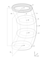
- FIG. FIG. 3 is a diagram showing an example of a three-dimensional image and cross-sectional images displayed on a display by the image processing system according to the embodiment of the present disclosure
- FIG. FIG. 4 is a diagram showing an example of a cutting area formed by the image processing system according to the embodiment of the present disclosure
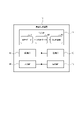
- FIG. 1 is a block diagram showing the configuration of an image processing device according to an embodiment of the present disclosure
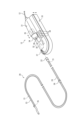
- FIG. 2 is a perspective view of a probe and drive unit according to an embodiment of the present disclosure
- 4 is a flow chart showing the operation of the image processing system according to the embodiment of the present disclosure
- 4 is a flow chart showing the operation of the image processing system according to the embodiment of the present disclosure
- FIG. 2 illustrates an example of a selection method used by an image processing system according to embodiments of the present disclosure
- FIG. 2 illustrates an example of a selection method used by an image processing system according to embodiments of the present disclosure
- FIG. 5 is a diagram showing an example of a determination technique used by an image processing system according to an embodiment of the present disclosure
- FIG. FIG. 5 is a diagram showing an example of a determination technique used by an image processing system according to an embodiment of the present disclosure
- FIG. 5 is a diagram showing an example of a determination technique used by an image processing system according to an embodiment of the present disclosure
- FIG. 1 An outline of the present embodiment will be described with reference to FIGS. 1 to 4.
- FIG. 1 An outline of the present embodiment will be described with reference to FIGS. 1 to 4.
- the image processing apparatus 11 is a computer that causes the display 16 to display at least one cross-sectional image included in the tomographic data 51, which is a data set obtained using a sensor that moves in the lumen 61 of the biological tissue 60. is. That is, the image processing device 11 causes the display 16 to display at least one cross-sectional image obtained using the sensor. Specifically, the image processing device 11 causes the display 16 to display a cross-sectional image 54 representing a cross-section 64 of the biological tissue 60 perpendicular to the moving direction of the sensor.
- the image processing device 11 When the image processing device 11 receives the input of the cross-sectional image 54 , the deformed spot 69 deformed by pressing the catheter 63 inserted into the lumen 61 on the inner surface 65 of the biological tissue 60 is displayed on the cross-sectional image 54 . determine whether it is contained in When the image processing device 11 determines that the deformed spot 69 is included in the cross-sectional image 54 , the position of the catheter 63 is specified based on the position of the deformed spot 69 .
- the image processing device 11 determines whether or not the catheter 63 is included in the cross-sectional image 54 upon receiving the input of the cross-sectional image 54 .
- the image processing device 11 determines whether the deformed spot 69 is included in the cross-sectional image 54 when it determines that the catheter 63 is not included in the cross-sectional image 54 .
- the image processing device 11 may determine whether the deformed spot 69 is included in the cross-sectional image 54 regardless of whether the catheter 63 is included in the cross-sectional image 54. .
- the image processing device 11 determines that the catheter 63 is not included in the cross-sectional image 54 and that the deformed spot 69 is included in the cross-sectional image 54, the position of the deformed spot 69 in the cross-sectional image 54 is , the position of the catheter 63 in the three-dimensional space is specified. Then, the image processing device 11 causes the display 16 to display a three-dimensional object group including an object representing the living tissue 60 in the three-dimensional space and an object representing the catheter 63 in the three-dimensional space.
- the image processing device 11 determines that the catheter 63 is included in the cross-sectional image 54
- the position of the catheter 63 in the three-dimensional space is determined based on the position of the catheter 63 in the cross-sectional image 54. Identify. Then, the image processing device 11 causes the display 16 to display a three-dimensional object group including an object representing the living tissue 60 in the three-dimensional space and an object representing the catheter 63 in the three-dimensional space.
- the deformed spot 69 is a tent-like stretched portion when the catheter 63 is pressed against the fossa ovalis 68 during the atrial septal puncture operation and the fossa ovalis 68 stretches like a tent. That is, it is a tenting spot.
- the image processing device 11 causes the display 16 to display a mark Mt indicating the position of the tenting spot in the cross-sectional image 54 .
- the mark Mt may be a mark of any color and shape, but is a solid yellow triangle in the example of FIG.
- the mark Mt is oriented in the ultrasonic radiation direction from the center of gravity Pb of the cross section 64 of the biological tissue 60 into which the catheter 63, which is an elongated medical device, is inserted.
- the tenting spots are basically displayed continuously for several frames.
- the position of the tip 67 of the catheter 63 embedded in the tissue is specified by determining the tenting spot based on information indicating the position of the catheter 63 last detected in time series or in the Z-axis direction by the image processing device 11. be able to.
- the tenting spot is determined based on the information indicating the position of the tenting spot specified in the latest frame or the previous frame.
- the position of the distal end 67 of the catheter 63 embedded in the tissue can also be specified.
- a catheter object connected to the tenting spot may be displayed on the cross-sectional image 54.
- FIG. the color tone of the catheter object is changed according to the distance in the Z-axis direction from the cross-sectional image 54, and the orientation of the triangle of the mark Mt is changed to the connection point of the catheter object connected to the tenting spot. to the tenting spot. In that case, it is easier for the user to recognize that the mark Mt is the tip object representing the tip 67 of the catheter 63 causing tenting.
- the center of the tenting spot i.e., the center of the tenting spot in three-dimensional space, is visualized in two dimensions by fading the color according to the distance in the Z-axis direction from the apex of the conically recessed tissue. good too.
- the center of the tenting spot is, for example, the radially furthest position from the center of the cross-sectional image 54 or the center of gravity Pb of the cross-section 64 in the tenting spot.
- the image processing device 11 further displays on the display 16 a mark Mc indicating the position of the catheter 63 specified in the frame in which the catheter 63 was last detected, such as the previous frame.
- the mark Mc may be a mark of any color and shape distinguishable from the mark Mt, but is a dotted red circle in the example of FIG.
- the image processing device 11 detects the tip 67 of the catheter 63, which is embedded in the tissue during tenting, in a color different from that of the catheter tube created based on the information indicating the position of the detected catheter 63. is displayed on the display 16 with .
- the position of the medical device can be identified. For example, when the operator takes an action such as pressing the catheter 63 against the fossa ovalis 68 , the catheter 63 becomes embedded in the tissue, making it difficult to detect the tip 67 of the catheter 63 from the cross-sectional image 54 .
- the tenting spot can be detected from the cross-sectional image 54, the tip 67 of the catheter 63 can be detected based on the position of the tenting spot. As a result, a three-dimensional image 53 including the tip 67 of the catheter 63 can be drawn.
- an elongated medical device other than the catheter 63 such as a guidewire or an atrial septal puncture needle, may be detected in a manner similar to this embodiment.
- the image processing device 11 generates and updates the three-dimensional data 52 representing the living tissue 60 by referring to the tomographic data 51, which is a data set obtained using a sensor.
- the image processing device 11 causes the display 16 to display the three-dimensional data 52 as a three-dimensional image 53 together with the cross-sectional image 54 . That is, the image processing apparatus 11 refers to the tomographic data 51 and causes the display 16 to display the three-dimensional image 53 and the cross-sectional image 54 .
- the image processing device 11 forms an opening 62 in the three-dimensional data 52 that exposes the lumen 61 of the biological tissue 60 in the three-dimensional image 53 .
- the opening 62 is formed so that the catheter 63, including the tip 67, and the fossa ovalis 68 are visible.
- the viewpoint for displaying the three-dimensional image 53 on the screen is adjusted according to the position of the opening 62 .
- a viewpoint is the position of a virtual camera arranged in a three-dimensional space.
- the lumen 61 of the living tissue 60 can be seen.
- the biological tissue 60 includes, for example, blood vessels or organs such as the heart.
- the biological tissue 60 is not limited to an anatomical single organ or a part thereof, but also includes a tissue that straddles a plurality of organs and has a lumen.
- a specific example of such tissue is a portion of the vascular system extending from the upper portion of the inferior vena cava through the right atrium to the lower portion of the superior vena cava.
- the living tissue 60 is a blood vessel.
- the Z direction corresponds to the moving direction of the sensor, but as shown in FIG.
- the X direction orthogonal to the Z direction and the Y direction orthogonal to the Z and X directions may be regarded as corresponding to the lateral direction of the lumen 61 of the living tissue 60 .
- the image processing device 11 uses the three-dimensional data 52 to calculate the positions of the centers of gravity B1, B2, B3 and B4 of the cross sections C1, C2, C3 and C4 of the biological tissue 60, respectively.
- the image processing apparatus 11 sets a pair of planes that intersect on a line Lb passing through the positions of the centers of gravity B1, B2, B3, and B4 as cutting planes D1 and D2.
- the image processing device 11 forms an area sandwiched between the cut planes D1 and D2 in the three-dimensional image 53 and exposing the lumen 61 of the biological tissue 60 as the cut area 66 in the three-dimensional data 52 .
- the opening 62 as shown in FIG. 2 is formed by setting the cutting area 66 to be invisible or transparent.
- FIG. 3 four cross-sections C1, C2, C3, and C4 are shown as multiple cross-sections of the biological tissue 60 orthogonal to the Z direction for convenience, but the number of cross-sections for which the position of the center of gravity is to be calculated is limited to four. and preferably equal to the number of cross-sectional images acquired by IVUS.
- the image processing system 10 includes an image processing device 11, a cable 12, a drive unit 13, a keyboard 14, a mouse 15, and a display 16.
- the image processing apparatus 11 is a dedicated computer specialized for image diagnosis in this embodiment, but may be a general-purpose computer such as a PC. "PC” is an abbreviation for personal computer.
- the cable 12 is used to connect the image processing device 11 and the drive unit 13.
- the drive unit 13 is a device that is used by connecting to the probe 20 shown in FIG.
- the drive unit 13 is also called MDU.
- MDU is an abbreviation for motor drive unit.
- Probe 20 has IVUS applications. Probe 20 is also referred to as an IVUS catheter or diagnostic imaging catheter.
- the keyboard 14, mouse 15, and display 16 are connected to the image processing device 11 via any cable or wirelessly.
- the display 16 is, for example, an LCD, organic EL display, or HMD.
- LCD is an abbreviation for liquid crystal display.
- EL is an abbreviation for electro luminescence.
- HMD is an abbreviation for head-mounted display.
- the image processing system 10 further comprises a connection terminal 17 and a cart unit 18 as options.
- connection terminal 17 is used to connect the image processing device 11 and an external device.
- the connection terminal 17 is, for example, a USB terminal.
- USB is an abbreviation for Universal Serial Bus.
- the external device is, for example, a recording medium such as a magnetic disk drive, a magneto-optical disk drive, or an optical disk drive.
- the cart unit 18 is a cart with casters for movement.
- An image processing device 11 , a cable 12 and a drive unit 13 are installed in the cart body of the cart unit 18 .
- a keyboard 14 , a mouse 15 and a display 16 are installed on the top table of the cart unit 18 .
- the probe 20 includes a drive shaft 21, a hub 22, a sheath 23, an outer tube 24, an ultrasonic transducer 25, and a relay connector 26.
- the drive shaft 21 passes through a sheath 23 inserted into the body cavity of a living body, an outer tube 24 connected to the proximal end of the sheath 23, and extends to the inside of a hub 22 provided at the proximal end of the probe 20.
- the driving shaft 21 has an ultrasonic transducer 25 for transmitting and receiving signals at its tip and is rotatably provided within the sheath 23 and the outer tube 24 .
- a relay connector 26 connects the sheath 23 and the outer tube 24 .
- the hub 22, the drive shaft 21, and the ultrasonic transducer 25 are connected to each other so as to integrally move back and forth in the axial direction. Therefore, for example, when the hub 22 is pushed toward the distal side, the drive shaft 21 and the ultrasonic transducer 25 move inside the sheath 23 toward the distal side. For example, when the hub 22 is pulled proximally, the drive shaft 21 and the ultrasonic transducer 25 move proximally inside the sheath 23 as indicated by the arrows.
- the drive unit 13 includes a scanner unit 31, a slide unit 32, and a bottom cover 33.
- the scanner unit 31 is also called a pullback unit.
- the scanner unit 31 is connected to the image processing device 11 via the cable 12 .
- the scanner unit 31 includes a probe connection section 34 that connects to the probe 20 and a scanner motor 35 that is a drive source that rotates the drive shaft 21 .
- the probe connecting portion 34 is detachably connected to the probe 20 through an insertion port 36 of the hub 22 provided at the proximal end of the probe 20 .
- the proximal end of the drive shaft 21 is rotatably supported, and the rotational force of the scanner motor 35 is transmitted to the drive shaft 21 .
- Signals are also transmitted and received between the drive shaft 21 and the image processing device 11 via the cable 12 .
- the image processing device 11 generates a tomographic image of the body lumen and performs image processing based on the signal transmitted from the drive shaft 21 .
- the slide unit 32 mounts the scanner unit 31 so as to move back and forth, and is mechanically and electrically connected to the scanner unit 31 .
- the slide unit 32 includes a probe clamp section 37 , a slide motor 38 and a switch group 39 .
- the probe clamping part 37 is arranged coaxially with the probe connecting part 34 on the tip side of the probe connecting part 34 and supports the probe 20 connected to the probe connecting part 34 .
- the slide motor 38 is a driving source that generates axial driving force.
- the scanner unit 31 advances and retreats by driving the slide motor 38, and the drive shaft 21 advances and retreats in the axial direction accordingly.
- the slide motor 38 is, for example, a servomotor.
- the switch group 39 includes, for example, a forward switch and a pullback switch that are pressed when moving the scanner unit 31 back and forth, and a scan switch that is pressed when image rendering is started and ended.
- Various switches are included in the switch group 39 as needed, without being limited to the example here.
- the scanner motor 35 When the scan switch is pressed, image rendering is started, the scanner motor 35 is driven, and the slide motor 38 is driven to move the scanner unit 31 backward.
- a user such as an operator connects the probe 20 to the scanner unit 31 in advance, and causes the drive shaft 21 to rotate and move to the proximal end side in the axial direction when image rendering is started.
- the scanner motor 35 and the slide motor 38 are stopped when the scan switch is pressed again, and image rendering is completed.
- the bottom cover 33 covers the bottom surface of the slide unit 32 and the entire circumference of the side surface on the bottom surface side, and can move toward and away from the bottom surface of the slide unit 32 .
- the image processing device 11 includes a control section 41 , a storage section 42 , a communication section 43 , an input section 44 and an output section 45 .
- the control unit 41 includes at least one processor, at least one programmable circuit, at least one dedicated circuit, or any combination thereof.
- a processor may be a general-purpose processor such as a CPU or GPU, or a dedicated processor specialized for a particular process.
- CPU is an abbreviation for central processing unit.
- GPU is an abbreviation for graphics processing unit.
- a programmable circuit is, for example, an FPGA.
- FPGA is an abbreviation for field-programmable gate array.
- a dedicated circuit is, for example, an ASIC.
- ASIC is an abbreviation for application specific integrated circuit.
- the control unit 41 executes processing related to the operation of the image processing device 11 while controlling each unit of the image processing system 10 including the image processing device 11 .
- the storage unit 42 includes at least one semiconductor memory, at least one magnetic memory, at least one optical memory, or any combination thereof.
- a semiconductor memory is, for example, a RAM or a ROM.
- RAM is an abbreviation for random access memory.
- ROM is an abbreviation for read only memory.
- RAM is, for example, SRAM or DRAM.
- SRAM is an abbreviation for static random access memory.
- DRAM is an abbreviation for dynamic random access memory.
- ROM is, for example, EEPROM.
- EEPROM is an abbreviation for electrically erasable programmable read only memory.
- the storage unit 42 functions, for example, as a main memory device, an auxiliary memory device, or a cache memory.
- the storage unit 42 stores data used for the operation of the image processing apparatus 11, such as the tomographic data 51, and data obtained by the operation of the image processing apparatus 11, such as the three-dimensional data 52 and the three-dimensional image 53. .
- the communication unit 43 includes at least one communication interface.
- the communication interface is, for example, a wired LAN interface, a wireless LAN interface, or an image diagnosis interface that receives and A/D converts IVUS signals.
- LAN is an abbreviation for local area network.
- A/D is an abbreviation for analog to digital.
- the communication unit 43 receives data used for the operation of the image processing device 11 and transmits data obtained by the operation of the image processing device 11 .
- the drive unit 13 is connected to an image diagnosis interface included in the communication section 43 .
- the input unit 44 includes at least one input interface.
- the input interface is, for example, a USB interface, an HDMI (registered trademark) interface, or an interface compatible with a short-range wireless communication standard such as Bluetooth (registered trademark).
- HDMI registered trademark
- HDMI registered trademark
- HDMI registered trademark
- HDMI registered trademark
- HDMI registered trademark
- HDMI registered trademark
- HDMI registered trademark
- the output unit 45 includes at least one output interface.
- the output interface is, for example, a USB interface, an HDMI (registered trademark) interface, or an interface compatible with a short-range wireless communication standard such as Bluetooth (registered trademark).
- the output unit 45 outputs data obtained by the operation of the image processing device 11 .
- the display 16 is connected to a USB interface or HDMI (registered trademark) interface included in the output unit 45 .
- the functions of the image processing device 11 are realized by executing the image processing program according to the present embodiment with a processor as the control unit 41 . That is, the functions of the image processing device 11 are realized by software.
- the image processing program causes the computer to function as the image processing device 11 by causing the computer to execute the operation of the image processing device 11 . That is, the computer functions as the image processing device 11 by executing the operation of the image processing device 11 according to the image processing program.
- the program can be stored on a non-transitory computer-readable medium.
- a non-transitory computer-readable medium is, for example, a flash memory, a magnetic recording device, an optical disk, a magneto-optical recording medium, or a ROM.
- Program distribution is performed, for example, by selling, assigning, or lending a portable medium such as an SD card, DVD, or CD-ROM storing the program.
- SD is an abbreviation for Secure Digital.
- DVD is an abbreviation for digital versatile disc.
- CD-ROM is an abbreviation for compact disc read only memory.
- the program may be distributed by storing the program in the storage of the server and transferring the program from the server to another computer.
- a program may be provided as a program product.
- a computer for example, temporarily stores a program stored in a portable medium or a program transferred from a server in a main storage device. Then, the computer reads the program stored in the main storage device with the processor, and executes processing according to the read program with the processor.
- the computer may read the program directly from the portable medium and execute processing according to the program.
- the computer may execute processing according to the received program every time the program is transferred from the server to the computer.
- the processing may be executed by a so-called ASP type service that realizes the function only by executing the execution instruction and obtaining the result without transferring the program from the server to the computer.
- "ASP" is an abbreviation for application service provider.
- the program includes information to be used for processing by a computer and conforming to the program. For example, data that is not a direct instruction to a computer but that has the property of prescribing the processing of the computer corresponds to "things equivalent to a program.”
- a part or all of the functions of the image processing device 11 may be realized by a programmable circuit or a dedicated circuit as the control unit 41. That is, part or all of the functions of the image processing device 11 may be realized by hardware.
- the operation of the image processing system 10 according to this embodiment will be described with reference to FIG.
- the operation of the image processing system 10 corresponds to the image processing method according to this embodiment.
- the probe 20 is primed by the user before the flow of FIG. 6 starts. After that, the probe 20 is fitted into the probe connection portion 34 and the probe clamp portion 37 of the drive unit 13 and connected and fixed to the drive unit 13 . Then, the probe 20 is inserted to a target site in a living tissue 60 such as a blood vessel or heart.
- a living tissue 60 such as a blood vessel or heart.
- step S101 the scan switch included in the switch group 39 is pressed, and the pullback switch included in the switch group 39 is pressed, so that a so-called pullback operation is performed.
- the probe 20 transmits ultrasonic waves by means of the ultrasonic transducer 25 retracted in the axial direction by a pullback operation inside the biological tissue 60 .
- the ultrasonic transducer 25 radially transmits ultrasonic waves while moving inside the living tissue 60 .
- the ultrasonic transducer 25 receives reflected waves of the transmitted ultrasonic waves.
- the probe 20 inputs the signal of the reflected wave received by the ultrasonic transducer 25 to the image processing device 11 .
- the control unit 41 of the image processing apparatus 11 processes the input signal to sequentially generate cross-sectional images of the biological tissue 60, thereby acquiring tomographic data 51 including a plurality of cross-sectional images.
- the probe 20 rotates the ultrasonic transducer 25 in the circumferential direction inside the living tissue 60 and moves it in the axial direction, and rotates the ultrasonic transducer 25 toward the outside from the center of rotation.
- the probe 20 receives reflected waves from reflecting objects present in each of a plurality of directions inside the living tissue 60 by the ultrasonic transducer 25 .
- the probe 20 transmits the received reflected wave signal to the image processing device 11 via the drive unit 13 and the cable 12 .
- the communication unit 43 of the image processing device 11 receives the signal transmitted from the probe 20 .
- the communication unit 43 A/D converts the received signal.
- the communication unit 43 inputs the A/D converted signal to the control unit 41 .
- the control unit 41 processes the input signal and calculates the intensity value distribution of the reflected waves from the reflectors present in the transmission direction of the ultrasonic waves from the ultrasonic transducer 25 .
- the control unit 41 sequentially generates two-dimensional images having a luminance value distribution corresponding to the calculated intensity value distribution as cross-sectional images of the biological tissue 60, thereby acquiring tomographic data 51, which is a data set of cross-sectional images.
- the control unit 41 causes the storage unit 42 to store the obtained tomographic data 51 .
- the signal of the reflected wave received by the ultrasonic transducer 25 corresponds to the raw data of the tomographic data 51
- the cross-sectional image generated by processing the signal of the reflected wave by the image processing device 11 is the tomographic data. 51 processing data.
- the control unit 41 of the image processing device 11 may store the signal input from the probe 20 as the tomographic data 51 in the storage unit 42 as it is.
- the control unit 41 may store, as the tomographic data 51 , data indicating the intensity value distribution of the reflected wave calculated by processing the signal input from the probe 20 in the storage unit 42 .
- the tomographic data 51 is not limited to a data set of cross-sectional images of the living tissue 60, and may be data representing cross-sections of the living tissue 60 at each movement position of the ultrasonic transducer 25 in some format.
- an ultrasonic transducer that transmits ultrasonic waves in multiple directions without rotating is used instead of the ultrasonic transducer 25 that transmits ultrasonic waves in multiple directions while rotating in the circumferential direction.
- the tomographic data 51 may be acquired using OFDI or OCT instead of being acquired using IVUS.
- OFDI is an abbreviation for optical frequency domain imaging.
- OCT is an abbreviation for optical coherence tomography.
- another device instead of the image processing device 11 generating a dataset of cross-sectional images of the biological tissue 60, another device generates a similar dataset, and the image processing device 11 generates the dataset. It may be obtained from the other device. That is, instead of the control unit 41 of the image processing device 11 processing the IVUS signal to generate a cross-sectional image of the biological tissue 60, another device processes the IVUS signal to generate a cross-sectional image of the biological tissue 60. You may generate
- step S102 the control unit 41 of the image processing apparatus 11 generates three-dimensional data 52 of the biological tissue 60 based on the tomographic data 51 acquired in step S101. That is, the control unit 41 generates the three-dimensional data 52 based on the tomographic data 51 acquired by the sensor.
- the generated three-dimensional data 52 already exists, it is possible to update only the data at the location corresponding to the updated tomographic data 51 instead of regenerating all the three-dimensional data 52 from scratch. preferable. In that case, the amount of data processing when generating the three-dimensional data 52 can be reduced, and the real-time performance of the three-dimensional image 53 in the subsequent step S103 can be improved.
- control unit 41 of the image processing device 11 stacks the cross-sectional images of the living tissue 60 included in the tomographic data 51 stored in the storage unit 42 to three-dimensionalize the living tissue 60 .
- Dimensional data 52 is generated.
- any one of rendering methods such as surface rendering or volume rendering, and associated processing such as texture mapping including environment mapping, bump mapping, and the like is used.
- the control unit 41 causes the storage unit 42 to store the generated three-dimensional data 52 .
- the tomographic data 51 includes data of the catheter 63 in the same manner as the data of the living tissue 60. Therefore, in step S ⁇ b>102 , the three-dimensional data 52 generated by the control unit 41 also includes data on the catheter 63 as well as data on the living tissue 60 .
- the control unit 41 of the image processing apparatus 11 classifies the pixel groups of the cross-sectional image included in the tomographic data 51 acquired in step S101 into two or more classes. These two or more classes include at least a "tissue” class to which the biological tissue 60 belongs, and a “catheter” class to which the catheter 63 belongs.
- a class of "medical devices”, a class of "indwelling objects” such as indwelling stents, or a class of "lesions” such as lime or plaque may also be included. Any method may be used as the classification method, but in this embodiment, a method of classifying pixel groups of cross-sectional images using a trained model is used.
- the learned model is trained by performing machine learning in advance so that it can detect regions corresponding to each class from a sample IVUS cross-sectional image.
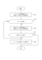
- step S102 The procedure of the processing further executed in step S102 will be described with reference to FIG. This procedure is executed each time a cross-sectional image Img(t) obtained at time t using a sensor is input.
- the control unit 41 of the image processing device 11 determines in step S201 whether the catheter 63 is included in the cross-sectional image Img(t). Specifically, the control unit 41 determines whether or not there is a pixel classified into the class “catheter” in the pixel group of the cross-sectional image Img(t). t).
- the control unit 41 of the image processing device 11 determines that the catheter 63 is included in the cross-sectional image Img(t), that is, when the catheter 63 is detected from the cross-sectional image Img(t), in step S202 , the position Cat(t) of the catheter 63 in the three-dimensional space is specified based on the position of the catheter 63 in the cross-sectional image Img(t). Specifically, the control unit 41 calculates the three-dimensional coordinates corresponding to the pixels classified into the “catheter” class as the position Cat(t) of the catheter 63 . Then, the control unit 41 stores the position Cat(t) of the catheter 63 in the storage unit 42 in step S205. Specifically, the control unit 41 adds data indicating the position Cat(t) of the catheter 63 to the three-dimensional data 52 stored in the storage unit 42 as data of the catheter 63 .
- step S203 the control unit 41 determines that the cross-sectional image Img(t) includes a deformed spot 69 deformed by pressing the catheter 63 inserted into the lumen 61 of the inner surface 65 of the biological tissue 60. determine whether or not Specifically, the control unit 41 selects at least one pixel Ps from the pixel group of the cross-sectional image Img(t), and determines whether the selected pixel Ps corresponds to the deformed spot 69. , determines whether the deformed spot 69 is included in the cross-sectional image Img(t).
- step In S204 the position Cat(t) of the catheter 63 in the three-dimensional space is specified based on the position of the deformed spot 69 in the cross-sectional image Img(t). Specifically, the control unit 41 calculates the three-dimensional coordinates corresponding to the pixel determined to correspond to the deformed spot 69 in step S ⁇ b>203 as the position Cat(t) of the catheter 63 . Then, the control unit 41 stores the position Cat(t) of the catheter 63 in the storage unit 42 in step S205. Specifically, the control unit 41 adds data indicating the position Cat(t) of the catheter 63 to the three-dimensional data 52 stored in the storage unit 42 as data of the catheter 63 .
- any one of the following first to third methods can be used.
- the first method is a rule-based corner selection method.
- the first method includes the following steps. 1. For each pixel of the cross-sectional image Img(t), a group of pixels existing on a circle with a constant distance from the target pixel Pt is extracted. FIG. 8 shows an example where the distance is 3 pixels. 2. It is determined whether each pixel is similar to the target pixel Pt. For example, it is determined whether each pixel is as black or white as the target pixel Pt. 3. As a result of the determination, it is determined whether pixels considered to be similar continuously occupy 45 degrees to 135 degrees of the circumference. That is, a fan-shaped area of 45 degrees or more and 135 degrees or less is detected.
- the lower limit of the angle range is not limited to 45 degrees, and may be any value greater than 0 degrees.
- the upper limit of the angle range is not limited to 135 degrees, and may be any value smaller than 180 degrees. 4.
- the target pixel Pt is regarded as a corner. That is, the target pixel Pt is selected as the pixel Ps. A pixel adjacent to the target pixel Pt may be further selected as the pixel Ps.
- the control unit 41 of the image processing apparatus 11 targets each pixel of the cross-sectional image Img(t), and for each pixel present on the circumference where the distance from the target pixel Pt is constant, , the similarity with the target pixel Pt is calculated.
- the degree of similarity is calculated by comparing the characteristics of each pixel, such as the brightness of each pixel or the class to which each pixel is classified.
- the control unit 41 selects the target pixel Pt as the pixel Ps when the angle at which the pixels having the calculated degree of similarity equal to or greater than the reference value are continuously present on the circumference is within the reference range.
- the reference value is preset to an arbitrary value and adjusted as appropriate.
- the reference range may be an arbitrary range larger than 0 degrees and smaller than 180 degrees, but is preset to a range of 45 degrees or more and 135 degrees or less, for example.
- the target pixel Pt is selected as the pixel Ps.
- the second method is also a method of selecting corners based on rules.
- the second method includes the following steps. 1. A boundary line of a region corresponding to the lumen 61 of the cross-sectional image Img(t) is extracted. 2. Each pixel on the boundary line is targeted, and the target pixel Pt is set as a starting point. 3. A fixed number of nearest neighbor points existing on the boundary line in the counterclockwise direction from the starting point are extracted and set as a point group P1. FIG. 9 shows an example of extracting 5 points. 4. A fixed number of nearest neighbor points existing on the boundary line in the clockwise direction from the starting point are extracted and set as a point group P2. FIG. 9 shows an example of extracting 5 points. 5.
- a regression line L1 and a regression line L2 are drawn for the point group P1 and the point group P2, respectively. 6. It is determined whether the smaller angle between the regression line L1 and the regression line L2 is 30 degrees or more and 75 degrees or less. That is, a substantially V-shaped boundary line of 30 degrees or more and 75 degrees or less is detected.
- the lower limit of the angle range is not limited to 30 degrees, and may be any value greater than 0 degrees.
- the upper limit of the angle range is not limited to 75 degrees, and may be any value smaller than 90 degrees.
- the target pixel Pt is regarded as a corner. That is, the target pixel Pt is selected as the pixel Ps. Pixels included in the point group P1 and the point group P2 may be further selected as pixels Ps.
- the control unit 41 of the image processing device 11 targets each pixel on the boundary line corresponding to the inner surface 65 of the biological tissue 60 among the pixel groups of the cross-sectional image Img(t), A first pixel group existing on one side of the target pixel Pt on the boundary line and a second pixel group existing on the other side of the target pixel Pt on the boundary line are extracted.
- the first pixel group corresponds to point group P1.
- the second pixel group corresponds to point group P2.
- the control unit 41 determines whether the target pixel Pt is selected as the pixel Ps.
- the reference range may be any range greater than 0 degrees and less than 90 degrees, but is preset to a range of 30 degrees or more and 75 degrees or less, for example.
- a regression line L1 corresponding to the first pixel group existing on one side of the target pixel Pt on the boundary line and a regression line L1 corresponding to the second pixel group existing on the other side of the target pixel Pt on the boundary line Assume that the angle formed with the straight line L2 is 30 degrees or more and 75 degrees or less. In this case, the target pixel Pt is selected as the pixel Ps.
- a third method is to select corners with a neural network.
- a third method includes the following steps. 1.
- a machine-learning algorithm Am that determines whether there is a tenting spot is created in advance using at least an ultrasound image as input. 2. With an ultrasound image of interest as an input, algorithm Am determines whether there is a tenting spot. 3. If it is determined that there is a tenting spot, Grad-CAM is used, for example, to extract the area emphasized by the algorithm Am. "Grad-CAM" is an abbreviation for gradient-weighted class activation mapping. 4. The center pixel of the area emphasized by algorithm Am is regarded as the corner. That is, the center pixel is selected as the pixel Ps. Pixels within a certain area including the center may also be selected as pixels Ps.
- the control unit 41 of the image processing device 11 receives an image obtained using a sensor as an input, and uses it as a learned model for inferring pixels corresponding to the deformed spot 69 in the input image.
- a cross-sectional image Img(t) is input.
- a trained model is created in advance by, for example, deep learning.
- the control unit 41 selects the inferred pixel as the pixel Ps.
- the following first method or second method can be used.
- a first method is a method of determining whether or not a corner is a tenting spot based on past catheter information using an orthogonal coordinate system.
- a first approach includes the following steps. 1. Information indicating the position Pc of the catheter 63 in the cross-sectional image Img(u) obtained at the time u when the catheter 63 was last detected is referred to. Time u is, for example, time t ⁇ 1. If the cross-section represented by the cross-sectional image Img(u) and the cross-section 64 represented by the cross-sectional image Img(t) are separated by a certain distance or more in the Z direction, the catheter detected before the time u Information indicating the position of 63 may be referred to instead. 2.
- a line Lt connecting a point Pa regarded as a corner and the center of gravity Pb of the cross section 64 or the center of the cross section image Img(t) is drawn. 3.
- a line Lc connecting the position Pc and the center of gravity Pb of the cross section 64 or the center of the cross section image Img(t) is drawn. 4. It is determined whether or not the smaller angle between the line Lt and the line Lc is 30 degrees or less. If the angle is 30 degrees or less, the point Pa is determined to be a tenting spot.
- the angle threshold is not limited to 30 degrees, and may be any value smaller than 45 degrees.
- the control unit 41 of the image processing device 11 selects the pixel Ps and the catheter 63 in the cross-sectional image Img(u) including the catheter 63, which is different from the cross-sectional image Img(t). , it is determined whether the selected pixel Ps corresponds to the deformed spot 69 or not.
- the position indicated by the mark Mc corresponds to the position Pc of the catheter 63 in the cross-sectional image Img(u).
- the position indicated by the mark Mt corresponds to the position of the pixel Ps when it is determined that the pixel Ps corresponds to the tenting spot, that is, the point Pa. This means that the angle between the line Lt connecting the mark Mt and the center of gravity Pb and the line Lc connecting the mark Mc and the center of gravity Pb is 30 degrees or less.
- the first method may be a method of determining whether or not the corner is a tenting spot based on catheter information at a time after time t, using an orthogonal coordinate system. For example, when the catheter 63 is not detected at time t and a corner portion that is a tenting spot candidate is obtained, if the catheter 63 is detected at time t+1, the corner is detected by the same method retroactively to time t. It may be determined whether a part is a tenting spot.
- a first method may be a method of determining whether or not the corner is a tenting spot based on past catheter information in a polar coordinate system.
- the first approach includes the following steps. 1. Information indicating the position Pc of the catheter 63 in the cross-sectional image Img(u) obtained at the time u when the catheter 63 was last detected is referred to. 2. The position Pc is compared with the point Pa regarded as the corner, and it is determined whether the absolute value of the difference in angle components is 30 degrees or less. If the absolute value of the angle component difference is 30 degrees or less, the point Pa is determined to be a tenting spot.
- the angle threshold is not limited to 30 degrees, and may be any value smaller than 45 degrees.
- a second technique is to determine whether a corner is a tenting spot based on the continuity of the tenting spots.
- a second approach includes the following steps. 1. It is determined whether there is a point regarded as a corner in the cross-sectional image Img(t-1) and a point regarded as a corner in the cross-sectional image Img(t-2) within 3 mm around the point Pa regarded as the corner. .
- the peripheral distance is not limited to 3 mm, and may be approximately 4 mm or approximately 5 mm. Peripheral distances may be replaced by radius distances or angular differences. Instead of determining whether there is a corner in three frames continuously, it may be determined whether there is a corner in two frames in succession, or in four or more frames in succession.
- the control unit 41 of the image processing device 11 selects at least one pixel Ps from pixel groups of each of two or more cross-sectional images obtained continuously using the sensor. do.
- the control unit 41 determines whether the selected pixel Ps corresponds to the deformed spot 69 according to the positional difference of the selected pixel Ps between the two or more cross-sectional images.
- the second technique may be combined with the first technique.
- the second approach includes the following steps. 1. 3 mm around the point Pa regarded as a tenting spot in the first method, a point regarded as a tenting spot in the cross-sectional image Img (t-1), and a tenting spot in the cross-sectional image Img (t-2) Determine if there is a point.
- the peripheral distance is not limited to 3 mm, and may be approximately 4 mm or approximately 5 mm. Peripheral distances may be replaced by radius distances or angular differences. Instead of determining whether there is a tenting spot in 3 consecutive frames, it may be determined whether there is a tenting spot in 2 consecutive frames, or 4 or more frames in succession.
- the point Pa is It is judged to be a tenting spot.
- a method of determining whether or not a corner is a tenting spot based on past catheter information is adopted using an orthogonal coordinate system. , the accuracy of tenting spot detection can be greatly improved.
- the peripheral edge of the group of pixels classified into the "blood cell" class is used as the boundary, and several corners are detected from the boundary. Some of the corners are excluded by applying the first method.
- the second method if there is a tenting spot, the position of the tenting spot is specified, and if there is no tenting spot, it is determined that there is no tenting spot. .
- a method of determining whether a corner is a tenting spot based on past catheter information in a polar coordinate system is adopted. As shown, the accuracy of tenting spot detection can be greatly improved.
- the peripheral edge of the group of pixels classified into the "blood cell" class is used as the boundary, and several corners are detected from the boundary. One or two of the several corners are excluded by applying the first technique. Then, by further applying the second method, if there is a tenting spot, the position of the tenting spot is specified, and if there is no tenting spot, it is determined that there is no tenting spot. .
- the control unit 41 of the image processing device 11 detects corners at the same position or close to each other continuously for a certain distance such as 10 mm in the Z direction. You may determine that it is not a spot. Alternatively, when a corner is detected at the same position or a close position continuously for a certain period of time such as several seconds, the control unit 41 may determine that the corner is not a tenting spot.
- the control unit 41 of the image processing device 11 determines whether or not the deformed spot 69 is included in the cross-sectional image Img(t) without selecting the pixel Ps in step S203.
- the control unit 41 receives an image obtained using a sensor as an input, and inserts a cross-sectional image Img(t) into a trained model that infers whether or not the input image contains the deformed spot 69. Enter The control unit 41 determines whether or not the deformed spot 69 is included in the cross-sectional image Img(t) by referring to the obtained inference result.
- the same machine learning algorithm Am as the third method may be created in advance.
- algorithm Am determines whether there is a tenting spot. If it is determined that there is a tenting spot, Grad-CAM is used to extract the area emphasized by the algorithm Am. Pixels in the center of the area emphasized by algorithm Am are considered tenting spots.
- control unit 41 of the image processing device 11 receives an image obtained using a sensor as an input, and a learned model that infers data indicating the position of the deformation spot 69 in the input image. may be input with the cross-sectional image Img(t).
- the control unit 41 determines whether or not the deformed spot 69 is included in the cross-sectional image Img(t) by referring to the obtained inference result. For example, data indicating the position of the tenting spot may be included in the teacher data when the machine learning algorithm Am is created.
- step S103 the control unit 41 of the image processing device 11 causes the display 16 to display the three-dimensional data 52 generated in step S102 as a three-dimensional image 53.
- the control unit 41 may set the angle at which the three-dimensional image 53 is displayed to any angle.
- the control unit 41 causes the display 16 to display the latest cross-sectional image 54 included in the tomographic data 51 acquired in step S101 together with the three-dimensional image 53 .
- the control unit 41 of the image processing device 11 generates a 3D image 53 from the 3D data 52 stored in the storage unit 42 .
- the three-dimensional image 53 includes a three-dimensional object group such as an object representing the living tissue 60 in three-dimensional space and an object representing the catheter 63 in the three-dimensional space. That is, the control unit 41 generates a three-dimensional object of the living tissue 60 from the data of the living tissue 60 stored in the storage unit 42, and creates a three-dimensional object of the catheter 63 from the data of the catheter 63 stored in the storage unit 42. Generate.
- the control unit 41 displays the latest cross-sectional image 54 among the cross-sectional images of the biological tissue 60 included in the tomographic data 51 stored in the storage unit 42 and the generated three-dimensional image 53 via the output unit 45. 16.
- step S104 if there is an operation to set the angle for displaying the three-dimensional image 53 as the user's change operation, the process of step S105 is executed. If there is no change operation by the user, the process of step S106 is executed.
- step S ⁇ b>105 the control unit 41 of the image processing device 11 receives an operation via the input unit 44 to set the angle for displaying the three-dimensional image 53 .
- the control unit 41 adjusts the angle at which the three-dimensional image 53 is displayed to the set angle.
- step S103 the control unit 41 causes the display 16 to display the three-dimensional image 53 at the angle set in step S105.
- control unit 41 of the image processing device 11 allows the user to manipulate the three-dimensional image 53 displayed on the display 16 using the keyboard 14, the mouse 15, or the touch screen provided integrally with the display 16.
- An operation to rotate is received via the input unit 44 .
- the control unit 41 interactively adjusts the angle at which the three-dimensional image 53 is displayed on the display 16 according to the user's operation.
- the control unit 41 causes the input unit 44 to input the numerical value of the angle for displaying the three-dimensional image 53 by the user using the keyboard 14, the mouse 15, or the touch screen provided integrally with the display 16. accepted through The control unit 41 adjusts the angle at which the three-dimensional image 53 is displayed on the display 16 according to the input numerical value.
- step S106 if the tomographic data 51 is updated, the processes of steps S107 and S108 are executed. If the tomographic data 51 has not been updated, in step S104, it is confirmed again whether or not the user has performed a change operation.
- step S107 the control unit 41 of the image processing device 11 processes the signal input from the probe 20 to newly generate a cross-sectional image 54 of the biological tissue 60, similarly to the processing of step S101.
- Tomographic data 51 including two new cross-sectional images 54 are acquired.
- step S108 the control unit 41 of the image processing apparatus 11 updates the three-dimensional data 52 of the living tissue 60 based on the tomographic data 51 acquired at step S107. That is, the control unit 41 updates the three-dimensional data 52 based on the tomographic data 51 acquired by the sensor.
- step S108 the operation of FIG. 7 is also performed. The procedure shown in FIG. 7 is executed each time a cross-sectional image Img(t) obtained at time t using a sensor is input. Then, in step S103, the control unit 41 causes the display 16 to display the three-dimensional data 52 updated in step S108 as the three-dimensional image 53.
- the control unit 41 causes the display 16 to display the latest cross-sectional image 54 included in the tomographic data 51 acquired in step S ⁇ b>107 together with the three-dimensional image 53 .
- step S108 it is preferable to update only the data corresponding to the updated tomographic data 51. FIG. In that case, the amount of data processing when generating the three-dimensional data 52 can be reduced, and the real-time performance of the three-dimensional image 53 can be improved in step S108.
- the control unit 41 of the image processing device 11 receives an input of at least one cross-sectional image obtained using a sensor that moves in the lumen 61 of the biological tissue 60, the biological tissue It is determined whether or not the at least one cross-sectional image includes a deformed spot 69 on the inner surface 65 of the body 60 that has been deformed by being pressed against the catheter 63 inserted into the lumen 61 .
- the controller 41 identifies the position of the catheter 63 based on the position of the deformed spot 69 .
- an AI can be built to identify tenting spots by detecting depressions in tenting spots.
- AI is an abbreviation for artificial intelligence.
Landscapes
- Health & Medical Sciences (AREA)
- Engineering & Computer Science (AREA)
- Life Sciences & Earth Sciences (AREA)
- General Health & Medical Sciences (AREA)
- Medical Informatics (AREA)
- Nuclear Medicine, Radiotherapy & Molecular Imaging (AREA)
- Public Health (AREA)
- Surgery (AREA)
- Radiology & Medical Imaging (AREA)
- Biomedical Technology (AREA)
- Physics & Mathematics (AREA)
- Heart & Thoracic Surgery (AREA)
- Veterinary Medicine (AREA)
- Molecular Biology (AREA)
- Animal Behavior & Ethology (AREA)
- Biophysics (AREA)
- Pathology (AREA)
- Computer Vision & Pattern Recognition (AREA)
- Theoretical Computer Science (AREA)
- General Physics & Mathematics (AREA)
- Epidemiology (AREA)
- Primary Health Care (AREA)
- Robotics (AREA)
- Quality & Reliability (AREA)
- Ultra Sonic Daignosis Equipment (AREA)
- Image Processing (AREA)
Priority Applications (2)
| Application Number | Priority Date | Filing Date | Title |
|---|---|---|---|
| JP2023540341A JPWO2023013601A1 (https=) | 2021-08-02 | 2022-08-01 | |
| US18/428,352 US20240177834A1 (en) | 2021-08-02 | 2024-01-31 | Image processing device, image processing system, image processing method, and image processing program |
Applications Claiming Priority (2)
| Application Number | Priority Date | Filing Date | Title |
|---|---|---|---|
| JP2021126943 | 2021-08-02 | ||
| JP2021-126943 | 2021-08-02 |
Related Child Applications (1)
| Application Number | Title | Priority Date | Filing Date |
|---|---|---|---|
| US18/428,352 Continuation US20240177834A1 (en) | 2021-08-02 | 2024-01-31 | Image processing device, image processing system, image processing method, and image processing program |
Publications (2)
| Publication Number | Publication Date |
|---|---|
| WO2023013601A1 true WO2023013601A1 (ja) | 2023-02-09 |
| WO2023013601A9 WO2023013601A9 (ja) | 2023-12-21 |
Family
ID=85155565
Family Applications (1)
| Application Number | Title | Priority Date | Filing Date |
|---|---|---|---|
| PCT/JP2022/029541 Ceased WO2023013601A1 (ja) | 2021-08-02 | 2022-08-01 | 画像処理装置、画像処理システム、画像処理方法、及び画像処理プログラム |
Country Status (3)
| Country | Link |
|---|---|
| US (1) | US20240177834A1 (https=) |
| JP (1) | JPWO2023013601A1 (https=) |
| WO (1) | WO2023013601A1 (https=) |
Citations (3)
| Publication number | Priority date | Publication date | Assignee | Title |
|---|---|---|---|---|
| JP2007083038A (ja) * | 2005-09-16 | 2007-04-05 | Mediguide Ltd | 医療装置を管腔内の選択位置に搬送するための方法及びシステム |
| JP2012120843A (ja) * | 2010-12-09 | 2012-06-28 | Biosense Webster (Israel) Ltd | 接触測定を用いる臨界cfae部位の同定 |
| WO2021065750A1 (ja) * | 2019-09-30 | 2021-04-08 | テルモ株式会社 | 診断支援装置、診断支援システム、及び診断支援方法 |
-
2022
- 2022-08-01 JP JP2023540341A patent/JPWO2023013601A1/ja active Pending
- 2022-08-01 WO PCT/JP2022/029541 patent/WO2023013601A1/ja not_active Ceased
-
2024
- 2024-01-31 US US18/428,352 patent/US20240177834A1/en active Pending
Patent Citations (3)
| Publication number | Priority date | Publication date | Assignee | Title |
|---|---|---|---|---|
| JP2007083038A (ja) * | 2005-09-16 | 2007-04-05 | Mediguide Ltd | 医療装置を管腔内の選択位置に搬送するための方法及びシステム |
| JP2012120843A (ja) * | 2010-12-09 | 2012-06-28 | Biosense Webster (Israel) Ltd | 接触測定を用いる臨界cfae部位の同定 |
| WO2021065750A1 (ja) * | 2019-09-30 | 2021-04-08 | テルモ株式会社 | 診断支援装置、診断支援システム、及び診断支援方法 |
Also Published As
| Publication number | Publication date |
|---|---|
| JPWO2023013601A1 (https=) | 2023-02-09 |
| US20240177834A1 (en) | 2024-05-30 |
| WO2023013601A9 (ja) | 2023-12-21 |
Similar Documents
| Publication | Publication Date | Title |
|---|---|---|
| US20220218309A1 (en) | Diagnostic assistance device, diagnostic assistance system, and diagnostic assistance method | |
| JP7300352B2 (ja) | 診断支援装置、診断支援システム、及び診断支援方法 | |
| US20240108313A1 (en) | Image processing device, image display system, image processing method, and image processing program | |
| CN115484872B (zh) | 图像处理装置、图像处理系统、图像显示方法及图像处理程序 | |
| WO2023013601A1 (ja) | 画像処理装置、画像処理システム、画像処理方法、及び画像処理プログラム | |
| JP7821778B2 (ja) | 画像処理装置、画像処理システム、画像表示方法、及び画像処理プログラム | |
| JP7717150B2 (ja) | 画像処理装置、画像処理システム、画像表示方法、及び画像処理プログラム | |
| JP7682914B2 (ja) | 画像処理装置、画像処理システム、画像表示方法、及び画像処理プログラム | |
| JP7727545B2 (ja) | 診断支援装置、診断支援システム、及び診断支援方法 | |
| US20240242396A1 (en) | Image processing device, image processing system, image display method, and image processing program | |
| JP7585307B2 (ja) | 画像処理装置、画像処理システム、画像表示方法、及び画像処理プログラム | |
| CN114502079B (zh) | 诊断支援装置、诊断支援系统及诊断支援方法 | |
| JP7671774B2 (ja) | 画像処理装置、画像処理システム、画像表示方法、及び画像処理プログラム | |
| US20240013390A1 (en) | Image processing device, image processing system, image display method, and image processing program | |
| JP2023024072A (ja) | 画像処理装置、画像処理システム、画像表示方法、及び画像処理プログラム | |
| US20230252749A1 (en) | Image processing device, image processing system, image display method, and image processing program | |
| WO2023176741A1 (ja) | 画像処理装置、画像処理システム、画像表示方法、及び画像処理プログラム | |
| WO2024071054A1 (ja) | 画像処理装置、画像表示システム、画像表示方法、及び画像処理プログラム | |
| WO2022202203A1 (ja) | 画像処理装置、画像処理システム、画像表示方法、及び画像処理プログラム | |
| WO2021200296A1 (ja) | 画像処理装置、画像処理システム、画像表示方法、及び画像処理プログラム |
Legal Events
| Date | Code | Title | Description |
|---|---|---|---|
| 121 | Ep: the epo has been informed by wipo that ep was designated in this application |
Ref document number: 22853020 Country of ref document: EP Kind code of ref document: A1 |
|
| WWE | Wipo information: entry into national phase |
Ref document number: 2023540341 Country of ref document: JP |
|
| NENP | Non-entry into the national phase |
Ref country code: DE |
|
| 122 | Ep: pct application non-entry in european phase |
Ref document number: 22853020 Country of ref document: EP Kind code of ref document: A1 |