WO2023013159A1 - 可搬型電気機器 - Google Patents
可搬型電気機器 Download PDFInfo
- Publication number
- WO2023013159A1 WO2023013159A1 PCT/JP2022/014480 JP2022014480W WO2023013159A1 WO 2023013159 A1 WO2023013159 A1 WO 2023013159A1 JP 2022014480 W JP2022014480 W JP 2022014480W WO 2023013159 A1 WO2023013159 A1 WO 2023013159A1
- Authority
- WO
- WIPO (PCT)
- Prior art keywords
- grip
- lamp
- housing
- electric device
- wide
- Prior art date
- Legal status (The legal status is an assumption and is not a legal conclusion. Google has not performed a legal analysis and makes no representation as to the accuracy of the status listed.)
- Ceased
Links
Images









Classifications
-
- F—MECHANICAL ENGINEERING; LIGHTING; HEATING; WEAPONS; BLASTING
- F21—LIGHTING
- F21L—LIGHTING DEVICES OR SYSTEMS THEREOF, BEING PORTABLE OR SPECIALLY ADAPTED FOR TRANSPORTATION
- F21L4/00—Electric lighting devices with self-contained electric batteries or cells
-
- F—MECHANICAL ENGINEERING; LIGHTING; HEATING; WEAPONS; BLASTING
- F21—LIGHTING
- F21L—LIGHTING DEVICES OR SYSTEMS THEREOF, BEING PORTABLE OR SPECIALLY ADAPTED FOR TRANSPORTATION
- F21L4/00—Electric lighting devices with self-contained electric batteries or cells
- F21L4/02—Electric lighting devices with self-contained electric batteries or cells characterised by the provision of two or more light sources
-
- F—MECHANICAL ENGINEERING; LIGHTING; HEATING; WEAPONS; BLASTING
- F21—LIGHTING
- F21V—FUNCTIONAL FEATURES OR DETAILS OF LIGHTING DEVICES OR SYSTEMS THEREOF; STRUCTURAL COMBINATIONS OF LIGHTING DEVICES WITH OTHER ARTICLES, NOT OTHERWISE PROVIDED FOR
- F21V19/00—Fastening of light sources or lamp holders
- F21V19/02—Fastening of light sources or lamp holders with provision for adjustment, e.g. for focusing
-
- F—MECHANICAL ENGINEERING; LIGHTING; HEATING; WEAPONS; BLASTING
- F21—LIGHTING
- F21V—FUNCTIONAL FEATURES OR DETAILS OF LIGHTING DEVICES OR SYSTEMS THEREOF; STRUCTURAL COMBINATIONS OF LIGHTING DEVICES WITH OTHER ARTICLES, NOT OTHERWISE PROVIDED FOR
- F21V21/00—Supporting, suspending, or attaching arrangements for lighting devices; Hand grips
- F21V21/14—Adjustable mountings
- F21V21/30—Pivoted housings or frames
-
- F—MECHANICAL ENGINEERING; LIGHTING; HEATING; WEAPONS; BLASTING
- F21—LIGHTING
- F21Y—INDEXING SCHEME ASSOCIATED WITH SUBCLASSES F21K, F21L, F21S and F21V, RELATING TO THE FORM OR THE KIND OF THE LIGHT SOURCES OR OF THE COLOUR OF THE LIGHT EMITTED
- F21Y2105/00—Planar light sources
- F21Y2105/10—Planar light sources comprising a two-dimensional [2D] array of point-like light-generating elements
-
- F—MECHANICAL ENGINEERING; LIGHTING; HEATING; WEAPONS; BLASTING
- F21—LIGHTING
- F21Y—INDEXING SCHEME ASSOCIATED WITH SUBCLASSES F21K, F21L, F21S and F21V, RELATING TO THE FORM OR THE KIND OF THE LIGHT SOURCES OR OF THE COLOUR OF THE LIGHT EMITTED
- F21Y2115/00—Light-generating elements of semiconductor light sources
- F21Y2115/10—Light-emitting diodes [LED]
Definitions
- the present invention relates to a portable electrical device such as a portable lighting device.
- Patent Document 1 discloses a light having a first lamp (spotlight) and a second lamp (widelight).
- Patent Document 1 if the irradiation direction of the first lamp (spotlight) is to be switched, the irradiation direction of the second lamp (wide light) is also switched.
- the first problem is that the desired direction cannot be achieved and the usability is poor.
- the grip is gripped when the light is not in use, it is necessary to grip the second lamp extending in the direction of the grip together with the grip.
- An object of the present invention is to provide a portable electrical device that solves at least one of the first and second problems.
- One aspect of the present invention is a portable electrical device.
- This portable electric device includes a housing, a first lamp provided in the housing and rotatable about a first rotation axis, and a lamp provided in the housing and rotatable about a second rotation axis. and a second lamp having an irradiation angle or brightness different from that of the first lamp, wherein the first rotation shaft and the A first rotating shaft supporting portion and a second rotating shaft supporting portion for supporting the second rotating shaft are provided in the housing.
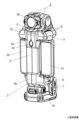
- FIG. 2 is a perspective view of the electric device 1 as seen from the front;
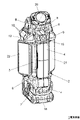
- FIG. FIG. 3 is a front perspective view of the electric device 1 in which wide lights 21 and 22 are rotated by 90° with respect to the states of FIGS. 1 and 2 ;
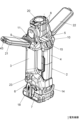
- 3 is a rear perspective view of the electric device 1 in which the spotlight 20 is rotated by 135° and the wide lights 21 and 22 are rotated by 135° with respect to the state of FIGS. 1 and 2.
- FIG. 3 is a front perspective view of the electric device 1 in which the wide lights 21 and 22 are rotated upward by 90° and rotated by 90° with respect to the states of FIGS. 1 and 2 ; 1 and 2, the spotlight 20 is rotated by 90°, and the wide lights 21 and 22 are rotated upward by 115° and rotated by 90°. figure.
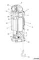
- FIG. 2 is a right side view of the electric device 1 with the front panel of the wide light 22 omitted.
- FIG. 13 is an enlarged view of a part of the EE section of FIG. 12; FIG.
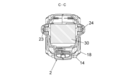
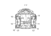
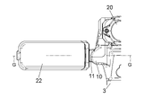
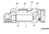
- FIG. 14 is a cross-sectional view of the entire electric device 1 taken along line FF of FIG. 14; 2 is a front view of part of the electric device 1; FIG. GG sectional view of FIG. The back view of 1 A of electric equipment which concerns on Embodiment 2 of this invention.
- the left view of the electric equipment 1A The left side view which shows that 1 A of electric equipment of the same type can be mounted with respect to 1 A of electric equipment.
- FIGS. 1 to 17 relate to an electric device 1 according to Embodiment 1 of the present invention.
- the electric device 1 is a portable lighting device (lighting fixture) called a floodlight or a work light.
- a portable lighting device lighting fixture
- FIG. 1 front and rear, up and down, and left and right directions, which are orthogonal to each other, in the electric device 1 are defined.
- the unit of each dimension illustrated in FIGS. 10, 12 and 13 is mm.
- the electric device 1 has a housing 2, a spotlight 20 as a first lamp, and wide lights 21 and 22 as second lamps.
- the housing 2 is, for example, a resin molding having a D-shaped portion when viewed in the left-right direction.
- the housing 2 includes a base 3, a grip 4, an upper connection portion 5, a lower connection portion 6, a battery holding portion 7, a first rotation support portion 8, second rotation support portions 9 and 10, and a third rotation support. Including parts 11 and 12.
- the base 3, the grip 4, the upper connecting part 5 and the lower connecting part 6 constitute a D-shaped part.
- the first lamp and the second lamp in this embodiment differ in irradiation angle or brightness.
- the base 3 extends vertically. As shown in FIG. 2, the base 3 has legs 3a and 3b and a hooking hole 3c on its front surface (the surface opposite to the grip 4).
- the leg portions 3a and 3b have front surfaces that are planes perpendicular to the front-rear direction, and serve as contact portions (contact surfaces) when the electric device 1 is placed (made independent) with the base 3 facing down.
- the hooking hole 3c can be used when hooking the electrical device 1 on the head of a screw or nail driven into the wall to such an extent that the head is not buried.
- the grip 4 extends vertically behind the base 3 (in parallel with the base 3). The grip 4 overlaps the base 3 in the left-right direction.
- the grip 4 is a portion that is gripped by the operator.
- the electric device 1 has a switch 15 at the upper end of the grip 4 .
- the switch 15 is an operation unit for the operator to switch the spotlight 20 and the wide lights 21 and 22 on and off.
- the electric device 1 has a hook 14 that can be pulled out from the rear portion of the grip 4 as shown in FIG. Using the hook 14, the electric device 1 can be hooked on a single pipe or the like.
- the upper connecting portion 5 connects the upper end portions of the base 3 and the grip 4 to each other.
- the lower connecting portion 6 connects the lower ends of the base 3 and the grip 4 to each other.
- the electrical device 1 has a USB power supply terminal 31 that can output charging power to a mobile device such as a smart phone on the front left side of the lower connection portion 6 .
- the electrical device 1 has a control board 30 inside the lower connection portion 6 .
- the control board 30 controls power supply to the spotlight 20 and the wide lights 21 and 22 according to the operation of the switch 15 .
- the battery holding portion 7 is connected to the lower end of the lower connecting portion 6 .
- the battery holding portion 7 is provided on the lower end side (one end side) of the grip 4 .
- a battery 18 (battery pack) serving as a power supply can be detachably attached to the battery holding portion 7 .
- the electrical equipment 1 is of a cordless type that operates on the power of a battery 18 attached to the battery holding portion 7 .
- the first rotation support portions 8 are provided upright on both left and right sides of the upper surface of the upper connection portion 5 .
- the first rotation support portion 8 supports the spotlight 20 so as to be rotatable around the first rotation axis L1 shown in FIGS. 9 and 13 .
- the first rotation axis L1 is an axis parallel to the left-right direction.
- the spotlight 20 is positioned on the upper end side (the other end side) of the grip 4 by being supported by the first rotation support portion 8 .
- the rotation range of the spotlight 20 is, for example, from the forward direction shown in FIG. 1 to the rear obliquely upward direction shown in FIG.
- the spotlight 20 may be rotatable to the rear (opposite direction in FIG. 1).
- a second locking pin 27 and a spring 28 are provided on the spotlight 20 side.
- concave portions (not shown) that engage with the second locking pins 27 are provided at predetermined angular intervals around the first rotation axis L1.
- the spring 28 is biasing means for biasing the second locking pin 27 toward the first rotation support portion 8 .
- the second locking pin 27 is a locking pin that is fitted into the concave portion on the side of the first turning support portion 8 by the bias of the spring 28 and locks the turning position of the spotlight 20 .
- the second rotation support portion 9 is provided to stand leftward on both front and rear sides of the left side surface of the upper connection portion 5 .
- the second rotation support portion 9 supports the wide light 21 via the third rotation support portion 11 so as to be rotatable about the second rotation axis L2 shown in FIGS. 7 and 15 .
- the second rotation axis L2 is an axis line parallel to the front-rear direction and is offset to the left with respect to the grip 4 .
- the wide light 21 is supported on the upper end side (the other end side) of the grip 4 by the second rotation support portion 9 and is positioned to the left of the grip 4 .
- the second rotation support portion 10 is erected rightward on both front and rear sides of the right side surface of the upper connection portion 5 .
- the second rotation support portion 10 supports the wide light 22 through the third rotation support portion 12 so as to be rotatable about the second rotation axis L3 shown in FIGS. 8, 15 and 17 .
- the second rotation axis L3 is an axis parallel to the front-rear direction and is offset to the right with respect to the grip 4 .
- the wide light 22 is supported on the upper end side (the other end side) of the grip 4 by the second rotation support portion 10 and is positioned on the right side of the grip 4 .
- the inner ring portion 41 and the outer ring portion 42 shown in FIG. 14 constitute a stepped rotation mechanism of the wide light 21 .
- the inner ring portion 41 is provided on the side of the third rotation support portion 11
- the outer ring portion 42 is provided on the side of the second rotation support portion 9 .
- Concavities and convexities are arranged at predetermined angular intervals on the outer peripheral surface of the inner ring portion 41 .
- a pair of protrusions 42 a that engage (fit) with the recesses of the inner ring portion 41 are provided on the inner peripheral surface of the outer ring portion 42 .
- the stepped rotation mechanism of the wide light 22 is also configured in the same manner as the stepped rotation mechanism of the wide light 21 .
- the rotation range of the wide lights 21 and 22 supported by the second rotation support portions 9 and 10 is, for example, from a state parallel to the vertical direction shown in FIG. °).
- the tips of the wide lights 21 and 22 are preferably positioned lower than the upper surface of the spotlight 20 directed upward. As a result, shadows of the wide lights 21 and 22 are suppressed from entering the irradiation range of the spotlight 20 .
- the third rotation support portion 11 is provided so as to extend between the front and rear second rotation support portions 9 .
- the third rotation support portion 11 is a member interposed between the second rotation support portion 9 and the wide light 21 to connect them.
- the third rotation support portion 11 supports the wide light 21 so as to be steplessly rotatable (rotating) around the third rotation axis L4 shown in FIG.
- the third rotation axis L4 is an axis line perpendicular to the second rotation axis L2 shown in FIGS.
- the third rotation support portion 12 is provided so as to extend between the front and rear second rotation support portions 10 .
- the third rotation support portion 12 is a member interposed between the second rotation support portion 10 and the wide light 22 to connect them.
- the third rotation support portion 12 supports the wide light 22 so as to be steplessly rotatable (rotate) about the third rotation axis L5 shown in FIGS. 9 and 17 .
- the third rotation axis L5 is an axis line perpendicular to the second rotation axis L3 shown in FIGS. 8, 15 and 17 .
- the electric device 1 has first locking pins 23, 24 and springs 25, 26 that constitute a locking mechanism for the wide lights 21, 22.
- the first locking pin 23 protrudes upward from the left portion of the lower connecting portion 6 .
- the spring 25 urges the first locking pin 23 upward.
- the first locking pin 24 protrudes upward from the right portion of the lower connecting portion 6 .
- a spring 26 biases the first locking pin 24 upward.
- the first locking pins 23 and 24 are lock pins that lock the wide lights 21 and 22 in parallel with the vertical direction.
- the state parallel to the vertical direction is an example of the first state (storage state) extending in the extending direction of the grip 4 .
- the wide lights 21 and 22 have recesses 43 and 44 at their tips, respectively.
- the wide light 21 is parallel to the vertical direction as shown in FIGS. match).
- the wide light 21 is held parallel to the vertical direction.
- the first locking pin 24 is engaged (fitted) into the recess 44 of the wide light 22 by the biasing force of the spring 26 .
- the wide light 22 is held parallel to the vertical direction.
- detection means is provided for detecting that the engagement between the recess 43 of the wide light 21 and the first locking pin 23 has been released.
- a configuration may be adopted in which the wide light 21 is automatically turned on when released.
- detecting means for detecting that the engagement between the recess 44 of the wide light 22 and the first locking pin 24 is released is provided, and the engagement between the recess 44 and the first locking pin 24 is released. and the wide light 22 may be automatically turned on.
- a combination of a magnet and a magnetic sensor for example, can be used as the detection means.
- switches that are pushed by the first locking pins 23 and 24 may be provided in the concave portions 43 and 44 as detection means.
- the wide lights 21 and 22 are rotatable about the third rotating shafts L4 and L5 at arbitrary rotating positions about the second rotating shafts L2 and L3.
- the wide lights 21 and 22 are rotatable about the third rotation axes L4 and L5 even in a state in which the wide lights 21 and 22 are engaged with the first locking pins 23 and 24 so as to be parallel to the vertical direction. be.
- the first locking pins 23, 24 are coaxial with the third pivot shafts L4, L5, respectively. Therefore, in a state where the wide lights 21 and 22 are locked by the first locking pins 23 and 24, the first locking pins 23 and 24 move the wide lights 21 and 21 around the third rotation axes L4 and L5. 22 as a guide for rotation.
- FIG. 3 shows a state in which the wide lights 21 and 22 are rotated by 90° around the third rotation axes L4 and L5 with respect to the state in FIG.
- FIG. 4 shows a state rotated by 135° as well.
- the rotation range of the wide lights 21 and 22 around the third rotation axes L4 and L5 is, for example, 360 degrees.
- the spotlight 20 has a substrate 36, an LED 37 which is a light-emitting element, a reflector 38 (reflection mirror), a front panel 39, and a spotlight housing 40 (first lamp housing) containing these.
- An LED 37 is provided on the substrate 36 .
- the reflector 38 guides the light emitted by the LED 37 in the irradiation direction.
- the front panel 39 is a panel that transmits light and faces the irradiation direction.
- the spotlight housing 40 is supported by the first pivot support 8 . Thereby, the irradiation direction of the spotlight 20 with reference to the grip 4 can be changed.
- the irradiation direction of the spotlight 20 is forward in FIGS. 1 to 3, 5, and 7, obliquely rearward upward in FIG. 4, and straight upward in FIG.
- wide lights 21 and 22 each have substrate 32, LED 33, base 34, and front panel 35.
- a substrate 32 is accommodated and held in a space between a base 34 and a front panel 35 that constitute a wide light housing (second lamp housing).
- a plurality of LEDs 33 are arranged vertically and horizontally on the substrate 32 .
- the front panel 35 is a panel that transmits light and faces the irradiation direction.
- FIG. 8 shows the wide light 22 with the front panel 35 removed.
- the wide light housing is supported by second rotation support portions 9 and 10 and third rotation support portions 11 and 12 . Thereby, the irradiation directions of the wide lights 21 and 22 with the grip 4 as a reference can be changed.
- the irradiation direction of the wide light 21 is the left direction
- the irradiation direction of the wide light 22 is the right direction.
- the irradiation directions of the wide lights 21 and 22 are both forward.
- the irradiation direction of the wide light 21 is obliquely rearward to the right
- the irradiation direction of the wide light 22 is obliquely rearward to the left.
- the first rotation support portion 8 and the second rotation support portions 9 and 10 are independent of each other, and the spotlight 20 and the wide lights 21 and 22 can be rotated independently of each other. Even if any one of the spotlight 20 and the wide lights 21 and 22 rotates, the others do not rotate accordingly. For example, even if the spotlight 20 rotates around the first rotation axis L1, the irradiation directions of the wide lights 21 and 22 are not affected.
- the switch 15 Each time the switch 15 is pressed, the irradiation mode of the electrical equipment 1 is switched. For example, when the switch 15 is pressed in the off state, only the spotlight 20 is turned on, when the switch 15 is pressed again, only the wide lights 21 and 22 are turned on, and when the switch 15 is pressed again, the spotlight 20 and the widelight 21 are turned on. , 22 are turned on, and when the switch 15 is pressed again, they are turned off.
- a switch for the spotlight 20 and a switch for the wide lights 21 and 22 may be provided separately.
- FIGS. 7 and 8 when the wide lights 21 and 22 are parallel to the vertical direction, there is a gap 29 between the grip 4 and the wide lights 21 and 22 when viewed from the left and right direction.
- the gap 29 has a width that allows a finger to be inserted when the operator (user) grips the grip 4 .
- 7 and 8 show a state in which the irradiation direction of the wide lights 21 and 22 is the horizontal direction and the width of the gap 29 is the narrowest. If the wide lights 21 and 22 are rotated from here as shown in FIG. 3 or 4, the width of the gap 29 is widened.
- the irradiation direction of the wide lights 21 and 22 does not change even when the irradiation direction of the spotlight 20 is switched, so that it is convenient to use.
- the irradiation direction of the spotlight 20 does not change even if the irradiation directions of the wide lights 21 and 22 are switched, the usability is good. Since the spotlight 20 and the wide lights 21 and 22 rotate independently of each other, the irradiation direction of each light can be easily determined in a desired direction, which is convenient.
- a rotatable spotlight 20 is provided between rotatable wide lights 21 and 22 in the left and right direction, so that each light can easily illuminate a desired place and is easy to use.
- the stepped rotation mechanism of the wide light 21 adjusts the rotation position of the wide light 21 about the second rotation axis L2 by the uneven engagement between the outer peripheral surface of the inner ring portion 41 and the inner peripheral surface of the outer ring portion 42. Due to the locking structure, the holding force of the wide light 21 at the rotational position is high. Therefore, the rotation position of the elongated wide light 21 can be stabilized, which is convenient. The same applies to the wide light 22 as well.
- the first locking pins 23 and 24 lock the wide lights 21 and 22 in parallel with the vertical direction.
- the device 1 is easy to carry and highly convenient.
- both ends of the wide lights 21 and 22 are held by the housing 2, so that an effect of improving the strength can be obtained.
- the first locking pins 23 and 24 that lock the wide lights 21 and 22 serve as guides for turning the wide lights 21 and 22 about the third turning shafts L4 and L5, the wide lights 21 and 22 are locked. It is easy to rotate and convenient to use.
- the end surfaces of the legs 3a and 3b of the base 3 are flat, so that the electric device 1 can be stably placed (made independent) on the floor or the like with the base 3 facing down, which is highly convenient.
- the hooking hole 3c can be used to hook the electric device 1 to the head of a screw or nail protruding from the wall surface, which is highly convenient.
- the flat end surfaces of the leg portions 3a and 3b abut on the wall surface, thereby enabling stable hooking.
- the electric device 1 can be hooked on a single pipe or the like using the drawable hook 14, which is highly convenient.
- the housing 2 is constructed by combining an arbitrary number of resin moldings, but the first rotation support part 8 and the second rotation support parts 9 and 10 are at least partially common resin moldings. , and the number of parts can be reduced.
- FIGS. 18 to 20 relate to an electric device 1A according to Embodiment 2 of the present invention.
- the electric device 1A is obtained by replacing the housing 2 of the electric device 1 of Embodiment 1 with a housing 2A.
- the grip 4A of the housing 2A is obtained by adding a protrusion 45 to the upper rear surface of the grip 4 of the housing 2.
- the projecting portion 45 has a shape that matches the position of the hooking hole 3c when viewed in the vertical direction, and fits into the hooking hole 3c of the base 3 of the electric device 1A of the same type.
- an electrical device 1A of the same type can be stacked (placed) on top of an electrical device 1A placed on the floor or the like with the base 3 facing down.
- the hooking holes 3c of the upper electric device 1A are fitted into the projections 45 of the lower electric device 1A, so that the stacking can be stably performed.
- FIG. 20 shows only the right half of the housing 2A of the electrical device 1A on the upper side in order to show the manner of fitting.
- the leg portion 3b of the base 3 of the upper electric device 1A rests on the convex portion 46 at the rear portion of the grip 4A of the lower electric device 1A.
- the electric device 1 of Embodiment 1 can also be placed on the electric device 1 of the same type, although there is no effect due to the fitting of the protrusion 45 and the hooking hole 3c. It should be noted that a concave portion may be provided in the leg portion 3a or 3b so as to fit the protrusion 45 thereinto.
Landscapes
- Engineering & Computer Science (AREA)
- General Engineering & Computer Science (AREA)
- Arrangement Of Elements, Cooling, Sealing, Or The Like Of Lighting Devices (AREA)
Abstract
使い勝手の良い可搬型電気機器を提供する。電気機器1は、作業者に把持されるグリップ4と、グリップ4の一端側に設けられ、バッテリ18が装着されるバッテリ保持部7と、グリップ4を基準とした照射方向を変更可能なスポットライト20及びワイドライト21、22と、を有する。スポットライト20は、第1回動支持部8により回動可能に支持される。ワイドライト21、22は、第2回動支持部9、10、及び第3回動支持部11、12により回動可能に支持される。スポットライト20及びワイドライト21、22は、互いに独立して回動可能である。
Description
本発明は、可搬型照明装置等の可搬型電気機器に関する。
下記特許文献1は、第1ランプ(スポットライト)及び第2ランプ(ワイドライト)を有するライトを開示する。
特許文献1の構成では、第1ランプ(スポットライト)の照射方向を切り替えようとすると第2ランプ(ワイドライト)の照射方向も切り替わってしまうため、第1ランプと第2ランプそれぞれの照射方向を所望の方向にできず使い勝手が悪いという第1の課題があった。また、ライト非使用時にグリップを握る際、グリップ方向に延びる第2ランプをグリップとともに握る必要があり、グリップが大きくなり使い勝手が悪いという第2の課題があった。
本発明の目的は、第1及び第2の課題の少なくとも1つを解決した可搬型電気機器を提供することである。
本発明のある態様は、可搬型電気機器である。この可搬型電気機器は、ハウジングと、前記ハウジングに設けられ、第1回動軸回りで回動可能な第1ランプと、前記ハウジングに設けられ、第2回動軸回りで回動可能であり、かつ、前記第1ランプと照射角又は輝度の異なる第2ランプと、を有し、前記第1ランプ及び前記第2ランプそれぞれが独立して回動可能なよう前記第1回動軸及び前記第2回動軸を支持する第1回動軸支持部及び第2回動軸支持部が前記ハウジングに設けられている。
なお、以上の構成要素の任意の組合せ、本発明の表現を方法やシステムなどの間で変換したものもまた、本発明の態様として有効である。
本発明によれば、第1及び第2の課題の少なくとも1つを解決した可搬型電気機器を提供することができる。
以下において、各図面に示される同一または同等の構成要素、部材等には同一の符号を付し、適宜重複した説明は省略する。実施の形態は、発明を限定するものではなく例示である。実施の形態に記述されるすべての特徴やその組み合わせは、必ずしも発明の本質的なものであるとは限らない。
(実施の形態1) 図1~図17は、本発明の実施の形態1に係る電気機器1に関する。電気機器1は、投光器やワークライト等と呼ばれる可搬型の照明装置(照明器具)である。図1により、電気機器1における互いに直交する前後、上下、左右の各方向を定義する。図10、図12及び図13に例示した各寸法の単位は、mmである。
電気機器1は、ハウジング2、第1ランプとしてのスポットライト20、第2ランプとしてのワイドライト21、22を有する。ハウジング2は、例えば、左右方向から見てD型の部分を有する樹脂成形体である。ハウジング2は、ベース3、グリップ4、上側接続部5、下側接続部6、バッテリ保持部7、第1回動支持部8、第2回動支持部9、10、及び第3回動支持部11、12を含む。ベース3、グリップ4、上側接続部5、及び下側接続部6が、D型の部分を構成する。本実施例における第1ランプと第2ランプは、照射角又は輝度が異なる。
ベース3は、上下方向に延びる。図2に示すように、ベース3は、前面(グリップ4とは反対側の面)に脚部3a、3b及び引っ掛け穴3cを有する。脚部3a、3bは、前面が前後方向と垂直な平面であって、ベース3を下にして電気機器1を置く(自立させる)際の接触部(接触面)となる。引っ掛け穴3cは、頭部が埋まらない程度に壁に打ち込んだビスや釘の頭部に電気機器1を引っ掛ける際に使用できる。
グリップ4は、ベース3の後方において上下方向に延びる(ベース3と並行する)。グリップ4は、左右方向においてベース3と重なる。グリップ4は、作業者に把持される部分である。電気機器1は、グリップ4の上端部に、スイッチ15を有する。スイッチ15は、作業者がスポットライト20及びワイドライト21、22の点灯、消灯を切り替える操作部である。電気機器1は、図2に示すようにグリップ4の後部から引出し可能なフック14を有する。フック14を利用して、電気機器1を単管パイプ等に引っ掛け可能である。
上側接続部5は、ベース3及びグリップ4の上端部同士を接続する。下側接続部6は、ベース3及びグリップ4の下端部同士を接続する。図2及び図7に示すように、電気機器1は、下側接続部6の左側面前部に、スマートフォン等の携帯機器に充電電力を出力可能なUSB給電端子31を有する。図10に示すように、電気機器1は、下側接続部6内に制御基板30を有する。制御基板30は、スイッチ15の操作に応じて、スポットライト20及びワイドライト21、22への電力供給を制御する。
バッテリ保持部7は、下側接続部6の下端に接続される。バッテリ保持部7は、グリップ4の下端側(一端側)に設けられる。バッテリ保持部7は、電源となるバッテリ18(電池パック)を着脱可能に装着できる。電気機器1は、バッテリ保持部7に装着されたバッテリ18の電力で動作するコードレスタイプである。
第1回動支持部8は、上側接続部5の上面の左右両側においてそれぞれ上方に立設される。第1回動支持部8は、スポットライト20を、図9及び図13に示す第1回動軸L1回りで回動可能に支持する。第1回動軸L1は、左右方向と平行な軸線である。スポットライト20は、第1回動支持部8の支持により、グリップ4の上端側(他端側)に位置する。スポットライト20の回動範囲は、例えば、図1に示す前向きから、図4に示す後方斜め上向きまでの範囲である。スポットライト20は、後向き(図1の正反対向き)まで回動可能であってもよい。
図9に示す第2係止ピン27及びバネ28は、スポットライト20の段階回動機構を構成する。図9の例では、スポットライト20側に第2係止ピン27及びバネ28が設けられる。第1回動支持部8側には、第2係止ピン27と係合する図示しない凹部が第1回動軸L1回りに所定角度間隔で設けられる。バネ28は、第2係止ピン27を第1回動支持部8側に付勢する付勢手段である。第2係止ピン27は、バネ28の付勢により第1回動支持部8側の前記凹部に嵌まり、スポットライト20の回動位置を係止するロックピンである。
第2回動支持部9は、上側接続部5の左側面の前後両側においてそれぞれ左方に立設される。第2回動支持部9は、第3回動支持部11を介してワイドライト21を、図7及び図15に示す第2回動軸L2回りで回動可能に支持する。第2回動軸L2は、前後方向と平行な軸線であって、グリップ4に対して左方にオフセットしている。ワイドライト21は、第2回動支持部9により、グリップ4の上端側(他端側)で支持され、グリップ4の左方に位置する。
第2回動支持部10は、上側接続部5の右側面の前後両側においてそれぞれ右方に立設される。第2回動支持部10は、第3回動支持部12を介してワイドライト22を、図8、図15及び図17に示す第2回動軸L3回りで回動可能に支持する。第2回動軸L3は、前後方向と平行な軸線であって、グリップ4に対して右方にオフセットしている。ワイドライト22は、第2回動支持部10により、グリップ4の上端側(他端側)で支持され、グリップ4の右方に位置する。
図14に示す内輪部41及び外輪部42は、ワイドライト21の段階回動機構を構成する。図14の例では、第3回動支持部11側に内輪部41が設けられ、第2回動支持部9側に外輪部42が設けられる。内輪部41の外周面には、凹凸が所定角度間隔で配列される。外輪部42の内周面には、内輪部41の凹部と係合(嵌合)する一対の凸部42aが設けられる。内輪部41の外周面と外輪部42の内周面との凹凸係合により、第2回動軸L2回りのワイドライト21の回動位置が係止される。図示は省略するが、ワイドライト22の段階回動機構も、ワイドライト21の段階回動機構と同様に構成される。
第2回動支持部9、10の支持によるワイドライト21、22の回動範囲は、例えば、図1に示す上下方向と平行な状態から、図6に示す斜め上向き(真下方向に対して115°)までの範囲である。図6の状態において、ワイドライト21、22の先端は、上向きのスポットライト20の上面部よりも低い位置にあるとよい。これにより、スポットライト20の照射範囲にワイドライト21、22の影が入ることが抑制される。
第3回動支持部11は、前後の第2回動支持部9間を渡すように設けられる。第3回動支持部11は、第2回動支持部9とワイドライト21との間に介在して両者を連結する部材である。第3回動支持部11は、ワイドライト21を、図9に示す第3回動軸L4回りで例えば無段階で回動(自転)可能に支持する。第3回動軸L4は、図7及び図15に示す第2回動軸L2と垂直な軸線である。
第3回動支持部12は、前後の第2回動支持部10間を渡すように設けられる。第3回動支持部12は、第2回動支持部10とワイドライト22との間に介在して両者を連結する部材である。第3回動支持部12は、ワイドライト22を、図9及び図17に示す第3回動軸L5回りで例えば無段階で回動(自転)可能に支持する。第3回動軸L5は、図8、図15及び図17に示すに示す第2回動軸L3と垂直な軸線である。
図5、図6、図9及び図11に示すように、電気機器1は、ワイドライト21、22の係止機構を構成する第1係止ピン23、24及びバネ25、26を有する。第1係止ピン23は、下側接続部6の左部から上方に突出する。バネ25は、第1係止ピン23を上方に付勢する。第1係止ピン24は、下側接続部6の右部から上方に突出する。バネ26は、第1係止ピン24を上方に付勢する。第1係止ピン23、24は、ワイドライト21、22を上下方向と平行な状態に係止するロックピンである。上下方向と平行な状態は、グリップ4の延在方向に延びる第1状態(収納状態)の例示である。
図5、図6、図9及び図17に示すように、ワイドライト21、22は、それぞれ先端部に凹部43、44を有する。ワイドライト21が図1、図3及び図4に示すように上下方向と平行な状態のとき、第1係止ピン23が、バネ25の付勢力によりワイドライト21の凹部43に係合(嵌合)する。これにより、ワイドライト21は、上下方向と平行な状態に係止される。同様に、ワイドライト22が上下方向と平行な第1状態のとき、第1係止ピン24が、バネ26の付勢力によりワイドライト22の凹部44に係合(嵌合)する。これにより、ワイドライト22は、上下方向と平行な状態に係止される。
図示は省略するが、ワイドライト21の凹部43と第1係止ピン23との係合が解除されたことを検出する検出手段を設け、凹部43と第1係止ピン23との係合が解除されるとワイドライト21を自動点灯する構成としてもよい。同様に、ワイドライト22の凹部44と第1係止ピン24との係合が解除されたことを検出する検出手段を設け、凹部44と第1係止ピン24との係合が解除されるとワイドライト22を自動点灯する構成としてもよい。検出手段としては、例えば磁石と磁気センサの組合せが挙げられる。あるいは、検出手段として、凹部43、44に、第1係止ピン23、24によって押されるスイッチを設けてもよい。
ワイドライト21、22は、第2回動軸L2、L3回りの任意の回動位置で、第3回動軸L4、L5回りで回動可能である。ワイドライト21、22は、第1係止ピン23、24と係合して上下方向と平行となるように係止された状態においても、第3回動軸L4、L5回りで回動可能である。第1係止ピン23、24は、第3回動軸L4、L5とそれぞれ同軸である。このため、ワイドライト21、22が第1係止ピン23、24に係止された状態では、第1係止ピン23、24が、第3回動軸L4、L5回りでのワイドライト21、22の回動のガイドとなる。図3は、図1の状態に対してワイドライト21、22を第3回動軸L4、L5回りで90°回動させた状態を示す。図4は、同様に135°回動させた状態を示す。第3回動軸L4、L5回りでのワイドライト21、22の回動範囲は、例えば360°である。
図10に示すように、スポットライト20は、基板36、発光素子であるLED37、リフレクタ38(反射鏡)、前面パネル39、及び、これらを収容するスポットライトハウジング40(第1ランプハウジング)を有する。基板36にLED37が設けられる。リフレクタ38は、LED37の発する光を照射方向に導く。前面パネル39は、光を透過するパネルであり、照射方向に臨む。スポットライトハウジング40は、第1回動支持部8に支持される。これにより、グリップ4を基準としたスポットライト20の照射方向が変更可能である。スポットライト20の照射方向は、図1~図3、図5、図7では前方、図4では後方斜め上方、図6では真上方向である。
図9に示すように、ワイドライト21、22はそれぞれ、基板32、LED33、ベース34、及び前面パネル35を有する。ワイドライトハウジング(第2ランプハウジング)を構成するベース34及び前面パネル35の間の空間に、基板32が収容保持される。基板32に、複数のLED33が縦横に配列される。前面パネル35は、光を透過するパネルであり、照射方向に臨む。図8は、ワイドライト22の前面パネル35を外した状態を示す。ワイドライトハウジングは、第2回動支持部9、10及び第3回動支持部11、12に支持される。これにより、グリップ4を基準としたワイドライト21、22の照射方向が変更可能である。
図1及び図2の状態では、ワイドライト21の照射方向が左方向、ワイドライト22の照射方向が右方向である。図3及び図5の状態では、ワイドライト21、22の照射方向はいずれも前方である。図4の状態では、ワイドライト21の照射方向が右斜め後方、ワイドライト22の照射方向が左斜め後方である。
第1回動支持部8及び第2回動支持部9、10は互いに独立しており、スポットライト20及びワイドライト21、22は、互いに独立して回動可能である。スポットライト20及びワイドライト21、22のうち任意のいずれかが回動しても、それによって他は回動しない。例えば、スポットライト20が第1回動軸L1回りで回動しても、ワイドライト21、22の照射方向には影響しない。
スイッチ15が押される度に、電気機器1の照射モードが切り替わる。例えば、消灯状態からスイッチ15が押されるとスポットライト20のみが点灯し、再度スイッチ15が押されるとワイドライト21、22のみが点灯し、再度スイッチ15が押されるとスポットライト20及びワイドライト21、22が点灯し、再度スイッチ15が押されると消灯状態に戻る。スポットライト20用のスイッチとワイドライト21、22用のスイッチを別々に設けてもよい。
図7及び図8に示すようにワイドライト21、22が上下方向と平行な状態において、左右方向から見て、グリップ4とワイドライト21、22との間に隙間29が存在する。隙間29は、作業者(ユーザ)がグリップ4を握る際に指入れが可能な幅を有する。図7及び図8は、ワイドライト21、22の照射方向が左右方向であり、隙間29の幅が最も狭くなる状態を示す。ここから図3又は図4に示すようにワイドライト21、22を回動させれば、隙間29の幅は広くなる。
本実施の形態によれば、下記の効果を奏することができる。
(1) スポットライト20の照射方向を切り替えてもワイドライト21、22の照射方向が切り替わらないため、使い勝手が良い。また、ワイドライト21、22の照射方向を切り替えてもスポットライト20の照射方向が切り替わらないため、使い勝手が良い。スポットライト20及びワイドライト21、22が互いに独立して回動するため、各ライトの照射方向を所望の方向に容易に定めることができ、使い勝手が良い。左右方向において、回動可能なワイドライト21、22の間に回動可能なスポットライト20を設けた構成であり、各ライトで狙いたい場所を照らしやすく、使い勝手が良い。
(2) ワイドライト21、22が上下方向と平行な状態において、左右方向から見てグリップ4とワイドライト21、22との間に隙間29が存在するため、作業者はグリップ4を握る際に隙間29に指を入れることができる。このため、非使用時にグリップ4を握る場合でも、ワイドライト21、22を握る必要はなく、グリップ4のみを握ることができる。よって、電気機器1を持ちやすく、使い勝手が良い。また、第3回動軸L4、L5回りでのワイドライト21、22の回動をよりスムーズにでき、使い勝手が良い。
(3) ワイドライト21の段階回動機構は、内輪部41の外周面と外輪部42の内周面との凹凸係合により、第2回動軸L2回りのワイドライト21の回動位置を係止する構成のため、ワイドライト21の回動位置の保持力が高い。このため、長尺のワイドライト21の回動位置も安定させることができ、使い勝手が良い。ワイドライト22についても同様である。
(4) 第1係止ピン23、24によりワイドライト21、22をそれぞれ上下方向と平行な状態に係止する構成であり、この状態は電気機器1を最もコンパクトにまとめられる状態のため、電気機器1を持ち運びやすく、利便性が高い。また、係止状態ではワイドライト21、22は両端がハウジング2に対して保持されることになり、強度向上の効果が得られる。また、ワイドライト21、22を係止した第1係止ピン23、24は第3回動軸L4、L5回りでのワイドライト21、22の回動のガイドとなるため、係止状態での回動操作が容易で、使い勝手が良い。
(5) ベース3の脚部3a、3bの端面が平面であり、ベース3を下にして電気機器1を床などに安定して置く(自立させる)ことができ、利便性が高い。また、引っ掛け穴3cを利用して電気機器1を、壁面から突出したビスや釘の頭部に引っ掛けることができ、利便性が高い。このとき、平面である脚部3a、3bの端面が壁面に当接することで、安定した引っ掛けが可能となる。また、引出し可能なフック14を利用して電気機器1を単管パイプ等に引っ掛けることができ、利便性が高い。
(6) ハウジング2は、任意の個数の樹脂成形体を組み合わせて構成されるが、第1回動支持部8及び第2回動支持部9、10は、少なくとも部分的に共通の樹脂成形体で一体に構成でき、部品点数を抑制できる。
(実施の形態2) 図18~図20は、本発明の実施の形態2に係る電気機器1Aに関する。電気機器1Aは、実施の形態1の電気機器1のハウジング2がハウジング2Aに替わったものである。ハウジング2Aのグリップ4Aは、ハウジング2のグリップ4の上部背面に突起部45を追加したものである。突起部45は、上下方向から見た位置が引っ掛け穴3cと一致し、同型の電気機器1Aのベース3の引っ掛け穴3cに嵌合する形状である。
図20に示すように、ベース3を下にして床などに置かれた電気機器1Aの上に、同型の電気機器1Aをスタッキング(載置)可能である。このとき、下側の電気機器1Aの突起部45に上側の電気機器1Aの引っ掛け穴3cが嵌合することで、安定的にスタッキングできる。なお、嵌合の様子を示すために、図20では、上側の電気機器1Aはハウジング2Aの右半分のみを示している。下側の電気機器1Aのグリップ4Aの後部の凸部46に、上側の電気機器1Aのベース3の脚部3bが載る。なお、突起部45と引っ掛け穴3cとの嵌合による効果は無いものの、実施の形態1の電気機器1も、同型の電気機器1に対して同様に載置可能である。なお、脚部3a又は3bに凹部を設け突起45と篏合するよう構成してもよい。
以上、実施の形態を例に本発明を説明したが、実施の形態の各構成要素や各処理プロセスには請求項に記載の範囲で種々の変形が可能であることは当業者に理解されるところである。
1…電気機器(照明装置)、2…ハウジング、3…ベース、3a,3b…脚部、3c…引っ掛け穴、4…グリップ、5…上側接続部、6…下側接続部、7…バッテリ保持部、8…第1回動支持部、9,10…第2回動支持部、11,12…第3回動支持部、14…フック、15…スイッチ、18…バッテリ(電池パック)、20…スポットライト(第1ランプ)、21,22…ワイドライト(第2ランプ)、23,24…第1係止ピン(ロックピン)、25,26…バネ(付勢手段)、27…第2係止ピン(ロックピン)、28…バネ(付勢手段)、29…隙間、30…制御基板、31…USB給電端子、32…基板、33…LED(発光素子)、34…ベース、35…前面パネル、36…基板、37…LED(発光素子)、38…リフレクタ(反射鏡)、39…前面パネル、40…スポットライトハウジング(第1ランプハウジング)、41…内輪部、42…外輪部、42a…凸部、43,44…凹部、45…突起部、46…凸部。
Claims (12)
- ハウジングと、
前記ハウジングに設けられ、第1回動軸回りで回動可能な第1ランプと、
前記ハウジングに設けられ、第2回動軸回りで回動可能であり、かつ、前記第1ランプと照射角又は輝度の異なる第2ランプと、を有し、
前記第1ランプ及び前記第2ランプそれぞれが独立して回動可能なよう前記第1回動軸及び前記第2回動軸を支持する第1回動軸支持部及び第2回動軸支持部が前記ハウジングに設けられている、可搬型電気機器。 - 前記ハウジングに設けられ作業者に把持されるグリップと、
前記グリップの一端側に設けられ、電源となるバッテリが装着されるバッテリ保持部と、を有し、
前記第2ランプは、第1状態において前記グリップの延在方向に延び、
前記第1ランプ及び前記第2ランプは、前記グリップの他端側に設けられている、請求項1に記載の可搬型電気機器。 - 前記第2回動軸は、前記第1回動軸とは異なる方向に延びる、請求項1又は2に記載の可搬型電気機器。
- 前記第1ランプと前記第2ランプは、前記グリップを基準とした照射方向が変更可能である、請求項2に記載の可搬型電気機器。
- 前記第2回動軸は、前記グリップとオフセットしている、請求項2又は4に記載の可搬型電気機器。
- 前記第2ランプを前記第1状態に係止する係止機構を有する、請求項1から5の何れか一項に記載の可搬型電気機器。
- 前記第2ランプは、前記第2回動軸回りの任意の回動位置で、前記第2回動軸と異なる方向に延びる第3回動軸回りで回動可能であり、前記係止機構と係合した前記第1状態においても前記第3回動軸回りで回動可能である、請求項6に記載の可搬型電気機器。
- 前記第2ランプと前記係止機構との係合が解除されると前記第2ランプが点灯する、請求項6又は7に記載の可搬型電気機器。
- 前記第2ランプは、前記グリップの両側方にそれぞれ設けられる、請求項2、4、5のいずれか一項に記載の可搬型電気機器。
- 前記グリップを含むハウジングを有し、前記ハウジングが所定方向から見てD型の部分を有する、請求項2、4、5、9のいずれか一項に記載の可搬型電気機器。
- 前記所定方向から見て前記グリップと前記第2ランプとの間に隙間が存在する、請求項10に記載の可搬型電気機器。
- 前記ハウジングは、前記グリップと並行するベースを有し、
前記ベースの前記グリップとは反対側の部分を接触部として水平面に自立可能であり、かつ、前記ベースの前記グリップとは反対側の部分を接触部として同型の電気機器の前記グリップにスタッキング可能である、請求項10又は11に記載の可搬型電気機器。
Applications Claiming Priority (2)
| Application Number | Priority Date | Filing Date | Title |
|---|---|---|---|
| JP2021-129509 | 2021-08-06 | ||
| JP2021129509 | 2021-08-06 |
Publications (1)
| Publication Number | Publication Date |
|---|---|
| WO2023013159A1 true WO2023013159A1 (ja) | 2023-02-09 |
Family
ID=85155653
Family Applications (1)
| Application Number | Title | Priority Date | Filing Date |
|---|---|---|---|
| PCT/JP2022/014480 Ceased WO2023013159A1 (ja) | 2021-08-06 | 2022-03-25 | 可搬型電気機器 |
Country Status (1)
| Country | Link |
|---|---|
| WO (1) | WO2023013159A1 (ja) |
Citations (4)
| Publication number | Priority date | Publication date | Assignee | Title |
|---|---|---|---|---|
| JPS5975123U (ja) * | 1982-11-15 | 1984-05-22 | 富士電気化学株式会社 | 照明灯付傘 |
| US20060245180A1 (en) * | 2005-05-02 | 2006-11-02 | Nien-Piao Hsu | Light with a rotatable lamp head |
| CN203517356U (zh) * | 2013-08-19 | 2014-04-02 | 深圳市康铭盛实业有限公司 | 一种多用途手电筒 |
| JP2015185454A (ja) * | 2014-03-25 | 2015-10-22 | 日立工機株式会社 | トーチライト |
-
2022
- 2022-03-25 WO PCT/JP2022/014480 patent/WO2023013159A1/ja not_active Ceased
Patent Citations (4)
| Publication number | Priority date | Publication date | Assignee | Title |
|---|---|---|---|---|
| JPS5975123U (ja) * | 1982-11-15 | 1984-05-22 | 富士電気化学株式会社 | 照明灯付傘 |
| US20060245180A1 (en) * | 2005-05-02 | 2006-11-02 | Nien-Piao Hsu | Light with a rotatable lamp head |
| CN203517356U (zh) * | 2013-08-19 | 2014-04-02 | 深圳市康铭盛实业有限公司 | 一种多用途手电筒 |
| JP2015185454A (ja) * | 2014-03-25 | 2015-10-22 | 日立工機株式会社 | トーチライト |
Similar Documents
| Publication | Publication Date | Title |
|---|---|---|
| US20230100066A1 (en) | Tripod system | |
| CN201093355Y (zh) | 灯具、插接座及灯具与插接座的组合结构 | |
| US8132943B2 (en) | Adjustable recessed lighting fixture | |
| US20140362562A1 (en) | Folding base led diamond mirror | |
| JP5438547B2 (ja) | 連結具 | |
| JP2016181499A (ja) | 電気スタンド | |
| CN101093060B (zh) | 具有紧凑外壳和多向定位的基于发光二极管的灯 | |
| WO2024148931A1 (zh) | 纵握灯具、可调焦式手枪型聚光灯以及旋转挂钩枪灯 | |
| TW201142213A (en) | Led illumination device | |
| US20250137619A1 (en) | Task light | |
| WO2017002177A1 (ja) | 携帯端末類用回転端子装置及び電気スタンド | |
| CN114576576A (zh) | 多面板照明设备 | |
| US11835189B1 (en) | Working lamp and working lamp group | |
| CN102782392A (zh) | 折叠聚光灯 | |
| US11976793B1 (en) | Portable rotating lamp | |
| WO2023013159A1 (ja) | 可搬型電気機器 | |
| TWM495255U (zh) | 用於瓦斯燃燒器之照明裝置 | |
| JP3114446U (ja) | 携帯型多目的ランプ | |
| CN210373188U (zh) | 一种led台灯 | |
| US20070091593A1 (en) | Positionable flashlight with dual light sources | |
| CN104849865A (zh) | 万花筒投影装置 | |
| US7131212B1 (en) | Marking device | |
| KR102427875B1 (ko) | 폴더형 휴대용램프 | |
| JP6665995B2 (ja) | 調整可能な発光回路基板を有するスイッチキャビネット用ライト | |
| CN204153484U (zh) | 具多重投射角度的头戴式照明装置 |
Legal Events
| Date | Code | Title | Description |
|---|---|---|---|
| 121 | Ep: the epo has been informed by wipo that ep was designated in this application |
Ref document number: 22852588 Country of ref document: EP Kind code of ref document: A1 |
|
| NENP | Non-entry into the national phase |
Ref country code: DE |
|
| 122 | Ep: pct application non-entry in european phase |
Ref document number: 22852588 Country of ref document: EP Kind code of ref document: A1 |
|
| NENP | Non-entry into the national phase |
Ref country code: JP |