WO2023013040A1 - 位置推定方法、無線通信装置及び無線通信システム - Google Patents
位置推定方法、無線通信装置及び無線通信システム Download PDFInfo
- Publication number
- WO2023013040A1 WO2023013040A1 PCT/JP2021/029326 JP2021029326W WO2023013040A1 WO 2023013040 A1 WO2023013040 A1 WO 2023013040A1 JP 2021029326 W JP2021029326 W JP 2021029326W WO 2023013040 A1 WO2023013040 A1 WO 2023013040A1
- Authority
- WO
- WIPO (PCT)
- Prior art keywords
- wireless communication
- communication device
- base station
- station device
- radio
- Prior art date
- Legal status (The legal status is an assumption and is not a legal conclusion. Google has not performed a legal analysis and makes no representation as to the accuracy of the status listed.)
- Ceased
Links
Images


Classifications
-
- G—PHYSICS
- G01—MEASURING; TESTING
- G01S—RADIO DIRECTION-FINDING; RADIO NAVIGATION; DETERMINING DISTANCE OR VELOCITY BY USE OF RADIO WAVES; LOCATING OR PRESENCE-DETECTING BY USE OF THE REFLECTION OR RERADIATION OF RADIO WAVES; ANALOGOUS ARRANGEMENTS USING OTHER WAVES
- G01S7/00—Details of systems according to groups G01S13/00, G01S15/00, G01S17/00
- G01S7/003—Transmission of data between radar, sonar or lidar systems and remote stations
- G01S7/006—Transmission of data between radar, sonar or lidar systems and remote stations using shared front-end circuitry, e.g. antennas
-
- G—PHYSICS
- G01—MEASURING; TESTING
- G01S—RADIO DIRECTION-FINDING; RADIO NAVIGATION; DETERMINING DISTANCE OR VELOCITY BY USE OF RADIO WAVES; LOCATING OR PRESENCE-DETECTING BY USE OF THE REFLECTION OR RERADIATION OF RADIO WAVES; ANALOGOUS ARRANGEMENTS USING OTHER WAVES
- G01S13/00—Systems using the reflection or reradiation of radio waves, e.g. radar systems; Analogous systems using reflection or reradiation of waves whose nature or wavelength is irrelevant or unspecified
- G01S13/74—Systems using reradiation of radio waves, e.g. secondary radar systems; Analogous systems
- G01S13/76—Systems using reradiation of radio waves, e.g. secondary radar systems; Analogous systems wherein pulse-type signals are transmitted
- G01S13/765—Systems using reradiation of radio waves, e.g. secondary radar systems; Analogous systems wherein pulse-type signals are transmitted with exchange of information between interrogator and responder
-
- G—PHYSICS
- G01—MEASURING; TESTING
- G01S—RADIO DIRECTION-FINDING; RADIO NAVIGATION; DETERMINING DISTANCE OR VELOCITY BY USE OF RADIO WAVES; LOCATING OR PRESENCE-DETECTING BY USE OF THE REFLECTION OR RERADIATION OF RADIO WAVES; ANALOGOUS ARRANGEMENTS USING OTHER WAVES
- G01S13/00—Systems using the reflection or reradiation of radio waves, e.g. radar systems; Analogous systems using reflection or reradiation of waves whose nature or wavelength is irrelevant or unspecified
- G01S13/74—Systems using reradiation of radio waves, e.g. secondary radar systems; Analogous systems
- G01S13/76—Systems using reradiation of radio waves, e.g. secondary radar systems; Analogous systems wherein pulse-type signals are transmitted
- G01S13/762—Systems using reradiation of radio waves, e.g. secondary radar systems; Analogous systems wherein pulse-type signals are transmitted with special measures concerning the radiation pattern, e.g. S.L.S.
-
- G—PHYSICS
- G01—MEASURING; TESTING
- G01S—RADIO DIRECTION-FINDING; RADIO NAVIGATION; DETERMINING DISTANCE OR VELOCITY BY USE OF RADIO WAVES; LOCATING OR PRESENCE-DETECTING BY USE OF THE REFLECTION OR RERADIATION OF RADIO WAVES; ANALOGOUS ARRANGEMENTS USING OTHER WAVES
- G01S13/00—Systems using the reflection or reradiation of radio waves, e.g. radar systems; Analogous systems using reflection or reradiation of waves whose nature or wavelength is irrelevant or unspecified
- G01S13/86—Combinations of radar systems with non-radar systems, e.g. sonar, direction finder
-
- G—PHYSICS
- G01—MEASURING; TESTING
- G01S—RADIO DIRECTION-FINDING; RADIO NAVIGATION; DETERMINING DISTANCE OR VELOCITY BY USE OF RADIO WAVES; LOCATING OR PRESENCE-DETECTING BY USE OF THE REFLECTION OR RERADIATION OF RADIO WAVES; ANALOGOUS ARRANGEMENTS USING OTHER WAVES
- G01S13/00—Systems using the reflection or reradiation of radio waves, e.g. radar systems; Analogous systems using reflection or reradiation of waves whose nature or wavelength is irrelevant or unspecified
- G01S13/87—Combinations of radar systems, e.g. primary radar and secondary radar
-
- G—PHYSICS
- G01—MEASURING; TESTING
- G01S—RADIO DIRECTION-FINDING; RADIO NAVIGATION; DETERMINING DISTANCE OR VELOCITY BY USE OF RADIO WAVES; LOCATING OR PRESENCE-DETECTING BY USE OF THE REFLECTION OR RERADIATION OF RADIO WAVES; ANALOGOUS ARRANGEMENTS USING OTHER WAVES
- G01S5/00—Position-fixing by co-ordinating two or more direction or position line determinations; Position-fixing by co-ordinating two or more distance determinations
- G01S5/0009—Transmission of position information to remote stations
- G01S5/0081—Transmission between base stations
-
- G—PHYSICS
- G01—MEASURING; TESTING
- G01S—RADIO DIRECTION-FINDING; RADIO NAVIGATION; DETERMINING DISTANCE OR VELOCITY BY USE OF RADIO WAVES; LOCATING OR PRESENCE-DETECTING BY USE OF THE REFLECTION OR RERADIATION OF RADIO WAVES; ANALOGOUS ARRANGEMENTS USING OTHER WAVES
- G01S5/00—Position-fixing by co-ordinating two or more direction or position line determinations; Position-fixing by co-ordinating two or more distance determinations
- G01S5/02—Position-fixing by co-ordinating two or more direction or position line determinations; Position-fixing by co-ordinating two or more distance determinations using radio waves
- G01S5/0284—Relative positioning
-
- G—PHYSICS
- G01—MEASURING; TESTING
- G01S—RADIO DIRECTION-FINDING; RADIO NAVIGATION; DETERMINING DISTANCE OR VELOCITY BY USE OF RADIO WAVES; LOCATING OR PRESENCE-DETECTING BY USE OF THE REFLECTION OR RERADIATION OF RADIO WAVES; ANALOGOUS ARRANGEMENTS USING OTHER WAVES
- G01S5/00—Position-fixing by co-ordinating two or more direction or position line determinations; Position-fixing by co-ordinating two or more distance determinations
- G01S5/02—Position-fixing by co-ordinating two or more direction or position line determinations; Position-fixing by co-ordinating two or more distance determinations using radio waves
- G01S5/12—Position-fixing by co-ordinating two or more direction or position line determinations; Position-fixing by co-ordinating two or more distance determinations using radio waves by co-ordinating position lines of different shape, e.g. hyperbolic, circular, elliptical or radial
-
- G—PHYSICS
- G01—MEASURING; TESTING
- G01S—RADIO DIRECTION-FINDING; RADIO NAVIGATION; DETERMINING DISTANCE OR VELOCITY BY USE OF RADIO WAVES; LOCATING OR PRESENCE-DETECTING BY USE OF THE REFLECTION OR RERADIATION OF RADIO WAVES; ANALOGOUS ARRANGEMENTS USING OTHER WAVES
- G01S5/00—Position-fixing by co-ordinating two or more direction or position line determinations; Position-fixing by co-ordinating two or more distance determinations
- G01S5/02—Position-fixing by co-ordinating two or more direction or position line determinations; Position-fixing by co-ordinating two or more distance determinations using radio waves
- G01S5/0284—Relative positioning
- G01S5/0289—Relative positioning of multiple transceivers, e.g. in ad hoc networks
-
- Y—GENERAL TAGGING OF NEW TECHNOLOGICAL DEVELOPMENTS; GENERAL TAGGING OF CROSS-SECTIONAL TECHNOLOGIES SPANNING OVER SEVERAL SECTIONS OF THE IPC; TECHNICAL SUBJECTS COVERED BY FORMER USPC CROSS-REFERENCE ART COLLECTIONS [XRACs] AND DIGESTS
- Y02—TECHNOLOGIES OR APPLICATIONS FOR MITIGATION OR ADAPTATION AGAINST CLIMATE CHANGE
- Y02D—CLIMATE CHANGE MITIGATION TECHNOLOGIES IN INFORMATION AND COMMUNICATION TECHNOLOGIES [ICT], I.E. INFORMATION AND COMMUNICATION TECHNOLOGIES AIMING AT THE REDUCTION OF THEIR OWN ENERGY USE
- Y02D30/00—Reducing energy consumption in communication networks
- Y02D30/70—Reducing energy consumption in communication networks in wireless communication networks
Definitions
- the present invention relates to a position estimation method, a wireless communication device, and a wireless communication system.
- 3GPP 5G NR (3rd Generation Partnership Project 5th Generation New Radio)
- IEEE802.11ad are known as standards for wireless communication systems using millimeter waves and quasi-millimeter waves. Millimeter and sub-millimeter waves are segmented into the high frequency band.
- a radio communication system using such a high frequency band can secure a wider band than a radio communication system using a microwave band.
- radio waves used as carrier waves travel in a straight line, there is little interference with other wireless communication systems. Therefore, as means for realizing high-capacity wireless communication, wireless communication systems using high frequency bands are being put into practical use (see Non-Patent Document 1).
- a wireless communication device forms a directional beam toward another wireless communication device that is a communication partner. That is, a wireless communication device transmits a wireless signal to another wireless communication device that is a communication partner by performing beamforming. Note that another wireless communication device, which is a communication partner, may form a directional beam and receive the wireless signal.
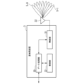
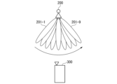
- FIG. 5 is a diagram showing an example of wireless communication device 200 that uses beamforming in the millimeter wave band.
- Radio communication apparatus 200 forms a plurality of directional beams (directional beam 201-1 to directional beam 201 -9).
- wireless communication device 200 selects directional beam 201 based on SLS (Sector Level Sweep) (see Non-Patent Document 2).
- Radio communication apparatus 200 which is the side that initiates communication (initiator), uses directional beams 201 sequentially transmitted from directional beams 201-1 to 201-9 to time-divide radio signals. to the wireless communication device 300 in order. That is, radio communication apparatus 200 transmits radio signals to radio communication apparatus 300 in a time-division manner by sequentially transmitting directional beams (beam sweep).
- the wireless communication device 300 that responds to the communication (responder) receives the signal transmitted from the wireless communication device 200 in time division using the directional beams 201 that are sequentially transmitted.
- Wireless communication apparatus 300 measures the reception power of directional beams 201 sequentially transmitted with its own directional beam width as the maximum beam width.
- the wireless communication device 300 shares with the wireless communication device 200 the identification information (ID) of the directional beam 201 for which the maximum received power is obtained among the directional beams 201 sequentially transmitted. This completes the selection of directional beam 201 .
- wireless communication device 300 may transmit a wireless signal to wireless communication device 200 using a directional beam.
- the radio communication device 200 transmits a plurality of signal blocks "SS/PBCH (Synchronization Signal/Physical Broadcast CHannel)" for each directional beam in a time division manner to the radio communication device 300 (terminal station equipment).
- Radio communication apparatus 300 identifies a directional beam that provides the maximum received power based on a plurality of signal blocks.
- Radio communication apparatus 300 feeds back identification information (ID) of the specified directional beam to radio communication apparatus 200 . This completes the initial selection of directional beam 201 .
- ID identification information
- Non-Patent Document 3 discloses a wireless communication device equipped with a ranging function unit based on the round-trip time (RTT: Round-Trip-Time) of wireless signals.
- RTT Round-Trip-Time
- FIG. 6 is a diagram showing a configuration example of the wireless communication system 10.
- the radio communication system 10 is a distributed antenna system using a high frequency band (see Non-Patent Document 4).
- a radio communication system 10 a plurality of base station apparatuses 12 are distributed in a radio service area 14.
- FIG. The communication control device 11 selects the optimum base station device 12 and directional beam for communication with a predetermined terminal station device 13 .
- the base station apparatuses 12 are distributed within an area where the base station apparatuses 12 can communicate with each other.
- the position of the terminal station device in the wireless service area may be estimated based on the position of the base station device located in the wireless service area. In this case, it is important to estimate the position of the reference base station apparatus.
- the position of a base station device may be measured based on radio waves transmitted from artificial satellites of the Global Navigation Satellite System (GNSS).
- GNSS Global Navigation Satellite System
- Global positioning satellite systems include, for example, GPS (Global Positioning System) and GLONASS (GLOBal Navigation Satellite System).
- the base station equipment in order to use the global positioning satellite system, it is necessary for the base station equipment to be equipped with an antenna dedicated to positioning and a radio section dedicated to positioning. Also, the base station apparatus can use the global positioning satellite system only in an outdoor environment where the satellites can be seen. As described above, there is a problem that the base station apparatus cannot use the global positioning satellite system in a position where the satellite cannot be seen (for example, in an indoor environment).
- the present invention aims to provide a position estimation method, a radio communication device, and a radio communication system capable of estimating the position of a base station device placed in a position where artificial satellites cannot be seen. purpose.
- One aspect of the present invention is a position estimation method executed by a wireless communication system including a wireless communication device and another wireless communication device, wherein the wireless communication device and the other wireless communication device use a directional beam to a radio step of performing radio communication between; a direction of the directional beam in which the reception power of the directional beam is maximized in the other radio communication device; and the radio communication device and the other radio communication device a relative position estimating step of estimating the relative position of the other wireless communication device with respect to the wireless communication device based on the distance according to the round trip time of the wireless signal between the absolute position of the wireless communication device and the other and an absolute position estimation step of estimating the absolute position of the other wireless communication device based on the relative positions of the other wireless communication devices.
- a radio unit performs radio communication between a radio communication device and another radio communication device using a directional beam, and the other radio communication device receives the directional beam.
- the other wireless communication device Based on the direction of the directional beam with the maximum power and the distance according to the round trip time of the radio signal between the own wireless communication device and the other wireless communication device, the other wireless communication device a data processing unit for estimating the relative position of the wireless communication device, and estimating the absolute position of the other wireless communication device based on the absolute position of the own wireless communication device and the relative position of the other wireless communication device; A wireless communication device.
- One aspect of the present invention is a wireless communication system including a wireless communication device and another wireless communication device, wherein a directional beam is used to perform wireless communication between the wireless communication device and the other wireless communication device.
- the direction of the directional beam that maximizes the reception power of the directional beam in the other radio communication device; and the transmission of radio signals between the radio communication device and the other radio communication device.
- estimating the relative position of the other wireless communication device with respect to the wireless communication device based on the distance according to the round trip time, and based on the absolute position of the wireless communication device and the relative position of the other wireless communication device and a data processing unit for estimating the absolute position of the other wireless communication device.
- FIG. 1 is a diagram showing a configuration example of a wireless communication system in an embodiment
- FIG. FIG. 3 is a diagram showing a configuration example of a base station apparatus in an embodiment
- 4 is a flow chart showing an operation example of the base station device in the embodiment
- 1 is a diagram illustrating an example hardware configuration of a wireless communication device in an embodiment
- FIG. 1 is a diagram illustrating an example of a wireless communication device using beamforming in a millimeter wave band
- FIG. It is a figure which shows the structural example of a radio
- Line-of-sight waves are mainly used in high-frequency band communications because radio waves in the high-frequency band travel in a straight line. Based on the direction and distance of such radio waves (directional beams), a wireless communication device (first base station device) in a distributed antenna system estimates the position of another wireless communication device (second base station device). It is possible to
- FIG. 1 is a diagram showing a configuration example of a wireless communication system 1 according to the embodiment.
- the wireless communication system 1 is a distributed antenna system using high frequency bands (millimeter waves and quasi-millimeter waves).
- a radio communication system 1 includes a communication control device 2 and a plurality of base station devices 3 .
- the number of base station apparatuses 3 is seven as an example.
- a plurality of base station devices 3 are distributed in a wireless service area 4 as respective wireless communication devices (each wireless station device).
- the base station device 3-1 is placed in an outdoor environment where an artificial satellite can be seen from the base station device.
- the position of the base station device 3-1 is known.
- each base station device 3 from the base station device 3-2 to the base station device 3-7 is arranged in an indoor environment where the artificial satellite cannot be seen from the base station device.
- one or more terminal station devices may exist in the wireless service area 4 as wireless communication devices that are communication partners of the plurality of base station devices 3 .
- These terminal station devices are, for example, smartphone terminals, tablet terminals, and mobile terminals.
- the base station devices 3 are wireless communication devices distributed in the wireless service area 4 in the distributed antenna system. Note that the division of functions between the higher network of the base station device 3 and the base station device 3 is not limited to a specific division of functions.
- a part of the hardware required for the terminal station apparatus with which the base station apparatus 3 communicates, and a part of the hardware required for the base station apparatus 3 are wireless communication compatible with a specific communication standard.
- the device hardware eg, radio unit, antenna, processor
- the device hardware is common. Therefore, whether the wireless communication device operates as the base station device 3 or as the terminal station device depends on a processor (for example, a data processing unit, a control unit) that controls the hardware of the wireless communication device. software is switched. Therefore, it is possible to operate the wireless communication device arranged as the base station device 3 as a terminal station device.
- the communication control device 2 controls a plurality of distributed base station devices 3, but the CU (Centralized Unit), DU (Distributed Unit) and RU (Radio Unit) in "5G NR" and three or more wireless communication devices may operate as the base station device 3 .
- An autonomous decentralized wireless communication device may operate as the base station device 3 like a base station device in IEEE 802.11ad.
- the function of the base station device 3-2 is temporarily switched to that of the terminal station device so that the base station device 3-2 temporarily operates as the terminal station device.
- the base station device 3-1 estimates the relative position of the base station device 3-2 with respect to the base station device 3-1. In this way, the position of the base station device 3-2, which is placed at a position where the satellite cannot be seen, is estimated.
- the communication control device 2 controls the operation of each base station device 3.
- the communication control device 2 causes the base station device 3-2 to perform the operation of the terminal station device as the communication partner of the base station device 3-1.
- the communication control device 2 switches the operation (function) of the base station device 3-2 so as to temporarily operate the base station device 3-2 as a terminal station device with which the base station device 3-1 communicates.
- the base station device 3-2 executes the operation of the terminal station device based on instructions from the outside of the base station device 3-2 (for example, the communication control device 2).
- the base station device 3-1 can communicate with the base station device 3-2 using the directional beam 5 of the radio signal, according to the communication standard.
- the communication control device 2 causes the base station device 3-2 to perform the operation of the base station device.
- the base station device 3-1 In order to estimate the position of the base station device 3 other than the base station device 3-2, the base station device 3-1 communicates with the base station device 3 other than the base station device 3-2. may be executed.
- the base station device 3-1 performs sequential transmission of directional beams (beam sweep) when performing beamforming.
- the base station device 3-1 regards the direction of the directional beam 5 that maximizes the received power of the directional beam 5 at the base station device 3-2 as the direction of the base station device 3-2 with respect to the base station device 3-1. presume.
- the base station device 3-1 executes distance measurement processing based on the round-trip time of the radio signal between the base station device 3-1 and the base station device 3-2. Estimate the distance to the device 3-2.
- the base station device 3-1 performs distance measurement processing based on the distance attenuation characteristics of the radio signal between the base station device 3-1 and the base station device 3-2, so that the base station device 3-1 and the base station device 3-2 A distance to the station device 3-2 may be estimated.
- the base station device 3-1 Based on the direction of the base station device 3-2 with respect to the base station device 3-1 and the distance between the base station device 3-1 and the base station device 3-2, the base station device 3-1 Estimate the relative position of the base station apparatus 3-2 with respect to 3-1.
- the base station device 3-1 Since the absolute position of the base station device 3-1 is known using the global positioning satellite system or the like, even if the base station device 3-2 exists outside the global positioning satellite system (for example, indoor environment), Based on the relative position of the base station device 3-2 with respect to the base station device 3-1, the base station device 3-1 can estimate the absolute position of the base station device 3-2.
- the base station device 3-1 may transmit the absolute position of the base station device 3-2 to the communication control device 2 and the base station device 3-2.
- FIG. 2 is a diagram showing a configuration example of the base station device 3 in the embodiment.
- the base station device 3 radio communication device
- the base station device 3 includes a data processing section 30 , a radio section 31 , an antenna 32 and a control section 33 .
- the data processing unit 30 executes data processing for operating as a base station device that supports a predetermined communication standard. For example, the data processing unit 30 acquires from the wireless unit 31 a connection request received from another base station device 3 operating as a terminal station device. Based on the connection request, the data processing unit 30 executes connection management of the other base station apparatus 3 that has transmitted the connection request. For example, the data processing unit 30 outputs data input from an upper network (not shown) to the wireless unit 31 . For example, the data processing unit 30 outputs data input from the wireless unit 31 to a host network (not shown). The data processing unit 30 may output data input from the wireless unit 31 to an interface of a higher network (not shown).
- the data processing unit 30 determines that the own base station apparatus is a terminal station apparatus that supports a predetermined communication standard. Perform data processing to operate. For example, the data processing unit 30 outputs, to the radio unit 31, data transmitted from its own base station apparatus toward the base station apparatus 3 that executes the ranging process.
- the radio unit 31 transmits the data output from the data processing unit 30 as a radio signal from the antenna 32 by performing beamforming of the directional beam 5 .
- the radio section 31 outputs data corresponding to radio signals received using the antenna 32 to the data processing section 30 .
- the control unit 33 switches the software of the data processing unit 30 based on a predetermined trigger so that the data processing unit 30 operates as a base station device or as a terminal station device.
- the data processing unit 30 is instructed to do so.
- the control unit 33 causes the data processing unit 30 to perform functions as a base station apparatus defined in the communication standard.
- the function as a base station device is, for example, a function of measuring the distance between a terminal station device existing in the surroundings and its own base station device.
- the control unit 33 causes the data processing unit 30 to perform the function as a base station apparatus defined in the communication standard,
- the data processing unit 30 is caused to perform the function as a terminal station device defined in the communication standard.
- the function as a terminal station device is, for example, a function of detecting (searching for) other base station devices 3 existing in the vicinity.
- the control unit 33 causes the data processing unit 30 to execute a process of transmitting a connection request to that base station device 3 .
- Triggers such as
- (A-1) Trigger Caused by New Placement of Base Station Device 3 in Wireless Service Area 4
- the base station device 3 Temporarily operate as a station device.
- the control unit 33 of the newly arranged base station device 3 switches the function of the data processing unit 30 so that its own base station device temporarily operates as a terminal station device.
- A-2) Trigger caused by communication control device 2 (upper device) periodically instructing control unit 33 of arbitrary base station device 3 Relatively small base station device (for example, wireless LAN ( It is easy to move the location of a Local Area Network (Access Point). Therefore, there is a possibility that the base station device 3 will move together with the movement of furniture indoors.
- the communication control device 2 (upper device) periodically transmits a function switching instruction to the base station device 3 .
- the communication control device 2 may estimate the position of each base station device 3 in the wireless service area 4 using base station devices 3 whose absolute positions in the wireless service area 4 are known.
- (A-3) Trigger Caused by Zero Terminal Station Devices Communication-Connected to the Base Station Device 3
- the base station device 3 operates as a terminal station device. That is, when there is no communication partner of the base station device 3, the base station device 3 operates as a terminal station device. This allows the base station device 3 to operate as a terminal station device even when there is no instruction to the base station device 3 from the outside.
- (B-1) Trigger Caused by Predetermined Time Timer Simultaneously with switching the operation of the data processing section 30 to temporarily operate as a terminal station apparatus, the control section 33 sets a predetermined time timer. Upon expiration of the timer, the control unit 33 switches the operation (function) of the data processing unit 30 so that the base station device 3 operates as a base station device.
- (B-2) Trigger caused by an instruction transmitted from at least one of the communication control device 2 and another base station device facing the own base station device
- the base station device 3 operating as a terminal station device When the estimation of the position of the radio communication device) is completed, the base station device 3 or the communication control device 2 that performed the distance measurement process transmits an estimation completion signal to the base station device 3 .
- the control unit 33 of the base station device 3 operating as the terminal station device acquires the estimation completion signal, it transmits a function switching instruction to the data processing unit 30 so that the own base station device operates as the base station device. do.
- FIG. 3 is a flowchart showing an operation example of the wireless communication system 1 in the embodiment.
- the radio unit 31 of the base station device 3-1 (first radio communication device) uses the directional beam 5 of the radio signal to communicate with the base station device 3-1 and the base station device 3-2 (second radio communication device). (step S101).
- the data processing unit 30 of the base station 3-1 determines the direction of the directional beam 5 that maximizes the reception power of the directional beam 5 at the base station 3-2. is estimated (step S102).
- the data processing unit 30 of the base station device 3-1 determines the distance between the base station device 3-1 and the base station device 3-2 based on the round-trip time of the radio signal between the base station device 3-1 and the base station device 3-2. -2 is estimated (step S103).
- the data processing unit 30 of the base station device 3-1 estimates the relative position of the base station device 3-2 with respect to the base station device 3-1 based on the estimated direction and distance (step S104).
- the data processing unit 30 of the base station device 3-1 estimates the absolute position of the base station device 3-2 based on the absolute position of the base station device 3-1 and the relative position of the base station device 3-2 ( step S105).
- the radio unit 31 uses directional beams to perform radio communication between the base station devices 3-1 and 3-2.
- the data processing unit 30 estimates the direction of the directional beam that maximizes the reception power of the directional beam in the base station device 3-2.
- the data processing unit 30 estimates the distance according to the round trip time of the radio signal between the base station device 3-1 and the base station device 3-2. That is, the data processing unit 30 estimates the distance between the base station device 3-1 and the base station device 3-2.
- the data processing unit 30 estimates the relative position of the base station device 3-2 with respect to the base station device 3-1 based on the estimated direction and the estimated distance.
- the data processing unit 30 estimates the absolute position of the base station device 3-2 based on the absolute position of the base station device 3-1 and the relative position of the base station device 3-2.
- the internal processing (software) of the data processing unit 30 (processor) of the base station device 3 is rewritten to switch whether the base station device 3 operates as a base station device or as a terminal station device. It is On the other hand, the base station device 3 physically separates a first data processing unit (processor) that performs operations as a base station device and a second data processing unit (processor) that performs operations as a terminal station device. You can prepare for it.
- FIG. 4 is a diagram showing a hardware configuration example of the wireless communication device 100 in each embodiment.
- Radio communication apparatus 100 corresponds to base station apparatus 3 .
- Some or all of the functional units of the wireless communication device 100 are configured by a processor 101 such as a CPU (Central Processing Unit), a storage device 102 having a non-volatile recording medium (non-temporary recording medium), and a memory 103. It is implemented as software by executing a program stored in the . The program may be recorded on a computer-readable non-transitory recording medium.
- a processor 101 such as a CPU (Central Processing Unit), a storage device 102 having a non-volatile recording medium (non-temporary recording medium), and a memory 103. It is implemented as software by executing a program stored in the . The program may be recorded on a computer-readable non-transitory recording medium.
- a computer-readable non-temporary recording medium is, for example, a portable medium such as a flexible disk, a magneto-optical disk, a ROM (Read Only Memory), a CD-ROM (Compact Disc Read Only Memory), or a hard disk built into a computer system. It is a non-temporary recording medium such as a storage device such as The communication unit 104 executes predetermined communication processing. The communication unit 104 may acquire data and programs.
- Some or all of the functional units of the wireless communication device 100 are, for example, LSI (Large Scale Integrated circuit), ASIC (Application Specific Integrated Circuit), PLD (Programmable Logic Device), or FPGA (Field Programmable Gate Array). may be implemented using hardware including electronic circuits or circuitry.
- LSI Large Scale Integrated circuit
- ASIC Application Specific Integrated Circuit
- PLD Programmable Logic Device
- FPGA Field Programmable Gate Array
- the present invention is applicable to distributed antenna systems.
Landscapes
- Engineering & Computer Science (AREA)
- Radar, Positioning & Navigation (AREA)
- Remote Sensing (AREA)
- Physics & Mathematics (AREA)
- General Physics & Mathematics (AREA)
- Computer Networks & Wireless Communication (AREA)
- Mobile Radio Communication Systems (AREA)
Priority Applications (4)
| Application Number | Priority Date | Filing Date | Title |
|---|---|---|---|
| JP2023539550A JP7648948B2 (ja) | 2021-08-06 | 2021-08-06 | 位置推定方法、無線通信装置及び無線通信システム |
| US18/291,896 US20250052888A1 (en) | 2021-08-06 | 2021-08-06 | Position estimation method, wireless communication apparatus and wireless communication system |
| EP21952863.5A EP4382964A4 (en) | 2021-08-06 | 2021-08-06 | Position estimation method, wireless communication device, and wireless communication system |
| PCT/JP2021/029326 WO2023013040A1 (ja) | 2021-08-06 | 2021-08-06 | 位置推定方法、無線通信装置及び無線通信システム |
Applications Claiming Priority (1)
| Application Number | Priority Date | Filing Date | Title |
|---|---|---|---|
| PCT/JP2021/029326 WO2023013040A1 (ja) | 2021-08-06 | 2021-08-06 | 位置推定方法、無線通信装置及び無線通信システム |
Publications (1)
| Publication Number | Publication Date |
|---|---|
| WO2023013040A1 true WO2023013040A1 (ja) | 2023-02-09 |
Family
ID=85155416
Family Applications (1)
| Application Number | Title | Priority Date | Filing Date |
|---|---|---|---|
| PCT/JP2021/029326 Ceased WO2023013040A1 (ja) | 2021-08-06 | 2021-08-06 | 位置推定方法、無線通信装置及び無線通信システム |
Country Status (4)
| Country | Link |
|---|---|
| US (1) | US20250052888A1 (https=) |
| EP (1) | EP4382964A4 (https=) |
| JP (1) | JP7648948B2 (https=) |
| WO (1) | WO2023013040A1 (https=) |
Citations (1)
| Publication number | Priority date | Publication date | Assignee | Title |
|---|---|---|---|---|
| JP2010151807A (ja) * | 2008-11-19 | 2010-07-08 | Panasonic Corp | 無線測位装置及び座標構成方法 |
Family Cites Families (8)
| Publication number | Priority date | Publication date | Assignee | Title |
|---|---|---|---|---|
| JP2007248362A (ja) | 2006-03-17 | 2007-09-27 | Hitachi Ltd | 端末測位システム及び位置測定方法 |
| US20120014412A1 (en) * | 2009-03-17 | 2012-01-19 | Panasonic Corporation | Positioning system and positioning method |
| US20140162702A1 (en) * | 2012-07-11 | 2014-06-12 | Brandon Robert Crawford | Decentralized Location Triangulation System and Data Transfer Protocol |
| CN108267763B (zh) | 2017-01-03 | 2021-01-15 | 华为技术有限公司 | 用于定位的方法和装置 |
| JP6916491B6 (ja) | 2018-05-24 | 2021-09-08 | イネーブラー株式会社 | 測位システム、基地局、および、測位方法 |
| US20210058890A1 (en) * | 2019-08-23 | 2021-02-25 | Qualcomm Incorporated | Bandwidth indication in positioning measurement reports |
| US12022423B2 (en) * | 2019-10-18 | 2024-06-25 | Qualcomm Incorporated | Integrated access backhaul (IAB) node positioning |
| CN112752340B (zh) * | 2020-12-31 | 2022-12-27 | Oppo广东移动通信有限公司 | 基站位置标定方法、存储介质及定位基站 |
-
2021
- 2021-08-06 JP JP2023539550A patent/JP7648948B2/ja active Active
- 2021-08-06 EP EP21952863.5A patent/EP4382964A4/en active Pending
- 2021-08-06 WO PCT/JP2021/029326 patent/WO2023013040A1/ja not_active Ceased
- 2021-08-06 US US18/291,896 patent/US20250052888A1/en active Pending
Patent Citations (1)
| Publication number | Priority date | Publication date | Assignee | Title |
|---|---|---|---|---|
| JP2010151807A (ja) * | 2008-11-19 | 2010-07-08 | Panasonic Corp | 無線測位装置及び座標構成方法 |
Non-Patent Citations (5)
| Title |
|---|
| "Part 11: Radio LAN Medium Access Control (MAC) and Physical Layer (PHY) Specifications Amendment 3: Enhancements for Very High Throughput in the 60 GHz Band", IEEE STD 802.11AD-2012, 28 December 2012 (2012-12-28) |
| IWAKUNI ET AL.: "Experimental evaluation for handover control using a ranging function in high frequency band radio communication system", B-5-56, 2020 IEICE SOCIETY CONFERENCE |
| See also references of EP4382964A4 |
| TAKINAMI ET AL.: "Standardization Trend and Elemental Technology for Millimeter Wave Band Radio LAN System", IEICE COMMUNICATION SOCIETY MAGAZINE, vol. 38, 2016, pages 100 - 106 |
| UCHIDA: "A study of high-frequency band distributed antenna system in terminal high-density and shielded environments", 2020 IEICE SOCIETY CONFERENCE, B-5-87 |
Also Published As
| Publication number | Publication date |
|---|---|
| EP4382964A1 (en) | 2024-06-12 |
| US20250052888A1 (en) | 2025-02-13 |
| EP4382964A4 (en) | 2025-06-04 |
| JP7648948B2 (ja) | 2025-03-19 |
| JPWO2023013040A1 (https=) | 2023-02-09 |
Similar Documents
| Publication | Publication Date | Title |
|---|---|---|
| KR102525483B1 (ko) | 측정 방법 및 장치 | |
| US20220386265A1 (en) | Positioning method and apparatus | |
| JP7388609B2 (ja) | ビーム構成方法および装置 | |
| US8818419B2 (en) | Method and system for device positioning utilizing distributed transceivers with array processing | |
| US11265072B2 (en) | Apparatus and method for beam alignment based on location information in wireless communication system | |
| WO2018133036A1 (en) | Methods, base stations, and user equipments for measurement before handover | |
| US12308926B2 (en) | Apparatus for selecting radio beams | |
| KR102462464B1 (ko) | 통신 방법 및 장치 | |
| CN116057404A (zh) | 无线通信系统中双基地和多基地雷达的tx/rx参数的信令 | |
| US12273161B2 (en) | Estimating a link budget | |
| CN115623587A (zh) | 终端设备的定位 | |
| CN114128313A (zh) | 通信方法、装置、设备、系统及存储介质 | |
| WO2023036448A1 (en) | Ris-based localization method and system empowered by a joint bs-ris beam alignment | |
| US20250374230A1 (en) | Communication method and communication apparatus | |
| CA3190146A1 (en) | Communication method, apparatus, and system | |
| CN107258106B (zh) | 通信设备、接入节点及其方法 | |
| WO2023040796A1 (zh) | 一种通道相位偏差预测方法及相关设备 | |
| CN115915170B (zh) | 一种波束切换方法及装置 | |
| WO2024092825A1 (zh) | 终端设备位置验证方法及装置 | |
| JP7755212B2 (ja) | 無線通信システム、位置推定方法及び無線通信装置 | |
| JP7648948B2 (ja) | 位置推定方法、無線通信装置及び無線通信システム | |
| WO2022024241A1 (ja) | 無線通信方法及び端末局装置 | |
| WO2024189841A1 (ja) | 無線通信システム、制御装置、電源制御方法及びプログラム | |
| CN116888986A (zh) | 用于定位的方法、终端设备和网络设备 | |
| US20250351110A1 (en) | Position determination of a user equipment |
Legal Events
| Date | Code | Title | Description |
|---|---|---|---|
| 121 | Ep: the epo has been informed by wipo that ep was designated in this application |
Ref document number: 21952863 Country of ref document: EP Kind code of ref document: A1 |
|
| WWE | Wipo information: entry into national phase |
Ref document number: 2023539550 Country of ref document: JP |
|
| NENP | Non-entry into the national phase |
Ref country code: DE |
|
| ENP | Entry into the national phase |
Ref document number: 2021952863 Country of ref document: EP Effective date: 20240306 |