WO2023008554A1 - 球面リンク作動装置 - Google Patents
球面リンク作動装置 Download PDFInfo
- Publication number
- WO2023008554A1 WO2023008554A1 PCT/JP2022/029275 JP2022029275W WO2023008554A1 WO 2023008554 A1 WO2023008554 A1 WO 2023008554A1 JP 2022029275 W JP2022029275 W JP 2022029275W WO 2023008554 A1 WO2023008554 A1 WO 2023008554A1
- Authority
- WO
- WIPO (PCT)
- Prior art keywords
- link
- pulley
- spherical
- string
- hub
- Prior art date
- Legal status (The legal status is an assumption and is not a legal conclusion. Google has not performed a legal analysis and makes no representation as to the accuracy of the status listed.)
- Ceased
Links
Images








Classifications
-
- B—PERFORMING OPERATIONS; TRANSPORTING
- B25—HAND TOOLS; PORTABLE POWER-DRIVEN TOOLS; MANIPULATORS
- B25J—MANIPULATORS; CHAMBERS PROVIDED WITH MANIPULATION DEVICES
- B25J11/00—Manipulators not otherwise provided for
-
- F—MECHANICAL ENGINEERING; LIGHTING; HEATING; WEAPONS; BLASTING
- F16—ENGINEERING ELEMENTS AND UNITS; GENERAL MEASURES FOR PRODUCING AND MAINTAINING EFFECTIVE FUNCTIONING OF MACHINES OR INSTALLATIONS; THERMAL INSULATION IN GENERAL
- F16H—GEARING
- F16H21/00—Gearings comprising primarily only links or levers, with or without slides
- F16H21/46—Gearings comprising primarily only links or levers, with or without slides with movements in three dimensions [3D]
- F16H21/50—Gearings comprising primarily only links or levers, with or without slides with movements in three dimensions [3D] for interconverting rotary motion and reciprocating motion
-
- F—MECHANICAL ENGINEERING; LIGHTING; HEATING; WEAPONS; BLASTING
- F16—ENGINEERING ELEMENTS AND UNITS; GENERAL MEASURES FOR PRODUCING AND MAINTAINING EFFECTIVE FUNCTIONING OF MACHINES OR INSTALLATIONS; THERMAL INSULATION IN GENERAL
- F16H—GEARING
- F16H21/00—Gearings comprising primarily only links or levers, with or without slides
- F16H21/46—Gearings comprising primarily only links or levers, with or without slides with movements in three dimensions [3D]
- F16H21/54—Gearings comprising primarily only links or levers, with or without slides with movements in three dimensions [3D] for conveying or interconverting oscillating or reciprocating motions
-
- F—MECHANICAL ENGINEERING; LIGHTING; HEATING; WEAPONS; BLASTING
- F16—ENGINEERING ELEMENTS AND UNITS; GENERAL MEASURES FOR PRODUCING AND MAINTAINING EFFECTIVE FUNCTIONING OF MACHINES OR INSTALLATIONS; THERMAL INSULATION IN GENERAL
- F16H—GEARING
- F16H37/00—Combinations of mechanical gearings, not provided for in groups F16H1/00 - F16H35/00
- F16H37/02—Combinations of mechanical gearings, not provided for in groups F16H1/00 - F16H35/00 comprising essentially only toothed or friction gearings
-
- F—MECHANICAL ENGINEERING; LIGHTING; HEATING; WEAPONS; BLASTING
- F16—ENGINEERING ELEMENTS AND UNITS; GENERAL MEASURES FOR PRODUCING AND MAINTAINING EFFECTIVE FUNCTIONING OF MACHINES OR INSTALLATIONS; THERMAL INSULATION IN GENERAL
- F16H—GEARING
- F16H37/00—Combinations of mechanical gearings, not provided for in groups F16H1/00 - F16H35/00
- F16H37/12—Gearings comprising primarily toothed or friction gearing, links or levers, and cams, or members of at least two of these types
Definitions
- the present invention relates to a spherical link actuator.
- Patent Document 1 describes a link actuating device.
- the link actuating device described in Patent Document 1 has a spherical link mechanism and a plurality of posture changing actuators.
- the spherical link mechanism has a proximal end link hub, a distal end link hub, and a plurality of links.
- a plurality of links connect the proximal link hub and the distal link hub.
- Each of the plurality of links has a proximal link member, a distal link member and an intermediate link member.
- the base end link member is connected to the base end link hub at one end of the base end link member so as to be rotatable around the first rotation axis.
- the tip link member is connected to the tip link hub at one end of the tip link member so as to be rotatable around the second rotation axis.
- the intermediate link member is connected at one end of the intermediate link member to the other end of the proximal link member so as to be rotatable about the third rotation axis, and is rotatable at the other end of the intermediate link member about the fourth rotation axis. is connected to the other end of the tip link member.
- the center axis of the base end link hub, the first rotation axis and the third rotation axis intersect at one point. This one point is defined as the center point of the first spherical link.
- the center axis of the tip link hub, the second rotation axis and the fourth rotation axis intersect at a point different from the center point of the first spherical link. This other point is set as the center point of the second spherical link.
- the proximal link hub moves on a spherical surface centered on the first spherical link center point.
- the tip link hub moves on a spherical surface centered on the second spherical link center point. That is, the spherical link mechanism is configured by combining two spherical link mechanisms.
- each of the plurality of posture changing actuators rotates the base end link member of each of the plurality of links around the first rotation axis, thereby moving the base end link hub of the tip link hub. The position and attitude with respect to is changed.
- a plurality of posture changing actuators are arranged radially around the base end link hub. I can't help it. That is, in a plurality of link actuating devices, the arrangement of a plurality of posture changing actuators is greatly restricted.
- the present invention has been made in view of the problems of the prior art as described above. More specifically, the present invention provides a spherical link actuation device capable of increasing the degree of freedom in arranging the drive source.
- the spherical link actuator of the present invention includes a spherical link mechanism, a plurality of string members, and a plurality of drive sources.
- the spherical linkage has a proximal link hub, a distal link hub, and a plurality of links connecting the proximal and distal link hubs.
- Each of the plurality of links includes a proximal link member, a distal link member and an intermediate link member.
- the proximal link member is connected to the proximal link hub at one end thereof so as to be rotatable around the first rotation axis.
- the tip link member is connected to the tip link hub at one end of the tip link member so as to be rotatable around the second rotation axis.
- the intermediate link member is connected at one end of the intermediate link member to the other end of the base end link member so as to be rotatable around the third rotation axis, and is connected at the other end of the intermediate link member to the other end of the distal link member. 4 It is connected so as to be rotatable around the rotation axis.
- the center axis of the proximal link hub, the first rotation axis and the third rotation axis intersect at the first spherical link center point.
- the center axis of the tip link hub, the second rotation axis and the fourth rotation axis intersect at the second spherical link center point.
- the proximal link hub and the distal link hub respectively move on a first moving spherical surface centered on the first spherical link center point and on a second moving spherical surface centered on the second spherical link center point.
- Each of the plurality of string-like members is connected to each of the plurality of drive sources and the spherical link mechanism.
- the power of each of the plurality of drive sources is transmitted to the spherical link mechanism via each of the plurality of string members, thereby changing the position and attitude of the distal end link hub relative to the proximal end link hub.
- each of the plurality of drive sources may adjust the tension applied to each of the plurality of string-like members, thereby changing the position and orientation of the distal link hub relative to the proximal link hub.
- each of the plurality of string-like members may connect the intermediate link member of each of the plurality of links and each of the plurality of drive sources.
- the above spherical link actuator may further comprise a plurality of pulleys attached to the proximal link hub.
- Each of the plurality of pulleys may have a pulley and a pulley fixed shaft member and be attached to the proximal link hub by the pulley fixed shaft member.
- Each of the plurality of string members may be relayed by pulleys of each of the plurality of pulleys.
- the pulley in each of the plurality of pulleys may be rotatable around the central axis of the pulley fixed shaft member with one degree of freedom.
- the central axis of the pulley fixed shaft member may pass through the center point of the first spherical link.
- the spherical link actuator described above may further include a plurality of first pulleys and a plurality of second pulleys.
- Each of the plurality of string-like members may connect the tip link hub and each of the plurality of drive sources.
- Each of the plurality of first pulleys may have a first pulley and a first pulley fixed shaft member, and may be attached to the proximal link hub by the first pulley fixed shaft member.
- Each of the plurality of second pulleys may have a second pulley and a second pulley fixed shaft member, and may be attached to an intermediate link member of each of the plurality of links by the second pulley fixed shaft member.
- Each of the plurality of string-shaped members may be relayed by a first pulley of each of the plurality of first pulleys and a second pulley of each of the plurality of second pulleys.
- the first pulley of each of the plurality of first pulleys may be rotatable about the central axis of the first pulley fixed shaft member with one rotational degree of freedom.
- Each of the plurality of second pulleys may be non-rotatable with respect to each intermediate link member of the plurality of links.
- the second pulley of each of the plurality of second pulleys may be positioned outside the intermediate link member of each of the plurality of links.
- the second pulley of each of the plurality of second pulleys may be positioned inside the intermediate link member of each of the plurality of links.
- each of the plurality of string-like members may connect the tip link hub or the tip link member of each of the plurality of links and each of the plurality of drive sources.
- each of the plurality of drive sources may have a pulley.
- Each of the plurality of drive sources may adjust the tension applied to each of the plurality of string-like members by rotating a pulley to wind up or let out each of the plurality of string-like members.
- the above spherical link actuator may further comprise a plurality of sensors.
- Each of the plurality of sensors may be configured to be capable of detecting the winding amount or the feeding amount of each of the plurality of string members by the pulleys of the plurality of drive sources.
- the plurality of string members may be a plurality of wires, a plurality of threads, a plurality of chains or a plurality of belts.
- the above spherical link actuator may further comprise a plurality of tensioners.
- Each of the plurality of tensioners may be configured to be able to adjust the tension applied to each of the plurality of string members.
- each of the plurality of drive sources rotates the base end link member of each of the plurality of links around the first rotation axis via each of the plurality of string members, thereby
- the position and orientation of the hub may vary.
- the plurality of cord-like members may be a plurality of annular timing belts.
- Each of the plurality of drive sources may have a timing pulley.
- a base end link member of each of the plurality of links and a timing pulley of each of the plurality of drive sources may be connected by each of a plurality of annular timing belts.
- the above spherical link actuation device may further include a plurality of pulleys and a plurality of drive conversion units.
- Each of the plurality of pulleys may have a first pulley and a pulley fixed shaft member and be attached to the proximal link hub by the pulley fixed shaft member.
- the first pulley may be rotatable with one rotational degree of freedom around the central axis of the pulley fixed shaft member.
- Each of the plurality of drive conversion units includes a support portion, a second pulley attached to the support portion, a first gear that rotates together with the second pulley, and a second gear to which the rotational force of the first gear is transmitted.
- Each of the plurality of string members may be relayed to the first pulley of each of the plurality of pulleys to connect the second pulley of each of the plurality of drive sources and each of the plurality of drive sources.
- the gear fixing shaft member of each of the plurality of drive conversion parts is fixed to one end of each tip link member of each of the plurality of links, and is connected to the tip link hub rotatably around the second rotation axis. good too.
- the support part may be rotatable around the second rotation axis independently from the gear fixing shaft member.
- the first pulley of each of the plurality of pulleys may be arranged on the same plane as the second pulley of each of the plurality of drive converting portions.
- the above spherical link actuator may further comprise a plurality of tension adjusting mechanisms.
- Each of the plurality of tension adjusting mechanisms is configured to be able to adjust the tension applied to each of the plurality of cord-like members between the first pulley of each of the plurality of pulleys and the second pulley of each of the plurality of drive sources.
- each of the plurality of drive sources rotates the base end link member and the tip end link member of each of the plurality of links around the first rotation axis and the second rotation axis via each of the plurality of string members. They may be simultaneously rotated around the rotation axis.
- the rotation direction of the base end link member about the first rotation axis is opposite to the rotation direction of the tip link member about the second rotation axis, and the base end link member rotates about the first rotation axis.
- the amount of rotation may be the same as the amount of rotation of the tip link member about the second rotation axis.
- each of the plurality of string-like members may be connected to the proximal end link member and the distal end link member after being relayed by the intermediate link member in each of the plurality of links.
- the spherical link actuator of the present invention it is possible to increase the degree of freedom in arranging the drive source.
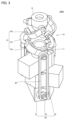
- FIG. 1 is a perspective view of a spherical link actuator 100;
- FIG. 2 is a front view of the spherical link actuator 100;
- FIG. It is a perspective view of spherical link actuator 100A.
- Fig. 10 is a perspective view of the spherical link actuator 100A when the bending angle of the distal end link hub 12 with respect to the proximal end link hub 11 is 90°; It is a perspective view of the spherical link actuator 100B. It is a front view of the spherical link actuator 100B.
- Fig. 10 is a perspective view of the spherical link actuator 100A when the bending angle of the distal end link hub 12 with respect to the proximal end link hub 11 is 90°;
- FIG. 10 is a perspective view of the spherical link actuator 100B showing the cord-like member 30 without omitting it entirely; It is a perspective view of spherical link actuator 100C.
- Fig. 10 is a perspective view of a pulley 50 included in the spherical link actuator 100C; It is a perspective view of spherical link actuator 100D. It is a front view of spherical link actuator 100D. It is a perspective view of spherical link actuator 100D concerning a modification. It is a perspective view of the spherical link actuator 100E.
- Fig. 10 is a perspective view of a drive converting portion 70 included in the spherical link actuation device 100E;
- a spherical link actuation device (referred to as a "spherical link actuation device 100") according to the first embodiment will be described below.
- FIG. 1 is a perspective view of a spherical link actuator 100.
- FIG. FIG. 2 is a front view of the spherical link actuator 100.
- the spherical link actuator 100 has a spherical link mechanism 10 , multiple drive sources 20 , and multiple cord-like members 30 .
- the spherical link mechanism 10 has a proximal end link hub 11, a distal end link hub 12, and a plurality of links 13.
- the proximal end link hub 11 and the distal end link hub 12 are connected by a plurality of links 13 .
- the number of multiple links 13 is, for example, three. However, the number of multiple links 13 may be two, or may be four or more. A case where the number of the plurality of links 13 is three will be described below as an example.
- the plurality of links 13 are arranged at regular intervals, for example. When a plurality of links 13 are arranged at regular intervals, calculations for the spherical link mechanism 10 are easy to perform. Note that the plurality of links 13 may not be arranged at regular intervals.
- the link 13 has a proximal link member 13a, a distal link member 13b, and an intermediate link member 13c.
- the proximal end link member 13a and the distal end link member 13b are, for example, L-shaped.
- the intermediate link member 13c has, for example, an arc shape.
- the proximal link member 13a is connected to the proximal link hub 11 at one end thereof so as to be rotatable around the first rotation axis. Friction associated with rotation of the proximal end link member 13a with respect to the proximal end link hub 11 may be reduced by a rotational resistance reduction member.
- This rotational resistance reduction member is, for example, a rolling bearing or a sliding bearing.
- the tip link member 13b is connected to the tip link hub 12 at one end of the tip link member 13b so as to be rotatable about the second rotation axis. Friction due to rotation of the tip link member 13b with respect to the tip link hub 12 may be reduced by a rotational resistance reduction member.
- This rotational resistance reduction member is, for example, a rolling bearing or a sliding bearing.
- One end of the intermediate link member 13c is connected to the other end of the base end link member 13a so as to be rotatable around the third rotation axis.
- the intermediate link member 13c is connected at the other end of the intermediate link member 13c to the other end of the tip link member 13b so as to be rotatable around the fourth rotation axis.
- the friction associated with the rotation of the intermediate link member 13c with respect to the base end link member 13a and the friction associated with the rotation of the intermediate link member 13c with respect to the distal end link member 13b may be reduced by a rotational resistance reduction member.
- This rotational resistance reduction member is, for example, a rolling bearing or a sliding bearing.
- the first central axis, the first rotation axis and the third rotation axis intersect at one point.
- This one point is defined as the center point of the first spherical link.
- the second center axis, the second rotation axis, and the fourth rotation axis intersect at a point other than the first spherical link center point. This other point is set as the center point of the second spherical link.
- the distance between the first spherical link center point and the second spherical link center point is constant regardless of the position and orientation of the distal end link hub 12 with respect to the proximal end link hub 11 .
- the base end link hub 11 moves on a spherical surface centered on the center point of the first spherical link. This spherical surface is defined as the first moving spherical surface.
- the tip link hub 12 moves on a spherical surface centered on the second spherical link center point. This spherical surface is referred to as a second movement spherical surface.
- the spherical link mechanism 10 has a structure in which two spherical link mechanisms are combined.
- a plane where the first moving spherical surface and the second moving spherical surface intersect is defined as an intermediate plane.
- the proximal end link hub 11 side of the spherical link mechanism 10 (the portion of the spherical link mechanism 10 that is closer to the proximal end link hub 11 than the intermediate plane) is the distal end link hub 12 side of the spherical link mechanism 10 (intermediate plane The part of the spherical link mechanism 10 on the tip link hub 12 side) always moves symmetrically.
- the number of drive sources 20 is, for example, three. However, the number of drive sources 20 may be two, or may be four or more. A case in which the number of the plurality of drive sources 20 is three will be described below as an example.
- the drive source 20 has a main body 21 (not shown in FIGS. 1 and 2) and a shaft 22 .
- the body portion 21 rotates the shaft body 22 around its central axis.
- the body portion 21 is housed inside the case 40 .
- the shaft 22 is outside the case 40 .
- the drive source 20 is, for example, a motor.
- the spherical link mechanism 10 is arranged on the case 40 .
- the number of multiple string-like members 30 is equal to the number of multiple links 13 . Also, the number of string members 30 is equal to the number of drive sources 20 .
- the string member 30 connects the drive source 20 and the spherical link mechanism 10 . More specifically, the string member 30 connects the shaft 22 and the intermediate link member 13c.
- the string-like member 30 may connect the shaft 22 and the tip link hub 12 .
- the string-like member 30 may connect the shaft 22 and the proximal end link member 13a or the distal end link member 13b.
- the string-like member 30 may connect the pulley attached to the shaft 22 to any one of the tip link hub 12, the base end link member 13a, the tip link member 13b and the intermediate link member 13c.
- the string-like member 30 is, for example, a wire.
- the string-like member 30 may be a thread, a chain or a belt.
- Each of the plurality of drive sources 20 transmits power to the spherical link mechanism 10 via each of the plurality of string members 30, thereby changing the position and posture of the distal end link hub 12 with respect to the proximal end link hub 11. . More specifically, each of the plurality of drive sources 20 adjusts the tension applied to each of the plurality of string members 30 . As a result, the position at which the tension applied to each of the string-like members 30 is balanced changes, and the position and attitude of the distal end link hub 12 with respect to the proximal end link hub 11 are changed.
- the string-like member 30 is wound around the shaft 22 as the main body 21 rotates the shaft 22 .
- the string-like member 30 is drawn out from the shaft body 22 when the main body part 21 reversely rotates the rotating shaft. Thereby, the tension applied to the string-like member 30 is adjusted.
- the spherical link actuator 100 may have multiple sensors. Each of the plurality of sensors is configured to be able to detect the winding amount and the feeding amount of the string-like member 30 in each of the plurality of drive sources 20 . Each of the plurality of drive sources 20 may control the position and posture of the distal end link hub 12 with respect to the proximal end link hub 11 based on the winding amount and the feeding amount of the string member 30 detected by the sensor.
- the spherical link actuator 100 may have multiple tensioners. Each of the plurality of tensioners is arranged near each of the plurality of string members 30 . By bringing the tensioner into contact with the string-like member 30, the tension applied to the string-like member 30 is always properly maintained.
- ⁇ Effect of spherical link actuator 100> power from a plurality of drive sources 20 is transmitted to the spherical link mechanism 10 via a plurality of string members 30, thereby changing the position and posture of the distal link hub 12 with respect to the proximal link hub 11. is changed. Since the spherical link mechanism 10 and the drive source 20 are connected via the string member 30, the arrangement of the drive source 20 can be easily changed by changing the length of the string member 30. . Thus, according to the spherical link actuation device 100, it is possible to increase the degree of freedom in arranging the drive source 20. FIG.
- the spherical link actuation device 100 when used as an end effector of another device, by arranging the drive source 20 at a position away from the spherical link mechanism 10, the other device can move only the spherical link mechanism 10. Therefore, the weight or moment of inertia of the end effector can be reduced.
- the string-like member 30 When any one of a wire, thread, and chain is used as the string-like member 30, even if the string-like member 30 is twisted due to changes in the position and posture of the distal end link hub 12 with respect to the proximal end link hub 11, the string Power can be transmitted through the shaped member 30 .
- a belt is used as the string-like member 30, cutting, slippage, and falling off of the string-like member 30 can be suppressed.
- the position and attitude of the distal link hub 12 relative to the proximal link hub 11 can be controlled near the distal link hub 12.
- a decrease in accuracy in determining the position and attitude of the tip link hub 12 with respect to the base end link hub 11 due to the play (backlash) of the link 13 is suppressed.
- the spherical link actuator 100 When the spherical link actuator 100 has a plurality of tensioners, the power transmission efficiency through the string-shaped member 30 is improved as the slip loss is reduced. Further, in this case, rattling of the link 13 can be suppressed. If the spherical link actuation device 100 has a plurality of sensors, and the position and attitude of the distal link hub 12 with respect to the proximal link hub 11 are controlled based on the outputs of these sensors, the proximal end of the distal link hub 12 can be detected more accurately. A position and attitude with respect to the link hub 11 can be determined.
- a spherical link actuation device (referred to as a “spherical link actuation device 100A”) according to the second embodiment will be described.
- differences from the spherical link actuation device 100 will be mainly described, and redundant description will not be repeated.
- FIG. 3 is a perspective view of the spherical link actuator 100A.
- FIG. 4 is a front view of the spherical link actuator 100A.
- the spherical link actuator 100 ⁇ /b>A has a spherical link mechanism 10 , multiple drive sources 20 , and multiple cord-like members 30 .
- the configuration of the spherical link actuation device 100A is in common with the configuration of the spherical link actuation device 100. As shown in FIG.
- the configuration of the spherical link actuation device 100A differs from the configuration of the spherical link actuation device 100 with respect to the details of the drive source 20 and the string member 30 .
- the body portions 21 of the plurality of drive sources 20 are arranged in an overlapping manner. Further, in the spherical link actuator 100A, the shafts 22 of the plurality of drive sources 20 are arranged so as to be parallel to the first rotation shafts of the plurality of links 13 .
- a timing pulley 23 is attached to the shaft 22 in the spherical link actuator 100A.
- the plurality of cord-like members 30 are, for example, a plurality of annular timing belts.
- Each of the plurality of annular timing belts is connected to the timing pulley 23 of each of the plurality of drive sources 20 and the base end link member 13a of each of the plurality of links 13 . Therefore, by rotating the timing pulley 23 of each of the plurality of drive sources 20, the base end link member 13a of each of the plurality of links 13 is rotated around the first central axis, and the base end link hub of the tip link hub 12 is rotated. 11 is changed.
- ⁇ Effect of spherical link actuator 100A> a plurality of drive sources 20 are arranged radially around the base end link hub 11 to rotate the base end link member 13a of each of the plurality of links 13 around the first rotation axis. In comparison, since the outward protrusion of the plurality of drive sources 20 can be reduced, the moment of inertia when used as an end effector can be reduced.
- FIG. 5 is a perspective view of the spherical link actuating device 100A when the bending angle of the distal end link hub 12 with respect to the proximal end link hub 11 is 90°.
- the spherical link actuator 100A since the shafts 22 of the plurality of drive sources 20 are parallel to the first rotation axes of the plurality of links 13, the spherical link actuator The plurality of string-like members 30 (annular timing belt) are not twisted while operating 100A.
- the string-like member 30 is an annular timing belt, and the timing pulley 23 is attached to the shaft 22. Since the annular timing belt is connected to the timing pulley 23, the string-like member Slip loss can be reduced when 30 transmits power.
- a spherical link actuation device (referred to as a “spherical link actuation device 100B”) according to the third embodiment will be described.
- differences from the spherical link actuation device 100 will be mainly described, and redundant description will not be repeated.
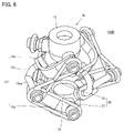
- FIG. 6 is a perspective view of the spherical link actuator 100B.
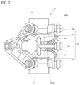
- FIG. 7 is a front view of the spherical link actuator 100B.
- the spherical link actuator 100B has a spherical link mechanism 10, a plurality of drive sources 20 (not shown in FIGS. 6 and 7), and a plurality of string members 30.
- the configuration of the spherical link actuation device 100B is in common with the configuration of the spherical link actuation device 100. As shown in FIG.
- the configuration of the spherical link actuating device 100B differs from the configuration of the spherical link actuating device 100 with respect to the details of the intermediate link member 13c and the string member 30.
- the intermediate link member 13c has a relay portion 13ca.
- the relay portion 13ca extends in a direction parallel to the first rotation axis and the second rotation axis when the spherical link mechanism 10 is in the origin posture.
- the spherical link mechanism 10 assumes the origin posture when the first central axis and the second central axis are on the same straight line.
- the relay portion 13ca is located between one end and the other end of the intermediate link member 13c. That is, the relay portion 13ca overlaps with the intermediate plane of the spherical link mechanism 10 .
- the string-like member 30 has a first portion 31 and a second portion 32 .
- the first portion 31 and the second portion are, for example, annular string-like members independent of each other.
- the first portion 31 connects one end of the base end link member 13a and the relay portion 13ca
- the second portion 32 connects one end of the tip link member 13b and the relay portion 13ca. is connected with
- the second portion 32 is twisted once (figure 8) so that the rotation of the base end link member 13a about the first rotation axis and the rotation of the tip link member 13b about the second rotation axis are reversed.
- one end of the base end link member 13a and the relay portion 13ca are connected.
- each of the plurality of cord-like members 30 is relayed by the relay portion 13ca in each of the plurality of links 13, and then connects one end of the proximal end link member 13a and one end of the distal end link member 13b. are doing.
- each of the plurality of string-like members 30 rotates the base end link member 13a and the tip end link member 13b of each of the plurality of links 13 around the first rotation axis and the second rotation axis, respectively. rotate at the same time.
- the one end of the base end link member 13a and the relay portion 13ca are connected while the second portion 32 is twisted once, the direction of rotation of the base end link member 13a about the first rotation axis is changed.
- FIG. 8 is a perspective view of the spherical link actuating device 100B showing all of the string-like members 30 without omitting them.
- the string member 30 further has a third portion 33.
- the third portion 33 is an annular string-like member and is independent of the first portion 31 and the second portion 32 .
- the third portion 33 connects one end of the base end link member 13a and the drive source 20 (not shown in FIG. 8). Therefore, in the spherical link actuator 100B, the power of the drive source 20 is transmitted by the third portion 33 to rotate the base end link member 13a in the forward direction, and the forward rotation of the base end link member 13a is caused by the first portion 31.
- the forward rotation of the relay portion 13ca is reversed by the second portion 32, and the tip link member 13b is rotated in the reverse direction.
- ⁇ Effect of spherical link actuator 100B> the base end link member 13a of each of the plurality of links 13 is rotated around the first rotation axis, or the tip link member 13b of each of the plurality of links 13 is rotated around the second rotation axis. Thereby, the position and posture of the distal end link hub 12 with respect to the proximal end link hub 11 can be changed. From another point of view, in order to change the position and attitude of the distal link hub 12 with respect to the proximal link hub 11, the proximal link member 13a and the distal link member 13b of each of the plurality of links 13 are respectively moved to the second position. It is not necessary to rotate about one axis of rotation and about a second axis of rotation at the same time.
- the base end link hub 11 side of the spherical link mechanism 10 always moves symmetrically with the distal end link hub 12 side of the spherical link mechanism 10 with respect to the intermediate plane. That is, when the spherical link mechanism 10 performs an ideal operation, the direction of rotation of the base end link member 13a around the first rotation axis is opposite to the direction of rotation of the tip link member 13b around the second rotation axis, The amount of rotation of the base end link member 13a around the first rotation axis is the same as the amount of rotation of the tip link member 13b around the second rotation axis.
- the spherical link mechanism 10 is not ideal due to the backlash of the rotational pair of the link 13, the time difference between the power transmission between the proximal end and the distal end, the backlash of each member constituting the spherical link mechanism 10, and the like. It may deviate from normal behavior.
- the string-like member 30 causes the proximal end link member 13a and the distal end link member 13b to rotate simultaneously about the first rotation axis and the second rotation axis, respectively. Further, in the spherical link actuator 100B, at this time, the direction of rotation of the base end link member 13a around the first rotation axis is opposite to the direction of rotation of the tip end link member 13b around the second rotation axis. The amount of rotation of the member 13a around the first rotation axis is the same as the amount of rotation of the tip link member 13b around the second rotation axis.
- the movement of the spherical link mechanism 10 is corrected to a near-ideal operation by reducing the backlash of the rotating pair of the link 13 and reducing the time difference in power transmission between the proximal side and the distal side. Therefore, the accuracy of determination of the position and attitude of the distal end link hub 12 with respect to the proximal end link hub 11 is improved, and vibration is reduced.
- a spherical link actuation device (referred to as a “spherical link actuation device 100C”) according to the fourth embodiment will be described.
- spherical link actuation device 100C A spherical link actuation device according to the fourth embodiment will be described.
- differences from the spherical link actuation device 100 will be mainly described, and redundant description will not be repeated.
- FIG. 9 is a perspective view of the spherical link actuator 100C.
- FIG. 10 is a perspective view of the pulley 50 included in the spherical link actuator 100C.
- the spherical link actuator 100C has a spherical link mechanism 10, multiple drive sources 20, and multiple cord-like members 30.
- the configuration of the spherical link actuation device 100C is common to the configuration of the spherical link actuation device 100. As shown in FIG.
- the spherical link actuator 100C further has a plurality of pulleys 50.
- the pulley 50 has a pulley 51 , a pulley shaft member 52 , a support portion 53 and a pulley fixed shaft member 54 .
- the pulley 51 is attached to the pulley shaft member 52 .
- the pulley 51 is rotatable around the central axis of the pulley shaft member 52 .
- the pulley 51 relays the string member 30 between the drive source 20 and the intermediate link member 13c.
- the pulley shaft member 52 is attached to the support portion 53 .
- the pulley 51 may be rotatable about the central axis of the pulley shaft member 52 by rotating with respect to the pulley shaft member 52 , and the pulley shaft member 51 may be rotated with respect to the support portion 53 .
- 52 may be rotatable around the central axis.
- the support portion 53 is attached to the pulley fixed shaft member 54 .
- the pulley 50 is attached to the base end link hub 11 by a pulley fixing shaft member 54 .
- the pulley 50 may be attached to a base on which the proximal link hub 11 is placed by a pulley fixing shaft member 54 .
- the pulley fixed shaft member 54 is preferably rotatable around the central axis of the pulley fixed shaft member 54 .
- the pulley 51 is rotatable about the central axis of the pulley fixed shaft member 54 with one rotational degree of freedom.
- the pulley 51 may be rotatable around the central axis of the pulley fixed shaft member 54 by allowing the support portion 53 to rotate around the central axis of the pulley fixed shaft member 54 .
- the central axis of the pulley fixed shaft member 54 preferably passes through the first spherical link central point.
- the intermediate link member 13c has a hook portion 13cb.
- One end of the string-like member 30 (the end opposite to the drive source 20) is hooked on the hook portion 13cb, thereby connecting the string-like member 30 to the intermediate link member 13c.
- the method of connecting the string member 30 to the intermediate link member 13c is not limited to this.
- the configuration of the spherical link actuator 100C differs from the configuration of the spherical link actuator 100 in these respects.
- a spherical link actuation device (referred to as a “spherical link actuation device 100D”) according to the fifth embodiment will be described.
- differences from the spherical link actuation device 100C will be mainly described, and redundant description will not be repeated.
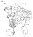
- FIG. 11 is a perspective view of the spherical link actuator 100D.
- FIG. 12 is a front view of the spherical link actuator 100D. 12, one of the plurality of links 13, one of the plurality of drive sources 20, one of the plurality of string members 30, and one of the plurality of pulleys 50 are shown. One of the pulleys 60 is shown.
- the spherical link actuator 100D has a spherical link mechanism 10, a plurality of drive sources 20, a plurality of string members 30, and a plurality of pulleys 50.
- the configuration of the spherical link actuation device 100D is common to the configuration of the spherical link actuation device 100C.
- the spherical link actuator 100D further has a plurality of pulleys 60.
- the pulley 60 has a pulley 61 , a pulley shaft member 62 , a support portion 63 and a pulley fixed shaft member 64 .
- the pulley 61 is attached to the pulley shaft member 62 .
- the pulley 61 is rotatable around the central axis of the pulley shaft member 62 .
- the string member 30 connects the drive source 20 and the tip link hub 12 .
- the pulleys 51 and 61 relay the string-like member 30 between the drive source 20 and the tip link hub 12 .
- the pulley shaft member 62 is attached to the support portion 63 .
- the pulley 61 may be rotatable about the central axis of the pulley shaft member 62 by rotating with respect to the pulley shaft member 62 , and the pulley shaft member 61 may be rotated with respect to the support portion 63 .
- 62 may be rotatable around the central axis.
- the support portion 63 is attached to the pulley fixed shaft member 64 .
- the pulley 60 is attached to the intermediate link member 13 c by a pulley fixing shaft member 64 . More specifically, the pulley 60 is attached to the intermediate link member 13c such that the pulley 61 is outside the intermediate link member 13c.
- the pulley fixed shaft member 64 cannot rotate with respect to the intermediate link member 13c. Therefore, the pulley 61 cannot rotate with respect to the intermediate link member 13c.
- the tip link hub 12 has a hook portion 12a.
- the string-like member 30 is connected to the tip link hub 12 by hooking one end of the string-like member 30 (the end opposite to the drive source 20) on the hook portion 12a.
- the method of connecting the string member 30 to the tip link hub 12 is not limited to this.
- the configuration of the spherical link actuator 100D differs from the configuration of the spherical link actuator 100C.
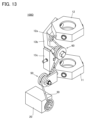
- FIG. 13 is a perspective view of a spherical link actuator 100D according to a modification. 13, one of the plurality of links 13, one of the plurality of drive sources 20, one of the plurality of string members 30, and one of the plurality of pulleys 50 are shown. One of the pulleys 60 is shown. As shown in FIG. 13, the pulley 61 (pulley 60) may be inside the intermediate link member 13c. Although not shown, the pulley 50 may be omitted in the spherical link actuator 100D. In this case, the string-like member 30 is relayed only by the pulley 61 between the tip link hub 12 and the drive source 20 .
- the string-like member 30 is relayed by the pulleys 51 and 61 , the string-like member 30 is less likely to interfere with the spherical link mechanism 10 .
- the pulley 60 (pulley 61) is outside the intermediate link member 13c, the string-like member 30 is less likely to interfere with the spherical link mechanism 10.
- the pulley 60 (pulley 61) is inside the intermediate link member 13c, it is possible to downsize the spherical link actuator 100D.
- a spherical link actuation device (referred to as a “spherical link actuation device 100E”) according to the sixth embodiment will be described.
- differences from the spherical link actuation device 100C will be mainly described, and redundant description will not be repeated.
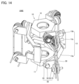
- FIG. 14 is a perspective view of the spherical link actuator 100E.
- FIG. 15 is a perspective view of the drive converting portion 70 included in the spherical link actuator 100E. 15, the tip link hub 12 and one tip link member 13b of the plurality of links 13 are shown together with the drive converter 70.
- the spherical link actuator 100E includes a spherical link mechanism 10, a plurality of drive sources 20 (not shown in FIG. 14), a plurality of cord-like members 30, and a plurality of A pulley 50 is provided.
- the configuration of the spherical link actuation device 100E is common to the configuration of the spherical link actuation device 100C.
- the spherical link actuator 100E further has a plurality of drive conversion parts 70.
- the drive conversion section 70 has a pulley 71 , a pulley shaft member 72 , a support section 73 , a gear 74 , a gear 75 , and a gear fixing shaft member 76 .
- the pulley 50 is attached to the base end link hub 11 so that the central axis of the pulley fixed shaft member 54 coincides with the first rotation axis.
- the pulley 71 is attached to the pulley shaft member 72 .
- the pulley 71 is rotatable around the central axis of the pulley shaft member 72 .
- the central axis of the pulley shaft member 72 is orthogonal to the central axis of the gear fixing shaft member 76 .
- the string member 30 connects the drive source 20 and the pulley 71 . Therefore, the pulley 71 is rotated around the central axis of the pulley shaft member 72 by the drive source 20 and the string member 30 .
- the pulley 51 Since the string-like member 30 is relayed by the pulley 51 between the drive source 20 and the pulley 71, the pulley 51 is rotated around the central axis of the pulley shaft member 52 by the drive source 20 and the string-like member 30. .
- the pulley shaft member 72 is attached to the support portion 73 .
- the pulley 71 may be rotatable about the central axis of the pulley shaft member 72 by rotating with respect to the pulley shaft member 72 , and the pulley shaft member 71 may be rotated with respect to the support portion 73 . It may be rotatable around the central axis of 72 .
- the gear 74 is fixed to the pulley 71. Therefore, the gear 74 can rotate around the central axis of the pulley shaft member 72 together with the pulley 71 .
- the gear 75 is fixed to a gear fixing shaft member 76 . By transmitting the rotational force of the gear 74 to the gear 75 , the gear 75 is rotated around the central axis of the gear fixing shaft member 76 .
- a central axis of the gear fixing shaft member 76 extends along the second rotation axis.
- the gear fixing shaft member 76 is connected to the tip link hub 12 so as to be rotatable around the second rotation axis.
- the gear fixing shaft member 76 is fixed to one end of the tip link member 13b. Therefore, the torque of the gear 74 is transmitted to the gear 75 so that the gear 75 rotates around the second rotation axis together with the tip link member 13b and the gear fixing shaft member 76 .
- the gears 74 and 75 are, for example, bevel gears. However, the gears 74 and 75 are not limited to this, and are not particularly limited as long as the rotational force of the gear 74 can be transmitted to the gear 75 after rotating the rotation direction by 90°.
- the gears 74 and 75 magnetic gears, helical gears, etc. can be used in addition to bevel gears.
- the number of teeth of the gear 74 and the number of teeth of the gear 75 may be equal or different.
- the support portion 73 is attached to the gear fixing shaft member 76 .
- the support portion 73 is rotatable around the central axis of the gear fixing shaft member 76, that is, around the second rotation axis, independently of the gear fixing shaft member 76.
- the pulley 71 attached to the support portion 53 via the pulley shaft member 72 and the gear 74 fixed to the pulley 71 are also rotatable around the second rotation axis independently of the gear fixing shaft member 76.
- Pulleys 51 and 71 are preferably parallel regardless of the orientation of distal link hub 12 with respect to proximal link hub 11 . More preferably, pulley 51 and pulley 71 are on the same plane regardless of the orientation of distal link hub 12 with respect to proximal link hub 11 .
- the distance between the pulleys 51 and 71 changes according to the attitude of the distal end link hub 12 with respect to the proximal end link hub 11 .
- the spherical link actuator 100E has a plurality of tension adjustment functions (not shown) that can adjust the tension of the string-like member 30 between the pulleys 51 and 71 according to the distance between the pulleys 51 and 71. It is preferable to further have Each of the plurality of tension adjustment mechanisms is attached to each of the plurality of string members 30 .
- a tension adjustment mechanism is, for example, a tensioner.
- the configuration of the spherical link actuator 100E differs from the configuration of the spherical link actuator 100C.
- the attitude control of the distal end link hub 12 with respect to the proximal end link hub 11 is performed at a position close to the distal end link hub 12, and the attitude control of the distal end link hub 12 with respect to the proximal end link hub 11 is performed. Increased accuracy.
- the pulley 51 is rotatable around the central axis (first rotational axis) of the pulley fixed shaft member 54
- the pulley 71 is rotatable around the central axis (second rotational axis) of the gear fixed shaft member 76. )
- the pulleys 51 and 71 are parallel (or the pulleys 51 and 71 are on the same plane) regardless of the attitude of the distal link hub 12 with respect to the proximal link hub 11. above) can be maintained.
Landscapes
- Engineering & Computer Science (AREA)
- General Engineering & Computer Science (AREA)
- Mechanical Engineering (AREA)
- Robotics (AREA)
- Transmission Devices (AREA)
- Manipulator (AREA)
Abstract
球面リンク作動装置は、球面リンク機構(10)と、複数の紐状部材(30)と、複数の駆動源(40)とを備える。球面リンク機構は、基端リンクハブ(11)と、先端リンクハブ(12)と、基端リンクハブ及び先端リンクハブを連結している複数のリンク(13)とを有する。複数のリンクの各々は、基端リンク部材(13a)と、先端リンク部材(13b)と、中間リンク部材(13c)とを含む。基端リンク部材は、基端リンク部材の一方端において第1回転軸回りに回転可能に基端リンクハブに連結されている。先端リンク部材は、先端リンク部材の一方端において第2回転軸回りに回転可能に先端リンクハブに連結されている。中間リンク部材は、中間リンク部材の一方端において基端リンク部材の他方端に第3回転軸回りに回転可能に連結されているとともに、中間リンク部材の他方端において先端リンク部材の他方端に第4回転軸回りに回転可能に連結されている。
Description
本発明は、球面リンク作動装置に関する。
特許第6289973号公報(特許文献1)には、リンク作動装置が記載されている。特許文献1に記載のリンク作動装置は、球面リンク機構と、複数の姿勢変更用アクチュエータとを有している。
球面リンク機構は、基端リンクハブと、先端リンクハブと、複数のリンクとを有している。複数のリンクは、基端リンクハブと先端リンクハブとを連結している。複数のリンクの各々は、基端リンク部材と、先端リンク部材と、中間リンク部材とを有している。
基端リンク部材は、基端リンク部材の一方端において、第1回転軸回りに回転可能に基端リンクハブに連結されている。先端リンク部材は、先端リンク部材の一方端において、第2回転軸回りに回転可能に先端リンクハブに連結されている。中間リンク部材は、中間リンク部材の一方端において第3回転軸回りに回転可能に基端リンク部材の他方端に連結されているとともに、中間リンク部材の他方端において第4回転軸回りに回転可能に先端リンク部材の他方端に連結されている。
基端リンクハブの中心軸、第1回転軸及び第3回転軸は、1点で交わっている。この1点を、第1球面リンク中心点とする。先端リンクハブの中心軸、第2回転軸及び第4回転軸は、第1球面リンク中心点とは別の1点で交わっている。この別の1点を、第2球面リンク中心点とする。基端リンクハブは、第1球面リンク中心点を中心とする球面上を移動する。先端リンクハブは、第2球面リンク中心点を中心とする球面上を移動する。すなわち、球面リンク機構は、2つの球面リンク機構が組み合わされて構成されている。
特許文献1に記載のリンク作動装置では、複数の姿勢変更用アクチュエータの各々が複数のリンクの各々の基端リンク部材を第1回転軸回りに回転させることにより、先端リンクハブの基端リンクハブに対する位置及び姿勢が変更される。
特許文献1に記載のリンク作動装置では、複数のリンクの各々の基端リンク部材を第1回転軸回りに回転させるため、複数の姿勢変更用アクチュエータを基端リンクハブの周囲に放射状に配置せざるを得ない。すなわち、複数のリンク作動装置では、複数の姿勢変更用アクチュエータの配置に制約が大きい。
本発明は、上記のような従来技術の問題点に鑑みてなされたものである。より具体的には、本発明は、駆動源の配置の自由度を高めることが可能な球面リンク作動装置を提供するものである。
本発明の球面リンク作動装置は、球面リンク機構と、複数の紐状部材と、複数の駆動源とを備える。球面リンク機構は、基端リンクハブと、先端リンクハブと、基端リンクハブ及び先端リンクハブを連結している複数のリンクとを有する。複数のリンクの各々は、基端リンク部材と、先端リンク部材と、中間リンク部材とを含む。基端リンク部材は、基端リンク部材の一方端において、第1回転軸回りに回転可能に基端リンクハブに連結されている。先端リンク部材は、先端リンク部材の一方端において、第2回転軸回りに回転可能に先端リンクハブに連結されている。中間リンク部材は、中間リンク部材の一方端において基端リンク部材の他方端に第3回転軸回りに回転可能に連結されているとともに、中間リンク部材の他方端において先端リンク部材の他方端に第4回転軸回りに回転可能に連結されている。基端リンクハブの中心軸、第1回転軸及び第3回転軸は、第1球面リンク中心点において交わっている。先端リンクハブの中心軸、第2回転軸及び第4回転軸は、第2球面リンク中心点において交わっている。基端リンクハブ及び先端リンクハブは、それぞれ、第1球面リンク中心点を中心とする第1移動球面上及び第2球面リンク中心点を中心とする第2移動球面上を移動する。複数の紐状部材の各々は、複数の駆動源の各々と球面リンク機構とに連結されている。複数の駆動源の各々の動力が複数の紐状部材の各々を介して球面リンク機構に伝達されることにより、基端リンクハブに対する先端リンクハブの位置及び姿勢が変化される。
上記の球面リンク作動装置では、複数の駆動源の各々が、複数の紐状部材の各々に加わる張力を調整することにより、基端リンクハブに対する先端リンクハブの位置及び姿勢を変化させてもよい。
上記の球面リンク作動装置では、複数の紐状部材の各々は、複数のリンクの各々の中間リンク部材と複数の駆動源の各々とを連結していてもよい。
上記の球面リンク作動装置は、基端リンクハブに取り付けられている複数の滑車をさらに備えていてもよい。複数の滑車の各々は、プーリと滑車固定軸部材とを有し、かつ滑車固定軸部材により基端リンクハブに取り付けられていてもよい。複数の紐状部材の各々は、複数の滑車の各々のプーリにより中継されていてもよい。
上記の球面リンク作動装置では、複数の滑車の各々において、プーリが、滑車固定軸部材の中心軸回りに回転1自由度で回転可能であってもよい。
上記の球面リンク作動装置では、複数の滑車の各々において、滑車固定軸部材の中心軸が、第1球面リンク中心点を通っていてもよい。
上記の球面リンク作動装置は、複数の第1滑車及び複数の第2滑車をさらに備えていてもよい。複数の紐状部材の各々は、先端リンクハブと複数の駆動源の各々とを連結していてもよい。複数の第1滑車の各々は、第1プーリと第1滑車固定軸部材とを有し、かつ、第1滑車固定軸部材により基端リンクハブに取り付けられていてもよい。複数の第2滑車の各々は、第2プーリと第2滑車固定軸部材とを有し、かつ、第2滑車固定軸部材により複数のリンクの各々の中間リンク部材に取り付けられていてもよい。複数の紐状部材の各々は、複数の第1滑車の各々の第1プーリ及び複数の第2滑車の各々の第2プーリにより中継されていてもよい。
上記の球面リンク作動装置では、複数の第1滑車の各々において、第1プーリが、第1滑車固定軸部材の中心軸回りに回転1自由度で回転可能であってもよい。複数の第2滑車の各々は、複数のリンクの各々の中間リンク部材に対して回転不能であってもよい。
上記の球面リンク作動装置では、複数の第2滑車の各々の第2プーリが、複数のリンクの各々の中間リンク部材の外側に位置していてもよい。
上記の球面リンク作動装置では、複数の第2滑車の各々の第2プーリが、複数のリンクの各々の中間リンク部材の内側に位置していてもよい。
上記の球面リンク作動装置では、複数の紐状部材の各々が、先端リンクハブ又は複数のリンクの各々の先端リンク部材と複数の駆動源の各々とを連結していてもよい。
上記の球面リンク作動装置では、複数の駆動源の各々が、プーリを有していてもよい。複数の駆動源の各々は、プーリを回転させて複数の紐状部材の各々を巻き取る又は繰り出すことにより、複数の紐状部材の各々に加わる張力を調整してもよい。
上記の球面リンク作動装置は、複数のセンサをさらに備えていてもよい。複数のセンサの各々は、複数の駆動源の各々のプーリによる複数の紐状部材の各々の巻き取り量又は繰り出し量を検知可能に構成されていてもよい。上記の球面リンク作動装置では、複数の紐状部材が、複数のワイヤ、複数の糸、複数の鎖又は複数のベルトであってもよい。
上記の球面リンク作動装置は、複数のテンショナをさらに備えていてもよい。複数のテンショナの各々は、複数の紐状部材の各々に加わる張力を調整可能に構成されていてもよい。
上記の球面リンク作動装置では、複数の駆動源の各々が、複数の紐状部材の各々を介して複数のリンクの各々の基端リンク部材を第1回転軸回りに回転させることにより、先端リンクハブの位置及び姿勢が変化させてもよい。
上記の球面リンク作動装置では、複数の紐状部材が、複数の環状のタイミングベルトであってもよい。複数の駆動源の各々は、タイミングプーリを有していてもよい。複数のリンクの各々の基端リンク部材及び複数の駆動源の各々のタイミングプーリは、複数の環状のタイミングベルトの各々により連結されていてもよい。
上記の球面リンク作動装置は、複数の滑車と、複数の駆動変換部とをさらに備えていてもよい。複数の滑車の各々は、第1プーリと滑車固定軸部材とを有し、かつ滑車固定軸部材により基端リンクハブに取り付けられていてもよい。複数の滑車の各々において、第1プーリは、滑車固定軸部材の中心軸回りに回転1自由度で回転可能であってもよい。複数の駆動変換部の各々は、支持部と、支持部に取り付けられている第2プーリと、第2プーリとともに回転する第1歯車と、第1歯車の回転力が伝達される第2歯車と、第2歯車に固定されている歯車固定軸部材とを有していてもよい。複数の紐状部材の各々は、複数の滑車の各々の第1プーリに中継されて複数の駆動源の各々の第2プーリと複数の駆動源の各々とを連結していてもよい。複数の駆動変換部の各々の歯車固定軸部材は、複数のリンクの各々の先端リンク部材の一方端に固定されており、かつ第2回転軸回りに回転可能に先端リンクハブに連結されていてもよい。複数の駆動変換部の各々において、支持部は、歯車固定軸部材から独立して第2回転軸回りに回転可能であってもよい。
上記の球面リンク作動装置では、複数の滑車の各々の第1プーリが、複数の駆動変換部の各々の第2プーリと同一平面上に配置されていてもよい。
上記の球面リンク作動装置は、複数の張力調整機構をさらに備えていてもよい。複数の張力調整機構の各々は、複数の滑車の各々の第1プーリと複数の駆動源の各々の第2プーリとの間にある複数の紐状部材の各々に加わる張力を調整可能に構成されていてもよい。
上記の球面リンク作動装置では、複数の駆動源の各々が、複数の紐状部材の各々を介して複数のリンクの各々の基端リンク部材及び先端リンク部材をそれぞれ第1回転軸回り及び第2回転軸回りに同時に回転させてもよい。複数のリンクの各々において、基端リンク部材の第1回転軸回りの回転方向が先端リンク部材の第2回転軸回りの回転方向と逆になるとともに、基端リンク部材の第1回転軸回りの回転量が先端リンク部材の第2回転軸回りの回転量と同一になってもよい。
上記の球面リンク作動装置では、複数の紐状部材の各々が、複数のリンクの各々において、中間リンク部材で中継された上で、基端リンク部材及び先端リンク部材に連結されていてもよい。
本発明の球面リンク作動装置によると、駆動源の配置の自由度を高めることが可能である。
本発明の実施形態の詳細を、図面を参照しながら説明する。以下の図面では、同一又は相当する部分に同一の参照符号を付し、重複する説明は繰り返さないものとする。
(第1実施形態)
以下に、第1実施形態に係る球面リンク作動装置(「球面リンク作動装置100」とする)を説明する。
以下に、第1実施形態に係る球面リンク作動装置(「球面リンク作動装置100」とする)を説明する。
<球面リンク作動装置100の構成>
図1は、球面リンク作動装置100の斜視図である。図2は、球面リンク作動装置100の正面図である。図1及び図2に示されるように、球面リンク作動装置100は、球面リンク機構10と、複数の駆動源20と、複数の紐状部材30とを有している。
図1は、球面リンク作動装置100の斜視図である。図2は、球面リンク作動装置100の正面図である。図1及び図2に示されるように、球面リンク作動装置100は、球面リンク機構10と、複数の駆動源20と、複数の紐状部材30とを有している。
球面リンク機構10は、基端リンクハブ11と、先端リンクハブ12と、複数のリンク13とを有している。基端リンクハブ11及び先端リンクハブ12は、複数のリンク13により連結されている。基端リンクハブ11の中心軸を、第1中心軸とする。先端リンクハブ12の中心軸を、第2中心軸とする。
複数のリンク13の数は、例えば3つである。但し、複数のリンク13の数は、2つであってもよく、4つ以上であってもよい。以下においては、複数のリンク13の数が3つである場合を例として説明する。複数のリンク13は、例えば等間隔で配置されている。複数のリンク13が等間隔で配置されている場合、球面リンク機構10としての計算が行いやすい。なお、複数のリンク13は、等間隔で配置されていなくてもよい。
リンク13は、基端リンク部材13aと、先端リンク部材13bと、中間リンク部材13cとを有している。基端リンク部材13a及び先端リンク部材13bは、例えば、L字形状になっている。中間リンク部材13cは、例えば、円弧形状になっている。
基端リンク部材13aは、基端リンク部材13aの一方端において、第1回転軸回りに回転可能に基端リンクハブ11に連結されている。基端リンク部材13aの基端リンクハブ11に対する回転に伴う摩擦は、回転抵抗低減部材により低減されてもよい。この回転抵抗低減部材は、例えば転がり軸受又は滑り軸受である。
先端リンク部材13bは、先端リンク部材13bの一方端において、第2回転軸回りに回転可能に先端リンクハブ12に連結されている。先端リンク部材13bの先端リンクハブ12に対する回転に伴う摩擦は、回転抵抗低減部材により低減されてもよい。この回転抵抗低減部材は、例えば転がり軸受又は滑り軸受である。
中間リンク部材13cは、中間リンク部材13cの一方端において、第3回転軸回りに回転可能に基端リンク部材13aの他方端に連結されている。中間リンク部材13cは、中間リンク部材13cの他方端において、第4回転軸回りに回転可能に先端リンク部材13bの他方端に連結されている。
中間リンク部材13cの基端リンク部材13aに対する回転に伴う摩擦及び中間リンク部材13cの先端リンク部材13bに対する回転に伴う摩擦は、回転抵抗低減部材により低減されてもよい。この回転抵抗低減部材は、例えば転がり軸受又は滑り軸受である。
第1中心軸、第1回転軸及び第3回転軸は、1点で交わっている。この1点を、第1球面リンク中心点とする。第2中心軸、第2回転軸及び第4回転軸は、第1球面リンク中心点とは別の1点で交わっている。この別の1点を、第2球面リンク中心点とする。第1球面リンク中心点と第2球面リンク中心点との間の距離は、先端リンクハブ12の基端リンクハブ11に対する位置及び姿勢によらず、一定となる。
基端リンクハブ11は、第1球面リンク中心点を中心とする球面上を移動する。この球面を、第1移動球面とする。先端リンクハブ12は、第2球面リンク中心点を中心とする球面上を移動する。この球面を、第2移動球面とする。球面リンク機構10は、2つの球面リンク機構が組み合わされた構造になっている。
第1移動球面と第2移動球面とが交わっている面を、中間平面とする。球面リンク機構10の基端リンクハブ11側(中間平面よりも基端リンクハブ11側にある球面リンク機構10の部分)は、中間平面に関して、球面リンク機構10の先端リンクハブ12側(中間平面よりも先端リンクハブ12側にある球面リンク機構10の部分)と常に対称になるように動く。
複数の駆動源20の数は、例えば3つである。但し、複数の駆動源20の数は、2つであってもよく、4つ以上であってもよい。以下においては、複数の駆動源20の数が3つである場合を例として説明する。
駆動源20は、本体部21(図1及び図2において図示せず)と、軸体22とを有している。本体部21は、軸体22をその中心軸回りに回転させる。本体部21は、ケース40の内部に収納されている。軸体22は、ケース40の外部にある。駆動源20は、例えば、モータである。球面リンク機構10は、ケース40上に配置されている。
複数の紐状部材30の数は、複数のリンク13の数に等しい。また、複数の紐状部材30の数は、複数の駆動源20の数に等しい。紐状部材30は、駆動源20と球面リンク機構10とを連結している。より具体的には、紐状部材30は、軸体22と中間リンク部材13cとを連結している。紐状部材30は、軸体22と先端リンクハブ12とを連結していてもよい。紐状部材30は、軸体22と基端リンク部材13a又は先端リンク部材13bとを連結していてもよい。
紐状部材30は、軸体22に取り付けられているプーリと先端リンクハブ12、基端リンク部材13a、先端リンク部材13b及び中間リンク部材13cのいずれかとを連結していてもよい。紐状部材30は、例えば、ワイヤである。但し、紐状部材30は、糸、鎖又はベルトであってもよい。
複数の駆動源20の各々は、複数の紐状部材30の各々を介して球面リンク機構10に動力を伝達することにより、先端リンクハブ12の基端リンクハブ11に対する位置及び姿勢が変更される。より具体的には、複数の駆動源20の各々は、複数の紐状部材30の各々に加わる張力を調整する。これにより、複数の紐状部材30の各々に加わる張力の釣り合う位置が変化し、先端リンクハブ12の基端リンクハブ11に対する位置及び姿勢が変更される。
紐状部材30は、本体部21が軸体22を回転させることにより、軸体22に巻き取られる。紐状部材30は、本体部21が回転軸を逆回転させることにより、軸体22から繰り出される。これにより、紐状部材30に加わる張力が調整される。
球面リンク作動装置100は、複数のセンサを有していてもよい。複数のセンサの各々は、複数の駆動源20の各々における紐状部材30の巻き取り量及び繰り出し量を検知可能に構成されている。複数の駆動源20の各々は、センサにより検知された紐状部材30の巻き取り量及び繰り出し量に基づいて、先端リンクハブ12の基端リンクハブ11に対する位置及び姿勢を制御してもよい。
球面リンク作動装置100は、複数のテンショナを有していてもよい。複数のテンショナの各々は、複数の紐状部材30の各々の近傍に配置されている。テンショナを紐状部材30に接触させることにより紐状部材30に加わる張力が常に適切に維持される。
<球面リンク作動装置100の効果>
球面リンク作動装置100では、球面リンク機構10に複数の駆動源20からの動力が複数の紐状部材30を介して伝達されることにより、先端リンクハブ12の基端リンクハブ11に対する位置及び姿勢が変更される。球面リンク機構10と駆動源20とは、紐状部材30を介して連結されているため、駆動源20の配置は、紐状部材30の長さを変えることにより、容易に変更することができる。このように、球面リンク作動装置100によると、駆動源20の配置の自由度を高めることが可能である。
球面リンク作動装置100では、球面リンク機構10に複数の駆動源20からの動力が複数の紐状部材30を介して伝達されることにより、先端リンクハブ12の基端リンクハブ11に対する位置及び姿勢が変更される。球面リンク機構10と駆動源20とは、紐状部材30を介して連結されているため、駆動源20の配置は、紐状部材30の長さを変えることにより、容易に変更することができる。このように、球面リンク作動装置100によると、駆動源20の配置の自由度を高めることが可能である。
例えば、球面リンク作動装置100を他の装置のエンドエフェクタとして用いる場合、球面リンク機構10から離れた位置に駆動源20を配置することにより、当該他の装置は球面リンク機構10のみを移動させればよいため、エンドエフェクタとしての重量ないし慣性モーメントを小さくすることができる。
紐状部材30としてワイヤ、糸及び鎖のいずれかが用いられる場合、先端リンクハブ12の基端リンクハブ11に対する位置及び姿勢の変更に伴って紐状部材30にねじれが生じたとしても、紐状部材30を介した動力の伝達が可能である。紐状部材30としてベルトが用いられる場合、紐状部材30の切断、滑り及び脱落を抑制することができる。
紐状部材30が先端リンクハブ12又は先端リンク部材13bに連結されている場合、先端リンクハブ12の近くで先端リンクハブ12の基端リンクハブ11に対する位置及び姿勢を制御することができるため、リンク13の遊び(ガタ)に起因した先端リンクハブ12の基端リンクハブ11に対する位置及び姿勢の決定の精度の低下が抑制される。
紐状部材30が中間リンク部材13cに連結されている場合、中間リンク部材13cはリンク13の最も外側にあるため、紐状部材30がリンク13と干渉することが抑制される。紐状部材30が基端リンク部材13aに連結されている場合、紐状部材30を短くすることができる。また、この場合、球面リンク機構10の内部に紐状部材30が入らないため、紐状部材30と球面リンク機構10との干渉を抑制することができる。
軸体22に取り付けられたプーリにより紐状部材30の巻き取り及び繰り出しが行われる場合、紐状部材30の摩耗・摩擦を減らすことができる。また、この場合、紐状部材30の脱落が防止される。さらに、この場合、プーリの径を変更することにより、紐状部材30の巻き取り及び繰り出しを増速又は減速することができる。
球面リンク作動装置100が複数のテンショナを有する場合、滑り損失の低減に伴い、紐状部材30を介した動力の伝達効率が改善される。また、この場合、リンク13のガタつきを抑制することができる。球面リンク作動装置100が複数のセンサを有し、これらの出力に基づいて先端リンクハブ12の基端リンクハブ11に対する位置及び姿勢の制御が行われる場合、より正確に先端リンクハブ12の基端リンクハブ11に対する位置及び姿勢を決定することができる。
(第2実施形態)
第2実施形態に係る球面リンク作動装置(「球面リンク作動装置100A」とする)を説明する。ここでは、球面リンク作動装置100と異なる点を主に説明し、重複する説明は繰り返さないものとする。
第2実施形態に係る球面リンク作動装置(「球面リンク作動装置100A」とする)を説明する。ここでは、球面リンク作動装置100と異なる点を主に説明し、重複する説明は繰り返さないものとする。
<球面リンク作動装置100Aの構成>
図3は、球面リンク作動装置100Aの斜視図である。図4は、球面リンク作動装置100Aの正面図である。球面リンク作動装置100Aは、球面リンク機構10と、複数の駆動源20と、複数の紐状部材30とを有している。この点に関して、球面リンク作動装置100Aの構成は、球面リンク作動装置100の構成と共通している。
図3は、球面リンク作動装置100Aの斜視図である。図4は、球面リンク作動装置100Aの正面図である。球面リンク作動装置100Aは、球面リンク機構10と、複数の駆動源20と、複数の紐状部材30とを有している。この点に関して、球面リンク作動装置100Aの構成は、球面リンク作動装置100の構成と共通している。
しかしながら、球面リンク作動装置100Aの構成は、駆動源20及び紐状部材30の詳細に関して、球面リンク作動装置100の構成と異なっている。
球面リンク作動装置100Aでは、複数の駆動源20の各々の本体部21が、重ねて配置されている。また、球面リンク作動装置100Aでは、複数の駆動源20の各々の軸体22が、複数のリンク13の各々の第1回転軸と平行になるように配置されている。
球面リンク作動装置100Aでは、軸体22にタイミングプーリ23が取り付けられている。球面リンク作動装置100Aでは、複数の紐状部材30が、例えば複数の環状のタイミングベルトである。複数の環状のタイミングベルトの各々は、複数の駆動源20の各々のタイミングプーリ23と複数のリンク13の各々の基端リンク部材13aとに連結されている。そのため、複数の駆動源20の各々のタイミングプーリ23を回転させることにより、複数のリンク13の各々の基端リンク部材13aが第1中心軸回りに回転され、先端リンクハブ12の基端リンクハブ11に対する位置及び姿勢が変更される。
<球面リンク作動装置100Aの効果>
球面リンク作動装置100Aでは、複数のリンク13の各々の基端リンク部材13aを第1回転軸回りに回転させるために複数の駆動源20を基端リンクハブ11の周囲に放射状に配置する場合と比較して、複数の駆動源20の外側への張り出しを小さくすることができるため、エンドエフェクタとして用いた際の慣性モーメントを小さくできる。
球面リンク作動装置100Aでは、複数のリンク13の各々の基端リンク部材13aを第1回転軸回りに回転させるために複数の駆動源20を基端リンクハブ11の周囲に放射状に配置する場合と比較して、複数の駆動源20の外側への張り出しを小さくすることができるため、エンドエフェクタとして用いた際の慣性モーメントを小さくできる。
図5は、先端リンクハブ12の基端リンクハブ11に対する折れ角が90°である場合の球面リンク作動装置100Aの斜視図である。図5に示されるように、球面リンク作動装置100Aでは、複数の駆動源20の各々の軸体22が複数のリンク13の各々の第1回転軸と平行になっているため、球面リンク作動装置100Aを動作させている間に、複数の紐状部材30(環状のタイミングベルト)のねじれが発生しない。
球面リンク作動装置100Aでは、紐状部材30が環状のタイミングベルトであるとともに軸体22にタイミングプーリ23が取り付けられており、環状のタイミングベルトがタイミングプーリ23に連結されているため、紐状部材30が動力を伝達する際の滑り損失を低減することができる。
(第3実施形態)
第3実施形態に係る球面リンク作動装置(「球面リンク作動装置100B」とする)を説明する。ここでは、球面リンク作動装置100と異なる点を主に説明し、重複する説明は繰り返さないものとする。
第3実施形態に係る球面リンク作動装置(「球面リンク作動装置100B」とする)を説明する。ここでは、球面リンク作動装置100と異なる点を主に説明し、重複する説明は繰り返さないものとする。
<球面リンク作動装置100Bの構成>
図6は、球面リンク作動装置100Bの斜視図である。図7は、球面リンク作動装置100Bの正面図である。球面リンク作動装置100Bは、球面リンク機構10と、複数の駆動源20(図6及び図7において図示せず)と、複数の紐状部材30とを有している。この点に関して、球面リンク作動装置100Bの構成は、球面リンク作動装置100の構成と共通している。
図6は、球面リンク作動装置100Bの斜視図である。図7は、球面リンク作動装置100Bの正面図である。球面リンク作動装置100Bは、球面リンク機構10と、複数の駆動源20(図6及び図7において図示せず)と、複数の紐状部材30とを有している。この点に関して、球面リンク作動装置100Bの構成は、球面リンク作動装置100の構成と共通している。
しかしながら、球面リンク作動装置100Bの構成は、中間リンク部材13c及び紐状部材30の詳細に関して、球面リンク作動装置100の構成と異なっている。
球面リンク作動装置100Bでは、中間リンク部材13cが、中継部13caを有している。複数のリンク13の各々において、中継部13caは、球面リンク機構10が原点姿勢にある際に、第1回転軸及び第2回転軸に平行な方向に延びている。球面リンク機構10は、第1中心軸及び第2中心軸が同一直線上にある際に、原点姿勢になる。中継部13caは、中間リンク部材13cの一方端及び他方端の中間にある。すなわち、中継部13caは、球面リンク機構10の中間平面と重なっている。
紐状部材30は、第1部分31と、第2部分32とを有している。第1部分31及び第2部分は、例えば、互いに独立している環状の紐状部材である。例えば、複数のリンク13の各々において、第1部分31は基端リンク部材13aの一方端と中継部13caとを連結しており、第2部分32は先端リンク部材13bの一方端と中継部13caとを連結している。第2部分32は、基端リンク部材13aの第1回転軸回りの回転及び先端リンク部材13bの第2回転軸回りの回転を逆方向とするために、1回ひねられた状態(8の字状にされた状態)で、基端リンク部材13aの一方端と中継部13caとを連結している。これにより、複数の紐状部材30の各々は、複数のリンク13の各々において、中継部13caで中継された上で、基端リンク部材13aの一方端と先端リンク部材13bの一方端とを連結している。
そのため、球面リンク作動装置100Bでは、複数の紐状部材30の各々が、複数のリンク13の各々の基端リンク部材13a及び先端リンク部材13bをそれぞれ第1回転軸回り及び第2回転軸回りに同時に回転させる。この際、第2部分32が1回ひねられた状態で基端リンク部材13aの一方端と中継部13caとを連結しているため、基端リンク部材13aの第1回転軸回りの回転の方向は先端リンク部材13bの第2回転軸回りの回転の方向と逆であり、基端リンク部材13aの第1回転軸回りの回転量は先端リンク部材13bの第2回転軸回りの回転量と同一である。
図8は、紐状部材30の全てを省略せずに表示した球面リンク作動装置100Bの斜視図である。図8に示されるように、紐状部材30は、さらに第3部分33を有している。第3部分33は、環状の紐状部材であり、第1部分31及び第2部分32とは独立している。第3部分33は、基端リンク部材13aの一方端と駆動源20(図8中において図示せず)とを連結している。そのため、球面リンク作動装置100Bでは、駆動源20の動力が第3部分33により伝達されて基端リンク部材13aを順方向に回転させ、基端リンク部材13aの順方向回転が第1部分31により伝達されて中継部13caを順方向回転させ、中継部13caの順方向回転が第2部分32により反転された上で先端リンク部材13bを逆方向回転させることになり、複数の紐状部材30の各々が、複数のリンク13の各々の基端リンク部材13a及び先端リンク部材13bをそれぞれ第1回転軸回り及び第2回転軸回りに同時に回転させる。
<球面リンク作動装置100Bの効果>
球面リンク作動装置100Bでは、複数のリンク13の各々の基端リンク部材13aを第1回転軸回りに回転させること又は複数のリンク13の各々の先端リンク部材13bを第2回転軸回りに回転させることにより、先端リンクハブ12の基端リンクハブ11に対する位置及び姿勢を変更することができる。このことを別の観点から言えば、先端リンクハブ12の基端リンクハブ11に対する位置及び姿勢を変更するために、複数のリンク13の各々の基端リンク部材13a及び先端リンク部材13bをそれぞれ第1回転軸回り及び第2回転軸回りに同時に回転させる必要はない。
球面リンク作動装置100Bでは、複数のリンク13の各々の基端リンク部材13aを第1回転軸回りに回転させること又は複数のリンク13の各々の先端リンク部材13bを第2回転軸回りに回転させることにより、先端リンクハブ12の基端リンクハブ11に対する位置及び姿勢を変更することができる。このことを別の観点から言えば、先端リンクハブ12の基端リンクハブ11に対する位置及び姿勢を変更するために、複数のリンク13の各々の基端リンク部材13a及び先端リンク部材13bをそれぞれ第1回転軸回り及び第2回転軸回りに同時に回転させる必要はない。
球面リンク機構10が理想的な動作を行う際、球面リンク機構10の基端リンクハブ11側は、中間平面に関して、球面リンク機構10の先端リンクハブ12側と常に対称になるように動く。すなわち、球面リンク機構10が理想的な動作を行う際、基端リンク部材13aの第1回転軸回りの回転の方向は先端リンク部材13bの第2回転軸回りの回転の方向と逆であり、基端リンク部材13aの第1回転軸回りの回転量は先端リンク部材13bの第2回転軸回りの回転量と同一である。しかしながら、リンク13の回転対偶部のガタ、基端側と先端側との動力伝達の時間差、球面リンク機構10を構成している各部材のガタ等に起因して、球面リンク機構10が理想的な動作からずれてしまうことがある。
球面リンク作動装置100Bでは、紐状部材30により、基端リンク部材13a及び先端リンク部材13bが、それぞれ第1回転軸回り及び第2回転軸回りに同時に回転する。また、球面リンク作動装置100Bでは、この際、基端リンク部材13aの第1回転軸回りの回転の方向は先端リンク部材13bの第2回転軸回りの回転の方向と逆であり、基端リンク部材13aの第1回転軸回りの回転量は先端リンク部材13bの第2回転軸回りの回転量と同一である。
そのため、球面リンク作動装置100Bによると、リンク13の回転対偶部のガタの低減、基端側と先端側との動力伝達の時間差の減少により球面リンク機構10の動作が理想的に近い動作に矯正されることになるため、先端リンクハブ12の基端リンクハブ11に対する位置及び姿勢の決定の精度が向上され、振動が低減される。
(第4実施形態)
第4実施形態に係る球面リンク作動装置(「球面リンク作動装置100C」とする)を説明する。ここでは、球面リンク作動装置100と異なる点を主に説明し、重複する説明は繰り返さないものとする。
第4実施形態に係る球面リンク作動装置(「球面リンク作動装置100C」とする)を説明する。ここでは、球面リンク作動装置100と異なる点を主に説明し、重複する説明は繰り返さないものとする。
<球面リンク作動装置100Cの構成>
図9は、球面リンク作動装置100Cの斜視図である。図10は、球面リンク作動装置100Cが有する滑車50の斜視図である。図9及び図10に示されるように、球面リンク作動装置100Cは、球面リンク機構10と、複数の駆動源20と、複数の紐状部材30とを有している。この点に関して、球面リンク作動装置100Cの構成は、球面リンク作動装置100の構成と共通している。
図9は、球面リンク作動装置100Cの斜視図である。図10は、球面リンク作動装置100Cが有する滑車50の斜視図である。図9及び図10に示されるように、球面リンク作動装置100Cは、球面リンク機構10と、複数の駆動源20と、複数の紐状部材30とを有している。この点に関して、球面リンク作動装置100Cの構成は、球面リンク作動装置100の構成と共通している。
しかしながら、球面リンク作動装置100Cは、複数の滑車50をさらに有している。滑車50は、プーリ51と、プーリ軸部材52と、支持部53と、滑車固定軸部材54とを有している。プーリ51は、プーリ軸部材52に取り付けられている。プーリ51は、プーリ軸部材52の中心軸回りに回転可能である。プーリ51は、駆動源20と中間リンク部材13cとの間で紐状部材30を中継している。
プーリ軸部材52は、支持部53に取り付けられている。プーリ51は、プーリ軸部材52に対して回転することによりプーリ軸部材52の中心軸回りに回転可能であってもよく、プーリ軸部材52が支持部53に対して回転することによりプーリ軸部材52の中心軸回りに回転可能であってもよい。
支持部53は、滑車固定軸部材54に取り付けられている。滑車50は、滑車固定軸部材54により基端リンクハブ11に取り付けられている。図示されていないが、滑車50は、滑車固定軸部材54により基端リンクハブ11が載置される台に取り付けられてもよい。滑車固定軸部材54は、滑車固定軸部材54の中心軸回りに回転可能であることが好ましい。これにより、プーリ51は、滑車固定軸部材54の中心軸回りに回転1自由度で回転可能になっている。なお、支持部53が滑車固定軸部材54の中心軸回りに回転可能であることにより、プーリ51が滑車固定軸部材54の中心軸回りに回転可能とされてもよい。滑車固定軸部材54の中心軸は、第1球面リンク中心点を通ることが好ましい。
球面リンク作動装置100Cでは、中間リンク部材13cがフック部13cbを有している。紐状部材30の一方端(駆動源20とは反対側の端)がフック部13cbに引っ掛けられることにより、紐状部材30が中間リンク部材13cに連結されている。但し、紐状部材30の中間リンク部材13cへの連結方法は、これに限られるものではない。これらの点に関して、球面リンク作動装置100Cの構成は、球面リンク作動装置100の構成と異なっている。
<球面リンク作動装置100Cの効果>
球面リンク作動装置100Cでは、紐状部材30がプーリ51で中継された上で中間リンク部材13cに連結されているため、紐状部材30が球面リンク機構10に干渉しにくくなる。また、プーリ51が滑車固定軸部材54の中心軸回りに回転可能である場合、先端リンクハブ12の基端リンクハブ11に対する姿勢の変化に追従してプーリ51が滑車固定軸部材54の中心軸回りに回転するため、紐状部材30がプーリ51から脱落しにくくなる。
球面リンク作動装置100Cでは、紐状部材30がプーリ51で中継された上で中間リンク部材13cに連結されているため、紐状部材30が球面リンク機構10に干渉しにくくなる。また、プーリ51が滑車固定軸部材54の中心軸回りに回転可能である場合、先端リンクハブ12の基端リンクハブ11に対する姿勢の変化に追従してプーリ51が滑車固定軸部材54の中心軸回りに回転するため、紐状部材30がプーリ51から脱落しにくくなる。
(第5実施形態)
第5実施形態に係る球面リンク作動装置(「球面リンク作動装置100D」とする)を説明する。ここでは、球面リンク作動装置100Cと異なる点を主に説明し、重複する説明は繰り返さないものとする。
第5実施形態に係る球面リンク作動装置(「球面リンク作動装置100D」とする)を説明する。ここでは、球面リンク作動装置100Cと異なる点を主に説明し、重複する説明は繰り返さないものとする。
<球面リンク作動装置100Dの構成>
図11は、球面リンク作動装置100Dの斜視図である。図12は、球面リンク作動装置100Dの正面図である。なお、図12中では、複数のリンク13のうちの1つ、複数の駆動源20のうちの1つ、複数のの紐状部材30のうちの1つ、複数のの滑車50のうちの1つ及び複数の滑車60のうちの1つが示されている。図11及び図12に示されるように、球面リンク作動装置100Dは、球面リンク機構10と、複数の駆動源20と、複数の紐状部材30と、複数の滑車50とを有している。この点に関して、球面リンク作動装置100Dの構成は、球面リンク作動装置100Cの構成と共通している。
図11は、球面リンク作動装置100Dの斜視図である。図12は、球面リンク作動装置100Dの正面図である。なお、図12中では、複数のリンク13のうちの1つ、複数の駆動源20のうちの1つ、複数のの紐状部材30のうちの1つ、複数のの滑車50のうちの1つ及び複数の滑車60のうちの1つが示されている。図11及び図12に示されるように、球面リンク作動装置100Dは、球面リンク機構10と、複数の駆動源20と、複数の紐状部材30と、複数の滑車50とを有している。この点に関して、球面リンク作動装置100Dの構成は、球面リンク作動装置100Cの構成と共通している。
しかしながら、球面リンク作動装置100Dは、複数の滑車60をさらに有している。滑車60は、プーリ61と、プーリ軸部材62と、支持部63と、滑車固定軸部材64とを有している。プーリ61は、プーリ軸部材62に取り付けられている。プーリ61は、プーリ軸部材62の中心軸回りに回転可能である。球面リンク作動装置100Dでは、紐状部材30が駆動源20と先端リンクハブ12とを連結している。プーリ51及びプーリ61は、駆動源20と先端リンクハブ12との間で紐状部材30を中継している。
プーリ軸部材62は、支持部63に取り付けられている。プーリ61は、プーリ軸部材62に対して回転することによりプーリ軸部材62の中心軸回りに回転可能であってもよく、プーリ軸部材62が支持部63に対して回転することによりプーリ軸部材62の中心軸回りに回転可能であってもよい。支持部63は、滑車固定軸部材64に取り付けられている。滑車60は、滑車固定軸部材64により中間リンク部材13cに取り付けられている。より具体的には、滑車60は、プーリ61が中間リンク部材13cの外側にあるように中間リンク部材13cに取り付けられている。滑車固定軸部材64は、中間リンク部材13cに対して回転不能である。そのため、プーリ61は、中間リンク部材13cに対して回転不能である。
球面リンク作動装置100Dでは、先端リンクハブ12が、フック部12aを有している。紐状部材30の一方端(駆動源20とは反対側の端)がフック部12aに引っ掛けられることにより、紐状部材30が先端リンクハブ12に連結されている。但し、紐状部材30の先端リンクハブ12への連結方法は、これに限られるものではない。これらの点に関して、球面リンク作動装置100Dの構成は、球面リンク作動装置100Cの構成と異なっている。
<変形例>
図13は、変形例に係る球面リンク作動装置100Dの斜視図である。なお、図13中では、複数のリンク13のうちの1つ、複数の駆動源20のうちの1つ、複数のの紐状部材30のうちの1つ、複数のの滑車50のうちの1つ及び複数の滑車60のうちの1つが示されている。図13に示されるように、プーリ61(滑車60)は、中間リンク部材13cの内側にあってもよい。図示されていないが、球面リンク作動装置100Dでは、滑車50が省略されていてもよい。この場合、紐状部材30は、先端リンクハブ12と駆動源20との間においてプーリ61のみで中継されることになる。
図13は、変形例に係る球面リンク作動装置100Dの斜視図である。なお、図13中では、複数のリンク13のうちの1つ、複数の駆動源20のうちの1つ、複数のの紐状部材30のうちの1つ、複数のの滑車50のうちの1つ及び複数の滑車60のうちの1つが示されている。図13に示されるように、プーリ61(滑車60)は、中間リンク部材13cの内側にあってもよい。図示されていないが、球面リンク作動装置100Dでは、滑車50が省略されていてもよい。この場合、紐状部材30は、先端リンクハブ12と駆動源20との間においてプーリ61のみで中継されることになる。
<球面リンク作動装置100Dの効果>
球面リンク作動装置100Dでは、紐状部材30が先端リンクハブ12及び駆動源20に連結されているため、紐状部材30により直接的に先端リンクハブ12の基端リンクハブ11に対する姿勢が制御されることになる。そのため、球面リンク作動装置100Dによると、先端リンクハブ12の基端リンクハブ11に対する姿勢制御の精度が高まる。また、球面リンク作動装置100Dでは、紐状部材30がプーリ51及びプーリ61により中継されているため、紐状部材30が球面リンク機構10に干渉しにくくなる。
球面リンク作動装置100Dでは、紐状部材30が先端リンクハブ12及び駆動源20に連結されているため、紐状部材30により直接的に先端リンクハブ12の基端リンクハブ11に対する姿勢が制御されることになる。そのため、球面リンク作動装置100Dによると、先端リンクハブ12の基端リンクハブ11に対する姿勢制御の精度が高まる。また、球面リンク作動装置100Dでは、紐状部材30がプーリ51及びプーリ61により中継されているため、紐状部材30が球面リンク機構10に干渉しにくくなる。
滑車60(プーリ61)が中間リンク部材13cの外側にある場合、紐状部材30が球面リンク機構10にさらに干渉しにくくなる。滑車60(プーリ61)が中間リンク部材13cの内側にある場合、球面リンク作動装置100Dを小型化することが可能である。
(第6実施形態)
第6実施形態に係る球面リンク作動装置(「球面リンク作動装置100E」とする)を説明する。ここでは、球面リンク作動装置100Cと異なる点を主に説明し、重複する説明は繰り返さないものとする。
第6実施形態に係る球面リンク作動装置(「球面リンク作動装置100E」とする)を説明する。ここでは、球面リンク作動装置100Cと異なる点を主に説明し、重複する説明は繰り返さないものとする。
<球面リンク作動装置100Eの構成>
図14は、球面リンク作動装置100Eの斜視図である。図15は、球面リンク作動装置100Eが有する駆動変換部70の斜視図である。なお、図15中では、先端リンクハブ12及び複数のリンク13のうちの1つの先端リンク部材13bが、駆動変換部70とともに示されている。図14及び図15に示されるように、球面リンク作動装置100Eは、球面リンク機構10と、複数の駆動源20(図14中では図示が省略)と、複数の紐状部材30と、複数の滑車50とを有している。この点に関して、球面リンク作動装置100Eの構成は、球面リンク作動装置100Cの構成と共通している。
図14は、球面リンク作動装置100Eの斜視図である。図15は、球面リンク作動装置100Eが有する駆動変換部70の斜視図である。なお、図15中では、先端リンクハブ12及び複数のリンク13のうちの1つの先端リンク部材13bが、駆動変換部70とともに示されている。図14及び図15に示されるように、球面リンク作動装置100Eは、球面リンク機構10と、複数の駆動源20(図14中では図示が省略)と、複数の紐状部材30と、複数の滑車50とを有している。この点に関して、球面リンク作動装置100Eの構成は、球面リンク作動装置100Cの構成と共通している。
しかしながら、球面リンク作動装置100Eは、複数の駆動変換部70をさらに有している。駆動変換部70は、プーリ71と、プーリ軸部材72と、支持部73と、歯車74と、歯車75と、歯車固定軸部材76とを有している。なお、球面リンク作動装置100Eでは、滑車固定軸部材54の中心軸が第1回転軸に一致するように、滑車50が基端リンクハブ11に取り付けられている。
プーリ71は、プーリ軸部材72に取り付けられている。プーリ71は、プーリ軸部材72の中心軸回りに回転可能である。プーリ軸部材72の中心軸は、歯車固定軸部材76の中心軸に直交している。球面リンク作動装置100Eでは、紐状部材30が駆動源20とプーリ71とを連結している。そのため、プーリ71は、駆動源20及び紐状部材30により、プーリ軸部材72の中心軸回りに回転される。駆動源20とプーリ71との間において紐状部材30がプーリ51により中継されているため、プーリ51は、駆動源20及び紐状部材30により、プーリ軸部材52の中心軸回りに回転される。
プーリ軸部材72は、支持部73に取り付けられている。プーリ71は、プーリ軸部材72に対して回転することによりプーリ軸部材72の中心軸回りに回転可能であってもよく、プーリ軸部材72が支持部73に対して回転することによりプーリ軸部材72の中心軸回りに回転可能であってもよい。
歯車74は、プーリ71に固定されている。そのため、歯車74は、プーリ71とともにプーリ軸部材72の中心軸回りに回転可能である。歯車75は、歯車固定軸部材76に固定されている。歯車75に歯車74の回転力が伝達されることにより、歯車75は、歯車固定軸部材76の中心軸回りに回転される。歯車固定軸部材76の中心軸は、第2回転軸に沿っている。歯車固定軸部材76は、第2回転軸回りに回転可能に先端リンクハブ12に連結されている。歯車固定軸部材76は、先端リンク部材13bの一方端に固定されている。そのため、歯車75に歯車74の回転力が伝達されることで、歯車75は、先端リンク部材13b及び歯車固定軸部材76とともに、第2回転軸回りに回転する。
歯車74及び歯車75は、例えば、傘歯車である。但し、歯車74及び歯車75は、これに限られるものではなく、回転方向を90°回転させた上で歯車74の回転力を歯車75へと伝達できるものであれば、特に限定されない。例えば、歯車74及び歯車75として、傘歯車以外に、磁気歯車、斜歯歯車等を用いることが可能である。歯車74の歯数及び歯車75の歯数は、互いに等しくてもよく、互いに異なっていてもよい。
支持部73は、歯車固定軸部材76に取り付けられている。支持部73は、歯車固定軸部材76から独立して、歯車固定軸部材76の中心軸回り、すなわち、第2回転軸回りに回転可能である。そのため、プーリ軸部材72を介して支持部53に取り付けられているプーリ71及びプーリ71に固定されている歯車74も、歯車固定軸部材76から独立して、第2回転軸周りに回転可能である。プーリ51及びプーリ71は、好ましくは、先端リンクハブ12の基端リンクハブ11に対する姿勢に拠らずに、平行になっている。プーリ51及びプーリ71は、さらに好ましくは、先端リンクハブ12の基端リンクハブ11に対する姿勢に拠らずに、同一平面上にある。
プーリ51とプーリ71との間の間隔は、先端リンクハブ12の基端リンクハブ11に対する姿勢に応じて変化する。球面リンク作動装置100Eは、プーリ51とプーリ71との間の間隔に応じてプーリ51とプーリ71との間にある紐状部材30の張力を調整可能な複数の張力調整機能(図示せず)をさらに有していることが好ましい。複数の張力調整機構の各々は、複数の紐状部材30の各々に取り付けられる。張力調整機構は、例えばテンショナである。これらの点に関して、球面リンク作動装置100Eの構成は、球面リンク作動装置100Cの構成と異なっている。
<球面リンク作動装置100Eの効果>
球面リンク作動装置100Eでは、駆動源20及び紐状部材30によりプーリ71及び歯車74が回転され、歯車74の回転力が歯車75に伝達されることにより先端リンク部材13bが第2回転軸回りに回転して先端リンクハブ12の基端リンクハブ11に対する姿勢が変化される。このように、球面リンク作動装置100Eでは、先端リンクハブ12に近い位置で先端リンクハブ12の基端リンクハブ11に対する姿勢制御が行われ、先端リンクハブ12の基端リンクハブ11に対する姿勢制御の精度が高まる。
球面リンク作動装置100Eでは、駆動源20及び紐状部材30によりプーリ71及び歯車74が回転され、歯車74の回転力が歯車75に伝達されることにより先端リンク部材13bが第2回転軸回りに回転して先端リンクハブ12の基端リンクハブ11に対する姿勢が変化される。このように、球面リンク作動装置100Eでは、先端リンクハブ12に近い位置で先端リンクハブ12の基端リンクハブ11に対する姿勢制御が行われ、先端リンクハブ12の基端リンクハブ11に対する姿勢制御の精度が高まる。
球面リンク作動装置100Eでは、プーリ51が滑車固定軸部材54の中心軸(第1回転軸)回りに回転可能になっているとともに、プーリ71が歯車固定軸部材76の中心軸(第2回転軸)回りに回転可能になっているため、先端リンクハブ12の基端リンクハブ11に対する姿勢に拠らずに、プーリ51とプーリ71とが平行になる(又はプーリ51とプーリ71とが同一平面上にある)位置関係を維持することができる。その結果、球面リンク作動装置100Eによると、プーリ51とプーリ71との間における紐状部材30のねじれや紐状部材30のプーリ51及びプーリ71からの脱落を抑制可能である。
以上のように本発明の実施形態について説明を行ったが、上述の実施形態を様々に変形することも可能である。また、本発明の範囲は、上述の実施形態に限定されるものではない。本発明の範囲は、請求の範囲によって示され、請求の範囲と均等の意味及び範囲内での全ての変更を含むことが意図される。
100 球面リンク作動装置、10 球面リンク機構、11 基端リンクハブ、12 先端リンクハブ、12a フック部、13 リンク、13a 基端リンク部材、13b 先端リンク部材、13c 中間リンク部材、13ca 中継部、13cb フック部、20 駆動源、21 本体部、22 軸体、23 タイミングプーリ、30 紐状部材、31 第1部分、32 第2部分、33 第3部分、40 ケース、50,60 滑車、51,61 プーリ、52,62 プーリ軸部材、53,63 支持部、54,64 滑車固定軸部材、70 駆動変換部、71 プーリ、72 プーリ軸部材、73 支持部、74,75 歯車、76 歯車固定軸部材、100A,100B,100C,100D,100E 球面リンク作動装置。
Claims (22)
- 球面リンク機構と、
複数の紐状部材と、
複数の駆動源とを備え、
前記球面リンク機構は、基端リンクハブと、先端リンクハブと、前記基端リンクハブ及び前記先端リンクハブを連結している複数のリンクとを有し、
前記複数のリンクの各々は、基端リンク部材と、先端リンク部材と、中間リンク部材とを含み、
前記基端リンク部材は、前記基端リンク部材の一方端において、第1回転軸回りに回転可能に前記基端リンクハブに連結されており、
前記先端リンク部材は、前記先端リンク部材の一方端において、第2回転軸回りに回転可能に前記先端リンクハブに連結されており、
前記中間リンク部材は、前記中間リンク部材の一方端において前記基端リンク部材の他方端に第3回転軸回りに回転可能に連結されているとともに、前記中間リンク部材の他方端において前記先端リンク部材の他方端に第4回転軸回りに回転可能に連結されており、
前記基端リンクハブの中心軸、前記第1回転軸及び前記第3回転軸は、第1球面リンク中心点において交わっており、
前記先端リンクハブの中心軸、前記第2回転軸及び前記第4回転軸は、第2球面リンク中心点において交わっており、
前記基端リンクハブ及び前記先端リンクハブは、それぞれ、前記第1球面リンク中心点を中心とする第1移動球面上及び前記第2球面リンク中心点を中心とする第2移動球面上を移動し、
前記複数の紐状部材の各々は、前記複数の駆動源の各々と前記球面リンク機構とに連結されており、
前記複数の駆動源の各々の動力が前記複数の紐状部材の各々を介して前記球面リンク機構に伝達されることにより、前記基端リンクハブに対する前記先端リンクハブの位置及び姿勢が変化される、球面リンク作動装置。 - 前記複数の駆動源の各々は、前記複数の紐状部材の各々に加わる張力を調整することにより、前記基端リンクハブに対する前記先端リンクハブの位置及び姿勢を変化させる、請求項1に記載の球面リンク作動装置。
- 前記複数の紐状部材の各々は、前記複数のリンクの各々の前記中間リンク部材と前記複数の駆動源の各々とを連結している、請求項2に記載の球面リンク作動装置。
- 前記基端リンクハブに取り付けられている複数の滑車をさらに備え、
前記複数の滑車の各々は、プーリと滑車固定軸部材とを有し、かつ前記滑車固定軸部材により前記基端リンクハブに取り付けられており、
前記複数の紐状部材の各々は、前記複数の滑車の各々の前記プーリにより中継されている、請求項3に記載の球面リンク作動装置。 - 前記複数の滑車の各々において、前記プーリは、前記滑車固定軸部材の中心軸回りに回転1自由度で回転可能である、請求項4に記載の球面リンク作動装置。
- 前記複数の滑車の各々において、前記滑車固定軸部材の中心軸は、前記第1球面リンク中心点を通る、請求項5に記載の球面リンク作動装置。
- 複数の第1滑車及び複数の第2滑車をさらに備え、
前記複数の紐状部材の各々は、前記先端リンクハブと前記複数の駆動源の各々とを連結しており、
前記複数の第1滑車の各々は、第1プーリと第1滑車固定軸部材とを有し、かつ前記第1滑車固定軸部材により前記基端リンクハブに取り付けられており、
前記複数の第2滑車の各々は、第2プーリと第2滑車固定軸部材とを有し、かつ前記第2滑車固定軸部材により前記複数のリンクの各々の前記中間リンク部材に取り付けられており、
前記複数の紐状部材の各々は、前記複数の第1滑車の各々の前記第1プーリ及び前記複数の第2滑車の各々の前記第2プーリにより中継されている、請求項2に記載の球面リンク作動装置。 - 前記複数の第1滑車の各々において、前記第1プーリは、前記第1滑車固定軸部材の中心軸回りに回転1自由度で回転可能であり、
前記複数の第2滑車の各々は、前記複数のリンクの各々の前記中間リンク部材に対して回転不能である、請求項7に記載の球面リンク作動装置。 - 前記複数の第2滑車の各々の前記第2プーリは、前記複数のリンクの各々の前記中間リンク部材の外側に位置している、請求項7に記載の球面リンク作動装置。
- 前記複数の第2滑車の各々の前記第2プーリは、前記複数のリンクの各々の前記中間リンク部材の内側に位置している、請求項7に記載の球面リンク作動装置。
- 前記複数の紐状部材の各々は、前記先端リンクハブ又は前記複数のリンクの各々の前記先端リンク部材と前記複数の駆動源の各々とを連結している、請求項2に記載の球面リンク作動装置。
- 前記複数の駆動源の各々は、プーリを有し、
前記複数の駆動源の各々は、前記プーリを回転させて前記複数の紐状部材の各々を巻き取る又は繰り出すことにより、前記複数の紐状部材の各々に加わる張力を調整する、請求項2に記載の球面リンク作動装置。 - 複数のセンサをさらに備え、
前記複数のセンサの各々は、前記複数の駆動源の各々の前記プーリによる前記複数の紐状部材の各々の巻き取り量又は繰り出し量を検知可能に構成されている、請求項12に記載の球面リンク作動装置。 - 前記複数の紐状部材は、複数のワイヤ、複数の糸、複数の鎖又は複数のベルトである、請求項2~請求項13のいずれか1項に記載の球面リンク作動装置。
- 複数のテンショナをさらに備え、
前記複数のテンショナの各々は、前記複数の紐状部材の各々に加わる張力を調整可能に構成されている、請求項2~請求項13のいずれか1項に記載の球面リンク作動装置。 - 前記複数の駆動源の各々は、前記複数の紐状部材の各々を介して前記複数のリンクの各々の前記基端リンク部材を前記第1回転軸回りに回転させることにより、前記先端リンクハブの位置及び姿勢が変化させる、請求項1に記載の球面リンク作動装置。
- 前記複数の紐状部材は、複数の環状のタイミングベルトであり、
前記複数の駆動源の各々は、タイミングプーリを有し、
前記複数のリンクの各々の前記基端リンク部材及び前記複数の駆動源の各々の前記タイミングプーリは、前記複数の環状のタイミングベルトの各々により連結されている、請求項16に記載の球面リンク作動装置。 - 複数の滑車と、
複数の駆動変換部とをさらに備え、
前記複数の滑車の各々は、第1プーリと滑車固定軸部材とを有し、かつ前記滑車固定軸部材により前記基端リンクハブに取り付けられており、
前記複数の滑車の各々において、前記第1プーリは、前記滑車固定軸部材の中心軸回りに回転1自由度で回転可能であり、
前記複数の駆動変換部の各々は、支持部と、前記支持部に取り付けられている第2プーリと、前記第2プーリとともに回転する第1歯車と、前記第1歯車の回転力が伝達される第2歯車と、前記第2歯車に固定されている歯車固定軸部材とを有し、
前記複数の紐状部材の各々は、前記複数の滑車の各々の前記第1プーリに中継されて前記複数の駆動源の各々の前記第2プーリと前記複数の駆動源の各々とを連結しており、
前記複数の駆動変換部の各々の前記歯車固定軸部材は、前記複数のリンクの各々の前記先端リンク部材の一方端に固定されており、かつ前記第2回転軸回りに回転可能に前記先端リンクハブに連結されており、
前記複数の駆動変換部の各々において、前記支持部は、前記歯車固定軸部材から独立して前記第2回転軸回りに回転可能である、請求項1に記載の球面リンク作動装置。 - 前記複数の滑車の各々の前記第1プーリは、前記複数の駆動変換部の各々の前記第2プーリと同一平面上に配置されている、請求項18に記載の球面リンク作動装置。
- 複数の張力調整機構をさらに備え、
前記複数の張力調整機構の各々は、前記複数の滑車の各々の前記第1プーリと前記複数の駆動源の各々の前記第2プーリとの間にある前記複数の紐状部材の各々に加わる張力を調整可能に構成されている、請求項18又は請求項19に記載の球面リンク作動装置。 - 前記複数の駆動源の各々は、前記複数の紐状部材の各々を介して前記複数のリンクの各々の前記基端リンク部材及び前記先端リンク部材をそれぞれ前記第1回転軸回り及び前記第2回転軸回りに同時に回転させ、
前記複数のリンクの各々において、前記基端リンク部材の前記第1回転軸回りの回転方向が前記先端リンク部材の前記第2回転軸回りの回転方向と逆になるとともに、前記基端リンク部材の前記第1回転軸回りの回転量が前記先端リンク部材の前記第2回転軸回りの回転量と同一になる、請求項1に記載の球面リンク作動装置。 - 前記紐状部材の各々は、前記複数のリンクの各々において、前記中間リンク部材で中継された上で、前記基端リンク部材及び前記先端リンク部材に連結されている、請求項21に記載の球面リンク作動装置。
Applications Claiming Priority (4)
| Application Number | Priority Date | Filing Date | Title |
|---|---|---|---|
| JP2021125355 | 2021-07-30 | ||
| JP2021-125355 | 2021-07-30 | ||
| JP2022-120399 | 2022-07-28 | ||
| JP2022120399A JP2023021053A (ja) | 2021-07-30 | 2022-07-28 | 球面リンク作動装置 |
Publications (1)
| Publication Number | Publication Date |
|---|---|
| WO2023008554A1 true WO2023008554A1 (ja) | 2023-02-02 |
Family
ID=85086065
Family Applications (1)
| Application Number | Title | Priority Date | Filing Date |
|---|---|---|---|
| PCT/JP2022/029275 Ceased WO2023008554A1 (ja) | 2021-07-30 | 2022-07-29 | 球面リンク作動装置 |
Country Status (1)
| Country | Link |
|---|---|
| WO (1) | WO2023008554A1 (ja) |
Citations (2)
| Publication number | Priority date | Publication date | Assignee | Title |
|---|---|---|---|---|
| JP2017219122A (ja) * | 2016-06-08 | 2017-12-14 | Ntn株式会社 | リンク作動装置 |
| WO2020044838A1 (ja) * | 2018-08-27 | 2020-03-05 | ソニー株式会社 | パラレルワイヤ装置、パラレルワイヤシステム、医療用ロボットの操作装置、移動式投影装置、及び移動式撮影装置 |
-
2022
- 2022-07-29 WO PCT/JP2022/029275 patent/WO2023008554A1/ja not_active Ceased
Patent Citations (2)
| Publication number | Priority date | Publication date | Assignee | Title |
|---|---|---|---|---|
| JP2017219122A (ja) * | 2016-06-08 | 2017-12-14 | Ntn株式会社 | リンク作動装置 |
| WO2020044838A1 (ja) * | 2018-08-27 | 2020-03-05 | ソニー株式会社 | パラレルワイヤ装置、パラレルワイヤシステム、医療用ロボットの操作装置、移動式投影装置、及び移動式撮影装置 |
Similar Documents
| Publication | Publication Date | Title |
|---|---|---|
| KR102009291B1 (ko) | 로봇 관절 장치 | |
| US20080229862A1 (en) | Wire drive mechanism, robot arm mechanism, and robot | |
| JP5926812B2 (ja) | Cvt伝動装置 | |
| KR101664622B1 (ko) | 듀얼 모드 능동변속 줄 꼬임 액츄에이터 및 이를 구비한 로봇 핑거 | |
| WO2011157757A1 (fr) | Reducteur a grand rapport de reduction, robot et interface haptique comportant au moins un tel reducteur | |
| JP2008506546A (ja) | アクチュエータ | |
| JPH03505067A (ja) | ケーブル差動装置を備えるコンパクトなケーブル伝動装置 | |
| US12263583B2 (en) | Counterbalance mechanism including drive ratio | |
| JP2003305681A (ja) | ロボットハンド | |
| US20060252589A1 (en) | Adjuster systems for continuous variable transmissions | |
| US20220331036A1 (en) | Surgical tool, surgery support system, and surgical operating unit | |
| JPWO2017033885A1 (ja) | モータ駆動ハンド | |
| JP2001515999A (ja) | 可変径ドラムの周りに巻いたケーブルを用いる無段変速機 | |
| US20120198952A1 (en) | Nonparallel-axes transmission mechanism and robot | |
| JP2023021053A (ja) | 球面リンク作動装置 | |
| US20240075794A1 (en) | Vehicle door device | |
| WO2015166537A1 (ja) | ロボットハンド、ロボットハンドの制御装置、ロボットハンドの制御方法 | |
| JP2021154963A (ja) | 電動パワーステアリング装置 | |
| JP2003211383A (ja) | ロボットハンド | |
| CN119772936B (zh) | 机械手的关节装置、关节系统及其控制方法 | |
| JP2016120537A (ja) | マニピュレータ装置及び駆動制御プログラム | |
| US6682007B2 (en) | Spinning reel having improved spool oscillating mechanism | |
| JP2009243694A (ja) | 立体カム機構 | |
| JP2010157812A (ja) | アンテナ駆動装置 | |
| KR102726839B1 (ko) | 스트링 액추에이터 기반 가변 반지름 이중 풀리 메커니즘 |
Legal Events
| Date | Code | Title | Description |
|---|---|---|---|
| 121 | Ep: the epo has been informed by wipo that ep was designated in this application |
Ref document number: 22849614 Country of ref document: EP Kind code of ref document: A1 |
|
| NENP | Non-entry into the national phase |
Ref country code: DE |
|
| 122 | Ep: pct application non-entry in european phase |
Ref document number: 22849614 Country of ref document: EP Kind code of ref document: A1 |