WO2023008446A1 - 学習済みモデル生成方法、ユーザ環境推定方法、学習済みモデル生成装置、ユーザ環境推定装置、及び学習済みモデル生成システム - Google Patents
学習済みモデル生成方法、ユーザ環境推定方法、学習済みモデル生成装置、ユーザ環境推定装置、及び学習済みモデル生成システム Download PDFInfo
- Publication number
- WO2023008446A1 WO2023008446A1 PCT/JP2022/028834 JP2022028834W WO2023008446A1 WO 2023008446 A1 WO2023008446 A1 WO 2023008446A1 JP 2022028834 W JP2022028834 W JP 2022028834W WO 2023008446 A1 WO2023008446 A1 WO 2023008446A1
- Authority
- WO
- WIPO (PCT)
- Prior art keywords
- user environment
- environment
- image data
- estimation
- trained model
- Prior art date
- Legal status (The legal status is an assumption and is not a legal conclusion. Google has not performed a legal analysis and makes no representation as to the accuracy of the status listed.)
- Ceased
Links
Images









Classifications
-
- G—PHYSICS
- G06—COMPUTING OR CALCULATING; COUNTING
- G06V—IMAGE OR VIDEO RECOGNITION OR UNDERSTANDING
- G06V10/00—Arrangements for image or video recognition or understanding
- G06V10/70—Arrangements for image or video recognition or understanding using pattern recognition or machine learning
- G06V10/77—Processing image or video features in feature spaces; using data integration or data reduction, e.g. principal component analysis [PCA] or independent component analysis [ICA] or self-organising maps [SOM]; Blind source separation
- G06V10/778—Active pattern-learning, e.g. online learning of image or video features
-
- G—PHYSICS
- G06—COMPUTING OR CALCULATING; COUNTING
- G06V—IMAGE OR VIDEO RECOGNITION OR UNDERSTANDING
- G06V10/00—Arrangements for image or video recognition or understanding
- G06V10/10—Image acquisition
- G06V10/12—Details of acquisition arrangements; Constructional details thereof
- G06V10/14—Optical characteristics of the device performing the acquisition or on the illumination arrangements
- G06V10/141—Control of illumination
-
- G—PHYSICS
- G06—COMPUTING OR CALCULATING; COUNTING
- G06V—IMAGE OR VIDEO RECOGNITION OR UNDERSTANDING
- G06V10/00—Arrangements for image or video recognition or understanding
- G06V10/70—Arrangements for image or video recognition or understanding using pattern recognition or machine learning
- G06V10/82—Arrangements for image or video recognition or understanding using pattern recognition or machine learning using neural networks
Definitions
- the present disclosure relates to a trained model generation method, a user environment estimation method, a trained model generation device, a user environment estimation device, and a trained model generation system.
- Patent Document 1 there is known a system that captures an image of a part and creates a trained model that is used when recognizing the image of the part (see Patent Document 1, for example).
- a trained model generation method acquires a first model that has undergone a learning process related to an estimation target using first image data representing an estimation target in a first environment as learning data; acquiring second image data representing the estimation target in a second environment in which estimation is performed; generating a second model based on the first model using the second image data as learning data; and outputting a trained model based on the second model.
- the second image data includes an image that assumes how the estimation target looks in the second environment based on user environment information related to the second environment.
- a user environment estimation method estimates a user environment, which is an environment in which estimation target data is acquired.
- the user environment estimation method includes outputting, as user environment information related to the user environment, a result of estimating the user environment based on image data obtained by photographing a predetermined object in the user environment.
- a trained model generation device includes a control unit.
- the control unit uses first image data representing an estimation target in a first environment as learning data, and acquires a first model that has undergone a learning process related to the estimation target.
- the control unit acquires second image data representing the estimation target in a second environment in which estimation is performed.
- the control unit uses the second image data as learning data to generate a second model based on the first model.
- the control unit outputs a learned model based on the second model.
- the second image data includes an image assuming how the estimation target looks in the second environment based on user environment information regarding the second environment.
- a user environment estimation device includes a control unit that estimates a user environment, which is an environment from which data to be estimated is acquired.
- the control unit outputs a result of estimating the user environment based on image data obtained by photographing a predetermined object in the user environment as user environment information related to the user environment.
- a trained model generation system includes a trained model generation device that executes the learned model generation method, and a user environment estimation device that executes the user environment estimation method.
- the learned model generation device acquires the user environment from the user environment estimation device.
- FIG. 1 is a block diagram showing a configuration example of a trained model generation system according to an embodiment
- FIG. 2 is a block diagram showing a configuration example of functional blocks of a trained model generation system according to an embodiment
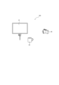
- FIG. 4 is a schematic diagram showing a configuration example of a first environment as a standard environment
- FIG. 4 is a schematic diagram showing a configuration example of a second environment as a user environment
- FIG. 11 is a schematic diagram showing a configuration example for capturing an image of a marker in a second environment
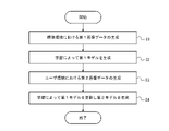
- 4 is a flow chart showing an example procedure of a learned model generation method according to an embodiment
- 9 is a flow chart showing an example of a procedure for generating second image data based on user environment information
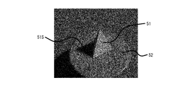
- It is a schematic diagram which shows the structural example by which a marker is illuminated by parallel light. It is an example of an image showing a triangular pyramid marker illuminated with parallel light. It is an example of an image showing a quadrangular pyramid marker illuminated with parallel light. It is an example of an image showing a quadrangular prism marker illuminated with parallel light.
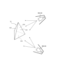
- FIG. 4 is a schematic diagram showing a configuration example in which a marker is illuminated by a spotlight; FIG.
- FIG. 10 is an example image of a triangular pyramid marker illuminated by a spotlight
- FIG. FIG. 4 is a schematic diagram showing a configuration example in which a marker is illuminated from two directions by spotlights; It is an example of an image showing a triangular pyramid marker illuminated from two directions by a spotlight.
- the recognition accuracy may decrease.
- the robustness of the trained model used for recognition may decrease. According to the trained model generation method and user environment estimation method according to an embodiment of the present disclosure, the robustness of the trained model used for recognition can be improved.
- a trained model generation system 1 includes a first trained model generation device 110 and a second trained model generation device 210 .
- the trained model generation system 1 further includes a user environment estimation device 310 although it is not essential.
- the trained model generation system 1 further includes an imaging device 40, although it is not essential.
- the first trained model generating device 110 and the second trained model generating device 210 generate trained models used for estimating an estimation target.
- a trained model is an inference algorithm configured to perform specific arithmetic processing on an input by applying built-in trained parameters and output the arithmetic result. Note that the trained model is used for estimating the estimation target.
- a trained model is used, for example, for recognizing a recognition target or estimating a grasping position of a grasping target.
- This learned model is set, preferred, or downloaded to, for example, a robot controller that controls a robot such as a collaborative robot, and is used when the robot recognizes a work target.
- the learned model captures an image of an object in the work environment, and based on the captured image, the captured object is a work target such as a recognition target or a grasp target. It is possible to determine whether or not the object is an object, and to estimate the gripping position of the gripping target. Then, the robot can be controlled according to the determination result.
- the first trained model generation device 110 generates a first trained model through learning using, as teacher data, an image of the recognition target in the first environment or an image that assumes the appearance of the recognition target in the standard environment.
- the first environment is also referred to as standard environment. That is, in the following description, the term "standard environment” can be replaced with the term "first environment.”
- the first trained model generation device 110 may acquire an image of the recognition target in the standard environment from the imaging device 40 .
- the standard environment may be an environment that reduces the influence exerted on an image obtained by photographing the recognition target or an image that assumes the appearance of the recognition target. In other words, the standard environment may be an environment with less noise than the user environment described below.
- the environmental information is an environment in which factors that may change depending on the environment in which recognition is executed are small.
- the second trained model generation device 210 acquires the first trained model from the first trained model generation device 110 .
- the second trained model generating device 210 updates the first trained model by learning using an image that assumes how the recognition target looks in the second environment where recognition is executed as training data, and generates a second trained model. to generate
- the second environment is also referred to as a user environment. That is, in the following description, the term "user environment” can be replaced with the term "second environment.”
- the environment in which recognition is executed may be, for example, a place where a device such as a robot on which the finally obtained trained model is mounted is used.
- the user environment is an environment different from the standard environment.
- the appearance of the recognition target in the standard environment is the standard appearance.
- the appearance of the recognition target in the user environment differs from the standard appearance. It can be said that the difference from the standard appearance causes noise in the appearance. Therefore, it can be said that the difference between the user environment and the standard environment causes noise in the appearance of the recognition target.
- the trained model generation system 1 can improve the recognition accuracy of the recognition target in each environment by learning based on the difference in appearance of the recognition target in each environment. That is, a model with high robustness against environmental differences can be generated.
- a configuration example of the trained model generation system 1 will be described below.
- the first trained model generation device 110 includes a first control section 120 and a first storage section 130 .
- the first control unit 120 includes a standard environment object data generation unit 121 and a standard environment object recognition unit 122 .
- the first storage unit 130 has a first data holding unit 131 .
- the second trained model generation device 210 includes a second control section 220 and a second storage section 230 .
- the second control unit 220 includes a user environment object data generation unit 223 and a user environment object recognition unit 224 .
- the second storage unit 230 has a second data holding unit 232 .
- the user environment estimation device 310 includes a third control section 320 and a third storage section 330 .
- the third control unit 320 includes a user environment acquisition unit 325 and a user environment estimation unit 326 .
- Third storage unit 330 includes third data holding unit 333 and fourth data holding unit 334 .
- the first trained model generation device 110 and the second trained model generation device 210 may be configured as an integrated device.
- User environment estimation device 310 may be configured as a device integrated with first trained model generation device 110 or second trained model generation device 210 .
- the standard environment object data generation unit 121 generates first image data including an image representing a recognition object in the standard environment.
- the standard environment object data generating unit 121 may acquire an image of the recognition target in the standard environment from the imaging device 40 as the image of the recognition target in the standard environment, and use it as the first image data. Further, the standard environment object data generation unit 121 may generate an image assuming how the recognition target looks in the standard environment as the first image data. That is, the standard environment object data generator 121 may synthesize the first image data based on design data including CAD (Computer-Aided Design) data or drawings, taking into account the state of the standard environment.
- the standard environment object data generation unit 121 outputs the first image data to the standard environment object recognition unit 122 .
- the standard environment object data generation unit 121 may store the first image data in the first data holding unit 131 .
- the standard environment object recognition unit 122 acquires the first image data from the standard environment object data generation unit 121 .
- the standard environment object recognition unit 122 may acquire the first image data from the first data holding unit 131 .
- the standard environment object recognition unit 122 performs recognition learning in the standard environment using the first image data as teacher data, and generates a first trained model.
- the first trained model is also referred to as the first model.
- the standard environment object recognition unit 122 stores the first model generated by learning using the first image data as teacher data in the first data holding unit 131 .
- the user environment object data generation unit 223 generates second image data including an image representing a recognition object in the user environment.
- the user environment target object data generation unit 223 may generate, as the second image data, an image that assumes how the recognition target looks in the user environment.
- the user environment object data generation unit 223 acquires information about the user environment generated by a user environment acquisition unit 325 and a user environment estimation unit 326, which will be described later. Information about the user environment is also referred to as user environment information.
- the user environment object data generation unit 223 generates second image data based on the user environment information. That is, the user environment target object data generation unit 223 may synthesize the second image data based on design data including CAD data or drawings, taking into consideration the state of the user environment.
- the user environment object data generation unit 223 outputs the second image data to the user environment object recognition unit 224 .
- the user environment target object data generation unit 223 may store the second image data in the second data holding unit 232 . Note that the user environment target object data generation unit 223 may acquire an image of a recognition target captured in the user environment and use it as the second image data.
- the user environment object recognition unit 224 acquires the second image data from the user environment object data generation unit 223 . Also, the user environment object recognition unit 224 acquires the first model from the first data holding unit 131 . The user environment object recognition unit 224 performs learning using the second image data as teacher data, and generates a second model based on the first model. In this embodiment, the user environment object recognizer 224 updates the first model to generate the second model. It is assumed that the first model generated by the standard environment object recognition unit 122 and stored in the first data storage unit 131 is stored in the second data storage unit 232 . The user environment object recognition unit 224 updates the first model by reading from and writing to the first model stored in the second data holding unit 232, generates a second trained model, and generates second data.
- the second trained model is also referred to as the second model.
- the user environment object recognition unit 224 outputs the second model as a trained model.
- the user environment object recognizer 224 may output a trained model based on the second model.
- learning may be performed on captured images in the user's environment.
- the first model may be stored in the first data holding unit 131.
- the user environment object recognition unit 224 updates the first model by executing reading and writing with respect to the first model stored in the first data holding unit 131, generates a second model, and updates the first model.
- the first data holding unit 131 and the second data holding unit 232 may be configured so as not to be distinguished from each other, or may be configured integrally.
- a second model may be generated by connecting to the first model an additional trained model that has undergone a learning process related to the user environment, unlike the first model.
- the additional trained model is also called an adapter module, for example.
- the user environment acquisition unit 325 acquires information used to estimate the user environment.
- Information used to estimate the user environment is also referred to as user environment data.
- User environment data may include images taken in the user environment. Specifically, the user environment data is, for example, an image of the recognition target photographed in the user environment, an image of the surroundings of the recognition target photographed in the user environment, or an image photographed of the state in which the recognition target is not arranged in the user environment. etc. should be included.
- User environment data may include known information such as lighting conditions in the user environment.
- User environment acquisition section 325 outputs user environment data to user environment estimation section 326 .
- the user environment acquisition unit 325 may store user environment data in the third data holding unit 333 .
- the user environment estimation unit 326 estimates the user environment based on the user environment data.
- the user environment estimation unit 326 may acquire user environment data from the user environment acquisition unit 325 or from the third data storage unit 333 .
- the user environment may be specified, for example, by lighting conditions.
- the lighting conditions may include, for example, the position or number of lights, the type of light source, the brightness, luminance or illuminance of the lights, the color temperature of the lights, or the flicker of the lights.
- the type of light source may be specified by whether it is parallel light or scattered light.
- the type of light source may be specified as a point light source, a planar light source or a ring light source.
- the user environment may be specified, for example, by the specifications or settings of the imaging device 40 used when recognition is performed.
- the user environment may be specified by the conditions of objects other than the recognition target, such as the table on which the recognition target is placed, or the wall or ceiling of the room where the recognition target is placed.
- the user environment may be specified by the recognition target itself, or by the surface state or reflectance of an object other than the recognition target.
- the user environment may be identified by the presence or absence of windows or the presence or absence of blinds in the room in which the recognition target is placed when recognition is performed.
- the user environment may be identified by a time-series change in the amount of sunlight shining on the location where the recognition object is placed when recognition is performed.
- the user environment estimation unit 326 outputs the estimation result of the user environment to the user environment object data generation unit 223 as user environment information.
- the user environment acquisition unit 325 may store the user environment information in the fourth data holding unit 334 .
- the user environment object data generator 223 may generate the second image data based on the user environment information, as described above.
- the user environment object data generation unit 223 may acquire the user environment information from the user environment estimation unit 326 or from the fourth data storage unit 334 . If the information used for estimating the user environment includes information that can identify the user environment, such as lighting conditions, the user environment estimation unit 326 may output the information itself that can identify the user environment as the user environment information. good.
- the first control unit 120, the second control unit 220, and the third control unit 320 include at least one processor in order to implement the functions of each component such as the standard environment object data generation unit 121. good.
- the processor can execute a program that implements the function of each component.
- a processor may be implemented as a circuit that implements the function of each component.
- a processor may be implemented as a circuit that collectively implements the functions of a plurality of components.
- a processor may be implemented as a single integrated circuit. An integrated circuit is also called an IC (Integrated Circuit).
- a processor may be implemented as a plurality of communicatively coupled integrated and discrete circuits.
- the processor may be configured including a CPU (Central Processing Unit).
- the processor may be configured including a DSP (Digital Signal Processor) or a GPU (Graphics Processing Unit). Processors may be implemented based on various other known technologies.
- the first storage unit 130, the second storage unit 230, and the third storage unit 330 may include an electromagnetic storage medium such as a magnetic disk, or may include a memory such as a semiconductor memory or a magnetic memory. good.
- the first storage unit 130, the second storage unit 230, and the third storage unit 330 may be configured as HDDs (Hard Disk Drives) or SSDs (Solid State Drives).
- the first storage unit 130, the second storage unit 230, and the third storage unit 330 store data separately for each configuration unit, such as the first data storage unit 131. It may be configured including a memory or the like.
- the first storage unit 130, the second storage unit 230, and the third storage unit 330 may be configured to hold data of a plurality of components in one electromagnetic storage medium, memory, or the like.
- the first storage unit 130, the second storage unit 230, and the third storage unit 330 store various information, programs executed by the first control unit 120, the second control unit 220, and the third control unit 320, and the like.
- the first storage unit 130, the second storage unit 230, and the third storage unit 330 may function as work memories for the first control unit 120, the second control unit 220, and the third control unit 320, respectively.
- the first control unit 120 , the second control unit 220 and the third control unit 320 may include at least a part of the first storage unit 130 , the second storage unit 230 and the third storage unit 330 .
- the imaging device 40 is configured to be capable of photographing a recognition target or an object other than a recognition target.
- the imaging device 40 may include an imaging element.
- the imaging device 40 may comprise an optical system including lenses, mirrors, or the like.
- the specifications of the imaging device 40 may be specified by resolution or sensitivity.
- the imaging device 40 may be configured to be able to change the resolution or sensitivity when capturing a recognition target or an object other than the recognition target.
- the specifications of the imaging device 40 may be specified by shutter speed or aperture.
- the imaging device 40 may be configured to be able to change the shutter speed or aperture when capturing an image of a recognition target or an object other than the recognition target.
- the first trained model generation device 110, the second trained model generation device 210, or the user environment estimation device 310 and the imaging device 40 may be configured to communicate with each other by wire or wirelessly.
- the first trained model generation device 110, the second trained model generation device 210, the user environment estimation device 310, and the imaging device 40 may comprise communication devices.
- a communication device may be configured to be able to communicate with communication schemes based on various communication standards.
- a communication device may be configured according to known communication technologies. A detailed description of the hardware of the communication device and the like is omitted.
- the functions of the communication device may be realized by one interface, or may be realized by separate interfaces for each connection destination.
- the first trained model generation device 110 generates a first model by learning based on first image data including an image to be recognized in a standard environment.
- the second trained model generation device 210 updates the first model by learning based on the second image data including the image to be recognized in the user environment, generates the second model, and outputs the second model as a trained model.
- the first control unit 120 of the first trained model generation device 110 generates first image data including an image to be recognized in the standard environment.
- the standard environment is an environment for generating images that serve as teacher data used for learning to generate the first model.
- the first control unit 120 may acquire an image of the image to be recognized in the standard environment and generate first image data including the acquired image.
- the first control unit 120 may generate an image assuming how the recognition target looks in the standard environment, and generate first image data including the generated image.
- the standard environment may be an environment that reduces the influence of at least a shadow caused by the position of the light source on an image of the recognition target or an image that assumes the appearance of the recognition target.
- the standard environment is an environment in which the cup 50 to be recognized is illuminated with the standard lighting 41, as shown in FIG. 3 as the first environment 100, for example.
- the standard illumination 41 may be configured such that it casts no shadows on the object to be recognized.
- the standard illumination 41 may be configured, for example, to emit light that uniformly illuminates the recognition target from all directions.
- the standard lighting 41 may be configured including, for example, a panel-type lighting device.
- Standard lighting 41 may be configured to include multiple lighting devices.
- the standard environment may be a real environment or a virtually set environment.
- the first control unit 120 performs recognition learning in the standard environment using the first image data as teacher data, and generates a first trained model.
- the second control unit 220 of the second trained model generation device 210 generates second image data including an image to be recognized in the user environment based on the user environment information.
- a user environment is an environment in which a recognition target is actually recognized using a trained model.
- the second control unit 220 generates an image based on how the recognition target looks in the user environment, and generates second image data including the generated image.
- the user environment is an environment in which the image of the cup 50 placed on the table 52 is photographed by the imaging device 40 as a recognition target and recognized as shown in FIG. 4 as a second environment 200, for example.
- the shadow 50S of the cup 50 appears on the table 52.
- the second control unit 220 acquires an image of the cup 50, the shadow 50S, and the table 52, that is, an image specifying how the cup 50 appears in the user environment, and generates second image data including the acquired image. good.
- the second control unit 220 acquires user environment information as will be described later, generates an image based on the user environment information assuming how the cup 50 looks in the user environment, and generates second image data including the generated image. may be generated.
- the user lighting 42 may be configured including, for example, a ring-shaped lighting device.
- User lighting 42 may comprise a variety of lighting devices.
- User lighting 42 may be configured to include multiple lighting devices.
- the user environment may be a real environment or a virtual environment.
- the second control unit 220 updates the first model by learning the second image data as teacher data and generates a second model.
- a second model generated by updating the first model can improve recognition accuracy in the user environment.
- the second control unit 220 outputs the second model as a learned model.
- the third control unit 320 of the user environment estimation device 310 may generate the user environment information by estimating it.
- the third control unit 320 can estimate the user environment information based on an image showing the glass 50 and the shadow 50S to be recognized, as shown in FIG. 4, for example.
- the third control unit 320 can estimate the user environment information based on an image showing the marker 51 and the shadow 51S placed in the second environment 200, as shown in FIG. 5, for example.
- the marker 51 may include an object that is a recognition target, or may include an object that is not a recognition target.
- the marker 51 has at least two visible faces.
- the marker 51 is arranged such that the incident angles of the illumination light from the user illumination 42 with respect to the two surfaces are different from each other.
- the marker 51 is arranged so that two surfaces having different incident angles of illumination light are photographed as one image by the imaging device 40 .
- the imaging device 40 may include a first imaging device 40A and a second imaging device 40B.
- the imaging device 40 may be configured to shoot the marker 51 from two directions.
- the markers 51 may be arranged so that different surfaces of the markers 51 appear in the images captured from each direction.
- the third control unit 320 estimates various conditions for specifying the user environment based on the captured image of the marker 51 .
- the third control unit 320 may estimate, for example, lighting conditions or specifications of the imaging device 40 .
- the third control unit 320 may estimate information about an object other than the recognition target, such as the table 52 on which the marker 51 is placed.
- the third control unit 320 generates or acquires conditions specifying the user environment as user environment information.
- the third control unit 320 may generate or acquire, as the user environment information, information specifying factors of noise occurring in the second image data in the user environment.
- the third control unit 320 may generate or acquire, as the user environment information, information specifying factors that cause a difference between the first image data and the second image data.
- the third control unit 320 uses, as user environment information, the position of the light source in the user environment, the intensity of the light emitted from the light source, and the light source type specifying whether the light source is a point light source system or a scattered light system.
- the third control unit 320 may generate or obtain information about As the user environment information, the third control unit 320 receives information on the optical properties of the table (for example, the table 52, etc.) on which the recognition target is placed, or the wall or ceiling of the room on which the recognition target is placed, in the user environment. , may be generated or obtained. As the user environment information, the third control unit 320 may generate or acquire information on shooting parameters of the shooting means used for recognition of the recognition target or information on vibration of the shooting means in the user environment.
- the imaging means may include the imaging device 40 .
- the first control unit 120 of the first trained model generation device 110 and the second control unit 220 of the second trained model generation device 210 perform a trained model generation method including the procedures of the flow charts illustrated in FIGS. may be executed.
- the learned model generation method may be implemented as a learned model generation program that is executed by the processors constituting the first control unit 120 and the second control unit 220 .
- the trained model generation program may be stored on non-transitory computer-readable media.
- the first control unit 120 and the second control unit 220 generate learned models by executing the procedure of the flowchart illustrated in FIG.
- the first control unit 120 generates first image data in the standard environment (step S1).
- the first control unit 120 generates a first model by learning processing using the first image data as learning data and the recognition target object shown in the first learning data as teacher data (step S2).
- the second control unit 220 generates second image data in the user environment (step S3).
- the second control unit 220 updates the first model by learning processing using the second image data as learning data and the recognition target object shown in the second learning data as teaching data, and generates a second model (step S4).
- the second control unit 220 outputs the second model as a learned model.
- the first control unit 120 and the second control unit 220 finish executing the procedure of the flowchart of FIG.
- the third control unit 320 may generate the second image data in the procedure of step S3 in FIG. 6 based on the user environment information.
- the third control unit 320 may generate the user environment information and generate the second image data based on the user environment information by executing the procedure of the flowchart illustrated in FIG.
- the third control unit 320 acquires user environment data (step S11).
- the third control unit 320 generates user environment information based on the user environment data (step S12).
- the third control unit 320 generates second image data based on the user environment information (step S13). After executing the procedure of step S13, the third control unit 320 ends the execution of the procedure of the flowchart of FIG. 7, and proceeds to the procedure of step S4 of FIG.
- the trained model generation system 1, the first trained model generation device 110, and the second trained model generation device 210 generate the first model and the second model separately. and generate a second model by updating the first model based on the user environment information.
- the first trained model generation device 110 and the second trained model generation device 210 update the first model based on the user environment information to generate a second model, thereby generating a trained model as a second model. can improve the robustness of
- the first trained model generation device 110 and the second trained model generation device 210 are common to each user environment in the standard environment in order to generate a second model as a trained model to be applied to a plurality of user environments.
- a first model may be generated.
- the first trained model generation device 110 and the second trained model generation device 210 perform learning based on information on each user environment in order to generate a second model to be applied to each user environment. can update the first model to generate a second model. That is, the first model is a common model for generating second models corresponding to each of a plurality of user environments.
- the versatility of the first model can be enhanced by commonality of the first model.
- the trained model generation system 1 may have a third trained model generation device. Then, a third model relating to the user environment different from the second model may be generated. Note that the third trained model generation device may have the same configuration as the second trained model generation device 210 . A third model may be generated in a similar manner as the second model. Also, a first model common to each user environment may be generated in the standard environment in order to generate a trained model to be applied to each user environment, such as a second model and a third model. After generating the first model, the second trained model generation device 210 and the third trained model generation device generate information about each user environment in order to generate a second model and a third model to be applied to each user environment.
- the first model can be updated by learning based on to generate the second and third models. That is, the first model is a common model for generating the second model and the third model corresponding to each of a plurality of user environments. By sharing the learning for generating the first model, the computational load for learning for generating the second and third models to be applied to each user environment can be reduced. In addition, the versatility of the first model can be enhanced by commonality of the first model.
- the third model may be generated each time, for example. The third model need not be generated at the same time as the second model. Further, even when the second model is generated by updating the first model in order to generate the third model, the first model may be stored as the first model.
- the trained model generation system 1 may have the same number of trained model generation devices as the user environments, and may generate the same number of trained models as the user environments.
- the trained model generation system 1 may have a fourth trained model generation device.
- a fourth model may then be generated based on the second model.
- the control unit of the fourth trained model generation device obtains a photographed image of the user environment, performs additional learning processing on the second model based on the obtained photographed image in the user environment, and generates a fourth model. may be generated.
- the fourth model may be generated by connecting to the second model an additional trained model that has been subjected to learning processing related to images taken in the user environment.
- the versatility and robustness of the trained model can be ensured.
- Lighting conditions in the user's environment affect how objects such as markers 51 appear in the user's environment. The difference in appearance of the marker 51 under different lighting conditions will be described below.
- the marker 51 is illuminated with parallel light from sunlight 43 as a light source.
- the marker 51 is a triangular pyramid and has a first surface 511 , a second surface 512 , a third surface 513 and a fourth surface 514 .
- the imaging device 40 is positioned on the front side of the paper surface and faces the back side of the paper surface to photograph the marker 51 .
- the first surface 511 (see FIG. 8) and the second surface 512 (see FIG. 8) of the marker 51 are shown in the image shown in FIG. 9A.
- the brightness of the first surface 511 located toward the illumination is higher than the brightness of the second surface 512 .
- a shadow 51S of the marker 51 is produced on the table 52 by being illuminated with parallel light.
- the third control unit 320 of the user environment estimation device 310 may estimate lighting conditions for illuminating the marker 51 based on the image shown in FIG. 9A.
- the third control unit 320 may estimate the illumination condition based on the shape of the shadow 51S or the density of the shadow 51S.
- the third control unit 320 may estimate not only the lighting conditions but also the characteristics of the imaging device 40 or information related to objects other than the recognition target such as the table 52 or the floor.
- the third control unit 320 may generate or acquire the estimation result as user environment information.
- FIG. 9B illustrates an image of a quadrangular pyramid marker 51.
- FIG. 9C illustrates an image of the quadrangular prism marker 51 .
- the third control unit 320 may generate or acquire user environment information based on images showing various markers 51 .
- FIG. 10 ⁇ Example of appearance of marker 51 illuminated by spotlight 44>> As shown in FIG. 10, it is assumed that only the periphery of the marker 51 is illuminated with illumination light that spreads radially from a spotlight 44 as a light source. Assume that the marker 51 is a triangular pyramid and has a first surface 511 , a second surface 512 , a third surface 513 and a fourth surface 514 . In FIG. 10, the imaging device 40 is positioned on the front side of the paper and photographs the marker 51 toward the back of the paper.
- the first surface 511 (see FIG. 10) and the second surface 512 (see FIG. 10) of the marker 51 are shown in the image shown in FIG.
- the brightness of the first surface 511 located toward the illumination is higher than the brightness of the second surface 512 .
- a shadow of the marker 51 is produced on the table 52 by illuminating the marker 51 with the illumination light.
- only the vicinity of the marker 51 is bright on the table 52 by illuminating only the periphery of the marker 51 with the radial illumination light.
- double shadows appear due to the diffraction of the illumination light.
- the third control unit 320 may estimate the illumination conditions for illuminating the marker 51 based on the image shown in FIG.
- the third control unit 320 may estimate the illumination condition based on the shape of the shadow of the marker 51 or the density of the shadow of the marker 51 .
- the third control unit 320 may estimate not only the lighting conditions but also the characteristics of the imaging device 40 or information related to objects other than the recognition target such as the table 52 or the floor.
- the third control unit 320 may generate or acquire the estimation result as user environment information.
- FIG. 12 ⁇ Example of Appearance of Marker 51 Illuminated from Two Directions by Spotlight 44>> As shown in FIG. 12, it is assumed that the marker 51 is illuminated from two directions with illumination light from the first spotlight 44A and the second spotlight 44B. Assume that the marker 51 is a triangular pyramid and has a first surface 511 , a second surface 512 , a third surface 513 and a fourth surface 514 . Also, in FIG. 12, the imaging device 40 is positioned on the front side of the paper and faces the back of the paper to capture an image of the marker 51 .
- the first surface 511 (see FIG. 12) and the second surface 512 (see FIG. 12) of the marker 51 are shown in the image shown in FIG.
- the brightness of the first surface 511 located toward the illumination is higher than the brightness of the second surface 512 .
- the shadow of the marker 51 is formed on the table 52 so as to extend in three directions. Specifically, a shadow corresponding to the illumination light from the first spotlight 44A, a shadow corresponding to the second spotlight 44B, and a combined shadow of these two shadows appear on the table 52.
- FIG. 12 The first surface 511 (see FIG. 12) and the second surface 512 (see FIG. 12) of the marker 51 are shown in the image shown in FIG.
- the brightness of the first surface 511 located toward the illumination is higher than the brightness of the second surface 512 .
- the third control unit 320 may estimate lighting conditions for illuminating the marker 51 based on the image shown in FIG.
- the third control unit 320 may estimate the illumination condition based on the shape of the shadow of the marker 51 or the density of the shadow of the marker 51 .
- the third control unit 320 may estimate not only the lighting conditions but also the characteristics of the imaging device 40 or information related to objects other than the recognition target such as the table 52 or the floor.
- the third control unit 320 may generate or acquire the estimation result as user environment information.
- the third control unit 320 can estimate lighting conditions and the like in various user environments based on the image of the marker 51 .
- the third control unit 320 can generate or acquire user environment information based on the estimation result.
- the marker 51 may be arranged so that at least two planes are imaged by the imaging device 40 . Also, the imaging device 40 may be configured to photograph the marker 51 from at least two directions.
- the second control unit 220 of the second trained model generation device 210 or the third control unit 320 of the user environment estimation device 310 generates the second image data based on the user environment information, as described above.
- the second control unit 220 or the third control unit 320 may generate information by changing each parameter of the user environment information within a predetermined range.
- the predetermined range may be set, for example, to a range in which the environmental information changes in the user environment during the time when the second model is used for recognition.
- Information obtained by changing at least one of a plurality of parameters of the user environment information is also called extended environment information.
- the second control unit 220 or the third control unit 320 may generate a plurality of pieces of extended environment information, and generate second image data including an image that assumes how the recognition target looks in each piece of extended environment information.
- the robustness of the trained model can be improved by learning images assuming how the recognition target looks in the extended environment information as training data.
- the user environment estimation device 310 acquires image data obtained by photographing a predetermined object in the user environment.
- the predetermined object may include the recognition target itself, or may include an object such as the marker 51 that is different from the recognition target.
- the user environment estimation device 310 may acquire image data by imaging means, or may acquire image data from the outside.
- a user environment estimation device 310 estimates a user environment based on image data.
- the user environment estimation device 310 may estimate the user environment based on image data obtained by photographing a predetermined object from each of a plurality of directions. Also, the user environment estimation device 310 may estimate the user environment based on images obtained by photographing at least two surfaces of a plurality of surfaces of a predetermined object. Also, the user environment estimation device 310 may estimate the user environment based on images obtained by photographing two different surfaces of the predetermined object from at least two directions.
- the ability of the user environment estimation device 310 to generate user environment information facilitates the collection of user environment information.
- the function of the user environment estimation device 310 may be implemented as a user environment estimation method executed by the user environment estimation device 310.
- the functions of the user environment estimation device 310 may be implemented as a user environment estimation program executed by a processor included in the user environment estimation device 310 .
- a user environment estimation program can estimate the user environment by comparing user environment data with reference data indicating a predefined basic environment. Note that the user environment estimation program and the reference data may be stored in the third data holding unit 333 or the fourth data holding unit 334.
- the trained model generation system 1 generates a trained model that considers noise that occurs in the appearance in the user environment with respect to the standard appearance of the recognition target.
- a configuration for acquiring image data will be described below as an example of factors that cause noise.
- image data acquisition configuration that acquires an optical image of an object as digital data
- the light source of illumination hits the object, and the reflected light is converted into a photoelectric signal by an optical sensor (image pickup element, etc.) of a camera (image pickup device 40, etc.).
- Image data is obtained by converting the electrical signals into digital data. Therefore, image data is affected by various optical or electrical variations and noise.
- Image data noise includes noise caused by the camera.
- Camera-induced noise includes, for example, color variations and noise due to the ISO sensitivity of the photosensor, or luminance variations and noise.
- a camera secures a dynamic range by changing the ISO sensitivity (amplification factor) of a photosensor based on the state of light input at the time of photographing. Increasing the sensitivity of the optical sensor can increase noise.
- the camera shutter speed and aperture are parameters that change the light input state, and are parameters related to ISO sensitivity. These parameters can be easily referred to by being embedded in the image data as Exif (Exchangeable Image File Format) data.
- camera-induced noise includes color reproducibility variation and noise due to the color reproduction range restrictions of the optical sensor.
- Camera-induced noise includes distortion variation and noise in an optical system such as an optical lens, or vignetting variation and noise. Further, the noise caused by the camera includes noise based on the manner in which the camera is held, such as shake (vibration) noise between the camera holding member and the camera due to the influence of ambient vibration.
- Image data noise includes noise caused by lighting.
- Illumination-induced noise includes, for example, object shadow noise associated with the illumination position (illumination coordinates).
- Noise caused by illumination includes object contrast variation and noise due to the type of light source (parallel light, scattered light, etc.), or object shadow noise.
- Noise caused by illumination includes object contrast variation and noise due to illuminance (brightness), or object shadow noise.
- the noise caused by illumination includes color shift variation and noise due to the color temperature of illumination.
- the noise caused by illumination includes variations in light and dark flicker and noise associated with the type of illumination, brightness adjustment, and the like.
- the noise of the image data includes noise caused by the workbench such as the table 52.
- the noise caused by the workbench includes variations in reflectance due to the surface state of the workbench or noise due to reflected light from the surface of the workbench.
- the noise caused by the workbench includes noise that is poorly separated from the object due to the color of the workbench.
- the noise in the image data includes noise caused by the object.
- the noise caused by the object includes variations in reflectance due to the surface state of the object, or noise caused by reflected light.
- the second control unit 220 of the second trained model generation device 210 or the third control unit 320 of the user environment estimation device 310 estimates each factor of noise in the image data described above based on the user environment data, User environment information may be generated.
- the second control unit 220 or the third control unit 320 may estimate some or all of the multiple factors of noise in the image data. That is, the second control unit 220 or the third control unit 320 may estimate at least some of the multiple factors of noise in the image data.
- the noise caused by each of the factors described above greatly affects the recognition of the object.
- the trained model generation system 1 according to the present embodiment can generate a trained model by learning using teacher data that considers these noises. As a result, the robustness of the trained model can be improved.
- the trained model generation system 1 can generate a trained model suitable for each user environment based on user environment information.
- User environment information can be generated based on an image of the marker 51 captured in the user environment.
- An example of the structure of the marker 51 is described below.
- the user's image acquisition environment is affected by various optical or electrical variations and noise. Therefore, it is necessary to acquire the user environment in order to improve robustness.
- a marker 51 having the following three-dimensional structure can be used to acquire the user environment.
- the marker 51 may be of polyhedral structure and have at least three sides.
- the marker 51 may have a structure that can determine the shade of a shadow produced on each surface when illuminated by illumination.
- the marker 51 may have a ridgeline that clearly defines the boundaries of each surface.
- the marker 51 may have a structure that can determine the reflectance of light on each surface.
- the marker 51 may have, for example, a mark representing a specified size or a scale of dimensions as a structure for recognizing its size.
- the marker 51 may have a grid-like pattern or the like so that characteristics such as distortion of the optical system of the photographing means can be determined.
- the marker 51 may have a portion of known density, for example 18% of grayscale.
- the marker 51 may have a portion that is a white point.
- the marker 51 may be arranged so that at least two surfaces are photographed by the photographing means. Also, the marker 51 may be arranged so as to be photographed from at least two or more different angular directions.
- the second control unit 220 of the second trained model generation device 210 or the third control unit 320 of the user environment estimation device 310 determines, based on the image data of the marker 51, the lighting conditions in the user environment such as the lighting position, The brightness, luminance or illuminance of lighting or the type of light source may be estimated. Also, the second control unit 220 or the third control unit 320 may estimate the reflectance of the marker 51 or an object such as a workbench existing around it. The second controller 220 or the third controller 320 may estimate the illumination position based on the size and shadow of the marker 51 . The second control unit 220 or the third control unit 320 may estimate the brightness of the illumination based on the density of the image showing the marker 51 and the ISO sensitivity, shutter speed or aperture of the camera.
- the second control unit 220 or the third control unit 320 estimates the contrast based on the image data of the edge portion of the marker 51 and the image data of the edge portion of the shadow, and determines the type of lighting source (parallel light, scattered light, etc.). ) may be estimated.
- the second control unit 220 or the third control unit 320 may estimate the illumination condition based on the pixel density distribution of the edge portion of the marker 51 and the edge portion of the shadow.
- the second controller 220 or the third controller 320 may estimate the reflectance of the marker 51 based on the reflected image of the marker 51 .
- the second control unit 220 or the third control unit 320 may estimate information about surrounding objects reflected in the marker 51 based on the reflected image of the marker 51 .
- the second controller 220 or the third controller 320 may estimate the color temperature or spectrum of the illumination based on the white point image of the marker 51 .
- the second control unit 220 or the third control unit 320 may estimate the distortion of the optical system of the photographing means based on the grid pattern image of the marker 51 .
- the trained model generation system 1 includes, in object recognition for recognizing objects, a first recognition for recognizing an object in a standard environment and a second recognition for recognizing an object in a user environment.
- the trained model generation system 1 may store at least the object recognition algorithm, or the object recognition algorithm and the object data set.
- the standard environment object data generation means for the first recognition includes illumination, an illumination holding member for holding the illumination, an object and a member for holding the object, and an object. It may be configured with an image conversion system that digitizes. Also, the illumination of the standard environment object data generating means for the first recognition may be composed of two or more illuminations. Also, the illumination of the first recognition standard environment object data generating means may be configured such that the color temperature of the illumination can be adjusted. Further, the image conversion system for converting the object of the standard environment object data generating means for the first recognition into data generates data based on a two-dimensional color image or a three-dimensional color image and distance data.
- the standard environment object data generating means for the first recognition may be configured in a virtual environment.
- the target object recognition algorithm which is sufficiently learned in the first recognition and is retained, or the target object recognition algorithm and the target object data set, is transferred to the second recognition.
- the second recognition user environment object data generating means may be configured to configure a user environment based on the result of estimating the user environment and perform recognition.
- the user environment based on the result of estimating the user environment by the second recognized user environment target object data generation means includes illumination, a lighting holding member for holding the illumination, an object and a member for holding the object, and an object It may be configured with an image conversion system that digitizes an object.
- the illumination of the user environment object data generating means of the second recognition may be composed of two or more illuminations.
- the lighting of the user environment object data generating means of the second perception may be configured such that the color temperature of the lighting can be adjusted.
- the image conversion system for converting the object of the second recognition user environment object data generating means into data generates data based on a two-dimensional color image or a three-dimensional color image and distance data. may be configured to Also, in the second recognition, the object may be recognized by constructing a virtual user environment based on the result of estimating the user environment.
- the standard environment and the user environment may have common environmental elements. That is, for example, when generating the first image data taking into account the standard environment, when generating the second image data taking into account the user environment, when generating the second image data taking into account the user environment, You may generate
- the user environment may have means for measuring the user environment and means for estimating the user environment from information obtained therefrom.
- the means for measuring the user environment has a three-dimensional object, and acquires physical information (size, density, reflection) of the three-dimensional object and user environment data such as image data of the three-dimensional object from two or more different angles. It may be configured as Further, the user environment information such as the lighting position, the number of lights, the brightness, the light source type, or the reflectance may be estimated by the environment estimation means from the user environment data. Also, the means for estimating the user environment from the user environment data may be configured to geometrically estimate the user environment from the two image data. Also, the three-dimensional object for measuring the user environment may have a white object as the three-dimensional object.
- a white object may be placed near the three-dimensional object.
- the three-dimensional object for measuring the user environment may have a grayscale density object on the three-dimensional object.
- a grayscale density object may be placed near the three-dimensional object.
- the reflectance of the grayscale tint may be 18%.
- the image data of the three-dimensional object may include a two-dimensional color image, or a three-dimensional color image and distance data.
- the trained model generation system 1 may be configured to store or accumulate user environment data. Also, the trained model generation system 1 may be configured to store or accumulate user environment information.
- the user environment object recognition unit 224 and the standard environment object recognition unit 122 may be configured identically or similarly. Even if the user environment object recognition unit 224 and the standard environment object recognition unit 122 are the same, the learning result may differ depending on the input standard environment or user environment data.
- the first trained model generation device 110 and the second trained model generation device 210 may be configured as the same device.
- the temporal timings to be generated may be different timings.
- the standard environment object data generation unit 121 and the user environment object data generation unit 223 may be configured as a common object data generation unit.
- An object data generation unit functioning as the standard environment object data generation unit 121 generates standard environment object data by reading standard environment information.
- the object data generator functioning as the user environment object data generator 223 generates user environment object data by reading the user environment information.
- the function of the user environment estimation unit 326 of the third control unit 320 of the user environment estimation device 310 may be realized by the second control unit 220 of the second trained model generation device 210.
- the function of the fourth data holding unit 334 of the third storage unit 330 of the user environment estimation device 310 is implemented by the second storage unit 230 of the second trained model generation device 210 .
- the second trained model generation device 210 is owned by a vendor that provides trained models.
- the user environment estimation device 310 is owned by a user who performs recognition using a trained model.
- the function of the user environment estimation unit 326 is implemented by the second trained model generation device 210, so that the vendor estimates the user environment. In other words, there is no need for the user to estimate the user environment. User convenience is improved.
- Embodiments according to the present disclosure are not limited to any specific configuration of the embodiments described above. Embodiments of the present disclosure extend to any novel feature or combination thereof described in the present disclosure or any novel method or process step or combination thereof described. be able to.
- a part of the method according to the present disclosure may be manually performed by a human.
- a start instruction for learning model generation may be manually executed.
- the folder in which the training data set is saved can be manually specified.
- the trained model generation system 1 according to the present disclosure, the trained model generation device such as the first trained model generation device 110 or the second trained model generation device 210, or the user environment estimation device 310 is manually executed by a human. It may be configured to accept input as to what it intends to do.
- the trained model generation system 1 may be communicably connected to the trained model generation device, the user environment estimation device 310, or the like, and may have an input device that accepts user input.
- the trained model generation device, the user environment estimation device 310, or the like may have an input unit that receives user input.
- the trained model generation system 1 and the like can, for example, accept input of a user's instruction to start work, or accept user input specifying a storage destination for learning data during learning processing.
- the input device or input unit may include, for example, a touch panel or touch sensor, or a pointing device such as a mouse.
- the input device or input unit may include a physical key, or may include a voice input device such as a microphone.
- the present disclosure can also be implemented as a trained model generation device.
- the trained model generation device in one embodiment (1) having a control unit;
- the control unit Acquiring a first model that has been subjected to learning processing for the estimation target using first image data indicating the estimation target in the first environment as learning data; obtaining second image data representing the estimation target in a second environment in which estimation is performed; generating a second model based on the first model using the second image data as learning data; outputting a trained model based on the second model;
- the second image data includes an image assuming how the estimation target looks in the second environment based on user environment information regarding the second environment.
- the first environment is based on at least the position of a light source with respect to an image of the estimation target or an image that assumes how the estimation target looks. It may be an environment that reduces the influence of shadows caused by
- control unit stores, as the user environment information, information specifying factors of noise occurring in the second image data in the second environment. may be obtained.
- the control unit in the trained model generation device, the control unit generates a difference between the first image data and the second image data as the user environment information. Information identifying factors may be obtained.
- the control unit uses, as the user environment information, the position of a light source in the second environment, the light emitted from the light source, Light intensity and light source type information specifying whether the light source is a point light system or a scattered light system may be obtained.
- control unit may set, as the user environment information, a table on which the estimation target is arranged in the second environment. Optical property information may be obtained.
- the control unit recognizes the estimation target in the second environment as the user environment information. Information on the imaging parameters of the imaging means used for the above may be obtained.
- control unit includes, as the user environment information, photographing means used for recognizing the estimation target in the second environment. may obtain information about the vibration of the
- control unit In any one of the trained model generating devices from (1) to (8) above, the control unit generates a plurality of extended environment information in which each parameter of the user environment information is changed within a predetermined range. and generating the second image data in each of the extended environment information.
- the present disclosure can also be implemented as a user environment estimation device.
- the user environment estimation device in one embodiment (10)
- a control unit for estimating a user environment which is an environment for acquiring data to be estimated,
- the control unit outputs a result of estimating the user environment based on image data obtained by photographing a predetermined object in the user environment as user environment information related to the user environment.
- control unit estimates the user environment based on image data obtained by photographing an object different from the estimation target as the predetermined object in the user environment. good.
- the control unit estimates the user environment based on image data obtained by photographing the estimation target as the predetermined object in the user environment. good.
- the control unit estimates the user environment based on image data obtained by photographing the predetermined object from each of a plurality of directions. You can
- the image data is an image obtained by photographing at least two of the plurality of surfaces of the predetermined object, or It may include images obtained by photographing two different surfaces of a given object from at least two directions.
- the present disclosure can also be implemented as a trained model generation program.
- the trained model generation program in one embodiment (15) Acquiring a first model that has undergone a learning process related to the estimation target using first image data representing the estimation target in the first environment as learning data; obtaining second image data representing the estimation target in a second environment in which estimation is performed; generating a second model based on the first model using the second image data as learning data; causing a trained model generation device to output a trained model based on the second model;
- the second image data includes an image assuming how the estimation target looks in the second environment based on user environment information regarding the second environment.
- the present disclosure can also be implemented as a user environment estimation program.
- the user environment estimation program in one embodiment (16) Outputting a result of estimating the user environment based on image data obtained by photographing a predetermined object in the user environment as user environment information related to the user environment.
- the present disclosure can also be implemented as a trained model generation system.
- the trained model generation system in one embodiment (17)
- the learned model generation device acquires user environment information estimated by the user environment estimation device from the user environment estimation device.
- first imaging device 40A: first imaging device, 40B: second imaging device
- standard illumination 42 user illumination
- sunlight 44 spotlight 44A: first spotlight, 44B: second spotlight
- Cup 50S: Shadow of the Cup
- Markers 51S: Marker Shadows, 511-514: First to Fourth Surfaces
- Second trained model generation device (220: second control unit, 223: user environment object data generation unit, 224: user environment object recognition unit, 230: second storage unit, 232: second data holding unit)
- user environment estimation device 320: third control unit, 325: user environment acquisition unit, 326: user environment estimation unit, 330: third storage unit, 333: third data storage unit, 334: fourth data storage unit
Landscapes
- Engineering & Computer Science (AREA)
- Theoretical Computer Science (AREA)
- Databases & Information Systems (AREA)
- Evolutionary Computation (AREA)
- General Physics & Mathematics (AREA)
- Multimedia (AREA)
- Physics & Mathematics (AREA)
- Health & Medical Sciences (AREA)
- Computer Vision & Pattern Recognition (AREA)
- Computing Systems (AREA)
- Artificial Intelligence (AREA)
- General Health & Medical Sciences (AREA)
- Medical Informatics (AREA)
- Software Systems (AREA)
- Image Analysis (AREA)
Priority Applications (5)
| Application Number | Priority Date | Filing Date | Title |
|---|---|---|---|
| EP22849507.3A EP4379670A4 (en) | 2021-07-26 | 2022-07-26 | TRAINED MODEL GENERATION METHOD, USER ENVIRONMENT ESTIMATION METHOD, LEARNED MODEL GENERATION DEVICE, USER ENVIRONMENT ESTIMATION DEVICE, AND LEARNED MODEL GENERATION SYSTEM |
| JP2023538568A JP7537027B2 (ja) | 2021-07-26 | 2022-07-26 | 学習済みモデル生成方法、学習済みモデル生成装置、及び学習済みモデル生成システム |
| CN202280052627.4A CN117716396A (zh) | 2021-07-26 | 2022-07-26 | 训练模型生成方法、用户环境估计方法、训练模型生成设备、用户环境估计设备和训练模型生成系统 |
| US18/292,854 US20240273881A1 (en) | 2021-07-26 | 2022-07-26 | Trained model generating method, user environment estimating method, trained model generating device, user environment estimating device, and trained model generating system |
| JP2024131157A JP2024152811A (ja) | 2021-07-26 | 2024-08-07 | 学習済みモデル生成方法、ユーザ環境推定方法、学習済みモデル生成装置、ユーザ環境推定装置、及び学習済みモデル生成システム |
Applications Claiming Priority (2)
| Application Number | Priority Date | Filing Date | Title |
|---|---|---|---|
| JP2021121958 | 2021-07-26 | ||
| JP2021-121958 | 2021-07-26 |
Publications (1)
| Publication Number | Publication Date |
|---|---|
| WO2023008446A1 true WO2023008446A1 (ja) | 2023-02-02 |
Family
ID=85087653
Family Applications (1)
| Application Number | Title | Priority Date | Filing Date |
|---|---|---|---|
| PCT/JP2022/028834 Ceased WO2023008446A1 (ja) | 2021-07-26 | 2022-07-26 | 学習済みモデル生成方法、ユーザ環境推定方法、学習済みモデル生成装置、ユーザ環境推定装置、及び学習済みモデル生成システム |
Country Status (5)
| Country | Link |
|---|---|
| US (1) | US20240273881A1 (https=) |
| EP (1) | EP4379670A4 (https=) |
| JP (2) | JP7537027B2 (https=) |
| CN (1) | CN117716396A (https=) |
| WO (1) | WO2023008446A1 (https=) |
Citations (5)
| Publication number | Priority date | Publication date | Assignee | Title |
|---|---|---|---|---|
| WO2013175792A1 (ja) * | 2012-05-23 | 2013-11-28 | パナソニック株式会社 | 人物属性推定システム、及び学習用データ生成装置 |
| JP2014199584A (ja) * | 2013-03-29 | 2014-10-23 | キヤノン株式会社 | 画像処理装置および画像処理方法 |
| JP2016006627A (ja) * | 2014-05-28 | 2016-01-14 | ソニー株式会社 | 画像処理装置と画像処理方法 |
| WO2019155593A1 (ja) | 2018-02-09 | 2019-08-15 | 株式会社Fuji | 部品画像認識用学習済みモデル作成システム及び部品画像認識用学習済みモデル作成方法 |
| WO2021014878A1 (ja) * | 2019-07-25 | 2021-01-28 | オムロン株式会社 | 推論装置、推論方法、及び推論プログラム |
Family Cites Families (4)
| Publication number | Priority date | Publication date | Assignee | Title |
|---|---|---|---|---|
| US20180211121A1 (en) * | 2017-01-25 | 2018-07-26 | Ford Global Technologies, Llc | Detecting Vehicles In Low Light Conditions |
| JP2019032694A (ja) | 2017-08-08 | 2019-02-28 | キヤノン株式会社 | 情報処理装置、システム、情報処理方法及びプログラム |
| CN112912896B (zh) | 2018-12-14 | 2024-06-28 | 苹果公司 | 机器学习辅助的图像预测 |
| JP7375405B2 (ja) | 2019-09-19 | 2023-11-08 | 株式会社大林組 | 学習支援システム、学習支援方法及び学習支援プログラム |
-
2022
- 2022-07-26 WO PCT/JP2022/028834 patent/WO2023008446A1/ja not_active Ceased
- 2022-07-26 JP JP2023538568A patent/JP7537027B2/ja active Active
- 2022-07-26 CN CN202280052627.4A patent/CN117716396A/zh active Pending
- 2022-07-26 EP EP22849507.3A patent/EP4379670A4/en active Pending
- 2022-07-26 US US18/292,854 patent/US20240273881A1/en active Pending
-
2024
- 2024-08-07 JP JP2024131157A patent/JP2024152811A/ja active Pending
Patent Citations (5)
| Publication number | Priority date | Publication date | Assignee | Title |
|---|---|---|---|---|
| WO2013175792A1 (ja) * | 2012-05-23 | 2013-11-28 | パナソニック株式会社 | 人物属性推定システム、及び学習用データ生成装置 |
| JP2014199584A (ja) * | 2013-03-29 | 2014-10-23 | キヤノン株式会社 | 画像処理装置および画像処理方法 |
| JP2016006627A (ja) * | 2014-05-28 | 2016-01-14 | ソニー株式会社 | 画像処理装置と画像処理方法 |
| WO2019155593A1 (ja) | 2018-02-09 | 2019-08-15 | 株式会社Fuji | 部品画像認識用学習済みモデル作成システム及び部品画像認識用学習済みモデル作成方法 |
| WO2021014878A1 (ja) * | 2019-07-25 | 2021-01-28 | オムロン株式会社 | 推論装置、推論方法、及び推論プログラム |
Non-Patent Citations (1)
| Title |
|---|
| See also references of EP4379670A4 |
Also Published As
| Publication number | Publication date |
|---|---|
| CN117716396A (zh) | 2024-03-15 |
| JP7537027B2 (ja) | 2024-08-20 |
| JPWO2023008446A1 (https=) | 2023-02-02 |
| US20240273881A1 (en) | 2024-08-15 |
| EP4379670A4 (en) | 2025-05-14 |
| JP2024152811A (ja) | 2024-10-25 |
| EP4379670A1 (en) | 2024-06-05 |
Similar Documents
| Publication | Publication Date | Title |
|---|---|---|
| US11869139B2 (en) | System and method for three-dimensional scanning and for capturing a bidirectional reflectance distribution function | |
| CN106548455B (zh) | 用于调整图像的亮度的设备和方法 | |
| US20070176927A1 (en) | Image Processing method and image processor | |
| CN109831660A (zh) | 深度图像获取方法、深度图像获取模组及电子设备 | |
| CN101946117A (zh) | 光投影装置、照明装置 | |
| JPWO2015098288A1 (ja) | 画像処理装置、および画像処理方法 | |
| CN111627008A (zh) | 一种基于图像融合的物体表面检测方法及系统、存储介质 | |
| CN103780835A (zh) | 标识设备和方法 | |
| JP2022523122A (ja) | 可動スキャナを使用したテクスチャモデルの生成 | |
| US9204130B2 (en) | Method and system for creating a three dimensional representation of an object | |
| JP2003208601A (ja) | 3次元物体撮影装置、3次元形状モデル生成装置、3次元形状モデル生成方法、3次元形状モデル生成プログラム | |
| JP2018163648A (ja) | 画像処理装置、画像処理方法、及びプログラム | |
| EP3381015B1 (en) | Systems and methods for forming three-dimensional models of objects | |
| CN114004935A (zh) | 通过三维建模系统进行三维建模的方法和装置 | |
| JP7537027B2 (ja) | 学習済みモデル生成方法、学習済みモデル生成装置、及び学習済みモデル生成システム | |
| JP6835020B2 (ja) | 画像処理システム、画像処理装置、画像処理プログラム | |
| JP5441752B2 (ja) | 環境内の3d物体の3d姿勢を推定する方法及び装置 | |
| CN108876891B (zh) | 人脸图像数据采集方法及人脸图像数据采集装置 | |
| JP5510175B2 (ja) | 光源方向特定装置及び光源方向特定プログラム | |
| JP5506371B2 (ja) | 画像処理装置、画像処理方法およびプログラム | |
| KR100879328B1 (ko) | 카메라를 이용한 핑거 뎁스 조절 장치 및 방법과 카메라를 이용한 핑거 뎁스 조절 장치를 갖는 터치 스크린 | |
| US20180130230A1 (en) | Recognition apparatus, determination method, and article manufacturing method | |
| CN103299156B (zh) | 创建三维图像文件的系统和方法 | |
| CN109472235B (zh) | 姿态确定方法、装置和计算机可读存储介质 | |
| JP2019082955A (ja) | 画像処理装置、画像処理方法及びプログラム |
Legal Events
| Date | Code | Title | Description |
|---|---|---|---|
| 121 | Ep: the epo has been informed by wipo that ep was designated in this application |
Ref document number: 22849507 Country of ref document: EP Kind code of ref document: A1 |
|
| WWE | Wipo information: entry into national phase |
Ref document number: 2023538568 Country of ref document: JP |
|
| WWE | Wipo information: entry into national phase |
Ref document number: 18292854 Country of ref document: US Ref document number: 202280052627.4 Country of ref document: CN |
|
| WWE | Wipo information: entry into national phase |
Ref document number: 2022849507 Country of ref document: EP |
|
| NENP | Non-entry into the national phase |
Ref country code: DE |
|
| ENP | Entry into the national phase |
Ref document number: 2022849507 Country of ref document: EP Effective date: 20240226 |