WO2023007863A1 - 光学系及びそれを備えたヘッドアップディスプレイシステム - Google Patents
光学系及びそれを備えたヘッドアップディスプレイシステム Download PDFInfo
- Publication number
- WO2023007863A1 WO2023007863A1 PCT/JP2022/016242 JP2022016242W WO2023007863A1 WO 2023007863 A1 WO2023007863 A1 WO 2023007863A1 JP 2022016242 W JP2022016242 W JP 2022016242W WO 2023007863 A1 WO2023007863 A1 WO 2023007863A1
- Authority
- WO
- WIPO (PCT)
- Prior art keywords
- light
- axis
- incident
- light beam
- image
- Prior art date
- Legal status (The legal status is an assumption and is not a legal conclusion. Google has not performed a legal analysis and makes no representation as to the accuracy of the status listed.)
- Ceased
Links
Images












Classifications
-
- G—PHYSICS
- G02—OPTICS
- G02B—OPTICAL ELEMENTS, SYSTEMS OR APPARATUS
- G02B27/00—Optical systems or apparatus not provided for by any of the groups G02B1/00 - G02B26/00, G02B30/00
- G02B27/01—Head-up displays
-
- B—PERFORMING OPERATIONS; TRANSPORTING
- B60—VEHICLES IN GENERAL
- B60K—ARRANGEMENT OR MOUNTING OF PROPULSION UNITS OR OF TRANSMISSIONS IN VEHICLES; ARRANGEMENT OR MOUNTING OF PLURAL DIVERSE PRIME-MOVERS IN VEHICLES; AUXILIARY DRIVES FOR VEHICLES; INSTRUMENTATION OR DASHBOARDS FOR VEHICLES; ARRANGEMENTS IN CONNECTION WITH COOLING, AIR INTAKE, GAS EXHAUST OR FUEL SUPPLY OF PROPULSION UNITS IN VEHICLES
- B60K35/00—Instruments specially adapted for vehicles; Arrangement of instruments in or on vehicles
- B60K35/20—Output arrangements, i.e. from vehicle to user, associated with vehicle functions or specially adapted therefor
- B60K35/21—Output arrangements, i.e. from vehicle to user, associated with vehicle functions or specially adapted therefor using visual output, e.g. blinking lights or matrix displays
- B60K35/211—Output arrangements, i.e. from vehicle to user, associated with vehicle functions or specially adapted therefor using visual output, e.g. blinking lights or matrix displays producing three-dimensional [3D] effects, e.g. stereoscopic images
-
- B—PERFORMING OPERATIONS; TRANSPORTING
- B60—VEHICLES IN GENERAL
- B60K—ARRANGEMENT OR MOUNTING OF PROPULSION UNITS OR OF TRANSMISSIONS IN VEHICLES; ARRANGEMENT OR MOUNTING OF PLURAL DIVERSE PRIME-MOVERS IN VEHICLES; AUXILIARY DRIVES FOR VEHICLES; INSTRUMENTATION OR DASHBOARDS FOR VEHICLES; ARRANGEMENTS IN CONNECTION WITH COOLING, AIR INTAKE, GAS EXHAUST OR FUEL SUPPLY OF PROPULSION UNITS IN VEHICLES
- B60K35/00—Instruments specially adapted for vehicles; Arrangement of instruments in or on vehicles
- B60K35/20—Output arrangements, i.e. from vehicle to user, associated with vehicle functions or specially adapted therefor
- B60K35/21—Output arrangements, i.e. from vehicle to user, associated with vehicle functions or specially adapted therefor using visual output, e.g. blinking lights or matrix displays
- B60K35/23—Head-up displays [HUD]
-
- B—PERFORMING OPERATIONS; TRANSPORTING
- B60—VEHICLES IN GENERAL
- B60K—ARRANGEMENT OR MOUNTING OF PROPULSION UNITS OR OF TRANSMISSIONS IN VEHICLES; ARRANGEMENT OR MOUNTING OF PLURAL DIVERSE PRIME-MOVERS IN VEHICLES; AUXILIARY DRIVES FOR VEHICLES; INSTRUMENTATION OR DASHBOARDS FOR VEHICLES; ARRANGEMENTS IN CONNECTION WITH COOLING, AIR INTAKE, GAS EXHAUST OR FUEL SUPPLY OF PROPULSION UNITS IN VEHICLES
- B60K35/00—Instruments specially adapted for vehicles; Arrangement of instruments in or on vehicles
- B60K35/20—Output arrangements, i.e. from vehicle to user, associated with vehicle functions or specially adapted therefor
- B60K35/21—Output arrangements, i.e. from vehicle to user, associated with vehicle functions or specially adapted therefor using visual output, e.g. blinking lights or matrix displays
- B60K35/23—Head-up displays [HUD]
- B60K35/233—Head-up displays [HUD] controlling the size or position in display areas of virtual images depending on the condition of the vehicle or the driver
-
- B—PERFORMING OPERATIONS; TRANSPORTING
- B60—VEHICLES IN GENERAL
- B60K—ARRANGEMENT OR MOUNTING OF PROPULSION UNITS OR OF TRANSMISSIONS IN VEHICLES; ARRANGEMENT OR MOUNTING OF PLURAL DIVERSE PRIME-MOVERS IN VEHICLES; AUXILIARY DRIVES FOR VEHICLES; INSTRUMENTATION OR DASHBOARDS FOR VEHICLES; ARRANGEMENTS IN CONNECTION WITH COOLING, AIR INTAKE, GAS EXHAUST OR FUEL SUPPLY OF PROPULSION UNITS IN VEHICLES
- B60K35/00—Instruments specially adapted for vehicles; Arrangement of instruments in or on vehicles
- B60K35/60—Instruments characterised by their location or relative disposition in or on vehicles
-
- B—PERFORMING OPERATIONS; TRANSPORTING
- B60—VEHICLES IN GENERAL
- B60K—ARRANGEMENT OR MOUNTING OF PROPULSION UNITS OR OF TRANSMISSIONS IN VEHICLES; ARRANGEMENT OR MOUNTING OF PLURAL DIVERSE PRIME-MOVERS IN VEHICLES; AUXILIARY DRIVES FOR VEHICLES; INSTRUMENTATION OR DASHBOARDS FOR VEHICLES; ARRANGEMENTS IN CONNECTION WITH COOLING, AIR INTAKE, GAS EXHAUST OR FUEL SUPPLY OF PROPULSION UNITS IN VEHICLES
- B60K35/00—Instruments specially adapted for vehicles; Arrangement of instruments in or on vehicles
- B60K35/80—Arrangements for controlling instruments
- B60K35/81—Arrangements for controlling instruments for controlling displays
-
- G—PHYSICS
- G02—OPTICS
- G02B—OPTICAL ELEMENTS, SYSTEMS OR APPARATUS
- G02B27/00—Optical systems or apparatus not provided for by any of the groups G02B1/00 - G02B26/00, G02B30/00
- G02B27/0081—Optical systems or apparatus not provided for by any of the groups G02B1/00 - G02B26/00, G02B30/00 with means for altering, e.g. enlarging, the entrance or exit pupil
-
- G—PHYSICS
- G02—OPTICS
- G02B—OPTICAL ELEMENTS, SYSTEMS OR APPARATUS
- G02B27/00—Optical systems or apparatus not provided for by any of the groups G02B1/00 - G02B26/00, G02B30/00
- G02B27/01—Head-up displays
- G02B27/0101—Head-up displays characterised by optical features
-
- G—PHYSICS
- G02—OPTICS
- G02B—OPTICAL ELEMENTS, SYSTEMS OR APPARATUS
- G02B27/00—Optical systems or apparatus not provided for by any of the groups G02B1/00 - G02B26/00, G02B30/00
- G02B27/01—Head-up displays
- G02B27/0101—Head-up displays characterised by optical features
- G02B27/0103—Head-up displays characterised by optical features comprising holographic elements
-
- G—PHYSICS
- G02—OPTICS
- G02B—OPTICAL ELEMENTS, SYSTEMS OR APPARATUS
- G02B27/00—Optical systems or apparatus not provided for by any of the groups G02B1/00 - G02B26/00, G02B30/00
- G02B27/01—Head-up displays
- G02B27/017—Head mounted
- G02B27/0172—Head mounted characterised by optical features
-
- G—PHYSICS
- G02—OPTICS
- G02B—OPTICAL ELEMENTS, SYSTEMS OR APPARATUS
- G02B5/00—Optical elements other than lenses
- G02B5/18—Diffraction gratings
-
- G—PHYSICS
- G02—OPTICS
- G02B—OPTICAL ELEMENTS, SYSTEMS OR APPARATUS
- G02B5/00—Optical elements other than lenses
- G02B5/32—Holograms used as optical elements
-
- G—PHYSICS
- G02—OPTICS
- G02B—OPTICAL ELEMENTS, SYSTEMS OR APPARATUS
- G02B6/00—Light guides; Structural details of arrangements comprising light guides and other optical elements, e.g. couplings
- G02B6/24—Coupling light guides
- G02B6/26—Optical coupling means
- G02B6/34—Optical coupling means utilising prism or grating
-
- B—PERFORMING OPERATIONS; TRANSPORTING
- B60—VEHICLES IN GENERAL
- B60K—ARRANGEMENT OR MOUNTING OF PROPULSION UNITS OR OF TRANSMISSIONS IN VEHICLES; ARRANGEMENT OR MOUNTING OF PLURAL DIVERSE PRIME-MOVERS IN VEHICLES; AUXILIARY DRIVES FOR VEHICLES; INSTRUMENTATION OR DASHBOARDS FOR VEHICLES; ARRANGEMENTS IN CONNECTION WITH COOLING, AIR INTAKE, GAS EXHAUST OR FUEL SUPPLY OF PROPULSION UNITS IN VEHICLES
- B60K2360/00—Indexing scheme associated with groups B60K35/00 or B60K37/00 relating to details of instruments or dashboards
- B60K2360/16—Type of output information
- B60K2360/177—Augmented reality
-
- B—PERFORMING OPERATIONS; TRANSPORTING
- B60—VEHICLES IN GENERAL
- B60K—ARRANGEMENT OR MOUNTING OF PROPULSION UNITS OR OF TRANSMISSIONS IN VEHICLES; ARRANGEMENT OR MOUNTING OF PLURAL DIVERSE PRIME-MOVERS IN VEHICLES; AUXILIARY DRIVES FOR VEHICLES; INSTRUMENTATION OR DASHBOARDS FOR VEHICLES; ARRANGEMENTS IN CONNECTION WITH COOLING, AIR INTAKE, GAS EXHAUST OR FUEL SUPPLY OF PROPULSION UNITS IN VEHICLES
- B60K2360/00—Indexing scheme associated with groups B60K35/00 or B60K37/00 relating to details of instruments or dashboards
- B60K2360/20—Optical features of instruments
- B60K2360/29—Holographic features
-
- B—PERFORMING OPERATIONS; TRANSPORTING
- B60—VEHICLES IN GENERAL
- B60K—ARRANGEMENT OR MOUNTING OF PROPULSION UNITS OR OF TRANSMISSIONS IN VEHICLES; ARRANGEMENT OR MOUNTING OF PLURAL DIVERSE PRIME-MOVERS IN VEHICLES; AUXILIARY DRIVES FOR VEHICLES; INSTRUMENTATION OR DASHBOARDS FOR VEHICLES; ARRANGEMENTS IN CONNECTION WITH COOLING, AIR INTAKE, GAS EXHAUST OR FUEL SUPPLY OF PROPULSION UNITS IN VEHICLES
- B60K2360/00—Indexing scheme associated with groups B60K35/00 or B60K37/00 relating to details of instruments or dashboards
- B60K2360/20—Optical features of instruments
- B60K2360/33—Illumination features
- B60K2360/336—Light guides
-
- B—PERFORMING OPERATIONS; TRANSPORTING
- B60—VEHICLES IN GENERAL
- B60K—ARRANGEMENT OR MOUNTING OF PROPULSION UNITS OR OF TRANSMISSIONS IN VEHICLES; ARRANGEMENT OR MOUNTING OF PLURAL DIVERSE PRIME-MOVERS IN VEHICLES; AUXILIARY DRIVES FOR VEHICLES; INSTRUMENTATION OR DASHBOARDS FOR VEHICLES; ARRANGEMENTS IN CONNECTION WITH COOLING, AIR INTAKE, GAS EXHAUST OR FUEL SUPPLY OF PROPULSION UNITS IN VEHICLES
- B60K2360/00—Indexing scheme associated with groups B60K35/00 or B60K37/00 relating to details of instruments or dashboards
- B60K2360/20—Optical features of instruments
- B60K2360/33—Illumination features
- B60K2360/347—Optical elements for superposition of display information
-
- B—PERFORMING OPERATIONS; TRANSPORTING
- B60—VEHICLES IN GENERAL
- B60K—ARRANGEMENT OR MOUNTING OF PROPULSION UNITS OR OF TRANSMISSIONS IN VEHICLES; ARRANGEMENT OR MOUNTING OF PLURAL DIVERSE PRIME-MOVERS IN VEHICLES; AUXILIARY DRIVES FOR VEHICLES; INSTRUMENTATION OR DASHBOARDS FOR VEHICLES; ARRANGEMENTS IN CONNECTION WITH COOLING, AIR INTAKE, GAS EXHAUST OR FUEL SUPPLY OF PROPULSION UNITS IN VEHICLES
- B60K2360/00—Indexing scheme associated with groups B60K35/00 or B60K37/00 relating to details of instruments or dashboards
- B60K2360/77—Instrument locations other than the dashboard
- B60K2360/785—Instrument locations other than the dashboard on or in relation to the windshield or windows
-
- G—PHYSICS
- G02—OPTICS
- G02B—OPTICAL ELEMENTS, SYSTEMS OR APPARATUS
- G02B27/00—Optical systems or apparatus not provided for by any of the groups G02B1/00 - G02B26/00, G02B30/00
- G02B27/01—Head-up displays
- G02B27/0101—Head-up displays characterised by optical features
- G02B2027/0123—Head-up displays characterised by optical features comprising devices increasing the field of view
- G02B2027/0125—Field-of-view increase by wavefront division
-
- G—PHYSICS
- G02—OPTICS
- G02B—OPTICAL ELEMENTS, SYSTEMS OR APPARATUS
- G02B27/00—Optical systems or apparatus not provided for by any of the groups G02B1/00 - G02B26/00, G02B30/00
- G02B27/01—Head-up displays
- G02B27/017—Head mounted
- G02B27/0172—Head mounted characterised by optical features
- G02B2027/0174—Head mounted characterised by optical features holographic
Definitions
- the present disclosure relates to an optical system used for displaying images and a head-up display system including the same.
- a vehicle information projection system that displays augmented reality (AR) using a head-up display device.
- a head-up display device projects light representing a virtual image onto the windshield of the vehicle, thereby allowing the driver to visually recognize the virtual image together with the actual scenery outside the vehicle.
- Patent Document 1 describes an optical element provided with a waveguide (light guide) for expanding the exit pupil in two directions.
- the optical element can utilize a diffractive optical element to expand the exit pupil.
- Document 2 describes a head-mounted display that performs augmented reality (AR) display using a volume hologram diffraction grating.
- AR augmented reality
- the visual range in which the image can be seen is narrow.
- An object of the present disclosure is to provide an optical system and a head-up display system with an enlarged visual field range in which an image can be seen.
- the optical system of the present disclosure includes a display section that emits a light flux that is visually recognized by an observer as an image, and a light guide that replicates the light flux.
- the light guide has an incident surface on which the light flux from the display section is incident and an exit surface from which the light flux exits from the light guide.
- a light beam at the center of the light flux emitted from the display portion enters the incident surface of the light guide.
- a luminous flux incident on the incident surface of the light guide has its traveling direction changed by diffraction caused by the diffractive structure of the coupling region in the light guide.
- the luminous flux whose traveling direction has been changed is diffracted by the diffractive structure of the extended region in the light guide in a first direction corresponding to the horizontal direction of the image viewed by the observer or in a second direction corresponding to the vertical direction of the image. , or after being expanded by being duplicated in both directions, is emitted from the exit surface.
- the direction normal to the surface of the light guide at the center or center of gravity of the expansion area is the Z-axis direction
- the tangential plane is the XY plane.
- the diffractive structure of the extended region is composed of a light beam that is duplicated when the light beam incident on the extended region is transmitted through the XY plane of the extended region from the positive direction of the Z axis, and the Z axis
- the diffractive structures in the extended region are formed to be contained in the viewing angle at which the image is visible when transmitted from the negative direction of .
- the head-up display system of the present disclosure includes the optical system described above and a translucent member that reflects the light flux emitted from the light guide, and displays an image as a virtual image in a real scene that is visible through the translucent member. Overlap display.
- optical system and head-up display system of the present disclosure it is possible to expand the visual range in which an image can be seen.
- FIG. 1 Schematic perspective view showing the configuration of a light guide Explanatory diagram showing the direction of incident light and outgoing light to the light guide of the head-mounted display Explanatory drawing showing the direction of incident light and outgoing light to the light guide of the head-up display YZ plane cross-sectional view of a vehicle equipped with a head-up display system according to an embodiment
- Explanatory diagram showing the optical path of the light flux emitted from the display unit Explanatory diagram showing the horizontal viewing area of the virtual image
- Explanatory diagram showing the vertical viewing area of the virtual image 1 is a see-through perspective view showing the structure of a light guide according to an embodiment;
- FIG. 1 Schematic perspective view showing the configuration of a light guide Explanatory diagram showing the direction of incident light and outgoing light to the light guide of the head-mounted display
- Explanatory drawing showing the direction of incident light and outgoing light to the light guide of the head-up display YZ plane cross-sectional view of a vehicle equipped with a head-up display system according to an embodiment
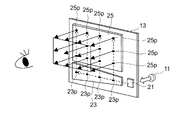
- FIG. 1 is a schematic diagram showing the configuration of the light guide 13.
- An optical system used in a head-mounted display (hereinafter referred to as HMD) or the like uses a so-called pupil-extending light guide 13 .
- the pupil expansion type light guide 13 includes a coupling region 21 that receives the image light from the display unit 11 and changes the direction of travel, a first expansion region 23 that expands the light flux incident in the first direction, and a second and a second expansion region 25 for expanding the light flux incident in two directions.
- the first direction and the second direction may intersect each other, eg, be orthogonal.
- the coupling region 21, the first expansion region 23, and the second expansion region 25 each have diffraction power for diffracting image light, and are formed as embossed holograms or volume holograms.
- An embossed hologram is, for example, a diffraction grating.
- a volume hologram is, for example, a periodic refractive index distribution within a dielectric film.
- the coupling region 21 changes the traveling direction of the image light incident from the outside so that it is directed toward the first expansion region 23 by diffraction power.
- the first expansion region 23 is provided with, for example, a diffraction structure element, and divides incident image light into image light traveling in the first direction and image light traveling to the second expansion region 25 by diffraction power. to duplicate the image light.
- a diffraction structure element For example, in FIG. 1, in the first extended region 23, the diffractive structure elements are arranged at four points 23p aligned in the direction in which the image light travels through repeated total reflection. A diffractive structure element splits the image light at each point 23 p and causes the split image light to travel to the second extension region 25 . As a result, the incident image light flux is expanded by being duplicated into four image light fluxes in the first direction.
- the second expansion region 25 is provided with, for example, a diffraction structure element, and divides the incident image light into image light traveling in the second direction due to diffraction power and image light emitted from the second expansion region 25 to the outside.
- the image light is duplicated by dividing into .
- three points 25p arranged in the direction in which the image light travels by repeating total reflection are arranged in each row, and a total of 12 points 25p in four rows each have a diffraction structure. elements are placed.
- the image light is split at each point 25p, and the split image light is emitted to the outside.
- the light guide 13 can duplicate 12 image light beams from one incident image light beam, and duplicate the light beams in the first direction and the second direction, respectively. can be used to extend the viewing area.
- the observer can visually recognize each of the 12 image light beams as a virtual image, and the visual recognition area in which the image light can be visually recognized by the observer can be widened.
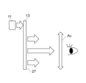
- FIG. 2 is an explanatory diagram showing incident light and outgoing light of the HMD.
- FIG. 3 is an explanatory diagram showing incident light and outgoing light of the HUD.
- the light guide 13 in the HMD is substantially facing the visual recognition area Ac in which the virtual image can be visually recognized by the observer.
- the image light vertically incident from the display unit 11 is split within the light guide 13, and the split image light is emitted from the emission surface 27 of the light guide 13 perpendicularly toward the visual recognition area Ac.
- the image light emitted from the light guide 13 is reflected by the windshield 5, for example, and enters the visual recognition area Ac, so that divided image light is guided.
- the light is emitted obliquely from the emission surface 27 of the light body 13 .
- the optical system for HUD will be described below.
- FIG. 4 is a cross-sectional view of a vehicle 3 equipped with a HUD system 1 according to the present disclosure.
- FIG. 5A is an explanatory diagram showing optical paths of light beams emitted from the display section.
- a HUD system 1 mounted on a vehicle 3 will be described as an example.
- the Z1-axis direction is the direction in which the observer visually recognizes the virtual image Iv from the visual recognition area Ac in which the observer can visually recognize the virtual image Iv.
- the X1-axis direction is a horizontal direction perpendicular to the Z1-axis.
- the Y1-axis direction is a direction orthogonal to the X1Z1 plane formed by the X1-axis and the Z1-axis.
- the X1-axis direction corresponds to the horizontal direction of the vehicle 3
- the Y1-axis direction corresponds to the substantially vertical direction of the vehicle 3
- the Z1-axis direction corresponds to the substantially forward direction of the vehicle 3 .
- the optical system 2 is arranged inside the dashboard (not shown) below the windshield 5 of the vehicle 3 .
- An observer D sitting in the driver's seat of the vehicle 3 recognizes the image projected from the HUD system 1 as a virtual image Iv.
- the HUD system 1 displays the virtual image Iv superimposed on the real scene visible through the windshield 5 . Since a plurality of duplicated images are projected in the visual recognition area Ac, the virtual image Iv can be visually recognized within the visual recognition area Ac even if the eye position of the observer D is deviated in the Y1-axis direction and the X1-axis direction. can be done.
- the angle ⁇ h indicating the horizontal viewing angle of the virtual image Iv viewed by the observer D is shown in FIG. ⁇ v is shown in FIG. 5C.
- the observer D is a passenger riding in a moving object such as the vehicle 3, for example, a passenger sitting in a driver's seat or a passenger's seat.
- a HUD system 1 comprises an optical system 2 and a windshield 5 .
- the optical system 2 includes a display section 11 , a light guide 13 and a control section 15 .
- the display unit 11 emits a luminous flux L1 that forms an image visually recognized by an observer as a virtual image Iv.
- the light guide 13 divides and copies the light beam L1 emitted from the display unit 11 and guides the duplicated light beam L2 to the windshield 5 .
- the luminous flux L2 reflected by the windshield 5 is superimposed on the actual scene visible through the windshield 5 and displayed as a virtual image Iv.
- the display unit 11 displays an image based on control by an external control unit.
- a liquid crystal display device with a backlight, an organic light-emitting diode display, a plasma display, or the like can be used.
- an image may be generated using a screen that diffuses or reflects light, a projector, or a scanning laser.
- the display unit 11 can display image contents including various information such as a road progress guide display, a distance to a vehicle in front, the remaining battery level of the vehicle, and the current vehicle speed. In this way, the display unit 11 emits a light flux L1 including image content that is visually recognized by the observer D as the virtual image Iv.
- the control unit 15 can be realized by a circuit made up of a semiconductor element or the like.
- the control unit 15 can be configured by, for example, a microcomputer, CPU, MPU, GPU, DSP, FPGA, or ASIC.
- the control unit 15 reads data and programs stored in a built-in storage unit (not shown) and performs various arithmetic processing, thereby realizing predetermined functions.
- the control unit 15 includes a storage device 17 .
- the storage device 17 is a storage medium that stores programs and data necessary for realizing the functions of the control unit 15 .
- the storage device 17 can be implemented by, for example, a hard disk (HDD), SSD, RAM, DRAM, ferroelectric memory, flash memory, magnetic disk, or a combination thereof.
- the storage device 17 stores a plurality of image data representing the virtual image Iv.
- the control unit 15 determines the virtual image Iv to be displayed based on vehicle-related information acquired from the outside.
- the control unit 15 reads the image data of the determined virtual image Iv from the storage unit and outputs it to the display unit 11 .
- FIG. 6 is a see-through perspective view showing the structure of the light guide 13. As shown in FIG. The directions for the extended area of the light guide 13 will be described below based on the X-axis, Y-axis and Z-axis shown in FIG. Let the normal direction to the surface of the light guide 13 at the center or the center of gravity of the first expansion region 23 be the Z-axis direction, and let the tangential plane be the XY plane.
- the traveling direction of the central ray of the light flux incident on the first expansion region 23 is defined as the X-axis direction, and the direction perpendicular to the X-axis direction is defined as the Y-axis direction.
- the normal direction to the surface of the light guide 13 at the center or the center of gravity of the second expansion region 25 be the Za-axis direction
- the tangential plane be the XaYa plane.
- the traveling direction of the central ray of the light flux incident on the second extended region is defined as the Xa-axis direction
- the direction perpendicular to the Xa-axis direction is defined as the Ya-axis direction.
- the light guide 13 has a first main surface 13a and a second main surface 13b.
- the first main surface 13a and the second main surface 13b face each other.
- the lightguide 13 has an entrance surface 20 , a coupling area 21 , a first extension area 23 , a second extension area 25 and an exit surface 27 .
- the entrance surface 20, the coupling region 21, the first extension region 23, and the second extension region 25 are included in the second major surface 13b, and the exit surface 27 is included in the first major surface 13a.
- the exit surface 27 faces the second extended region 25 .
- the coupling region 21, the first extension region 23, and the second extension region 25 may exist between the first major surface 13a and the second major surface 13b.
- the first principal surface 13 a faces the windshield 5 .
- incident surface 20 is included in coupling region 21 in the present embodiment, incident surface 20 may be included in first main surface 13a, which is a surface facing coupling region 21 .
- the output surface 27 may be included in the second extended region 25 .
- the coupling region 21, the first extension region 23, and the second extension region 25 have different diffraction powers, and form diffraction structure elements, respectively.
- the coupling region 21, the first expansion region 23, and the second expansion region 25 have different diffraction angles of the image light.
- the light guide 13 is configured such that the incident light flux is totally reflected inside.
- the light guide 13 is made of, for example, a glass or resin plate having a mirror-finished surface.
- the light guide 13 may have a curved shape instead of a planar shape.
- the light guide 13 partially includes a diffractive structure element such as a volume hologram that diffracts light.
- the combined area 21, the first extended area 23, and the second extended area 25 are three-dimensional areas when they contain volume holograms.
- the coupling area 21 is an area where the light beam L1 emitted from the display section 11 is incident from the incident surface 20 and changes the traveling direction of the light beam L1.
- the coupling region 21 has diffraction power, changes the propagating direction of the incident light flux L1 to the direction of the first expansion region 23, and emits the light flux L1A.
- coupling is a state in which light propagates through light guide 13 under the condition of total reflection.
- the first expansion area 23 expands the luminous flux L1A in a first direction corresponding to the horizontal direction of the virtual image Iv and emits it to a second expansion area in a second direction intersecting the first direction.
- the length in the first direction is greater than the length in the second direction.
- the light guide 13 is arranged so that the first direction is the horizontal direction (the direction of the X1 axis). They don't have to match.
- the luminous flux L1A propagated from the coupling region 21 propagates in the first direction while repeating total reflection on the first principal surface 13a and the second principal surface 13b, and spreads through the first extended region 23 formed on the second principal surface 13b.
- the diffractive structure duplicates the luminous flux L1 and emits it to the second expansion region 25 .
- the second expansion area 25 expands the light flux L1B in a second direction corresponding to the vertical direction of the virtual image Iv and emits the expanded light flux L2 from the emission surface 27.
- the second direction is, for example, perpendicular to the first direction.
- the second direction of the light guide 13 is arranged in the Z1-axis direction.
- the light beam L1B propagated from the first extension region 23 repeats total reflection at the first main surface 13a and the second main surface 13b, propagates in the second direction, and reaches the second main surface 13b formed on the second main surface 13b.
- the diffractive structure of the extended region 25 duplicates the light beam L1B and emits it to the outside of the light guide 13 through the exit surface 27.
- the light guide 13 directs the luminous flux L1, which is incident on the incident surface 20 and whose traveling direction is changed, in the horizontal direction (the direction of the X1 axis) of the virtual image Iv visually recognized by the observer D.
- the virtual image Iv is expanded by duplicating it in the vertical direction (the direction of the Y1 axis)
- the virtual image Iv is further expanded by duplication, and the luminous flux L2 is emitted from the exit surface 27 .
- duplication in the horizontal direction of an image is not limited to duplication only in the complete horizontal direction, but includes duplication in the substantially horizontal direction.
- duplication in the vertical direction of an image is not limited to duplication only in the complete vertical direction, but includes duplication in the substantially vertical direction.
- FIG. 7 is an explanatory diagram showing the optical path of the center of the light flux emitted from the display section.
- the luminous flux L1 of the image light incident on the light guide 13 is propagated to the first expansion region 23 that expands the pupil in the horizontal direction (X-axis direction) as the first direction by the diffraction structure formed in the coupling region 21. change. Therefore, after being obliquely incident on the coupling region 21, the light beam L1 propagates in the direction of the first expansion region 23 as the light beam L1A under the action of the wave vector k1 shown in FIG.
- the light flux L1A propagating to the first expansion region 23 extending in the first direction is duplicated with the light flux L1A propagating in the first direction by the diffraction structure formed in the first expansion region 23 while repeating total reflection. and a light flux L1B that changes its propagation direction to the second extension region 25.
- the duplicated light flux L1B propagates toward the second extension region 25 under the action of the wave vector k2 shown in FIG.
- the light beam L1B whose propagation direction is changed to the second expansion region 25 extending along the negative direction of the Z1 axis as the second direction propagates in the second direction by the diffraction structure formed in the second expansion region 25. and a beam L2 that is duplicated and emitted from the second expansion region 25 to the outside of the light guide 13 via the exit surface 27 .
- the duplicated light flux L2 propagates in the direction of the exit surface 27 under the action of the wave vector k3 shown in FIG.
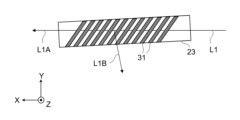
- FIGS. 8 and 9 are plan views of the first expansion region 23 and FIG. 9 are cross-sectional views taken along line IX-IX in FIG.
- the first extended region 23 has interference fringes 31 formed as the diffraction structure.
- ⁇ be the angle between the direction in which the interference fringes 31 extend in the XY plane and the traveling direction of the light beam L1A in the first expansion region 23 .
- ⁇ be the angle of inclination of the interference fringes 31 with respect to the vertical direction in the cross-sectional view of the diffraction structure in the vertical direction, that is, in the cross-sectional view taken along arrows IX-IX in FIG.
- the light flux L1A propagating to the first expansion region 23 extending in the first direction propagates in the first direction by the diffraction structure formed in the first expansion region 23 while repeating total reflection. It is split into a beam L1A and a beam L1B that is duplicated and redirected to the second extension region 25 .
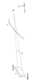
- FIG. 11 shows, in a spherical coordinate system, the duplicated light flux L1B when the light flux L1A is transmitted through the XY plane of the first extended region 23 from the negative direction to the positive direction of the Z axis.
- the viewing angle of the virtual image Iv viewed by the observer D is ⁇ F degrees
- the angle of the central ray of the light flux L1A with respect to the Z axis is ⁇ A degrees
- the angle of the central ray of the light flux L1B with respect to the Z axis is ⁇ B degrees
- the following It satisfies the formulas (1) and (2).
- the horizontal viewing angle of the virtual image Iv is 2 ⁇
- ⁇ h
- the vertical viewing angle of the virtual image Iv is 2 ⁇
- ⁇ v (see FIGS. 5B and 5C).
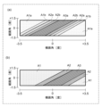
- FIG. FIG. 12 is a table of parameters in each example and comparative example.
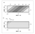
- 13 to 21 show diffraction efficiencies at viewing angles in each example and comparative example.
- FIGS. 13(a) to 21(a) show the diffraction of the light beam L1B replicated when the light beam L1A is transmitted through the first expansion region 23 from the negative direction to the positive direction of the Z-axis under each condition. Demonstrate efficiency.
- FIGS. 13(b) to 21(b) show the diffraction of the light beam L1B replicated when the light beam L1A is transmitted through the first expansion region 23 from the positive direction to the negative direction of the Z-axis under each condition. Demonstrate efficiency.
- the thickness of the volume hologram is 5 ⁇ m.
- Example 1 to Comparative Example 2 the viewing angle F is all 3.50 degrees.
- the viewing angle F in Example 1 to Comparative Example 2 indicates the angle of view (horizontal angle of view) in the horizontal direction (horizontal direction).
- the angles ⁇ A and ⁇ B described in relation to formulas (1) and (2) are 50.00 degrees, and the angle ⁇ is 45.00 degrees.
- the inclination angle ⁇ is 1.24 degrees.
- FIG. 13(c) shows the diffraction efficiency of the light flux L1B that has made one round trip in the first extended region 23 about the Z axis. That is, FIG.
- 13C shows the diffraction efficiency of the light beam L1B that is replicated when it is transmitted through the first expansion region 23 from the negative direction of the Z axis to the positive direction, and the diffraction efficiency from the positive direction of the Z axis to the negative direction.
- Diffraction efficiency obtained by summing the diffraction efficiencies of the light beam L1B that is duplicated when transmitted through the .
- the diffraction efficiency is shown in stages from levels A1 to A5, and the diffraction efficiency increases as the level A1 to A4 increases.
- Level A1 shows a diffraction efficiency of 0% or more and less than 10%
- level A2 shows a diffraction efficiency of 10% or more and less than 20%
- level A3 shows a diffraction efficiency of 20% or more and less than 30%
- level A4 shows a diffraction efficiency of 30%. Diffraction efficiencies greater than or equal to less than 40% are shown.
- Example 1 According to Example 1, ⁇ 0 and the equations (1) and (2) are satisfied. Therefore, as shown in FIGS. It exists separately, and high diffraction efficiency can be obtained in a wide range. Thereby, the effect of widening the angle of view can be obtained.
- the angle ⁇ A is 49.00 degrees
- the angle ⁇ B is 50.00 degrees
- the angle ⁇ is 44.57 degrees
- the inclination angle ⁇ is 0.71 degrees.
- ⁇ 0 which satisfies the equations (1) and (2).
- the diffraction efficiency of the light flux L1B that is replicated when it passes through the first expansion region 23 from the negative direction of the Z axis to the positive direction is high at the center of the angle of view. . Further, as shown in FIG.
- the diffraction efficiency of the light beam L1B that is replicated when it is transmitted through the first expansion region 23 from the positive direction of the Z axis to the negative direction is higher on the right side of the angle of view. ing. Since the peak positions of the respective diffraction efficiencies are separated in this manner, the effect of widening the angle of view can be obtained.
- Example 3 In the case of Example 3 shown in FIG. 16, the angle ⁇ A is 59.00 degrees, the angle ⁇ B is 60.00 degrees, the angle ⁇ is 44.71 degrees, and the inclination angle ⁇ is 0.71 degrees. . According to Example 3, ⁇ 0, which satisfies the equations (1) and (2).
- level A1a shows a diffraction efficiency of 0% or more and less than 5%
- level A1b shows a diffraction efficiency of 5% or more and less than 10%
- level A2a shows a diffraction efficiency of 10% or more and less than 15%.
- Level A2b indicates a diffraction efficiency of 15% or more and less than 20%
- Level A3a indicates a diffraction efficiency of 20% or more and less than 25%.
- the diffraction efficiency of the light flux L1B that is replicated when it passes through the first expansion region 23 from the negative direction of the Z axis to the positive direction is high at the center of the angle of view.
- the diffraction efficiency of the light flux L1B that is replicated when it is transmitted through the first expansion region 23 from the positive direction of the Z axis to the negative direction is higher on the right side of the angle of view. ing. Since the peak positions of the respective diffraction efficiencies are separated in this manner, the effect of widening the angle of view can be obtained.
- Example 4 In the case of Example 4 shown in FIG. 17, the angle ⁇ A is 59.00 degrees, the angle ⁇ B is 58.50 degrees, the angle ⁇ is 50.76 degrees, and the inclination angle ⁇ is ⁇ 0.32 degrees. be. According to Example 4, ⁇ 0, which satisfies the equations (1) and (2). As shown in FIG. 17A, the diffraction efficiency of the light beam L1B that is replicated when it passes through the first expansion region 23 from the negative direction of the Z axis to the positive direction is high at the center of the angle of view. . Further, as shown in FIG.
- the diffraction efficiency of the light beam L1B that is replicated when it is transmitted through the first expansion region 23 from the positive direction of the Z axis to the negative direction is higher on the left side of the angle of view. ing. Since the peak positions of the respective diffraction efficiencies are separated in this manner, the effect of widening the angle of view can be obtained.
- the angle ⁇ A is 59.00 degrees
- the angle ⁇ B is 59.55 degrees
- the angle ⁇ is 34.85 degrees
- the inclination angle ⁇ is 0.48 degrees.
- level A5 indicates a diffraction efficiency of 40% or more and less than 50%.
- the diffraction efficiency of the light flux L1B that is replicated when it passes through the first expansion region 23 from the negative direction of the Z axis to the positive direction is high at the center of the angle of view. . Further, as shown in FIG.
- the diffraction efficiency of the light flux L1B that is replicated when it is transmitted through the first expansion region 23 from the positive direction of the Z axis to the negative direction is higher on the right side of the angle of view. ing. Since the peak positions of the respective diffraction efficiencies are separated in this manner, the effect of widening the angle of view can be obtained.
- level A1c indicates a diffraction efficiency of 0% or more and less than 2%
- level A1d indicates a diffraction efficiency of 2% or more and less than 4%
- level A1e indicates a diffraction efficiency of 4% or more and less than 6%
- level A1f shows a diffraction efficiency of 6% or more and less than 8%
- level A1g shows a diffraction efficiency of 8% or more and less than 10%.
- Example 6 although ⁇ 0, the equations (1) and (2) are not satisfied. Therefore, as shown in FIGS. 19(a) and 19(b), when transmitting through the first extended region 23 from the positive direction of the Z axis and when transmitting from the negative direction, each Since the positions of the diffraction efficiency peaks are different, the effect of widening the angle of view can be obtained. However, since the equations (1) and (2) are not satisfied, there is a diffraction efficiency peak outside the angle of view, and as shown in FIG. The diffraction efficiency within the angle of view of the light flux L1B that is duplicated when transmitted from the direction of ⁇ in the negative direction is low, and the effect of enlarging the angle of view is smaller than in Examples 1-5.
- Example 7 In the case of Example 7 shown in FIG. 20, the angle ⁇ A is 50.00 degrees, the angle ⁇ B is 53.00 degrees, the angle ⁇ is 43.81 degrees, and the inclination angle ⁇ is 2.12 degrees. .
- the equations (1) and (2) are not satisfied. Therefore, as shown in FIGS. 20(a) and 20(b), when the first extended region 23 is transmitted from the positive direction of the Z-axis and when transmitted from the negative direction, each Since the positions of the diffraction efficiency peaks are different, the effect of widening the angle of view can be obtained. However, since the equations (1) and (2) are not satisfied, as shown in FIG. The diffraction efficiency within the angle of view of the light flux L1B is low, and the effect of enlarging the angle of view is smaller than in Examples 1-5.
- FIG. 22 is a graph showing an example of normalized diffraction efficiency when the thickness T in formula (3) is near the lower limit.
- the diffraction efficiency may become zero within the range of the viewing angle. As a result, a part of the image is lost and the quality deteriorates.
- the thickness of the volume hologram that satisfies the relationship of the formula (3) can be adopted.
- FIG. 23 is a graph showing an example of normalized diffraction efficiency when the thickness T in formula (4) is near the upper limit.
- the diffraction efficiency becomes zero or more within the half range of the viewing angle.
- the range in which the diffraction efficiency is greater than or equal to zero becomes too narrow. Since the diffraction efficiency is improved by the form of , an image can be displayed over the entire viewing angle range.
- the second expansion region 25 also has a structure similar to the diffraction structure of the first expansion region 23 . Only one of the first expansion region 23 and the second expansion region 25 may have such a structure, or the optical system 2 may have a further expansion region, and the other expansion region may have such diffractive structures. Also, the functions of the first expansion region 23 and the second expansion region 25 may be realized by one expansion region. can be replicated horizontally and vertically.
- the optical system 2 of the present disclosure includes a display unit 11 that emits a luminous flux L1 that is visually recognized by an observer D as a virtual image Iv, and a light guide 13 that replicates the luminous flux L1.
- the light guide 13 has an incident surface 20 on which the light flux L1 from the display section 11 is incident, and an exit surface 27 from which the light flux L2 is emitted from the light guide 13 .
- a central ray of the light beam L1 emitted from the display unit 11 is incident on the incident surface 20 of the light guide 13 .
- the light beam L ⁇ b>1 incident on the incident surface 20 of the light guide 13 is diffracted by the diffraction structure of the coupling region in the light guide 13 to change its traveling direction.
- the luminous flux whose traveling direction has been changed corresponds to the first direction corresponding to the horizontal direction of the virtual image Iv visually recognized by the observer D through diffraction by the diffraction structure of the extended region in the light guide 13, or to the vertical direction of the virtual image Iv.
- the light is emitted from the exit surface 27 after being expanded by duplication in the second direction or both directions.
- the normal direction to the surface of the light guide 13 at the center or the center of gravity of the expansion area is the Z-axis direction, and the tangential plane is the XY plane.
- the traveling direction of the central ray of the light beam L1A is the X axis
- the direction perpendicular to the X axis is the Y axis.
- the duplicated light flux L1B when transmitted from the positive direction of and the duplicated light flux L1B when transmitted from the negative direction of the Z axis are formed so as to be accommodated in the viewing angle where the virtual image can be viewed,
- the diffractive structures in the extended region are tilted with respect to the Z-axis direction.
- the diffractive structure of the expansion region is inclined with respect to the Z-axis direction, the light beam L1B that is duplicated when the light beam L1A is transmitted through the XY plane of the expansion region from the positive direction of the Z-axis and the negative light beam L1B of the Z-axis.
- the respective peaks of the diffraction efficiencies of the duplicated light flux L1B when transmitted from different directions can be formed at different positions within the viewing angle. Therefore, it is possible to provide an optical system with an enlarged visual field range in which a virtual image can be seen.
- a virtual image Iv suitable for the observer D who drives the vehicle 3 can be displayed.
- the diffraction structure of the extended region is interference fringes, but it is not limited to this.
- a physical concave-convex structure filled with resin may be used.
- the divided and duplicated luminous flux L2 is reflected by the windshield 5 to allow the observer D to visually recognize the virtual image Iv, but the present invention is not limited to this.
- a combiner may be used instead of the windshield 5, and the split-copied light beam L2 may be reflected by the combiner to allow the observer D to visually recognize the virtual image Iv.
- the first direction in which the light beam L1A is expanded in the first expansion region 23 and the second direction in which the light beam L1B is expanded in the second expansion region 25 are orthogonal to each other, but the invention is not limited to this.
- the light beam L1A is expanded in the first direction by the first expansion region 23 if the expansion component in the horizontal direction is larger than that in the direction along the Z axis.
- Expansion of the light flux L1B in the second direction at 25 may be achieved if the expansion component in the direction along the Z-axis is larger than that in the horizontal direction.
- the object to which the HUD system 1 is applied is not limited to the vehicle 3 .
- Objects to which the HUD system 1 is applied may be, for example, trains, motorcycles, ships, or aircraft, or may be amusement machines that do not involve movement.
- the light flux from the display section 11 is reflected by a transparent curved plate as a translucent member that reflects the light flux emitted from the display section 11.
- FIG. the actual scene that the user can visually recognize through the transparent curved plate may be an image displayed from another image display device. That is, the virtual image by the HUD system 1 may be superimposed on the video displayed from another video display device.
- any one of the windshield 5, the combiner, and the transparent curved plate may be employed as the translucent member in the present disclosure.
- optical system 2 is used in the HUD system 1 that displays the virtual image Iv in the above embodiment, it is not limited to this.
- the optical system 2 may be used, for example, in an image display system in which an observer directly observes a light beam emitted from the exit surface 27 instead of viewing a virtual image through a translucent member.
- the observer is a person who directly sees the image formed by the emitted light flux, and is not limited to the passenger of the mobile object.
- An optical system includes a display unit that emits a light flux that is viewed by an observer as an image, and a light guide that replicates the light flux.
- the light guide has an incident surface on which the light flux from the display section is incident and an exit surface from which the light flux exits from the light guide.
- a light beam at the center of the light flux emitted from the display portion enters the incident surface of the light guide.
- a luminous flux incident on the incident surface of the light guide has its traveling direction changed by diffraction caused by the diffractive structure of the coupling region in the light guide.
- the luminous flux whose traveling direction has been changed is diffracted by the diffraction structure of the extended region in the light guide in a first direction corresponding to the horizontal direction of the virtual image visually recognized by the observer, or in a second direction corresponding to the vertical direction of the image. , or after being expanded by being duplicated in both directions, is emitted from the exit surface.
- the direction normal to the surface of the light guide at the center or center of gravity of the expansion area is the Z-axis direction
- the tangential plane is the XY plane.
- the diffractive structure of the extended region is composed of a light beam that is duplicated when the light beam incident on the extended region is transmitted through the XY plane of the extended region from the positive direction of the Z axis, and the Z axis
- the diffractive structures in the extended region are formed to be contained in the viewing angle at which the image is visible when transmitted from the negative direction of .
- the diffractive structure of the extended region is tilted with respect to the Z-axis direction, when the light beam incident on the extended region is transmitted through the XY plane of the extended region from the positive direction of the Z-axis, the duplicated light beam and the Z-axis When transmitted from the negative direction of , the respective peaks of the diffraction efficiencies of the duplicated beams can be formed at different positions within the viewing angle. Therefore, it is possible to provide an optical system with an enlarged visual field range in which an image can be seen.
- the viewing angle of the image seen by the observer is ⁇ F degrees
- the angle between the diffraction structure of the extended region in the XY plane and the traveling direction of the light flux incident on the extended region is ⁇
- the tilt angle between the diffractive structure and the Z axis is ⁇ degrees
- the angle between the central ray of the light beam incident on the expansion region and the Z axis is ⁇ A degrees
- the light beam diffracted in the expansion region is emitted.
- the optical system has two expansion regions, and one expansion region corresponds to the horizontal direction of the image visually recognized by the observer.
- the other expansion area duplicates the light beam incident on the other expansion area in a second direction corresponding to the vertical direction of the virtual image visually recognized by the observer. Expand.
- the relational expression is satisfied in the expansion region in which the diffraction pitch of the diffraction structure is narrower in the two expansion regions.
- the extended area includes a transmission volume hologram.
- the thickness T of the volume hologram in the Z direction and the wavelength ⁇ [ ⁇ m] of the light flux incident on the volume hologram satisfy the following relational expression. T>( ⁇ 2.3576 ⁇ +0.0952) ⁇
- the thickness T of the volume hologram in the Z direction and the wavelength ⁇ [ ⁇ m] of the light beam incident on the volume hologram satisfy the following relational expression. T ⁇ ( ⁇ 3.8645 ⁇ 0.2185) ⁇
- the central ray of the light beam emitted from the display unit is incident at an angle to the normal direction of the incident surface of the light guide, and is guided.
- a light beam at the center of the light flux emitted from the light body is inclined with respect to the normal line direction of the emission surface of the light guide and emitted toward the translucent member.
- a head-up display system of the present disclosure includes an optical system according to any one of (1) to (8), and a light-transmitting member that reflects a light beam emitted from a light guide, wherein the light-transmitting member An image is superimposed as a virtual image on a real scene that can be visually recognized through the .
- the translucent member is the windshield of the moving body.
- the present disclosure is applicable to an optical system and a head-up display system that replicate and display images.
Landscapes
- Physics & Mathematics (AREA)
- Engineering & Computer Science (AREA)
- General Physics & Mathematics (AREA)
- Optics & Photonics (AREA)
- Chemical & Material Sciences (AREA)
- Combustion & Propulsion (AREA)
- Transportation (AREA)
- Mechanical Engineering (AREA)
- Diffracting Gratings Or Hologram Optical Elements (AREA)
Priority Applications (4)
| Application Number | Priority Date | Filing Date | Title |
|---|---|---|---|
| JP2023538275A JP7784640B2 (ja) | 2021-07-30 | 2022-03-30 | 光学系及びそれを備えたヘッドアップディスプレイシステム |
| EP22848946.4A EP4379451A4 (en) | 2021-07-30 | 2022-03-30 | OPTICAL SYSTEM AND HEAD-UP DISPLAY SYSTEM |
| CN202280052597.7A CN117716275A (zh) | 2021-07-30 | 2022-03-30 | 光学系统以及具备其的平视显示器系统 |
| US18/422,745 US20240160015A1 (en) | 2021-07-30 | 2024-01-25 | Optical system and head-up display system comprising same |
Applications Claiming Priority (2)
| Application Number | Priority Date | Filing Date | Title |
|---|---|---|---|
| JP2021125659 | 2021-07-30 | ||
| JP2021-125659 | 2021-07-30 |
Related Child Applications (1)
| Application Number | Title | Priority Date | Filing Date |
|---|---|---|---|
| US18/422,745 Continuation US20240160015A1 (en) | 2021-07-30 | 2024-01-25 | Optical system and head-up display system comprising same |
Publications (1)
| Publication Number | Publication Date |
|---|---|
| WO2023007863A1 true WO2023007863A1 (ja) | 2023-02-02 |
Family
ID=85087808
Family Applications (1)
| Application Number | Title | Priority Date | Filing Date |
|---|---|---|---|
| PCT/JP2022/016242 Ceased WO2023007863A1 (ja) | 2021-07-30 | 2022-03-30 | 光学系及びそれを備えたヘッドアップディスプレイシステム |
Country Status (5)
| Country | Link |
|---|---|
| US (1) | US20240160015A1 (https=) |
| EP (1) | EP4379451A4 (https=) |
| JP (1) | JP7784640B2 (https=) |
| CN (1) | CN117716275A (https=) |
| WO (1) | WO2023007863A1 (https=) |
Citations (7)
| Publication number | Priority date | Publication date | Assignee | Title |
|---|---|---|---|---|
| US20140300966A1 (en) * | 2011-08-29 | 2014-10-09 | Vuzix Corporation | Controllable waveguide for near-eye display applications |
| WO2018198587A1 (ja) | 2017-04-28 | 2018-11-01 | ソニー株式会社 | 光学装置、画像表示装置及び表示装置 |
| US10429645B2 (en) | 2015-10-07 | 2019-10-01 | Microsoft Technology Licensing, Llc | Diffractive optical element with integrated in-coupling, exit pupil expansion, and out-coupling |
| JP2019184920A (ja) * | 2018-04-13 | 2019-10-24 | 株式会社デンソー | ヘッドアップディスプレイ装置 |
| US20200257065A1 (en) * | 2019-02-11 | 2020-08-13 | Facebook Technologies, Llc | Dispersion compensation for light coupling through slanted facet of optical waveguide |
| US20200264429A1 (en) * | 2019-02-14 | 2020-08-20 | Thales | Viewing device comprising a pupil expander including two mirrors |
| US20200341280A1 (en) * | 2017-08-18 | 2020-10-29 | EARDG Photonics, Inc. | Waveguide image combiners for augmented reality displays |
Family Cites Families (6)
| Publication number | Priority date | Publication date | Assignee | Title |
|---|---|---|---|---|
| US9791703B1 (en) * | 2016-04-13 | 2017-10-17 | Microsoft Technology Licensing, Llc | Waveguides with extended field of view |
| EP3548939A4 (en) * | 2016-12-02 | 2020-11-25 | DigiLens Inc. | UNIFORM OUTPUT LIGHTING WAVEGUIDE DEVICE |
| CN110383117A (zh) * | 2017-01-26 | 2019-10-25 | 迪吉伦斯公司 | 具有均匀的输出照明的波导设备 |
| JP6980209B2 (ja) * | 2017-02-22 | 2021-12-15 | ルムス エルティーディー. | 光ガイド光学アセンブリ |
| US11105982B2 (en) * | 2019-05-30 | 2021-08-31 | Facebook Technologies, Llc | Imageable overcoat for an optical waveguide and process for making the same |
| US20210055551A1 (en) * | 2019-08-23 | 2021-02-25 | Facebook Technologies, Llc | Dispersion compensation in volume bragg grating-based waveguide display |
-
2022
- 2022-03-30 WO PCT/JP2022/016242 patent/WO2023007863A1/ja not_active Ceased
- 2022-03-30 EP EP22848946.4A patent/EP4379451A4/en active Pending
- 2022-03-30 JP JP2023538275A patent/JP7784640B2/ja active Active
- 2022-03-30 CN CN202280052597.7A patent/CN117716275A/zh active Pending
-
2024
- 2024-01-25 US US18/422,745 patent/US20240160015A1/en active Pending
Patent Citations (7)
| Publication number | Priority date | Publication date | Assignee | Title |
|---|---|---|---|---|
| US20140300966A1 (en) * | 2011-08-29 | 2014-10-09 | Vuzix Corporation | Controllable waveguide for near-eye display applications |
| US10429645B2 (en) | 2015-10-07 | 2019-10-01 | Microsoft Technology Licensing, Llc | Diffractive optical element with integrated in-coupling, exit pupil expansion, and out-coupling |
| WO2018198587A1 (ja) | 2017-04-28 | 2018-11-01 | ソニー株式会社 | 光学装置、画像表示装置及び表示装置 |
| US20200341280A1 (en) * | 2017-08-18 | 2020-10-29 | EARDG Photonics, Inc. | Waveguide image combiners for augmented reality displays |
| JP2019184920A (ja) * | 2018-04-13 | 2019-10-24 | 株式会社デンソー | ヘッドアップディスプレイ装置 |
| US20200257065A1 (en) * | 2019-02-11 | 2020-08-13 | Facebook Technologies, Llc | Dispersion compensation for light coupling through slanted facet of optical waveguide |
| US20200264429A1 (en) * | 2019-02-14 | 2020-08-20 | Thales | Viewing device comprising a pupil expander including two mirrors |
Non-Patent Citations (1)
| Title |
|---|
| See also references of EP4379451A4 |
Also Published As
| Publication number | Publication date |
|---|---|
| CN117716275A (zh) | 2024-03-15 |
| JP7784640B2 (ja) | 2025-12-12 |
| EP4379451A1 (en) | 2024-06-05 |
| EP4379451A4 (en) | 2025-01-29 |
| US20240160015A1 (en) | 2024-05-16 |
| JPWO2023007863A1 (https=) | 2023-02-02 |
Similar Documents
| Publication | Publication Date | Title |
|---|---|---|
| US11143866B2 (en) | Waveguide including volume Bragg gratings | |
| CN113168003B (zh) | 用于增强现实设备中的高效目镜的方法和系统 | |
| US10989880B2 (en) | Waveguide grating with spatial variation of optical phase | |
| US20200117005A1 (en) | Waveguide for conveying multiple portions of field of view | |
| CN115667795A (zh) | 具有分区衍射光学器件的图像光导 | |
| US20240111152A1 (en) | Image display device and headup display system | |
| US12554134B2 (en) | Head-up display system | |
| US20230393392A1 (en) | Head-up display system | |
| JP7784640B2 (ja) | 光学系及びそれを備えたヘッドアップディスプレイシステム | |
| US20240160016A1 (en) | Optical system and head-up display system comprising same | |
| WO2024004288A1 (ja) | 光学系、及び、画像表示装置 | |
| JP2025510847A (ja) | 複数の波長範囲画像光ガイドシステム | |
| US20250020916A1 (en) | Optical system and head-up display system including same | |
| US20250130424A1 (en) | Image display device and optical system | |
| WO2024004289A1 (ja) | 光学系、及び、画像表示装置 | |
| JP2023070440A (ja) | 回折素子及びそれを備えた光学系、ヘッドアップディスプレイシステム | |
| US20230236415A1 (en) | Image generation and delivery in a display system utilizing a two-dimensional (2d) field of view expander | |
| JP2025535963A (ja) | コンパクトな回折光学素子を有する画像光ガイド | |
| CN117761825A (zh) | 一种光波导器件及ar显示装置 |
Legal Events
| Date | Code | Title | Description |
|---|---|---|---|
| 121 | Ep: the epo has been informed by wipo that ep was designated in this application |
Ref document number: 22848946 Country of ref document: EP Kind code of ref document: A1 |
|
| WWE | Wipo information: entry into national phase |
Ref document number: 2023538275 Country of ref document: JP |
|
| WWE | Wipo information: entry into national phase |
Ref document number: 202280052597.7 Country of ref document: CN |
|
| WWE | Wipo information: entry into national phase |
Ref document number: 2022848946 Country of ref document: EP |
|
| NENP | Non-entry into the national phase |
Ref country code: DE |
|
| ENP | Entry into the national phase |
Ref document number: 2022848946 Country of ref document: EP Effective date: 20240229 |