WO2022270237A1 - ノズルプレート、液滴吐出ヘッド、液滴吐出装置及びノズルプレートの製造方法 - Google Patents
ノズルプレート、液滴吐出ヘッド、液滴吐出装置及びノズルプレートの製造方法 Download PDFInfo
- Publication number
- WO2022270237A1 WO2022270237A1 PCT/JP2022/021937 JP2022021937W WO2022270237A1 WO 2022270237 A1 WO2022270237 A1 WO 2022270237A1 JP 2022021937 W JP2022021937 W JP 2022021937W WO 2022270237 A1 WO2022270237 A1 WO 2022270237A1
- Authority
- WO
- WIPO (PCT)
- Prior art keywords
- nozzle
- nozzle plate
- taper
- substrate
- discharge channel
- Prior art date
- Legal status (The legal status is an assumption and is not a legal conclusion. Google has not performed a legal analysis and makes no representation as to the accuracy of the status listed.)
- Ceased
Links
Images






Classifications
-
- B—PERFORMING OPERATIONS; TRANSPORTING
- B41—PRINTING; LINING MACHINES; TYPEWRITERS; STAMPS
- B41J—TYPEWRITERS; SELECTIVE PRINTING MECHANISMS, i.e. MECHANISMS PRINTING OTHERWISE THAN FROM A FORME; CORRECTION OF TYPOGRAPHICAL ERRORS
- B41J2/00—Typewriters or selective printing mechanisms characterised by the printing or marking process for which they are designed
- B41J2/005—Typewriters or selective printing mechanisms characterised by the printing or marking process for which they are designed characterised by bringing liquid or particles selectively into contact with a printing material
- B41J2/01—Ink jet
- B41J2/135—Nozzles
- B41J2/14—Structure thereof only for on-demand ink jet heads
-
- B—PERFORMING OPERATIONS; TRANSPORTING
- B41—PRINTING; LINING MACHINES; TYPEWRITERS; STAMPS
- B41J—TYPEWRITERS; SELECTIVE PRINTING MECHANISMS, i.e. MECHANISMS PRINTING OTHERWISE THAN FROM A FORME; CORRECTION OF TYPOGRAPHICAL ERRORS
- B41J2/00—Typewriters or selective printing mechanisms characterised by the printing or marking process for which they are designed
- B41J2/005—Typewriters or selective printing mechanisms characterised by the printing or marking process for which they are designed characterised by bringing liquid or particles selectively into contact with a printing material
- B41J2/01—Ink jet
- B41J2/135—Nozzles
- B41J2/16—Production of nozzles
Definitions
- the present invention relates to a nozzle plate, a droplet ejection head, a droplet ejection device, and a method for manufacturing a nozzle plate.
- the circulation flow path is formed in the straight nozzle flow path that is substantially perpendicular to the droplet discharge surface of the nozzle plate.
- the meniscus of the liquid is drawn in more, and the shape of the meniscus tends to become unstable, resulting in unstable ejection. was there.
- the present invention has been made in view of such circumstances, and an object of the present invention is to provide a nozzle plate, a droplet ejection head, a droplet ejection device, and a nozzle plate that can stably eject droplets under a wider range of conditions regarding the amount of droplets and the ejection speed. It is to provide a manufacturing method.
- One aspect of the present invention that solves the above problems is a substrate, a nozzle channel that is provided through the substrate and has a nozzle opening that ejects droplets, and a discharge stream that discharges the liquid from the nozzle channel.
- a nozzle plate comprising a channel, the nozzle flow channel has a nozzle tapered portion in which a flow channel area, which is a cross-sectional area perpendicular to a droplet discharge direction, gradually narrows toward the discharge surface of the substrate from which droplets are discharged;
- the discharge channel is provided in the middle of the nozzle taper portion when viewed from the ejection surface side.
- the invention according to claim 2 is the nozzle plate according to claim 1,
- the shape of the nozzle taper portion is either pyramidal, conical or elliptical pyramidal.
- the invention according to claim 3 is the nozzle plate according to claim 1 or 2,
- the nozzle flow path includes a nozzle straight portion that is continuous with an end portion of the nozzle taper portion on the ejection surface side.
- the invention according to claim 4 is the nozzle plate according to claim 3, In the nozzle straight portion, the maximum portion of the flow passage area is equal to or smaller than the flow passage area of the end portion of the nozzle taper portion on the ejection surface side.
- the invention according to claim 5 is the nozzle plate according to any one of claims 1 to 4, A distance from the ejection surface to the discharge channel is 5 ⁇ m or more and 200 ⁇ m or less.
- a taper angle which is an angle between a slope of the nozzle taper portion and an axis parallel to the nozzle central axis, is 15° or more and 75° or less.
- the invention according to claim 7 is the nozzle plate according to claim 6,
- the taper angle is 30° or more and 60° or less.
- the invention according to claim 8 is the nozzle plate according to claim 6 or 7,
- the nozzle channel includes a plurality of continuous nozzle taper portions with different taper angles.
- the invention according to claim 9 is the nozzle plate according to any one of claims 1 to 8,
- the substrate is made of single crystal silicon
- the nozzle flow path has a straight communicating portion that is continuous with an end portion of the nozzle taper portion opposite to the ejection surface,
- the nozzle taper portion is formed of four ⁇ 111 ⁇ planes,
- the straight communication portion is formed of four ⁇ 100 ⁇ planes.
- the invention according to claim 10 is the nozzle plate according to claim 9,
- the discharge channel is formed so as to be positioned at a corner where two ⁇ 100 ⁇ planes of the straight communication portion intersect.
- the invention according to claim 11 is the nozzle plate according to claim 9 or 10,
- the discharge channel is formed so as to be positioned at the boundary between the adjacent nozzle taper portions.
- a droplet ejection head mounted in a droplet ejection device, A nozzle plate according to any one of claims 1 to 11 is provided.
- the invention according to claim 13 is a droplet discharge device, A droplet ejection head according to claim 12 is provided.
- the invention according to claim 14 is the liquid droplet ejection device according to claim 13,
- the drive frequency is 30 kHz or more and 100 kHz or less.
- the invention according to claim 15 is the droplet ejection device according to claim 13 or 14,
- the amount of liquid droplets ejected from the nozzle opening is 30 pL or more and 300 pL or less.
- a method for manufacturing a nozzle plate of a liquid droplet ejection head comprising: a first step of uniformly forming a surface mask layer on a first surface of a single-crystal silicon substrate having a ⁇ 100 ⁇ surface crystal orientation; a second step of forming a circular or polygonal opening pattern for nozzle openings in the surface mask layer; a third step of forming a through-hole by dry-etching through the substrate under the opening pattern from the surface; a fourth step of forming a nozzle taper portion by enlarging the through hole by anisotropic wet etching of the substrate; and a fifth step of forming a discharge passage by performing deep etching by dry etching up to the middle of the nozzle taper portion.
- the invention according to claim 17 is the method for manufacturing the nozzle plate according to claim 16,
- the substrate below the opening pattern is subjected to deep etching from the surface to the middle by dry etching to form a nozzle straight portion, A mask layer is formed on the side surface of the nozzle straight portion.
- the invention according to claim 18 is a method for manufacturing a nozzle plate according to claim 16 or 17, comprising: In the fourth step, the nozzle taper portion and the straight communication portion are formed by enlarging the through hole by anisotropic wet etching of the substrate.
- the invention according to claim 19 is the method for manufacturing the nozzle plate according to any one of claims 16 to 18,
- the surface mask layer is uniformly formed on a first surface of the substrate and a second surface facing the first surface
- the fifth step removes the discharge channel mask layer on the side and bottom surfaces of the discharge channel
- a nozzle plate a droplet ejection head, a droplet ejection device, and a method for manufacturing a nozzle plate, in which ejection is stable over a wider range of conditions regarding the droplet amount and ejection speed.
- FIG. 1 is a schematic perspective view of a droplet ejection device according to this embodiment
- FIG. 1 is a schematic side cross-sectional view of a droplet discharge head according to this embodiment
- FIG. 4 is an enlarged plan view showing nozzle flow paths of the nozzle plate according to the embodiment
- FIG. 3B is a cross-sectional view of the nozzle plate taken along line IIIB-IIIB of FIG. 3A
- FIG. It is an enlarged plan view showing a nozzle flow path of a nozzle plate according to a modification
- 4B is a cross-sectional view of the nozzle plate taken along line IVB-IVB of FIG. 4A
- FIG. It is an enlarged plan view showing a nozzle flow path of a nozzle plate according to a modification.
- FIG. 4 is a cross-sectional view of the nozzle plate showing main steps of the method of manufacturing the nozzle plate according to the first embodiment
- FIG. 8 is a cross-sectional view of a nozzle plate showing main steps of a method of manufacturing a nozzle plate according to the second embodiment
- FIG. 10 is a cross-sectional view of a nozzle plate showing main steps of a method of manufacturing a nozzle plate according to the third embodiment
- FIG. 4 is a cross-sectional view of a nozzle plate showing main steps of a nozzle plate manufacturing method including a step of forming a nozzle straight portion;
- FIG. 1 is a schematic perspective view showing an inkjet recording apparatus 1 according to this embodiment.
- the inkjet recording apparatus 1 conveys a recording medium P such as paper in the front-rear direction through a plurality of units U by a conveying section T including, for example, a conveying belt T1 and conveying rollers T2.
- a plurality of inkjet heads 10 are arranged in each unit U, and the ink of each color is ejected from each inkjet head 10 to perform printing on the recording medium P.
- the inkjet recording apparatus 1 according to this embodiment can stably eject liquid droplets even at a relatively wide range of driving frequencies from 10 kHz to 100 kHz. Further, the ink jet recording apparatus 1 according to the present embodiment can stably eject liquid droplets even in a relatively wide range of liquid droplet amounts from 10 pL to 300 pL.
- FIG. 2 is a schematic side cross-sectional view of one inkjet head 10 viewed from the side.
- the inkjet head 10 includes a head chip 11, a common ink chamber 12, a support substrate 13, a wiring member 14, a driving section 15, and the like. Note that FIG. 2 shows a cross section of the inkjet head 10 on a plane including four nozzle openings N, but detailed description of the nozzle flow paths 111 to be described later is omitted.
- the head chip 11 is configured to eject ink from the nozzle openings N.
- a plurality of (four in FIG. 2) plate-like substrates are laminated on the head chip 11 .
- the lowest plate in the head chip 11 is the nozzle plate 110 .
- a nozzle plate 110 is provided with a plurality of nozzle channels 111 (see FIG. 3B) having a structure according to the present invention. Then, ink is ejected from the nozzle opening portion N, which is the opening portion of the nozzle flow path 111, substantially perpendicularly to the ejection surface Ba, which is the exposed surface of the nozzle plate 110. As shown in FIG.
- a piezoelectric plate 120, a vibration plate 130, a spacer substrate 140, and a wiring substrate 150 are adhered in this order upward to the bonding surface Bb (see FIG. 3B), which is the surface facing the ejection surface Ba of the nozzle plate 110. It has been laminated.
- the piezoelectric plate 120, the vibration plate 130, the spacer substrate 140, and the wiring substrate 150 are provided with ink flow paths communicating with the nozzle openings N, and the exposed side (upward side) of the wiring substrate 150 is It is opened with A common ink chamber 12 is provided on the exposed surface of the wiring board 150 so as to cover all openings.
- Ink stored in an ink chamber forming member (not shown) of the common ink chamber 12 is supplied from the opening of the wiring board 150 to each nozzle opening N through the ink flow path.
- the pressure chamber provided to penetrate the piezoelectric plate 120 is deformed together with the diaphragm 130 by the displacement (deformation) of the piezoelectric element in the storage section adjacent to the pressure chamber, and the pressure change is applied.
- the ink is ejected downward from the nozzle opening N as droplets.
- FIG. 3A is an enlarged plan view showing one nozzle flow path 111 when the nozzle plate 110 is viewed from the bonding surface Bb side.
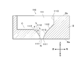
- 3B is a cross-sectional view showing one nozzle channel 111 taken along line IIIB-IIIB in FIG. 3A.
- the nozzle plate 110 includes a substrate B, a nozzle channel 111 having a nozzle opening N, and a discharge channel C continuous with the nozzle channel 111 .
- the substrate B is, for example, a plate member made of single crystal silicon (Si) having a thickness of about 100 ⁇ m to 725 ⁇ m.
- Si single crystal silicon
- the nozzle flow path 111 is a through hole penetrating from the ejection surface Ba of the substrate B to the bonding surface Bb.
- the nozzle flow path 111 includes a nozzle opening portion N, a nozzle straight portion 1111, a nozzle taper portion 1112, and a straight communication portion 1113 from the ejection surface Ba toward the bonding surface Bb.
- the nozzle openings N are holes that are circular or polygonal in shape.
- the nozzle openings N are arranged in a matrix on the side of the ejection surface Ba of the substrate B, and the side opposite to the ejection surface Ba communicates with the nozzle straight portion 1111 .
- the shape of the nozzle opening N may be circular or polygonal. If the shape of the nozzle opening N is circular, for example, the diameter can be about 15 ⁇ m to 45 ⁇ m.
- the nozzle straight portion 1111 is formed continuously with the end portion of the nozzle tapered portion 1112 on the ejection surface Ba side.
- the resistance applied when ink is ejected from the nozzle opening portion N increases, suppressing vibration of the meniscus, so that the shape of the meniscus can be further stabilized.
- the flow path area which is the cross-sectional area in the direction orthogonal to the ink ejection direction (horizontal direction in FIG. 3B) in the nozzle straight portion 1111, is substantially constant in the vertical direction.
- the maximum portion is formed so as to be equal to or less than the flow path area of the end portion of the nozzle taper portion 1112 on the side of the ejection surface Ba is illustrated, the present invention is not limited to this. That is, the angle between the plane forming the nozzle straight portion 1111 and the axis L parallel to the nozzle central axis does not have to be 0°.
- the nozzle straight portion 1111 may be composed of a plurality of surfaces having different angles with respect to the axis L parallel to the nozzle central axis. However, if the maximum portion of the flow passage area of the nozzle straight portion 1111 is equal to or smaller than the flow passage area of the end portion of the nozzle tapered portion 1112 on the side of the discharge surface Ba, the provision of the nozzle straight portion 1111 improves the meniscus stability. It is preferable because the effect is further enhanced.
- the vertical length of the nozzle straight portion 1111 (height of the nozzle straight portion 1111) is about 5 ⁇ m to 50 ⁇ m. Since the height of the nozzle straight portion 1111 is within this range, an appropriate resistance is applied when ink is ejected.
- the nozzle taper portion 1112 has a taper with a substantially constant angle such that the passage area gradually narrows from the adhesive surface Bb toward the discharge surface Ba.
- the taper angle ⁇ which is the angle between the slope of the nozzle taper portion 1112 and the axis L parallel to the nozzle center axis, shown in FIG. ° or less. If the taper angle ⁇ is within such a range, the meniscus shape of the ink is stable, and the air bubbles can be easily discharged together with the sedimented ink pigment.
- the straight communication portion 1113 is continuous with the end portion of the nozzle taper portion 1112 on the adhesive surface Bb side, and is formed substantially perpendicular to the ejection surface Ba.
- the discharge flow channel C is a flow channel that is provided so as to communicate with the nozzle flow channel 111 and guides air bubbles discarded without being ejected from the nozzle openings N together with the settled ink pigment. As shown in FIG. 3B, the discharge channel C is formed in the middle of the nozzle taper portion 1112 when viewed from the ejection surface Ba so as to be substantially parallel to the ejection surface Ba.
- the substrate B has nozzle taper portions 1112 formed on the four ⁇ 111 ⁇ planes of the substrate B, and straight communication portions 1113 formed on the four ⁇ 100 ⁇ planes of the substrate B.
- the discharge channel C is formed so as to be positioned at the corner where the two ⁇ 100 ⁇ planes of the straight communication portion 1113 intersect.
- the discharge channel C communicates with the point where the taper height h, which is the distance from the surface parallel to the discharge surface Ba to the discharge channel C, is 5 ⁇ m to 200 ⁇ m. is preferable, and it is more preferable that the discharge channel C communicates with a portion having a thickness of 20 ⁇ m to 100 ⁇ m. If the taper height h is within this range, the meniscus shape of the ink is stabilized. Also, the bubbles can be easily discharged together with the settled ink pigment. In addition, when the nozzle flow path 111 is provided with the nozzle straight part 1111, the height of the nozzle straight part 1111 is included in taper height h.
- a common discharge channel (not shown) communicating with the plurality of discharge channels C is provided in the other plate.
- the common discharge channel communicates with the common ink chamber 12 via a pump (not shown), so that the ink circulates between the common ink chamber 12 and the nozzle channel 111 .
- the nozzle plate 110 is adhered to the piezoelectric plate 120, but the present invention is not limited to this. That is, another plate may be provided between the nozzle plate 110 and the piezoelectric plate 120 . Also, the method of combining the nozzle plate 110 and another plate may be adhesion or bonding, and is not limited.
- the nozzle flow path 111 including the nozzle opening portion N, the nozzle straight portion 1111, the nozzle taper portion 1112, and the straight communication portion 1113 is exemplified, but the present invention is not limited to this. As shown in FIG. 6, the nozzle flow path 111 only needs to have at least the nozzle opening portion N and the nozzle taper portion 1112 .
- the substrate B is not limited to single crystal silicon, and may be made of SUS (Steel Use Stainless), polyimide, or the like.
- the nozzle taper portion 1112 is shown in FIG. 3A as a pyramid shape, it is not limited to this. That is, the nozzle taper portion 1112 may have a conical shape or an elliptical conical shape as shown in FIG. 4A, and may have a tapered side cross-sectional shape as shown in FIG. 3B.
- FIG. 3B illustrates the nozzle flow path 111 in which both ends of one nozzle tapered portion 1112 are continuous with the ends of the nozzle straight portion 1111 and the straight communication portion 1113 respectively
- the present invention is not limited to this.
- end portions of a plurality of nozzle taper portions 1112 having different taper angles ⁇ may be provided so as to be continuous with each other.
- the discharge channel C is formed in the middle of the nozzle taper portion 1112, but this is a portion where a step is formed at the boundary between one nozzle taper portion 1112 and another channel, and the meniscus tends to become unstable. Because it is. Therefore, as described above, in the case where the ends of a plurality of nozzle taper portions 1112 having different taper angles ⁇ are provided so as to be continuous in one nozzle flow path 111, the air is discharged to the boundary portion between the continuous nozzle taper portions 1112. It is preferable to avoid providing the channel C.
- the discharge channel C may be formed continuously with the end portion of the nozzle taper portion 1112 on the adhesive surface Bb side.
- the number of discharge channels C that communicate with one nozzle channel 111 is not limited to one, and a plurality of discharge channels C may be communicated as shown in FIG.
- a plurality of discharge channels C When a plurality of discharge channels C are communicated with one nozzle channel 111, it becomes easier to discharge air bubbles together with settled ink pigments.
- the shape of the discharge channel C is also not limited to a linear shape as shown in FIG. 3A and the like, and may be curved or oblique. Further, it may be possible to branch into a plurality of discharge channels C on the way, or to merge the plurality of discharge channels C on the way.
- the nozzle plate 110 attached to the inkjet head 10 and ejecting ink is illustrated, but the liquid ejected from the nozzle plate 110 is not limited to ink.
- the nozzle plate 110 includes the substrate B, the nozzle flow paths 111 provided through the substrate B and provided with the nozzle openings N for ejecting droplets, and the nozzle flow paths 111 and a discharge channel C for discharging the liquid from the nozzle plate 110.
- the nozzle channel 111 is arranged in the direction of ejection of the droplets as it goes toward the ejection surface Ba on which the droplets of the substrate B are ejected.
- a nozzle tapered portion 1112 is provided in which the flow passage area, which is a cross-sectional area that intersects at right angles, is gradually narrowed.
- the meniscus shape is easily stabilized by the nozzle taper portion 1112 even when a large droplet is ejected or high-speed driving is performed.
- injection stability can be improved.
- by providing the discharge channel C in the middle of the nozzle taper portion 1112 compared to the case where the discharge channel is provided in the middle of the substantially vertical ink channel, it becomes easier to raise the settled ink pigment, and the air bubbles are removed. can be easily discharged with
- the nozzle flow path 111 also includes a nozzle straight portion 1111 that is continuous with the end portion of the nozzle taper portion 1112 on the ejection surface Ba side. According to this configuration, the resistance at the time of droplet ejection is increased, and the vibration of the meniscus is suppressed to improve the stability of the meniscus, so that the ejection performance can be improved.
- the nozzle straight portion 1111 has a maximum flow passage area that is equal to or smaller than the flow passage area of the end portion of the nozzle taper portion 1112 on the side of the ejection surface Ba. According to this configuration, it is possible to further enhance the effect of improving the meniscus stability by providing the nozzle straight portion 1111 .
- the distance from the ejection surface Ba to the discharge channel C is 5 ⁇ m or more and 200 ⁇ m or less. According to this configuration, since the meniscus stability is improved, the ejection performance can be improved. It also makes it easier to expel air bubbles with the settled ink pigment.
- the taper angle ⁇ which is the angle between the slope of the nozzle taper portion 1112 and the axis L parallel to the nozzle central axis, is 15° or more and 75° or less, more preferably It is 30 degrees or more and 60 degrees or less. According to this configuration, since the meniscus stability is improved, the ejection performance can be improved. It also makes it easier to expel air bubbles with the settled ink pigment.
- the nozzle flow path 111 of the nozzle plate 110 includes a plurality of continuous nozzle taper portions 1112 having different taper angles ⁇ . According to this configuration, the meniscus stability can be further improved, and the injection stability is further improved.
- the substrate B is made of single crystal silicon
- the nozzle flow path 111 has a straight communication portion 1113 that is continuous with the end portion of the nozzle taper portion 1112 opposite to the ejection surface Ba.
- the nozzle taper portion 1112 is formed of four ⁇ 111 ⁇ planes
- the straight communication portion 1113 is formed of four ⁇ 100 ⁇ planes. According to this configuration, when manufacturing the nozzle plate 110, it is possible to perform processing with high precision, and to reduce positional errors and variations in shape, so that injection stability can be improved.
- the discharge channel C according to this embodiment is formed so as to be positioned at the corner where the two ⁇ 100 ⁇ planes of the straight communication portion 1113 intersect. According to this configuration, it becomes easy to recover the air bubbles that have accumulated and floated at the end of the straight communication portion 1113 .
- the discharge channel C is formed so as to be positioned at the boundary between the adjacent nozzle taper portions 1112 . According to this configuration, it becomes easier to collect the liquid accumulated at the boundary between the adjacent nozzle taper portions 1112 .
- the method for manufacturing a nozzle plate according to the first embodiment is a method for manufacturing a nozzle plate 110 including at least a nozzle channel 111 in which a nozzle opening portion N and a nozzle taper portion 1112 are formed, and a discharge channel C.
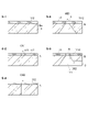
- the manufacturing method of the nozzle plate according to the first embodiment includes the first step (S-1) to the fifth step (S-5) shown in FIG. 8 and below.
- a surface mask layer 112 is uniformly formed on the first surface (ejection surface Ba) of a single crystal silicon substrate B whose surface crystal orientation is the ⁇ 100 ⁇ plane. to form.
- a material for forming the surface mask layer 112 is not particularly limited.
- a material for forming the surface mask layer 112 for example, an oxide such as SiO 2 (silicon oxide), metal plating such as Al (aluminum) or Cr (chromium), resin, or the like can be used.
- a thermal oxidation method or a CVD method is applied to form the surface mask layer 112 made of SiO 2 .
- a thermal oxidation method or a CVD method is applied to form the surface mask layer 112 made of SiO 2 .
- SiO 2 by thermal oxidation is preferred. This is because SiO 2 has good adhesion to Si and has the effect of preventing side etching during anisotropic wet etching, which will be described later.
- the surface mask layer 112 may have a single layer structure as shown in FIG. 8, or may have a multilayer structure.
- a resist pattern is formed on the surface mask layer 112 by a well-known photolithographic technique.
- a positive photoresist or a negative photoresist can be used to form the resist pattern.
- Known materials can be used as the positive photoresist and the negative photoresist.
- ZPN-1150-90 manufactured by Nippon Zeon Co., Ltd. can be used as a negative photoresist.
- OFPR-800LB and OEBR-CAP112PM manufactured by Tokyo Ohka Kogyo Co., Ltd. can be used as a positive photoresist.
- the resist layer is formed by applying it to a predetermined thickness using a spin coater or the like. After that, a pre-baking process is performed under conditions such as 110° C. for 90 seconds.
- HMDS hexamethyldisilazane
- the HMDS treatment is an organic material called hexamethyldisilazane, and for example, OAP (hexamethyldisilazane, manufactured by Tokyo Ohka Kogyo Co., Ltd.) can be used.
- OAP hexamethyldisilazane, manufactured by Tokyo Ohka Kogyo Co., Ltd.
- the coating may be performed using a spin coater, or exposure to hexamethyldisilazane vapor can be expected to improve adhesion.
- a predetermined mask is used to expose the resist layer with an aligner or the like.
- the amount of light is about 50 mJ/cm 2 .
- a developing solution for example, NMD-3 manufactured by Tokyo Ohka Kogyo Co., Ltd. for 60 to 90 seconds
- the opening pattern 113 is formed by dry etching (DE1) the surface mask layer 112 using the resist pattern as a mask. After forming the opening pattern 113, the resist pattern is removed.
- Dry etching is performed using a dry etching device such as a RIE (Reactive Ion Etching) device or an ICP (Inductively Coupled Plasma)-RIE etching device, which is a dry etching device that employs an inductive coupling method for the discharge method.
- a dry etching device such as a RIE (Reactive Ion Etching) device or an ICP (Inductively Coupled Plasma)-RIE etching device, which is a dry etching device that employs an inductive coupling method for the discharge method.
- RIE Reactive Ion Etching
- ICP Inductively Coupled Plasma
- CHF 3 trifluoromethane
- CF 4 tetrafluoromethane
- etching is performed for a predetermined time under conditions of a CHF 3 gas flow rate of 80 sccm, a pressure of 3 Pa, and an RF power of 90 W to obtain a slit pattern. can be formed.
- ⁇ Removal of resist pattern> As a method for removing the resist pattern, for example, a wet process using acetone or an acid solution or a dry process using oxygen plasma can be used.
- the substrate B under the opening pattern 113 is through-processed from the surface by dry etching (DE2) to form through-holes.
- the dry etching (DE2) can be performed using an ICP-RIE etching apparatus that employs an inductively coupled plasma discharge method.
- SF 6 sulfur hexafluoride
- C 4 F 8 cyclobutane octafluoride
- O 2 oxygen
- the nozzle taper portion 1112 is formed by enlarging the through hole by anisotropic wet etching (WE1).
- ⁇ Anisotropic wet etching> In the anisotropic wet etching (WE1) of the fourth step, an alkaline aqueous solution such as KOH (potassium hydroxide), TMAH (tetramethylammonium hydroxide), EDP (ethylenediamine pyrocatechol) is used. Since the substrate B is single-crystal silicon, the nozzle taper portion 1112 has a ⁇ 111 ⁇ plane with an extremely slow etching rate and a taper angle ⁇ of 35.3°.
- KOH potassium hydroxide
- TMAH tetramethylammonium hydroxide
- EDP ethylenediamine pyrocatechol
- a mask layer is formed at a predetermined location in the middle of the nozzle taper portion 1112 .
- a discharge channel pattern to be the discharge channel C is formed in the mask layer.
- the substrate B under the discharge channel pattern is dry-etched (DE2) to perform a deep excavation process, thereby forming the discharge channel C.
- the mask layer can be formed by spray coating or electrodeposition resist.
- the mask layer can be patterned with a discharge channel pattern by photolithography.
- the nozzle taper portion 1112 is formed by anisotropically wet etching the substrate B of single crystal silicon. Therefore, compared to the case where the nozzle taper portion 1112 is formed by the Bosch process, it is possible to manufacture the nozzle plate 110 with no scallops and small surface roughness. As a result, the nozzle plate 110 with excellent meniscus stability and high injection stability can be manufactured.
- the substrate B is made of single crystal silicon, it can be microfabricated on the order of ⁇ m by dry etching or photolithography.
- the taper angle ⁇ is stabilized at 35.3°, and variations in shape are less likely to occur among the plurality of nozzle flow paths 111 in one nozzle plate 110. Become.
- anisotropic wet etching (WE1)
- the etching progresses with the straight communicating portion 1113 remaining, and as time elapses, the straight communicating portion 1113 recedes in the left-right direction to form a nozzle taper.
- a portion 1112 is formed. Therefore, in the fourth step according to the second embodiment, the anisotropic wet etching (WE2) is time-controlled so as to stop earlier than the anisotropic wet etching (WE1) according to the first embodiment.
- a straight communication portion 1113 can be formed in the nozzle channel 111 .
- the through hole formed from one opening pattern 113 is enlarged for each nozzle flow path 111, and the nozzle tapered portion 1112 and the straight opening are formed.
- a communicating portion 1113 is formed. Therefore, it is possible to manufacture the nozzle plate 110 having the nozzle flow path 111 in which the nozzle tapered portion 1112 and the straight communication portion 1113 are continuous without positional deviation.
- Such a nozzle plate 110 maintains the symmetry of the ink flow and stabilizes the ejection angle. Furthermore, stagnation is less likely to occur in the nozzle flow path 111, and bubble removal is improved.
- a discharge channel pattern 114 is formed on the surface mask layer 112 of the bonding surface Bb.
- the discharge channel pattern 114 can be formed using the same material and method as the opening pattern 113 in the second step of the method for manufacturing the nozzle plate 110 according to the first embodiment.
- the substrate B under the discharge channel pattern 114 is deeply etched by dry etching (DE2) to form the discharge channel C.
- the discharge channel mask layer 115 is formed on the side and bottom surfaces of the discharge channel C, and the surface mask layer 112 formed on the bonding surface Bb is removed.
- the discharge channel mask layer 115 can be formed using the same material and method as the surface mask layer 112 . As a method for removing the surface mask layer 112, etching may be performed by an RIE apparatus or the like until the surface mask layer 112 is removed. At this time, the discharge channel mask layer 115 is more difficult to remove than the surface mask layer 112 because it is located on the side walls and bottom surface.
- the second step (FIG. 10 S-2) to the fourth step (FIG. 10 S-4) are performed in the same manner as in the first embodiment.
- the surface mask layer 112 on the ejection surface Ba side is dry-etched (DE1) to form an opening pattern 113 .
- the substrate B under the opening pattern 113 is dry-etched (DE2) to form a through-hole.
- anisotropic wet etching (WE1) is performed to enlarge the through hole and form a nozzle taper portion 1112 .
- the discharge channel C formed in the seventh step (FIG. 10 S-7) remains without being etched. It will be done.
- the formation of the discharge channel pattern 114 and the dry etching (DE2) are performed on the bonding surface Bb of the substrate B, which is a plane.
- a discharge channel C can be formed. Therefore, compared to the case where a mask layer is formed on the nozzle taper portion 1112 and dry etching (DE2) is performed, processing becomes easier, and the nozzle plate 110 can be manufactured with high dimensional accuracy. In addition, it becomes easier to maintain the parallelism between the discharge channel C and the ejection surface Ba.
- the fourth step (FIG. 10 S-4) of the method for manufacturing the nozzle plate 110 according to the third embodiment also includes the fourth step (FIG. 10) according to the second embodiment.
- anisotropic wet etching (WE2) may be performed with time control to form a straight communication portion 1113 in the nozzle flow path 111 .
- the opening pattern 113 A nozzle straight portion 1111 may be formed by deep etching the lower substrate B halfway through dry etching (DE2), and a mask layer may be provided on the side surface of the nozzle straight portion 1111 .
- the nozzle straight portion 1111 remains without being etched during the anisotropic wet etching (WE1 or WE2) in the fourth step (FIG. 11 S-4).
- WE1 or WE2 anisotropic wet etching
- a configured nozzle straight portion 1111 may be provided.
- a protective film may be formed on the nozzle plate 110 for long-term use in ink ejection.
- a step of forming a protective film covering the surface including the inside of the nozzle channel 111 is performed.
- the protective film a material that does not dissolve upon contact with ink may be used.
- metal oxide films tantalum pentoxide, hafnium oxide, niobium oxide, titanium oxide, zirconium oxide, etc.
- metal silicate films containing silicon in metal oxide films tantalum silicate, hafnium silicate, niobium silicate, titanium silicate, zirconium silicate, etc.
- an organic film such as polyimide, polyamide, or parylene may be used as the protective film.
- the thickness of the protective film is not particularly limited, but can be, for example, 0.05 ⁇ m to 20 ⁇ m.
- a nozzle plate 110 having a thickness of 300 ⁇ m and having 1000 nozzle flow paths 111 satisfying the conditions of the following examples and comparative examples is joined to another plate or the like to form an inkjet head 10 , and the inkjet head 10 is used for inkjet recording. It was mounted on the device 1.
- Example 1 A conical nozzle taper portion 1112 having a taper angle ⁇ of 45° was formed on the substrate B made of SUS using a laser. Then, the discharge channel C is formed in the middle of the nozzle taper portion 1112 when viewed from the side of the ejection surface Ba such that the taper height h is 100 ⁇ m.
- the nozzle opening N was formed to have a circular diameter of 40 ⁇ m.
- Example 2 A nozzle straight portion 1111 having a height of 10 ⁇ m and a diameter of 40 ⁇ m was formed so as to be continuous with the end portion of the nozzle tapered portion 1112 on the ejection surface Ba side. Other conditions are the same as in Example 1.
- Example 3 A discharge channel C is formed in the middle of the nozzle taper portion 1112 when viewed from the side of the ejection surface Ba such that the taper height h is 4 ⁇ m. Other conditions are the same as in Example 1. (Example 4) A discharge flow path C is formed in the middle of the nozzle taper portion 1112 when viewed from the side of the ejection surface Ba such that the taper height h is 5 ⁇ m. Other conditions are the same as in Example 1. (Example 5) A discharge flow path C is formed in the middle of the nozzle taper portion 1112 when viewed from the side of the ejection surface Ba such that the taper height h is 19 ⁇ m. Other conditions are the same as in Example 1.
- Example 6 A discharge channel C is formed in the middle of the nozzle taper portion 1112 when viewed from the side of the ejection surface Ba such that the taper height h is 20 ⁇ m. Other conditions are the same as in Example 1. (Example 7) A discharge channel C is formed in the middle of the nozzle taper portion 1112 when viewed from the side of the ejection surface Ba such that the taper height h is 100 ⁇ m. Other conditions are the same as in Example 1. (Example 8) The discharge channel C was formed in the middle of the nozzle taper portion 1112 when viewed from the side of the ejection surface Ba such that the taper height h was 101 ⁇ m. Other conditions are the same as in Example 1.
- Example 9 A discharge channel C is formed in the middle of the nozzle taper portion 1112 when viewed from the side of the ejection surface Ba such that the taper height h is 200 ⁇ m. Other conditions are the same as in Example 1. (Example 10) The discharge channel C was formed in the middle of the nozzle taper portion 1112 when viewed from the side of the ejection surface Ba such that the taper height h was 201 ⁇ m. Other conditions are the same as in Example 1. (Example 11) The nozzle taper portion 1112 was formed so that the taper angle ⁇ was 76°. Other conditions are the same as in Example 1. (Example 12) The nozzle taper portion 1112 was formed so that the taper angle ⁇ was 75°.
- Example 13 The nozzle taper portion 1112 was formed so that the taper angle ⁇ was 61°. Other conditions are the same as in Example 1.
- Example 14 The nozzle taper portion 1112 was formed so that the taper angle ⁇ was 60°. Other conditions are the same as in Example 1.
- Example 15 The nozzle taper portion 1112 was formed so that the taper angle ⁇ was 30°. Other conditions are the same as in Example 1.
- Example 16 The nozzle taper portion 1112 was formed so that the taper angle ⁇ was 29°. Other conditions are the same as in Example 1.
- Example 17 The nozzle taper portion 1112 was formed so that the taper angle ⁇ was 15°. Other conditions are the same as in Example 1.
- Example 18 The nozzle taper portion 1112 was formed so that the taper angle ⁇ was 14°. Other conditions are the same as in Example 1.
- Example 19 Anisotropic wet etching is performed on the substrate B, which is single crystal silicon, to form a quadrangular pyramid-shaped nozzle taper portion 1112 having a taper angle ⁇ of 35.3° and formed of four ⁇ 111 ⁇ planes and four ⁇ 100 ⁇ plane is formed. Then, the discharge channel C is formed in the middle of the nozzle taper portion 1112 when viewed from the side of the ejection surface Ba such that the taper height h is 100 ⁇ m.
- the nozzle opening portion N was formed to have a square shape of 40 ⁇ m on each side.
- Two such nozzle plates 110 were prepared in which the discharge passages C were formed so as to be positioned at the boundaries of the adjacent nozzle taper portions 1112 .
- the nozzle taper portion 1112 is formed in the nozzle flow channel 111, but the discharge flow channel C is formed in the middle of the nozzle taper portion 1112 when viewed from the side of the ejection surface Ba. It is formed in the boundary part.
- test 1-2 was performed using the inkjet recording apparatus 1 equipped with the inkjet head 10 having the nozzle plate 110 of Examples 1-19 and Comparative Examples 1-2.
- Test 1 Upper limit speed test of meniscus stability
- the inkjet head 10 is filled with water-based ink having a viscosity of about 5 cP at normal temperature, and the ejection speed is increased from 5 m/s so that the driving frequency is 40 kHz and the ink droplet volume ejected from the nozzle opening N is 10 pL. while ejecting. Then, out of the 100 nozzle openings N, the injection speed at which the meniscus becomes unstable and injection defects occur in five or more nozzle openings N is measured.
- the evaluation is as follows: " ⁇ " when the injection speed is 12 m/s or more; “ ⁇ ” when the injection speed is less than 12 m/s and 11 m/s or more; was rated as “ ⁇ ”, less than 10 m/s and 9 m/s or more as “ ⁇ ”, and less than 9 m/s as 7 m/s or more as “x”.
- Test 1-2 The results of Test 1-2 are shown in Table I.
- Example 19 when the discharge channel C was formed so as to be located at the corner where the two ⁇ 100 ⁇ planes of the straight communication portion 1113 intersect, the result was "O", but the bubbles that floated up were good. had been expelled. Also, in Example 19, when the discharge flow path C was formed so as to be located at the boundary between the adjacent nozzle taper portions 1112, the result was " ⁇ ".
- Example 1 when comparing Example 1 and Example 2, it can be seen that providing the nozzle straight portion 1111 in the nozzle flow path 111 can further improve the meniscus stability and increase the upper limit injection speed. This is because the resistance applied when ink is ejected from the nozzle openings N increases, and the vibration of the meniscus is suppressed.
- the preferable taper height h is 5 ⁇ m to 200 ⁇ m, and the more preferable taper height h is 20 ⁇ m to 100 ⁇ m. It can be seen that the upper limit injection speed can be further increased by setting the taper height h within such a range.
- the preferable taper angle ⁇ is 15° or more and 75° or less, and the more preferable taper angle ⁇ is 30° or more and 60° or less. It can be seen that the upper limit injection speed can be further increased by setting the taper angle ⁇ within such a range. In addition, it can be seen that it becomes easier to circulate air bubbles together with the sedimented ink pigment, and nozzle clogging is less likely to occur.
- the substrate B may be single crystal silicon or SUS.
- the cross-sectional shape of the nozzle taper portion 1112 and the shape of the nozzle opening portion N are not particularly limited.
- Test 3 A meniscus stability upper limit speed test shown in Test 1 was conducted while changing the driving frequency of the ink jet recording apparatus 1 from 10 kHz to 100 kHz. In addition, the evaluation criteria are the same as in Test 1.
- Test 4 Suitable droplet volume test
- Test 1 A meniscus stability upper limit speed test shown in Test 1 was conducted while changing the amount of droplets ejected from the nozzle opening N from 10 pL to 300 pL.
- the evaluation criteria are the same as in Test 1.
- Tests 3 and 4 are shown in Tables II and III, respectively.
- the inkjet recording apparatus 1 mounted with the inkjet head 10 having the conventional nozzle plate 110 could not effectively eject droplets unless the driving frequency was set to 20 kHz or less. .
- the inkjet recording apparatus 1 equipped with the inkjet head 10 having the nozzle plate 110 according to the present embodiment can effectively eject liquid droplets even if the driving frequency is increased to at least 100 kHz.
- the ink jet recording apparatus 1 equipped with the ink jet head 10 having the conventional nozzle plate 110 is set so that the amount of liquid droplets ejected from the nozzle openings N is 20 pL or less. Without it, effective droplet ejection could not be performed. However, the inkjet recording apparatus 1 equipped with the inkjet head 10 having the nozzle plate 110 according to the present embodiment can effectively eject droplets even if the droplet volume ejected from the nozzle openings N is increased to 300 pL. I understand.
- the present invention can be used for a nozzle plate, a droplet ejection head, a droplet ejection device, and a method for manufacturing a nozzle plate, in which ejection is stable under a wider range of conditions regarding the droplet amount and ejection speed.
- droplet ejection device (inkjet recording device) 10 droplet ejection head (inkjet head) 110 Nozzle plate 111 Nozzle channel 1111 Nozzle straight part 1112 Nozzle taper part 1113 Straight communication part 112 Surface mask layer 113 Opening pattern 114 Discharge channel pattern 115 Discharge channel mask layer B Substrate Ba First surface (ejection surface) Bb second surface (adhesion surface) C discharge channel N nozzle opening L axis parallel to nozzle central axis ⁇ taper angles DE1, DE2 dry etching WE1, WE2 anisotropic wet etching
Landscapes
- Engineering & Computer Science (AREA)
- Manufacturing & Machinery (AREA)
- Particle Formation And Scattering Control In Inkjet Printers (AREA)
Priority Applications (2)
| Application Number | Priority Date | Filing Date | Title |
|---|---|---|---|
| CN202280043203.1A CN117529407A (zh) | 2021-06-22 | 2022-05-30 | 喷嘴板、液滴吐出头、液滴吐出装置以及喷嘴板的制造方法 |
| JP2023529752A JP7848799B2 (ja) | 2021-06-22 | 2022-05-30 | ノズルプレート、液滴吐出ヘッド、液滴吐出装置及びノズルプレートの製造方法 |
Applications Claiming Priority (2)
| Application Number | Priority Date | Filing Date | Title |
|---|---|---|---|
| JP2021103021 | 2021-06-22 | ||
| JP2021-103021 | 2021-06-22 |
Publications (1)
| Publication Number | Publication Date |
|---|---|
| WO2022270237A1 true WO2022270237A1 (ja) | 2022-12-29 |
Family
ID=84545606
Family Applications (1)
| Application Number | Title | Priority Date | Filing Date |
|---|---|---|---|
| PCT/JP2022/021937 Ceased WO2022270237A1 (ja) | 2021-06-22 | 2022-05-30 | ノズルプレート、液滴吐出ヘッド、液滴吐出装置及びノズルプレートの製造方法 |
Country Status (3)
| Country | Link |
|---|---|
| JP (1) | JP7848799B2 (https=) |
| CN (1) | CN117529407A (https=) |
| WO (1) | WO2022270237A1 (https=) |
Citations (3)
| Publication number | Priority date | Publication date | Assignee | Title |
|---|---|---|---|---|
| US20080129780A1 (en) * | 2006-12-01 | 2008-06-05 | Samsung Electronics Co., Ltd | Nozzle plate of inkjet printhead and method of manufacturing the nozzle plate |
| JP2010023361A (ja) * | 2008-07-22 | 2010-02-04 | Konica Minolta Holdings Inc | インクジェット記録方法 |
| WO2018061543A1 (ja) * | 2016-09-28 | 2018-04-05 | コニカミノルタ株式会社 | インクジェットヘッドおよびその製造方法と、インクジェットプリンタ |
Family Cites Families (6)
| Publication number | Priority date | Publication date | Assignee | Title |
|---|---|---|---|---|
| JP4936880B2 (ja) * | 2006-12-26 | 2012-05-23 | 株式会社東芝 | ノズルプレート、ノズルプレートの製造方法、液滴吐出ヘッド及び液滴吐出装置 |
| KR101968636B1 (ko) | 2012-12-06 | 2019-04-12 | 삼성전자주식회사 | 잉크젯 프린팅 장치 및 노즐 형성 방법 |
| JP6216626B2 (ja) * | 2013-11-22 | 2017-10-18 | 株式会社東芝 | インクジェットヘッド |
| JP2017100413A (ja) | 2015-12-04 | 2017-06-08 | 株式会社リコー | 吐出駆動装置、液体吐出ヘッド、液体吐出ユニット、液体を吐出する装置 |
| JP7243053B2 (ja) * | 2018-06-26 | 2023-03-22 | セイコーエプソン株式会社 | 液体吐出装置および液体吐出方法 |
| JP7119943B2 (ja) * | 2018-11-26 | 2022-08-17 | コニカミノルタ株式会社 | ノズルプレートの製造方法及びインクジェットヘッドの製造方法 |
-
2022
- 2022-05-30 JP JP2023529752A patent/JP7848799B2/ja active Active
- 2022-05-30 WO PCT/JP2022/021937 patent/WO2022270237A1/ja not_active Ceased
- 2022-05-30 CN CN202280043203.1A patent/CN117529407A/zh active Pending
Patent Citations (3)
| Publication number | Priority date | Publication date | Assignee | Title |
|---|---|---|---|---|
| US20080129780A1 (en) * | 2006-12-01 | 2008-06-05 | Samsung Electronics Co., Ltd | Nozzle plate of inkjet printhead and method of manufacturing the nozzle plate |
| JP2010023361A (ja) * | 2008-07-22 | 2010-02-04 | Konica Minolta Holdings Inc | インクジェット記録方法 |
| WO2018061543A1 (ja) * | 2016-09-28 | 2018-04-05 | コニカミノルタ株式会社 | インクジェットヘッドおよびその製造方法と、インクジェットプリンタ |
Also Published As
| Publication number | Publication date |
|---|---|
| CN117529407A (zh) | 2024-02-06 |
| JP7848799B2 (ja) | 2026-04-21 |
| JPWO2022270237A1 (https=) | 2022-12-29 |
Similar Documents
| Publication | Publication Date | Title |
|---|---|---|
| KR101087437B1 (ko) | 액체 토출 헤드 | |
| US8551692B1 (en) | Forming a funnel-shaped nozzle | |
| CN101327682A (zh) | 喷嘴基板、液滴喷头及其制造方法、以及液滴喷出装置 | |
| CN101035682A (zh) | 打印头喷嘴形成 | |
| US12409655B2 (en) | Reducing size variations in funnel nozzles | |
| JP7119943B2 (ja) | ノズルプレートの製造方法及びインクジェットヘッドの製造方法 | |
| WO2023008375A1 (ja) | ノズルプレート、液滴吐出ヘッド、液滴吐出装置及びノズルプレートの製造方法 | |
| JP2017209939A (ja) | 記録素子基板、液体吐出ヘッドおよび液体吐出装置 | |
| US9919528B2 (en) | Liquid ejecting head, liquid ejecting apparatus, and liquid ejecting head manufacturing method | |
| JP5107891B2 (ja) | 液滴射出デバイス | |
| WO2022270237A1 (ja) | ノズルプレート、液滴吐出ヘッド、液滴吐出装置及びノズルプレートの製造方法 | |
| WO2016158917A1 (ja) | 液体吐出ヘッド用ノズルプレートの製造方法、液体吐出ヘッド用ノズルプレート及び液体吐出ヘッド | |
| JP7790551B2 (ja) | ノズルプレート、液滴吐出ヘッド、液滴吐出装置及びノズルプレートの製造方法 | |
| KR100519760B1 (ko) | 압전 방식 잉크젯 프린트헤드의 제조방법 | |
| US11123984B2 (en) | Liquid ejecting head, method for manufacturing liquid ejecting head, and liquid ejecting system | |
| JP7683681B2 (ja) | ノズルプレートの製造方法 | |
| CN119923321A (zh) | 喷嘴板的制造方法 | |
| JP5862116B2 (ja) | 液体吐出装置の流路板の製造方法 | |
| JP2008110560A (ja) | 液体吐出ヘッド用ノズルプレート及び液体吐出ヘッド用ノズルプレートの製造方法 | |
| JP2005138589A (ja) | 流体イジェクタ装置を形成する方法及び流体イジェクタ | |
| JP2008221110A (ja) | 液体吐出ヘッド |
Legal Events
| Date | Code | Title | Description |
|---|---|---|---|
| 121 | Ep: the epo has been informed by wipo that ep was designated in this application |
Ref document number: 22828156 Country of ref document: EP Kind code of ref document: A1 |
|
| WWE | Wipo information: entry into national phase |
Ref document number: 2023529752 Country of ref document: JP |
|
| WWE | Wipo information: entry into national phase |
Ref document number: 202280043203.1 Country of ref document: CN |
|
| NENP | Non-entry into the national phase |
Ref country code: DE |
|
| 122 | Ep: pct application non-entry in european phase |
Ref document number: 22828156 Country of ref document: EP Kind code of ref document: A1 |