WO2022269778A1 - 端末及び無線通信方法 - Google Patents
端末及び無線通信方法 Download PDFInfo
- Publication number
- WO2022269778A1 WO2022269778A1 PCT/JP2021/023688 JP2021023688W WO2022269778A1 WO 2022269778 A1 WO2022269778 A1 WO 2022269778A1 JP 2021023688 W JP2021023688 W JP 2021023688W WO 2022269778 A1 WO2022269778 A1 WO 2022269778A1
- Authority
- WO
- WIPO (PCT)
- Prior art keywords
- transmission
- reception point
- point
- counter
- reception
- Prior art date
- Legal status (The legal status is an assumption and is not a legal conclusion. Google has not performed a legal analysis and makes no representation as to the accuracy of the status listed.)
- Ceased
Links
Images


Classifications
-
- H—ELECTRICITY
- H04—ELECTRIC COMMUNICATION TECHNIQUE
- H04W—WIRELESS COMMUNICATION NETWORKS
- H04W76/00—Connection management
- H04W76/10—Connection setup
- H04W76/19—Connection re-establishment
-
- H—ELECTRICITY
- H04—ELECTRIC COMMUNICATION TECHNIQUE
- H04B—TRANSMISSION
- H04B7/00—Radio transmission systems, i.e. using radiation field
- H04B7/02—Diversity systems; Multi-antenna system, i.e. transmission or reception using multiple antennas
- H04B7/022—Site diversity; Macro-diversity
-
- H—ELECTRICITY
- H04—ELECTRIC COMMUNICATION TECHNIQUE
- H04B—TRANSMISSION
- H04B7/00—Radio transmission systems, i.e. using radiation field
- H04B7/02—Diversity systems; Multi-antenna system, i.e. transmission or reception using multiple antennas
- H04B7/04—Diversity systems; Multi-antenna system, i.e. transmission or reception using multiple antennas using two or more spaced independent antennas
- H04B7/06—Diversity systems; Multi-antenna system, i.e. transmission or reception using multiple antennas using two or more spaced independent antennas at the transmitting station
- H04B7/0686—Hybrid systems, i.e. switching and simultaneous transmission
- H04B7/0695—Hybrid systems, i.e. switching and simultaneous transmission using beam selection
- H04B7/06952—Selecting one or more beams from a plurality of beams, e.g. beam training, management or sweeping
- H04B7/06964—Re-selection of one or more beams after beam failure
-
- H—ELECTRICITY
- H04—ELECTRIC COMMUNICATION TECHNIQUE
- H04W—WIRELESS COMMUNICATION NETWORKS
- H04W16/00—Network planning, e.g. coverage or traffic planning tools; Network deployment, e.g. resource partitioning or cells structures
- H04W16/24—Cell structures
- H04W16/28—Cell structures using beam steering
-
- H—ELECTRICITY
- H04—ELECTRIC COMMUNICATION TECHNIQUE
- H04W—WIRELESS COMMUNICATION NETWORKS
- H04W76/00—Connection management
- H04W76/10—Connection setup
- H04W76/15—Setup of multiple wireless link connections
-
- H—ELECTRICITY
- H04—ELECTRIC COMMUNICATION TECHNIQUE
- H04B—TRANSMISSION
- H04B7/00—Radio transmission systems, i.e. using radiation field
- H04B7/02—Diversity systems; Multi-antenna system, i.e. transmission or reception using multiple antennas
- H04B7/04—Diversity systems; Multi-antenna system, i.e. transmission or reception using multiple antennas using two or more spaced independent antennas
- H04B7/0404—Diversity systems; Multi-antenna system, i.e. transmission or reception using multiple antennas using two or more spaced independent antennas the mobile station comprising multiple antennas, e.g. to provide uplink diversity
Definitions
- the present disclosure relates to a terminal and wireless communication method compatible with multiple transmission/reception points.
- the 3rd Generation Partnership Project (3GPP) has specified the 5th generation mobile communication system (also called 5G, New Radio (NR) or Next Generation (NG)), and the next generation specification called Beyond 5G, 5G Evolution or 6G We are also proceeding with 5G, 5G Evolution or 6G We are also proceeding with 5G, 5G Evolution or 6G We are also proceeding with 5G, 5G Evolution or 6G We are also proceeding with 5G, 5G Evolution or 6G We are also proceeding with 5G, 5G Evolution or 6G
- Non-Patent Document 1 the extension of Multiple-Input Multiple-Output (MIMO) is being considered (Non-Patent Document 1).
- a terminal User Equipment, UE
- TRPs transmission/reception points
- Non-Patent Document 2 BeamFailureDetectionTimer
- the following disclosure is made in view of this situation, and provides a terminal and wireless communication method that can appropriately detect and recover from beam failures when supporting multiple TRPs (mTRPs). for the purpose of providing
- One aspect of the present disclosure is a transmission/reception unit (wireless communication unit 210) that transmits and receives beams to and from a first transmission/reception point and a second transmission/reception point, and control that controls the beams of the first transmission/reception point and the second transmission/reception point.
- a control unit 240 wherein the control unit detects a beam failure of the beam with the first transmission/reception point in a state where the first transmission/reception point and the second transmission/reception point are set.
- a terminal using the counter and timer for the first transmission/reception point, in a state in which the first transmission/reception point and the second transmission/reception point are set, when a beam failure of the beam with the second transmission/reception point is detected, A terminal (UE 200) using the counter and timer for the second transmission/reception point.
- One aspect of the present disclosure includes transmitting and receiving a beam to and from a first transmission and reception point and a second transmission and reception point, and controlling the beam to and from the first transmission and reception point and the second transmission and reception point, wherein the controlling In the step, in a state in which the first transmission/reception point and the second transmission/reception point are set, if a beam failure of the beam with the first transmission/reception point is detected, the counter and timer for the first transmission/reception point are set. and using a counter and timer for the second transmission/reception point when a beam failure of the beam with the second transmission/reception point is detected in a state where the first transmission/reception point and the second transmission/reception point are set.
- a wireless communication method in a state in which the first transmission/reception point and the second transmission/reception point are set, if a beam failure of the beam with the first transmission/reception point is detected, the counter and timer for the first transmission/reception point are set.
- FIG. 1 is an overall schematic configuration diagram of a radio communication system 10.
- FIG. 2 is a functional block configuration diagram of the gNB100.
- FIG. 3 is a functional block configuration diagram of UE200.
- FIG. 4 is a diagram showing an example of beam BM setting in the mTRP environment.
- FIG. 5 is a diagram showing an example of an operation flow regarding BFD and BFR of the UE 200 according to Operation Example 1.
- FIG. 6 is a diagram illustrating an example of a beam failure-related RRC communication sequence according to Operation Example 2 and Operation Example 3.
- FIG. FIG. 7 is a diagram illustrating a configuration example of the RLF report according to Operation Example 2. As illustrated in FIG. FIG. FIG.
- FIG. 8 is a diagram showing a configuration example of MCGFailureInfo (FailureReportMCG) according to Operation Example 2.
- FIG. 9 is a diagram showing a configuration example of SCGFailureInfo (FailureReportSCG) according to Operation Example 2.
- FIG. 10 is a diagram showing a configuration example of beamFailureRecoverySCellConfig according to Operation Example 3.
- FIG. 11 is a diagram showing an example of the hardware configuration of gNB100 and UE200.
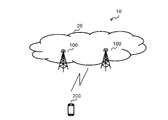
- FIG. 1 is an overall schematic configuration diagram of a radio communication system 10 according to the present embodiment.
- the radio communication system 10 is a radio communication system according to 5G New Radio (NR), and includes a Next Generation-Radio Access Network 20 (hereinafter NG-RAN 20 and terminals 200 (User Equipment 200, hereinafter UE 200).
- NG-RAN 20 Next Generation-Radio Access Network 20
- UE 200 User Equipment 200
- the wireless communication system 10 may be a wireless communication system according to a system called Beyond 5G, 5G Evolution, or 6G.
- NG-RAN 20 includes a radio base station 100 (hereinafter gNB 100).
- gNB 100 radio base station 100
- the specific configuration of the radio communication system 10 including the number of gNBs and UEs is not limited to the example shown in FIG.
- NG-RAN 20 actually includes multiple NG-RAN Nodes, specifically gNBs (or ng-eNBs), and is connected to a 5G-compliant core network (5GC, not shown). Note that NG-RAN 20 and 5GC may simply be referred to as a "network”.
- gNBs or ng-eNBs
- 5GC 5G-compliant core network
- the gNB100 is an NR-compliant radio base station and performs NR-compliant radio communication with the UE200.
- the gNB 100 and the UE 200 control radio signals transmitted from a plurality of antenna elements, specifically a plurality of transmission/reception points, for example, transmission/reception point 101 and transmission/reception point 102 (not shown in FIG. 1, see FIG. 4).
- Massive MIMO that generates a beam BM with higher directivity (see Fig. 4), carrier aggregation (CA) that uses multiple component carriers (CC) in a bundle, and between UE and multiple NG-RAN nodes It can support dual connectivity (DC) that communicates at the same time.
- DC dual connectivity
- the gNB 100 may transmit and receive radio signals via one or more transmission and reception points (TRP: Transmission and Reception Points).
- TRP Transmission and Reception Points
- the gNB 100 can support single-user MIMO using one TRP, and coordinate two TRPs to support distributed MIMO transmission of a predetermined channel (eg, PDSCH: Physical Downlink Shared Channel).
- PDSCH Physical Downlink Shared Channel
- TRP may be read interchangeably as cell, radio base station, Node B, antenna port, antenna port group, antenna panel, panel, antenna element, transmission/reception point, etc.
- the UE 200 may support operations related to multiple transmission/reception points (mTRPs) between cells by signaling such as Layer 1 and/or Layer 2.
- mTRPs multiple transmission/reception points
- the UE 200 can support beam BM failure detection (BFD) and recovery (BFR) in an mTRP environment.
- BFD beam BM failure detection
- BFR recovery
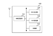
- FIG. 2 is a functional block configuration diagram of gNB100.
- FIG. 3 is a functional block configuration diagram of UE200. Note that FIGS. 2 and 3 only show main functional blocks related to the description of the embodiments, and that the gNB 100 and UE 200 have other functional blocks (eg, power supply units, etc.). . 2 and 3 show the functional block configurations of the gNB 100 and UE 200, and please refer to FIG. 11 for the hardware configuration.
- gNB 100 includes radio communication section 110 , RRC processing section 120 , TRP setting section 130 and control section 140 .
- the radio communication unit 110 transmits downlink signals (DL signals) according to NR.
- Radio communication section 110 also receives an uplink signal (UL signal) according to NR.
- the RRC processing unit 120 executes various processes in the radio resource control layer (RRC). Specifically, RRC processing section 120 can transmit RRC Reconfiguration to UE 200 . Also, RRC processing section 120 can receive RRC Reconfiguration Complete, which is a response to RRC Reconfiguration, from UE 200 . Note that RRC processing section 120 may perform processing related to not only these RRC layer messages but also other messages (for example, RRC Release and system information (SIB: System Information Block, etc.).
- SIB System Information Block
- the TRP setting unit 130 executes settings related to TRP.
- gNB 100 may comprise multiple TRPs.
- the TRP setting unit 130 can set the plurality of TRPs (mTRPs).
- the TRP setting section 130 may perform settings related to MIMO and beamforming.
- MIMO single-user MIMO may be supported as described above, and multi-user MIMO may also be supported.
- the TRP setting unit 130 can set the formation of a plurality of beam BMs with different transmission directions using the TRP, and beam BM reception from the UE 200 using the TRP.
- the TRP setting unit 130 can perform processing related to beam BM failure detection (BFD) and recovery (BFR).
- the control unit 140 controls each functional block that configures the gNB100.
- the control unit 140 can perform control regarding the beam BM in the mTRP environment.
- control unit 140 can perform control related to beam measurement by the UE 200, beam reporting from the UE 200, and beam instruction from the gNB 100.
- BFR Beam Failure Recovery
- PCell primary cell
- PSCell Primary SCell
- Sending a beam failure recovery request to the gNB 100 with a non-existing beam BM may be interpreted as a procedure for early recovery of the failed beam BM.
- Control unit 140 based on the beam report reported from UE 200, specifically, the received power (RSRP: Reference Signal Received Power) measured by UE 200, performs beam control considering interference between cells or TRPs You can
- control unit 140 uses TRP/BFD-RS (Reference Signal) or a beam failure counter (BFI_COUNTER) and a timer (beamFailureDetectionTimer) unique to each TRP using TRP/BFD-RS (Reference Signal) or BFR-RS for BFD and BFR in the mTRP environment. ) may be introduced.
- TRP/BFD-RS and BFR-RS are tentative names, are reference signals related to TRP and/or BFD/BFR, and may be interpreted as a type of DL-RS (Downlink Reference Signal).
- UE 200 includes radio communication section 210 , RRC processing section 220 , beam setting section 230 and control section 240 .
- the radio communication unit 210 transmits an uplink signal (UL signal) according to NR. Also, the radio communication unit 210 receives an uplink signal (DL signal) according to NR.
- UL signal uplink signal
- DL signal uplink signal
- the radio communication unit 210 receives multiple beams BM transmitted from the gNB 100. Also, the radio communication unit 210 transmits a beam BM in a specific direction toward the gNB 100, that is, a beam BM with directivity. As described above, beam BM may be transmitted and received between UE 200 and gNB 100 (radio base station), in other words, transmit/receive point (TRP).
- TRP transmit/receive point
- the wireless communication unit 210 can transmit and receive multiple TRPs and beam BMs at different installation locations.
- the wireless communication unit 210 may constitute a transmitting/receiving unit that transmits/receives the beam BM to/from a first transmitting/receiving point (eg, transmitting/receiving point 101 (see FIG. 4)) and a second transmitting/receiving point (eg, transmitting/receiving point 102).
- the RRC processing unit 220 executes various processes in the radio resource control layer (RRC). Specifically, the RRC processing unit 220 can transmit and receive radio resource control layer messages.
- RRC radio resource control layer
- the RRC processing unit 220 can receive RRC Reconfiguration from the network, specifically from the NG-RAN 20. Also, the RRC processing unit 220 can transmit RRC Reconfiguration Complete, which is a response to RRC Reconfiguration, to the network.
- Such RRC messages may contain information on beam BM failure detection (BFD) and recovery (BFR).
- BFD beam BM failure detection
- BFR recovery
- the set values of the beam failure counter (BFI_COUNTER) and timer (beamFailureDetectionTimer) unique to each TRP described above may be included.
- the message may include a radio link failure (RLF) report and a cell group (master cell group (MCG), secondary cell group (SCG)) failure report (MCGFailureInfo/SCGFailureInfo).
- the failure report may include beam failure information elements (eg beamFailureRecoveryFailure, beamFailureRecoveryFailureForMultiTRP).
- the RRC processing unit 220 may receive system information broadcast from the gNB 100, specifically, Master Information Block (MIB) and System Information Block (SIB).
- the system information includes serving cell configuration (ServingCellConfig), and the configuration may include information elements (eg, candidateBeamRS) regarding mTRP and beam BM.
- the beam setting unit 230 performs setting regarding the beam BM transmitted and received by the wireless communication unit 210. Specifically, under the control of the control unit 240, the beam setting unit 230 can perform setting regarding transmission of the beam BM toward a specific TRP and reception of the beam BM from the specific TRP. As described above, the number of TRPs to be transmitted/received may be one, two, or more.
- the beam setting unit 230 may transmit a report on the beam BM to the network.
- the beam setting unit 230 can transmit a report (beamFailureRecoveryFailureForMultiTRP) indicating beam failure recovery failure for multiple TRPs to the network.
- the beam setting unit 230 may constitute a transmission/reception unit that transmits a report indicating failure to recover from a beam failure to a plurality of transmission/reception points.
- the beam setting unit 230 may receive a setting (candidateBeamRS) indicating a candidate beam for each of a plurality of TRPs from the network.
- the beam setting unit 230 may constitute a transmission/reception unit that receives settings indicating candidate beams for each of a plurality of transmission/reception points.
- a beam failure may be determined by measuring reception quality in the serving cell and non-serving cells that include the beam BM.
- the reception quality includes RSRP (Reference Signal Received Power), RSRQ (Reference Signal Received Quality), RSSI (Received Signal Strength Indicator), SINR (Signal-to-Interference plus Noise power Ratio) and the like.
- the reception quality may be CSI (Channel State Information).
- the serving cell may simply be interpreted as the cell to which the UE 200 is connected, but more precisely, in the case of an RRC_CONNECTED UE in which carrier aggregation (CA) is not set, the number of serving cells that constitute the primary cell is 1. Only one.
- the serving cell may be taken to refer to the set of one or more cells including the primary cell and all secondary cells.
- the control unit 240 controls each functional block that configures the UE200.
- the control unit 240 can perform control regarding the beam BM in the mTRP environment.
- the control unit 240 controls a plurality of TRPs, specifically beams with a first transmission/reception point (eg, transmission/reception point 101 (see FIG. 4)) and a second transmission/reception point (eg, transmission/reception point 102).
- a first transmission/reception point eg, transmission/reception point 101 (see FIG. 4)
- a second transmission/reception point eg, transmission/reception point 102
- Beam BM control may include beam BM directivity, transmission power, transmission timing, BFD threshold setting, BFR execution, and the like.
- control unit 240 detects a beam failure of the beam BM with the first transmission/reception point in a state in which the first transmission/reception point and the second transmission/reception point are set, that is, in a state in which multiple TRPs are set, , counters and timers for the first transmit/receive point (BFI_COUNTER_TRP1, beamFailureDetectionTimer_TRP1).
- control unit 240 may increment (increase) BFI_COUNTER_TRP1 and activate (start) beamFailureDetectionTimer_TRP1.
- control unit 240 uses the counter and timer (BFI_COUNTER_TRP2, beamFailureDetectionTimer_TRP2) for the second transmission/reception point when detecting beam failure of the beam BM with the second transmission/reception point. you can
- control unit 240 may increment (increase) BFI_COUNTER_TRP2 and activate (start) beamFailureDetectionTimer_TRP2.
- control unit 240 may execute an initial access procedure when the value of any counter (BFI_COUNTER_TRP1 or BFI_COUNTER_TRP2) exceeds a threshold in a specific cell.
- control unit 240 may execute a random access (RA) procedure when the threshold is exceeded.
- RA random access
- Execution of the RA procedure may be interpreted as sending Message 1 (PRACH: Physical Random Access Channel) and/or Message 3.
- PRACH Physical Random Access Channel
- performing the initial access procedure may be interpreted as performing beam failure recovery (BFR) including PRACH transmission.
- BFR beam failure recovery
- the specific cell may mean Special Cell (SpCell), and SpCell may mean PCell and PSCell.
- the control unit 240 performs beam failure recovery (BFR ) may be executed. Specifically, the control unit 240 may perform BFR including transmission of BFR MAC-CE (Control Element).
- FIG. 4 shows an example of beam BM setting in the mTRP environment.
- the UE 200 may transmit and receive multiple TRPs and respective beams BM.
- the UE 200 can transmit and/or receive a beam BM with the transmission/reception point 101, and at the same time transmit and/or receive another beam BM (which may be interpreted as a beam with different directivity) with the transmission/reception point 102. can receive.
- another beam BM which may be interpreted as a beam with different directivity
- the transmission/reception point 101 and the transmission/reception point 102 may be interpreted as different radio base stations (gNB), or may be interpreted as positionally different transmission/reception points within the same radio base station.
- gNB radio base stations
- the transmission/reception point 101 and the transmission/reception point 102 may be interpreted as forming a cell.
- parameters for the beam BM unique to each TRP specifically, parameters associated with a beam failure counter (BFI_COUNTER) and a beam failure detection timer (beamFailureDetectionTimer) (which may be interpreted as an information element) are used to describe operations to better control the beam BM in the mTRP environment.
- BFI_COUNTER beam failure counter
- beamFailureDetectionTimer beamFailureDetectionTimer
- the UE 200 may control multiple beam BMs in the mTRP environment using a beam failure counter (BFI_COUNTER) and a beam failure detection timer (beamFailureDetectionTimer) unique to each TRP.
- BFI_COUNTER beam failure counter
- beamFailureDetectionTimer beam failure detection timer
- TRP/BFD-RS (tentative name) assumes the introduction of BFI_COUNTER and beamFailureDetectionTimer for each TRP (per TRP).
- the relationship (segregation) between BFI_COUNTER and beamFailureDetectionTimer for each serving cell of 3GPP Release 16 (per Serving Cell) is unclear, and UE 200 may not be able to operate appropriately with respect to BFD and BFR.
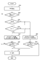
- FIG. 5 shows an example of an operation flow regarding BFD and BFR of the UE 200 according to Operation Example 1.
- UE200 sets TRP (S10).
- the UE 200 may set multiple TRPs (here, TRP1, 2).
- TRP1, 2 may be interpreted as corresponding, for example, to the transmitting/receiving points 101, 102 shown in FIG.
- the UE 200 determines the presence or absence of beam failure detection (BFD) in the lower layer (S20).
- the lower layers may include layer 1 (PHY) and medium access control layer (MAC).
- the UE 200 determines the set number of TRPs (S25). Here, the UE 200 determines whether one or two TRPs are set.
- the UE 200 determines whether or not BFD has occurred in TRP1 (S30). In the case of TRP1, the UE 200 starts a timer for TRP1, specifically beamFailureDetectionTimer_TRP1, and increments a counter for TRP1, specifically BFI_COUNTER_TRP1 (S40).
- the UE 200 starts the timer for TRP1, specifically beamFailureDetectionTimer_TRP2, and increments the value of the counter for TRP1, specifically BFI_COUNTER_TRP2 (S50). Note that when it is determined that there are two TRPs that have been set, the processes of steps S40 and S50 may be executed respectively.
- the UE 200 determines whether or not the counter value satisfies a predetermined condition (S60, S65), and if the condition is satisfied, may execute BFR (S70).
- a predetermined condition may be, for example, when BFI_COUNTER_TRP1>beamFailureInstanceMaxCount and/or BFI_COUNTER_TRP2>beamFailureInstanceMaxCount are satisfied in SpCell.
- the UE 200 may perform a random access (RA) procedure.
- RA random access
- the random access procedure may be interpreted as a type of initial access procedure, and in a broader sense, it is interpreted as BFR for each cell including PRACH transmission in PCell/PSCell specified in 3GPP Release 15/16. may be
- BFR is, as described above, when a failure occurs in the beam BM during communication due to factors such as blocking of the propagation path, a beam failure recovery request is sent to the gNB100 using the beam BM that is not in failure. may be interpreted as a procedure for early recovery of the failed beam BM.
- UE 200 applies BFR to both the cell corresponding to TRP1 (the cell may be formed by TRP1, the same shall apply hereinafter) and the cell corresponding to TRP2. may be executed.
- UE 200 transmits BFR for each cell specified in 3GPP Release 16 (in particular, BFR of SCell and/or BFR MAC CE (Control Element) transmission BFR) may be performed.
- the UE 200 may reset both BFI_COUNTER_TRP1 and BFI_COUNTER_TRP2, or may reset only one of the corresponding counters.
- the UE 200 may also start an existing beamFailureDetectionTimer (that is, a non-TRP-specific timer for each cell) at the timing of starting beamFailureDetectionTimer_TRP1 or beamFailureDetectionTimer_TRP2.
- an existing beamFailureDetectionTimer that is, a non-TRP-specific timer for each cell
- the UE 200 does not have to activate the existing beamFailureDetectionTimer at the timing of activating beamFailureDetectionTimer_TRP1 or beamFailureDetectionTimer_TRP2.
- the UE 200 may expire beamFailureDetectionTimer_TRP1 and beamFailureDetectionTimer_TRP2 and reset both BFI_COUNTER_TRP1 and BFI_COUNTER_TRP2 to "0".
- the UE 200 may expire the existing beamFailureDetectionTimer and reset the existing per-cell BFI_COUNTER to '0' when beamFailureDetectionTimer_TRP1 or beamFailureDetectionTimer_TRP2 expires.
- FIG. 6 shows an example of a beam failure-related RRC communication sequence according to Operation Example 2 and Operation Example 3.
- FIG. 6 shows an example of a beam failure-related RRC communication sequence according to Operation Example 2 and Operation Example 3.
- the network may transmit serving cell configuration information (ServingCellConfig) to UE 200 (step 1).
- servingCellConfig serving cell configuration information
- the UE 200 configures the serving cell including the beam BM (step 2).
- multiple TRPs and beams BM may be transmitted and received, as described above.
- the UE 200 detects a beam failure based on the reception quality (RSRP, etc.) of the beam BM (step 3).
- the UE 200 may send a report on beam failure to the network (step 4).
- a beam failure report may be included in at least one of RLF report, MCGFailureInfo or SCGFailureInfo.
- the rlf-cause/failure type of RLF report, MCGFailureInfo and SCGFailureInfo specified in 3GPP Release 16 specifies the cause value beamFailureRecoveryFailure.
- the cause value cannot express beamFailureRecoveryFailure in multiple TRPs such as TRP1 and TRP2 at the same time.
- beamFailureRecoveryFailureForMultiTRP (may be tentatively named) is added as the rlf-cause/failure type of RLF report, MCGFailureInfo, and SCGFailureInfo to express that beam failure recovery (BFR) has failed in multiple TRPs at the same time.
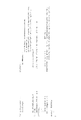
- FIG. 7 shows a configuration example of the RLF report according to Operation Example 2.
- beamFailureRecoveryFailureForMultiTRP for multiple TRPs may be added to beamFailureRecoveryFailure (underlined part) of RLF report defined in 3GPP TS38.331.
- FIG. 8 shows a configuration example of MCGFailureInfo (FailureReportMCG) according to Operation Example 2
- FIG. 9 shows a configuration example of SCGFailureInfo (FailureReportSCG) according to Operation Example 2.
- beamFailureRecoveryFailureForMultiTRP for multiple TRPs may be added to beamFailureRecoveryFailure (underlined) of FailureReportMCG and FailureReportSCG defined in 3GPP TS38.331.
- the UE 200 may control the beam BM according to the candidateBeamRS for each TRP.
- the candidate beam included in beamFailureRecoverySCellConfig is set for each cell, but in the mTRP environment, the candidate beam included in beamFailureRecoverySCellConfig must be set for each TRP.
- candidateBeamRS for each TRP (which may be based on the TRP ID or RS set ID) may be set as information included in beamFailureRecoverySCellConfig.
- FIG. 10 shows a configuration example of beamFailureRecoverySCellConfig according to Operation Example 3.
- beamFailureRecoverySCellConfig defined in 3GPP TS38.331 may include candidateBeamRS for each TRP, specifically CandidateBeamRSPerTRP (underlined part).
- beamFailureRecoverySCellConfig may be included in ServingCellConfig, and candidate beam may be interpreted as a candidate beam BM that UE 200 can use.
- the UE 200 can perform beam failure detection and/or recovery using counters and timers for each TRP in an mTRP environment.
- the relationship between the conventional counters and timers for each cell becomes clear, and the UE 200 appropriately detects and restores beam failures in the mTRP environment, that is, , can perform beam management.
- the UE 200 may perform an initial access such as an RA procedure including BFR when the value of either BFI_COUNTER_TRP1 or BFI_COUNTER_TRP2 in SpCell exceeds a threshold. Also, when the value of either BFI_COUNTER_TRP1 or BFI_COUNTER_TRP2 in SCell exceeds a threshold, UE 200 may perform BFR including BFR MAC CE transmission. As such, the UE 200 can more quickly respond to beam failures in the mTRP environment.
- the UE 200 can transmit a report (beamFailureRecoveryFailureForMultiTRP) indicating beam failure recovery failure for multiple TRPs. Also, the UE 200 can receive a setting (candidateBeamRS) indicating a candidate beam for each of the multiple TRPs. Therefore, precise beam control in the mTRP environment can be realized.
- a report beamFailureRecoveryFailureForMultiTRP
- can receive a setting candidateBeamRS
- each TRP may form a cell, or a radio base station including a plurality of TRPs may form a cell.
- configure, activate, update, indicate, enable, specify, and select may be read interchangeably. good.
- link, associate, correspond, and map may be read interchangeably to allocate, assign, monitor. , map, may also be read interchangeably.
- precoding "precoding weight”
- QCL quadsi-co-location
- TCI state Transmission Configuration Indication state
- spatialal patial relation
- spatialal domain filter "transmission power”
- phase rotation "antenna port
- antenna port group "layer”
- number of layers Terms such as “rank”, “resource”, “resource set”, “resource group”, “beam”, “beam width”, “beam angle”, “antenna”, “antenna element”, “panel” are interchangeable. can be used as intended.
- each functional block may be implemented using one device physically or logically coupled, or directly or indirectly using two or more physically or logically separate devices (e.g. , wired, wireless, etc.) and may be implemented using these multiple devices.
- a functional block may be implemented by combining software in the one device or the plurality of devices.
- Functions include judging, determining, determining, calculating, calculating, processing, deriving, investigating, searching, checking, receiving, transmitting, outputting, accessing, resolving, selecting, choosing, establishing, comparing, assuming, expecting, assuming, Broadcasting, notifying, communicating, forwarding, configuring, reconfiguring, allocating, mapping, assigning, etc. can't
- a functional block (component) that performs transmission is called a transmitting unit or transmitter.
- the implementation method is not particularly limited.
- FIG. 11 is a diagram showing an example of the hardware configuration of the device. As shown in FIG. 11, the device may be configured as a computing device including a processor 1001, a memory 1002, a storage 1003, a communication device 1004, an input device 1005, an output device 1006, a bus 1007, and the like.
- the term "apparatus” can be read as a circuit, device, unit, or the like.
- the hardware configuration of the device may be configured to include one or more of each device shown in the figure, or may be configured without some of the devices.
- Each functional block of the device (see Fig. 2.3) is realized by any hardware element of the computer device or a combination of the hardware elements.
- each function of the device is implemented by causing the processor 1001 to perform calculations, controlling communication by the communication device 1004, and controlling the It is realized by controlling at least one of data reading and writing in 1002 and storage 1003 .
- a processor 1001 operates an operating system and controls the entire computer.
- the processor 1001 may be configured with a central processing unit (CPU) including interfaces with peripheral devices, a controller, arithmetic units, registers, and the like.
- CPU central processing unit
- the processor 1001 reads programs (program codes), software modules, data, etc. from at least one of the storage 1003 and the communication device 1004 to the memory 1002, and executes various processes according to them.
- programs program codes
- software modules software modules
- data etc.
- the various processes described above may be executed by one processor 1001, or may be executed by two or more processors 1001 simultaneously or sequentially.
- Processor 1001 may be implemented by one or more chips. Note that the program may be transmitted from a network via an electric communication line.
- the memory 1002 is a computer-readable recording medium, and is composed of at least one of Read Only Memory (ROM), Erasable Programmable ROM (EPROM), Electrically Erasable Programmable ROM (EEPROM), Random Access Memory (RAM), etc. may be
- ROM Read Only Memory
- EPROM Erasable Programmable ROM
- EEPROM Electrically Erasable Programmable ROM
- RAM Random Access Memory
- the memory 1002 may also be called a register, cache, main memory (main storage device), or the like.
- the memory 1002 can store programs (program code), software modules, etc. capable of executing a method according to an embodiment of the present disclosure.
- the storage 1003 is a computer-readable recording medium, for example, an optical disc such as a Compact Disc ROM (CD-ROM), a hard disk drive, a flexible disc, a magneto-optical disc (for example, a compact disc, a digital versatile disc, a Blu-ray disk), smart card, flash memory (eg, card, stick, key drive), floppy disk, magnetic strip, and/or the like.
- Storage 1003 may also be referred to as an auxiliary storage device.
- the recording medium described above may be, for example, a database, server, or other suitable medium including at least one of memory 1002 and storage 1003 .
- the communication device 1004 is hardware (transmitting/receiving device) for communicating between computers via at least one of a wired network and a wireless network, and is also called a network device, a network controller, a network card, a communication module, or the like.
- the communication device 1004 includes a high-frequency switch, duplexer, filter, frequency synthesizer, etc., for realizing at least one of frequency division duplex (FDD) and time division duplex (TDD).
- FDD frequency division duplex
- TDD time division duplex
- the input device 1005 is an input device (for example, keyboard, mouse, microphone, switch, button, sensor, etc.) that receives input from the outside.
- the output device 1006 is an output device (eg, display, speaker, LED lamp, etc.) that outputs to the outside. Note that the input device 1005 and the output device 1006 may be integrated (for example, a touch panel).
- each device such as the processor 1001 and the memory 1002 is connected by a bus 1007 for communicating information.
- the bus 1007 may be configured using a single bus, or may be configured using different buses between devices.
- the device includes hardware such as a microprocessor, digital signal processor (DSP), application specific integrated circuit (ASIC), programmable logic device (PLD), field programmable gate array (FPGA), etc.
- DSP digital signal processor
- ASIC application specific integrated circuit
- PLD programmable logic device
- FPGA field programmable gate array
- notification of information is not limited to the aspects/embodiments described in the present disclosure, and may be performed using other methods.
- the notification of information may include physical layer signaling (e.g., Downlink Control Information (DCI), Uplink Control Information (UCI), higher layer signaling (e.g., RRC signaling, Medium Access Control (MAC) signaling, broadcast information (Master Information Block (MIB), System Information Block (SIB), other signals, or combinations thereof, and RRC signaling may also be referred to as RRC messages, e.g., RRC Connection Setup ) message, RRC Connection Reconfiguration message, or the like.
- DCI Downlink Control Information
- UCI Uplink Control Information
- RRC signaling e.g., RRC signaling, Medium Access Control (MAC) signaling, broadcast information (Master Information Block (MIB), System Information Block (SIB), other signals, or combinations thereof
- RRC signaling may also be referred to as RRC messages, e.g., RRC Connection Setup ) message, R
- LTE Long Term Evolution
- LTE-A LTE-Advanced
- SUPER 3G IMT-Advanced
- 4G 4th generation mobile communication system
- 5G 5th generation mobile communication system
- Future Radio Access FAA
- New Radio NR
- W-CDMA registered trademark
- GSM registered trademark
- CDMA2000 Code Division Multiple Access 2000
- UMB Ultra Mobile Broadband
- IEEE 802.11 Wi-Fi (registered trademark)
- IEEE 802.16 WiMAX®
- IEEE 802.20 Ultra-WideBand (UWB), Bluetooth®, other suitable systems, and/or next-generation systems enhanced therefrom.
- a plurality of systems may be applied in combination (for example, a combination of at least one of LTE and LTE-A and 5G).
- a specific operation that is performed by a base station in the present disclosure may be performed by its upper node in some cases.
- various operations performed for communication with a terminal may be performed by the base station and other network nodes other than the base station (e.g. MME or S-GW, etc., but not limited to).
- MME or S-GW network nodes
- the case where there is one network node other than the base station is exemplified above, it may be a combination of a plurality of other network nodes (for example, MME and S-GW).
- Information, signals can be output from a higher layer (or a lower layer) to a lower layer (or a higher layer). It may be input and output via multiple network nodes.
- Input/output information may be stored in a specific location (for example, memory) or managed using a management table. Input and output information may be overwritten, updated, or appended. The output information may be deleted. The entered information may be transmitted to other devices.
- the determination may be made by a value represented by one bit (0 or 1), by a true/false value (Boolean: true or false), or by numerical comparison (for example, a predetermined value).
- notification of predetermined information is not limited to being performed explicitly, but may be performed implicitly (for example, not notifying the predetermined information). good too.
- Software whether referred to as software, firmware, middleware, microcode, hardware description language or otherwise, includes instructions, instruction sets, code, code segments, program code, programs, subprograms, and software modules. , applications, software applications, software packages, routines, subroutines, objects, executables, threads of execution, procedures, functions, and the like.
- software, instructions, information, etc. may be transmitted and received via a transmission medium.
- the Software uses wired technology (coaxial cable, fiber optic cable, twisted pair, Digital Subscriber Line (DSL), etc.) and/or wireless technology (infrared, microwave, etc.) to access websites, Wired and/or wireless technologies are included within the definition of transmission medium when sent from a server or other remote source.
- wired technology coaxial cable, fiber optic cable, twisted pair, Digital Subscriber Line (DSL), etc.
- wireless technology infrared, microwave, etc.
- data, instructions, commands, information, signals, bits, symbols, chips, etc. may refer to voltages, currents, electromagnetic waves, magnetic fields or magnetic particles, light fields or photons, or any of these. may be represented by a combination of
- the channel and/or symbols may be signaling.
- a signal may also be a message.
- a component carrier may also be called a carrier frequency, a cell, a frequency carrier, or the like.
- system and “network” used in this disclosure are used interchangeably.
- information, parameters, etc. described in the present disclosure may be expressed using absolute values, may be expressed using relative values from a predetermined value, or may be expressed using other corresponding information.
- radio resources may be indexed.
- base station BS
- radio base station fixed station
- NodeB NodeB
- eNodeB eNodeB
- gNodeB gNodeB
- a base station may also be referred to by terms such as macrocell, small cell, femtocell, picocell, and the like.
- a base station can accommodate one or more (eg, three) cells (also called sectors). When a base station accommodates multiple cells, the overall coverage area of the base station can be partitioned into multiple smaller areas, each smaller area corresponding to a base station subsystem (e.g., a small indoor base station (Remote Radio)). Head: RRH) can also provide communication services.
- a base station subsystem e.g., a small indoor base station (Remote Radio)
- Head: RRH can also provide communication services.
- cell refers to part or all of the coverage area of at least one of a base station and base station subsystem that provides communication services in this coverage.
- MS Mobile Station
- UE User Equipment
- a mobile station is defined by those skilled in the art as a subscriber station, mobile unit, subscriber unit, wireless unit, remote unit, mobile device, wireless device, wireless communication device, remote device, mobile subscriber station, access terminal, mobile terminal, wireless It may also be called a terminal, remote terminal, handset, user agent, mobile client, client, or some other suitable term.
- At least one of the base station and mobile station may be called a transmitting device, a receiving device, a communication device, or the like.
- At least one of the base station and the mobile station may be a device mounted on a mobile object, the mobile object itself, or the like.
- the mobile body may be a vehicle (e.g., car, airplane, etc.), an unmanned mobile body (e.g., drone, self-driving car, etc.), or a robot (manned or unmanned ).
- at least one of the base station and the mobile station includes devices that do not necessarily move during communication operations.
- at least one of the base station and mobile station may be an Internet of Things (IoT) device such as a sensor.
- IoT Internet of Things
- the base station in the present disclosure may be read as a mobile station (user terminal, hereinafter the same).
- communication between a base station and a mobile station is replaced with communication between multiple mobile stations (for example, Device-to-Device (D2D), Vehicle-to-Everything (V2X), etc.)
- the mobile station may have the functions that the base station has.
- words such as "up” and “down” may be replaced with words corresponding to inter-terminal communication (for example, "side”).
- uplink channels, downlink channels, etc. may be read as side channels.
- a radio frame may consist of one or more frames in the time domain. Each frame or frames in the time domain may be referred to as a subframe. A subframe may also consist of one or more slots in the time domain. A subframe may be a fixed time length (eg, 1 ms) independent of numerology.
- a numerology may be a communication parameter that applies to the transmission and/or reception of a signal or channel. Numerology, for example, subcarrier spacing (SCS), bandwidth, symbol length, cyclic prefix length, transmission time interval (TTI), number of symbols per TTI, radio frame structure, transmission and reception specific filtering operations performed by the receiver in the frequency domain, specific windowing operations performed by the transceiver in the time domain, and/or the like.
- SCS subcarrier spacing
- TTI transmission time interval
- number of symbols per TTI radio frame structure
- transmission and reception specific filtering operations performed by the receiver in the frequency domain specific windowing operations performed by the transceiver in the time domain, and/or the like.
- a slot may consist of one or more symbols (Orthogonal Frequency Division Multiplexing (OFDM) symbols, Single Carrier Frequency Division Multiple Access (SC-FDMA) symbols, etc.) in the time domain.
- OFDM Orthogonal Frequency Division Multiplexing
- SC-FDMA Single Carrier Frequency Division Multiple Access
- a slot may be a unit of time based on numerology.
- a slot may contain multiple mini-slots. Each minislot may consist of one or more symbols in the time domain. A minislot may also be referred to as a subslot. A minislot may consist of fewer symbols than a slot.
- a PDSCH (or PUSCH) that is transmitted in time units larger than a minislot may be referred to as PDSCH (or PUSCH) mapping type A.
- PDSCH (or PUSCH) transmitted using minislots may be referred to as PDSCH (or PUSCH) mapping type B.
- Radio frames, subframes, slots, minislots and symbols all represent time units when transmitting signals. Radio frames, subframes, slots, minislots and symbols may be referred to by other corresponding designations.
- one subframe may be called a transmission time interval (TTI)
- TTI transmission time interval
- multiple consecutive subframes may be called a TTI
- one slot or one minislot may be called a TTI. That is, at least one of the subframe and TTI may be a subframe (1ms) in existing LTE, may be a period shorter than 1ms (eg, 1-13 symbols), or a period longer than 1ms may be Note that the unit representing the TTI may be called a slot, minislot, or the like instead of a subframe.
- TTI refers to, for example, the minimum scheduling time unit in wireless communication.
- a base station performs scheduling to allocate radio resources (frequency bandwidth, transmission power, etc. that can be used by each user terminal) to each user terminal on a TTI basis.
- radio resources frequency bandwidth, transmission power, etc. that can be used by each user terminal
- the TTI may be a transmission time unit for channel-encoded data packets (transport blocks), code blocks, codewords, etc., or may be a processing unit for scheduling, link adaptation, etc. Note that when a TTI is given, the time interval (for example, the number of symbols) in which transport blocks, code blocks, codewords, etc. are actually mapped may be shorter than the TTI.
- one slot or one minislot is called a TTI
- one or more TTIs may be the minimum scheduling time unit.
- the number of slots (the number of mini-slots) constituting the minimum time unit of the scheduling may be controlled.
- a TTI with a time length of 1 ms may be called a normal TTI (TTI in LTE Rel.8-12), normal TTI, long TTI, normal subframe, normal subframe, long subframe, slot, etc.
- TTI that is shorter than a regular TTI may also be called a shortened TTI, a short TTI, a partial or fractional TTI, a shortened subframe, a short subframe, a minislot, a subslot, a slot, and so on.
- long TTI for example, normal TTI, subframe, etc.
- short TTI for example, shortened TTI, etc.
- a TTI having a TTI length greater than or equal to this value may be read as a replacement.
- a resource block is a resource allocation unit in the time domain and frequency domain, and may include one or more consecutive subcarriers in the frequency domain.
- the number of subcarriers included in an RB may be the same regardless of neurology, and may be 12, for example.
- the number of subcarriers included in an RB may be determined based on neumerology.
- the time domain of an RB may include one or more symbols and may be 1 slot, 1 minislot, 1 subframe, or 1 TTI long.
- One TTI, one subframe, etc. may each consist of one or more resource blocks.
- One or more RBs are physical resource blocks (Physical RB: PRB), sub-carrier groups (SCG), resource element groups (REG), PRB pairs, RB pairs, etc. may be called.
- PRB Physical resource blocks
- SCG sub-carrier groups
- REG resource element groups
- PRB pairs RB pairs, etc.
- a resource block may be composed of one or more resource elements (Resource Element: RE).
- RE resource elements
- 1 RE may be a radio resource region of 1 subcarrier and 1 symbol.
- a Bandwidth Part (which may also be called a Bandwidth Part) represents a subset of contiguous common resource blocks (RBs) for a neumerology in a carrier. good.
- the common RB may be identified by an RB index based on the common reference point of the carrier.
- PRBs may be defined in a BWP and numbered within that BWP.
- BWP may include BWP for UL (UL BWP) and BWP for DL (DL BWP).
- BWP may include BWP for UL (UL BWP) and BWP for DL (DL BWP).
- One or more BWPs may be configured in one carrier for a UE.
- At least one of the configured BWPs may be active, and the UE may not expect to transmit or receive a given signal/channel outside the active BWP.
- BWP bitmap
- radio frames, subframes, slots, minislots and symbols described above are only examples.
- the number of subframes included in a radio frame the number of slots per subframe or radio frame, the number of minislots included in a slot, the number of symbols and RBs included in a slot or minislot, the number of Configurations such as the number of subcarriers and the number of symbols in a TTI, symbol length, cyclic prefix (CP) length, etc.
- CP cyclic prefix
- connection means any direct or indirect connection or coupling between two or more elements, It can include the presence of one or more intermediate elements between two elements being “connected” or “coupled.” Couplings or connections between elements may be physical, logical, or a combination thereof. For example, “connection” may be read as "access”.
- two elements are defined using at least one of one or more wires, cables and printed electrical connections and, as some non-limiting and non-exhaustive examples, in the radio frequency domain. , electromagnetic energy having wavelengths in the microwave and light (both visible and invisible) regions, and the like.
- the reference signal can also be abbreviated as Reference Signal (RS), and may also be called Pilot depending on the applicable standard.
- RS Reference Signal
- any reference to elements using the "first,” “second,” etc. designations used in this disclosure does not generally limit the quantity or order of those elements. These designations may be used in this disclosure as a convenient method of distinguishing between two or more elements. Thus, references to first and second elements do not imply that only two elements may be employed therein or that the first element must precede the second element in any way.
- determining and “determining” used in this disclosure may encompass a wide variety of actions.
- “Judgement” and “determination” are, for example, judging, calculating, computing, processing, deriving, investigating, looking up, searching, inquiring (eg, lookup in a table, database, or other data structure), ascertaining as “judged” or “determined”, and the like.
- "judgment” and “determination” are used for receiving (e.g., receiving information), transmitting (e.g., transmitting information), input, output, access (accessing) (for example, accessing data in memory) may include deeming that a "judgment” or “decision” has been made.
- judgment and “decision” are considered to be “judgment” and “decision” by resolving, selecting, choosing, establishing, comparing, etc. can contain.
- judgment and “decision” may include considering that some action is “judgment” and “decision”.
- judgment (decision) may be read as “assuming”, “expecting”, “considering”, or the like.
- a and B are different may mean “A and B are different from each other.”
- the term may also mean that "A and B are different from C”.
- Terms such as “separate,” “coupled,” etc. may also be interpreted in the same manner as “different.”
- Radio communication system 20 NG-RAN 100 gNB 110 radio communication unit 120 RRC processing unit 130 TRP setting unit 140 control unit 200 UE 210 wireless communication unit 220 RRC processing unit 230 beam setting unit 240 control unit 1001 processor 1002 memory 1003 storage 1004 communication device 1005 input device 1006 output device 1007 bus
Landscapes
- Engineering & Computer Science (AREA)
- Computer Networks & Wireless Communication (AREA)
- Signal Processing (AREA)
- Mobile Radio Communication Systems (AREA)
Priority Applications (4)
| Application Number | Priority Date | Filing Date | Title |
|---|---|---|---|
| PCT/JP2021/023688 WO2022269778A1 (ja) | 2021-06-22 | 2021-06-22 | 端末及び無線通信方法 |
| JP2023529297A JP7779911B2 (ja) | 2021-06-22 | 2021-06-22 | 端末及び無線通信方法 |
| CN202180099416.1A CN117529967A (zh) | 2021-06-22 | 2021-06-22 | 终端以及无线通信方法 |
| EP21947064.8A EP4362602A4 (en) | 2021-06-22 | 2021-06-22 | WIRELESS COMMUNICATION TERMINAL AND METHOD |
Applications Claiming Priority (1)
| Application Number | Priority Date | Filing Date | Title |
|---|---|---|---|
| PCT/JP2021/023688 WO2022269778A1 (ja) | 2021-06-22 | 2021-06-22 | 端末及び無線通信方法 |
Publications (1)
| Publication Number | Publication Date |
|---|---|
| WO2022269778A1 true WO2022269778A1 (ja) | 2022-12-29 |
Family
ID=84545359
Family Applications (1)
| Application Number | Title | Priority Date | Filing Date |
|---|---|---|---|
| PCT/JP2021/023688 Ceased WO2022269778A1 (ja) | 2021-06-22 | 2021-06-22 | 端末及び無線通信方法 |
Country Status (4)
| Country | Link |
|---|---|
| EP (1) | EP4362602A4 (https=) |
| JP (1) | JP7779911B2 (https=) |
| CN (1) | CN117529967A (https=) |
| WO (1) | WO2022269778A1 (https=) |
Cited By (1)
| Publication number | Priority date | Publication date | Assignee | Title |
|---|---|---|---|---|
| CN120980595A (zh) * | 2024-05-10 | 2025-11-18 | 荣耀终端股份有限公司 | 一种触发波束上报、波束管理的方法和装置 |
Citations (1)
| Publication number | Priority date | Publication date | Assignee | Title |
|---|---|---|---|---|
| WO2020255424A1 (ja) * | 2019-06-21 | 2020-12-24 | 株式会社Nttドコモ | 端末 |
Family Cites Families (2)
| Publication number | Priority date | Publication date | Assignee | Title |
|---|---|---|---|---|
| EP3777439A1 (en) * | 2018-04-03 | 2021-02-17 | IDAC Holdings, Inc. | Methods for channel access management |
| CN111937437B (zh) * | 2018-04-06 | 2023-10-03 | 上海诺基亚贝尔股份有限公司 | 用于无线通信系统中的波束故障的装置、方法和介质 |
-
2021
- 2021-06-22 WO PCT/JP2021/023688 patent/WO2022269778A1/ja not_active Ceased
- 2021-06-22 CN CN202180099416.1A patent/CN117529967A/zh active Pending
- 2021-06-22 EP EP21947064.8A patent/EP4362602A4/en active Pending
- 2021-06-22 JP JP2023529297A patent/JP7779911B2/ja active Active
Patent Citations (1)
| Publication number | Priority date | Publication date | Assignee | Title |
|---|---|---|---|---|
| WO2020255424A1 (ja) * | 2019-06-21 | 2020-12-24 | 株式会社Nttドコモ | 端末 |
Non-Patent Citations (6)
| Title |
|---|
| 3GPP: "Beam failure with mTRP", R2-2105870, 3GPP TSG-RAN WG2 MEETING #114 ELECTRONIC, May 2021 (2021-05-01) |
| 3GPP: "Revised WID: Further enhancements on MIMO for NR", RP-202024, 3GPP TSG RAN MEETING #89E, September 2020 (2020-09-01) |
| CMCC: "Enhancements on beam management for multi-TRP", 3GPP DRAFT; R1-2008003, 3RD GENERATION PARTNERSHIP PROJECT (3GPP), MOBILE COMPETENCE CENTRE ; 650, ROUTE DES LUCIOLES ; F-06921 SOPHIA-ANTIPOLIS CEDEX ; FRANCE, vol. RAN WG1, no. e-Meeting; 20201026 - 20201113, 23 October 2020 (2020-10-23), Mobile Competence Centre ; 650, route des Lucioles ; F-06921 Sophia-Antipolis Cedex ; France , XP051945304 * |
| LG ELECTRONICS: "Enhancements on beam management for multi-TRP", 3GPP DRAFT; R1-2103507, 3RD GENERATION PARTNERSHIP PROJECT (3GPP), MOBILE COMPETENCE CENTRE ; 650, ROUTE DES LUCIOLES ; F-06921 SOPHIA-ANTIPOLIS CEDEX ; FRANCE, vol. RAN WG1, no. e-Meeting; 20210412 - 20210420, 7 April 2021 (2021-04-07), Mobile Competence Centre ; 650, route des Lucioles ; F-06921 Sophia-Antipolis Cedex ; France, XP052178226 * |
| OPPO: "Discussion on RAN2 specification impacts of TRP-based BFR", 3GPP DRAFT; R2-2105341, 3RD GENERATION PARTNERSHIP PROJECT (3GPP), MOBILE COMPETENCE CENTRE ; 650, ROUTE DES LUCIOLES ; F-06921 SOPHIA-ANTIPOLIS CEDEX ; FRANCE, vol. RAN WG2, no. electronic; 20210501, 11 May 2021 (2021-05-11), Mobile Competence Centre ; 650, route des Lucioles ; F-06921 Sophia-Antipolis Cedex ; France , XP052006976 * |
| See also references of EP4362602A4 |
Cited By (1)
| Publication number | Priority date | Publication date | Assignee | Title |
|---|---|---|---|---|
| CN120980595A (zh) * | 2024-05-10 | 2025-11-18 | 荣耀终端股份有限公司 | 一种触发波束上报、波束管理的方法和装置 |
Also Published As
| Publication number | Publication date |
|---|---|
| JP7779911B2 (ja) | 2025-12-03 |
| CN117529967A (zh) | 2024-02-06 |
| EP4362602A4 (en) | 2025-04-23 |
| EP4362602A1 (en) | 2024-05-01 |
| JPWO2022269778A1 (https=) | 2022-12-29 |
Similar Documents
| Publication | Publication Date | Title |
|---|---|---|
| JP7279044B2 (ja) | 端末、無線通信方法及びシステム | |
| JP7320762B2 (ja) | 端末、無線通信方法及びシステム | |
| JP7323612B2 (ja) | 端末、無線通信方法及びシステム | |
| JP7313369B2 (ja) | 端末、無線通信方法及びシステム | |
| JP7248681B2 (ja) | 端末、無線通信方法、基地局及びシステム | |
| JPWO2020012594A1 (ja) | ユーザ端末 | |
| JPWO2019203187A1 (ja) | ユーザ端末及び無線通信方法 | |
| WO2020012618A1 (ja) | ユーザ端末 | |
| JP7223026B2 (ja) | 端末、基地局、無線通信システム、及び通信方法 | |
| JPWO2019220649A1 (ja) | ユーザ端末及び無線通信方法 | |
| JP7762200B2 (ja) | 端末、無線通信方法、基地局及びシステム | |
| WO2020026455A1 (ja) | ユーザ端末および無線通信方法 | |
| JP7558958B2 (ja) | 端末 | |
| WO2020054074A1 (ja) | ユーザ端末及び無線通信方法 | |
| JPWO2020053977A1 (ja) | ユーザ端末及び無線通信方法 | |
| WO2022220071A1 (ja) | 端末及び無線通信方法 | |
| US12058664B2 (en) | Terminal, radio communication method, base station, and system using MIMO layers | |
| JP7818575B2 (ja) | 端末、無線通信方法及びシステム | |
| JP7301978B2 (ja) | 端末、通信方法、基地局及びシステム | |
| JP7779911B2 (ja) | 端末及び無線通信方法 | |
| WO2022079813A1 (ja) | 端末、無線通信方法及び基地局 | |
| JP7564230B2 (ja) | 端末及び無線通信方法 | |
| WO2022234654A1 (ja) | 端末及び無線通信方法 | |
| WO2023013028A1 (ja) | 端末及び無線通信方法 | |
| WO2022185549A1 (ja) | 通信装置及び通信方法 |
Legal Events
| Date | Code | Title | Description |
|---|---|---|---|
| 121 | Ep: the epo has been informed by wipo that ep was designated in this application |
Ref document number: 21947064 Country of ref document: EP Kind code of ref document: A1 |
|
| WWE | Wipo information: entry into national phase |
Ref document number: 202180099416.1 Country of ref document: CN Ref document number: 2023529297 Country of ref document: JP |
|
| WWE | Wipo information: entry into national phase |
Ref document number: 2021947064 Country of ref document: EP |
|
| NENP | Non-entry into the national phase |
Ref country code: DE |
|
| ENP | Entry into the national phase |
Ref document number: 2021947064 Country of ref document: EP Effective date: 20240122 |