WO2022269736A1 - 画像処理装置、マニピュレータシステム、画像処理方法及び表示方法 - Google Patents
画像処理装置、マニピュレータシステム、画像処理方法及び表示方法 Download PDFInfo
- Publication number
- WO2022269736A1 WO2022269736A1 PCT/JP2021/023516 JP2021023516W WO2022269736A1 WO 2022269736 A1 WO2022269736 A1 WO 2022269736A1 JP 2021023516 W JP2021023516 W JP 2021023516W WO 2022269736 A1 WO2022269736 A1 WO 2022269736A1
- Authority
- WO
- WIPO (PCT)
- Prior art keywords
- bending
- angle
- rotation
- image
- processing unit
- Prior art date
- Legal status (The legal status is an assumption and is not a legal conclusion. Google has not performed a legal analysis and makes no representation as to the accuracy of the status listed.)
- Ceased
Links
Images









Classifications
-
- A—HUMAN NECESSITIES
- A61—MEDICAL OR VETERINARY SCIENCE; HYGIENE
- A61B—DIAGNOSIS; SURGERY; IDENTIFICATION
- A61B1/00—Instruments for performing medical examinations of the interior of cavities or tubes of the body by visual or photographical inspection, e.g. endoscopes; Illuminating arrangements therefor
- A61B1/005—Flexible endoscopes
- A61B1/009—Flexible endoscopes with bending or curvature detection of the insertion part
-
- G—PHYSICS
- G06—COMPUTING OR CALCULATING; COUNTING
- G06T—IMAGE DATA PROCESSING OR GENERATION, IN GENERAL
- G06T19/00—Manipulating three-dimensional [3D] models or images for computer graphics
- G06T19/20—Editing of three-dimensional [3D] images, e.g. changing shapes or colours, aligning objects or positioning parts
-
- A—HUMAN NECESSITIES
- A61—MEDICAL OR VETERINARY SCIENCE; HYGIENE
- A61B—DIAGNOSIS; SURGERY; IDENTIFICATION
- A61B1/00—Instruments for performing medical examinations of the interior of cavities or tubes of the body by visual or photographical inspection, e.g. endoscopes; Illuminating arrangements therefor
- A61B1/00002—Operational features of endoscopes
- A61B1/00004—Operational features of endoscopes characterised by electronic signal processing
- A61B1/00009—Operational features of endoscopes characterised by electronic signal processing of image signals during a use of endoscope
-
- A—HUMAN NECESSITIES
- A61—MEDICAL OR VETERINARY SCIENCE; HYGIENE
- A61B—DIAGNOSIS; SURGERY; IDENTIFICATION
- A61B1/00—Instruments for performing medical examinations of the interior of cavities or tubes of the body by visual or photographical inspection, e.g. endoscopes; Illuminating arrangements therefor
- A61B1/00002—Operational features of endoscopes
- A61B1/00043—Operational features of endoscopes provided with output arrangements
- A61B1/00045—Display arrangement
- A61B1/0005—Display arrangement combining images e.g. side-by-side, superimposed or tiled
-
- A—HUMAN NECESSITIES
- A61—MEDICAL OR VETERINARY SCIENCE; HYGIENE
- A61B—DIAGNOSIS; SURGERY; IDENTIFICATION
- A61B1/00—Instruments for performing medical examinations of the interior of cavities or tubes of the body by visual or photographical inspection, e.g. endoscopes; Illuminating arrangements therefor
- A61B1/00163—Optical arrangements
- A61B1/00194—Optical arrangements adapted for three-dimensional imaging
-
- A—HUMAN NECESSITIES
- A61—MEDICAL OR VETERINARY SCIENCE; HYGIENE
- A61B—DIAGNOSIS; SURGERY; IDENTIFICATION
- A61B34/00—Computer-aided surgery; Manipulators or robots specially adapted for use in surgery
- A61B34/25—User interfaces for surgical systems
-
- B—PERFORMING OPERATIONS; TRANSPORTING
- B25—HAND TOOLS; PORTABLE POWER-DRIVEN TOOLS; MANIPULATORS
- B25J—MANIPULATORS; CHAMBERS PROVIDED WITH MANIPULATION DEVICES
- B25J18/00—Arms
- B25J18/06—Arms flexible
-
- G—PHYSICS
- G06—COMPUTING OR CALCULATING; COUNTING
- G06T—IMAGE DATA PROCESSING OR GENERATION, IN GENERAL
- G06T15/00—Three-dimensional [3D] image rendering
- G06T15/10—Geometric effects
-
- G—PHYSICS
- G06—COMPUTING OR CALCULATING; COUNTING
- G06T—IMAGE DATA PROCESSING OR GENERATION, IN GENERAL
- G06T19/00—Manipulating three-dimensional [3D] models or images for computer graphics
-
- A—HUMAN NECESSITIES
- A61—MEDICAL OR VETERINARY SCIENCE; HYGIENE
- A61B—DIAGNOSIS; SURGERY; IDENTIFICATION
- A61B34/00—Computer-aided surgery; Manipulators or robots specially adapted for use in surgery
- A61B34/10—Computer-aided planning, simulation or modelling of surgical operations
- A61B2034/101—Computer-aided simulation of surgical operations
- A61B2034/102—Modelling of surgical devices, implants or prosthesis
-
- A—HUMAN NECESSITIES
- A61—MEDICAL OR VETERINARY SCIENCE; HYGIENE
- A61B—DIAGNOSIS; SURGERY; IDENTIFICATION
- A61B90/00—Instruments, implements or accessories specially adapted for surgery or diagnosis and not covered by any of the groups A61B1/00 - A61B50/00, e.g. for luxation treatment or for protecting wound edges
- A61B90/36—Image-producing devices or illumination devices not otherwise provided for
- A61B2090/364—Correlation of different images or relation of image positions in respect to the body
- A61B2090/367—Correlation of different images or relation of image positions in respect to the body creating a 3D dataset from 2D images using position information
-
- G—PHYSICS
- G06—COMPUTING OR CALCULATING; COUNTING
- G06T—IMAGE DATA PROCESSING OR GENERATION, IN GENERAL
- G06T2219/00—Indexing scheme for manipulating 3D models or images for computer graphics
- G06T2219/20—Indexing scheme for editing of 3D models
- G06T2219/2016—Rotation, translation, scaling
Definitions
- the present invention relates to an image processing device, a manipulator system, an image processing method, a display method, and the like.
- Patent Document 1 discloses a navigation technique that displays a virtual 3D model of the bending portion of an endoscope together with an endoscopic image. When an angle operation is performed on the operation unit, the bending angle of the bending portion in the 3D model changes based on the operation input.
- an acquisition unit that acquires shape information about the shape of a manipulator whose shape can be changed; and a processing unit for displaying, wherein the processing unit is related to an image processing device that performs rotation processing for rotating the line-of-sight direction of the virtual camera at a rotation angle corresponding to the shape.
- Another aspect of the present disclosure includes a manipulator provided with an imaging unit at its tip, an image processing device, and a display, wherein the image processing device is configured such that the line-of-sight direction of a virtual camera that follows the imaging direction of the imaging unit to display a CG image of a manipulator model in the display on the display.
- shape information about the shape of a shape-changeable manipulator is obtained, and based on the shape information, the line-of-sight direction of a virtual camera in an object space is rotated at a rotation angle according to the shape. It relates to an image processing method for performing rotation processing to rotate a manipulator model and displaying a CG image of a manipulator model viewed from the virtual camera in the object space on a display.
- Still another aspect of the present disclosure is a display method for displaying a CG image of a manipulator model, wherein the manipulator model is displayed in the line-of-sight direction of a virtual camera that follows the imaging direction of an imaging unit provided at the tip of the manipulator. It relates to a display method for displaying a CG image on a display.
- FIG. 3 is an explanatory diagram of a 3D model configured by a processing unit; The relationship between the bending angle and the rotation angle of the line-of-sight direction in the first embodiment.
- a display example in the first embodiment. 4 is a flowchart of processing in the first embodiment; The relationship between the bending angle and the rotation angle of the line-of-sight direction in the second embodiment.
- 9 is a flowchart of processing in the second embodiment; The relationship between the bending angle and the rotation angle of the line-of-sight direction in the third embodiment.
- 9 is a flowchart of processing in the third embodiment; The flowchart when combining 5th Embodiment with 2nd Embodiment. The flowchart when combining 5th Embodiment with 3rd Embodiment.
- a manipulator model is a three-dimensional model of a manipulator whose shape changes according to manipulation.
- the manipulator is provided with an imaging unit or holds the imaging unit, and the imaging direction of the imaging unit changes depending on the shape change of the manipulator.
- a CG image is an image generated from a three-dimensional model of a manipulator.
- a CG image is two-dimensional information, but it is also called a 3D model or a 3D image in the sense that it is an image of a three-dimensional model.
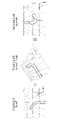
- FIG. 1 shows a display example when a 3D model is displayed with the proximal end of the bending portion of an endoscope fixed. Assume that an endoscopic image is displayed on the left side of the screen and a CG image of the endoscope is displayed on the right side of the screen. CG is an abbreviation for Computer Graphics.
- Xr, Yr, and Zr indicate a coordinate system fixed to the endoscope tip in the real space where the actual endoscope exists, and Zr corresponds to the imaging direction.
- x,y,z is the world coordinate system fixed in the object space in which the 3D model is built.
- the proximal end of the bending portion is fixed so as to face the z direction, and the imaging direction changes according to the bending angle.
- the display image IMA1 shows an example in which the curved portion is straight and not curved.
- the depth direction of the screen always coincides with the imaging direction.
- the imaging direction is the screen depth direction also in the 3D model, and the imaging direction in the endoscopic image and the imaging direction in the 3D model match.
- an intuitive bending operation is possible while viewing the 3D model. That is, the desired bending direction and the operation direction intuitively match.
- the display image IMA2 shows an example in which the bending portion has made a J-turn to the left, that is, an example in which the tip of the endoscope faces the front of the screen. Since the imaging direction of the 3D model is the front side of the screen, the imaging direction of the endoscopic image is opposite to the imaging direction of the 3D model. In this case, it is difficult to intuitively match the desired bending direction with the operation direction. For example, to bend the endoscope further, the tip of the endoscope is moved to the right in the 3D model, but the operation is left bending, and the moving direction of the tip and the operation direction on the 3D model do not match.
- the operator can estimate the bending angle to some extent based on haptic feedback such as the resistance associated with pulling the wire obtained from the dial.
- haptic feedback such as the resistance associated with pulling the wire obtained from the dial.
- the electric endoscope in which the bending drive is motorized, the wire is pulled via a drive unit such as a motor, so it is difficult to obtain haptic feedback from the operation unit held by the operator.
- the electric endoscope it is possible to perform the bending operation using an operation unit such as a touch pad or a remote controller that is separated from the driving unit, and in this case it is even more difficult to obtain haptic feedback.
- FIG. 2 is a configuration example of the image processing apparatus and endoscope system of this embodiment.
- the endoscope system 300 includes an endoscope 10 , a display 20 , a control device 100 , an image processing device 200 and an operation section 400 .
- an electric endoscope will be described here as an example, the method described below can be applied not only to electric endoscopes but also to various endoscopes having a bending portion.
- the endoscope system 300 corresponds to the manipulator system
- the endoscope 10 corresponds to the manipulator.
- the endoscope 10 is also called a scope, is inserted into the body, and images the inside of the body.
- a flexible scope including a flexible insertion section is envisioned.
- the endoscope 10 includes a bending section 40 and an imaging section 30 .
- the bending section 40 is provided at the distal end portion of the endoscope 10 and configured to be bendable according to a bending operation. Bending portion 40 is also referred to as a bending device or bending mechanism.
- the imaging section 30 is an imaging device including an imaging element, an objective lens, and the like, and is provided on the distal end side of the bending section 40 .
- the imaging unit 30 images the inside of the body and transmits the image signal to the control device 100 .
- the endoscope 10 may be further provided with an illumination lens, a forceps port, a suction port, or the like.
- the control device 100 controls the endoscope 10, drives it to bend, and the like.
- the control device 100 is also called a controller, drive device, processor unit, or the like.
- Controller 100 includes motor 101 , drive circuit 102 , sensor 103 and image interface 104 .
- the drive circuit 102 is a circuit that drives the motor 101 , and drives the motor 101 according to operation input from the operation unit 400 .
- the motor 101 pulls a wire connected to the bending section 40 of the endoscope 10 to bend the bending section 40 .
- the bending portion 40 bends at the bending angle corresponding to the operation input.
- the sensor 103 is a sensor that detects the bending angle of the bending portion 40 and transmits the detection signal to the image processing device 200 .
- the sensor 103 is, for example, a rotary encoder that detects the amount of rotation of the motor 101, or an optical sensor that detects the amount of travel of the wire.
- the sensor 103 transmits the detected bending angle to the image processing device 200 .
- FIG. 2 shows an example in which a sensor is provided in the control device 100, but any configuration may be used as long as the bending angle of the bending portion 40 can be detected.
- the bending angle may be acquired from an operation input of a bending operation on the operation unit 400, or the shape of the bending portion 40 may be observed from the outside using a UPD, which is an endoscope shape observation device, and A curvature angle may be obtained from the observed shape.
- the operation unit 400 receives an operation input for operating the endoscope 10, and transmits information of the operation input to the control device 100 by wireless communication.
- the operation unit 400 can receive at least a bending operation.
- the operation unit 400 is, for example, a touch pad, and recognizes a touch or swipe operation on the touch pad as a bending operation.
- the operation unit 400 may include buttons, dials, or the like for the bending operation, and may communicate with the control device 100 not wirelessly but wiredly.
- the image interface 104 receives an image signal from the imaging unit 30 of the endoscope 10 , generates an endoscopic image by image processing the image signal, and transmits image data of the endoscopic image to the image processing device 200 .
- Send to Image processing includes, for example, development processing, tone correction processing, or white balance processing.
- the image interface 104 may transfer the image signal to the image processing apparatus 200, and the image processing apparatus 200 may construct an endoscopic image from the image signal.
- the image processing device 200 generates a 3D model of the endoscope 10 based on the bending angle detected by the sensor 103, and displays the CG image and the endoscope image on the display 20.
- the image processing device 200 is, for example, an information processing device such as a PC or a server.
- the image processing device 200 includes an acquisition section 220 and a processing section 210 .
- various types of hardware are assumed for the acquisition unit 220 , for example, a communication interface provided in the information processing device, or a data interface provided in hardware constituting the processing unit 210 .
- the processing unit 210 is also called a processor, a processing device, a processing circuit, or the like.
- Various types of hardware are assumed for the processing unit 210.
- the image processing apparatus 200 includes a memory (not shown), the memory stores a program describing the processing performed by the processing unit 210, and the processing performed by the processing unit 210 is realized by the processing unit 210 executing the program.
- FIG. 2 shows an example in which the image processing device 200 is provided as an external device of the control device 100 , but the image processing device 200 may be built in the control device 100 .
- the acquisition unit 220 receives image data of the endoscopic image and information on the bending angle from the control device 100 .
- the processing unit 210 generates a 3D model of the endoscope 10 in the object space, and displays a CG image of the endoscope 10 generated based on the 3D model and an endoscope image on the display 20 .
- the endoscopic image is displayed in the first display area of the display 20, and the CG image is displayed in the second display area of the display 20.
- the processing unit 210 bends the curved portion of the 3D model at the curved angle detected by the sensor 103 . By viewing the CG image, the operator can grasp the shape of the tip of the endoscope inserted into the body.
- the base of the flexible portion is connected to the control device 100.
- a proximal end of the bending portion 40 is connected to the distal end of the flexible portion, and a rigid portion is provided at the distal end of the bending portion 40 .
- An imaging unit 30 is incorporated in the rigid portion.
- the bending portion 40 has a large number of joints connected in series, and can bend in the vertical direction and the horizontal direction.
- the bending portion 40 has an elongated cylindrical shape when it is not bent, and bending is a state in which the axis of the cylinder draws a curve and bends up, down, left, and right.
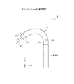
- the XYZ coordinates are fixed at the distal end of the flexible portion, that is, the proximal end of the bending portion 40 .
- the Z-axis is parallel to the axial direction NDr of the tip of the soft portion.
- the vertical direction of the curve is the curve around the X-axis
- the horizontal direction of the curve is the curve around the Y-axis.
- the angle formed by the axial direction NDr of the tip of the flexible portion and the imaging direction IDr is the bending angle ⁇ r.
- FIG. 3 shows the bending angle around the Y-axis, that is, in the left-right direction.
- the bending portion 40 is operated independently in the vertical direction and the horizontal direction, there are bending angles around the X-axis and bending angles around the Y-axis.
- the bending angle indicated by ⁇ r can be applied to both the bending operation around the X-axis and the Y-axis.
- the bending angle about the X axis is described as ⁇ x
- the bending angle about the Y axis is described as ⁇ y.
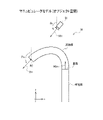
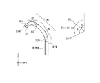
- FIG. 4 shows an explanatory diagram of the 3D model configured by the processing unit 210.
- the xyz coordinates are fixed in the object space in which the 3D model 50 is constructed.
- the xyz coordinates are also called world coordinates.
- a 3D model 50 of the endoscope is fixed in the object space so that NDm is parallel to the z-direction, where NDm is the axial direction of the distal end of the flexible portion.
- the fixed part is, for example, the base of the flexible part or the proximal end of the curved part.
- the 3D model 50 is, for example, a model composed of primitive surfaces such as polygons, or a wireframe model.
- the sensor 103 detects the bending angle ⁇ r of the endoscope 10 in real space, and the processing unit 210 constructs the 3D model 50 using the bending angle ⁇ r as the bending angle ⁇ m in the 3D model 50 .
- the processing unit 210 sets the line-of-sight direction SDc of the virtual camera 52 based on the bending angle ⁇ m, and sets the position and posture of the virtual camera 52 so that the line-of-sight direction SDc faces the point of gaze RC.
- the gaze point RC is set, for example, at the tip of the curved portion, but is not limited to this, and may be set within the curved portion, such as near the tip of the curved portion. Note that the processing unit 210 arranges the virtual camera 52 so as to look down on the gaze point RC from slightly above the 3D model 50 (+y direction).
- the processing unit 210 changes the line-of-sight direction SDc by changing the position and posture of the virtual camera 52 according to the bending angle ⁇ m.
- the line-of-sight direction SDc of the virtual camera 52 rotates about the gaze point RC.
- the gaze point RC is also referred to as the center of rotation of the line-of-sight direction SDc.
- the position and orientation of the virtual camera 52 are also referred to as a viewpoint, and changing the position and orientation of the virtual camera 52 according to the bending angle ⁇ m is also referred to as rotating the viewpoint.
- ⁇ c be the angle formed by the line-of-sight direction SDc of the virtual camera 52 and the axial direction NDm of the tip of the soft portion.
- the line-of-sight direction SDc is represented by this angle ⁇ c.
- the angle between the line-of-sight direction SDc and the axial direction NDm on the zx plane is ⁇ c. That is, the rotation angle of the line-of-sight direction SDc around the y-axis is ⁇ c.
- the rotation angle of the line-of-sight direction SDc around the x-axis is ⁇ c.
- the processing unit 210 controls the rotation angle of the line-of-sight direction SDc around the x-axis according to the bending angle ⁇ x around the x-axis, and controls the rotation angle of the line-of-sight direction SDc around the y-axis according to the bending angle ⁇ y around the y-axis. Control.
- the content shown with the angle ⁇ c can be applied to both rotation of the viewpoint around the x-axis and around the y-axis. When they are clearly distinguished and described, they are described as a rotation angle ⁇ cx about the x-axis and a rotation angle ⁇ cy about the y-axis.
- the processing unit 210 generates a CG image of the endoscope 3D model viewed from the virtual camera 52 and displays the CG image on the display 20 together with the endoscope image.
- the viewpoint of the virtual camera 52 changes according to the bending angle of the bending portion 40, and the imaging direction of the endoscopic image and the imaging direction of the 3D model can be substantially matched on the screen.
- the imaging direction in the endoscopic image and the imaging direction in the 3D model do not necessarily match, and are similar to the extent that the bending operation direction can be intuitively grasped. It is sufficient if it is in the direction.
- the processing unit 210 may display a CG image of the 3D model of the inside of the body together with the CG image of the 3D model of the endoscope.
- the in-vivo 3D model is constructed from, for example, tomographic images taken in advance by CT, MRI, etc., and constructed in the object space together with the endoscope 3D model.
- the image processing device 200 includes the acquisition unit 220 and the processing unit 210.
- Acquisition unit 220 acquires shape information about the shape of a manipulator whose shape is changeable.
- the processing unit 210 displays a CG image of the manipulator model viewed from the virtual camera 52 in the object space on the display 20 based on the shape information.
- the processing unit 210 performs rotation processing for rotating the line-of-sight direction SDc of the virtual camera 52 at a rotation angle ⁇ c corresponding to the shape.
- the imaging direction of the imaging unit installed on or held by the manipulator changes according to the shape of the manipulator.
- the imaging direction of the captured image and the imaging direction of the CG image of the manipulator model can be substantially matched on the screen.
- the manipulator includes a curved portion 40 .
- the acquisition unit 220 acquires information on the bending angle ⁇ r of the bending portion 40 as shape information.
- the processing unit 210 performs rotation processing to rotate the line-of-sight direction SDc of the virtual camera 52 by the rotation angle ⁇ c corresponding to the bending angle ⁇ r.
- the imaging direction IDr of the imaging section 30 installed at the tip of the bending section 40 changes according to the bending angle ⁇ r.
- the imaging direction IDr in the endoscope image and the imaging direction IDm in the CG image of the endoscope 3D model are substantially matched on the screen. be able to. This makes it easier for the operator to intuitively grasp the operation direction of the bending operation when viewing the 3D model.
- the rotation process is a process of rotating the line-of-sight direction SDc of the virtual camera 52 around the set point set on the manipulator model. More specifically, the rotation process is a rotation process around a rotation axis that passes through a set point and is parallel to the x axis in the case of rotation around the x axis, and passes through the set point in the case of rotation around the y axis. This is rotation processing about a rotation axis parallel to the y-axis.
- the gaze point RC corresponds to the set point.
- the gaze point RC may be set within the curved portion of the 3D model.
- the set point is not limited to the tip of the manipulator model, as long as it is set on the manipulator model.
- the set point may be set at an arbitrary position within the portion whose shape is changed by manipulation, or at the proximal end where the shape-changing portion is connected to the shape-not changing portion.
- the manipulator system includes a manipulator having an imaging unit at its tip, an image processing device 200, and a display 20.
- the image processing device 200 displays on the display 20 a CG image of the manipulator model in the line-of-sight direction SDc of the virtual camera 52 following the imaging direction IDr of the imaging unit.
- the line-of-sight direction SDc of the virtual camera 52 follows the imaging direction IDr so that the imaging direction of the CG image of the manipulator model substantially matches the imaging direction of the captured image. An image is displayed.
- the line-of-sight direction follows the imaging direction means that the line-of-sight direction changes in the same direction as the imaging direction changes, and the line-of-sight direction does not need to match the imaging direction.
- the line-of-sight direction does not always match the imaging direction, but such a case is also included in "following".
- FIG. 5 shows the relationship between the bending angle ⁇ m and the rotation angle ⁇ c of the line-of-sight direction SDc in the first embodiment.
- FIG. 6 shows a display example in the first embodiment.
- the counterclockwise rotation as viewed from the +y direction is defined as a positive angle
- the counterclockwise rotation as viewed from the +x direction is defined as a positive angle.
- left curvature and up curvature are positive angle curvatures.
- the definition of angle is not limited to this.
- the imaging direction IDm in the CG image always coincides with the imaging direction IDr in the endoscopic image because it is always in the depth direction of the screen.
- a display image IMB1 is a display example when the bending portion 40 is not bent
- a display image IMB2 is a display example when the bending portion 40 makes a J-turn to the left.
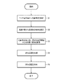
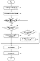
- FIG. 7 is a flowchart of processing in the first embodiment.
- the processing unit 210 estimates the bending angle ⁇ r of the endoscope 10 from the wire pulling amount detected by the sensor 103 .
- a model that associates the wire pulling amount with the bending angle ⁇ r is described using a formula, a lookup table, or the like, and the wire pulling amount is converted into the bending angle ⁇ r using the model.
- the control device 100 may perform the processing of step S1.
- the physical quantity for estimating the bending angle ⁇ r is not limited to the amount of wire pulling, and may be, for example, the amount of rotation of an operation knob, the amount of rotation of a motor, or the result of shape measurement by UPD.
- a virtual camera 52 is installed inside.
- step S4 the processing unit 210 generates a CG image of the endoscope 3D model viewed from the virtual camera 52.
- step S5 the processing unit 210 displays the generated CG image on the display 20 together with the endoscopic image.
- the processing unit 210 changes the rotation angle ⁇ c of the line-of-sight direction SDc in synchronization with the bending angle ⁇ r. Synchronizing the rotation angle ⁇ c with the bending angle ⁇ r means matching the rotation angle ⁇ c with changes in the bending angle ⁇ r in real time.
- the viewpoint of the virtual camera 52 is rotated so that the line-of-sight direction SDc is directed in the same direction as the bending angle ⁇ r. It is possible to match the imaging direction IDm in the CG image. As a result, regardless of the bending angle, the operating direction of the bending operation matches the moving direction of the tip of the bending portion in the 3D model, so that the operator can intuitively grasp the operating direction.
- FIG. 8 shows the relationship between the bending angle .theta.m and the rotation angle .theta.c of the line-of-sight direction SDc in the second embodiment.
- FIG. 9 shows a display example of a CG image in the second embodiment.
- the imaging direction changes between the depth direction and the horizontal direction of the screen, and does not face the front side of the horizontal direction of the screen.
- the difference between the imaging direction of the endoscopic image and the imaging direction of the CG image is 90 degrees or less, enabling an intuitive bending operation.
- FIG. 10 is a flowchart of processing in the second embodiment.
- the processing unit 210 estimates the bending angle ⁇ r of the endoscope 10 from the wire pulling amount detected by the sensor 103 .
- step S23 the processing unit 210 determines whether or not the bending angle around the x-axis satisfies
- step S25 the processing unit 210 determines whether or not the bending angle around the y-axis satisfies
- step S27 the processing unit 210 generates a CG image of the endoscope 3D model viewed from the virtual camera 52.
- step S28 the processing unit 210 displays the generated CG image on the display 20 together with the endoscopic image.
- the viewpoint is switched only once, but the viewpoint may be switched multiple times.
- the processing unit 210 fixes the rotation angle ⁇ c to the first angle until the bending angle ⁇ r exceeds the threshold value ⁇ .
- the first angle is 0 degrees, but is not limited to this.
- the processing unit 210 switches the rotation angle ⁇ c to a second angle ⁇ that is larger than the first angle.
- the viewpoint is switched when the bending angle ⁇ r exceeds a predetermined angle. can be made close to the imaging direction IDm in . Since the viewpoint does not rotate frequently, it can be expected that the curved shape can be easily recognized visually from the CG image.
- FIG. 11 shows the relationship between the bending angle ⁇ m and the rotation angle ⁇ c of the line-of-sight direction SDc in the third embodiment.
- FIG. 12 shows a display example of a CG image in the third embodiment.
- ⁇ 2 degrees. and set ⁇ c ⁇ degrees in the range of ⁇ 2 degrees ⁇
- the difference between the imaging direction of the endoscopic image and the imaging direction of the CG image is 75 degrees or less, enabling an intuitive bending operation.
- the viewpoint of the virtual camera has been intentionally changed and the meaning of the viewpoint switching, it is easy for the operator to understand the bending state and the bending operation direction when viewing the CG image.
- FIG. 13 is a flowchart of processing in the third embodiment.
- the processing unit 210 estimates the bending angle ⁇ r of the endoscope 10 from the wire pulling amount detected by the sensor 103 .
- step S43 the processing unit 210 determines whether or not the bending angle around the x-axis satisfies
- ⁇ 2, and ⁇ 1 when ⁇ 2 ⁇
- . In step S45, the processing unit 210 rotates the viewpoint of the virtual camera 52 by ⁇ cx ⁇ degrees about the x-axis around the point of gaze RC. Next, the process proceeds to step S46.
- step S46 the processing unit 210 determines whether or not the bending angle around the y-axis satisfies
- ⁇ 1, the processor 210 calculates the transition rate ⁇ in step S47. In step S45, the processing unit 210 rotates the viewpoint of the virtual camera 52 by ⁇ cy ⁇ degrees about the x-axis around the point of gaze RC. Next, the process proceeds to step S49.
- step S49 the processing unit 210 generates a CG image of the endoscope 3D model viewed from the virtual camera 52.
- step S50 the processing unit 210 displays the generated CG image on the display 20 together with the endoscopic image.
- the processing unit 210 fixes the rotation angle ⁇ c to the first fixed angle when the bending angle ⁇ r is smaller than the first threshold value ⁇ 1.
- the first fixed angle is 0 degrees, but is not limited to this.
- the processing unit 210 changes the rotation angle ⁇ c from the first fixed angle to the second threshold value ⁇ 2 according to the bending angle ⁇ r. It is changed to a second fixed angle ⁇ that is greater than one fixed angle.
- the processing unit 210 fixes the rotation angle ⁇ c to the second fixed angle ⁇ when the bending angle ⁇ r is greater than the second threshold value ⁇ 2.
- the difference between the imaging direction of the endoscopic image and the imaging direction of the CG image can be reduced compared to the case where the viewpoint is not rotated, so an intuitive bending operation is possible.
- an effect is obtained that makes it possible to understand that the viewpoint of the virtual camera has been intentionally changed and the meaning of the viewpoint switching, it is easy for the operator to understand the bending state and the bending operation direction when viewing the CG image.
- the operation unit 400 is configured to allow operation input for switching between the fixed mode and the rotating mode.
- the processing unit 210 sets the fixed mode or the rotation mode according to the input.
- the processing unit 210 can switch between a rotation mode in which rotation processing is performed to rotate the line-of-sight direction SDc of the virtual camera 52 and a fixed mode in which the rotation angle ⁇ c is fixed regardless of the shape of the manipulator. .
- this embodiment it is possible to switch between rotation mode and fixed mode depending on the operator. As a result, it can be used by both an operator who can easily grasp the bending operation state and the operation direction when the viewpoint is fixed, and an operator who can easily grasp the bending operation state and the operation direction when the viewpoint is rotated. It is possible.
- FIG. 14 is a flow chart when the fifth embodiment is combined with the second embodiment.
- the processing unit 210 estimates the bending angle ⁇ r of the endoscope 10 from the amount of wire traction detected by the sensor 103 .
- step S63 the processing unit 210 determines whether or not the bending angle about the x-axis is greater than or equal to the bending angle about the x-axis, that is, whether
- step S63 the processing unit 210 determines whether the bending angle around the y-axis satisfies
- step S68 the processing unit 210 generates a CG image of the endoscope 3D model viewed from the virtual camera 52.
- step S69 the processing unit 210 displays the generated CG image on the display 20 together with the endoscopic image.
- FIG. 15 is a flow chart when the fifth embodiment is combined with the third embodiment.
- the processing unit 210 estimates the bending angle ⁇ r of the endoscope 10 from the amount of wire traction detected by the sensor 103 .
- step S83 the processing unit 210 determines whether or not the bending angle about the x-axis is greater than or equal to the bending angle about the x-axis, that is, whether
- ⁇ 1, the processor 210 calculates the transition rate ⁇ in step S85. In step S86, the processing unit 210 rotates the viewpoint of the virtual camera 52 by ⁇ cx ⁇ degrees about the x-axis around the point of gaze RC. Then, the process proceeds to step S90.
- step S83 the processing unit 210 determines whether the bending angle around the y-axis satisfies
- ⁇ 1, the processing unit 210 calculates the transition rate ⁇ in step S88. In step S89, the processing unit 210 rotates the viewpoint of the virtual camera 52 by ⁇ cy ⁇ degrees about the x-axis around the point of gaze RC. Then, the process proceeds to step S90.
- step S90 the processing unit 210 generates a CG image of the endoscope 3D model viewed from the virtual camera 52.
- step S91 the processing unit 210 displays the generated CG image on the display 20 together with the endoscopic image.
- the acquisition unit 220 acquires information on the first bending angle ⁇ x about the first axis and the second bending angle ⁇ y about the second axis that intersects the first axis.
- the x-axis corresponds to the first axis and the y-axis corresponds to the second axis.
- the processing unit 210 performs rotation processing at a rotation angle ⁇ c corresponding to the larger one of the first bending angle ⁇ x and the second bending angle ⁇ y.
- the viewpoint of the virtual camera 52 rotates only around the x-axis or around the y-axis, so the viewpoint rotation in the CG image is simplified compared to the case where the viewpoint rotates around both axes. be done. As a result, it can be expected that the curved shape can be easily recognized visually from the CG image.
- FIG. 16 shows a configuration example of a bending portion in a sixth embodiment.
- Bending portion 40 includes a first bending portion 41 and a second bending portion 42 .
- the first bending portion 41 is also called a distal bending portion
- the second bending portion 42 is also called a proximal bending portion.
- the proximal end of the second bending portion 42 is the proximal end of the bending portion 40 and is connected to the distal end of the flexible portion.
- the proximal end of the first bending portion 41 is connected to the distal end of the second bending portion 42 , and the hard portion and the imaging portion 30 are provided at the distal end of the first bending portion 41 .
- an electric endoscope is assumed, and the first bending section 41 and the second bending section 42 are controlled according to modes described later with reference to FIG. Depending on the mode, the first bending section 41 and the second bending section 42 may be controlled independently or cooperatively.
- the axial direction of the tip of the flexible portion is NDm
- the axial direction of the tip of the second bending portion 42 is ID2
- the axial direction of the tip of the first bending portion 41 is ID1.
- the angle formed by ID1 and ID2 is the bending angle ⁇ 1 of the first bending portion 41
- the angle formed by ID2 and NDm is the bending angle ⁇ 2 of the second bending portion 42 .
- FIG. 17 shows an example of a two-step curving control mode.
- the control device 100 has a distal bending mode, a proximal bending mode, a pseudo one-step mode, and a parallel mode as two-step bending control modes.
- the operation unit 400 is configured to be able to accept a mode switching operation and a bending operation in each mode.
- the control device 100 also includes a first motor that bends the first bending portion 41 and a second motor that bends the second bending portion 42 . By controlling , the first bending portion 41 and the second bending portion 42 are driven to bend.
- the processing unit 210 switches viewpoint control of the virtual camera 52 according to the mode set by the operation unit 400 .
- the bending angle ⁇ 2 of the second bending portion 42 is fixed, and the bending angle ⁇ 1 of the first bending portion 41 is variably controlled according to the operation input.
- the bending angle ⁇ 1 of the first bending portion 41 is fixed, and the bending angle ⁇ 2 of the second bending portion 42 is variably controlled according to the operation input.
- the gaze point RC may be located within the second curved portion 42 , for example, near the tip of the second curved portion 42 .
- the first bending section 41 and the second bending section 42 are controlled so that the imaging direction moves in parallel.
- ⁇ 2 is controlled in the + direction and ⁇ 1 is controlled in the - direction.
- the gaze point RC may be within the first bending portion 41 , for example, near the tip of the first bending portion 41 .
- the bending portion 40 includes the first bending portion 41 and the second bending portion 42 provided on the proximal side of the first bending portion 41 .
- the processing unit 210 performs the rotation process at a rotation angle ⁇ c corresponding to the second bending portion bending angle ⁇ 2, which is the bending angle of the second bending portion 42, or the overall bending angle ⁇ A, which is the bending angle of the bending portion 40 as a whole. conduct.
- the viewpoint of the virtual camera 52 can follow the imaging direction according to the bending state. This makes it possible to intuitively grasp the bending operation direction even in two-step bending.
- the processing unit 210 performs the rotation processing at the rotation angle ⁇ c corresponding to the second bending portion bending angle ⁇ 2. Specifically, this rotation processing is performed in a distal bending mode and a proximal bending mode in which the first bending portion 41 and the second bending portion 42 are individually controlled.
- the processing portion 210 rotates according to the overall bending angle ⁇ A. Rotation processing is performed at an angle ⁇ c. Specifically, this rotation processing is performed in the pseudo one-step mode and the parallel mode in which the first bending section 41 and the second bending section 42 are controlled cooperatively.
- the processing unit 210 performs rotation processing at the rotation angle ⁇ c corresponding to the second bending portion bending angle ⁇ 2 when the second bending portion 42 is in the first bending mode in which bending is controlled.
- the processing section 210 is controlled in a second bending mode in which the bending direction of the first bending portion 41 is controlled in the same direction as the bending direction of the second bending portion 42, or in a second bending mode in which the bending direction of the first bending portion 41 is controlled in the second bending mode.
- the rotation processing is performed at the rotation angle ⁇ c corresponding to the overall bending angle ⁇ A.
- the proximal bending mode corresponds to the first bending mode
- the pseudo one-step mode corresponds to the second bending mode
- the parallel mode corresponds to the third bending mode.
Landscapes
- Engineering & Computer Science (AREA)
- Health & Medical Sciences (AREA)
- Life Sciences & Earth Sciences (AREA)
- Surgery (AREA)
- Physics & Mathematics (AREA)
- Public Health (AREA)
- Animal Behavior & Ethology (AREA)
- General Health & Medical Sciences (AREA)
- Biomedical Technology (AREA)
- Nuclear Medicine, Radiotherapy & Molecular Imaging (AREA)
- Molecular Biology (AREA)
- Medical Informatics (AREA)
- Heart & Thoracic Surgery (AREA)
- Veterinary Medicine (AREA)
- Biophysics (AREA)
- Radiology & Medical Imaging (AREA)
- Pathology (AREA)
- Optics & Photonics (AREA)
- Theoretical Computer Science (AREA)
- General Physics & Mathematics (AREA)
- Computer Graphics (AREA)
- Computer Hardware Design (AREA)
- General Engineering & Computer Science (AREA)
- Software Systems (AREA)
- Robotics (AREA)
- Signal Processing (AREA)
- Geometry (AREA)
- Architecture (AREA)
- Human Computer Interaction (AREA)
- Mechanical Engineering (AREA)
- Instruments For Viewing The Inside Of Hollow Bodies (AREA)
- Endoscopes (AREA)
Priority Applications (3)
| Application Number | Priority Date | Filing Date | Title |
|---|---|---|---|
| JP2023529259A JP7653518B2 (ja) | 2021-06-22 | 2021-06-22 | 画像処理装置、マニピュレータシステム及び画像処理装置の作動方法 |
| PCT/JP2021/023516 WO2022269736A1 (ja) | 2021-06-22 | 2021-06-22 | 画像処理装置、マニピュレータシステム、画像処理方法及び表示方法 |
| US18/385,552 US12475664B2 (en) | 2021-06-22 | 2023-10-31 | Image processing device, manipulator system, image processing method and display method |
Applications Claiming Priority (1)
| Application Number | Priority Date | Filing Date | Title |
|---|---|---|---|
| PCT/JP2021/023516 WO2022269736A1 (ja) | 2021-06-22 | 2021-06-22 | 画像処理装置、マニピュレータシステム、画像処理方法及び表示方法 |
Related Child Applications (1)
| Application Number | Title | Priority Date | Filing Date |
|---|---|---|---|
| US18/385,552 Continuation US12475664B2 (en) | 2021-06-22 | 2023-10-31 | Image processing device, manipulator system, image processing method and display method |
Publications (1)
| Publication Number | Publication Date |
|---|---|
| WO2022269736A1 true WO2022269736A1 (ja) | 2022-12-29 |
Family
ID=84545285
Family Applications (1)
| Application Number | Title | Priority Date | Filing Date |
|---|---|---|---|
| PCT/JP2021/023516 Ceased WO2022269736A1 (ja) | 2021-06-22 | 2021-06-22 | 画像処理装置、マニピュレータシステム、画像処理方法及び表示方法 |
Country Status (3)
| Country | Link |
|---|---|
| US (1) | US12475664B2 (https=) |
| JP (1) | JP7653518B2 (https=) |
| WO (1) | WO2022269736A1 (https=) |
Citations (4)
| Publication number | Priority date | Publication date | Assignee | Title |
|---|---|---|---|---|
| JP2004180940A (ja) * | 2002-12-03 | 2004-07-02 | Olympus Corp | 内視鏡装置 |
| WO2005039401A1 (ja) * | 2003-10-29 | 2005-05-06 | Olympus Corporation | 挿入支援システム |
| JP2009056238A (ja) * | 2007-09-03 | 2009-03-19 | Olympus Medical Systems Corp | 内視鏡装置 |
| WO2021054360A1 (ja) * | 2019-09-20 | 2021-03-25 | Hoya株式会社 | 内視鏡用プロセッサ、プログラム、情報処理方法及び情報処理装置 |
Family Cites Families (7)
| Publication number | Priority date | Publication date | Assignee | Title |
|---|---|---|---|---|
| JP4728456B1 (ja) * | 2010-02-22 | 2011-07-20 | オリンパスメディカルシステムズ株式会社 | 医療機器 |
| US9770216B2 (en) | 2014-07-02 | 2017-09-26 | Covidien Lp | System and method for navigating within the lung |
| CN108778113B (zh) | 2015-09-18 | 2022-04-15 | 奥瑞斯健康公司 | 管状网络的导航 |
| JP2017205292A (ja) | 2016-05-18 | 2017-11-24 | オリンパス株式会社 | 画像ファイル作成方法、画像ファイル作成プログラム及び画像ファイル作成装置 |
| WO2020123671A1 (en) * | 2018-12-11 | 2020-06-18 | Project Moray, Inc. | Hybrid-dimensional, augmented reality, and/or registration of user interface and simulation systems for robotic catheters and other uses |
| EP4635444A3 (en) * | 2020-03-24 | 2025-12-31 | Intuitive Surgical Operations, Inc. | Systems and methods for registering an instrument to an image using point cloud data and endoscopic image data |
| WO2021257897A1 (en) * | 2020-06-17 | 2021-12-23 | Project Moray, Inc. | Axial insertion and movement along a partially constrained path for robotic catheters and other uses |
-
2021
- 2021-06-22 WO PCT/JP2021/023516 patent/WO2022269736A1/ja not_active Ceased
- 2021-06-22 JP JP2023529259A patent/JP7653518B2/ja active Active
-
2023
- 2023-10-31 US US18/385,552 patent/US12475664B2/en active Active
Patent Citations (4)
| Publication number | Priority date | Publication date | Assignee | Title |
|---|---|---|---|---|
| JP2004180940A (ja) * | 2002-12-03 | 2004-07-02 | Olympus Corp | 内視鏡装置 |
| WO2005039401A1 (ja) * | 2003-10-29 | 2005-05-06 | Olympus Corporation | 挿入支援システム |
| JP2009056238A (ja) * | 2007-09-03 | 2009-03-19 | Olympus Medical Systems Corp | 内視鏡装置 |
| WO2021054360A1 (ja) * | 2019-09-20 | 2021-03-25 | Hoya株式会社 | 内視鏡用プロセッサ、プログラム、情報処理方法及び情報処理装置 |
Also Published As
| Publication number | Publication date |
|---|---|
| US12475664B2 (en) | 2025-11-18 |
| JPWO2022269736A1 (https=) | 2022-12-29 |
| JP7653518B2 (ja) | 2025-03-28 |
| US20240062499A1 (en) | 2024-02-22 |
Similar Documents
| Publication | Publication Date | Title |
|---|---|---|
| JP7756079B2 (ja) | 外科手術仮想現実ユーザインターフェース | |
| JP5737796B2 (ja) | 内視鏡操作システムおよび内視鏡操作プログラム | |
| CN109806002B (zh) | 一种手术机器人 | |
| KR102358967B1 (ko) | 이미징 기기의 방향 제어 시스템 및 방법 | |
| KR101407986B1 (ko) | 3차원 텔레스트레이션을 제공하는 의료용 로봇 시스템 | |
| KR101705921B1 (ko) | 수술 로봇의 통합적 표현 | |
| US20140114481A1 (en) | Medical master slave manipulator system | |
| JP5766150B2 (ja) | 内視鏡操作システム | |
| JPWO2018159338A1 (ja) | 医療用支持アームシステムおよび制御装置 | |
| CN101530326A (zh) | 胶囊引导系统 | |
| CN118043005A (zh) | 用于控制内部体腔中的手术机器人组件的系统和方法 | |
| JP3482228B2 (ja) | 視線検出によるマニピュレータ制御システム | |
| US20250134610A1 (en) | Systems and methods for remote mentoring in a robot assisted medical system | |
| JP2007034628A (ja) | 画像処理方法及び装置 | |
| JP7653518B2 (ja) | 画像処理装置、マニピュレータシステム及び画像処理装置の作動方法 | |
| CN119279792B (zh) | 内窥镜运动控制方法及手术机器人 | |
| JP5800609B2 (ja) | 医療用マスタスレーブマニピュレータ | |
| WO2015133608A1 (ja) | 手術支援システムおよびこれに用いるカメラユニット | |
| CN115192207B (zh) | 手术机器人、主操作台及其控制方法、控制装置 | |
| WO2022230160A1 (ja) | 内視鏡システム、内腔構造算出システム及び内腔構造情報の作成方法 | |
| WO2025230949A1 (en) | Systems and methods for adapting depth placement of graphical user interface elements with surgical imagery | |
| WO2026083234A1 (en) | Method and system for constraint-aware inverse kinematics with trajectory planning for a surgical robot | |
| JP2026500177A (ja) | 生体構造セグメンテーション及び解剖学的構造追跡のためのシステム及び方法 | |
| JP2026510579A (ja) | 外科手術ツールと連携した操作のためのカメラ装置 | |
| JP2020151467A (ja) | 内視鏡プロセッサおよび内視鏡システム |
Legal Events
| Date | Code | Title | Description |
|---|---|---|---|
| 121 | Ep: the epo has been informed by wipo that ep was designated in this application |
Ref document number: 21947024 Country of ref document: EP Kind code of ref document: A1 |
|
| WWE | Wipo information: entry into national phase |
Ref document number: 2023529259 Country of ref document: JP |
|
| NENP | Non-entry into the national phase |
Ref country code: DE |
|
| 122 | Ep: pct application non-entry in european phase |
Ref document number: 21947024 Country of ref document: EP Kind code of ref document: A1 |