WO2022264819A1 - 点灯制御装置、点灯制御方法、照明装置 - Google Patents
点灯制御装置、点灯制御方法、照明装置 Download PDFInfo
- Publication number
- WO2022264819A1 WO2022264819A1 PCT/JP2022/022425 JP2022022425W WO2022264819A1 WO 2022264819 A1 WO2022264819 A1 WO 2022264819A1 JP 2022022425 W JP2022022425 W JP 2022022425W WO 2022264819 A1 WO2022264819 A1 WO 2022264819A1
- Authority
- WO
- WIPO (PCT)
- Prior art keywords
- light source
- source units
- time
- lighting control
- switch element
- Prior art date
- Legal status (The legal status is an assumption and is not a legal conclusion. Google has not performed a legal analysis and makes no representation as to the accuracy of the status listed.)
- Ceased
Links
Images


Classifications
-
- H—ELECTRICITY
- H05—ELECTRIC TECHNIQUES NOT OTHERWISE PROVIDED FOR
- H05B—ELECTRIC HEATING; ELECTRIC LIGHT SOURCES NOT OTHERWISE PROVIDED FOR; CIRCUIT ARRANGEMENTS FOR ELECTRIC LIGHT SOURCES, IN GENERAL
- H05B45/00—Circuit arrangements for operating light-emitting diodes [LED]
- H05B45/30—Driver circuits
- H05B45/34—Voltage stabilisation; Maintaining constant voltage
-
- H—ELECTRICITY
- H05—ELECTRIC TECHNIQUES NOT OTHERWISE PROVIDED FOR
- H05B—ELECTRIC HEATING; ELECTRIC LIGHT SOURCES NOT OTHERWISE PROVIDED FOR; CIRCUIT ARRANGEMENTS FOR ELECTRIC LIGHT SOURCES, IN GENERAL
- H05B47/00—Circuit arrangements for operating light sources in general, i.e. where the type of light source is not relevant
- H05B47/10—Controlling the light source
- H05B47/16—Controlling the light source by timing means
-
- H—ELECTRICITY
- H05—ELECTRIC TECHNIQUES NOT OTHERWISE PROVIDED FOR
- H05B—ELECTRIC HEATING; ELECTRIC LIGHT SOURCES NOT OTHERWISE PROVIDED FOR; CIRCUIT ARRANGEMENTS FOR ELECTRIC LIGHT SOURCES, IN GENERAL
- H05B45/00—Circuit arrangements for operating light-emitting diodes [LED]
- H05B45/30—Driver circuits
- H05B45/37—Converter circuits
-
- H—ELECTRICITY
- H05—ELECTRIC TECHNIQUES NOT OTHERWISE PROVIDED FOR
- H05B—ELECTRIC HEATING; ELECTRIC LIGHT SOURCES NOT OTHERWISE PROVIDED FOR; CIRCUIT ARRANGEMENTS FOR ELECTRIC LIGHT SOURCES, IN GENERAL
- H05B45/00—Circuit arrangements for operating light-emitting diodes [LED]
- H05B45/40—Details of LED load circuits
- H05B45/44—Details of LED load circuits with an active control inside an LED matrix
- H05B45/46—Details of LED load circuits with an active control inside an LED matrix having LEDs disposed in parallel lines
-
- Y—GENERAL TAGGING OF NEW TECHNOLOGICAL DEVELOPMENTS; GENERAL TAGGING OF CROSS-SECTIONAL TECHNOLOGIES SPANNING OVER SEVERAL SECTIONS OF THE IPC; TECHNICAL SUBJECTS COVERED BY FORMER USPC CROSS-REFERENCE ART COLLECTIONS [XRACs] AND DIGESTS
- Y02—TECHNOLOGIES OR APPLICATIONS FOR MITIGATION OR ADAPTATION AGAINST CLIMATE CHANGE
- Y02B—CLIMATE CHANGE MITIGATION TECHNOLOGIES RELATED TO BUILDINGS, e.g. HOUSING, HOUSE APPLIANCES OR RELATED END-USER APPLICATIONS
- Y02B20/00—Energy efficient lighting technologies, e.g. halogen lamps or gas discharge lamps
- Y02B20/40—Control techniques providing energy savings, e.g. smart controller or presence detection
Definitions
- the present disclosure relates to a lighting control device, a lighting control method, and a lighting device.
- Patent Document 1 describes a lighting device configured to connect serial circuits each including an LED and a switch in parallel and to supply power to them from a DC-DC converter. It is In this lighting device, each LED can be turned on and off individually by opening and closing each switch independently.
- One of the purposes of the specific aspect of the present disclosure is to make the conduction time of the light emitting element more uniform.
- a lighting control device is a device that drives a plurality of light source units that are connected in parallel with each other in a time-sharing manner, comprising: (a) being connected to the plurality of light source units and (b) a plurality of switch elements connected in series to each of the plurality of light source units; and (c) a current between the power supply circuit and the plurality of light source units. (d) the signal output from the current detection unit; (e) the controller, after controlling one of the plurality of switch elements to a closed state, the The lighting control device starts timing of a specified time when the signal from the current detection unit becomes the first state, and controls the one switch element to open when the specified time elapses.
- a lighting control method is a method of driving a plurality of light source units connected in parallel with each other in a time division manner using a controller, wherein (a) the controller (b) (c) current flowing through a current path between a power supply circuit and the plurality of light source units; (d) controlling the one switch element to open when the specified time elapses.
- a lighting device is a lighting device including the lighting control device of [1] and a plurality of light source units connected to the lighting control device.
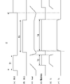
- FIG. 1 is a diagram showing the configuration of a lighting control device according to one embodiment.
- FIG. 2 is a diagram showing a configuration example of a microcomputer that implements the controller.
- 3A to 3F are waveform diagrams for explaining the basic operation of the lighting control device.
- FIG. 4 is a flow chart showing operation procedures in the controller.
- 5A to 5D are waveform diagrams for explaining the operation of the lighting control device.
- 6A to 6D are waveform diagrams for explaining the operation of the lighting control device of the comparative example.
- FIG. 1 is a diagram showing the configuration of a lighting control device according to one embodiment.
- the illustrated lighting control device 1 receives electric power from a battery 4 mounted on a vehicle, and controls lighting and extinguishing of lamp units 2 and 3, each of which includes a plurality of light emitting elements (LEDs). .
- the lighting control device 1 includes a DC-DC converter 10 , a controller 11 , switch elements 12 and 13 , a resistance element 14 and a capacitance element 15 .
- the lighting control device 1 and lamp units (light source units) 2 and 3 constitute a vehicle lamp (lighting device).
- the lamp unit 2 is configured by connecting a plurality of (eight in the illustrated example) light emitting elements in series, one end of which is connected to the switch element 12, and the other end of which is connected to a GND terminal (reference potential terminal).
- the lamp unit 3 is configured by connecting a smaller number of light emitting elements (five in the illustrated example) in series than the lamp unit 2. One end is connected to the switch element 13, and the other end is connected to a GND terminal (reference potential). terminal).
- the lamp unit 2 is used as a position lamp that indicates the width of the vehicle
- the lamp unit 3 is used as a headlamp that irradiates a low beam forward of the vehicle.
- the DC-DC converter 10 receives power from the battery 4 and generates and outputs a voltage for current flow to the lamp units 2 and 3 .
- the DC-DC converter 10 of the present embodiment converts each lamp unit 2, 3 based on the voltage across the resistance element 14 connected on the current path between each lamp unit 2, 3 and the DC-DC converter 10.
- a current detection unit 16 is provided to detect the flowing current (hereinafter referred to as “LED current”).
- the current detection unit 16 outputs a signal that becomes high level (first state) when the LED current exceeds a predetermined threshold value (for example, 50% of the specified value) and becomes low level (second state) when the LED current becomes smaller than the threshold value.
- a predetermined threshold value for example, 50% of the specified value
- second state low level
- the switch element 12 has one end connected to the DC-DC converter 10 via the resistance element 14 and the other end connected to the lamp unit 2 .
- the switch element 13 has one end connected to the DC-DC converter 10 via the resistance element 14 and the other end connected to the lamp unit 3 .
- These switch elements 12 and 13 receive a control signal from the controller 11 and are switched between an on/off state (open/closed state).
- a field effect transistor or a bipolar transistor can be used as the switch elements 12 and 13, for example.
- the resistor element 14 has one end connected to the DC-DC converter 10 and the other end connected to the switch elements 12 and 13 .
- One end of the capacitive element 15 is connected between the resistance element 14 and the switch elements 12 and 13, and the other end is connected to the GND terminal.
- the capacitive element 15 has roles such as stabilization of the output voltage of the DC-DC converter 10 and noise absorption.
- the controller 11 is connected to the switch elements 12 and 13 as well as to the DC-DC converter 10, and controls the overall operation of the lighting control device 1.
- the controller 11 is realized by executing a predetermined program in the CPU using a microcomputer (see FIG. 2, which will be described later) including, for example, a CPU, a ROM, a RAM, and the like.
- a microcomputer see FIG. 2, which will be described later
- the controller 11 includes an edge detection unit 21, a measurement unit 22, a timer unit 23, a correction value calculation unit 24, a switch control unit 25, and a control signal output unit 26 as functional blocks.
- the edge detection section 21 detects a high-level edge of the signal output from the current detection section 16 of the DC-DC converter 10, that is, a rising edge at which the signal changes from low level to high level.
- the measurement unit 22 measures the time from when the signal output from the current detection unit 16 of the DC-DC converter 10 becomes high level to when it changes to low level, that is, the time during which the high level is maintained.
- the timer unit 23 starts a timer operation (timekeeping operation) in response to the detection of the rising edge by the edge detection unit 21, and measures a preset prescribed time.
- the correction value calculating unit 24 calculates a correction value for correcting the specified time that should be measured by the timer unit 23 during timer operation.
- the switch control unit 25 outputs control signals to the switch elements 12 and 13 for controlling the ON/OFF operations of the switch elements 12 and 13 .
- the switch control unit 25 of the present embodiment switches the switch elements 12 and 13 from the ON state (closed state) to the OFF state (open state) in response to the elapse of a predetermined time after the timer operation by the timer unit 23 is completed. Outputs a control signal for
- the control signal output unit 26 outputs a control signal for switching execution/stop of the voltage output operation by the DC-DC converter 10 .
- the control signal output unit 26 outputs a control signal for stopping the DC-DC converter 10 (a state in which no voltage is output) in response to the elapse of the specified time due to the timer operation by the timer unit 23. to output
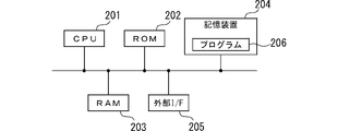
- FIG. 2 is a diagram showing a configuration example of a microcomputer that implements the controller.
- the illustrated microcomputer includes a CPU (Central Processing Unit) 201, a ROM (Read Only Memory) 202, a RAM (Random Access Memory) 203, a storage device 204, an external interface (I/F) 205, which are connected so as to be able to communicate with each other.
- the CPU 201 operates based on a basic control program read out from the ROM 202, reads out a program (application program) 206 stored in the storage device 204, and executes it to implement each function of the controller 11 described above.
- a RAM 203 temporarily stores data to be used when the CPU 201 operates.
- the storage device 204 is a nonvolatile storage device such as a hard disk or solid state drive, and stores various data such as the program 206 .
- An external interface 205 is an interface that connects the CPU 201 and an external device.
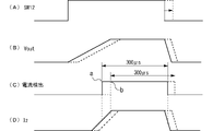
- FIG. 3(A) to 3(F) are waveform diagrams for explaining the basic operation of the lighting control device 1.
- FIG. power is supplied to the lamp units 2 and 3 in a time-division manner during one cycle T of control by the lighting control device 1, and the lamp units 2 and 3 are lit in a time-division manner.
- the lamp units 2 and 3 are perceived as continuously lighting from the outside.
- the switch element 12 (denoted as “SW12" in the drawing) is controlled to be in the ON state at the beginning of the period T1 within the period T, and at the end of the period T1 Switch element 12 is controlled to be in an off state.
- the drive voltage V out from the DC-DC converter 10 rises from 0 volts to a predetermined value in conjunction with switching to the ON state of the switch element 12, and remains at a constant value. After that, the drive voltage V out drops to 0 volts as the switch element 12 is switched to the off state.
- the LED current I2 flowing through the lamp unit 2 begins to increase when the drive voltage Vout exceeds the total value of the forward voltages VF of the light emitting elements of the lamp unit 2. It starts, rises to a predetermined value, then becomes constant, then decreases as the drive voltage Vout decreases, and becomes 0 amperes when it becomes equal to or less than the total value of the forward voltage VF.
- the signal output from the current detection unit 16 indicates that the LED current I2 is 50% or more based on the rated value (the constant value after the increase shown in the figure). It changes to a high level when it reaches a magnitude, and changes to a low level when it falls below 50%.
- the on/off state of the switch element 12 is controlled so that the period T2 during which the signal output from the current detection unit 16 maintains the high level is a predetermined specified time (target time: 300 ⁇ s as an example). be. The details of this control will be described later.
- the lighting control of the lamp unit 3 is the same as that of the lamp unit 2 described above. Specifically, as shown in FIG. 3B, the switch element 13 (denoted as “SW13” in the drawing) is turned on at the start of a period T3 starting from the start point after a certain period from the end point of the period T1. The switch element 13 is controlled to be in the ON state, and the switch element 13 is controlled to be in the OFF state at the end of the period T3.
- SW13 the switch element 13
- the drive voltage V out from the DC-DC converter 10 rises from 0 volts to a predetermined value in conjunction with switching to the ON state of the switch element 13, and remains at a constant value. After that, the drive voltage V out drops to 0 volts in accordance with the switching of the switch element 13 to the off state.
- the LED current I3 flowing through the lamp unit 3 begins to increase when the driving voltage Vout exceeds the total value of the forward voltages VF of the light emitting elements of the lamp unit 3. It starts, rises to a predetermined value, then becomes constant, then decreases as the drive voltage Vout decreases, and becomes 0 amperes when it becomes equal to or less than the total value of the forward voltage VF.
- the signal output from the current detection unit 16 indicates that the LED current I3 is 50% or more based on the rated value (constant value after the increase shown in the figure). It changes to a high level when it reaches a magnitude, and changes to a low level when it falls below 50%.
- the on/off state of the switch element 13 is controlled so that the period T4 during which the signal output from the current detector 16 maintains a high level becomes a predetermined constant value (target time: 3000 ⁇ s as an example). be. Details of this control will be described below.
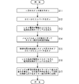
- the switch control unit 25 of the controller 11 turns on one switch element (here, the switch element 12) (step S11). Further, the control signal output unit 26 of the controller 11 turns on the DC-DC converter 10 (state of outputting voltage) (step S12).
- the switch element 12 is turned on as shown in FIG. 5A, and the lamp unit 2 and the DC-DC converter 10 are electrically connected. Then, as indicated by the solid line in FIG. 5B, the drive voltage V out output from the DC-DC converter 10 starts to rise.
- the current detection unit 16 turns off as indicated by the solid line in FIG. A high level signal is output (step S13).
- the edge detector 21 detects a high-level edge, and upon detection of this high-level edge, the timer 23 starts the clocking operation (step S14).
- the switch control unit 25 turns off the switch element 12 (step S15).
- the current detector 16 When the LED current becomes lower than the threshold, the current detector 16 outputs a low level signal (step S16).
- the measurement unit 22 measures the period during which the signal output from the current detection unit 16 maintains a high level.
- the correction value calculation unit 24 calculates the difference between the measured value of the high level period measured by the measurement unit 22 and the target value, and stores the difference in the memory as the correction value (step S17).
- the correction value obtained in step S17 is reflected in the timing of the timer unit in the next period. For example, if the specified time of the high level period is 300 ⁇ s and the measured value is 305 ⁇ s, the correction value obtained from the difference between them is ⁇ 5 ⁇ s. In the next cycle, the timer unit 23 sets the prescribed time to 295 ⁇ s reflecting this correction value and performs timekeeping.
- step S11 the process returns to step S11, and the same processing of steps S11 to S17 as described above is performed on the series circuit portion of the lamp unit 3 and the switch element 13. Control in one period T is now completed. After that, the process returns to step S11, and the same processing of steps S11 to S17 for the series circuit portion of the lamp unit 2 and the switch element 12 and steps S11 to S17 for the series circuit portion of the lamp unit 3 and the switch element 13 are performed. Each treatment is alternately performed.
- FIG. 1 the two lamp units 2 and 3 having different numbers of light-emitting elements are driven in a time division manner, so the driving voltage output from the DC-DC converter 10 varies for each lamp unit.
- the DC-DC converter 10 the input voltage from the battery 4 and the DC-DC converter 10 In a region where the output voltages of the DC-DC converters 10 are almost equal, topology switching between boosting and buck-boost occurs frequently in the DC-DC converter 10 .
- the start point of the LED current I2 is also delayed.
- the timing at which the signal output from the current detection unit 16 goes high is also delayed from the originally expected point a to point b.
- a high-level edge at the point b is detected by the edge detection section 21, the switch control section 25 turns on the switch element 12 accordingly, and the timer section 23 starts the timekeeping operation.
- a specified time eg, 300 ⁇ s
- the signal of the current detection unit 16 maintains a high level. Since the correction value is calculated based on the period during which the signal is applied and is reflected in the control of the next period, such a fall delay can also be corrected.
- the application time of the drive voltage to the lamp unit 2 in other words, the conduction time of the LED current can be controlled to be constant regardless of the fluctuation of the starting point of the drive voltage of the DC-DC converter 10. This reduces flickering of emitted light.
- the conduction time of the LED current is shortened. In the illustrated example, it is shortened by 10 ⁇ s. This delay of 10 ⁇ s can be dealt with by extending the ON state time of the switch element 12 in the next cycle, but since the conduction time of the LED current varies with each cycle, the emitted light flickers. (increase and decrease in brightness). Also, in the next period as well, the starting point of rising the drive voltage of the DC-DC converter 10 is not necessarily delayed, which may also cause the emitted light to flicker. If the conduction time in one cycle is short, the increase or decrease in the conduction time has a relatively large effect.
- the conduction time (lighting time) of each light-emitting element included in each lamp unit 2, 3 is not affected by fluctuations in the drive voltage rise start point due to topology switching of the DC-DC converter 10, etc. ) can be made more uniform.
- the present disclosure is not limited to the contents of the above-described embodiments, and can be implemented in various modifications within the scope of the gist of the present disclosure.
- the case where two lamp units are driven by one DC-DC converter in a time-sharing manner was exemplified. may apply.
- a DC-DC converter is mentioned as an example of a power supply circuit, the power supply circuit is not limited to this.
- each lamp unit is an example, and is not limited to this.
- connection form of the light emitting elements in each lamp unit is not limited to the series connection of the above-described embodiment, and may be a parallel connection or a mixed connection of series connection and parallel connection.
- numerical values such as the prescribed time described in the embodiment are examples, and the present invention is not limited to them.
- the head lamps and position lamps of the vehicle were exemplified as lamp units, but the scope of application of the present disclosure is not limited to this. For example, it may be applied to a vehicle rear lamp or a high beam lamp. Furthermore, the scope of application is not limited to vehicle applications.
Landscapes
- Circuit Arrangement For Electric Light Sources In General (AREA)
Priority Applications (3)
| Application Number | Priority Date | Filing Date | Title |
|---|---|---|---|
| EP22824812.6A EP4358648A4 (en) | 2021-06-15 | 2022-06-02 | LIGHTING CONTROL DEVICE, LIGHTING CONTROL METHOD AND LIGHTING DEVICE |
| CN202280041978.5A CN117480865A (zh) | 2021-06-15 | 2022-06-02 | 点亮控制装置、点亮控制方法、照明装置 |
| US18/569,610 US12543256B2 (en) | 2021-06-15 | 2022-06-02 | Lighting control apparatus, lighting control method, lighting apparatus |
Applications Claiming Priority (2)
| Application Number | Priority Date | Filing Date | Title |
|---|---|---|---|
| JP2021-099720 | 2021-06-15 | ||
| JP2021099720A JP7534266B2 (ja) | 2021-06-15 | 2021-06-15 | 点灯制御装置、点灯制御方法、照明装置 |
Publications (1)
| Publication Number | Publication Date |
|---|---|
| WO2022264819A1 true WO2022264819A1 (ja) | 2022-12-22 |
Family
ID=84526403
Family Applications (1)
| Application Number | Title | Priority Date | Filing Date |
|---|---|---|---|
| PCT/JP2022/022425 Ceased WO2022264819A1 (ja) | 2021-06-15 | 2022-06-02 | 点灯制御装置、点灯制御方法、照明装置 |
Country Status (5)
| Country | Link |
|---|---|
| US (1) | US12543256B2 (https=) |
| EP (1) | EP4358648A4 (https=) |
| JP (1) | JP7534266B2 (https=) |
| CN (1) | CN117480865A (https=) |
| WO (1) | WO2022264819A1 (https=) |
Cited By (1)
| Publication number | Priority date | Publication date | Assignee | Title |
|---|---|---|---|---|
| WO2025143060A1 (ja) * | 2023-12-27 | 2025-07-03 | 市光工業株式会社 | 車両用灯具の制御装置及び車両用灯具 |
Families Citing this family (1)
| Publication number | Priority date | Publication date | Assignee | Title |
|---|---|---|---|---|
| US12477646B1 (en) * | 2024-05-17 | 2025-11-18 | Smart Electric Works Co., Ltd. | Overload warning and protection device and method and lighting control system |
Citations (3)
| Publication number | Priority date | Publication date | Assignee | Title |
|---|---|---|---|---|
| JPH02225148A (ja) * | 1989-02-27 | 1990-09-07 | Koito Mfg Co Ltd | 車輌用灯具 |
| JP2014103039A (ja) | 2012-11-21 | 2014-06-05 | Stanley Electric Co Ltd | 点灯制御装置、照明装置 |
| JP2020198217A (ja) * | 2019-06-03 | 2020-12-10 | ローム株式会社 | 発光素子駆動装置 |
Family Cites Families (7)
| Publication number | Priority date | Publication date | Assignee | Title |
|---|---|---|---|---|
| JP2010135136A (ja) * | 2008-12-03 | 2010-06-17 | Panasonic Electric Works Co Ltd | Led点灯装置 |
| US10321541B2 (en) * | 2011-03-11 | 2019-06-11 | Ilumi Solutions, Inc. | LED lighting device |
| JP6206757B2 (ja) * | 2013-08-02 | 2017-10-04 | パナソニックIpマネジメント株式会社 | 照明器具及びそれに用いる点灯装置 |
| CN104717784B (zh) | 2013-12-13 | 2018-09-14 | 台达电子企业管理(上海)有限公司 | 光源驱动电路 |
| JP6493857B2 (ja) | 2015-03-09 | 2019-04-03 | パナソニックIpマネジメント株式会社 | 点灯装置及び照明器具 |
| KR101967950B1 (ko) * | 2016-05-17 | 2019-04-11 | 매그나칩 반도체 유한회사 | 과열 방지 기능을 구비한 다채널 led 구동 장치 |
| JP7282609B2 (ja) * | 2019-06-20 | 2023-05-29 | スタンレー電気株式会社 | 点灯制御装置、点灯制御方法、車両用灯具 |
-
2021
- 2021-06-15 JP JP2021099720A patent/JP7534266B2/ja active Active
-
2022
- 2022-06-02 WO PCT/JP2022/022425 patent/WO2022264819A1/ja not_active Ceased
- 2022-06-02 CN CN202280041978.5A patent/CN117480865A/zh active Pending
- 2022-06-02 EP EP22824812.6A patent/EP4358648A4/en active Pending
- 2022-06-02 US US18/569,610 patent/US12543256B2/en active Active
Patent Citations (3)
| Publication number | Priority date | Publication date | Assignee | Title |
|---|---|---|---|---|
| JPH02225148A (ja) * | 1989-02-27 | 1990-09-07 | Koito Mfg Co Ltd | 車輌用灯具 |
| JP2014103039A (ja) | 2012-11-21 | 2014-06-05 | Stanley Electric Co Ltd | 点灯制御装置、照明装置 |
| JP2020198217A (ja) * | 2019-06-03 | 2020-12-10 | ローム株式会社 | 発光素子駆動装置 |
Non-Patent Citations (1)
| Title |
|---|
| See also references of EP4358648A4 |
Cited By (1)
| Publication number | Priority date | Publication date | Assignee | Title |
|---|---|---|---|---|
| WO2025143060A1 (ja) * | 2023-12-27 | 2025-07-03 | 市光工業株式会社 | 車両用灯具の制御装置及び車両用灯具 |
Also Published As
| Publication number | Publication date |
|---|---|
| JP7534266B2 (ja) | 2024-08-14 |
| CN117480865A (zh) | 2024-01-30 |
| US20240276621A1 (en) | 2024-08-15 |
| EP4358648A4 (en) | 2025-06-18 |
| US12543256B2 (en) | 2026-02-03 |
| JP2022191082A (ja) | 2022-12-27 |
| EP4358648A1 (en) | 2024-04-24 |
Similar Documents
| Publication | Publication Date | Title |
|---|---|---|
| JP5746311B2 (ja) | Led調光器のための適応可能な保持電流制御 | |
| CN104427727B (zh) | 点亮装置、使用该点亮装置的前照灯设备以及车辆 | |
| JP6440061B2 (ja) | 点灯装置、照明装置及び車両用前照灯装置 | |
| EP2036405A1 (en) | Drive circuit for driving a load with pulsed current | |
| US9623791B2 (en) | Lighting device, vehicle illumination device, and vehicle | |
| JP2014026954A (ja) | 光源を駆動する回路および方法 | |
| JP2018190701A (ja) | 駆動回路、車両用灯具 | |
| WO2022264819A1 (ja) | 点灯制御装置、点灯制御方法、照明装置 | |
| JP2020098718A (ja) | 車両用ライト制御装置 | |
| GB2568601A (en) | Controller, light source driving circuit and method for controlling light source module | |
| WO2012127515A1 (ja) | Led点灯装置 | |
| JP2014078421A (ja) | 発光ダイオード点灯装置及び該発光ダイオード点灯装置を用いた照明装置 | |
| JP6151523B2 (ja) | 駆動回路、車輌用灯具 | |
| JP7345360B2 (ja) | 半導体発光素子の点灯制御方法並びに点灯制御装置、発光装置 | |
| JP7515331B2 (ja) | 点灯制御装置、照明装置 | |
| JP2014157785A (ja) | 駆動回路、車輌用灯具 | |
| JPWO2024171593A5 (https=) | ||
| JP6489347B2 (ja) | 発光素子点灯装置、発光モジュール、および照明装置 | |
| JP5545082B2 (ja) | ランプ駆動装置 | |
| JP2021002440A (ja) | 点灯制御装置、点灯制御方法、車両用灯具 | |
| JP2010278068A (ja) | Led駆動回路 | |
| JP6998565B2 (ja) | 点灯装置、照明器具及び電子機器 | |
| JP6287429B2 (ja) | Led点灯装置 | |
| JP2014216320A (ja) | 光源を駆動する回路および方法 | |
| JP5036766B2 (ja) | Led駆動回路 |
Legal Events
| Date | Code | Title | Description |
|---|---|---|---|
| 121 | Ep: the epo has been informed by wipo that ep was designated in this application |
Ref document number: 22824812 Country of ref document: EP Kind code of ref document: A1 |
|
| WWE | Wipo information: entry into national phase |
Ref document number: 202280041978.5 Country of ref document: CN |
|
| WWE | Wipo information: entry into national phase |
Ref document number: 18569610 Country of ref document: US |
|
| WWE | Wipo information: entry into national phase |
Ref document number: 2022824812 Country of ref document: EP |
|
| NENP | Non-entry into the national phase |
Ref country code: DE |
|
| ENP | Entry into the national phase |
Ref document number: 2022824812 Country of ref document: EP Effective date: 20240115 |
|
| WWW | Wipo information: withdrawn in national office |
Ref document number: 2022824812 Country of ref document: EP |
|
| WWG | Wipo information: grant in national office |
Ref document number: 18569610 Country of ref document: US |