WO2022264799A1 - Connecteur - Google Patents
Connecteur Download PDFInfo
- Publication number
- WO2022264799A1 WO2022264799A1 PCT/JP2022/022063 JP2022022063W WO2022264799A1 WO 2022264799 A1 WO2022264799 A1 WO 2022264799A1 JP 2022022063 W JP2022022063 W JP 2022022063W WO 2022264799 A1 WO2022264799 A1 WO 2022264799A1
- Authority
- WO
- WIPO (PCT)
- Prior art keywords
- base member
- locking
- pair
- housing
- terminal groups
- Prior art date
Links
- 238000003780 insertion Methods 0.000 claims abstract description 24
- 230000037431 insertion Effects 0.000 claims abstract description 23
- 238000002788 crimping Methods 0.000 claims description 26
- 238000005192 partition Methods 0.000 claims description 25
- 238000000638 solvent extraction Methods 0.000 claims description 8
- 239000003381 stabilizer Substances 0.000 description 8
- 230000004308 accommodation Effects 0.000 description 6
- 238000004891 communication Methods 0.000 description 5
- 239000004020 conductor Substances 0.000 description 4
- 210000000078 claw Anatomy 0.000 description 3
- 239000011248 coating agent Substances 0.000 description 3
- 238000000576 coating method Methods 0.000 description 3
- 238000005452 bending Methods 0.000 description 2
- 239000011810 insulating material Substances 0.000 description 2
- 229920003002 synthetic resin Polymers 0.000 description 2
- 239000000057 synthetic resin Substances 0.000 description 2
- 238000010586 diagram Methods 0.000 description 1
- 230000000694 effects Effects 0.000 description 1
- 238000000605 extraction Methods 0.000 description 1
- 230000013011 mating Effects 0.000 description 1
- 238000000034 method Methods 0.000 description 1
- 238000012986 modification Methods 0.000 description 1
- 230000004048 modification Effects 0.000 description 1
- 230000000149 penetrating effect Effects 0.000 description 1
- 230000001105 regulatory effect Effects 0.000 description 1
Images


Classifications
-
- H—ELECTRICITY
- H01—ELECTRIC ELEMENTS
- H01R—ELECTRICALLY-CONDUCTIVE CONNECTIONS; STRUCTURAL ASSOCIATIONS OF A PLURALITY OF MUTUALLY-INSULATED ELECTRICAL CONNECTING ELEMENTS; COUPLING DEVICES; CURRENT COLLECTORS
- H01R13/00—Details of coupling devices of the kinds covered by groups H01R12/70 or H01R24/00 - H01R33/00
- H01R13/46—Bases; Cases
- H01R13/502—Bases; Cases composed of different pieces
Definitions
- the present disclosure relates to connectors.
- the connector disclosed in Patent Document 1 has a terminal unit in which an inner conductor is housed in a dielectric, and a housing having a housing chamber into which the terminal unit is inserted.
- a configuration such as a multiple insertion type connector disclosed in FIG. 1 of Patent Document 2 is conceivable.
- the multi-insertion type connector disclosed in Patent Document 2 includes an outer housing and an insertion type connector arranged in parallel in upper and lower two stages in the outer housing.
- the insertion-type connectors each have an inner housing and a plurality of contact elements arranged within the inner housing. The contact elements are each crimp-connected to the two cores of the twisted pair cable.
- the multiple insertion type connector disclosed in Patent Document 2 can be positioned in the vertical direction by displacing the insertion type connectors, which are arranged vertically in two stages, to the left and right.
- JP 2018-152215 A Japanese Patent Publication No. 2015-528625
- an object of the present disclosure is to provide a connector capable of reducing the size in the direction in which a plurality of terminal groups are arranged and preventing misalignment between insertion openings.
- the connector of the present disclosure is an inner module having a plurality of terminal groups each having a pair of terminals connected to a pair of conductive paths; an outer housing that accommodates the inner module; with the outer housing has only one housing chamber for housing the inner module,
- the inner module has an inner housing integrally configured to support the plurality of terminal groups,
- the inner housing has a front wall arranged in front of the plurality of terminal groups, The front wall is composed of one member, and insertion openings are formed at positions corresponding to all of the terminals.
- FIG. 1 is a perspective view of a connector.
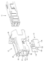
- FIG. 2 is a perspective view of the outer housing, inner module, and retainer.
- FIG. 3 is an exploded perspective view of the inner module.
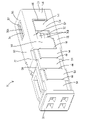
- FIG. 4 is a perspective view of a base member.
- FIG. 5 is a plan view of the base member.
- FIG. 6 is a bottom view of the cover member.
- FIG. 7 is a perspective view of a state in which the terminal group is attached to the base member.
- FIG. 8 is a perspective view of a state in which the cover member is attached to one side of the base member.
- FIG. 9 is a perspective view of a state in which cover members are attached to both sides of the base member.
- FIG. 1 is a perspective view of a connector.
- FIG. 2 is a perspective view of the outer housing, inner module, and retainer.
- FIG. 3 is an exploded perspective view of the inner module.
- FIG. 4 is a perspective view of a base member.
- FIG. 5
- FIG. 10 is a side cross-sectional view of the inner module taken along an imaginary plane passing through the front stabilizer and the rear stabilizer.
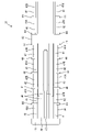
- FIG. 11 is a side cross-sectional view of the inner module cut along an imaginary plane passing through the crimping portion and the fitting hole.
- FIG. 12 is a front sectional view of the inner module.
- FIG. 13 is a side cross-sectional view of the connector.
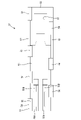
- FIG. 14 is a configuration diagram of a branch structure using connectors.
- the connector of the present disclosure is (1) An inner module having a plurality of terminal groups each having a pair of terminals connected to a pair of conductive paths, and an outer housing accommodating the inner module, wherein the outer housing accommodates the inner module.
- the inner module has an inner housing configured integrally to support the plurality of the terminal groups, and the inner housing is arranged in front of the plurality of the terminal groups.
- the front wall is composed of one member, and insertion openings are formed at positions corresponding to all of the terminals.
- the outer housing is configured to accommodate the inner module having the plurality of terminal groups in the single accommodation chamber, the space in the accommodation chamber is partitioned to separately accommodate the plurality of terminal groups. There is no need to provide walls (walls partitioning in the direction in which a plurality of terminal groups are arranged). Therefore, it is possible to reduce the size in the direction in which the plurality of terminal groups are arranged. Furthermore, according to this configuration, the insertion openings corresponding to all the terminals are formed in one member, so that the insertion openings can be prevented from being misaligned.
- the inner housing has a base member that partitions the plurality of terminal groups, and a pair of cover members that are assembled to the base member so as to sandwich the base member from both sides, and the pair of cover members are engaged with each other.
- the base member has a first locking receiving portion for locking the locking portion of one of the pair of cover members, and the locking portion of the other cover member is locked. and a second locking receiving portion, and the first locking receiving portion and the second locking receiving portion preferably have tapered surfaces that are inclined in opposite directions. According to this configuration, it is possible to facilitate the work of assembling the pair of cover members that are assembled from opposite directions to the base member.
- the base member has a guide portion provided along the mounting direction of the cover member. According to this configuration, the cover member can be guided by the guide portion when the cover member is assembled to the base member.
- the locking portion of the cover member has a comb shape. According to this configuration, even if the inner housing is of a small size, the cover member is engaged with the base member at a plurality of points. Hard to come off.
- first locking receiving portion and the second locking receiving portion are arranged in a positional relationship that is point-symmetrical to each other when viewed from the front. According to this configuration, the pair of cover members can be used as a common member.
- the inner housing has a base member having partitions for partitioning the plurality of terminal groups, and a pair of cover members assembled to the base member so as to sandwich the base member from both sides, wherein the cover members are: It is preferable to have a locking portion locked to the base member, and a deflection restricting portion connected to the locking portion and positioned so as to sandwich the electric wire connected to the terminal group between the partition portion. According to this configuration, it is possible to restrict the bending of the electric wire to the side opposite to the partition side.
- the terminal group has a crimping portion that is crimped onto the electric wire
- the cover member has a fitting hole in front of the deflection restricting portion into which the crimping portion is fitted. According to this configuration, it is possible to prevent the wires connected to the terminal group from being pulled out rearward by fitting the crimping portion into the fitting hole.
- FIGS. 1 to 14 A first embodiment embodying the connector of the present disclosure will be described with reference to FIGS. 1 to 14.
- FIG. 1 the directions shown in FIGS. 1 to 4 and 7 to 13 are defined as upward and downward as they are.
- the left and right directions shown in FIGS. 1 to 11 and 13 are defined as forward and rearward, respectively.
- the left and right directions are defined as left and right, respectively, when the connector is viewed from the front.
- a connector 10 according to the first embodiment shown in FIG. 1 is configured as, for example, a branching connector that is connected in the middle of a trunk harness.
- the connector 10 includes an inner module 11, an outer housing 12, and a retainer 13, as shown in FIG.
- the inner module 11 is housed in the outer housing 12 .
- the inner module 11 has an inner housing 21 and a pair of terminal groups 22 .
- the number of terminal groups 22 is the same as the number of systems of conductive paths that constitute the trunk harness.
- the inner housing 21, as shown in FIG. 3, includes one base member 31 made of a single component and a pair of cover members 32. As shown in FIG.
- the inner housing 21 is integrally constructed by assembling a pair of cover members 32 to the base member 31 from both upper and lower sides of the base member 31 . That is, in the first embodiment, the vertical direction corresponds to the mounting direction of the base member 31 .
- the base member 31 and the cover member 32 are components made of an insulating material such as synthetic resin.
- the inner housing 21 supports the pair of terminal groups 22 and is configured integrally with the pair of terminal groups 22 as the inner module 11 .
- the base member 31 has a partition portion 40 that partitions the pair of terminal groups 22, as shown in FIGS.
- the partition part 40 has a plate shape and is arranged with its plate surface directed in the vertical direction.
- the partition part 40 has a form extending in the front-rear direction.
- the base member 31 has a first engagement receiving portion 41 and a second engagement receiving portion 42 provided on both left and right sides of the partition portion 40, as shown in FIGS.
- the first locking receiving portion 41 and the second locking receiving portion 42 are configured to extend vertically from both left and right sides of the partition portion 40 .
- the first locking receiving portions 41 and the second locking receiving portions 42 are alternately arranged in the front-rear direction.
- the first locking receiving portion 41 and the second locking receiving portion 42 are arranged in a positional relationship that is point symmetrical to each other in a front view viewed from the front (direction orthogonal to the direction in which the cover member 32 is attached to the base member 31). It is
- the left and right first locking receiving portions 41 have first tapered surfaces 41A inclined along the assembly direction on their outer surfaces.
- the left and right second locking receiving portions 42 have second tapered surfaces 42A on the outer side surfaces that are inclined along the assembly direction.
- the first tapered surface 41A is slanted upward and inward in the left-right direction
- the second tapered surface 42A is slanted downward and inward in the left-right direction.
- the first tapered surface 41A and the second tapered surface 42A intersect when viewed from the front.
- the first locking receiving portion 41 has a first locking receiving surface 41B, as shown in FIGS.
- the second locking receiving portion 42 has a second locking receiving surface 42B, as shown in FIGS. 4 and 12 .
- the first locking receiving portion 41 and the second locking receiving portion 42 are vertically displaced from each other. It has a structure in which 32 claw portions 55 are fitted.
- the base member 31 has a caulking ring fitting groove 43 into which the caulking ring 76 is fitted, as shown in FIGS.
- the caulking ring fitting grooves 43 are formed on both upper and lower sides of the partition portion 40 and extend along the horizontal direction.
- the caulking ring fitting groove 43 is arranged between the first locking receiving portion 41 and the second locking receiving portion 42 which are arranged in the front-rear direction.
- the base member 31 has a guide portion 44 provided along the assembly direction of the cover member 32, as shown in FIGS.
- the guide portion 44 is provided on the first tapered surface 41A or the second tapered surface 42A.
- the guide portions 44 are provided on all the first tapered surfaces 41A and the second tapered surfaces 42A on both the left and right sides.
- the base member 31 has terminal receiving grooves 46 formed on both upper and lower sides of the partition portion 40, as shown in FIGS.
- the terminal receiving groove 46 is elongated in the front-rear direction and opens outward in the vertical direction.
- Two terminal receiving grooves 46 are provided side by side on the left and right.
- the two terminal accommodating grooves 46 aligned laterally are arranged between the partition portion 40, the first locking receiving portion 41 and the second locking receiving portion 42 on both left and right sides, and the two terminal receiving grooves 46 aligned laterally. It is partitioned by a partition wall 47 that
- the base member 31 has a front wall 48 in front of the terminal receiving groove 46, as shown in FIGS.
- the front wall 48 has a rectangular shape when viewed from the front.
- the front wall 48 continues to the front end of the partition section 40 .
- the front wall 48 is formed with a plurality of insertion openings 48A penetrating the front wall 48 in the front-rear direction.
- a plurality of insertion openings 48 ⁇ /b>A are provided corresponding to all terminal receiving grooves 46 . That is, a plurality of insertion openings 48A are provided corresponding to all terminals 60 arranged in all terminal receiving grooves 46, respectively.
- the front wall 48 is made entirely of one member.
- the cover member 32 has a plate-like cover main body 50, locking portions 51 extending upward or downward from both left and right sides of the cover main body 50, and crimping ring restricting portions 52. As shown in FIG. 3, the cover member 32 has a plate-like cover main body 50, locking portions 51 extending upward or downward from both left and right sides of the cover main body 50, and crimping ring restricting portions 52. As shown in FIG. 3, the cover member 32 has a plate-like cover main body 50, locking portions 51 extending upward or downward from both left and right sides of the cover main body 50, and crimping ring restricting portions 52. As shown in FIG.
- the cover main body 50 is long in the front-rear direction and arranged with its plate surface facing in the vertical direction.
- a front side retaining recess 50A and a rear side retaining recess 50B are formed on the inner surface of the cover body 50 .
- the rear retaining recess 50B is arranged behind the front retaining recess 50A.
- the engaging portions 51 are comb-shaped and protrude upward or downward from the left and right sides of the cover body 50 .
- the locking portion 51 has locking arms 54 extending upward or downward from both left and right sides of the cover body 50 .
- a plurality of locking arms 54 are provided at intervals along the front-rear direction.
- the locking arm 54 has a plate shape and is arranged with the plate surface facing in the left-right direction.
- a claw portion 55 is provided at the tip portion of the locking arm 54 .
- the locking arm 54 is flexurally deformed at its distal end with its proximal end serving as a fixed end.
- the locking arms 54 are provided alternately on the left and right in the front-rear direction.
- the crimping ring restricting portion 52 vertically sandwiches the crimping ring 76 between itself and the bottom surface of the crimping ring fitting groove 43 to restrict movement in the vertical direction.
- the cover body 50 has a deflection restricting portion 56 at its rear end.
- the deflection restricting portion 56 continues to the locking portion 51 , more specifically to the locking arm 54 .
- the deflection restricting portion 56 extends in the left-right direction from the base end portion of the locking arm 54 and is arranged on the opposite side of the partition portion 40 with the electric wire 70 therebetween.
- the cover body 50 has a fitting hole 57 in front of the deflection restricting portion 56, as shown in FIG. A crimping portion 76A of a crimping ring 76 is fitted into the fitting hole 57 .
- the terminal group 22 has a pair of terminals 60 .
- the terminal 60 has an elongated shape in the front-rear direction as a whole.
- a rectangular tube portion 61 is formed at the front end portion of the terminal 60
- an open barrel-shaped terminal side crimping portion 62 is formed at the rear end portion of the terminal 60 .
- the terminal-side crimping portion 62 is crimped to be electrically connected to the dividing portion 72 of the conductive path 71 .
- the pair of conductive paths 71 are configured as a twisted pair of wires.
- a front stabilizer 61A is formed at the front end of the rectangular tubular portion 61 and protrudes in a direction perpendicular to the front-rear direction.
- a rear stabilizer 61B is formed at the rear end of the rectangular tubular portion 61 and protrudes in a direction perpendicular to the front-rear direction.
- the terminal-side crimping portion 62 is fixed to the dividing portion 72 of the conductive path 71 so as to be conductive.
- a branched portion of each conductive path 71 is a dividing portion 72 that divides each conductive path 71 .
- the insulating coating 73 is removed and the conductor 74 is exposed.
- a pair of conductors 74 covered with an insulating coating 73 are collectively surrounded by a sheath 75 to form the electric wire 70 .
- Wire 70 has a crimp ring 76 attached to the end of sheath 75 .
- the crimping ring 76 has a crimping portion 76A that is crimped to a part of the dividing portion 72, and a positioning portion 76B that protrudes outward from the dividing portion 72 in the left-right direction.
- the terminal 60 fixed to the conductive path 71 extends linearly from the divided portion 72 of the conductive path 71 .
- the terminals 60 are housed in the terminal housing grooves 46 of the base member 31 .
- the terminals 60 on the upper side are supported by the inner housing 21 in an upside-down position with respect to the terminals 60 on the lower side.
- the outer housing 12 is a rectangular tubular single component made of an insulating material such as synthetic resin. As shown in FIG. 2, the outer housing 12 includes a pair of laterally symmetric side wall portions 81, a bottom wall portion 82 formed by connecting lower edges of the side wall portions 81 on both left and right sides, and a pair of side wall portions 81 on both left and right sides. and an upper wall portion 83 in which the upper edges are connected to each other.
- the outer housing 12 has only one accommodation chamber 84 that accommodates the inner module 11 .
- the accommodation chamber 84 is provided inside the outer housing 12 . Both front and rear ends of the storage chamber 84 are open to the outside of the outer housing 12 .
- the interior of the storage chamber 84 is not partitioned by a partition wall or the like.
- a first locked portion 81A and a second locked portion 81B are formed on the outer surfaces of the left and right side wall portions 81 (surfaces on the side opposite to the other side wall portion 81 side). is provided.
- the first locked portion 81A and the second locked portion 81B protrude outward in the left-right direction (the side opposite to the side wall portion 81 side).
- the first locked portion 81A is provided below and spaced from the second locked portion 81B.
- an elastic retaining piece 85 is formed on the inner surface of the upper wall portion 83 .
- the elastic retaining piece 85 can be elastically displaced vertically relative to the upper wall portion 83 .
- a lock arm 86 is formed on the outer housing 12 so as to cover the outer surface of the upper wall portion 83 with a space therebetween.
- the lock arm 86 extends rearward from the front end of the outer housing 12 in a cantilevered manner and is elastically deformable.
- the retainer 13 has a bottom wall 13A and a pair of side walls 13B.
- a pair of side walls 13B rises upward from both left and right ends of the bottom wall 13A.
- a retainer-side convex portion 13C that protrudes upward is provided on the upper surface of the bottom wall 13A.
- the inner surface of the side wall 13B (the surface on the side of the other side wall 13B) is provided with a retainer side recess 13D that is recessed outward (to the side opposite to the side wall 13B).
- the upper end of the retainer-side concave portion 13D serves as a retainer-side engaging portion 13E that is engaged with the first engaged portion 81A or the second engaged portion 81B.
- the retainer 13 is temporarily locked to the outer housing 12 by locking the retainer-side locking portion 13E to the first locked portion 81A.
- the retainer 13 is fully locked with respect to the outer housing 12 by locking the retainer-side locking portion 13E to the second locked portion 81B.
- the terminal group 22 connected to the electric wire 70 is assembled to the base member 31 .
- the terminals 60 are inserted into the openings of the terminal accommodating grooves 46 in an orientation (the orientation shown in FIG. 3) along the extending direction (front-rear direction) of the terminal accommodating grooves 46 .
- a positioning portion 76 ⁇ /b>B of the caulking ring 76 is fitted into the caulking ring fitting groove 43 .
- the cover member 32 is attached to the base member 31 from above.
- the engaging portion 51 is slid along the first tapered surface 41A of the first engaging portion 41 along the guide portion 44, thereby sliding the first engaging portion 41B. to lock.
- the cover member 32 is attached to the base member 31 .
- the other cover member 32 is assembled to the base member 31 as shown in FIG.
- the cover member 32 When the cover member 32 is assembled to the base member 31, as shown in FIG. It is arranged between them and its movement in the vertical direction is restricted. Further, as shown in FIG. 10, the front stabilizer 61A of the terminal 60 fits into the front retaining recess 50A of the cover member 32, and the rear stabilizer 61B of the terminal 60 fits into the rear retaining recess 50B of the cover member 32. As shown in FIG. to fit. Further, as shown in FIG. 11 , the deflection restricting portion 56 of the cover member 32 is arranged on the outer side of the electric wire 70 in the vertical direction. Since the deflection restricting portion 56 continues to the locking portion 51 , the wire 70 is restricted from moving outward in the vertical direction. Further, as shown in FIG.
- the crimping portion 76A of the crimping ring 76 fits into the fitting hole 57 of the cover member 32. As shown in FIG. This restricts the terminal group 22 from coming off rearward.
- the inner module 11 is inserted from behind into the housing chamber 84 of the outer housing 12 .
- the retainer 13 is temporarily locked to the outer housing 12. - ⁇ In the process of insertion, the elastic retaining piece 85 is elastically deformed due to interference with the inner module 11 (the front wall 48 of the base member 31). primary lock).
- the retainer 13 After the inner module 11 is inserted into the outer housing 12 in the normal posture, the retainer 13 is brought into the fully locked state with respect to the outer housing 12 as shown in FIG.
- the retainer-side protrusion 13 ⁇ /b>C is locked (secondary locked) to the outer concave portion 59 of the cover member 32 . This restricts the inner module 11 from coming out of the outer housing 12 .
- FIG. 14 shows an application example of the connector 10.
- FIG. The connector 10, as shown in FIG. 14, is connected in the middle of a trunk harness constituted by a pair of conductive paths 71.
- the connector 10 has a function of branching the communication circuit 91 from the trunk harness.
- the communication circuit 91 is formed as a printed circuit on the circuit board 92 .
- a board connector (not shown) is mounted on the circuit board 92 .
- the board connector has two pairs of tab-like branch terminals 93 attached to a board-side housing (not shown) fixed to the circuit board 92 .
- the branch side terminal 93 is connected to the communication circuit 91 .
- the communication circuit 91 is branched from the trunk harness.
- the outer housing 12 accommodates the inner module 11 having the plurality of terminal groups 22 in the single accommodation chamber 84, so that the plurality of terminal groups 22 can be accommodated.
- the connector 10 can be reduced in size in the direction in which the plurality of terminal groups 22 are arranged.
- the insertion openings 48A corresponding to all the terminals 60 are formed in the front wall 48 which is one member, it is possible to prevent the insertion openings 48A from being displaced.
- first tapered surface 41A of the first locking receiving portion 41 and the second tapered surface 42A of the second locking receiving portion 42 are arranged along the mounting direction of the cover member 32 in a front view from the front. They are slanted, and the slanting directions are opposite to each other. Therefore, it is possible to facilitate the assembly work of the pair of cover members 32 that are assembled to the base member 31 from opposite directions.
- the base member 31 has a guide portion 44 provided along the mounting direction of the cover member 32 . Therefore, when the cover member 32 is assembled to the base member 31 , the cover member 32 can be guided by the guide portion 44 .
- the engaging portion 51 has a comb shape. Therefore, even if the inner housing 21 is of a small size, the cover member 32 is engaged with the base member 31 at a plurality of points, so that force is applied in the direction in which the cover member 32 and the base member 31 separate from each other. Also, it is hard to come off.
- first locking receiving portion 41 and the second locking receiving portion 42 are arranged in a positional relationship that is point-symmetrical to each other when viewed from the front. Therefore, the pair of cover members 32 can be used as a common member.
- the cover member 32 is positioned so as to sandwich the electric wire 70 connected to the terminal group 22 between the locking portion 51 locked to the base member 31 and the partition portion 40 connected to the locking portion 51 . and a regulating portion 56 . Therefore, bending of the electric wire 70 toward the side opposite to the partition portion 40 side can be restricted.
- the terminal group 22 has a crimping portion 76A that is crimped onto the electric wire 70
- the cover member 32 has a fitting hole 57 in front of the deflection restricting portion 56 into which the crimping portion 76A is fitted.
- the first locking receiving portion has the first tapered surface and the second locking receiving portion has the second tapered surface.
- a configuration in which the stop receiving portion does not have a tapered surface may be employed.
- the connector has a guide portion, but the connector may have no guide portion.
- the engaging portion has a comb shape, but it may not have a comb shape.
- the first locking receiving portion and the second locking receiving portion are arranged in a point-symmetrical positional relationship.
- the cover member has the deflection restricting portion, but the cover member may have no deflection restricting portion.
- the cover member has a fitting hole into which the crimping portion fits, but it may have no fitting hole.
Landscapes
- Connector Housings Or Holding Contact Members (AREA)
Abstract
La présente invention concerne un connecteur (10) comprenant : un module interne (11) qui a une pluralité de groupes de bornes (22) ayant une paire de bornes (60) connectées respectivement à une paire de chemins conducteurs (71) ; et un boîtier externe (12) recevant le module interne (11). Le boîtier externe (12) présente uniquement une chambre de réception (84) qui loge le module interne (11). Le module interne (11) a un boîtier interne (21) qui supporte la pluralité de groupes de bornes (22) et est structuré d'un seul tenant. Le boîtier interne (21) a une paroi avant (48) disposée devant la pluralité de groupes de bornes (22). La paroi avant (48) est constituée d'un seul élément, et comporte des orifices d'insertion (48A) formés à des positions correspondant à toutes les bornes respectives (60).
Priority Applications (2)
| Application Number | Priority Date | Filing Date | Title |
|---|---|---|---|
| CN202280040961.8A CN117501553A (zh) | 2021-06-18 | 2022-05-31 | 连接器 |
| JP2023529756A JPWO2022264799A1 (fr) | 2021-06-18 | 2022-05-31 |
Applications Claiming Priority (2)
| Application Number | Priority Date | Filing Date | Title |
|---|---|---|---|
| JP2021101381 | 2021-06-18 | ||
| JP2021-101381 | 2021-06-18 |
Publications (1)
| Publication Number | Publication Date |
|---|---|
| WO2022264799A1 true WO2022264799A1 (fr) | 2022-12-22 |
Family
ID=84527438
Family Applications (1)
| Application Number | Title | Priority Date | Filing Date |
|---|---|---|---|
| PCT/JP2022/022063 WO2022264799A1 (fr) | 2021-06-18 | 2022-05-31 | Connecteur |
Country Status (3)
| Country | Link |
|---|---|
| JP (1) | JPWO2022264799A1 (fr) |
| CN (1) | CN117501553A (fr) |
| WO (1) | WO2022264799A1 (fr) |
Citations (8)
| Publication number | Priority date | Publication date | Assignee | Title |
|---|---|---|---|---|
| JPS5593979U (fr) * | 1978-12-22 | 1980-06-28 | ||
| JPH0650262U (ja) * | 1992-12-16 | 1994-07-08 | 矢崎総業株式会社 | シールドコネクタ |
| WO2017141669A1 (fr) * | 2016-02-19 | 2017-08-24 | 株式会社オートネットワーク技術研究所 | Faisceau de fils |
| JP2018063796A (ja) * | 2016-10-12 | 2018-04-19 | 株式会社オートネットワーク技術研究所 | コネクタ構造 |
| JP2018147558A (ja) * | 2017-03-01 | 2018-09-20 | 株式会社オートネットワーク技術研究所 | 端子ユニット |
| JP2019083213A (ja) * | 2019-03-06 | 2019-05-30 | 株式会社オートネットワーク技術研究所 | コネクタ構造 |
| JP2019114334A (ja) * | 2017-12-21 | 2019-07-11 | 株式会社オートネットワーク技術研究所 | コネクタ |
| WO2021079604A1 (fr) * | 2019-10-23 | 2021-04-29 | 株式会社オートネットワーク技術研究所 | Connecteur de dérivation |
-
2022
- 2022-05-31 WO PCT/JP2022/022063 patent/WO2022264799A1/fr active Application Filing
- 2022-05-31 JP JP2023529756A patent/JPWO2022264799A1/ja active Pending
- 2022-05-31 CN CN202280040961.8A patent/CN117501553A/zh active Pending
Patent Citations (8)
| Publication number | Priority date | Publication date | Assignee | Title |
|---|---|---|---|---|
| JPS5593979U (fr) * | 1978-12-22 | 1980-06-28 | ||
| JPH0650262U (ja) * | 1992-12-16 | 1994-07-08 | 矢崎総業株式会社 | シールドコネクタ |
| WO2017141669A1 (fr) * | 2016-02-19 | 2017-08-24 | 株式会社オートネットワーク技術研究所 | Faisceau de fils |
| JP2018063796A (ja) * | 2016-10-12 | 2018-04-19 | 株式会社オートネットワーク技術研究所 | コネクタ構造 |
| JP2018147558A (ja) * | 2017-03-01 | 2018-09-20 | 株式会社オートネットワーク技術研究所 | 端子ユニット |
| JP2019114334A (ja) * | 2017-12-21 | 2019-07-11 | 株式会社オートネットワーク技術研究所 | コネクタ |
| JP2019083213A (ja) * | 2019-03-06 | 2019-05-30 | 株式会社オートネットワーク技術研究所 | コネクタ構造 |
| WO2021079604A1 (fr) * | 2019-10-23 | 2021-04-29 | 株式会社オートネットワーク技術研究所 | Connecteur de dérivation |
Also Published As
| Publication number | Publication date |
|---|---|
| CN117501553A (zh) | 2024-02-02 |
| JPWO2022264799A1 (fr) | 2022-12-22 |
Similar Documents
| Publication | Publication Date | Title |
|---|---|---|
| US10763600B2 (en) | Connector structure | |
| WO2018070202A1 (fr) | Structure de connecteur | |
| WO2022083683A1 (fr) | Connecteur de câble à blindage intégral | |
| US8562374B2 (en) | Harness connector | |
| CN111201678B (zh) | 连接器 | |
| US10819071B2 (en) | Connector structure that is reconfigurable to accommodate either an STP cable or a UTP cable | |
| KR20090004721A (ko) | 커넥터 및 커넥터 조립 방법 | |
| US11108193B2 (en) | Connector and connector device | |
| US20220302618A1 (en) | Branch connector | |
| WO2022264799A1 (fr) | Connecteur | |
| US11482814B2 (en) | Connector with structure for suppressing rattling of the shield terminal | |
| CN114930652A (zh) | 屏蔽连接器 | |
| US20240063570A1 (en) | Connector | |
| US20200083632A1 (en) | Connector | |
| JP6958589B2 (ja) | 電気コネクタ | |
| US20230170650A1 (en) | Connector assembly | |
| US20230011722A1 (en) | Combo connector | |
| JPH0878117A (ja) | ジョイントコネクタ | |
| JP2022136436A (ja) | コネクタ | |
| JP2023077162A (ja) | コネクタ | |
| CN115588887A (zh) | 连接器系统的端子系统 | |
| JP2011165474A (ja) | ワイヤハーネス接続用コネクタ | |
| JP2007220573A (ja) | コネクタ |
Legal Events
| Date | Code | Title | Description |
|---|---|---|---|
| 121 | Ep: the epo has been informed by wipo that ep was designated in this application |
Ref document number: 22822847 Country of ref document: EP Kind code of ref document: A1 |
|
| WWE | Wipo information: entry into national phase |
Ref document number: 2023529756 Country of ref document: JP |
|
| WWE | Wipo information: entry into national phase |
Ref document number: 202280040961.8 Country of ref document: CN |
|
| NENP | Non-entry into the national phase |
Ref country code: DE |