WO2022264351A1 - データ処理装置及びデータ処理方法 - Google Patents
データ処理装置及びデータ処理方法 Download PDFInfo
- Publication number
- WO2022264351A1 WO2022264351A1 PCT/JP2021/022994 JP2021022994W WO2022264351A1 WO 2022264351 A1 WO2022264351 A1 WO 2022264351A1 JP 2021022994 W JP2021022994 W JP 2021022994W WO 2022264351 A1 WO2022264351 A1 WO 2022264351A1
- Authority
- WO
- WIPO (PCT)
- Prior art keywords
- data
- data transfer
- unit
- input
- control unit
- Prior art date
- Legal status (The legal status is an assumption and is not a legal conclusion. Google has not performed a legal analysis and makes no representation as to the accuracy of the status listed.)
- Ceased
Links
Images




Definitions
- the present disclosure relates to a data processing device and a data processing method.
- HILS Hardware In the Loop Simulator/Simulation
- motor controllers are tested not by operating actual motors, but by operating motors simulated by HILS. For example, if a rotation command is input to the HILS, the HILS virtually operates the motor and outputs torque, rotation speed, rotation angle, etc., so it is possible to test whether the controller can control the motor normally.
- the HILS Since the HILS transmits and receives data to and from the controller of the actual machine, the HILS must have response performance that matches the control cycle of the controller. In particular, in the HILS process of reading inputs, calculating the behavior of the motor, and outputting to the outside, it is important to speed up data transfer within the HILS.
- Methods for speeding up data transfer include DMA (Direct Memory Access) transfer and burst transfer such as AXI (Advanced eXtensible Interface) bus. Also, on the premise that there are a plurality of data transfer paths from the "source” to the "destination", a technique for shortening the total transfer time by simultaneously using the plurality of paths for data transfer (Patent Document 1 technology), etc.
- DMA Direct Memory Access
- AXI Advanced eXtensible Interface
- non-real-time control is allowed to delay to some extent due to preferential use of shared resources by real-time control.
- the shared resource is used for too long by real-time control, it becomes almost impossible to transfer data by non-real-time control.
- the present disclosure has been made in view of the problems as described above, and aims to provide a technology capable of appropriately performing the first control and the second control.
- a data processing device includes an input/output control unit that transmits and receives data to and from an external device, performs an operation based on the data received by the input/output control unit, and outputs the operation result from the input/output control unit.
- a data transfer bus forming a plurality of data transfer paths capable of transferring the data between the input/output control unit and the calculation unit; a route acquisition unit that generates information on the required time required and acquires one data transfer route selected from the plurality of data transfer routes; a route switching unit for switching a route for transferring between the input/output control unit and the arithmetic unit to the one data transfer route acquired by the route acquiring unit; and use of the data transfer bus.
- an execution unit that executes a second control that takes precedence over the control.
- the path for transferring data used for the first control between the input/output control unit and the arithmetic unit is switched to one data transfer path selected from among a plurality of data transfer paths,
- the second control is executed in which the use of the data transfer bus is prioritized over the first control.
- FIG. 1 is a block diagram showing the configuration of a data processing device according to Embodiment 1;
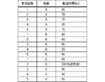
- FIG. FIG. 7 is a diagram showing an example of transfer time measurement results according to the first embodiment;
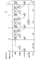
- 4 is a timing chart for explaining real-time control according to Embodiment 1;
- 3 is a block diagram showing the configuration of a data processing device according to Embodiment 3;
- FIG. FIG. 12 is a diagram showing an example of criteria and weights according to Embodiment 3;
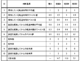
- FIG. 12 is a diagram showing an example of values of criteria according to the third embodiment;
- FIG. FIG. 11 is a block diagram showing a hardware configuration of a data processing device according to another modified example;
- FIG. 11 is a block diagram showing a hardware configuration of a data processing device according to another modified example;
- FIG. 1 is a block diagram showing the configuration of a data processing device 100 according to the first embodiment.
- the data processing device 100 executes first control and second control.
- the first control is the real-time control 101 that is executed periodically, and the second control, such as providing remote access and displaying a GUI, may not be executed periodically.
- the real-time control 101 is mainly executed by the input/output control unit 103, the arithmetic unit 104, the cycle control unit 105, the data transfer bus 106, and the plurality of storage areas 107. In the following description, these components may also be referred to as "components of real-time control 101".
- the non-real-time control 102 is mainly executed by the route acquisition unit 112, the route switching unit 113, the non-real-time control execution unit 114 that is the execution unit, and the non-volatile storage area 115.
- these components may also be referred to as "components of non-real-time control 102".
- the input/output control unit 103 is connected to an external IO (external input/output unit) 110 and controls the external IO 110 to transmit/receive data to/from an external device.
- external IO external input/output unit
- the calculation unit 104 performs calculation based on the data received by the input/output control unit 103, and outputs the calculation result from the input/output control unit to an external device.
- the cycle control unit 105 includes, for example, a timer, and controls the cycle of the real-time control 101.
- the cycle of the real-time control 101 includes the control cycle of the input/output control unit 103 and the calculation unit 104 and the cycle of path synchronization.
- the cycle control unit 105 outputs a computation synchronization trigger and a path synchronization trigger to the input/output control unit 103 and the computation unit 104, thereby controlling the control cycle and the cycle of path synchronization.
- the data transfer bus 106 is a data bus that interconnects the components of the real-time control 101 and the components of the non-real-time control 102 .
- the data transfer bus 106 is, for example, an AXI (Advanced eXtensible Interface) bus, which is a data bus in integrated circuits such as ASIC (Application Specific Integrated Circuit) and FPGA (Field Programmable Gate Array), and PCIe (Peripheral Component Interconnect Express). Switches, Ethernet (registered trademark) switching hubs, and the like.
- AXI Advanced eXtensible Interface
- ASIC Application Specific Integrated Circuit
- FPGA Field Programmable Gate Array
- PCIe Peripheral Component Interconnect Express
- the data transfer bus 106 forms a plurality of data transfer paths that do not need to be prepared as dedicated paths by using data transmission/reception (data transfer) paths.
- a plurality of data transfer paths formed by the data transfer bus 106 are paths through which data can be transferred between the data transfer bus 106 and components.
- the plurality of data transfer paths formed by the data transfer bus 106 are, as shown in FIG. It includes a data transfer path 106a.
- a plurality of storage areas 107 are used for data transfer and the like.
- the plurality of storage areas 107 are three storage areas 107 (storage areas 107A, 107B, and 107C) respectively routed through three data transfer paths 106a.
- the number of storage areas 107 is three in the first embodiment, the number is not limited to three, and one or more storage areas 107 may be provided.
- the input/output control unit 103 notifies the arithmetic unit 104 of data such as signals received via the external IO 110 from the controller of the motor, which is an external device.
- the calculation unit 104 performs a test using a motor model that simulates the behavior of the motor by calculation based on the data, and transmits the rotation speed and torque of the motor obtained by the test to the controller via the external IO 110. .
- the setting of the model and the control cycle used in the calculation unit 104 are set by the user 111 of the data processing device 100 .
- remote access by communication equipment such as UART (Universal Asynchronous Receiver/Transmitter), Ethernet (registered trademark), Wi-Fi (registered trademark) may be used, or direct access such as button operation may be used. may be used.
- An interface function for remote access between the data processing device 100 and the user 111 is provided by the non-real-time control execution unit 114 .
- the non-real-time control execution unit 114 can access all components of the real-time control 101 via the data transfer bus 106 .
- model and the control period used by the computing unit 104 are set by the user 111 after the data processing device 100 is started, the present invention is not limited to this.
- the model and the control cycle may be stored in the non-volatile storage area 115 in advance, and the calculation unit 104 may read them from the non-volatile storage area 115 when the data processing apparatus 100 is started.
- the path acquisition unit 112 generates information on the time required for transfer by each of the plurality of data transfer paths 106a, and acquires one data transfer path 106a selected from among the plurality of data transfer paths 106a.
- transfer time the time required to transfer the same amount of data between the input/output control unit 103 and the calculation unit 104
- the information may also be referred to as "transfer time information”.
- the route acquisition unit 112 presents the transfer time information of the plurality of data transfer routes 106a to the user 111. Then, the user 111 selects one data transfer path 106a from the plurality of data transfer paths 106a with reference to the transfer time information, and the path acquisition unit 112 acquires the one data transfer path 106a.
- the path switching unit 113 switches the path for transferring data used for the real-time control 101 between the input/output control unit 103 and the calculation unit 104 to the one data transfer path 106 a obtained by the path obtaining unit 112 .
- the path switching unit 113 performs the switching by notifying the input/output control unit 103 and the calculation unit 104 of the one data transfer path 106a acquired by the path acquisition unit 112 .
- the non-real-time control execution unit 114 executes non-real-time control 102 in which use of the data transfer bus 106 is prioritized over real-time control 101 .
- the non-real-time control execution unit 114 executes the non-real-time control 102 using a plurality of data transfer paths excluding one data transfer path 106a among the plurality of data transfer paths formed by the data transfer bus 106. do.
- the non-real-time control execution unit 114 executes the non-real-time control 102 using the one data transfer path 106a while the one data transfer path 106a is not transferring data used for the real-time control 101.
- the number of initial measurements is the number of times the data processing device 100 measures the transfer time of each data transfer path 106 a before starting the real-time control 101 .
- the transfer time storage location is the storage area 107 designated by the user 111 where the transfer time measured for each data transfer path 106a is stored.
- the data processing device 100 After the data processing device 100 is powered on, the data processing device 100 automatically performs initial settings.
- the input/output control unit 103 and the arithmetic unit 104 that have been activated store the information set in the nonvolatile storage area 115, that is, the plurality of data transfer paths 106a, the number of initial measurements, and the transfer time. Read storage location information.
- the input/output control unit 103 and the arithmetic unit 104 read/write data from/to the storage area 107 designated by the storage location of the transfer time using each data transfer path 106a for the number of times of initial measurement. Measure the time required.
- the input/output control unit 103 and the calculation unit 104 store the measured required time in the storage area 107 designated as the transfer time storage location.
- the sum of the times required to read and write data between the input/output control unit 103 and the storage area 107 and between the arithmetic unit 104 and the storage area 107 is It corresponds to the transfer time of each data transfer path 106a. Also, in the first embodiment, the data transfer path 106a and the storage area 107 correspond to each other. Therefore, when the above measurement is performed in the example of FIG. 1, the measurement result of the transfer time for the data transfer path 106a passing through the storage areas 107A, 107B, and 107C is obtained as shown in FIG. In FIG.
- the number of initial measurements is "5"
- the transfer time measurement results for five times are obtained for each of the storage areas 107A, 107B, and 107C through which the data transfer path 106a passes.
- the data transfer paths 106a passing through the storage areas 107A, 107B, and 107C may also be referred to as paths A, B, and C, respectively, as shown in FIG.
- the user 111 accesses the route acquisition unit 112 by remote access.
- the route acquisition unit 112 accesses the storage area 107 , generates transfer time information based on the transfer time shown in FIG. 2 for each data transfer route, and presents it to the user 111 .
- the transfer time information includes at least one of the following (1) to (7).
- Transfer time held (transfer time for the number of holds) (2) Average value of held transfer time (3) Worst time (longest time) of held transfer time (4) Best transfer time held (shortest time) (5) Average value of the transfer time from when the data processor 100 was started (6) Worst transfer time from when the data processor 100 was started (7) When the data processor 100 was started Best time of transfer time ever since
- each storage area 107 retains the transfer time up to the maximum retention number of transfer times. For example, if the maximum number of transfer times to be held is set to 10, each storage area 107 holds up to 10 transfer times. Note that the values (1) to (7) above may be reset (deleted) by the user 111 at any timing.
- the user 111 selects one data transfer path 106 a to be used for the real-time control 101 from among the plurality of data transfer paths 106 a by referring to the presented transfer time information, and sets it in the path acquisition unit 112 .
- the path acquisition unit 112 acquires one data transfer path 106a selected from the plurality of data transfer paths 106a.
- the path switching unit 113 notifies the input/output control unit 103 and the computing unit 104 of the one data transfer path 106a obtained by the path obtaining unit 112 via the data transfer bus 106. As a result, the path switching unit 113 selects the data transfer path 106a obtained by the path obtaining unit 112 as the path for transferring the data used for the real-time control 101 between the input/output control unit 103 and the calculation unit 104. switch.
- the user 111 After selecting one data transfer path 106a, the user 111 sets the control cycle of the real-time control 101 in the cycle control unit 105, and the real-time control 101 of the control cycle starts.
- FIG. 3 is a timing chart for explaining the real-time control 101.
- FIG. 3 An example of the real-time control 101 will be described below.
- the route for transferring data used for the real-time control 101 between the input/output control unit 103 and the arithmetic unit 104 may be referred to as a "use route”.
- the route 106a may also be referred to as an "unused route”.
- the cycle control unit 105 outputs a computation synchronization trigger to the computation unit 104 and the input/output control unit 103 for each control cycle set by the user 111 .
- the input/output control unit 103 receives input 1 from the external IO 110 and stores it in the storage area 107 corresponding to the usage path.
- the route A is selected as the route to be used at this time, and the input 1 is stored in the storage area 107A corresponding to the route A.
- the input/output control unit 103 receives input 2 from the external IO 110 in the same manner as the first trigger for operation synchronization, and stores input 2 in the storage area 107A.
- the calculation unit 104 reads the input 1 from the storage area 107A, uses the input 1 in the calculation of the model predefined by the user 111, and stores the calculation result as the output 1 in the storage area 107A.
- the input/output control unit 103 receives the input 3 from the external IO 110, stores the input 3 in the storage area 107A, and then reads the output 1 from the storage area 107A and outputs it to the external IO 110. .
- the calculation unit 104 reads the input 2 from the storage area 107A and stores the calculation result as the output 2 in the storage area 107A in the same manner as the second calculation synchronization trigger. After that, the same process as the third trigger for synchronization of operation is repeated unless the use path is changed.
- each storage area 107 has an area capable of storing two or more inputs and two or more outputs.
- the input 2 from the input/output control unit can be stored at an address different from the address of the input 1 in the storage area 107. , input 2 can be avoided from being overwritten.
- the non-real-time control execution unit 114 uses the input/output control unit 103 and the calculation unit 104 to perform non-real-time control 102 such as measurement of transfer time and acceptance of switching of usage paths in parallel with real-time control 101. Run. For example, in parallel with the real-time control 101, the input/output control unit 103 and the calculation unit 104 measure the transfer time of each of the plurality of data transfer paths 106a in the same manner as the initial measurement. The measurement results are held for the "maximum holding number of transfer times" set in advance by the user 111, and are overwritten from the oldest one including the transfer time measured at the time of initial measurement.
- the input/output control unit 103 and the calculation unit 104 in accordance with the measurement interval of the unused route, during the remaining time obtained by subtracting the time of the real-time control 101 from the time of the control period, transfer data equivalent to the data transfer used for measuring the used route. Data transfer is performed and the transfer time of the unused path is measured.
- the remaining time referred to here is, for example, the time after completion of the IO control by the input/output control unit 103 and the time after the calculation unit 104 outputs the result. For example, if the unused path measurement interval is "10", the input/output control unit 103 and the calculation unit 104 measure the transfer time of the unused path each time the trigger for calculation synchronization is received ten times. . Note that the user 111 sets the measurement interval of the unused route in advance.
- the user 111 refers to the transfer time information presented by the route acquisition unit 112 and sets one data transfer route 106a to the route acquisition unit 112 at any timing. After the setting of one data transfer path 106a is reflected in the input/output control unit 103 and the calculation unit 104, and the input/output control unit 103 and the calculation unit 104 receive the path synchronization trigger from the cycle control unit 105, One data transfer path 106a is switched.
- the user 111 notifies the route acquisition unit 112 of a setting to switch the route to be used from route A to route B, for example.
- the route switching unit 113 notifies the input/output control unit 103 and the calculation unit 104 that the route B is selected as the route to be used. At this point, the input/output control unit 103 and the calculation unit 104 do not switch the route to be used to the route B.
- the path switching unit 113 instructs the cycle control unit 105 to output a path synchronization trigger.
- the cycle control unit 105 outputs a path synchronization trigger in the cycle following the cycle in which the instruction from the path switching unit 113 is received.
- the input/output control unit 103 and the calculation unit 104 that have received the path synchronization trigger switch the used path to the path B from the cycle following the cycle in which the path synchronization trigger is received.
- the use path is switched to one data transfer path 106a selected from the plurality of data transfer paths 106a, and A non-real-time control 102 is performed in which the use of the bus 106 is prioritized over the real-time control 101 .
- a non-real-time control 102 is performed in which the use of the bus 106 is prioritized over the real-time control 101 .
- the transfer time information is presented to the user 111, and one data transfer path 106a is selected by the user 111. Therefore, the real-time control 101 and the non-real-time control 102 are performed at a rate desired by the user 111. be able to.
- the second control is the non-real-time control 102 in the above description, it is not limited to this.
- the second control may be real-time control with a longer period than the real-time control that is the first control.
- the transfer time information includes at least one of (1) to (7) above, but in Embodiment 2, the transfer time information is based on each of the plurality of data transfer paths 106a. Contains information about data loss that occurred during transfer. Data loss is a data transfer failure in which the transfer time is equal to or longer than the control cycle, and data loss information includes, for example, at least one of the following (11) to (13).
- the input/output control unit 103 and the calculation unit 104 store the number of lost data and the number of transfer times retained in the storage area 107, and the route acquisition unit 112 accesses the storage area 107 to obtain the transfer time including data loss information. Information is generated and presented to the user 111 .
- the transfer time information includes data loss information.
- one data transfer path 106a can be selected in consideration of the possibility of data loss, so real-time control 101 and non-real-time control 102 can be performed appropriately.
- FIG. 4 is a block diagram showing the configuration of the data processing device 100 according to the third embodiment.
- constituent elements that are the same as or similar to the above-described constituent elements are denoted by the same or similar reference numerals, and different constituent elements will be mainly described.
- the data processing apparatus 100 has the same configuration as the configuration in FIG. 1 with an automatic selection unit 116 added.
- Automatic selector 116 is a component of non-real-time control 102 .
- FIG. 5 is a diagram showing judgment criteria corresponding to transfer time information and weights set in advance by the user 111 for the judgment criteria.
- the criteria are identified by ID1 to ID110.
- the automatic selection unit 116 calculates the score of each of the plurality of data transfer paths 106a based on the results of the criteria shown in FIG. 5 and the weights shown in FIG. automatically selects one data transfer path 106a with a higher value.
- FIG. 6 is a diagram showing values for each criterion of routes A to C.
- ID1 to ID10 in FIG. 6 correspond to ID1 to ID10 in FIG.
- the criterion for ID1 in FIG. 6 is the "average value of the retained transfer time" indicated by ID1 in FIG. are respectively "177", "192" and "195".
- the automatic selection unit 116 assigns X, X-1, . .
- the values of ID1 criteria for paths A, B, and C in FIG. 6 are "177,” “192,” and "195.”
- the route A is given “3 points”
- the route B is given “2 points”
- the route C is given "1 point”.
- the automatic selection unit 116 assigns the same score to them, and then assigns the same score to the data transfer path 106a with the next smallest criterion value.
- a score obtained by subtracting the number of transfer paths 106a is given.
- the values of the criteria for ID7 of routes A, B, and C in FIG. 6 are "0", “0", and "1". ”, and “1 point” is given to the route C.
- the automatic selection unit 116 obtains a multiplication score by multiplying the given score by the weight of each criterion set in advance by the user 111 .
- the weight of ID2 in FIG. 5 is "0.5"
- the points given to routes A, B, and C for ID2 in FIG. Therefore, the multiplication points for routes A, B, and C of ID2 are "1,5 points", "1 point", and "0.5 point” as shown in FIG.
- the automatic selection unit 116 obtains such multiplication points for each criterion.
- the automatic selection unit 116 obtains the total points obtained by totaling the multiplication points for each of the paths A, B, and C, and automatically selects the data transfer path 106a with the highest total score.
- the total points of the routes A, B, and C are "14.7 points”, “11.8 points”, and "5.1 points”. is automatically selected as the data transfer path 106a.
- the user 111 presets the automatic selection cycle in the cycle control unit 105 .
- the period control section 105 outputs a trigger signal to the automatic selection section 116 for each period set as the automatic selection period.
- the automatic selection unit 116 selects the transfer time between the input/output control unit 103 and the calculation unit 104 and the data processing device from the storage area 107 storing the transfer time.
- the average value, worst value, and best value of the transfer time after starting the data processing device 100, the number of lost data, and the number of lost data and the loss rate after starting the data processing device 100 are read or calculated as appropriate. Get by.
- the automatic selection unit 116 calculates and acquires the average value, worst value, best value, and loss rate.
- the automatic selection unit 116 calculates the total score of each route based on the acquired transfer time information and the predetermined weight, and automatically selects one data transfer route 106a based on the total score.
- the route acquisition unit 112 acquires one data transfer route 106 a automatically selected by the automatic selection unit 116 .
- the data processing device 100 performs the same processing as in the first and second embodiments, thereby transferring the data used for the real-time control 101 between the input/output control unit 103 and the calculation unit 104. Switch to one data transfer path 106a.
- one data transfer path 106a is automatically selected based on the transfer time information and the predetermined weight. can be reduced.
- the data processing device 100 may be configured to enable selection of enabling or disabling the operation of the automatic selection unit 116 . Then, when the operation of the automatic selection unit 116 is disabled, as in the first embodiment, the transfer time information is presented to the user 111 by the route acquisition unit 112, and one data transfer route from the user 111 106a may be performed.
- the input/output control unit 103, the calculation unit 104, the cycle control unit 105, the data transfer bus 106, the route acquisition unit 112, the route switching unit 113, and the non-real-time control execution unit 114 are hereinafter referred to as the “input/output control unit 103 etc.”
- the input/output control unit 103 and the like are realized by the processing circuit 81 shown in FIG. That is, the processing circuit 81 performs an operation based on the input/output control unit 103 that transmits/receives data to/from an external device, and the data received by the input/output control unit 103, and outputs the operation result from the input/output control unit 103.
- a data transfer bus 106 forming a plurality of data transfer paths 106a capable of transferring data between the arithmetic unit 104, the input/output control unit 103, and the arithmetic unit 104, and transfer by each of the plurality of data transfer paths 106a.
- a route acquisition unit 112 that generates information on the required time and acquires one data transfer route 106a selected from among a plurality of data transfer routes 106a, and data used for real-time control that is executed every cycle.
- a route switching unit 113 for switching the transfer route between the input/output control unit 103 and the arithmetic unit 104 to one data transfer route 106a acquired by the route acquisition unit 112, and the use of the data transfer bus 106 are controlled in real time.
- Non-real-time control execution unit 114 that executes non-real-time control that is given priority to.
- Dedicated hardware may be applied to the processing circuit 81, or a processor that executes a program stored in a memory may be applied.
- Processors include, for example, central processing units, processing units, arithmetic units, microprocessors, microcomputers, and DSPs (Digital Signal Processors).
- processing circuitry 81 may be, for example, a single circuit, multiple circuits, programmed processors, parallel programmed processors, ASICs, FPGAs, or combinations thereof. .
- Each function of each unit such as the input/output control unit 103 may be realized by a circuit in which processing circuits are distributed, or the functions of each unit may be collectively realized by one processing circuit.
- the processing circuit 81 When the processing circuit 81 is a processor, the functions of the input/output control unit 103 and the like are realized by combining with software and the like.
- Software and the like correspond to, for example, software, firmware, or software and firmware.
- Software or the like is written as a program and stored in memory.
- a processor 82 applied to a processing circuit 81 reads out and executes a program stored in a memory 83 to implement the functions of each section. That is, the data processing device 100, when executed by the processing circuit 81, generates information on the required time required for transfer by each of the plurality of data transfer paths 106a, and selects from among the plurality of data transfer paths 106a.
- a step of acquiring another data transfer path 106a, and a path for transferring data used for real-time control executed in each period between the input/output control unit 103 and the arithmetic unit 104 are performed by the acquired one data transfer path 106a.
- this program causes the computer to execute the procedures and methods of the input/output control unit 103 and the like.
- the memory 83 is, for example, a non-volatile or Volatile semiconductor memory, HDD (Hard Disk Drive), magnetic disk, flexible disk, optical disk, compact disk, mini disk, DVD (Digital Versatile Disc), their drive devices, etc., or any storage media that will be used in the future There may be.
- HDD Hard Disk Drive
- magnetic disk flexible disk
- optical disk compact disk
- mini disk mini disk
- DVD Digital Versatile Disc
- each function such as the input/output control unit 103 is implemented by either hardware or software has been described above.
- the configuration is not limited to this, and a configuration in which a part of the input/output control unit 103 and the like is realized by dedicated hardware and another part is realized by software or the like may be employed.
- the input/output control unit 103 is realized by a processing circuit 81 as dedicated hardware, an interface, a receiver, and the like, and the processing circuit 81 as a processor 82 executes programs stored in the memory 83. Its function can be realized by reading and executing it.
- the processing circuit 81 can implement each of the functions described above by means of hardware, software, etc., or a combination thereof.
- 100 data processing device 101 real-time control, 102 non-real-time control, 103 input/output control unit, 104 calculation unit, 105 period control unit, 106 data transfer bus, 106a data transfer path, 107, 107A, 107B, 107C storage area, 111 user, 112 route acquisition unit, 113 route switching unit, 114 non-real-time control execution unit, 116 automatic selection unit.
Landscapes
- Data Exchanges In Wide-Area Networks (AREA)
- Bus Control (AREA)
Abstract
第1制御及び第2制御を適切に行うことが可能な技術を提供することを目的とする。データ処理装置は、複数のデータ転送経路の中から選択された一のデータ転送経路を取得する経路取得部と、周期ごとに実行される第1制御に用いられるデータを入出力制御部と演算部との間において転送する経路を、経路取得部で取得された一のデータ転送経路に切り替える経路切替部と、データ転送用バスの使用が第1制御に優先される第2制御を実行する実行部とを備える。
Description
本開示は、データ処理装置及びデータ処理方法に関する。
リアルタイムの制御が必要な装置を試験する試験装置として、試験されるべき実機に代わって当該実機の振る舞いを模擬するHILS(Hardware In the Loop Simulator/Simulation)がある。
例えばモータ制御の分野においては、実際のモータを動作させるのではなく、HILSで模擬されたモータを動作させることによって、モータのコントローラを試験する。例えば回転指令をHILSに入力すれば、HILSは、モータを仮想的に動作させてトルクや回転速度、回転角度などを出力するので、コントローラが正常にモータを制御きるかを試験できる。
HILSは、実機のコントローラとの間でデータを送受信するため、コントローラの制御周期に見合う応答性能がHILSに必要となる。特に、入力を読み込み、モータの振る舞いを計算し、外部に出力するというHILSの過程においては、HILS内のデータ転送を高速化することが重要である。
データ転送を高速化する方法としては、DMA(Direct Memory Access)転送及びAXI(Advanced eXtensible Interface)バスなどのバースト転送が挙げられる。また、「送信元」から「送信先」までのデータ転送経路が複数あることを前提といて、その複数の経路を同時にデータ転送に使用することでトータルの転送時間を短くする技術(特許文献1の技術)などが挙げられる。
特許文献1の技術では、一つの制御についてデータ転送経路を用いることによりデータ転送を高速化できるが、複数の制御がデータ転送経路を共有リソースとして共用することを考慮していない。このような特許文献1の技術において複数の制御を行おうとすると、共有リソースを一方の制御に最大限使用して当該一方の制御を高速化することになる。この結果、他方の制御が使用できる共有リソースが少なくなり、他方の制御に遅延などの影響が出ることがある。
ここで、複数の制御に、リアルタイム制御及び非リアルタイム制御を適用した場合、リアルタイム制御が共有リソースを優先的に使用することによって、非リアルタイム制御がある程度遅れることは許される。しかしながら、リアルタイム制御による共有リソースの使用時間が長すぎる場合には、非リアルタイム制御のデータ転送をほとんど行うことができなくなる。この結果、リアルタイム制御の応答性能を満足しつつ、非リアルタイム制御の応答遅延もできるだけ小さくしたいという要求を満足することができないという問題があった。
そこで、本開示は、上記のような問題点に鑑みてなされたものであり、第1制御及び第2制御を適切に行うことが可能な技術を提供することを目的とする。
本開示に係るデータ処理装置は、外部装置とデータを送受信する入出力制御部と、前記入出力制御部で受信された前記データに基づいて演算を行い、その演算結果を前記入出力制御部から出力する演算部と、前記入出力制御部と前記演算部との間において前記データを転送可能な複数のデータ転送経路を形成するデータ転送用バスと、前記複数のデータ転送経路のそれぞれによる転送に要した所要時間の情報を生成し、前記複数のデータ転送経路の中から選択された一のデータ転送経路を取得する経路取得部と、周期ごとに実行される第1制御に用いられる前記データを前記入出力制御部と前記演算部との間において転送する経路を、前記経路取得部で取得された前記一のデータ転送経路に切り替える経路切替部と、前記データ転送用バスの使用が前記第1制御に優先される第2制御を実行する実行部とを備える。
本開示によれば、第1制御に用いられるデータを入出力制御部と演算部との間において転送する経路が、複数のデータ転送経路の中から選択された一のデータ転送経路に切り替えられ、かつ、データ転送用バスの使用が第1制御に優先される第2制御が実行される。これにより、第1制御及び第2制御を適切に行うことができる。
本開示の目的、特徴、局面及び利点は、以下の詳細な説明と添付図面とによって、より明白となる。
<実施の形態1>
図1は、本実施の形態1に係るデータ処理装置100の構成を示すブロック図である。
図1は、本実施の形態1に係るデータ処理装置100の構成を示すブロック図である。
データ処理装置100は、第1制御及び第2制御を実行する。本実施の形態1では、第1制御は、周期ごとに実行されるリアルタイム制御101であり、第2制御は、例えばリモートアクセスの提供及びGUIの表示などの、周期ごとに実行されなくてもよい非リアルタイム制御102である。
リアルタイム制御101は、主に、入出力制御部103と、演算部104と、周期制御部105と、データ転送用バス106と、複数の記憶領域107とによって実行される。以下の説明では、これらの構成要素を「リアルタイム制御101の構成要素」と記すこともある。
一方、非リアルタイム制御102は、主に、経路取得部112と、経路切替部113と、実行部である非リアルタイム制御実行部114、不揮発性記憶領域115とによって実行される。以下の説明では、これらの構成要素を「非リアルタイム制御102の構成要素」と記すこともある。
入出力制御部103は、外部IO(外部入出力部)110と接続されており、外部IO110を制御することによって、外部装置とデータを送受信する。
演算部104は、入出力制御部103で受信されたデータに基づいて演算を行い、その演算結果を入出力制御部から外部装置に出力する。
周期制御部105は、例えばタイマを含み、リアルタイム制御101の周期を制御する。本実施の形態1では、リアルタイム制御101の周期は、入出力制御部103及び演算部104の制御周期及び経路同期の周期を含む。周期制御部105は、入出力制御部103及び演算部104に演算同期用トリガ及び経路同期用トリガを出力することによって、制御周期及び経路同期の周期をそれぞれ制御する。
データ転送用バス106は、リアルタイム制御101の構成要素と非リアルタイム制御102の構成要素とを相互接続するデータバスである。データ転送用バス106は、例えば、ASIC(Application Specific Integrated Circuit)及びFPGA(Field Programmable Gate Array)などの集積回路内のデータバスであるAXI(Advanced eXtensible Interface)バス、PCIe(Peripheral Component Interconnect Express)のスイッチ、及び、イーサネット(登録商標)のスイッチングハブなどである。
データ転送用バス106は、データ送受信(データ転送)のパスを用いることによって、専用の経路として用意されなくてもよい複数のデータ転送経路を形成する。データ転送用バス106によって形成される複数のデータ転送経路は、データ転送用バス106と構成要素との間でデータ転送可能な経路である。本実施の形態1では、データ転送用バス106によって形成される複数のデータ転送経路は、図1に示すように、入出力制御部103と演算部104との間においてデータを転送可能な複数のデータ転送経路106aを含む。
複数の記憶領域107は、データ転送などに使用される。本実施の形態1では、複数の記憶領域107は、3つのデータ転送経路106aにそれぞれ経由される3つの記憶領域107(記憶領域107A,107B,107C)である。なお、本実施の形態1では、記憶領域107の数は3つであるがこれに限ったものではなく、1つ以上の記憶領域107があればよい。
データ処理装置100が、モータ用のHILSとして使用される場合、入出力制御部103は、外部装置であるモータのコントローラから外部IO110を介して受信した信号などのデータを演算部104に通知する。演算部104は、当該データに基づく演算によって、モータの振る舞いを模擬したモータのモデルを用いた試験を行い、それによって得られたモータの回転数やトルクを、外部IO110を介してコントローラに送信する。
演算部104で用いるモデル及び制御周期の設定は、データ処理装置100のユーザ111によって設定される。その設定には、UART(Universal Asynchronous Receiver/Transmitter)、イーサネット(登録商標)、Wi-Fi(登録商標)などの通信機器によるリモートアクセスが用いられてもよいし、ボタン操作などの直接的なアクセスが用いられてもよい。
データ処理装置100とユーザ111との間でリモートアクセスを行うためのインターフェース機能は、非リアルタイム制御実行部114で提供される。なお、非リアルタイム制御実行部114は、データ転送用バス106を介してリアルタイム制御101の全ての構成要素にアクセス可能となっている。
なお以上では、演算部104で用いるモデル及び制御周期は、データ処理装置100の起動後にユーザ111によって設定されると説明したが、これに限ったものではない。例えば、モデル及び制御周期を不揮発性記憶領域115に予め保存しておき、データ処理装置100の起動時に、演算部104が不揮発性記憶領域115から読み込んでもよい。
経路取得部112は、複数のデータ転送経路106aのそれぞれによる転送に要した所要時間の情報を生成し、複数のデータ転送経路106aの中から選択された一のデータ転送経路106aを取得する。以下の説明では、入出力制御部103と演算部104との間の同一データ量の転送に要した所要時間を「転送時間」と記すこともあり、経路取得部112によって生成される転送時間の情報を「転送時間情報」と記すこともある。
本実施の形態1では、経路取得部112は、複数のデータ転送経路106aの転送時間情報をユーザ111に提示する。そして、ユーザ111は、転送時間情報を参考にして複数のデータ転送経路106aの中から一のデータ転送経路106aを選択し、経路取得部112は、当該一のデータ転送経路106aを取得する。
経路切替部113は、リアルタイム制御101に用いられるデータを入出力制御部103と演算部104との間において転送する経路を、経路取得部112で取得された一のデータ転送経路106aに切り替える。本実施の形態1では、経路切替部113は、経路取得部112で取得された一のデータ転送経路106aを入出力制御部103及び演算部104に通知することにより、上記切り替えを行う。
非リアルタイム制御実行部114は、データ転送用バス106の使用がリアルタイム制御101に優先される非リアルタイム制御102を実行する。例えば、非リアルタイム制御実行部114は、データ転送用バス106によって形成される複数のデータ転送経路のうち、一のデータ転送経路106aを除く複数のデータ転送経路を使用して非リアルタイム制御102を実行する。また例えば、非リアルタイム制御実行部114は、一のデータ転送経路106aがリアルタイム制御101に用いられるデータを転送していない期間に一のデータ転送経路106aを使用して非リアルタイム制御102を実行する。
<動作>
次に、データ処理装置100の動作について説明する。なお、「複数のデータ転送経路106a」と、「初期測定回数」と、「転送時間の格納場所」とを含む情報が、事前にユーザ111によって不揮発性記憶領域115に設定されているものとする。初期測定回数とは、データ処理装置100が、リアルタイム制御101を開始する前に、各データ転送経路106aの転送時間を計測する回数である。転送時間の格納場所とは、各データ転送経路106aについて計測された転送時間が格納される場所であり、ユーザ111が指定した記憶領域107である。
次に、データ処理装置100の動作について説明する。なお、「複数のデータ転送経路106a」と、「初期測定回数」と、「転送時間の格納場所」とを含む情報が、事前にユーザ111によって不揮発性記憶領域115に設定されているものとする。初期測定回数とは、データ処理装置100が、リアルタイム制御101を開始する前に、各データ転送経路106aの転送時間を計測する回数である。転送時間の格納場所とは、各データ転送経路106aについて計測された転送時間が格納される場所であり、ユーザ111が指定した記憶領域107である。
データ処理装置100の電源投入後、データ処理装置100は初期設定を自動的に行う。本実施の形態1では初期設定として、起動された入出力制御部103及び演算部104は、不揮発性記憶領域115に設定された情報、すなわち複数のデータ転送経路106a、初期測定回数、転送時間の格納場所の情報を読み込む。そして、入出力制御部103及び演算部104は、初期測定回数だけ、各データ転送経路106aを用いて、転送時間の格納場所で指定された記憶領域107に対してデータの読み書きを行い、それに要した所要時間を計測する。それから、入出力制御部103及び演算部104は、計測された所要時間を、転送時間の格納場所で指定された記憶領域107に格納する。
なお、各データ転送経路106aについて、入出力制御部103と記憶領域107との間、及び、演算部104と記憶領域107との間のそれぞれにおいて、データの読み書きに要した所要時間の和は、各データ転送経路106aの転送時間に対応する。また本実施の形態1では、データ転送経路106aと記憶領域107とは対応している。このため図1の例に上記計測を行うと、図2のように、記憶領域107A,107B,107Cを経由するデータ転送経路106aについて転送時間の計測結果が得られる。なお、図2では、初期測定回数は「5」であり、データ転送経路106aが経由する記憶領域107A,107B,107Cのそれぞれについて5回分の転送時間の計測結果が得られている。以下の説明では図2のように、記憶領域107A,107B,107Cを経由するデータ転送経路106aを、それぞれ経路A,B,Cと記すこともある。
初期測定後、ユーザ111は、リモートアクセスによって経路取得部112にアクセスする。経路取得部112は、記憶領域107にアクセスし、各データ転送経路の図2のような転送時間に基づいて、転送時間情報を生成してユーザ111に提示する。本実施の形態1では、転送時間情報は、下記(1)~(7)の少なくともいずれか1つを含む。
(1)保持している転送時間(保持数分の転送時間)
(2)保持している転送時間の平均値
(3)保持している転送時間のワースト時間(最も長い時間)
(4)保持している転送時間のベスト時間(最も短い時間)
(5)データ処理装置100を起動してからこれまでの転送時間の平均値
(6)データ処理装置100を起動してからこれまでの転送時間のワースト時間
(7)データ処理装置100を起動してからこれまでの転送時間のベスト時間
(2)保持している転送時間の平均値
(3)保持している転送時間のワースト時間(最も長い時間)
(4)保持している転送時間のベスト時間(最も短い時間)
(5)データ処理装置100を起動してからこれまでの転送時間の平均値
(6)データ処理装置100を起動してからこれまでの転送時間のワースト時間
(7)データ処理装置100を起動してからこれまでの転送時間のベスト時間
なお、ユーザ111は事前に「転送時間の最大保持数」をデータ処理装置100に設定しているものとし、各記憶領域107は、転送時間の最大保持数まで転送時間を保持する。例えば、転送時間の最大保持数が10に設定されている場合には、各記憶領域107は、10の転送時間まで保持する。なお、上記(1)~(7)の値は、ユーザ111によって任意のタイミングでリセット(削除)されてもよい。
ユーザ111は、提示された転送時間情報を参考にして、複数のデータ転送経路106aの中からリアルタイム制御101に使用する一のデータ転送経路106aを選択し、経路取得部112に設定する。これにより、経路取得部112は、複数のデータ転送経路106aの中から選択された一のデータ転送経路106aを取得する。
経路切替部113は、データ転送用バス106を介して入出力制御部103及び演算部104に対し、経路取得部112で取得された一のデータ転送経路106aを通知する。これにより、経路切替部113は、リアルタイム制御101に用いられるデータを入出力制御部103と演算部104との間において転送する経路を、経路取得部112で取得された一のデータ転送経路106aに切り替える。
一のデータ転送経路106aの選択後、ユーザ111は、周期制御部105にリアルタイム制御101の制御周期を設定し、当該制御周期のリアルタイム制御101が開始する。
図3は、リアルタイム制御101を説明するためのタイミングチャートである。以下、リアルタイム制御101の一例について説明する。なお、以下の説明では、リアルタイム制御101に用いられるデータを入出力制御部103と演算部104との間において転送する経路を「使用経路」と記すこともあり、使用経路以外の複数のデータ転送経路106aを「未使用経路」と記すこともある。
まず、周期制御部105が、ユーザ111に設定された制御周期ごとに、演算部104及び入出力制御部103に演算同期用トリガを出力する。1回目の演算同期用トリガによって、入出力制御部103は、外部IO110から入力1を受信し、使用経路に対応する記憶領域107に格納する。図3の例では、この時点では使用経路として経路Aが選択されており、入力1は経路Aに対応する記憶領域107Aに格納される。
2回目の演算同期用トリガによって、入出力制御部103は、1回目の演算同期用トリガと同様に外部IO110から入力2を受信し、入力2を記憶領域107Aに格納する。演算部104は、入力1を記憶領域107Aから読み込み、ユーザ111が予め定義したモデルの演算に入力1を使用し、その演算結果を出力1として記憶領域107Aに格納する。
3回目の演算同期用トリガによって、入出力制御部103は、外部IO110から入力3を受信し、入力3を記憶領域107Aに格納した後、出力1を記憶領域107Aから読み込んで外部IO110に出力する。演算部104は、2回目の演算同期用トリガと同様に入力2を記憶領域107Aから読み込み、演算結果を出力2として記憶領域107Aに格納する。これ以降、使用経路が変更されない限り、3回目の演算同期用トリガと同様の処理が繰り返される。
なお、各記憶領域107は入力及び出力のそれぞれが2つ以上格納できる領域を有しているものとする。これにより、例えば入出力制御部からの入力2を、当該記憶領域107の入力1のアドレスと別のアドレスに格納することができるので、入力1が演算部104から記憶領域107から読み込まれる前に、入力2に上書きされることを回避することができる。
非リアルタイム制御実行部114は、入出力制御部103及び演算部104などを用いて、リアルタイム制御101と並行して、転送時間の計測、及び、使用経路の切り替えの受け付けなどの非リアルタイム制御102を実行する。例えば、入出力制御部103及び演算部104は、リアルタイム制御101と並行して、初期測定と同様に複数のデータ転送経路106aのそれぞれの転送時間を計測する。計測結果はユーザ111が事前に設定した「転送時間の最大保持数」だけ保持されるものとし、初期測定時に計測した転送時間も含めて古いものから上書きされていく。
また、入出力制御部103及び演算部104は、未使用経路の計測間隔に従って、制御周期の時間からリアルタイム制御101の時間を除いた余り時間に、使用経路の計測に用いたデータ転送と同等のデータ転送を行って、未使用経路の転送時間を計測する。ここでいう余り時間は、例えば、入出力制御部103によるIO制御の完了後の時間、及び、演算部104による結果出力後の時間などである。例えば、未使用経路の計測間隔が「10」である場合、入出力制御部103及び演算部104は、演算同期用トリガを10回受信するごとに、未使用経路の転送時間の計測を実施する。なお、未使用経路の計測間隔は、ユーザ111によって事前に設定される。
ユーザ111は、経路取得部112によって提示される転送時間情報を参考にして、任意のタイミングで一のデータ転送経路106aを経路取得部112に設定する。一のデータ転送経路106aの設定が、入出力制御部103及び演算部104に反映され、入出力制御部103及び演算部104が、周期制御部105からの経路同期用トリガを受信してから、一のデータ転送経路106aが切り替えられる。
図3を用いて、一のデータ転送経路106aの切替について説明する。ユーザ111は、例えば使用経路を経路Aから経路Bに切り替える設定を経路取得部112に通知する。経路切替部113は、経路Bが使用経路として選択されていることを入出力制御部103及び演算部104に通知する。この時点では、入出力制御部103及び演算部104は、使用経路を経路Bに切り替えない。経路切替部113は、周期制御部105に経路同期用トリガの出力を指示する。周期制御部105は、経路切替部113からの指示を受けたサイクルの次のサイクルで経路同期用トリガを出力する。経路同期用トリガを受信した入出力制御部103及び演算部104は、経路同期用トリガを受けたサイクルの次のサイクルから使用経路を経路Bに切り替える。
入出力制御部103と記憶領域107との間、及び、演算部104と記憶領域107との間のデータ転送において、制御周期内でのデータ読み込みまたは書き込みが完了しなかった場合、制御周期を超える値が転送時間として格納される。経路取得部112は、制御周期を超える転送時間を計測した場合、図2のようにデータ転送に失敗したことをユーザ111に提示する。
<実施の形態1のまとめ>
以上のような本実施の形態1に係るデータ処理装置100によれば、使用経路が、複数のデータ転送経路106aの中から選択された一のデータ転送経路106aに切り替えられ、かつ、データ転送用バス106の使用がリアルタイム制御101に優先される非リアルタイム制御102が実行される。このような構成によれば、一のデータ転送経路106aを適切に選択することによって、リアルタイム制御101の周期的な実行を満たしつつ、非リアルタイム制御102の遅延を小さくすることができる。このため、リアルタイム制御101及び非リアルタイム制御102を適切に行うことができる。
以上のような本実施の形態1に係るデータ処理装置100によれば、使用経路が、複数のデータ転送経路106aの中から選択された一のデータ転送経路106aに切り替えられ、かつ、データ転送用バス106の使用がリアルタイム制御101に優先される非リアルタイム制御102が実行される。このような構成によれば、一のデータ転送経路106aを適切に選択することによって、リアルタイム制御101の周期的な実行を満たしつつ、非リアルタイム制御102の遅延を小さくすることができる。このため、リアルタイム制御101及び非リアルタイム制御102を適切に行うことができる。
また、本実施の形態1では、転送時間情報がユーザ111に提示され、一のデータ転送経路106aがユーザ111によって選択されるため、ユーザ111が望む割合でリアルタイム制御101及び非リアルタイム制御102を行うことができる。
なお、以上の説明では、第2制御は、非リアルタイム制御102であったが、これに限ったものではない。例えば、第2制御は、第1制御であるリアルタイム制御よりも周期が長いリアルタイム制御であってもよい。
<実施の形態2>
本実施の形態2に係るデータ処理装置100の構成は、図1の構成と同様である。以下、本実施の形態2に係る構成要素のうち、上述の構成要素と同じまたは類似する構成要素については同じまたは類似する参照符号を付し、異なる構成要素について主に説明する。
本実施の形態2に係るデータ処理装置100の構成は、図1の構成と同様である。以下、本実施の形態2に係る構成要素のうち、上述の構成要素と同じまたは類似する構成要素については同じまたは類似する参照符号を付し、異なる構成要素について主に説明する。
実施の形態1では、転送時間情報は、上記(1)~(7)の少なくともいずれか1つを含んだが、本実施の形態2では、転送時間情報は、複数のデータ転送経路106aのそれぞれによる転送で生じたデータ紛失の情報を含む。データ紛失は、転送時間が制御周期以上となるデータ転送の失敗であり、データ紛失の情報は、例えば、下記(11)~(13)の少なくともいずれか1つを含む。
(11)紛失数(転送時間の保持数のうちデータ紛失した数)
(12)紛失率(紛失数/転送時間の保持数)
(13)データ処理装置100を起動してからのこれまでの総紛失数及び総紛失率
(12)紛失率(紛失数/転送時間の保持数)
(13)データ処理装置100を起動してからのこれまでの総紛失数及び総紛失率
なお、入出力制御部103及び演算部104が、紛失数及び転送時間の保持数を記憶領域107に格納し、経路取得部112が、記憶領域107にアクセスしてデータ紛失の情報を含む転送時間情報を生成してユーザ111に提示する。
<実施の形態2のまとめ>
以上のような本実施の形態2に係るデータ処理装置100によれば、転送時間情報はデータ紛失の情報を含む。このような構成によれば、データ紛失が発生する可能性を考慮した一のデータ転送経路106aの選択が可能となるので、リアルタイム制御101及び非リアルタイム制御102を適切に行うことができる。
以上のような本実施の形態2に係るデータ処理装置100によれば、転送時間情報はデータ紛失の情報を含む。このような構成によれば、データ紛失が発生する可能性を考慮した一のデータ転送経路106aの選択が可能となるので、リアルタイム制御101及び非リアルタイム制御102を適切に行うことができる。
<実施の形態3>
図4は、本実施の形態3に係るデータ処理装置100の構成を示すブロック図である。以下、本実施の形態3に係る構成要素のうち、上述の構成要素と同じまたは類似する構成要素については同じまたは類似する参照符号を付し、異なる構成要素について主に説明する。
図4は、本実施の形態3に係るデータ処理装置100の構成を示すブロック図である。以下、本実施の形態3に係る構成要素のうち、上述の構成要素と同じまたは類似する構成要素については同じまたは類似する参照符号を付し、異なる構成要素について主に説明する。
本実施の形態3に係るデータ処理装置100は、図1の構成に、自動選択部116が追加された構成と同様である。自動選択部116は、非リアルタイム制御102の構成要素である。
図5は、転送時間情報に対応する判断基準と、判断基準に対してユーザ111が事前に設定した重みとを示す図である。図5の例では、判断基準は、ID1~ID110で識別される。自動選択部116は、図5の判断基準の結果と、図5の重みとに基づいて、複数のデータ転送経路106aのそれぞれの点数を計算し、複数のデータ転送経路106aの中から、最も点数が高い一のデータ転送経路106aを自動選択する。
ここで、点数の計算方法の一例について説明する。図6は、経路A~経路Cの判断基準ごとの値を示す図である。図6のID1~ID10は、図5のID1~ID10に対応している。例えば、図6のID1の判断基準は、図5のID1が示す「保持している転送時間の平均値」であり、図6のID1の判断基準の値は、経路A,B,CのID1の当該平均時間がそれぞれ「177」,「192」,「195」であることを示す。
選択可能な複数のデータ転送経路106aの数がXである場合、自動選択部116は、各判断基準の値が小さいデータ転送経路106aから順にX、X-1、…、1の点数を付与する。例えば、図6の経路A,B,CのID1の判断基準の値は「177」,「192」,「195」であるから、図6の経路A~Cのカッコ内の数字のように、経路Aには「3点」、経路Bには「2点」、経路Cには「1点」が付与される。
判断基準の値が同じデータ転送経路106aがある場合、自動選択部116は、それらには同じ点数を付与し、その次に判断基準の値が小さいデータ転送経路106aに、同じ点数を付与したデータ転送経路106aの数だけ減じた点数を付与する。例えば、図6の経路A,B,CのID7の判断基準の値は「0」,「0」,「1」であるから、経路Aには「3点」、経路Bには「3点」、経路Cには「1点」が付与される。
自動選択部116は、付与した点数に、ユーザ111が事前に設定した各判断基準の重みを掛け合わせた乗算点数を求める。例えば、図5のID2の重みは「0.5」であり、図6のID2について経路A,B,Cにそれぞれ付与された点数は「3点」、「2点」、「1」点であるから、ID2の経路A,B,Cの乗算点数は、図5のように「1,5点」、「1点」、「0.5点」となる。自動選択部116は、このような乗算点数を各判断基準について求める。
自動選択部116は、各経路A,B,Cについて乗算点数を合計した合計点数を求め、合計点数が最も高い一のデータ転送経路106aを自動選択する。図5の例では、経路A,B,Cの合計点数は「14.7点」、「11.8点」、「5.1点」であるため、自動選択部116は、経路Aを一のデータ転送経路106aとして自動選択する。
次に、データ転送経路106aの選択及び切り替えのタイミングについて説明する。ユーザ111は、周期制御部105に自動選択周期を予め設定しておく。周期制御部105は、自動選択周期として設定された周期ごとに、自動選択部116にトリガ信号を出力する。自動選択部116は、周期制御部105からのトリガ信号を受信すると、転送時間が格納されている記憶領域107から、入出力制御部103と演算部104との間の転送時間と、データ処理装置100を起動してからの転送時間の平均値、ワースト値及びベスト値と、紛失数と、データ処理装置100を起動してからの紛失数及び紛失率と、を読み込んだり、適宜計算したりすることによって取得する。例えば、自動選択部116は、平均値、ワースト値、ベスト値、及び、紛失率を計算して取得する。
その後、自動選択部116は、取得された転送時間情報と予め定められた重みとに基づいて各経路の合計点数を算出し、合計点数に基づいて一のデータ転送経路106aを自動選択する。経路取得部112は、自動選択部116で自動選択された一のデータ転送経路106aを取得する。これ以降、データ処理装置100は、実施の形態1及び2と同様の処理が行うことにより、リアルタイム制御101に用いられるデータを入出力制御部103と演算部104との間において転送する経路を、一のデータ転送経路106aに切り替える。
<実施の形態3のまとめ>
以上のような本実施の形態1に係るデータ処理装置100によれば、転送時間情報と予め定められた重みとに基づいて、一のデータ転送経路106aを自動選択するので、ユーザ111の手間を低減することができる。
以上のような本実施の形態1に係るデータ処理装置100によれば、転送時間情報と予め定められた重みとに基づいて、一のデータ転送経路106aを自動選択するので、ユーザ111の手間を低減することができる。
なお、データ処理装置100は、自動選択部116の動作を有効または無効にする選択が可能に構成されてもよい。そして、自動選択部116の動作が無効に切り替えられた場合に、実施の形態1と同様に、経路取得部112による転送時間情報のユーザ111への提示と、ユーザ111からの一のデータ転送経路106aの取得とが行われてもよい。
<その他の変形例>
上述した入出力制御部103、演算部104、周期制御部105、データ転送用バス106、経路取得部112、経路切替部113、及び、非リアルタイム制御実行部114を、以下「入出力制御部103等」と記す。入出力制御部103等は、図7に示す処理回路81により実現される。すなわち、処理回路81は、外部装置とデータを送受信する入出力制御部103と、入出力制御部103で受信されたデータに基づいて演算を行い、その演算結果を入出力制御部103から出力する演算部104と、入出力制御部103と演算部104との間においてデータを転送可能な複数のデータ転送経路106aを形成するデータ転送用バス106と、複数のデータ転送経路106aのそれぞれによる転送に要した所要時間の情報を生成し、複数のデータ転送経路106aの中から選択された一のデータ転送経路106aを取得する経路取得部112と、周期ごとに実行されるリアルタイム制御に用いられるデータを入出力制御部103と演算部104との間において転送する経路を、経路取得部112で取得された一のデータ転送経路106aに切り替える経路切替部113と、データ転送用バス106の使用がリアルタイム制御に優先される非リアルタイム制御を実行する非リアルタイム制御実行部114と、を備える。処理回路81には、専用のハードウェアが適用されてもよいし、メモリに格納されるプログラムを実行するプロセッサが適用されてもよい。プロセッサには、例えば、中央処理装置、処理装置、演算装置、マイクロプロセッサ、マイクロコンピュータ、DSP(Digital Signal Processor)などが該当する。
上述した入出力制御部103、演算部104、周期制御部105、データ転送用バス106、経路取得部112、経路切替部113、及び、非リアルタイム制御実行部114を、以下「入出力制御部103等」と記す。入出力制御部103等は、図7に示す処理回路81により実現される。すなわち、処理回路81は、外部装置とデータを送受信する入出力制御部103と、入出力制御部103で受信されたデータに基づいて演算を行い、その演算結果を入出力制御部103から出力する演算部104と、入出力制御部103と演算部104との間においてデータを転送可能な複数のデータ転送経路106aを形成するデータ転送用バス106と、複数のデータ転送経路106aのそれぞれによる転送に要した所要時間の情報を生成し、複数のデータ転送経路106aの中から選択された一のデータ転送経路106aを取得する経路取得部112と、周期ごとに実行されるリアルタイム制御に用いられるデータを入出力制御部103と演算部104との間において転送する経路を、経路取得部112で取得された一のデータ転送経路106aに切り替える経路切替部113と、データ転送用バス106の使用がリアルタイム制御に優先される非リアルタイム制御を実行する非リアルタイム制御実行部114と、を備える。処理回路81には、専用のハードウェアが適用されてもよいし、メモリに格納されるプログラムを実行するプロセッサが適用されてもよい。プロセッサには、例えば、中央処理装置、処理装置、演算装置、マイクロプロセッサ、マイクロコンピュータ、DSP(Digital Signal Processor)などが該当する。
処理回路81が専用のハードウェアである場合、処理回路81は、例えば、単一回路、複合回路、プログラム化したプロセッサ、並列プログラム化したプロセッサ、ASIC、FPGA、またはこれらを組み合わせたものが該当する。入出力制御部103等の各部の機能それぞれは、処理回路を分散させた回路で実現されてもよいし、各部の機能をまとめて一つの処理回路で実現されてもよい。
処理回路81がプロセッサである場合、入出力制御部103等の機能は、ソフトウェア等との組み合わせにより実現される。なお、ソフトウェア等には、例えば、ソフトウェア、ファームウェア、または、ソフトウェア及びファームウェアが該当する。ソフトウェア等はプログラムとして記述され、メモリに格納される。図8に示すように、処理回路81に適用されるプロセッサ82は、メモリ83に記憶されたプログラムを読み出して実行することにより、各部の機能を実現する。すなわち、データ処理装置100は、処理回路81により実行されるときに、複数のデータ転送経路106aのそれぞれによる転送に要した所要時間の情報を生成し、複数のデータ転送経路106aの中から選択された一のデータ転送経路106aを取得するステップと、周期ごとに実行されるリアルタイム制御に用いられるデータを入出力制御部103と演算部104との間において転送する経路を、取得された一のデータ転送経路106aに切り替えるステップと、データ転送用バス106の使用がリアルタイム制御に優先される非リアルタイム制御を実行するステップと、が結果的に実行されることになるプログラムを格納するためのメモリ83を備える。換言すれば、このプログラムは、入出力制御部103等の手順や方法をコンピュータに実行させるものであるともいえる。ここで、メモリ83は、例えば、RAM(Random Access Memory)、ROM(Read Only Memory)、フラッシュメモリ、EPROM(Erasable Programmable Read Only Memory)、EEPROM(Electrically Erasable Programmable Read Only Memory)などの、不揮発性または揮発性の半導体メモリ、HDD(Hard Disk Drive)、磁気ディスク、フレキシブルディスク、光ディスク、コンパクトディスク、ミニディスク、DVD(Digital Versatile Disc)、それらのドライブ装置等、または、今後使用されるあらゆる記憶媒体であってもよい。
以上、入出力制御部103等の各機能が、ハードウェア及びソフトウェア等のいずれか一方で実現される構成について説明した。しかしこれに限ったものではなく、入出力制御部103等の一部を専用のハードウェアで実現し、別の一部をソフトウェア等で実現する構成であってもよい。例えば、入出力制御部103については専用のハードウェアとしての処理回路81、インターフェース及びレシーバなどでその機能を実現し、それ以外についてはプロセッサ82としての処理回路81がメモリ83に格納されたプログラムを読み出して実行することによってその機能を実現することが可能である。
以上のように、処理回路81は、ハードウェア、ソフトウェア等、またはこれらの組み合わせによって、上述の各機能を実現することができる。
なお、各実施の形態及び各変形例を自由に組み合わせたり、各実施の形態及び各変形例を適宜、変形、省略したりすることが可能である。
上記した説明は、すべての局面において、例示であって、限定的なものではない。例示されていない無数の変形例が、想定され得るものと解される。
100 データ処理装置、101 リアルタイム制御、102 非リアルタイム制御、103 入出力制御部、104 演算部、105 周期制御部、106 データ転送用バス、106a データ転送経路、107,107A,107B,107C 記憶領域、111 ユーザ、112 経路取得部、113 経路切替部、114 非リアルタイム制御実行部、116 自動選択部。
Claims (7)
- 外部装置とデータを送受信する入出力制御部と、
前記入出力制御部で受信された前記データに基づいて演算を行い、その演算結果を前記入出力制御部から出力する演算部と、
前記入出力制御部と前記演算部との間において前記データを転送可能な複数のデータ転送経路を形成するデータ転送用バスと、
前記複数のデータ転送経路のそれぞれによる転送に要した所要時間の情報を生成し、前記複数のデータ転送経路の中から選択された一のデータ転送経路を取得する経路取得部と、
周期ごとに実行される第1制御に用いられる前記データを前記入出力制御部と前記演算部との間において転送する経路を、前記経路取得部で取得された前記一のデータ転送経路に切り替える経路切替部と、
前記データ転送用バスの使用が前記第1制御に優先される第2制御を実行する実行部と
を備える、データ処理装置。 - 請求項1に記載のデータ処理装置であって、
前記第1制御の前記周期を制御する周期制御部と、
前記複数のデータ転送経路に経由される複数の記憶領域と
をさらに備える、データ処理装置。 - 請求項1または請求項2に記載のデータ処理装置であって、
前記所要時間の前記情報は、
前記複数のデータ転送経路のそれぞれによる転送で生じたデータ紛失の情報を含む、データ処理装置。 - 請求項1から請求項3のうちのいずれか1項に記載のデータ処理装置であって、
前記経路取得部は、前記所要時間の前記情報をユーザに提示し、
前記一のデータ転送経路は、前記ユーザによって前記複数のデータ転送経路の中から選択される、データ処理装置。 - 請求項1から請求項4のうちのいずれか1項に記載のデータ処理装置であって、
前記所要時間の前記情報と、予め定められた重みとに基づいて、前記複数のデータ転送経路の中から前記一のデータ転送経路を自動選択する自動選択部をさらに備える、データ処理装置。 - 請求項5に記載のデータ処理装置であって、
前記自動選択部の動作を有効または無効にする選択が可能な、データ処理装置。 - データ処理装置のデータ処理方法であって、
前記データ処理装置は、
外部装置とデータを送受信する入出力制御部と、
前記入出力制御部で受信された前記データに基づいて演算を行い、その演算結果を前記入出力制御部から出力する演算部と、
前記入出力制御部と前記演算部との間において前記データを転送可能な複数のデータ転送経路を形成するデータ転送用バスと
を備え、
前記複数のデータ転送経路のそれぞれによる転送に要した所要時間の情報を生成し、前記複数のデータ転送経路の中から選択された一のデータ転送経路を取得し、
周期ごとに実行される第1制御に用いられる前記データを前記入出力制御部と前記演算部との間において転送する経路を、取得された前記一のデータ転送経路に切り替え、
前記データ転送用バスの使用が前記第1制御に優先される第2制御を実行する、データ処理方法。
Priority Applications (2)
| Application Number | Priority Date | Filing Date | Title |
|---|---|---|---|
| JP2023528874A JP7496937B2 (ja) | 2021-06-17 | 2021-06-17 | データ処理装置及びデータ処理方法 |
| PCT/JP2021/022994 WO2022264351A1 (ja) | 2021-06-17 | 2021-06-17 | データ処理装置及びデータ処理方法 |
Applications Claiming Priority (1)
| Application Number | Priority Date | Filing Date | Title |
|---|---|---|---|
| PCT/JP2021/022994 WO2022264351A1 (ja) | 2021-06-17 | 2021-06-17 | データ処理装置及びデータ処理方法 |
Publications (1)
| Publication Number | Publication Date |
|---|---|
| WO2022264351A1 true WO2022264351A1 (ja) | 2022-12-22 |
Family
ID=84526928
Family Applications (1)
| Application Number | Title | Priority Date | Filing Date |
|---|---|---|---|
| PCT/JP2021/022994 Ceased WO2022264351A1 (ja) | 2021-06-17 | 2021-06-17 | データ処理装置及びデータ処理方法 |
Country Status (2)
| Country | Link |
|---|---|
| JP (1) | JP7496937B2 (ja) |
| WO (1) | WO2022264351A1 (ja) |
Citations (4)
| Publication number | Priority date | Publication date | Assignee | Title |
|---|---|---|---|---|
| JPH11219099A (ja) * | 1998-02-03 | 1999-08-10 | Mitsubishi Electric Corp | シミュレータ |
| JP2010224972A (ja) * | 2009-03-24 | 2010-10-07 | Fujitsu Ten Ltd | シミュレーションシステム |
| WO2011142087A1 (ja) * | 2010-05-12 | 2011-11-17 | パナソニック株式会社 | 中継器およびチップ回路 |
| WO2011148583A1 (ja) * | 2010-05-27 | 2011-12-01 | パナソニック株式会社 | バス制御装置およびバス制御装置に指示を出力する制御装置 |
-
2021
- 2021-06-17 JP JP2023528874A patent/JP7496937B2/ja active Active
- 2021-06-17 WO PCT/JP2021/022994 patent/WO2022264351A1/ja not_active Ceased
Patent Citations (4)
| Publication number | Priority date | Publication date | Assignee | Title |
|---|---|---|---|---|
| JPH11219099A (ja) * | 1998-02-03 | 1999-08-10 | Mitsubishi Electric Corp | シミュレータ |
| JP2010224972A (ja) * | 2009-03-24 | 2010-10-07 | Fujitsu Ten Ltd | シミュレーションシステム |
| WO2011142087A1 (ja) * | 2010-05-12 | 2011-11-17 | パナソニック株式会社 | 中継器およびチップ回路 |
| WO2011148583A1 (ja) * | 2010-05-27 | 2011-12-01 | パナソニック株式会社 | バス制御装置およびバス制御装置に指示を出力する制御装置 |
Also Published As
| Publication number | Publication date |
|---|---|
| JP7496937B2 (ja) | 2024-06-07 |
| JPWO2022264351A1 (ja) | 2022-12-22 |
Similar Documents
| Publication | Publication Date | Title |
|---|---|---|
| JP7247213B2 (ja) | デバッグコントローラ回路 | |
| JPS58151631A (ja) | Dmaバス負荷可変装置 | |
| KR950009455A (ko) | 디지탈 신호처리 프로세서 | |
| WO2008023218A1 (en) | Device having priority upgrade mechanism capabilities and a method for updating priorities | |
| JP2011134275A (ja) | スケジューラプログラム、分散シミュレーションシステム及びスケジューラ装置 | |
| CN115129572B (zh) | 一种性能测试方法、装置、设备及介质 | |
| TW201729096A (zh) | 串列輸入輸出(i/o)功能測試器 | |
| CN114253784A (zh) | 芯片测试模式的配置方法、装置、soc芯片及电子设备 | |
| US11205496B2 (en) | Apparatus and method for testing storage device in power interruptions | |
| WO2011143913A1 (zh) | 四倍数据速率的控制器及其实现方法 | |
| JP7496937B2 (ja) | データ処理装置及びデータ処理方法 | |
| CN114548027B (zh) | 在验证系统中追踪信号的方法、电子设备及存储介质 | |
| CN120353611B (zh) | 业务升级系统、电子设备、方法、存储介质及产品 | |
| JP2013510353A (ja) | メモリ構成 | |
| WO2011080667A1 (en) | Method for providing a real time to an application running on a virtual platform | |
| CN117851150B (zh) | Gpio驱动测试系统、方法、装置及存储介质 | |
| US8671267B2 (en) | Monitoring processing time in a shared pipeline | |
| US9798491B2 (en) | Semiconductor system and operating method thereof | |
| CN108733572B (zh) | 一种图像信号处理器的调试方法及其系统、相关设备 | |
| JP6372297B2 (ja) | 情報処理装置および情報処理装置の制御方法 | |
| JP5673197B2 (ja) | 試験プログラムおよび試験方法 | |
| JP6324634B1 (ja) | 処理分割装置、シミュレータシステム、処理分割方法及び処理分割プログラム | |
| US20230376403A1 (en) | Debug device, debug system, and debug method for testing storage device | |
| K¨ oker | Embedded RTOS: Performance Analysis with High Precision Counters | |
| JP2810342B2 (ja) | Ic試験装置 |
Legal Events
| Date | Code | Title | Description |
|---|---|---|---|
| ENP | Entry into the national phase |
Ref document number: 2023528874 Country of ref document: JP Kind code of ref document: A |
|
| NENP | Non-entry into the national phase |
Ref country code: DE |
|
| 122 | Ep: pct application non-entry in european phase |
Ref document number: 21946028 Country of ref document: EP Kind code of ref document: A1 |