WO2022264320A1 - 無線通信システム、無線通信方法、無線通信制御装置およびプログラム - Google Patents
無線通信システム、無線通信方法、無線通信制御装置およびプログラム Download PDFInfo
- Publication number
- WO2022264320A1 WO2022264320A1 PCT/JP2021/022895 JP2021022895W WO2022264320A1 WO 2022264320 A1 WO2022264320 A1 WO 2022264320A1 JP 2021022895 W JP2021022895 W JP 2021022895W WO 2022264320 A1 WO2022264320 A1 WO 2022264320A1
- Authority
- WO
- WIPO (PCT)
- Prior art keywords
- wireless communication
- radio frequency
- radio
- channel
- frequency channel
- Prior art date
- Legal status (The legal status is an assumption and is not a legal conclusion. Google has not performed a legal analysis and makes no representation as to the accuracy of the status listed.)
- Ceased
Links
Images






Classifications
-
- H—ELECTRICITY
- H04—ELECTRIC COMMUNICATION TECHNIQUE
- H04W—WIRELESS COMMUNICATION NETWORKS
- H04W16/00—Network planning, e.g. coverage or traffic planning tools; Network deployment, e.g. resource partitioning or cells structures
- H04W16/02—Resource partitioning among network components, e.g. reuse partitioning
- H04W16/10—Dynamic resource partitioning
-
- H—ELECTRICITY
- H04—ELECTRIC COMMUNICATION TECHNIQUE
- H04W—WIRELESS COMMUNICATION NETWORKS
- H04W16/00—Network planning, e.g. coverage or traffic planning tools; Network deployment, e.g. resource partitioning or cells structures
- H04W16/14—Spectrum sharing arrangements between different networks
-
- H—ELECTRICITY
- H04—ELECTRIC COMMUNICATION TECHNIQUE
- H04W—WIRELESS COMMUNICATION NETWORKS
- H04W28/00—Network traffic management; Network resource management
- H04W28/16—Central resource management; Negotiation of resources or communication parameters, e.g. negotiating bandwidth or QoS [Quality of Service]
-
- H—ELECTRICITY
- H04—ELECTRIC COMMUNICATION TECHNIQUE
- H04W—WIRELESS COMMUNICATION NETWORKS
- H04W84/00—Network topologies
- H04W84/02—Hierarchically pre-organised networks, e.g. paging networks, cellular networks, WLAN [Wireless Local Area Network] or WLL [Wireless Local Loop]
- H04W84/10—Small scale networks; Flat hierarchical networks
- H04W84/12—WLAN [Wireless Local Area Networks]
-
- Y—GENERAL TAGGING OF NEW TECHNOLOGICAL DEVELOPMENTS; GENERAL TAGGING OF CROSS-SECTIONAL TECHNOLOGIES SPANNING OVER SEVERAL SECTIONS OF THE IPC; TECHNICAL SUBJECTS COVERED BY FORMER USPC CROSS-REFERENCE ART COLLECTIONS [XRACs] AND DIGESTS
- Y02—TECHNOLOGIES OR APPLICATIONS FOR MITIGATION OR ADAPTATION AGAINST CLIMATE CHANGE
- Y02D—CLIMATE CHANGE MITIGATION TECHNOLOGIES IN INFORMATION AND COMMUNICATION TECHNOLOGIES [ICT], I.E. INFORMATION AND COMMUNICATION TECHNOLOGIES AIMING AT THE REDUCTION OF THEIR OWN ENERGY USE
- Y02D30/00—Reducing energy consumption in communication networks
- Y02D30/70—Reducing energy consumption in communication networks in wireless communication networks
Definitions
- Embodiments of the present invention relate to a wireless communication system, a wireless communication method, a wireless communication control device, and a program.
- a wireless communication system comprising base stations and terminals is known.
- a typical example of a wireless communication system is a wireless LAN (Local Area Network) for public use.
- wireless LANs for public use for example, a use-case in which data is transmitted from a base station to public computer terminals and smart phone terminals is assumed.
- IoT Internet of Things
- radio channels channels
- each channel is Only by assigning to each wireless communication system, radio signals interfere with each other between a plurality of wireless communication systems (sometimes simply called inter-system) Communication over the entire area, which is the communication range Capacity may decrease.
- the channels need to be arranged as efficiently as possible in order to maximize the communication capacity of the area.
- a frequency band such as the 920 MHz band
- the duty ratio transmission time limit
- the timing of transmitting radio signals is different. Since the collision probability is low due to the limited number, it does not affect the communication capacity of the area. In this way, by taking into account the frequency band interference ratio and the transmission time ratio between systems, it is considered possible to appropriately allocate channels in the frequency band.
- ARIB STD-T108 Version 1.3 "920MHz band telemeter, telecontrol and data transmission radio equipment standards (920MHz-BAND TELEMETER, TELECONTROL AND DATA TRANSMISSION RADIO EQUIPMENT ARIB STANDARD)", April 12, 2019 IEEE Std 802.11ah TM-2016 (IEEE Standard for Information technology - Telecommunications and information exchange between systems Local and metropolitan area networks - Specific requirements, Part 11: Wireless LAN Medium Access Control (MAC) and Physical Layer (PHY) Specifications, Amendment 2 : Sub 1 GHz License Exempt Operation, IEEE Computer Society, 7 December 2016
- the present invention has been made in view of the above circumstances, and aims to provide a radio communication system, a radio communication method, a radio communication control apparatus, and a radio communication control apparatus, which are capable of obtaining the optimum coexistence frequency of radio signals. to provide the program.
- a wireless communication system is a wireless communication system in which an access point device, a plurality of station devices, and a wireless communication control device perform wireless communication, wherein the wireless communication control device communicates with the access point device.
- a collection unit for collecting information indicating usage status of each of a plurality of radio frequency channels used for wireless communication with the station device; and based on the information collected by the collection unit, the plurality of radio frequency channels.
- the radio among the plurality of radio frequency channels a selection unit for selecting the best radio frequency channel for communication.
- a wireless communication method is a wireless communication method in which an access point device and a plurality of station devices perform wireless communication, and the wireless communication is controlled by a wireless communication control device, wherein the wireless communication control collecting, by a device, information indicating usage status of each of a plurality of radio frequency channels used for wireless communication between the access point device and the station device; calculating an evaluation value relating to selection of an optimum radio frequency channel for wireless communication for each of the radio frequency channels; and based on the calculated evaluation value, among the plurality of radio frequency channels, the radio selecting the best radio frequency channel for communication.
- a radio communication control device is a radio communication control device of a radio communication system that performs radio communication with an access point device and a plurality of station devices, wherein a collection unit for collecting information indicating usage status of each of a plurality of radio frequency channels used for wireless communication; and the radio communication for each of the plurality of radio frequency channels based on the information collected by the collection unit. a calculation unit for calculating an evaluation value related to selection of an optimum radio frequency channel for radio communication; and a selection unit that selects the
- the optimum coexistence frequency of radio signals can be obtained.
- FIG. 1 is a block diagram showing an overall configuration example of a radio communication system according to one embodiment of the present invention.
- FIG. 2 is a block diagram showing a hardware configuration example of a radio communication control apparatus in a radio communication system.
- FIG. 3 is a block diagram showing control functions according to a radio communication control program (program) of the radio communication control device.
- FIG. 4 is a flow chart showing a first example of the optimum channel selection processing procedure by the radio communication control device.
- FIG. 5 is a flow chart showing a second example of the optimum channel selection processing procedure by the radio communication control device.
- FIG. 6 is a diagram showing information on interference channels observed by a terminal in tabular form.
- FIG. 7 is a diagram showing an example of a channel window associated with each channel.
- FIG. 1 is a block diagram showing an overall configuration example of a radio communication system according to one embodiment of the present invention.
- FIG. 2 is a block diagram showing a hardware configuration example of a radio communication control apparatus in a radio communication
- FIG. 8 is a diagram showing an example of calculation results of the number of interfering BSSs in tabular form.
- FIG. 9 is a diagram illustrating an example of partial interference of radio channels between radio communication systems.
- FIG. 10 is a diagram showing an example of mapping from PER or BER to SINR.
- a wireless communication system, a wireless communication method, an access point device, and a program according to one embodiment of the present invention will be described below with reference to the drawings.
- the radio channel that maximizes the communication capacity when communicating in the frequency band is selected, the radio channel that can obtain the most transmission opportunity and the fastest transmission with few errors when transmitted are selected.
- a radio channel is estimated that allows transmission at a transmission rate.
- a radio channel is selected under the condition that a radio channel has already been determined and a terminal interfering with the system exists in the vicinity of the radio communication system.
- FIG. 1 is a block diagram showing an overall configuration example of a radio communication system according to one embodiment of the present invention.
- the wireless communication system according to the present embodiment defines a first area a as a wireless LAN parent device (AP (access point device)) and a plurality of wireless LAN slave devices (STAs (stations). (station) apparatus), and a second wireless communication system having a second area b as the communication range.
- APs and STAs are sometimes collectively referred to as wireless communication devices.
- a first wireless communication system has an AP1a and a plurality of STAs 2-1a, 2-2a, 2-3a, and 2-4a. 2-3a and 2-4a are connected for communication. Note that the number of STAs is not particularly limited.
- the second wireless communication system has an AP1b and a plurality of STAs 2-1b, 2-2b, 2-3b, and 2-4b, and for AP1b, the plurality of STAs 2-1b, 2-2b, 2-2b, 2-3b and 2-4b are connected for communication.
- a cell composed of AP1a and STAs 2-1a, 2-2a, 2-3a, and 2-4a is called a BSS (Basic Service Set).
- BSS Basic Service Set
- the wireless communication control device 10 is connected to the AP1a via a wired or wireless communication network.
- This radio communication control device 10 has a function of exchanging radio environment information and control information.
- the wireless communication control device 10 connected to this AP1a need not be connected to the AP1a as an external device of the AP1a when the wireless communication control program is installed in the AP1a.
- the wireless communication control device and its wireless communication control program are installed in the STA instead of the AP. good too.
- AP1b of the second wireless communication system STAs 2-1b, 2-2b, 2-3b connected to this AP1b, and 2-4b are present.
- STAs 2-1b, 2-2b, 2-3b, and 2-4b are already communicating using the same specific radio channel.
- AP1a and STAs 2-1a, 2-2a, 2-3a, and 2-4a are already wirelessly connected and ready for communication, but in this embodiment, the optimum wireless channel can be selected.
- the wireless channels used by these STAs are bundled together of one or more unit channels defined by a predetermined frequency band.
- all STAs do not need to be wireless communication devices with traffic all the time.
- a communication terminal may be included.
- FIG. 2 is a block diagram showing a hardware configuration example of the radio communication control device 10 in the radio communication system.
- the radio communication control device 10 includes a control circuit (processor) 11 .
- the control circuit 11 includes a memory 12 such as a flash ROM and a hard disk drive including a storage medium 13a such as a magnetic disk via a system and data bus. 13, a user interface 14 including keys, switches, and external input terminals for external operation by the user, and a wired communication module for communicating with the outside.
- a wired communication module 15 or/and a wireless communication module 16 for measuring position, and the time during which channels are scanned, i.e. channel transition times.
- a timer 18 or the like for managing the is connected.
- the control circuit 11 controls each section of the wireless communication control device 10 according to the wireless communication control program stored in the control program area 12a of the memory 12, and based on the management information stored in or read out from the management information area 12b of the memory 12. control behavior.
- AP1a, STAs 2-1a, 2-2a, 2-3a, and 2-4a are basically similar to the radio communication control device 10 of AP1a shown in FIG. It is composed of hardware including a wired communication module and/or a wireless communication module.
- the wireless communication control program possessed by the wireless communication control device 10 of the AP 1a is installed in the AP 1a, the wireless communication control program is stored in advance in the control program area of the memory in the AP 1a. It may be stored together with an AP control program for executing a predetermined operation as AP (access point device) 1a. In this case, the AP 1a also has the function of the wireless communication control device 10 by itself.
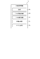
- FIG. 3 is a block diagram showing control functions according to the radio communication control program of the radio communication control device 10.
- the radio communication control apparatus 10 includes a collection unit 10a, a channel evaluation value calculation unit 10b, a channel candidate calculation unit 10c, an interference power It includes a calculator 10d and a channel selector 10e. The operation of each unit will be described later.
- FIG. 4 is a flow chart showing a first example of the optimum channel selection processing procedure by the radio communication control device.
- processing between AP1a of the first wireless communication system and STAs 2-1a, 2-2a, 2-3a, and 2-4a will be described, and unless otherwise specified, the first wireless communication system will simply be referred to as a wireless communication system, AP 1a will simply be referred to as AP, and STAs 2-1a, 2-2a, 2-3a, and 2-4a will simply be referred to as STAs.
- the collection unit 10a of the AP collects scan results, which are the usage statuses of all wireless channel candidates, from all STAs, which are wireless communication devices connected to the AP (s1). Based on sensing information from the STA's GPS sensor 17, when multiple STAs are located near the AP, the AP needs to target all STAs for information collection for control. no.
- the unit channel constituting the radio channel used by the interfering terminals in the vicinity of the radio communication system may be determined by the AP based on the unit channel of the frequency band used by the STA. Assume that it is possible information.
- the channel evaluation value calculation unit 10b calculates the evaluation value of each radio channel that is a candidate for the optimum radio channel, and transmits a signal between the AP and the STA.
- a transmission delay time is calculated (s2).
- the channel evaluation value calculator 10b estimates, for example, the transmission delay time of each channel, and determines that a channel with a relatively short transmission delay time is a channel with relatively many transmission opportunities.
- the evaluation target for estimating the evaluation value is the radio channel width. The center frequency is shifted by the unit channel and evaluated.
- the radio channel to be evaluated is defined as a channel window.
- wireless channels in which the channel windows are shifted by unit channel widths and partially overlapped are evaluated. As a result, it is possible to increase the options of radio channels, and it is possible to select channels more flexibly, which contributes to increasing the communication capacity of the area.
- the transmission delay time is estimated as an evaluation value
- each terminal has an upper limit on the time that can be transmitted. does not necessarily occur immediately.
- modeling using mathematical formulas like queues is possible according to the number of interfering wireless communication devices.
- the transmission delay time is estimated by using the formula modeled as described above and used as the channel evaluation value.
- evaluation targets include the number of interfering cells, the number of observed wireless communication devices, the occupation rate of wireless communication resources, and the like.
- the channel candidate calculation unit 10c calculates the total value obtained by integrating the evaluation values calculated for each STA for each channel. Among them, the channel with the best total evaluation value is selected as the optimum channel candidate (s3). For example, when the above transmission delay times are evaluated, the channel candidate calculator 10c sums up the transmission delay times calculated for each channel, and selects the radio channel with the shortest total time as the result of this summation as the optimum channel. be selected as a candidate for
- the channel selection unit 10e finally selects this candidate as the optimum channel, and the control process ends.
- the channel selection unit 10e when there are multiple candidates for the channel with the best evaluation value selected in s3, that is, the optimal channel (No in s4), one candidate must be finally selected from these candidates.
- the interference power calculation unit 10d calculates the actual interference power of the interfering cell or the interference power for each of the plurality of candidates for the optimum radio channel. is calculated (s5).
- This effective interference power is not the reception strength of the radio wave received from the interfering wireless communication device itself, but the influence exerted on each candidate of the optimum wireless channel is the PER (Packet Error Rate). means a power value that can be converted as noise to the entire wireless channel when compared by using .
- the channel selection unit 10e finally selects the candidate with the smallest interference power value calculated above from among the candidates for the optimum channel as the optimum channel (s6), and the control process ends.
- FIG. 5 is a flow chart showing a second example of the optimum channel selection processing procedure by the radio communication control apparatus.
- the channel evaluation satisfies a certain condition, for example, regarding a BSS, which is a cell composed of APs and STAs
- the transmission delay time calculated for one channel is equal to or less than a certain value. or when the number of interfering BSSs in a channel is less than a certain value, stop collecting scan results and calculating evaluation values for other channels, and select the channel as the optimal channel, thereby controlling This is an example in which the time required for processing can be shortened.
- the collection unit 10a of the AP collects the scan results of one channel selected from among the radio channel candidates from one STA selected from the STAs connected to the AP (s11). .
- the channel evaluation value calculation unit 10b calculates the transmission delay time, which is the evaluation value of each radio channel that is the optimum radio channel candidate (s12).
- This calculated transmission delay satisfies a certain condition, for example, the transmission delay calculated for the selected channel is less than or equal to a certain value, or the number of interfering BSSs on the channel is less than or equal to a certain value.
- the channel selection unit 10e finally selects the selected channel as the optimum channel, and the control process ends.
- the channel candidate calculation unit 10c calculates a total value obtained by integrating the evaluation values calculated for each STA for each channel, and selects the channel with the best total evaluation value among the channels as an optimum channel candidate. (s14). Thereafter, the same processing as s4, s5, and s6 in the first example is performed (s15, s16, s17).
- FIG. 6 is a diagram showing information on interference channels observed by a terminal in tabular form.
- the example shown in FIG. 6 shows a list of interference channel information observed by each STA connected to the AP. Assume that the unit of this interference channel information is dBm.
- the width of the channel window is 1 MHz, which is a frequency bandwidth obtained by bundling five unit channel bandwidths of 200 kHz. .
- the frequency bandwidth of each wireless channel is the frequency bandwidth of five unit channels.
- the radio wave reception intensity is acquired by the collecting unit 10a for each unit channel and recorded in the internal memory of the wireless communication control device 10 or the like.
- FIG. 7 is a diagram showing an example of a channel window for each channel.
- the example shown in FIG. 7 shows a list of channel windows used for collecting scan results and calculating evaluation values as described above.
- the channel window shown in FIG. 7 is a channel window having a width of 1 MHz, which is a frequency bandwidth for five consecutive channels from channel "1" to channel "5", which are unit channels, and channel "2" to channel “6".
- the channel evaluation value calculation unit 10b first calculates the number of interfering BSSs detected by carrier sense when observed in each channel window as follows: is calculated by the formulas (1) and (2). Simultaneous transmissions from multiple interfering BSSs are also possible, but here we assume that all interfering BSSs can carrier sense each other and are transmitted at different timings.
- each parameter in the above formulas (1) and (2) is as follows.
- Mn number of BSSIDs (Basic Service Set Identifiers) of interfering BSSs observed by terminal n
- P(I,k) Power intensity for channel k of interfering BSSID In,m: m-th interfering BSS observed at terminal n
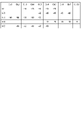
- FIG. 8 is a diagram showing an example of calculation results of the number of interfering BSSs in tabular form.
- P th is “ ⁇ 80 dBm”, in the example shown in FIG. 6, the calculation result of the interfering BSS number for each channel window corresponds to the result shown in FIG.
- the average transmission delay time calculated by queuing theory from the number of interfering BSSs in each channel window can be calculated by the following equations (3) to (6).
- ⁇ in equations (5) and (6) below indicates the utilization rate of the channel.
- ⁇ is greater than 1.0, the channel latency cannot be calculated using a queuing model, so it is assumed that the channel latency increases with the number of interfering BSSs. and the waiting time is calculated.
- the channel utilization can be modeled by calculating the average transmission delay time with d set to 10%.
- the number of terminals in the BSS or the traffic volume of each terminal may be set as an input value, or a value based on information observed or monitored by capturing packets or the like is set as an input value.
- the average transmission delay time calculated by the above queuing model is not proportional to the number of interfering BSSs. Therefore, when the evaluation value is obtained by summing the transmission delay times of a plurality of STAs, if there is even one STA with a clearly large number of interfering BSSs observed in the channel window, transmission on the corresponding channel The delay time becomes significantly longer, resulting in a significantly worse evaluation value.
- FIG. 9 is a diagram illustrating an example of partial interference of radio channels between radio communication systems.
- the desired signal symbol a in FIG. 9
- the interference signal symbol b in FIG. 9
- the destination of the transmission frame (flame) from the STA is Reception quality at some access point devices is an issue.
- the desired signal and the interference signal have received strength fluctuations within the range indicated by symbol c in FIG.
- the reception quality is usually expressed by SINR (Signal to Interference and Noise power ratio) or CIR (Carrier to Interference Ratio).
- SINR Signal to Interference and Noise power ratio
- CIR Carrier to Interference Ratio
- the reception quality is expressed by the difference in the power intensity of the received signal on each radio channel.
- partial interference for example, shown in FIG. 9 occurs, which is the object of this embodiment, the effect cannot be represented by the difference in received power intensity.
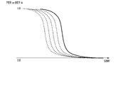
- the influence of interference is defined as PER or BER (Bit Error Rate), and the SINR value with the same PER or BER is the actual SINR.
- FIG. 10 is a diagram illustrating an example of mapping from PER or BER to SINR. Existing data is used for the mapping from PER or BER to SINR. It should be noted that data in which the desired signal and the interference signal of the radio channel are completely overlapped is used as the existing data.
- the interference power calculated from the real SINR is the real interference power.
- This net interference power can be calculated as the power strength of received signals from APs interfering with the system minus the SINR difference at the time of partial interference.
- this real interference power may be calculated as a value shifted by a certain value from the existing data based on experimental results obtained in advance, for example, as a difference in SINR at the time of partial interference. It may be mapped in terms of points.
- the range of this fluctuation is the margin value (There are also methods in which the influence of interference is estimated after the received power measured as margin value) is corrected.
- the net interference power for one radio channel is calculated for all interfering terminals, and the sum of the calculated values for each terminal is the net interference power for other radio channels. If it is small compared to the power, it can be determined that the radio channel is less affected by interference.
- each embodiment can be applied to a program (software means) that can be executed by a computer (computer), for example, a magnetic disk (floppy disk, hard disk) etc.), optical discs (CD-ROM, DVD, MO, etc.), semiconductor memory (ROM, RAM, flash memory, etc.) and other recording media, or transmitted and distributed via communication media can be
- the programs stored on the medium also include a setting program for configuring software means (including not only execution programs but also tables and data structures) to be executed by the computer.
- a computer that realizes this device reads a program recorded on a recording medium, and optionally constructs software means by a setting program, and executes the above-described processing by controlling the operation by this software means.
- the term "recording medium” as used herein is not limited to those for distribution, and includes storage media such as magnetic disks, semiconductor memories, etc. provided in computers or devices connected via a network.
- the present invention is not limited to the above-described embodiments, and can be variously modified in the implementation stage without departing from the gist of the present invention. Further, each embodiment may be implemented in combination as appropriate, in which case the combined effect can be obtained. Furthermore, various inventions are included in the above embodiments, and various inventions can be extracted by combinations selected from a plurality of disclosed constituent elements. For example, even if some constituent elements are deleted from all the constituent elements shown in the embodiments, if the problem can be solved and effects can be obtained, the configuration with the constituent elements deleted can be extracted as an invention.
Landscapes
- Engineering & Computer Science (AREA)
- Computer Networks & Wireless Communication (AREA)
- Signal Processing (AREA)
- Quality & Reliability (AREA)
- Mobile Radio Communication Systems (AREA)
Priority Applications (2)
| Application Number | Priority Date | Filing Date | Title |
|---|---|---|---|
| JP2023528846A JP7677417B2 (ja) | 2021-06-16 | 2021-06-16 | 無線通信システム、無線通信方法、無線通信制御装置およびプログラム |
| PCT/JP2021/022895 WO2022264320A1 (ja) | 2021-06-16 | 2021-06-16 | 無線通信システム、無線通信方法、無線通信制御装置およびプログラム |
Applications Claiming Priority (1)
| Application Number | Priority Date | Filing Date | Title |
|---|---|---|---|
| PCT/JP2021/022895 WO2022264320A1 (ja) | 2021-06-16 | 2021-06-16 | 無線通信システム、無線通信方法、無線通信制御装置およびプログラム |
Publications (1)
| Publication Number | Publication Date |
|---|---|
| WO2022264320A1 true WO2022264320A1 (ja) | 2022-12-22 |
Family
ID=84526467
Family Applications (1)
| Application Number | Title | Priority Date | Filing Date |
|---|---|---|---|
| PCT/JP2021/022895 Ceased WO2022264320A1 (ja) | 2021-06-16 | 2021-06-16 | 無線通信システム、無線通信方法、無線通信制御装置およびプログラム |
Country Status (2)
| Country | Link |
|---|---|
| JP (1) | JP7677417B2 (https=) |
| WO (1) | WO2022264320A1 (https=) |
Cited By (1)
| Publication number | Priority date | Publication date | Assignee | Title |
|---|---|---|---|---|
| WO2024247278A1 (ja) * | 2023-06-02 | 2024-12-05 | 日本電信電話株式会社 | 無線通信システム、無線基地局、無線通信方法、及びプログラム |
Citations (3)
| Publication number | Priority date | Publication date | Assignee | Title |
|---|---|---|---|---|
| JP2003078532A (ja) * | 2001-09-03 | 2003-03-14 | Ntt Docomo Inc | 送信制御方法、通信システム、通信装置および通信端末 |
| JP2006504356A (ja) * | 2002-11-04 | 2006-02-02 | テルコーディア テクノロジーズ インコーポレイテッド | リアルタイムにセルラーネットワークを構成する方法及びシステム |
| JP2016076887A (ja) * | 2014-10-08 | 2016-05-12 | 日本電信電話株式会社 | 無線通信システム、移動通信基地局、無線端末装置及び無線通信方法 |
Family Cites Families (3)
| Publication number | Priority date | Publication date | Assignee | Title |
|---|---|---|---|---|
| JP2007221178A (ja) | 2005-04-01 | 2007-08-30 | Ntt Docomo Inc | 送信装置及び送信方法 |
| JP2007259358A (ja) | 2006-03-24 | 2007-10-04 | Toshiba Corp | 無線通信システムとその無線通信端末 |
| JP2007259346A (ja) | 2006-03-24 | 2007-10-04 | Toshiba Corp | 無線通信システムとその無線通信端末 |
-
2021
- 2021-06-16 WO PCT/JP2021/022895 patent/WO2022264320A1/ja not_active Ceased
- 2021-06-16 JP JP2023528846A patent/JP7677417B2/ja active Active
Patent Citations (3)
| Publication number | Priority date | Publication date | Assignee | Title |
|---|---|---|---|---|
| JP2003078532A (ja) * | 2001-09-03 | 2003-03-14 | Ntt Docomo Inc | 送信制御方法、通信システム、通信装置および通信端末 |
| JP2006504356A (ja) * | 2002-11-04 | 2006-02-02 | テルコーディア テクノロジーズ インコーポレイテッド | リアルタイムにセルラーネットワークを構成する方法及びシステム |
| JP2016076887A (ja) * | 2014-10-08 | 2016-05-12 | 日本電信電話株式会社 | 無線通信システム、移動通信基地局、無線端末装置及び無線通信方法 |
Cited By (1)
| Publication number | Priority date | Publication date | Assignee | Title |
|---|---|---|---|---|
| WO2024247278A1 (ja) * | 2023-06-02 | 2024-12-05 | 日本電信電話株式会社 | 無線通信システム、無線基地局、無線通信方法、及びプログラム |
Also Published As
| Publication number | Publication date |
|---|---|
| JPWO2022264320A1 (https=) | 2022-12-22 |
| JP7677417B2 (ja) | 2025-05-15 |
Similar Documents
| Publication | Publication Date | Title |
|---|---|---|
| CN101803417B (zh) | 在无线网络中选择更宽带宽信道 | |
| KR101571904B1 (ko) | 이동통신 시스템에서 마이크로 단말에게 주파수 자원을 할당하기 위한 장치 및 방법 | |
| JP5150153B2 (ja) | 資源割当装置、集中制御装置、無線基地局、無線通信システム、資源割当方法及び資源割当プログラム | |
| KR102166093B1 (ko) | 무선통신시스템에서 액세스 포인트 연결장치 및 방법 | |
| EP3646633B1 (en) | Radio sensor coverage estimation for wireless network assurance | |
| JP2010516190A (ja) | 無線基地局における干渉を測定する方法および装置 | |
| CN102273306A (zh) | 基于来自另一基站的干扰指示符信息调度基站数据传输 | |
| CN113691333B (zh) | 通信信道优化方法和装置、电子设备、存储介质 | |
| US10887774B2 (en) | Mobile communications system expansion method and device, storage medium, and program product | |
| JP2021535686A (ja) | 干渉源識別方法、関連デバイス、およびコンピュータ記憶媒体 | |
| EP3053389B1 (en) | Controlling uplink transmissions from interfering stations | |
| KR101388557B1 (ko) | 채널 선택 시스템 및 방법, 그 ap, 이를 위한 기록매체 | |
| WO2022264320A1 (ja) | 無線通信システム、無線通信方法、無線通信制御装置およびプログラム | |
| JP5360207B2 (ja) | 基地局装置、エッジユーザ推定方法及びプログラム | |
| JP6891631B2 (ja) | 通信装置、制御装置、通信システム、通信方法、および通信制御用プログラム | |
| JP7298773B2 (ja) | 無線通信システム、無線通信制御装置および方法 | |
| CN116781190A (zh) | 用于在信标间隔期间在接入点之间进行测距的信道分配 | |
| Chen et al. | Select: Self-learning collision avoidance for wireless networks | |
| US20170005898A1 (en) | Distributed saturation detection method for wireless network nodes | |
| EP3391590B1 (en) | Noise floor degradation detection for co-located radios | |
| CN113938956B (zh) | 资源分配方法、装置及计算机可读存储介质 | |
| KR20120097275A (ko) | 무선 ap에서 자동으로 간섭을 인지하고 회피하는 운용 방법 및 장치 | |
| CN116234026A (zh) | 网络减频方法、装置及可读存储介质 | |
| Phan et al. | Packet loss priority of cognitive radio networks with partial buffer sharing | |
| JP2025500708A5 (https=) |
Legal Events
| Date | Code | Title | Description |
|---|---|---|---|
| 121 | Ep: the epo has been informed by wipo that ep was designated in this application |
Ref document number: 21945997 Country of ref document: EP Kind code of ref document: A1 |
|
| WWE | Wipo information: entry into national phase |
Ref document number: 2023528846 Country of ref document: JP |
|
| NENP | Non-entry into the national phase |
Ref country code: DE |
|
| 122 | Ep: pct application non-entry in european phase |
Ref document number: 21945997 Country of ref document: EP Kind code of ref document: A1 |