WO2022264320A1 - Wireless communication system, wireless communication method, wireless communication control device, and program - Google Patents
Wireless communication system, wireless communication method, wireless communication control device, and program Download PDFInfo
- Publication number
- WO2022264320A1 WO2022264320A1 PCT/JP2021/022895 JP2021022895W WO2022264320A1 WO 2022264320 A1 WO2022264320 A1 WO 2022264320A1 JP 2021022895 W JP2021022895 W JP 2021022895W WO 2022264320 A1 WO2022264320 A1 WO 2022264320A1
- Authority
- WO
- WIPO (PCT)
- Prior art keywords
- wireless communication
- radio frequency
- radio
- channel
- frequency channel
- Prior art date
Links
- 238000004891 communication Methods 0.000 title claims abstract description 167
- 238000000034 method Methods 0.000 title claims description 19
- 238000011156 evaluation Methods 0.000 claims abstract description 46
- 230000005540 biological transmission Effects 0.000 claims description 36
- 230000008054 signal transmission Effects 0.000 claims 1
- 230000002452 interceptive effect Effects 0.000 description 29
- 238000010586 diagram Methods 0.000 description 16
- VYLDEYYOISNGST-UHFFFAOYSA-N bissulfosuccinimidyl suberate Chemical compound O=C1C(S(=O)(=O)O)CC(=O)N1OC(=O)CCCCCCC(=O)ON1C(=O)C(S(O)(=O)=O)CC1=O VYLDEYYOISNGST-UHFFFAOYSA-N 0.000 description 13
- 230000015654 memory Effects 0.000 description 8
- 238000012545 processing Methods 0.000 description 8
- 230000006870 function Effects 0.000 description 6
- 239000000470 constituent Substances 0.000 description 4
- 238000013507 mapping Methods 0.000 description 3
- 230000000694 effects Effects 0.000 description 2
- 239000004065 semiconductor Substances 0.000 description 2
- 230000006399 behavior Effects 0.000 description 1
- 230000002301 combined effect Effects 0.000 description 1
- 238000005516 engineering process Methods 0.000 description 1
- 230000003287 optical effect Effects 0.000 description 1
- 230000007704 transition Effects 0.000 description 1
Images


Classifications
-
- H—ELECTRICITY
- H04—ELECTRIC COMMUNICATION TECHNIQUE
- H04W—WIRELESS COMMUNICATION NETWORKS
- H04W16/00—Network planning, e.g. coverage or traffic planning tools; Network deployment, e.g. resource partitioning or cells structures
- H04W16/02—Resource partitioning among network components, e.g. reuse partitioning
- H04W16/10—Dynamic resource partitioning
-
- H—ELECTRICITY
- H04—ELECTRIC COMMUNICATION TECHNIQUE
- H04W—WIRELESS COMMUNICATION NETWORKS
- H04W16/00—Network planning, e.g. coverage or traffic planning tools; Network deployment, e.g. resource partitioning or cells structures
- H04W16/14—Spectrum sharing arrangements between different networks
-
- H—ELECTRICITY
- H04—ELECTRIC COMMUNICATION TECHNIQUE
- H04W—WIRELESS COMMUNICATION NETWORKS
- H04W28/00—Network traffic management; Network resource management
- H04W28/16—Central resource management; Negotiation of resources or communication parameters, e.g. negotiating bandwidth or QoS [Quality of Service]
-
- H—ELECTRICITY
- H04—ELECTRIC COMMUNICATION TECHNIQUE
- H04W—WIRELESS COMMUNICATION NETWORKS
- H04W84/00—Network topologies
- H04W84/02—Hierarchically pre-organised networks, e.g. paging networks, cellular networks, WLAN [Wireless Local Area Network] or WLL [Wireless Local Loop]
- H04W84/10—Small scale networks; Flat hierarchical networks
- H04W84/12—WLAN [Wireless Local Area Networks]
-
- Y—GENERAL TAGGING OF NEW TECHNOLOGICAL DEVELOPMENTS; GENERAL TAGGING OF CROSS-SECTIONAL TECHNOLOGIES SPANNING OVER SEVERAL SECTIONS OF THE IPC; TECHNICAL SUBJECTS COVERED BY FORMER USPC CROSS-REFERENCE ART COLLECTIONS [XRACs] AND DIGESTS
- Y02—TECHNOLOGIES OR APPLICATIONS FOR MITIGATION OR ADAPTATION AGAINST CLIMATE CHANGE
- Y02D—CLIMATE CHANGE MITIGATION TECHNOLOGIES IN INFORMATION AND COMMUNICATION TECHNOLOGIES [ICT], I.E. INFORMATION AND COMMUNICATION TECHNOLOGIES AIMING AT THE REDUCTION OF THEIR OWN ENERGY USE
- Y02D30/00—Reducing energy consumption in communication networks
- Y02D30/70—Reducing energy consumption in communication networks in wireless communication networks
Abstract
In a wireless communication system according to an embodiment, an access point device, a plurality of station devices and a wireless communication control device perform wireless communications. The wireless communication control device comprises: a collection unit that collects information indicating the use condition of each of a plurality of radio frequency channels used for the wireless communications between the access point device and the station devices; a calculating unit that calculates, on the basis of the information collected by the collection unit, an evaluation value, which is related to the selection of an optimum radio frequency channel for the wireless communications, for each of the plurality of radio frequency channels; and a selecting unit that selects, on the basis of the evaluation values calculated by the calculation unit, one of the plurality of radio frequency channels that is at the optimum for the wireless communications.
Description
本発明の実施形態は、無線通信システム、無線通信方法、無線通信制御装置およびプログラムに関する。
Embodiments of the present invention relate to a wireless communication system, a wireless communication method, a wireless communication control device, and a program.
基地局および端末により構成される無線通信システム(wireless communication system)が知られている。
無線通信システムの代表的な例として、公衆用途の無線LAN(Local area network)が挙げられる。公衆用途の無線LANでは、例えば、基地局から公衆のコンピュータ(computer)端末およびスマートフォン(smart phone)端末に対してデータ(data)が送信されるユースケース(use-case)が想定される。
さらに、近年のIoT(Internet of Things)端末の普及から、端末側からデータを送信するユースケースが増えている。 A wireless communication system comprising base stations and terminals is known.
A typical example of a wireless communication system is a wireless LAN (Local Area Network) for public use. In wireless LANs for public use, for example, a use-case in which data is transmitted from a base station to public computer terminals and smart phone terminals is assumed.
Furthermore, with the spread of IoT (Internet of Things) terminals in recent years, the number of use cases in which data is transmitted from the terminal side is increasing.
これら端末の普及と利用可能な周波数帯の制限とから、無線チャネル(channel)(無線周波数チャネル、または単にチャネルと称されることがある。)が完全に分離された配置にして、各チャネルが各無線通信システムに割り当てられるのみでは、複数の無線通信システム間(単に、システム間と称されることがある。)で互いに電波信号が干渉を及ぼして通信範囲であるエリア(area)全体の通信容量が低下する恐れがある。
特に上記周波数帯は限られているため、エリアの通信容量が最大化されるために、可能な限り効率的にチャネルが配置される必要がある。 Due to the spread of these terminals and the limitation of available frequency bands, radio channels (channels) (sometimes called radio frequency channels, or simply channels) are completely separated, and each channel is Only by assigning to each wireless communication system, radio signals interfere with each other between a plurality of wireless communication systems (sometimes simply called inter-system) Communication over the entire area, which is the communication range Capacity may decrease.
Especially since the frequency band is limited, the channels need to be arranged as efficiently as possible in order to maximize the communication capacity of the area.
チャネルの配置にあたり、周波数に対して、他の無線通信システムとの間で排他的なチャネル設定では、利用できるチャネルの選択肢が限られているため、互いに干渉する無線通信システムの数が多くなる。その結果、結果的にエリアの通信容量が低下してしまう。
他方で、チャネル配置の選択肢を周波数に対して排他的にせずに、複数の無線通信システムの間で部分的に干渉させる方法では、システム間で電波信号が互いに干渉しつつも干渉電力を抑えられ、チャネルの選択肢も増える。すなわち、システム間でチャネルを部分的に適切に干渉させることで、エリアの通信容量の改善に寄与する。 When arranging channels, exclusive channel setting with respect to frequency with other radio communication systems limits available channel options, resulting in a large number of radio communication systems interfering with each other. As a result, the communication capacity of the area is reduced as a result.
On the other hand, in the method of partially interfering between multiple wireless communication systems without making channel allocation options exclusive to frequency, interference power can be suppressed while radio signals interfere with each other between systems. , more channel options. In other words, it contributes to the improvement of the communication capacity of the area by causing the channels to partially interfere appropriately between the systems.
また、920MHz帯のようにduty比(送信時間制限)が定められている周波数帯では、システム間で電波信号の周波数帯が同じチャネルで共存していても、電波信号の送信タイミング(timing)が限られるため衝突確率は低いため、エリアの通信容量には影響しない。
このように、システム間での周波数帯の干渉割合および送信時間の比率が勘案されることで、当該周波数帯で適切なチャネル配置が可能になると考えられる。 Also, in a frequency band such as the 920 MHz band, where the duty ratio (transmission time limit) is defined, even if the frequency bands of radio signals coexist in the same channel between systems, the timing of transmitting radio signals is different. Since the collision probability is low due to the limited number, it does not affect the communication capacity of the area.
In this way, by taking into account the frequency band interference ratio and the transmission time ratio between systems, it is considered possible to appropriately allocate channels in the frequency band.
上記システム間で無線チャネルの部分的な干渉が発生する周波数帯において、かつ周辺の干渉端末の送信時間に上限がある場合、端末の通信容量を最大化するためには適切なチャネル選択が必要になる。
In frequency bands where partial radio channel interference occurs between the above systems, and when there is an upper limit to the transmission time of nearby interfering terminals, it is necessary to select appropriate channels in order to maximize the communication capacity of terminals. Become.
この発明は、上記事情に着目してなされたもので、その目的とするところは、無線信号の最適な共存周波数を求めることができるようにした無線通信システム、無線通信方法、無線通信制御装置およびプログラムを提供することにある。
The present invention has been made in view of the above circumstances, and aims to provide a radio communication system, a radio communication method, a radio communication control apparatus, and a radio communication control apparatus, which are capable of obtaining the optimum coexistence frequency of radio signals. to provide the program.
本発明の一態様に係る無線通信システムは、アクセスポイント装置と複数のステーション装置と無線通信制御装置とが無線通信を行なう無線通信システムであって、前記無線通信制御装置は、前記アクセスポイント装置と前記ステーション装置との間の無線通信に用いられる複数の無線周波数チャネルの各々の使用状況を示す情報を収集する収集部と、前記収集部により収集された情報に基づいて、前記複数の無線周波数チャネルの各々について、前記無線通信に最適な無線周波数チャネルの選択に係る評価値を計算する計算部と、前記計算部により計算された評価値に基づいて、前記複数の無線周波数チャネルのうち、前記無線通信に最適な無線周波数チャネルを選択する選択部と、を備える。
A wireless communication system according to an aspect of the present invention is a wireless communication system in which an access point device, a plurality of station devices, and a wireless communication control device perform wireless communication, wherein the wireless communication control device communicates with the access point device. a collection unit for collecting information indicating usage status of each of a plurality of radio frequency channels used for wireless communication with the station device; and based on the information collected by the collection unit, the plurality of radio frequency channels. for each of the plurality of radio frequency channels, based on the evaluation value calculated by the calculation unit for calculating the evaluation value related to the selection of the optimum radio frequency channel for the radio communication, the radio among the plurality of radio frequency channels a selection unit for selecting the best radio frequency channel for communication.
本発明の一態様に係る無線通信方法は、アクセスポイント装置と複数のステーション装置とが無線通信を行ない、前記無線通信が無線通信制御装置により制御される無線通信方法であって、前記無線通信制御装置により、前記アクセスポイント装置と前記ステーション装置との間の無線通信に用いられる複数の無線周波数チャネルの各々の使用状況を示す情報を収集することと、前記収集された情報に基づいて、前記複数の無線周波数チャネルの各々について、前記無線通信に最適な無線周波数チャネルの選択に係る評価値を計算することと、前記計算された評価値に基づいて、前記複数の無線周波数チャネルのうち、前記無線通信に最適な無線周波数チャネルを選択することと、を備える。
A wireless communication method according to an aspect of the present invention is a wireless communication method in which an access point device and a plurality of station devices perform wireless communication, and the wireless communication is controlled by a wireless communication control device, wherein the wireless communication control collecting, by a device, information indicating usage status of each of a plurality of radio frequency channels used for wireless communication between the access point device and the station device; calculating an evaluation value relating to selection of an optimum radio frequency channel for wireless communication for each of the radio frequency channels; and based on the calculated evaluation value, among the plurality of radio frequency channels, the radio selecting the best radio frequency channel for communication.
本発明の一態様に係る無線通信制御装置は、アクセスポイント装置と複数のステーション装置と無線通信を行なう無線通信システムの無線通信制御装置であって、前記アクセスポイント装置と前記ステーション装置との間の無線通信に用いられる複数の無線周波数チャネルの各々の使用状況を示す情報を収集する収集部と、前記収集部により収集された情報に基づいて、前記複数の無線周波数チャネルの各々について、前記無線通信に最適な無線周波数チャネルの選択に係る評価値を計算する計算部と、前記計算部により計算された評価値に基づいて、前記複数の無線周波数チャネルのうち、前記無線通信に最適な無線周波数チャネルを選択する選択部と、を備える。
A radio communication control device according to one aspect of the present invention is a radio communication control device of a radio communication system that performs radio communication with an access point device and a plurality of station devices, wherein a collection unit for collecting information indicating usage status of each of a plurality of radio frequency channels used for wireless communication; and the radio communication for each of the plurality of radio frequency channels based on the information collected by the collection unit. a calculation unit for calculating an evaluation value related to selection of an optimum radio frequency channel for radio communication; and a selection unit that selects the
本発明によれば、無線信号の最適な共存周波数を求めることができる。
According to the present invention, the optimum coexistence frequency of radio signals can be obtained.
以下、この発明に関わる一実施形態の無線通信システム、無線通信方法、アクセスポイント(access point)装置およびプログラムについて、図面を参照して説明する。
本実施形態では、周波数帯で通信する際の通信容量が最大化される無線チャネルが選択されるために、送信機会が最も獲得され得る無線チャネルと、送信された際に誤りが少なく最も速い伝送レート(transmission rate)での送信が可能である無線チャネルとが推定される。
なお、本実施形態では、無線通信システムの周辺に、既に無線チャネルが決定している、およびシステムに干渉を及ぼす端末が存在する条件で、無線チャネルが選択される。 A wireless communication system, a wireless communication method, an access point device, and a program according to one embodiment of the present invention will be described below with reference to the drawings.
In this embodiment, since the radio channel that maximizes the communication capacity when communicating in the frequency band is selected, the radio channel that can obtain the most transmission opportunity and the fastest transmission with few errors when transmitted are selected. A radio channel is estimated that allows transmission at a transmission rate.
In this embodiment, a radio channel is selected under the condition that a radio channel has already been determined and a terminal interfering with the system exists in the vicinity of the radio communication system.
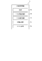
図1は、本発明の一実施形態に係る無線通信システムの全体の構成例を示すブロック図である。
図1に示される例では、本実施形態に係る無線通信システムは、第1のエリアaを無線LANの親機であるAP(アクセスポイント装置)と無線LANの子機である複数のSTA(ステーション(station)装置)との間の通信範囲とする第1の無線通信システムと、第2のエリアbを上記通信範囲とする第2の無線通信システムとが示される。APとSTAは、あわせて無線通信装置と称されることがある。 FIG. 1 is a block diagram showing an overall configuration example of a radio communication system according to one embodiment of the present invention.
In the example shown in FIG. 1, the wireless communication system according to the present embodiment defines a first area a as a wireless LAN parent device (AP (access point device)) and a plurality of wireless LAN slave devices (STAs (stations). (station) apparatus), and a second wireless communication system having a second area b as the communication range. APs and STAs are sometimes collectively referred to as wireless communication devices.
第1の無線通信システムでは、AP1aと、複数のSTA2-1a,2-2a,2-3a,および2-4aとを有し、AP1aに対して、上記複数のSTA2-1a,2-2a,2-3a,および2-4aが接続されて通信が行われる。なお、STAの台数は特に限られない。
A first wireless communication system has an AP1a and a plurality of STAs 2-1a, 2-2a, 2-3a, and 2-4a. 2-3a and 2-4a are connected for communication. Note that the number of STAs is not particularly limited.
第2の無線通信システムでは、AP1bと、複数のSTA2-1b,2-2b,2-3b,および2-4bとを有し、AP1bに対して、上記複数のSTA2-1b,2-2b,2-3b,および2-4bが接続されて通信が行われる。
The second wireless communication system has an AP1b and a plurality of STAs 2-1b, 2-2b, 2-3b, and 2-4b, and for AP1b, the plurality of STAs 2-1b, 2-2b, 2-2b, 2-3b and 2-4b are connected for communication.
ここで、AP1aとSTA2-1a,2-2a,2-3a,および2-4aとで構成されるセル(cell)は、BSS(Basic Service Set)と呼ばれる。AP1bとSTA2-1b,2-2b,2-3b,および2-4bとで構成されるセルも同様である。
Here, a cell composed of AP1a and STAs 2-1a, 2-2a, 2-3a, and 2-4a is called a BSS (Basic Service Set). The same applies to a cell composed of AP1b and STAs 2-1b, 2-2b, 2-3b, and 2-4b.
また、AP1aには、無線通信制御装置10が有線または無線の通信ネットワーク(communication network)で接続される。この無線通信制御装置10は、無線環境情報および制御情報を交換する機能を有する。
Also, the wireless communication control device 10 is connected to the AP1a via a wired or wireless communication network. This radio communication control device 10 has a function of exchanging radio environment information and control information.
このAP1aに接続される無線通信制御装置10は、その無線通信制御プログラムがAP1aの中に搭載されるときは、AP1aの外部機器として当該AP1aに接続される必要はない。
また、STAが比較的高機能な装置であり、かつSTAが有する演算機能に比較的余裕がある場合は、APではなくSTAに対して無線通信制御装置およびその無線通信制御プログラムが搭載されていてもよい。 The wirelesscommunication control device 10 connected to this AP1a need not be connected to the AP1a as an external device of the AP1a when the wireless communication control program is installed in the AP1a.
In addition, if the STA is a relatively sophisticated device and has a relatively large amount of computational capability, the wireless communication control device and its wireless communication control program are installed in the STA instead of the AP. good too.
また、STAが比較的高機能な装置であり、かつSTAが有する演算機能に比較的余裕がある場合は、APではなくSTAに対して無線通信制御装置およびその無線通信制御プログラムが搭載されていてもよい。 The wireless
In addition, if the STA is a relatively sophisticated device and has a relatively large amount of computational capability, the wireless communication control device and its wireless communication control program are installed in the STA instead of the AP. good too.
図1に示された例では、第1の無線通信システムに対する干渉端末として、上記第2の無線通信システムのAP1bと、このAP1bに接続されるSTA2-1b,2-2b,2-3b,および2-4bが存在する。ここでは、これらのAP1bおよびSTA2-1b,2-2b,2-3b,および2-4bは、特定の同一の無線チャネルが用いられて、既に通信していると仮定する。
In the example shown in FIG. 1, as interfering terminals for the first wireless communication system, AP1b of the second wireless communication system, STAs 2-1b, 2-2b, 2-3b connected to this AP1b, and 2-4b are present. Here, it is assumed that these AP1b and STAs 2-1b, 2-2b, 2-3b, and 2-4b are already communicating using the same specific radio channel.
AP1aおよびSTA2-1a,2-2a,2-3a,および2-4aも、既に無線で接続されて通信できる状態であるが、本実施形態では、最適な無線チャネルを選択することができる。なお、これらSTAにより使用される無線チャネルは、所定の周波数帯で規定される一つないし複数の単位チャネルが束ねられて使用される。
AP1a and STAs 2-1a, 2-2a, 2-3a, and 2-4a are already wirelessly connected and ready for communication, but in this embodiment, the optimum wireless channel can be selected. The wireless channels used by these STAs are bundled together of one or more unit channels defined by a predetermined frequency band.
また、全てのSTAは、常にトラヒック(traffic)を有する無線通信装置である必要はなく、STAには、チャネルのスキャン(scan)および監視などの、無線環境の情報収集を目的に配置される無線通信端末が含まれてもよい。
In addition, all STAs do not need to be wireless communication devices with traffic all the time. A communication terminal may be included.
図2は、無線通信システムにおける無線通信制御装置10のハードウエアの構成例を示すブロック図である。
無線通信制御装置10は、制御回路(processor)11を備える。
制御回路11には、システムおよびデータバス(data bus)を介して、フラッシュROM(flash ROM)などのメモリ(memory)12、磁気ディスク(magnetic disk)などの記憶媒体13aを含むハードディスクドライブ(hard disk drive)13、ユーザ(user)が外部から操作するためのキー(key)、スイッチ(switch)、および外部入力端子を含むユーザインターフェイス(user interface)14、外部との通信を行なうための有線通信モジュール(wired communication module)15または(および)無線通信モジュール(wireless communication module)16、位置を計測するGPSセンサ(Global Positioning System sensor)17、およびチャネルがスキャン(scan)される時間、すなわちチャネルの遷移時間を管理するタイマ(timer)18などが接続される。 FIG. 2 is a block diagram showing a hardware configuration example of the radiocommunication control device 10 in the radio communication system.
The radiocommunication control device 10 includes a control circuit (processor) 11 .
Thecontrol circuit 11 includes a memory 12 such as a flash ROM and a hard disk drive including a storage medium 13a such as a magnetic disk via a system and data bus. 13, a user interface 14 including keys, switches, and external input terminals for external operation by the user, and a wired communication module for communicating with the outside. a wired communication module 15 or/and a wireless communication module 16, a GPS sensor (Global Positioning System sensor) 17 for measuring position, and the time during which channels are scanned, i.e. channel transition times. A timer 18 or the like for managing the is connected.
無線通信制御装置10は、制御回路(processor)11を備える。
制御回路11には、システムおよびデータバス(data bus)を介して、フラッシュROM(flash ROM)などのメモリ(memory)12、磁気ディスク(magnetic disk)などの記憶媒体13aを含むハードディスクドライブ(hard disk drive)13、ユーザ(user)が外部から操作するためのキー(key)、スイッチ(switch)、および外部入力端子を含むユーザインターフェイス(user interface)14、外部との通信を行なうための有線通信モジュール(wired communication module)15または(および)無線通信モジュール(wireless communication module)16、位置を計測するGPSセンサ(Global Positioning System sensor)17、およびチャネルがスキャン(scan)される時間、すなわちチャネルの遷移時間を管理するタイマ(timer)18などが接続される。 FIG. 2 is a block diagram showing a hardware configuration example of the radio
The radio
The
制御回路11は、メモリ12の制御プログラムエリア12aに記憶された無線通信制御プログラムに従い、同メモリ12の管理情報エリア12bに記憶され、または読み出される管理情報に基づき、無線通信制御装置10の各部の動作を制御する。
The control circuit 11 controls each section of the wireless communication control device 10 according to the wireless communication control program stored in the control program area 12a of the memory 12, and based on the management information stored in or read out from the management information area 12b of the memory 12. control behavior.
なお、AP1a、STA2-1a,2-2a,2-3a,および2-4aも、基本的に、図2に示されるAP1aの無線通信制御装置10と同様に、制御回路、メモリ、ユーザインターフェイス、有線通信モジュールまたは(および)無線通信モジュールなどを含むハードウエアにより構成される。
Note that AP1a, STAs 2-1a, 2-2a, 2-3a, and 2-4a are basically similar to the radio communication control device 10 of AP1a shown in FIG. It is composed of hardware including a wired communication module and/or a wireless communication module.
そして、AP1aの無線通信制御装置10が有する無線通信制御プログラムがAP1aの中に搭載される場合は、同無線通信制御プログラムは、例えば、当該AP1a内のメモリの制御プログラムエリアに予め記憶された当該AP(アクセスポイント装置)1aとしての所定の動作を実行するためのAP制御プログラムと共に記憶されてよい。この場合、AP1aは、単独で無線通信制御装置10の機能を併せ持つことになる。
When the wireless communication control program possessed by the wireless communication control device 10 of the AP 1a is installed in the AP 1a, the wireless communication control program is stored in advance in the control program area of the memory in the AP 1a. It may be stored together with an AP control program for executing a predetermined operation as AP (access point device) 1a. In this case, the AP 1a also has the function of the wireless communication control device 10 by itself.
図3は、無線通信制御装置10の無線通信制御プログラムに従った制御機能を示すブロック図である。
図3に示されるように、無線通信制御装置10は、その無線通信制御プログラムに従い制御回路11により実行される機能として、収集部10a、チャネル評価値計算部10b、チャネル候補計算部10c、干渉電力計算部10d、およびチャネル選択部10eを含む。各部の動作については後述する。 FIG. 3 is a block diagram showing control functions according to the radio communication control program of the radiocommunication control device 10. As shown in FIG.
As shown in FIG. 3, the radiocommunication control apparatus 10 includes a collection unit 10a, a channel evaluation value calculation unit 10b, a channel candidate calculation unit 10c, an interference power It includes a calculator 10d and a channel selector 10e. The operation of each unit will be described later.
図3に示されるように、無線通信制御装置10は、その無線通信制御プログラムに従い制御回路11により実行される機能として、収集部10a、チャネル評価値計算部10b、チャネル候補計算部10c、干渉電力計算部10d、およびチャネル選択部10eを含む。各部の動作については後述する。 FIG. 3 is a block diagram showing control functions according to the radio communication control program of the radio
As shown in FIG. 3, the radio
次に、実施形態の無線通信システムの動作について説明する。
図4は、無線通信制御装置による最適なチャネル選択の処理手順の第1の例を示すフローチャートである。ここでは、第1の無線通信システムのAP1aと、STA2-1a,2-2a,2-3a,および2-4aとの間の処理について説明し、特に説明が無い限り、第1の無線通信システムを単に無線通信システムと称し、AP1aを単にAPと称し、STA2-1a,2-2a,2-3a,および2-4aを単にSTAと称して説明する。 Next, operations of the wireless communication system according to the embodiment will be described.
FIG. 4 is a flow chart showing a first example of the optimum channel selection processing procedure by the radio communication control device. Here, processing between AP1a of the first wireless communication system and STAs 2-1a, 2-2a, 2-3a, and 2-4a will be described, and unless otherwise specified, the first wireless communication system will simply be referred to as a wireless communication system,AP 1a will simply be referred to as AP, and STAs 2-1a, 2-2a, 2-3a, and 2-4a will simply be referred to as STAs.
図4は、無線通信制御装置による最適なチャネル選択の処理手順の第1の例を示すフローチャートである。ここでは、第1の無線通信システムのAP1aと、STA2-1a,2-2a,2-3a,および2-4aとの間の処理について説明し、特に説明が無い限り、第1の無線通信システムを単に無線通信システムと称し、AP1aを単にAPと称し、STA2-1a,2-2a,2-3a,および2-4aを単にSTAと称して説明する。 Next, operations of the wireless communication system according to the embodiment will be described.
FIG. 4 is a flow chart showing a first example of the optimum channel selection processing procedure by the radio communication control device. Here, processing between AP1a of the first wireless communication system and STAs 2-1a, 2-2a, 2-3a, and 2-4a will be described, and unless otherwise specified, the first wireless communication system will simply be referred to as a wireless communication system,
まず、APの収集部10aは、APに接続された全ての無線通信装置であるSTAから、無線チャネルの全ての候補の使用状況であるスキャン結果を収集する(s1)。
APは、STAのGPSセンサ17によるセンシング情報(sensing information)をもとに、APから近い位置に複数のSTAが位置するときは、全てのSTAを、制御のための情報収集の対象とする必要はない。
ここで、上記スキャン結果は、STAが使用している周波数帯の単位チャネルに基づき、無線通信システムの周辺の干渉端末に使用されている無線チャネルを構成する単位チャネルがAPにより判定されることが可能な情報であるとする。 First, thecollection unit 10a of the AP collects scan results, which are the usage statuses of all wireless channel candidates, from all STAs, which are wireless communication devices connected to the AP (s1).
Based on sensing information from the STA's GPS sensor 17, when multiple STAs are located near the AP, the AP needs to target all STAs for information collection for control. no.
Here, based on the above scan result, the unit channel constituting the radio channel used by the interfering terminals in the vicinity of the radio communication system may be determined by the AP based on the unit channel of the frequency band used by the STA. Assume that it is possible information.
APは、STAのGPSセンサ17によるセンシング情報(sensing information)をもとに、APから近い位置に複数のSTAが位置するときは、全てのSTAを、制御のための情報収集の対象とする必要はない。
ここで、上記スキャン結果は、STAが使用している周波数帯の単位チャネルに基づき、無線通信システムの周辺の干渉端末に使用されている無線チャネルを構成する単位チャネルがAPにより判定されることが可能な情報であるとする。 First, the
Based on sensing information from the STA's GPS sensor 17, when multiple STAs are located near the AP, the AP needs to target all STAs for information collection for control. no.
Here, based on the above scan result, the unit channel constituting the radio channel used by the interfering terminals in the vicinity of the radio communication system may be determined by the AP based on the unit channel of the frequency band used by the STA. Assume that it is possible information.
上記収集されたスキャン結果に基づいて、チャネル評価値計算部10bは、最適な無線チャネルの候補である各無線チャネルの評価値であって、かつAPとSTAとの間の信号の送信がなされるまでの遅延時間である送信遅延時間を計算する(s2)。
本実施形態では、チャネル評価値計算部10bは、例えば各チャネルの送信遅延時間を推定し、送信遅延時間が比較的短いチャネルは送信機会が比較的多いチャネルであると判定する。なお、本実施形態では、複数の単位チャネルが束ねられて無線チャネルが構成される場合、評価値が推定されるための評価対象は無線チャネル幅であるとするが、当該評価される無線チャネルの中心周波数が単位チャネル分ずつずらされて評価される。 Based on the collected scan results, the channel evaluationvalue calculation unit 10b calculates the evaluation value of each radio channel that is a candidate for the optimum radio channel, and transmits a signal between the AP and the STA. A transmission delay time is calculated (s2).
In this embodiment, the channelevaluation value calculator 10b estimates, for example, the transmission delay time of each channel, and determines that a channel with a relatively short transmission delay time is a channel with relatively many transmission opportunities. In this embodiment, when a radio channel is configured by bundling a plurality of unit channels, the evaluation target for estimating the evaluation value is the radio channel width. The center frequency is shifted by the unit channel and evaluated.
本実施形態では、チャネル評価値計算部10bは、例えば各チャネルの送信遅延時間を推定し、送信遅延時間が比較的短いチャネルは送信機会が比較的多いチャネルであると判定する。なお、本実施形態では、複数の単位チャネルが束ねられて無線チャネルが構成される場合、評価値が推定されるための評価対象は無線チャネル幅であるとするが、当該評価される無線チャネルの中心周波数が単位チャネル分ずつずらされて評価される。 Based on the collected scan results, the channel evaluation
In this embodiment, the channel
本実施形態では、評価される無線チャネルはチャネルウィンドウとして定義される。本実施形態では、従来のような、周波数が排他的に設定されたチャネルウィンドウが評価されるのではなく、チャネルウィンドウが単位チャネル幅ずつずらされて部分的に重複した無線チャネルが評価される。これにより無線チャネルの選択肢を増やすことができ、より柔軟なチャネル選択が可能になるので、エリアの通信容量の増大に寄与することができる。
In this embodiment, the radio channel to be evaluated is defined as a channel window. In this embodiment, instead of evaluating channel windows in which frequencies are exclusively set as in the conventional art, wireless channels in which the channel windows are shifted by unit channel widths and partially overlapped are evaluated. As a result, it is possible to increase the options of radio channels, and it is possible to select channels more flexibly, which contributes to increasing the communication capacity of the area.
また、上記送信遅延時間が評価値として推定される際、送信遅延時間が、無線通信システムに干渉している端末の数に単純に比例すると考えて概算する方法もある。しかしながら、例えば、無線チャネルの周波数帯において送信時間の制限が設けられている場合は、各端末では送信可能な時間の上限があるため、無線通信システムに干渉する端末が存在しても、待ち時間が直ちに発生するとは限らない。
また、そのような状況では、上記干渉する無線通信装置の台数に応じて、待ち行列のように数式が使用されたモデル化(modeling)が可能と考えられる。 In addition, when the transmission delay time is estimated as an evaluation value, there is also a method of roughly estimating the transmission delay time by simply considering it to be proportional to the number of terminals interfering with the wireless communication system. However, for example, if there is a transmission time limit in the frequency band of the radio channel, each terminal has an upper limit on the time that can be transmitted. does not necessarily occur immediately.
Also, in such a situation, it is conceivable that modeling using mathematical formulas like queues is possible according to the number of interfering wireless communication devices.
本実施形態では、上記のようにモデル化された数式が用いられることで、送信遅延時間が推定されて、チャネルの評価値として使用される。その他、評価の対象は、上記の送信遅延時間の他に、干渉セルの数、観測される無線通信装置の数、または無線通信リソース(wireless communication resources)の占有率などが挙げられる。
In this embodiment, the transmission delay time is estimated by using the formula modeled as described above and used as the channel evaluation value. In addition to the above-mentioned transmission delay time, evaluation targets include the number of interfering cells, the number of observed wireless communication devices, the occupation rate of wireless communication resources, and the like.
スキャン結果の収集結果に応じた、チャネルの評価値の計算が完了したら、チャネル候補計算部10cは、各STAについて計算された評価値がチャネル毎に統合されて成る合計値を計算し、各チャネルの内、評価値の合計値が最も良いチャネルを最適なチャネルの候補として選択する(s3)。
例えば、上記の送信遅延時間が評価された場合、チャネル候補計算部10cは、チャネル毎に計算された送信遅延時間を合算し、この合算の結果である合計時間が最も短い無線チャネルを最適なチャネルの候補として選択する。 After the calculation of the evaluation values of the channels according to the collection result of the scan results is completed, the channelcandidate calculation unit 10c calculates the total value obtained by integrating the evaluation values calculated for each STA for each channel. Among them, the channel with the best total evaluation value is selected as the optimum channel candidate (s3).
For example, when the above transmission delay times are evaluated, thechannel candidate calculator 10c sums up the transmission delay times calculated for each channel, and selects the radio channel with the shortest total time as the result of this summation as the optimum channel. be selected as a candidate for
例えば、上記の送信遅延時間が評価された場合、チャネル候補計算部10cは、チャネル毎に計算された送信遅延時間を合算し、この合算の結果である合計時間が最も短い無線チャネルを最適なチャネルの候補として選択する。 After the calculation of the evaluation values of the channels according to the collection result of the scan results is completed, the channel
For example, when the above transmission delay times are evaluated, the
ここで、s3で選択された最適なチャネルの候補が一つだけのときは(s4のYes)、チャネル選択部10eは、この候補を最適なチャネルとして最終的に選択し、制御処理が終了する。一方で、s3で選択された、評価値が最も良いチャネル、すなわち最適なチャネルの複数の候補が存在するときは(s4のNo)、これらの候補から1つの候補が最終的に選択される必要がある。
Here, when there is only one optimum channel candidate selected in s3 (Yes in s4), the channel selection unit 10e finally selects this candidate as the optimum channel, and the control process ends. . On the other hand, when there are multiple candidates for the channel with the best evaluation value selected in s3, that is, the optimal channel (No in s4), one candidate must be finally selected from these candidates. There is
そこで、上記のように最適なチャネルの複数の候補が存在するときは、干渉電力計算部10dは、上記の最適な無線チャネルの複数の候補の各々について、干渉セルの実質干渉電力、または干渉電力の合計値もしくは最大値を計算する(s5)。
この実質干渉電力は、干渉する無線通信装置から受信される電波の受信強度そのものではなく、最適な無線チャネルの候補の各々に対して及ぼされる影響がPER(Packet Error Rate(パケット誤り率))などが用いられることで比較された際に、当該無線チャネル全体への雑音として換算され得る電力値を意味する。 Therefore, when there are a plurality of candidates for the optimum channel as described above, the interferencepower calculation unit 10d calculates the actual interference power of the interfering cell or the interference power for each of the plurality of candidates for the optimum radio channel. is calculated (s5).
This effective interference power is not the reception strength of the radio wave received from the interfering wireless communication device itself, but the influence exerted on each candidate of the optimum wireless channel is the PER (Packet Error Rate). means a power value that can be converted as noise to the entire wireless channel when compared by using .
この実質干渉電力は、干渉する無線通信装置から受信される電波の受信強度そのものではなく、最適な無線チャネルの候補の各々に対して及ぼされる影響がPER(Packet Error Rate(パケット誤り率))などが用いられることで比較された際に、当該無線チャネル全体への雑音として換算され得る電力値を意味する。 Therefore, when there are a plurality of candidates for the optimum channel as described above, the interference
This effective interference power is not the reception strength of the radio wave received from the interfering wireless communication device itself, but the influence exerted on each candidate of the optimum wireless channel is the PER (Packet Error Rate). means a power value that can be converted as noise to the entire wireless channel when compared by using .
チャネル選択部10eは、最適なチャネルの各候補のうち、上記計算された干渉電力の値が最も小さい候補を、最適なチャネルとして最終的に選択し(s6)、制御処理が終了する。
The channel selection unit 10e finally selects the candidate with the smallest interference power value calculated above from among the candidates for the optimum channel as the optimum channel (s6), and the control process ends.
図5は、無線通信制御装置による最適なチャネル選択の処理手順の第2の例を示すフローチャートである。
この第2の例は、チャネルの評価において、一定の条件を満たす、例えば、APとSTAとで構成されるセルであるBSSに関して、1つのチャネルについて計算された送信遅延時間が一定の値以下である、またはチャネルの干渉BSSの数が一定の値以下であるときに、他のチャネルに係るスキャン結果の収集および評価値の計算を停止し、当該チャネルを最適なチャネルとして選択することにより、制御処理にかかる時間を短縮可能とする例である。 FIG. 5 is a flow chart showing a second example of the optimum channel selection processing procedure by the radio communication control apparatus.
In the second example, the channel evaluation satisfies a certain condition, for example, regarding a BSS, which is a cell composed of APs and STAs, the transmission delay time calculated for one channel is equal to or less than a certain value. or when the number of interfering BSSs in a channel is less than a certain value, stop collecting scan results and calculating evaluation values for other channels, and select the channel as the optimal channel, thereby controlling This is an example in which the time required for processing can be shortened.
詳しくは、APの収集部10aは、APに接続された各STAから選択された1つのSTAから、無線チャネルの各候補の内、選択された1つのチャネルに係るスキャン結果を収集する(s11)。
Specifically, the collection unit 10a of the AP collects the scan results of one channel selected from among the radio channel candidates from one STA selected from the STAs connected to the AP (s11). .
上記収集されたスキャン結果に基づいて、チャネル評価値計算部10bは、最適な無線チャネルの候補である各無線チャネルの評価値である送信遅延時間を計算する(s12)。
Based on the collected scan results, the channel evaluation value calculation unit 10b calculates the transmission delay time, which is the evaluation value of each radio channel that is the optimum radio channel candidate (s12).
この計算された送信遅延時間が一定の条件を満たす、例えば、上記選択されたチャネルについて計算された送信遅延時間が一定の値以下である、またはチャネルの干渉BSSの数が一定の値以下であるときに(s13のYes)、チャネル選択部10eは、当該選択されたチャネルを最適なチャネルとして最終的に選択し、制御処理が終了する。
This calculated transmission delay satisfies a certain condition, for example, the transmission delay calculated for the selected channel is less than or equal to a certain value, or the number of interfering BSSs on the channel is less than or equal to a certain value. Sometimes (Yes in s13), the channel selection unit 10e finally selects the selected channel as the optimum channel, and the control process ends.
一方で、s13にて上記一定の条件が満たされない場合(s13のNo)、スキャン結果の収集結果に応じた、チャネルの評価値の計算が完了したら、上記第1の例でのs3と同様に、チャネル候補計算部10cは、各STAについて計算された評価値がチャネル毎に統合されて成る合計値を計算し、各チャネルの内、評価値の合計値が最も良いチャネルを最適なチャネルの候補として選択する(s14)。以降、上記第1の例でのs4、s5、およびs6と同様の処理がなされる(s15、s16、s17)。
On the other hand, if the predetermined condition is not satisfied in s13 (No in s13), once the calculation of the evaluation value of the channel according to the collection result of the scan result is completed, as in s3 in the first example , the channel candidate calculation unit 10c calculates a total value obtained by integrating the evaluation values calculated for each STA for each channel, and selects the channel with the best total evaluation value among the channels as an optimum channel candidate. (s14). Thereafter, the same processing as s4, s5, and s6 in the first example is performed (s15, s16, s17).
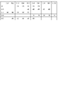
次に、無線チャネルの評価値の計算の具体的な例について説明する。図6は、端末で観測された干渉チャネルの情報を表形式で示す図である。
この図6に示された例では、APに接続された各STAで観測された、干渉チャネル情報の一覧が示される。この干渉チャネル情報の単位はdBmであるとする。 Next, a specific example of calculating the radio channel evaluation value will be described. FIG. 6 is a diagram showing information on interference channels observed by a terminal in tabular form.
The example shown in FIG. 6 shows a list of interference channel information observed by each STA connected to the AP. Assume that the unit of this interference channel information is dBm.
ここでは、干渉チャネル情報が観測される10個の単位チャネルが存在し、チャネルウィンドウの幅は、単位チャネルの帯域幅である200kHzが5つ束ねられて成る周波数帯域幅である1MHzであるとする。
Here, it is assumed that there are 10 unit channels in which interference channel information is observed, and the width of the channel window is 1 MHz, which is a frequency bandwidth obtained by bundling five unit channel bandwidths of 200 kHz. .
この例では、無線通信システムに干渉する5個の無線通信装置が確認されており、各々の無線チャネルの周波数帯域幅は単位チャネル5個分の周波数帯域幅である。また、この例では、単位チャネル毎に電波の受信強度が収集部10aにより取得されて無線通信制御装置10の内部メモリなどに記録される。
In this example, five wireless communication devices that interfere with the wireless communication system have been confirmed, and the frequency bandwidth of each wireless channel is the frequency bandwidth of five unit channels. Further, in this example, the radio wave reception intensity is acquired by the collecting unit 10a for each unit channel and recorded in the internal memory of the wireless communication control device 10 or the like.
図7は、各チャネルに係るチャネルウィンドウの一例を示す図である。
この図7に示された例では、上記のようにスキャン結果の収集および評価値の計算に用いられたチャネルウィンドウの一覧が示される。 FIG. 7 is a diagram showing an example of a channel window for each channel.
The example shown in FIG. 7 shows a list of channel windows used for collecting scan results and calculating evaluation values as described above.
この図7に示された例では、上記のようにスキャン結果の収集および評価値の計算に用いられたチャネルウィンドウの一覧が示される。 FIG. 7 is a diagram showing an example of a channel window for each channel.
The example shown in FIG. 7 shows a list of channel windows used for collecting scan results and calculating evaluation values as described above.
図7に示されるチャネルウィンドウは、単位チャネルであるチャネル「1」からチャネル「5」まで連続した5チャンネル分の周波数帯域幅である1MHz幅で成るチャネルウィンドウ、チャネル「2」からチャネル「6」まで連続した5チャンネル分の周波数帯域幅である1MHz幅で成るチャネルウィンドウ、チャネル「3」からチャネル「7」まで連続した5チャンネル分の周波数帯域幅である1MHz幅で成るチャネルウィンドウ、チャネル「4」からチャネル「8」まで連続した5チャンネル分の周波数帯域幅である1MHz幅で成るチャネルウィンドウ、チャネル「5」からチャネル「9」まで連続した5チャンネル分の周波数帯域幅である1MHz幅で成るチャネルウィンドウ、およびチャネル「6」からチャネル「10」までの5チャンネル分の周波数帯域幅である1MHz幅で成るチャネルウィンドウまでで成る、6種類のチャネルウィンドウである。
The channel window shown in FIG. 7 is a channel window having a width of 1 MHz, which is a frequency bandwidth for five consecutive channels from channel "1" to channel "5", which are unit channels, and channel "2" to channel "6". A channel window consisting of a 1 MHz width that is a frequency bandwidth for five consecutive channels up to, a channel window consisting of a 1 MHz width that is a frequency bandwidth for five consecutive channels from channel "3" to channel "7", channel "4 ” to channel “8” consisting of a 1 MHz width that is a frequency bandwidth for five consecutive channels, a channel window consisting of a 1 MHz width that is a frequency bandwidth for five consecutive channels from channel “5” to channel “9” There are six types of channel windows, including a channel window and a channel window with a width of 1 MHz, which is a frequency bandwidth for five channels from channel "6" to channel "10".
送信遅延時間によるチャネル評価が行なわれるために、チャネル評価値計算部10bは、まず、各チャネルウィンドウでの、上記観測された際にキャリアセンス(carrier sense)により検出される干渉BSSの数を以下の式(1)および(2)により計算する。複数の干渉BSSからの同時送信も考えられるが、ここでは、全ての干渉BSSが互いにキャリアセンス可能であり、別々のタイミングで送信された場合を想定する。
Since channel evaluation is performed based on the transmission delay time, the channel evaluation value calculation unit 10b first calculates the number of interfering BSSs detected by carrier sense when observed in each channel window as follows: is calculated by the formulas (1) and (2). Simultaneous transmissions from multiple interfering BSSs are also possible, but here we assume that all interfering BSSs can carrier sense each other and are transmitted at different timings.

上記式(1)および(2)の各パラメータの意味は以下の通りである。
a(n,k):端末nにおけるチャネルkで開始されるチャネルウィンドウの干渉BSSの数
k:チャネルインデックス(index)
Mn:端末nにより観測された干渉BSSのBSSID(Basic Service Set Identifier)の数
f(x):ステップ関数(step function)(電力強度の閾値Pthの判定)
P(I,k):干渉BSSIDのチャネルkに対する電力強度
In,m:端末nで観測されるm番目の干渉BSS The meaning of each parameter in the above formulas (1) and (2) is as follows.
a(n,k): number of interfering BSSs in the channel window starting with channel k in terminal n k: channel index (index)
Mn: number of BSSIDs (Basic Service Set Identifiers) of interfering BSSs observed by terminal n f(x): step function (determination of power intensity threshold P th )
P(I,k): Power intensity for channel k of interfering BSSID In,m: m-th interfering BSS observed at terminal n
図8は、干渉BSS数の計算結果の一例を表形式で示す図である。
Pthが「-80dBm」であるとき、図6に示された例では、各チャネルウィンドウの干渉BSS数の計算結果は図8に示された結果に対応する。 FIG. 8 is a diagram showing an example of calculation results of the number of interfering BSSs in tabular form.
When P th is “−80 dBm”, in the example shown in FIG. 6, the calculation result of the interfering BSS number for each channel window corresponds to the result shown in FIG.
また、各チャネルウィンドウの干渉BSS数から待ち行列理論(queuing theory)で計算される平均送信遅延時間は下記の式(3)~(6)により計算され得る。
下記の式(5)および(6)のρはチャネルの利用率を示す。ρが1.0より大きいときは、待ち行列モデル(queuing model)を用いてチャネルの待ち時間が計算されることができないため、干渉し合っているBSSの数に応じてチャネルの待ち時間が増加するとみなされて当該待ち時間が計算される。 Also, the average transmission delay time calculated by queuing theory from the number of interfering BSSs in each channel window can be calculated by the following equations (3) to (6).
ρ in equations (5) and (6) below indicates the utilization rate of the channel. When ρ is greater than 1.0, the channel latency cannot be calculated using a queuing model, so it is assumed that the channel latency increases with the number of interfering BSSs. and the waiting time is calculated.

式(3)~(6)の各パラメータ(parameters)の意味は、以下の通りである。
D:1つのBSSあたりのチャネル占有時間率
P:平均的な1つのシーケンス(sequence)時間
λ:待ち行列の平均パケット(packet)到着率
μ:待ち行列の平均サービス(service)時間
t:平均送信遅延時間
f(a(n,k)):実験結果またはデータなどに基づいて求められる、遅延時間の増大分の近似式 The meaning of each parameter in formulas (3) to (6) is as follows.
D: Channel occupancy rate per BSS P: Average one sequence time λ: Average packet arrival rate in queue μ: Average service time in queue t: Average transmission Delay time f(a(n,k)): Approximate formula for delay time increase obtained based on experimental results or data
送信時間の制限がある場合は、上記dが10%とされて平均送信遅延時間が計算されることで、チャネルの利用状況がモデル化され得る。
また、BSS内の端末台数、または各端末のトラヒック量が入力値として設定されても良いし、パケットがキャプチャ(capture)されるなどにより観測または監視された情報に基づく値が入力値として設定されても良い。 If there is a transmission time limit, the channel utilization can be modeled by calculating the average transmission delay time with d set to 10%.
Also, the number of terminals in the BSS or the traffic volume of each terminal may be set as an input value, or a value based on information observed or monitored by capturing packets or the like is set as an input value. can be
なお、上記待ち行列モデルで計算された平均送信遅延時間は、干渉BSS数に比例しない。このため、複数のSTAに係る送信遅延時間が合算されて評価値とされるとき、チャネルウィンドウにて観測された干渉BSS数が明らかに大きいSTAが1つでも存在すると、該当のチャネルでの送信遅延時間が大幅に長くなり、結果として評価値が大幅に悪い値となる。
Note that the average transmission delay time calculated by the above queuing model is not proportional to the number of interfering BSSs. Therefore, when the evaluation value is obtained by summing the transmission delay times of a plurality of STAs, if there is even one STA with a clearly large number of interfering BSSs observed in the channel window, transmission on the corresponding channel The delay time becomes significantly longer, resulting in a significantly worse evaluation value.
次に、実質干渉電力の計算の例について説明する。図9は、無線通信システム間の無線チャネルの部分的な干渉の一例を示す図である。
無線通信システム間で無線チャネルの所望信号(図9の符号a)と干渉信号(図9の符号b)との部分的な干渉が生じた場合、STAからの送信フレーム(flame)の宛て先であるアクセスポイント装置での受信品質が課題である。なお、所望信号および干渉信号には、図9の符号cで示される範囲で、受信強度の揺らぎが生じる。 Next, an example of calculation of real interference power will be described. FIG. 9 is a diagram illustrating an example of partial interference of radio channels between radio communication systems.
When partial interference occurs between the desired signal (symbol a in FIG. 9) and the interference signal (symbol b in FIG. 9) of the radio channel between the radio communication systems, the destination of the transmission frame (flame) from the STA is Reception quality at some access point devices is an issue. Note that the desired signal and the interference signal have received strength fluctuations within the range indicated by symbol c in FIG.
上記受信品質は、通常はSINR(Signal to Interference and Noise power Ratio(信号電力対雑音電力比))またはCIR(Carrier to Interference Ratio(信号電力対干渉電力比))で表現され、無線チャネル同士が完全に重複している場合は、この受信品質は、各無線チャネルでの受信信号の電力強度の差分で表現される。
ただし、本実施形態で対象としている、例えば図9で示される部分的な干渉が生じた場合、その影響は受信電力強度の差分では表現され得ない。 The reception quality is usually expressed by SINR (Signal to Interference and Noise power ratio) or CIR (Carrier to Interference Ratio). , the reception quality is expressed by the difference in the power intensity of the received signal on each radio channel.
However, if partial interference, for example, shown in FIG. 9 occurs, which is the object of this embodiment, the effect cannot be represented by the difference in received power intensity.
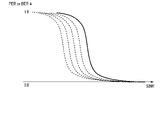
そこで、本実施形態では、干渉の影響をPERまたはBER(Bit Error Rate(ビット誤り率))とし、同じPERまたはBERとなるSINR値は実質SINRであるとする。図10は、PERまたはBERからSINRへのマッピングの一例を示す図である。
PERまたはBERからのSINRへのマッピングには、既存のデータが使用される。なお、この既存のデータには、無線チャネルの所望信号と干渉信号とが完全に重複した状態のデータが使用される。 Therefore, in the present embodiment, the influence of interference is defined as PER or BER (Bit Error Rate), and the SINR value with the same PER or BER is the actual SINR. FIG. 10 is a diagram illustrating an example of mapping from PER or BER to SINR.
Existing data is used for the mapping from PER or BER to SINR. It should be noted that data in which the desired signal and the interference signal of the radio channel are completely overlapped is used as the existing data.
本実施形態では、実質SINRから算出される干渉電力は、実質干渉電力であるとする。この実質干渉電力は、システムに干渉するAPからの受信信号の電力強度から、部分干渉時のSINRの差分を減じた値として計算され得る。
In this embodiment, the interference power calculated from the real SINR is the real interference power. This net interference power can be calculated as the power strength of received signals from APs interfering with the system minus the SINR difference at the time of partial interference.
なお、この実質干渉電力は、事前に得られる実験結果などから既存データに対して一定値だけずれた値、例えば部分干渉時のSINRの差分として計算されても良いし、既存データの1点1点についてマッピングされても良い。
Note that this real interference power may be calculated as a value shifted by a certain value from the existing data based on experimental results obtained in advance, for example, as a difference in SINR at the time of partial interference. It may be mapped in terms of points.
また、このときに使用される、所望信号と干渉信号との受信強度には、伝搬路の影響、および端末の送信機能の精度に起因する揺らぎが存在するため、この揺らぎの範囲がマージン値(margin value)として測定された受信強度が補正された後で、干渉の影響が見積もられる方法も存在する。
In addition, since the received strength of the desired signal and the interference signal used at this time fluctuates due to the influence of the propagation path and the accuracy of the transmission function of the terminal, the range of this fluctuation is the margin value ( There are also methods in which the influence of interference is estimated after the received power measured as margin value) is corrected.
最終的に、全ての干渉する端末に対して、1つの無線チャネルに係る実質干渉電力が計算され、各端末に対して計算された値が合算された値が、他の無線チャネルに係る実質干渉電力と比較して小さければ、該当の無線チャネルは、干渉の影響が小さい無線チャネルと判定できる。
Finally, the net interference power for one radio channel is calculated for all interfering terminals, and the sum of the calculated values for each terminal is the net interference power for other radio channels. If it is small compared to the power, it can be determined that the radio channel is less affected by interference.
また、各実施形態に記載された手法は、計算機(コンピュータ)に実行させることができるプログラム(ソフトウエア手段)として、例えば磁気ディスク(フロッピー(登録商標)ディスク(Floppy disk)、ハードディスク(hard disk)等)、光ディスク(optical disc)(CD-ROM、DVD、MO等)、半導体メモリ(ROM、RAM、フラッシュメモリ(Flash memory)等)等の記録媒体に格納し、また通信媒体により伝送して頒布され得る。なお、媒体側に格納されるプログラムには、計算機に実行させるソフトウエア手段(実行プログラムのみならずテーブル(table)、データ構造も含む)を計算機内に構成させる設定プログラムをも含む。本装置を実現する計算機は、記録媒体に記録されたプログラムを読み込み、また場合により設定プログラムによりソフトウエア手段を構築し、このソフトウエア手段によって動作が制御されることにより上述した処理を実行する。なお、本明細書でいう記録媒体は、頒布用に限らず、計算機内部あるいはネットワークを介して接続される機器に設けられた磁気ディスク、半導体メモリ等の記憶媒体を含むものである。
In addition, the method described in each embodiment can be applied to a program (software means) that can be executed by a computer (computer), for example, a magnetic disk (floppy disk, hard disk) etc.), optical discs (CD-ROM, DVD, MO, etc.), semiconductor memory (ROM, RAM, flash memory, etc.) and other recording media, or transmitted and distributed via communication media can be The programs stored on the medium also include a setting program for configuring software means (including not only execution programs but also tables and data structures) to be executed by the computer. A computer that realizes this device reads a program recorded on a recording medium, and optionally constructs software means by a setting program, and executes the above-described processing by controlling the operation by this software means. The term "recording medium" as used herein is not limited to those for distribution, and includes storage media such as magnetic disks, semiconductor memories, etc. provided in computers or devices connected via a network.
なお、本発明は、上記実施形態に限定されるものではなく、実施段階ではその要旨を逸脱しない範囲で種々に変形することが可能である。また、各実施形態は適宜組み合わせて実施してもよく、その場合組み合わせた効果が得られる。更に、上記実施形態には種々の発明が含まれており、開示される複数の構成要件から選択された組み合わせにより種々の発明が抽出され得る。例えば、実施形態に示される全構成要件からいくつかの構成要件が削除されても、課題が解決でき、効果が得られる場合には、この構成要件が削除された構成が発明として抽出され得る。
It should be noted that the present invention is not limited to the above-described embodiments, and can be variously modified in the implementation stage without departing from the gist of the present invention. Further, each embodiment may be implemented in combination as appropriate, in which case the combined effect can be obtained. Furthermore, various inventions are included in the above embodiments, and various inventions can be extracted by combinations selected from a plurality of disclosed constituent elements. For example, even if some constituent elements are deleted from all the constituent elements shown in the embodiments, if the problem can be solved and effects can be obtained, the configuration with the constituent elements deleted can be extracted as an invention.
1 …AP(アクセスポイント装置)
2-1a~2-4a,2-1b~2-4b…STA(ステーション装置)
10 …無線通信制御装置
11 …制御回路
12 …メモリ
12a…制御プログラムエリア
12b…管理情報エリア
13 …ディスクドライブ
13a…記憶媒体
14 …ユーザインターフェイス
15 …有線通信モジュール
16 …無線通信モジュール
17 …GPSセンサ
18 …タイマ 1 … AP (access point device)
2-1a to 2-4a, 2-1b to 2-4b ... STA (station equipment)
DESCRIPTION OFSYMBOLS 10... Wireless communication control apparatus 11... Control circuit 12... Memory 12a... Control program area 12b... Management information area 13... Disk drive 13a... Storage medium 14... User interface 15... Wired communication module 16... Wireless communication module 17... GPS sensor 18 …timer
2-1a~2-4a,2-1b~2-4b…STA(ステーション装置)
10 …無線通信制御装置
11 …制御回路
12 …メモリ
12a…制御プログラムエリア
12b…管理情報エリア
13 …ディスクドライブ
13a…記憶媒体
14 …ユーザインターフェイス
15 …有線通信モジュール
16 …無線通信モジュール
17 …GPSセンサ
18 …タイマ 1 … AP (access point device)
2-1a to 2-4a, 2-1b to 2-4b ... STA (station equipment)
DESCRIPTION OF
Claims (8)
- アクセスポイント装置と複数のステーション装置と無線通信制御装置とが無線通信を行なう無線通信システムであって、
前記無線通信制御装置は、
前記アクセスポイント装置と前記ステーション装置との間の無線通信に用いられる複数の無線周波数チャネルの各々の使用状況を示す情報を収集する収集部と、
前記収集部により収集された情報に基づいて、前記複数の無線周波数チャネルの各々について、前記無線通信に最適な無線周波数チャネルの選択に係る評価値を計算する計算部と、
前記計算部により計算された評価値に基づいて、前記複数の無線周波数チャネルのうち、前記無線通信に最適な無線周波数チャネルを選択する選択部と、を備える、
無線通信システム。 A wireless communication system in which an access point device, a plurality of station devices, and a wireless communication control device perform wireless communication,
The radio communication control device,
a collection unit that collects information indicating usage status of each of a plurality of radio frequency channels used for wireless communication between the access point device and the station device;
a calculation unit that calculates, for each of the plurality of radio frequency channels, an evaluation value related to selection of the optimum radio frequency channel for radio communication based on the information collected by the collection unit;
a selection unit that selects an optimum radio frequency channel for the wireless communication from among the plurality of radio frequency channels based on the evaluation value calculated by the calculation unit;
wireless communication system. - 前記収集部は、
前記複数の無線周波数チャネルの1つを選択し、前記選択された無線周波数チャネルの使用状況を示す情報を収集し、
前記計算部は、
前記収集部により収集された、前記選択された無線周波数チャネルについて、前記評価値を計算し、
前記選択部は、
前記計算部により計算された、前記選択された無線周波数チャネルについて計算された評価値が、前記無線通信に最適な無線周波数チャネルとしての選択に係る条件を満たすときに、前記選択された無線周波数チャネルを、前記無線通信に最適な無線周波数チャネルとして選択する、
請求項1に記載の無線通信システム。 The collection unit is
selecting one of the plurality of radio frequency channels and collecting information indicative of usage of the selected radio frequency channel;
The calculation unit
calculating the evaluation value for the selected radio frequency channel collected by the collection unit;
The selection unit
The selected radio frequency channel when the evaluation value calculated for the selected radio frequency channel by the calculation unit satisfies the conditions for selection as the optimum radio frequency channel for the radio communication. as the best radio frequency channel for said wireless communication;
A wireless communication system according to claim 1 . - 前記計算部は、
前記アクセスポイント装置と前記ステーション装置との間での無線通信の干渉が生ずる無線通信装置の台数と、前記無線周波数チャネルの使用時における送信時間の制限に係る条件に基づいて、前記アクセスポイント装置との前記ステーション装置との間の無線通信による信号の送信の遅延時間を前記評価値として計算する、
請求項1に記載の無線通信システム。 The calculation unit
Based on the number of wireless communication devices that cause interference in wireless communication between the access point device and the station device, and the conditions related to the transmission time limit when using the radio frequency channel, the access point device and the station device calculating, as the evaluation value, the delay time of signal transmission by wireless communication with the station device of
A wireless communication system according to claim 1 . - 前記選択部は、
前記計算部により計算された評価値が最良である無線周波数チャネルを、前記無線通信に最適な無線周波数チャネルの候補として選択し、
前記計算部により計算された評価値が最良である複数の無線周波数チャネルの候補があるときに、当該複数の無線周波数チャネルの各々について、前記アクセスポイント装置で受信される所望の信号に干渉する信号の電力を計算し、前記計算された電力が最も小さい無線チャネルを前記無線通信に最適な無線周波数チャネルとして選択する、
請求項1に記載の無線通信システム。 The selection unit
selecting the radio frequency channel with the best evaluation value calculated by the calculation unit as a candidate for the radio frequency channel most suitable for the radio communication;
A signal that interferes with a desired signal received by the access point device for each of the plurality of radio frequency channel candidates when there are a plurality of radio frequency channel candidates with the best evaluation value calculated by the calculation unit. and selecting the radio channel with the lowest calculated power as the best radio frequency channel for the radio communication.
A wireless communication system according to claim 1 . - アクセスポイント装置と複数のステーション装置とが無線通信を行ない、前記無線通信が無線通信制御装置により制御される無線通信方法であって、
前記無線通信制御装置により、前記アクセスポイント装置と前記ステーション装置との間の無線通信に用いられる複数の無線周波数チャネルの各々の使用状況を示す情報を収集することと、
前記収集された情報に基づいて、前記複数の無線周波数チャネルの各々について、前記無線通信に最適な無線周波数チャネルの選択に係る評価値を計算することと、
前記計算された評価値に基づいて、前記複数の無線周波数チャネルのうち、前記無線通信に最適な無線周波数チャネルを選択することと、
を備える無線通信方法。 A wireless communication method in which an access point device and a plurality of station devices perform wireless communication, and the wireless communication is controlled by a wireless communication control device,
collecting, by the radio communication control device, information indicating the usage status of each of a plurality of radio frequency channels used for radio communication between the access point device and the station device;
calculating, for each of the plurality of radio frequency channels, an evaluation value for selection of an optimal radio frequency channel for the radio communication based on the collected information;
selecting an optimal radio frequency channel for the radio communication from among the plurality of radio frequency channels based on the calculated evaluation value;
A wireless communication method comprising: - アクセスポイント装置と複数のステーション装置と無線通信を行なう無線通信システムの無線通信制御装置であって、
前記アクセスポイント装置と前記ステーション装置との間の無線通信に用いられる複数の無線周波数チャネルの各々の使用状況を示す情報を収集する収集部と、
前記収集部により収集された情報に基づいて、前記複数の無線周波数チャネルの各々について、前記無線通信に最適な無線周波数チャネルの選択に係る評価値を計算する計算部と、
前記計算部により計算された評価値に基づいて、前記複数の無線周波数チャネルのうち、前記無線通信に最適な無線周波数チャネルを選択する選択部と、
を備える無線通信制御装置。 A wireless communication control device for a wireless communication system that performs wireless communication with an access point device and a plurality of station devices,
a collection unit that collects information indicating usage status of each of a plurality of radio frequency channels used for wireless communication between the access point device and the station device;
a calculation unit that calculates, for each of the plurality of radio frequency channels, an evaluation value related to selection of the optimum radio frequency channel for radio communication based on the information collected by the collection unit;
a selection unit that selects an optimum radio frequency channel for the wireless communication from among the plurality of radio frequency channels based on the evaluation value calculated by the calculation unit;
A radio communication control device comprising: - 前記収集部は、
前記複数の無線周波数チャネルの1つを選択し、前記選択された無線周波数チャネルの使用状況を示す情報を収集し、
前記計算部は、
前記収集部により収集された、前記選択された無線周波数チャネルについて、前記評価値を計算し、
前記選択部は、
前記計算部により計算された、前記選択された無線周波数チャネルについて計算された評価値が、前記無線通信に最適な無線周波数チャネルとしての選択に係る条件を満たすときに、前記選択された無線周波数チャネルを、前記無線通信に最適な無線周波数チャネルとして選択する、
請求項6に記載の無線通信制御装置。 The collection unit is
selecting one of the plurality of radio frequency channels and collecting information indicative of usage of the selected radio frequency channel;
The calculation unit
calculating the evaluation value for the selected radio frequency channel collected by the collection unit;
The selection unit
The selected radio frequency channel when the evaluation value calculated for the selected radio frequency channel by the calculation unit satisfies the conditions for selection as the optimum radio frequency channel for the radio communication. as the best radio frequency channel for said wireless communication;
The radio communication control device according to claim 6. - 請求項6または7に記載の無線通信制御装置の前記各部としてプロセッサを機能させるプログラム。 A program that causes a processor to function as each part of the radio communication control device according to claim 6 or 7.
Priority Applications (2)
| Application Number | Priority Date | Filing Date | Title |
|---|---|---|---|
| PCT/JP2021/022895 WO2022264320A1 (en) | 2021-06-16 | 2021-06-16 | Wireless communication system, wireless communication method, wireless communication control device, and program |
| JP2023528846A JPWO2022264320A1 (en) | 2021-06-16 | 2021-06-16 |
Applications Claiming Priority (1)
| Application Number | Priority Date | Filing Date | Title |
|---|---|---|---|
| PCT/JP2021/022895 WO2022264320A1 (en) | 2021-06-16 | 2021-06-16 | Wireless communication system, wireless communication method, wireless communication control device, and program |
Publications (1)
| Publication Number | Publication Date |
|---|---|
| WO2022264320A1 true WO2022264320A1 (en) | 2022-12-22 |
Family
ID=84526467
Family Applications (1)
| Application Number | Title | Priority Date | Filing Date |
|---|---|---|---|
| PCT/JP2021/022895 WO2022264320A1 (en) | 2021-06-16 | 2021-06-16 | Wireless communication system, wireless communication method, wireless communication control device, and program |
Country Status (2)
| Country | Link |
|---|---|
| JP (1) | JPWO2022264320A1 (en) |
| WO (1) | WO2022264320A1 (en) |
Citations (3)
| Publication number | Priority date | Publication date | Assignee | Title |
|---|---|---|---|---|
| JP2003078532A (en) * | 2001-09-03 | 2003-03-14 | Ntt Docomo Inc | Transmission control method, communication system, communication equipment and communication terminal |
| JP2006504356A (en) * | 2002-11-04 | 2006-02-02 | テルコーディア テクノロジーズ インコーポレイテッド | Method and system for configuring cellular network in real time |
| JP2016076887A (en) * | 2014-10-08 | 2016-05-12 | 日本電信電話株式会社 | Radio communication system, mobile communication base station, radio terminal device, and radio communication method |
-
2021
- 2021-06-16 WO PCT/JP2021/022895 patent/WO2022264320A1/en active Application Filing
- 2021-06-16 JP JP2023528846A patent/JPWO2022264320A1/ja active Pending
Patent Citations (3)
| Publication number | Priority date | Publication date | Assignee | Title |
|---|---|---|---|---|
| JP2003078532A (en) * | 2001-09-03 | 2003-03-14 | Ntt Docomo Inc | Transmission control method, communication system, communication equipment and communication terminal |
| JP2006504356A (en) * | 2002-11-04 | 2006-02-02 | テルコーディア テクノロジーズ インコーポレイテッド | Method and system for configuring cellular network in real time |
| JP2016076887A (en) * | 2014-10-08 | 2016-05-12 | 日本電信電話株式会社 | Radio communication system, mobile communication base station, radio terminal device, and radio communication method |
Also Published As
| Publication number | Publication date |
|---|---|
| JPWO2022264320A1 (en) | 2022-12-22 |
Similar Documents
| Publication | Publication Date | Title |
|---|---|---|
| KR101571904B1 (en) | Apparatus and method for allocating frequency resource to micro UE in a mobile communication system | |
| US9185714B2 (en) | Method and system for dynamically assigning channels across multiple radios in a wireless LAN | |
| JP4921562B2 (en) | Method and apparatus for measuring interference in a radio base station | |
| JP5150153B2 (en) | Resource allocation apparatus, centralized control apparatus, radio base station, radio communication system, resource allocation method, and resource allocation program | |
| KR102166093B1 (en) | Apparatus and method for connecting access point in a wireless communication system | |
| CN110800335B (en) | Radio sensor coverage estimation for wireless network guarantees | |
| CN101309130B (en) | Wireless communication apparatus and method | |
| EP3053389B1 (en) | Controlling uplink transmissions from interfering stations | |
| KR101388557B1 (en) | System and method for selecting channel, access point, and recording medium thereof | |
| Siris et al. | A simple end-to-end throughput model for 802.11 multi-radio multi-rate wireless mesh networks | |
| WO2021233331A1 (en) | Communication channel optimization method and apparatus, electronic device, and storage medium | |
| US10887774B2 (en) | Mobile communications system expansion method and device, storage medium, and program product | |
| KR101838247B1 (en) | Method and apparatus for detemining dual thresholds for channel sensing in heterogeneous network | |
| WO2022264320A1 (en) | Wireless communication system, wireless communication method, wireless communication control device, and program | |
| JP5360207B2 (en) | Base station apparatus, edge user estimation method and program | |
| JP6891631B2 (en) | Communication device, control device, communication system, communication method, and communication control program | |
| JP5463194B2 (en) | Congestion degree estimation device, congestion degree estimation method, and control program | |
| WO2018108851A1 (en) | Adapting the transmission power of a wireless access point | |
| Su et al. | Design and analysis of a multi-channel cognitive MAC protocol for dynamic access spectrum networks | |
| EP3391590B1 (en) | Noise floor degradation detection for co-located radios | |
| US20170005898A1 (en) | Distributed saturation detection method for wireless network nodes | |
| Chen et al. | Select: Self-learning collision avoidance for wireless networks | |
| JP7298773B2 (en) | Wireless communication system, wireless communication control device and method | |
| KR101551563B1 (en) | Method and apparatus for wifi offloading using wifi network in a cellular and wifi overlay network | |
| KR20180045705A (en) | Apparatus and Method for Packet Data Scheduling in Network Device of WLAN Systems |
Legal Events
| Date | Code | Title | Description |
|---|---|---|---|
| 121 | Ep: the epo has been informed by wipo that ep was designated in this application |
Ref document number: 21945997 Country of ref document: EP Kind code of ref document: A1 |
|
| WWE | Wipo information: entry into national phase |
Ref document number: 2023528846 Country of ref document: JP |
|
| NENP | Non-entry into the national phase |
Ref country code: DE |