WO2022263052A1 - Installation de pompage de fluide cryogénique et station de remplissage comprenant une telle installation. - Google Patents
Installation de pompage de fluide cryogénique et station de remplissage comprenant une telle installation. Download PDFInfo
- Publication number
- WO2022263052A1 WO2022263052A1 PCT/EP2022/062105 EP2022062105W WO2022263052A1 WO 2022263052 A1 WO2022263052 A1 WO 2022263052A1 EP 2022062105 W EP2022062105 W EP 2022062105W WO 2022263052 A1 WO2022263052 A1 WO 2022263052A1
- Authority
- WO
- WIPO (PCT)
- Prior art keywords
- motor
- installation
- installation according
- upper frame
- transformation system
- Prior art date
- Legal status (The legal status is an assumption and is not a legal conclusion. Google has not performed a legal analysis and makes no representation as to the accuracy of the status listed.)
- Ceased
Links
Images




Classifications
-
- F—MECHANICAL ENGINEERING; LIGHTING; HEATING; WEAPONS; BLASTING
- F04—POSITIVE - DISPLACEMENT MACHINES FOR LIQUIDS; PUMPS FOR LIQUIDS OR ELASTIC FLUIDS
- F04B—POSITIVE-DISPLACEMENT MACHINES FOR LIQUIDS; PUMPS
- F04B15/00—Pumps adapted to handle specific fluids, e.g. by selection of specific materials for pumps or pump parts
- F04B15/06—Pumps adapted to handle specific fluids, e.g. by selection of specific materials for pumps or pump parts for liquids near their boiling point, e.g. under subnormal pressure
- F04B15/08—Pumps adapted to handle specific fluids, e.g. by selection of specific materials for pumps or pump parts for liquids near their boiling point, e.g. under subnormal pressure the liquids having low boiling points
-
- F—MECHANICAL ENGINEERING; LIGHTING; HEATING; WEAPONS; BLASTING
- F04—POSITIVE - DISPLACEMENT MACHINES FOR LIQUIDS; PUMPS FOR LIQUIDS OR ELASTIC FLUIDS
- F04B—POSITIVE-DISPLACEMENT MACHINES FOR LIQUIDS; PUMPS
- F04B23/00—Pumping installations or systems
- F04B23/02—Pumping installations or systems having reservoirs
- F04B23/021—Pumping installations or systems having reservoirs the pump being immersed in the reservoir
-
- F—MECHANICAL ENGINEERING; LIGHTING; HEATING; WEAPONS; BLASTING
- F04—POSITIVE - DISPLACEMENT MACHINES FOR LIQUIDS; PUMPS FOR LIQUIDS OR ELASTIC FLUIDS
- F04B—POSITIVE-DISPLACEMENT MACHINES FOR LIQUIDS; PUMPS
- F04B37/00—Pumps having pertinent characteristics not provided for in, or of interest apart from, groups F04B25/00 - F04B35/00
- F04B37/06—Pumps having pertinent characteristics not provided for in, or of interest apart from, groups F04B25/00 - F04B35/00 for evacuating by thermal means
- F04B37/08—Pumps having pertinent characteristics not provided for in, or of interest apart from, groups F04B25/00 - F04B35/00 for evacuating by thermal means by condensing or freezing, e.g. cryogenic pumps
-
- F—MECHANICAL ENGINEERING; LIGHTING; HEATING; WEAPONS; BLASTING
- F04—POSITIVE - DISPLACEMENT MACHINES FOR LIQUIDS; PUMPS FOR LIQUIDS OR ELASTIC FLUIDS
- F04B—POSITIVE-DISPLACEMENT MACHINES FOR LIQUIDS; PUMPS
- F04B39/00—Component parts, details, or accessories, of pumps or pumping systems specially adapted for elastic fluids, not otherwise provided for in, or of interest apart from, groups F04B25/00 - F04B37/00
- F04B39/06—Cooling; Heating; Prevention of freezing
- F04B39/064—Cooling by a cooling jacket in the pump casing
-
- F—MECHANICAL ENGINEERING; LIGHTING; HEATING; WEAPONS; BLASTING
- F04—POSITIVE - DISPLACEMENT MACHINES FOR LIQUIDS; PUMPS FOR LIQUIDS OR ELASTIC FLUIDS
- F04B—POSITIVE-DISPLACEMENT MACHINES FOR LIQUIDS; PUMPS
- F04B53/00—Component parts, details or accessories not provided for in, or of interest apart from, groups F04B1/00 - F04B23/00 or F04B39/00 - F04B47/00
-
- F—MECHANICAL ENGINEERING; LIGHTING; HEATING; WEAPONS; BLASTING
- F04—POSITIVE - DISPLACEMENT MACHINES FOR LIQUIDS; PUMPS FOR LIQUIDS OR ELASTIC FLUIDS
- F04B—POSITIVE-DISPLACEMENT MACHINES FOR LIQUIDS; PUMPS
- F04B53/00—Component parts, details or accessories not provided for in, or of interest apart from, groups F04B1/00 - F04B23/00 or F04B39/00 - F04B47/00
- F04B53/08—Cooling; Heating; Preventing freezing
-
- F—MECHANICAL ENGINEERING; LIGHTING; HEATING; WEAPONS; BLASTING
- F04—POSITIVE - DISPLACEMENT MACHINES FOR LIQUIDS; PUMPS FOR LIQUIDS OR ELASTIC FLUIDS
- F04B—POSITIVE-DISPLACEMENT MACHINES FOR LIQUIDS; PUMPS
- F04B53/00—Component parts, details or accessories not provided for in, or of interest apart from, groups F04B1/00 - F04B23/00 or F04B39/00 - F04B47/00
- F04B53/22—Arrangements for enabling ready assembly or disassembly
-
- F—MECHANICAL ENGINEERING; LIGHTING; HEATING; WEAPONS; BLASTING
- F04—POSITIVE - DISPLACEMENT MACHINES FOR LIQUIDS; PUMPS FOR LIQUIDS OR ELASTIC FLUIDS
- F04B—POSITIVE-DISPLACEMENT MACHINES FOR LIQUIDS; PUMPS
- F04B9/00—Piston machines or pumps characterised by the driving or driven means to or from their working members
- F04B9/02—Piston machines or pumps characterised by the driving or driven means to or from their working members the means being mechanical
-
- F—MECHANICAL ENGINEERING; LIGHTING; HEATING; WEAPONS; BLASTING
- F04—POSITIVE - DISPLACEMENT MACHINES FOR LIQUIDS; PUMPS FOR LIQUIDS OR ELASTIC FLUIDS
- F04B—POSITIVE-DISPLACEMENT MACHINES FOR LIQUIDS; PUMPS
- F04B9/00—Piston machines or pumps characterised by the driving or driven means to or from their working members
- F04B9/02—Piston machines or pumps characterised by the driving or driven means to or from their working members the means being mechanical
- F04B9/04—Piston machines or pumps characterised by the driving or driven means to or from their working members the means being mechanical the means being cams, eccentrics or pin-and-slot mechanisms
-
- F—MECHANICAL ENGINEERING; LIGHTING; HEATING; WEAPONS; BLASTING
- F04—POSITIVE - DISPLACEMENT MACHINES FOR LIQUIDS; PUMPS FOR LIQUIDS OR ELASTIC FLUIDS
- F04B—POSITIVE-DISPLACEMENT MACHINES FOR LIQUIDS; PUMPS
- F04B15/00—Pumps adapted to handle specific fluids, e.g. by selection of specific materials for pumps or pump parts
- F04B15/06—Pumps adapted to handle specific fluids, e.g. by selection of specific materials for pumps or pump parts for liquids near their boiling point, e.g. under subnormal pressure
- F04B15/08—Pumps adapted to handle specific fluids, e.g. by selection of specific materials for pumps or pump parts for liquids near their boiling point, e.g. under subnormal pressure the liquids having low boiling points
- F04B2015/081—Liquefied gases
- F04B2015/0822—Hydrogen
-
- F—MECHANICAL ENGINEERING; LIGHTING; HEATING; WEAPONS; BLASTING
- F04—POSITIVE - DISPLACEMENT MACHINES FOR LIQUIDS; PUMPS FOR LIQUIDS OR ELASTIC FLUIDS
- F04B—POSITIVE-DISPLACEMENT MACHINES FOR LIQUIDS; PUMPS
- F04B35/00—Piston pumps specially adapted for elastic fluids and characterised by the driving means to their working members, or by combination with, or adaptation to, specific driving engines or motors, not otherwise provided for
- F04B35/04—Piston pumps specially adapted for elastic fluids and characterised by the driving means to their working members, or by combination with, or adaptation to, specific driving engines or motors, not otherwise provided for the means being electric
-
- F—MECHANICAL ENGINEERING; LIGHTING; HEATING; WEAPONS; BLASTING
- F17—STORING OR DISTRIBUTING GASES OR LIQUIDS
- F17C—VESSELS FOR CONTAINING OR STORING COMPRESSED, LIQUEFIED OR SOLIDIFIED GASES; FIXED-CAPACITY GAS-HOLDERS; FILLING VESSELS WITH, OR DISCHARGING FROM VESSELS, COMPRESSED, LIQUEFIED, OR SOLIDIFIED GASES
- F17C2223/00—Handled fluid before transfer, i.e. state of fluid when stored in the vessel or before transfer from the vessel
- F17C2223/01—Handled fluid before transfer, i.e. state of fluid when stored in the vessel or before transfer from the vessel characterised by the phase
- F17C2223/0146—Two-phase
- F17C2223/0153—Liquefied gas, e.g. LPG, GPL
- F17C2223/0161—Liquefied gas, e.g. LPG, GPL cryogenic, e.g. LNG, GNL, PLNG
Definitions
- the invention relates to a cryogenic fluid pumping installation as well as a filling station comprising such an installation.
- the invention relates more particularly to a cryogenic fluid pumping installation comprising a sealed enclosure intended to contain a bath of cryogenic fluid, the enclosure housing a compression chamber communicating with the bath and a movable piston to ensure the compression of the fluid in the compression chamber, the piston being mounted at a first end of a rod, the apparatus comprising a mechanism for driving a second end of the rod back and forth in a longitudinal direction of movement, the drive mechanism comprising a motor provided with a rotating shaft and a mechanical transformation system converting the rotational movement of the rotating shaft into a translational movement, in the operating configuration of the installation, the longitudinal direction of movement of the piston rod being vertical, the motor being rigidly fixed to an upper frame.
- a classic solution for actuating a reciprocating piston pump uses a motor and a mechanical system for transforming the movement of the rotating shaft of the motor into translational movement (connecting rod/crank system and/or reduction gear and/or speed).
- cryogenic pumps operate with a horizontal piston pin. This is possible with a vacuum insulated cold end.
- the pump In hydrogen refueling stations, the pump must be available for pumping 24 hours a day. Therefore, it is best to place the cold end in a vacuum-insulated cryogenic liquid bath ("sump”) ("dewar”) to ensure that it stays cold. A vertical orientation of the piston is in this case more appropriate.
- a gimbal system can be used to transmit torque from the rotational output of the motor gearbox to the crank of the mechanical unit which converts the rotational motion provided by the motor into reciprocating translational motion of the rod of the plunger. This allows an optimal assembly without requiring very constraining tolerances.
- a roller screw linear actuator solution is also easy to implement due to its compactness. This solution is however not suitable for high pressure cryogenic applications due to low efficiency and reliability.
- An object of the present invention is to overcome all or part of the drawbacks of the prior art noted above.
- the installation according to the invention is essentially characterized in that the mechanical transformation system is also rigidly fixed to an upper frame which comprises the motor frame or a separate frame rigidly connected to the motor frame.
- embodiments of the invention may include one or more of the following features:
- the invention also relates to a filling station for tanks or pressurized gas pipes comprising a source of liquefied gas, in particular a tank of liquefied hydrogen, a withdrawal circuit having a first end connected to the source and at least a second end intended to be connected to a reservoir to be filled, the withdrawal circuit comprising a pumping installation conforming to any one of the characteristics above or below.
- the invention may also relate to any alternative device or method comprising any combination of the characteristics above or below within the scope of the claims.
- FIG. 1 represents a perspective view, schematic and partial, illustrating a first possible embodiment of a pumping installation according to the invention
- FIG. 1 represents a front view, schematic and partial, illustrating the first embodiment of the installation and comprising a cryogenic fluid tank,
- FIG. 1 represents a schematic partial sectional view illustrating a detail of the installation and in particular an example of a compression chamber structure
- FIG. 1 represents a front view, schematic and partial, illustrating a second embodiment of the installation
- FIG. 1 represents a front view, schematic and partial, illustrating a third embodiment of the installation
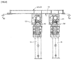
- FIG. 1 represents a top view, schematic and partial, illustrating a fourth embodiment of the installation
- FIG. 1 represents a side view, schematic and partial, illustrating a fifth embodiment of the installation
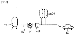
- FIG. 1 represents a schematic and partial view, illustrating an example of a filling station using such a compression device
- FIG. 1 represents a perspective view, schematic and partial, illustrating an example of a support structure for the frames of the installation.
- the cryogenic fluid pumping installation 1 represented comprises a sealed enclosure 13 intended to contain a bath of cryogenic fluid.
- the enclosure 13 can be thermally insulated under vacuum and houses a compression chamber 3 communicating with the bath and a movable piston 5 to ensure the compression of the fluid in the compression chamber 3 cf. .
- the piston 5 is mounted at a first end of a piston rod 50.
- the device 1 comprises a mechanism 21 for driving a second end of the rod 50 in a back and forth movement in a longitudinal direction A of movement.
- the drive mechanism 21 comprises a motor 121 (with, where appropriate, a gearbox or the like) provided with a rotating shaft 211 and a system 212 of mechanical transformation converting the rotational movement of the rotating shaft 211 into a movement of translation of the rod 50.
- the mechanical system 212 converting the rotational movement of the rotating shaft 211 into a translational movement of the rod 50 of the piston can be of the connecting rod and crank type and housed in a casing.
- the rotating shaft 211 of the motor 121 is coupled to the mechanical transformation system 212 via an axis comprising a connection system such as a rigid connection or a universal joint for example.
- a universal joint coupling can allow greater assembly tolerances.
- the cardanic coupling between the two units also allows the “useful” torque to be transferred optimally with relatively easy maintenance.
- motor 121 and mechanical transformation system 212 can be housed in respective casings.
- the casing of the 212 motion transformation system can be easily removed to access the cold end placed vertically under the mechanism (under a crank, in particular in the case of a connecting rod and crank mechanism).
- the mechanical transformation system 212 is also rigidly fixed to an upper frame which may be the same frame 6, 26 of the motor 121 or a separate frame rigidly connected to the frame 6, 26 of the motor 121.
- the motor 121 (and its casing if applicable) can be suspended from its frame 6, 26.
- the motor 121 and its casing can be fixed by its upper part to an underside of the upper frame 26 (by example by screwing or other).
- the mechanical transformation system 212 (and its casing if applicable) can be suspended from its upper frame 16, in particular fixed by its upper part to the frame (idem for example by screwing or the like).
- each element 121, 212 can be dismantled from the frame 16, 26 to which it is fixed and independently of the other element 121, 212. This is advantageous for maintenance.
- This structure can support the suspended container 13 for more flexibility. That is to say that an upper end of the container 13 can be suspended from a lower end of the mechanical transformation system 212 (in particular from its casing) by a connecting member 9 such as one or more pins and/or a sleeve. The lower end of the container 13 can thus be located above the ground without resting on a lower support.
- cryogenic pipes connecting this container 13 and a tank 17 of cryogenic liquid can be flexible to absorb the thermal contractions and make it possible to tolerate minor misalignments.
- the motor 121 and its casing can be rigidly connected to their upper frame 26, 6.
- the mechanical transformation system 212 and its casing can be rigidly connected to their upper frame 16, 6.
- the upper frame of the engine 121 may comprise a first set of horizontal support beam(s) 6, 26 connected to a supporting structure 60 which may comprise vertical feet resting on the ground.
- the upper frame of the mechanical transformation system 212 may comprise a second set of support beam(s) 6, 16.
- the second set of beam(s) is rigidly connected to the first set of beam(s) 6, 26 support.
- the two sets of beam(s) can be at least partly common.
- the motor 121 and the system 212 of mechanical transformation can be connected to two distinct portions 16, 26 of the same beam (for example transverse) connected to a beam 6 (extending for example along a longitudinal direction of structure ).
- the two beam portions 26, 16 can be connected transversely to the common beam 6.
- the two beam portions 26, 16 can be located transversely on either side of the common beam 6 (in particular at the same longitudinal position along the longitudinal beam 6 of the structure).
- At least one of the two beam portions 26, 16 can be cantilevered to the common beam 6.
- these two portions 16, 26 and the beam 6 form a cross structure, in particular a Latin cross.
- These upper frames 6, 16, 26 can be upper beams held in height via a set of feet or a hyperstatic structure. See for example the schematic representation of the .
- the bearing structure 60 of the upper beams 6, 16, 26 may comprise an upper structure carried by feet and forming a support for each of the beam portions 16, 26 on which the engine and the mechanism are respectively suspended. transformation (on either side of the common beam 6).
- the terminal ends of these beam portions 16, 26 are connected to upper elements (amounts or horizontal axes for example) carried by feet and forming the supporting structure 60.
- the two ends of the common beam 6 and the end of one of the two transverse beam portions rest on the structure 60 (the other end of the beam portion can be cantilevered) .
- the at least one of the two beam portions can be connected to the common beam 6 via a removable mechanical connection 8 and preferably provided with a positioning system allowing to adapt the transverse and/or longitudinal position of said portion 16 with respect to the common beam 6 before fixing this position.
- a flexible self-centering semi-circular attachment system can be considered.
- This flexible fastening system is of the type allowing some movement for optimum assembly, for example a semi-circular (self-centering) groove system.
- Other fixing devices can be envisaged.
- the movement transformation system 212 and in particular its casing can thus be on a small part of beam 16 which can be mounted independently and dismantled on the main beam 6 .
- the installation 1 comprises a tank 17 of liquefied gas, in particular hydrogen.
- Reservoir 17 is fluidically connected by a set of pipes 10, 11 to enclosure 13 and configured to supply compression chamber 3 with fluid to be compressed and recover the fluid evaporated in enclosure 13.
- This tank 17 can rest on the ground.
- the pipes 10, 11 can include flexible portions.
- the installation 1 comprises a single motor 121, a single mechanical transformation system 212 and a single container 13.
- the installation 1 could comprise several enclosures 13 each housing a compression chamber, a movable piston, the pistons being actuated by respective drive mechanisms 21 each consisting of a motor 121 and a mechanical transformation system 212, said motors 21 and systems 212 of mechanical transformation being able to be fixed to the same upper frame 6, 16, 26 or to separate frames rigidly connected to each other.
- a separation space 12 may be provided on the longitudinal structural beam 6 between two adjacent units to facilitate maintenance.
- the entire system 212 of mechanical transformation of its casing and of the corresponding support beam 16 of one of the two units can be fixed temporarily at this portion during maintenance.
- the structure of the installation has many advantages.
- the structure is particularly suitable for easy maintenance (for example via the dismantling of a suspended element, in particular a casing for access the mechanism(s).
- the drive mechanism (motor + possibly reducer or gearbox) must not be disassembled during maintenance on the cold side of the cryogenic pumping part.
- the maintenance frequency of the motor part 121 is indeed generally lower than the cold drive part.
- the proposed structure allows access to the cold part without dismantling the motor part 121 (visual inspection, cleaning, replacement of seals, lubrication, etc.).
- the engine part 121 does not need to bear the weight of the transmission part 212 and the cold part thanks to the suspended structure described above.
- Installation 1 is compact with a low floor layout. This is suitable for its integration into a filling station.
- the motor 121 and the associated reducer can be standard elements, in particular with explosion-proof structure or with increased safety.
- the motor 121 and the transformation system 212 can be placed relatively according to different configurations, in particular horizontally, vertically, with the shaft 211 rotating in this axis or perpendicularly according to the model of system 212 of known reducer (helical, helical bevel, screw without end, helical parallel shaft, right angle reducer).
- reducer helical, helical bevel, screw without end, helical parallel shaft, right angle reducer
- the motor 121 is vertical and perpendicular to the axis 211 which is connected to the mechanical system 212 of motion transformation.
- the motor 121 and output axis 211 are horizontal and oriented transversely to the longitudinal beam 6 of the structure. This configuration saves space under the upper frame 6, 16, 26.
- the axis 211 connected to the mechanical transformation system 212 is located relatively lower with respect to the motor 121 (via the structure of a reduction unit or gearbox at the output of the motor 121). This configuration saves space under the drive unit and reduces the height of the connection 9 between the container 13 and the vertical support.
- the motor 121 is arranged horizontally and parallel to the longitudinal beam 6 of the structure. This reduces the space under the drive system as well as transversely.
- the motor assembly 121 and its possible illustrated reducer from which the rotating shaft 211 protrudes can, if necessary, be advantageously replaced by a torque motor (therefore without a reduction box or gearbox). In this case, no oil problem due to lubrication. In addition, in this case the assembly is more compact and of reduced mass. In addition, such a motor assembly has more flexibility in adjusting the speed (speed profile and speed of rotation in particular).
- the compression of the fluid in the compression chamber can be obtained by traction or compression of the rod 50.
- the invention also applies to pumps with two compression stages (for example two compression chambers and two compression stages respectively in the two directions of translation of the piston).
- The represents an example of a filling station for tanks or pressurized gas pipes comprising a source 17 of liquefied gas, in particular of liquefied hydrogen, a withdrawal circuit 18 having a first end connected to the source and at least one second end intended to be connected to a reservoir 190 to be filled.
- the withdrawal circuit 18 comprising a compression apparatus 1 conforming to the installation according to any one of the above characteristics.
- the enclosure 13 is suspended from the mechanical transformation system 212, itself suspended from its upper frame, as shown schematically in , it is possible to envisage providing one or more feet 20 connecting the enclosure 13 to the ground via a flexible and/or adjustable connection 201 . This can be during a maintenance operation and/or in a normal operating situation, for example to maintain the enclosure 13 even better and to absorb any vibrations, for example.
- the enclosure 13 can rest (for example via its lower end or bottom) on the upper surface of a support 202, for example on feet (cf . This makes it possible to absorb part of the forces transmitted to the container 13.
- the upper frame(s) to which the motor 21 and the mechanical transformation system 212 are attached can be carried by a hyperstatic structure 60 comprising, for example, beams forming feet.
- This hyperstatic structure forms, for example, a frame and can be provided with a base placed on the ground and on which the support 202 can rest or feet 20 for holding the container 13.
- Such a structure 60 can be provided for each pump assembly comprising a container 13, a motor, and a mechanism 121 for driving the piston.
Landscapes
- Engineering & Computer Science (AREA)
- Mechanical Engineering (AREA)
- General Engineering & Computer Science (AREA)
- Filling Or Discharging Of Gas Storage Vessels (AREA)
- Compressors, Vaccum Pumps And Other Relevant Systems (AREA)
- Reciprocating Pumps (AREA)
- Compressor (AREA)
- Connection Of Motors, Electrical Generators, Mechanical Devices, And The Like (AREA)
Priority Applications (6)
| Application Number | Priority Date | Filing Date | Title |
|---|---|---|---|
| KR1020247000623A KR20240021857A (ko) | 2021-06-14 | 2022-05-05 | 극저온 유체를 펌핑하기 위한 설비, 및 이러한 설비를 포함하는 충전 스테이션 |
| CN202280034329.2A CN117321307A (zh) | 2021-06-14 | 2022-05-05 | 用于泵送低温流体的装置以及包括这种装置的充装站 |
| CA3220390A CA3220390A1 (fr) | 2021-06-14 | 2022-05-05 | Installation de pompage de fluide cryogenique et station de remplissage comprenant une telle installation. |
| US18/569,876 US20240384710A1 (en) | 2021-06-14 | 2022-05-05 | Installation for pumping cryogenic fluid and filling station comprising such an installation |
| JP2023571252A JP2024522974A (ja) | 2021-06-14 | 2022-05-05 | 極低温流体をポンピングするための設備、及びそのような設備を含む充填ステーション |
| EP22728356.1A EP4355999B1 (fr) | 2021-06-14 | 2022-05-05 | Installation de pompage de fluide cryogénique et station de remplissage comprenant une telle installation |
Applications Claiming Priority (2)
| Application Number | Priority Date | Filing Date | Title |
|---|---|---|---|
| FR2106231A FR3123951B1 (fr) | 2021-06-14 | 2021-06-14 | Installation de pompage de fluide cryogénique et station de remplissage comprenant une telle installation. |
| FRFR2106231 | 2021-06-14 |
Publications (1)
| Publication Number | Publication Date |
|---|---|
| WO2022263052A1 true WO2022263052A1 (fr) | 2022-12-22 |
Family
ID=77519242
Family Applications (1)
| Application Number | Title | Priority Date | Filing Date |
|---|---|---|---|
| PCT/EP2022/062105 Ceased WO2022263052A1 (fr) | 2021-06-14 | 2022-05-05 | Installation de pompage de fluide cryogénique et station de remplissage comprenant une telle installation. |
Country Status (8)
| Country | Link |
|---|---|
| US (1) | US20240384710A1 (https=) |
| EP (1) | EP4355999B1 (https=) |
| JP (1) | JP2024522974A (https=) |
| KR (1) | KR20240021857A (https=) |
| CN (1) | CN117321307A (https=) |
| CA (1) | CA3220390A1 (https=) |
| FR (1) | FR3123951B1 (https=) |
| WO (1) | WO2022263052A1 (https=) |
Citations (3)
| Publication number | Priority date | Publication date | Assignee | Title |
|---|---|---|---|---|
| US20110232283A1 (en) * | 2007-10-15 | 2011-09-29 | Unico, Inc. | Cranked rod pump apparatus and method |
| US20160281690A1 (en) * | 2015-03-25 | 2016-09-29 | Caterpillar Inc. | Dual-stage cryogenic pump |
| US20180180035A1 (en) * | 2016-12-22 | 2018-06-28 | Electro-Motive Diesel, Inc. | Submerged cryogenic pump with a magnetic linear coupling |
Family Cites Families (7)
| Publication number | Priority date | Publication date | Assignee | Title |
|---|---|---|---|---|
| US2018144A (en) * | 1933-04-29 | 1935-10-22 | Linde Air Prod Co | Method and apparatus for transferring gas material |
| US3299828A (en) * | 1964-12-16 | 1967-01-24 | Lox Equip | Reciprocating cryogenic pump |
| US4198373A (en) * | 1978-11-03 | 1980-04-15 | The Ceramic Coating Company | Low profile drive for agitator shaft of chemical reactor vessel |
| US4447195A (en) * | 1982-02-22 | 1984-05-08 | Air Products And Chemicals, Inc. | High pressure helium pump for liquid or supercritical gas |
| JPH08144963A (ja) * | 1994-11-25 | 1996-06-04 | Nabco Ltd | 液化ガス用ポンプ装置 |
| CA2401926C (en) * | 2002-09-06 | 2004-11-23 | Westport Research Inc. | Combined liquefied gas and compressed gas re-fueling station and method of operating a combined liquefied gas and compressed gas re-fueling station |
| JP2015021493A (ja) * | 2013-07-17 | 2015-02-02 | ユニコ、インコーポレーテッドUnico,Inc. | クランク付ロッドポンプ装置および方法 |
-
2021
- 2021-06-14 FR FR2106231A patent/FR3123951B1/fr active Active
-
2022
- 2022-05-05 US US18/569,876 patent/US20240384710A1/en active Pending
- 2022-05-05 WO PCT/EP2022/062105 patent/WO2022263052A1/fr not_active Ceased
- 2022-05-05 KR KR1020247000623A patent/KR20240021857A/ko active Pending
- 2022-05-05 CN CN202280034329.2A patent/CN117321307A/zh active Pending
- 2022-05-05 CA CA3220390A patent/CA3220390A1/fr active Pending
- 2022-05-05 EP EP22728356.1A patent/EP4355999B1/fr active Active
- 2022-05-05 JP JP2023571252A patent/JP2024522974A/ja active Pending
Patent Citations (3)
| Publication number | Priority date | Publication date | Assignee | Title |
|---|---|---|---|---|
| US20110232283A1 (en) * | 2007-10-15 | 2011-09-29 | Unico, Inc. | Cranked rod pump apparatus and method |
| US20160281690A1 (en) * | 2015-03-25 | 2016-09-29 | Caterpillar Inc. | Dual-stage cryogenic pump |
| US20180180035A1 (en) * | 2016-12-22 | 2018-06-28 | Electro-Motive Diesel, Inc. | Submerged cryogenic pump with a magnetic linear coupling |
Also Published As
| Publication number | Publication date |
|---|---|
| EP4355999B1 (fr) | 2025-07-02 |
| EP4355999A1 (fr) | 2024-04-24 |
| CN117321307A (zh) | 2023-12-29 |
| US20240384710A1 (en) | 2024-11-21 |
| FR3123951A1 (fr) | 2022-12-16 |
| KR20240021857A (ko) | 2024-02-19 |
| FR3123951B1 (fr) | 2024-03-08 |
| CA3220390A1 (fr) | 2022-12-22 |
| JP2024522974A (ja) | 2024-06-25 |
Similar Documents
| Publication | Publication Date | Title |
|---|---|---|
| WO2022263086A1 (fr) | Installation de pompage de fluide cryogénique et station de remplissage comprenant une telle installation | |
| FR2997151A1 (fr) | Amortisseur avec fonction ressort associee | |
| WO2022263085A1 (fr) | Installation de pompage de fluide cryogénique et station de remplissage comprenant une telle installation | |
| EP3134285B1 (fr) | Dispositif de suspension élastique d'un ensemble de réservoirs en soubassement d'un véhicule automobile | |
| EP4355999B1 (fr) | Installation de pompage de fluide cryogénique et station de remplissage comprenant une telle installation | |
| JP2024523981A5 (https=) | ||
| FR2653826A1 (fr) | Moteur a rapport volumetrique variable. | |
| WO2022243040A1 (fr) | Appareil de compression et station de remplissage comprenant un tel appareil | |
| JP2024517636A5 (https=) | ||
| EP3215386B1 (fr) | Transmission mécanique de véhicule automobile avec machine hydraulique | |
| JP2024522974A5 (https=) | ||
| EP4495424A1 (fr) | Appareil de compression de fluide et station de remplissage | |
| FR3162825A1 (fr) | Unité de stockage d’un fluide cryogénique et véhicule comprenant une telle unité | |
| EP3150488A1 (fr) | Aeronef et groupe motoreducteur d'aeronef | |
| FR3153128A1 (fr) | Système de stockage d’un carburant cryogénique configuré pour être embarqué dans un aéronef et son procédé d’utilisation | |
| BE415056A (https=) | ||
| FR2478195A1 (fr) | Mecanisme de transmission du mouvement des pistons d'un moteur | |
| FR2945328A1 (fr) | Dispositif etanche de transmission d'un mouvement de rotation et systeme de pompage comprenant un tel dispositif | |
| FR2984984A1 (fr) | Moteur a combustion ayant un piston muni d'une liaison a double roue |
Legal Events
| Date | Code | Title | Description |
|---|---|---|---|
| 121 | Ep: the epo has been informed by wipo that ep was designated in this application |
Ref document number: 22728356 Country of ref document: EP Kind code of ref document: A1 |
|
| WWE | Wipo information: entry into national phase |
Ref document number: 202280034329.2 Country of ref document: CN |
|
| ENP | Entry into the national phase |
Ref document number: 2023571252 Country of ref document: JP Kind code of ref document: A |
|
| WWE | Wipo information: entry into national phase |
Ref document number: 3220390 Country of ref document: CA |
|
| WWE | Wipo information: entry into national phase |
Ref document number: 18569876 Country of ref document: US |
|
| ENP | Entry into the national phase |
Ref document number: 20247000623 Country of ref document: KR Kind code of ref document: A |
|
| WWE | Wipo information: entry into national phase |
Ref document number: 1020247000623 Country of ref document: KR |
|
| WWE | Wipo information: entry into national phase |
Ref document number: 2022728356 Country of ref document: EP |
|
| NENP | Non-entry into the national phase |
Ref country code: DE |
|
| ENP | Entry into the national phase |
Ref document number: 2022728356 Country of ref document: EP Effective date: 20240115 |
|
| WWG | Wipo information: grant in national office |
Ref document number: 2022728356 Country of ref document: EP |