WO2022259899A1 - Film capacitor - Google Patents
Film capacitor Download PDFInfo
- Publication number
- WO2022259899A1 WO2022259899A1 PCT/JP2022/022000 JP2022022000W WO2022259899A1 WO 2022259899 A1 WO2022259899 A1 WO 2022259899A1 JP 2022022000 W JP2022022000 W JP 2022022000W WO 2022259899 A1 WO2022259899 A1 WO 2022259899A1
- Authority
- WO
- WIPO (PCT)
- Prior art keywords
- electrode
- split
- transverse direction
- small
- electrodes
- Prior art date
Links
- 239000003990 capacitor Substances 0.000 title claims abstract description 170
- 230000000694 effects Effects 0.000 description 18
- 238000010586 diagram Methods 0.000 description 9
- 230000007423 decrease Effects 0.000 description 7
- 238000004804 winding Methods 0.000 description 5
- 230000001771 impaired effect Effects 0.000 description 4
- 239000000463 material Substances 0.000 description 3
- 239000007787 solid Substances 0.000 description 3
- 239000004743 Polypropylene Substances 0.000 description 2
- 239000011888 foil Substances 0.000 description 2
- 239000000155 melt Substances 0.000 description 2
- 229910052751 metal Inorganic materials 0.000 description 2
- 239000002184 metal Substances 0.000 description 2
- 229920000139 polyethylene terephthalate Polymers 0.000 description 2
- 239000005020 polyethylene terephthalate Substances 0.000 description 2
- -1 polypropylene Polymers 0.000 description 2
- 229920001155 polypropylene Polymers 0.000 description 2
- 238000007740 vapor deposition Methods 0.000 description 2
- 229910052782 aluminium Inorganic materials 0.000 description 1
- XAGFODPZIPBFFR-UHFFFAOYSA-N aluminium Chemical compound [Al] XAGFODPZIPBFFR-UHFFFAOYSA-N 0.000 description 1
Images


Classifications
-
- H—ELECTRICITY
- H01—ELECTRIC ELEMENTS
- H01G—CAPACITORS; CAPACITORS, RECTIFIERS, DETECTORS, SWITCHING DEVICES OR LIGHT-SENSITIVE DEVICES, OF THE ELECTROLYTIC TYPE
- H01G2/00—Details of capacitors not covered by a single one of groups H01G4/00-H01G11/00
- H01G2/14—Protection against electric or thermal overload
- H01G2/16—Protection against electric or thermal overload with fusing elements
-
- H—ELECTRICITY
- H01—ELECTRIC ELEMENTS
- H01G—CAPACITORS; CAPACITORS, RECTIFIERS, DETECTORS, SWITCHING DEVICES OR LIGHT-SENSITIVE DEVICES, OF THE ELECTROLYTIC TYPE
- H01G4/00—Fixed capacitors; Processes of their manufacture
- H01G4/32—Wound capacitors
-
- H—ELECTRICITY
- H01—ELECTRIC ELEMENTS
- H01G—CAPACITORS; CAPACITORS, RECTIFIERS, DETECTORS, SWITCHING DEVICES OR LIGHT-SENSITIVE DEVICES, OF THE ELECTROLYTIC TYPE
- H01G4/00—Fixed capacitors; Processes of their manufacture
- H01G4/40—Structural combinations of fixed capacitors with other electric elements, the structure mainly consisting of a capacitor, e.g. RC combinations
Landscapes
- Engineering & Computer Science (AREA)
- Power Engineering (AREA)
- Microelectronics & Electronic Packaging (AREA)
- Manufacturing & Machinery (AREA)
- Fixed Capacitors And Capacitor Manufacturing Machines (AREA)
Abstract
This film capacitor comprises: a dielectric film; a first electrode disposed on a first surface; and a second electrode disposed on a second surface. The film capacitor includes three unit capacitors connected in series in a short side direction S. The first electrode is separated into a first non-segmented electrode and a first segmented electrode. The first segmented electrode is divided into a plurality of first small electrode groups. Each of the plurality of first small electrode groups includes a plurality of first small electrodes connected by a first fuse. The second electrode is separated into a second non-segmented electrode and a second segmented electrode. The second segmented electrode is divided into a plurality of second small electrode groups. Each of the plurality of second small electrode groups includes a plurality of second small electrodes connected by a second fuse.
Description
本開示は、一般にフィルムコンデンサに関し、より詳細には電子機器、電気機器、産業機器、及び自動車等に用いられるフィルムコンデンサに関する。
The present disclosure generally relates to film capacitors, and more particularly relates to film capacitors used in electronic equipment, electrical equipment, industrial equipment, automobiles, and the like.
特許文献1には、フィルムコンデンサが開示されている。このフィルムコンデンサは、コンデンサを2個直列接続した構造を採用している。
Patent Document 1 discloses a film capacitor. This film capacitor employs a structure in which two capacitors are connected in series.
具体的には、特許文献1のフィルムコンデンサは、2枚のフィルムを重ねて円筒状に巻回した構造のフィルムコンデンサである。
Specifically, the film capacitor of Patent Document 1 is a film capacitor having a structure in which two films are stacked and wound into a cylindrical shape.
そして、上記2枚のフィルムの一方の片面には、巻回方向と直交するフィルム幅方向に2つに分割され且つ巻回方向に連続する2つの共通電極が蒸着されている。
Then, on one side of each of the two films, two common electrodes which are divided into two in the film width direction orthogonal to the winding direction and which are continuous in the winding direction are vapor-deposited.
また上記一方のフィルムの他面又は他方のフィルムの片面には、フィルム幅方向に2つに分割されると共に巻回方向に複数に分割された部分電極が蒸着されている。
Also, on the other surface of the one film or one surface of the other film, a partial electrode that is divided into two in the film width direction and divided into a plurality of parts in the winding direction is vapor-deposited.
また上記分割された部分電極のうち、フィルム幅方向に並ぶ複数組の2つの部分電極同士は、各組別に、この2つの部分電極間に位置する保安機構を介して接続されている。
In addition, among the divided partial electrodes, a plurality of sets of two partial electrodes arranged in the film width direction are connected to each other via a security mechanism positioned between the two partial electrodes for each set.
特許文献1のフィルムコンデンサは、コンデンサを2個直列接続した構造を採用することで、高耐電圧化を図っている。
The film capacitor of Patent Document 1 uses a structure in which two capacitors are connected in series to achieve a high withstand voltage.
しかしながら、更なる高電圧で使用すると、フィルムコンデンサ全体としての機能を保持することが難しくなるという問題があった。
However, when used at even higher voltages, there was a problem that it became difficult to maintain the function of the film capacitor as a whole.
本開示の目的は、高電圧で使用しても、全体としての機能を保持することができるフィルムコンデンサを提供することにある。
An object of the present disclosure is to provide a film capacitor that can retain its functionality as a whole even when used at high voltage.
本開示の一態様に係るフィルムコンデンサは、第1面と前記第1面の反対側の第2面とを有し、短手方向に対して直交する長手方向に延びる誘電体フィルムと、前記第1面に配置された第1電極と、前記第2面に配置された第2電極と、を備える。
A film capacitor according to an aspect of the present disclosure includes a dielectric film having a first surface and a second surface opposite to the first surface and extending in a longitudinal direction orthogonal to a lateral direction; It comprises a first electrode arranged on one surface and a second electrode arranged on the second surface.
前記フィルムコンデンサは、前記誘電体フィルムを介して前記第1電極と前記第2電極とが対向することで、前記短手方向に直列に接続された3つの単位コンデンサを含む。
The film capacitor includes three unit capacitors connected in series in the lateral direction by facing the first electrode and the second electrode via the dielectric film.
前記第1電極は、前記長手方向に延びる第1マージン部により、前記長手方向に延びる第1非分割電極と、第1分割電極と、に分離されている。
The first electrode is separated into a first non-split electrode extending in the longitudinal direction and a first split electrode by the first margin portion extending in the longitudinal direction.
前記第1分割電極は、前記短手方向に延びる第1短手方向スリット部により、前記長手方向に並ぶ複数の第1小電極群に分割されている。
The first divided electrodes are divided into a plurality of first small electrode groups aligned in the longitudinal direction by first transverse direction slit portions extending in the transverse direction.
前記複数の第1小電極群の各々は、第1ヒューズで接続された複数の第1小電極を含む。
Each of the plurality of first small electrode groups includes a plurality of first small electrodes connected by a first fuse.
前記第2電極は、前記長手方向に延びる第2マージン部により、前記長手方向に延びる第2非分割電極と、第2分割電極と、に分離されている。
The second electrode is separated into a second non-split electrode extending in the longitudinal direction and a second split electrode by the second margin portion extending in the longitudinal direction.
前記第2分割電極は、前記短手方向に延びる第2短手方向スリット部により、前記長手方向に並ぶ複数の第2小電極群に分割されている。
The second divided electrodes are divided into a plurality of second small electrode groups aligned in the longitudinal direction by second transverse direction slit portions extending in the transverse direction.
前記複数の第2小電極群の各々は、第2ヒューズで接続された複数の第2小電極を含む。
Each of the plurality of second small electrode groups includes a plurality of second small electrodes connected by a second fuse.
本開示によれば、高電圧で使用しても、全体としての機能を保持することができる。
According to the present disclosure, the function as a whole can be maintained even when used at high voltage.
1.概要
図10は、フィルムコンデンサ1の一例を示す。フィルムコンデンサ1は、例えば、円筒状をなしている。フィルムコンデンサ1は、例えば、2枚の細長い誘電体フィルム2(第1誘電体フィルム21及び第2誘電体フィルム22)を重ねて巻回することによって形成されている。 1. Outline FIG. 10 shows an example of afilm capacitor 1 . The film capacitor 1 has, for example, a cylindrical shape. The film capacitor 1 is formed, for example, by stacking and winding two elongated dielectric films 2 (a first dielectric film 21 and a second dielectric film 22).
図10は、フィルムコンデンサ1の一例を示す。フィルムコンデンサ1は、例えば、円筒状をなしている。フィルムコンデンサ1は、例えば、2枚の細長い誘電体フィルム2(第1誘電体フィルム21及び第2誘電体フィルム22)を重ねて巻回することによって形成されている。 1. Outline FIG. 10 shows an example of a
ここで、第1誘電体フィルム21の片面には第1電極31が配置されている。第2誘電体フィルム22の片面には第2電極32が配置されている。フィルムコンデンサ1において、第1電極31及び第2電極32は、誘電体フィルム2を介して対向している。フィルムコンデンサ1の両端には端面電極30(第1端面電極310及び第2端面電極320)が形成されている。第1電極31は、第1端面電極310に接続されている。第2電極32は、第2端面電極320に接続されている。第1端面電極310及び第2端面電極320間に電圧を印加することにより、フィルムコンデンサ1を充電することができる。
Here, the first electrode 31 is arranged on one side of the first dielectric film 21 . A second electrode 32 is arranged on one side of the second dielectric film 22 . In the film capacitor 1 , the first electrode 31 and the second electrode 32 face each other with the dielectric film 2 interposed therebetween. Edge electrodes 30 (a first edge electrode 310 and a second edge electrode 320) are formed at both ends of the film capacitor 1 . The first electrode 31 is connected to the first edge electrode 310 . The second electrode 32 is connected to the second edge electrode 320 . By applying a voltage between the first edge electrode 310 and the second edge electrode 320, the film capacitor 1 can be charged.
フィルムコンデンサ1は、誘電体フィルム2の短手方向S(幅方向)に1~3つの単位コンデンサ10を含み得る(図7A、図8A及び図9A参照)。以下、この点について説明する。なお、短手方向Sの一方側を「左側」、他方側を「右側」という場合がある。
The film capacitor 1 can include one to three unit capacitors 10 in the lateral direction S (width direction) of the dielectric film 2 (see FIGS. 7A, 8A and 9A). This point will be described below. In addition, one side of the transversal direction S may be called "left side" and the other side may be called "right side."
図7Aに示すフィルムコンデンサ1は、誘電体フィルム2の短手方向Sに1つの単位コンデンサ10を含む。
The film capacitor 1 shown in FIG. 7A includes one unit capacitor 10 in the lateral direction S of the dielectric film 2. In FIG.
図7Bに示すように、第1誘電体フィルム21の片面の右側端部には第1端部マージン部241が配置されている。第1端部マージン部241を除く第1誘電体フィルム21の片面全体には第1電極31が配置されている。第1電極31は、第1誘電体フィルム21の片面の左側端部を含み、この部分で第1端面電極310に接続されている(図7A参照)。第1端部マージン部241が存在することで、第1電極31と第2端面電極320とは離間している。
As shown in FIG. 7B, a first edge margin portion 241 is arranged on the right edge of one side of the first dielectric film 21 . The first electrode 31 is arranged on the entire one side of the first dielectric film 21 except for the first end margin portion 241 . The first electrode 31 includes the left end portion of one side of the first dielectric film 21 and is connected to the first edge electrode 310 at this portion (see FIG. 7A). The presence of the first edge margin portion 241 separates the first electrode 31 and the second edge electrode 320 from each other.
一方、第2誘電体フィルム22の片面の左側端部には第2端部マージン部242が配置されている。第2端部マージン部242を除く第2誘電体フィルム22の片面全体には第2電極32が配置されている。第2電極32は、第2誘電体フィルム22の片面の右側端部を含み、この部分で第2端面電極320に接続されている(図7A参照)。第2端部マージン部242が存在することで、第2電極32と第1端面電極310とは離間している。
On the other hand, a second edge margin portion 242 is arranged at the left edge of one side of the second dielectric film 22 . A second electrode 32 is arranged on the entire one side of the second dielectric film 22 excluding the second end margin portion 242 . The second electrode 32 includes the right edge of one side of the second dielectric film 22 and is connected to the second edge electrode 320 at this portion (see FIG. 7A). The presence of the second end margin portion 242 separates the second electrode 32 from the first end face electrode 310 .
そして、図7Aに示すように、誘電体フィルム2(第1誘電体フィルム21)を介して第1電極31と第2電極32とが対向する部分に、1つの単位コンデンサ10が形成される。
Then, as shown in FIG. 7A, one unit capacitor 10 is formed in a portion where the first electrode 31 and the second electrode 32 face each other with the dielectric film 2 (first dielectric film 21) interposed therebetween.
また図8Aに示すフィルムコンデンサ1は、誘電体フィルム2の短手方向Sに直列に接続された2つの単位コンデンサ10を含む。
Also, the film capacitor 1 shown in FIG. 8A includes two unit capacitors 10 connected in series in the transverse direction S of the dielectric film 2 .
図8Bに示すように、第1電極31は、第1マージン部211によって左右両側に分割されている。左側の第1電極31は、第1誘電体フィルム21の片面の左側端部を含み、この部分で第1端面電極310に接続されている。右側の第1電極31は、第1誘電体フィルム21の片面の右側端部を含み、この部分で第2端面電極320に接続されている(図8A参照)。
As shown in FIG. 8B, the first electrode 31 is divided into left and right sides by a first margin portion 211 . The left first electrode 31 includes the left end portion of one side of the first dielectric film 21 and is connected to the first edge electrode 310 at this portion. The right first electrode 31 includes the right end portion of one side of the first dielectric film 21 and is connected to the second edge electrode 320 at this portion (see FIG. 8A).
一方、第2誘電体フィルム22の片面の左側端部及び右側端部には第2端部マージン部242が配置されている。両側の第2端部マージン部242の間の全体に第2電極32が配置されている。第2端部マージン部242が両側に存在することで、第2電極32と、第1端面電極310及び第2端面電極320とは離間している。
On the other hand, second edge margin portions 242 are arranged at the left edge and right edge of one side of the second dielectric film 22 . The second electrode 32 is arranged entirely between the second end margin portions 242 on both sides. The presence of the second edge margin portions 242 on both sides separates the second electrode 32 from the first edge electrode 310 and the second edge electrode 320 .
そして、図8Aに示すように、誘電体フィルム2(第1誘電体フィルム21)を介して第1電極31と第2電極32とが対向する部分に、2つの単位コンデンサ10が形成される。これらの単位コンデンサ10は、短手方向Sに直列に接続されている。
Then, as shown in FIG. 8A, two unit capacitors 10 are formed in the portion where the first electrode 31 and the second electrode 32 face each other with the dielectric film 2 (first dielectric film 21) interposed therebetween. These unit capacitors 10 are connected in series in the lateral direction S. As shown in FIG.
したがって、図7A及び図8Aに示すフィルムコンデンサ1に印加される電圧が同じ場合、図8Aに示すフィルムコンデンサ1の方が、単位コンデンサ10に印加される電圧が小さくなることにより、誘電体フィルム2の損傷を抑制しやすくなる。
Therefore, when the voltages applied to the film capacitors 1 shown in FIGS. 7A and 8A are the same, the film capacitor 1 shown in FIG. It becomes easier to suppress the damage of
また図9Aに示すフィルムコンデンサ1は、誘電体フィルム2の短手方向Sに直列に接続された3つの単位コンデンサ10を含む。
Also, the film capacitor 1 shown in FIG. 9A includes three unit capacitors 10 connected in series in the transverse direction S of the dielectric film 2 .
図9Bに示すように、第1電極31は、第1マージン部211によって左右両側に分割されている。左側の第1電極31は、第1誘電体フィルム21の片面の左側端部を含み、この部分で第1端面電極310に接続されている(図9A参照)。第1誘電体フィルム21の片面の右側端部には第1端部マージン部241が配置されている。右側の第1電極31は、第1マージン部211及び第1端部マージン部241の間の全体に配置されている。第1端部マージン部241が存在することで、右側の第1電極31と第2端面電極320とは離間している。
As shown in FIG. 9B, the first electrode 31 is divided into left and right sides by a first margin portion 211 . The left first electrode 31 includes the left edge of one side of the first dielectric film 21 and is connected to the first edge electrode 310 at this portion (see FIG. 9A). A first edge margin portion 241 is arranged at the right edge of one side of the first dielectric film 21 . The first electrode 31 on the right side is arranged entirely between the first margin portion 211 and the first end margin portion 241 . The presence of the first end margin portion 241 separates the right first electrode 31 and the second end face electrode 320 from each other.
一方、第2電極32は、第2マージン部212によって左右両側に分割されている。右側の第2電極32は、第2誘電体フィルム22の片面の右側端部を含み、この部分で第2端面電極320に接続されている(図9A参照)。第2誘電体フィルム22の片面の左側端部には第2端部マージン部242が配置されている。左側の第2電極32は、第2端部マージン部242及び第2マージン部212の間の全体に配置されている。第2端部マージン部242が存在することで、左側の第2電極32と第1端面電極310とは離間している。
On the other hand, the second electrode 32 is divided into left and right sides by the second margin portion 212 . The right second electrode 32 includes the right edge of one side of the second dielectric film 22 and is connected to the second edge electrode 320 at this portion (see FIG. 9A). A second edge margin portion 242 is arranged at the left edge of one side of the second dielectric film 22 . The left second electrode 32 is disposed entirely between the second end margin portion 242 and the second margin portion 212 . The presence of the second edge margin portion 242 separates the left second electrode 32 from the first edge electrode 310 .
そして、図9Aに示すように、誘電体フィルム2(第1誘電体フィルム21)を介して第1電極31と第2電極32とが対向する部分に、3つの単位コンデンサ10が形成される。これらの単位コンデンサ10は、短手方向Sに直列に接続されている。
Then, as shown in FIG. 9A, three unit capacitors 10 are formed in portions where the first electrode 31 and the second electrode 32 face each other with the dielectric film 2 (first dielectric film 21) interposed therebetween. These unit capacitors 10 are connected in series in the lateral direction S. As shown in FIG.
したがって、図7A、図8A及び図9Aに示すフィルムコンデンサ1に印加される電圧が同じ場合、これらのフィルムコンデンサ1の中では、図9Aに示すフィルムコンデンサ1の単位コンデンサ10に印加される電圧が最も小さくなることにより、誘電体フィルム2の損傷を更に抑制しやすくなる。
Therefore, when the voltage applied to the film capacitors 1 shown in FIGS. 7A, 8A and 9A is the same, the voltage applied to the unit capacitor 10 of the film capacitor 1 shown in FIG. 9A is By making it the smallest, it becomes easier to suppress damage to the dielectric film 2 .
本発明者は、図9A及び図9Bに示すフィルムコンデンサ1に更に改良を加えて、以下のようなフィルムコンデンサ1を開発した。
The present inventor further improved the film capacitor 1 shown in FIGS. 9A and 9B to develop the following film capacitor 1.
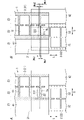
すなわち、図1に示すように、第1電極31は、第1マージン部211により、第1非分割電極41と、第1分割電極51と、に分離されている。第1分割電極51は、第1短手方向スリット部221により、複数の第1小電極群510に分割されている。複数の第1小電極群510の各々は、複数の第1小電極511を含む。複数の第1小電極511は、第1ヒューズ61で接続されている。
That is, as shown in FIG. 1, the first electrode 31 is separated into the first undivided electrode 41 and the first divided electrode 51 by the first margin portion 211 . The first divided electrode 51 is divided into a plurality of first small electrode groups 510 by first lateral direction slit portions 221 . Each of the multiple first small electrode groups 510 includes multiple first small electrodes 511 . A plurality of first small electrodes 511 are connected by a first fuse 61 .
一方、第2電極32は、第2マージン部212により、第2非分割電極42と、第2分割電極52と、に分離されている。第2分割電極52は、第2短手方向スリット部222により、複数の第2小電極群520に分割されている。複数の第2小電極群520の各々は、複数の第2小電極521を含む。複数の第2小電極521は、第2ヒューズ62で接続されている。
On the other hand, the second electrode 32 is separated into the second non-split electrode 42 and the second split electrode 52 by the second margin portion 212 . The second divided electrode 52 is divided into a plurality of second small electrode groups 520 by second lateral direction slit portions 222 . Each of the multiple second small electrode groups 520 includes multiple second small electrodes 521 . A plurality of second small electrodes 521 are connected by a second fuse 62 .
第1非分割電極41と左側の第2小電極521とが誘電体フィルム2を介して対向する部分(図1のZ1部分)に、1つ目の単位コンデンサ10が形成される。また左側の第1小電極511と右側の第2小電極521とが誘電体フィルム2を介して対向する部分(図1のZ2部分)に、2つ目の単位コンデンサ10が形成される。また右側の第1小電極511と第2非分割電極42とが誘電体フィルム2を介して対向する部分(図1のZ3部分)に、3つ目の単位コンデンサ10が形成される。これらの3つの単位コンデンサ10は、短手方向Sに直列に接続されている。
A first unit capacitor 10 is formed in a portion (Z1 portion in FIG. 1) where the first non-split electrode 41 and the second small electrode 521 on the left face each other with the dielectric film 2 interposed therebetween. A second unit capacitor 10 is formed in a portion (Z2 portion in FIG. 1) where the first small electrode 511 on the left side and the second small electrode 521 on the right side face each other with the dielectric film 2 interposed therebetween. A third unit capacitor 10 is formed in a portion (Z3 portion in FIG. 1) where the right first small electrode 511 and the second non-divided electrode 42 face each other with the dielectric film 2 interposed therebetween. These three unit capacitors 10 are connected in series in the lateral direction S. As shown in FIG.
さらに複数の第1小電極511は、第1ヒューズ61で接続されているとともに、複数の第2小電極521は、第2ヒューズ62で接続されているので、第1電極31及び第2電極32間の一部が短絡しても、第1ヒューズ61及び第2ヒューズ62の少なくともいずれかが切断される。
Further, since the plurality of first small electrodes 511 are connected by the first fuse 61 and the plurality of second small electrodes 521 are connected by the second fuse 62, the first electrode 31 and the second electrode 32 At least one of the first fuse 61 and the second fuse 62 is blown even if part of the gap is short-circuited.
したがって、本実施形態によれば、高電圧で使用しても、全体としての機能を保持することができる。ただし、本実施形態に係るフィルムコンデンサ1は、巻回型でも積層型でもよい。
Therefore, according to this embodiment, even when used at a high voltage, the function as a whole can be maintained. However, the film capacitor 1 according to this embodiment may be of the wound type or the laminated type.
2.詳細
(1)第1実施形態
以下、第1実施形態に係るフィルムコンデンサ1について、図面を参照して説明する。 2. Details (1) First Embodiment Hereinafter, afilm capacitor 1 according to a first embodiment will be described with reference to the drawings.
(1)第1実施形態
以下、第1実施形態に係るフィルムコンデンサ1について、図面を参照して説明する。 2. Details (1) First Embodiment Hereinafter, a
図1に示すように、フィルムコンデンサ1は、誘電体フィルム2と、第1電極31と、第2電極32と、を備える。
As shown in FIG. 1, the film capacitor 1 includes a dielectric film 2, a first electrode 31 and a second electrode 32.
フィルムコンデンサ1は、誘電体フィルム2(本実施形態では第1誘電体フィルム21)を介して第1電極31と第2電極32とが対向することで、短手方向Sに直列に接続された3つの単位コンデンサ10を含む(図9A参照)。
In the film capacitor 1, the first electrode 31 and the second electrode 32 face each other with the dielectric film 2 (in this embodiment, the first dielectric film 21) interposed therebetween, and are connected in series in the lateral direction S. It contains three unit capacitors 10 (see FIG. 9A).
以下、誘電体フィルム2、第1電極31、及び第2電極32について説明する。
The dielectric film 2, the first electrode 31, and the second electrode 32 will be described below.
<誘電体フィルム>
誘電体フィルム2は、誘電体により構成されたフィルムである。誘電体としては、特に限定されないが、例えば、ポリプロピレン(PP)及びポリエチレンテレフタレート(PET)等が挙げられる。 <Dielectric film>
Thedielectric film 2 is a film made of a dielectric. The dielectric is not particularly limited, but examples thereof include polypropylene (PP) and polyethylene terephthalate (PET).
誘電体フィルム2は、誘電体により構成されたフィルムである。誘電体としては、特に限定されないが、例えば、ポリプロピレン(PP)及びポリエチレンテレフタレート(PET)等が挙げられる。 <Dielectric film>
The
誘電体フィルム2は、細長いフィルム状をなす。すなわち、誘電体フィルム2は、短手方向Sに対して直交する長手方向Lに延びるフィルムである。
The dielectric film 2 has an elongated film shape. That is, the dielectric film 2 is a film extending in the longitudinal direction L orthogonal to the lateral direction S. As shown in FIG.
誘電体フィルム2は、第1面201と、第2面202と、を有する(図9A参照)。第1面201は、誘電体フィルム2の厚さ方向Tの一方側を向く面である。厚さ方向Tは、短手方向S及び長手方向Lに直交する方向である。第2面202は、第1面201の反対側の面である。すなわち、第2面202は、誘電体フィルム2の厚さ方向Tの他方側を向く面である。
The dielectric film 2 has a first surface 201 and a second surface 202 (see FIG. 9A). The first surface 201 is a surface facing one side in the thickness direction T of the dielectric film 2 . A thickness direction T is a direction orthogonal to the lateral direction S and the longitudinal direction L. As shown in FIG. The second surface 202 is the surface opposite to the first surface 201 . That is, the second surface 202 is a surface facing the other side in the thickness direction T of the dielectric film 2 .
本実施形態では、誘電体フィルム2は、第1誘電体フィルム21及び第2誘電体フィルム22を含む。
In this embodiment, the dielectric film 2 includes a first dielectric film 21 and a second dielectric film 22.
<第1電極>
第1電極31は、蒸着電極、金属箔電極、及びめっき電極のいずれでもよい。第1電極31の材質としては、特に限定されないが、例えば、アルミニウム等が挙げられる。 <First electrode>
Thefirst electrode 31 may be any of a vapor deposition electrode, a metal foil electrode, and a plated electrode. The material of the first electrode 31 is not particularly limited, but examples thereof include aluminum.
第1電極31は、蒸着電極、金属箔電極、及びめっき電極のいずれでもよい。第1電極31の材質としては、特に限定されないが、例えば、アルミニウム等が挙げられる。 <First electrode>
The
第1電極31は、誘電体フィルム2(本実施形態では第1誘電体フィルム21)の第1面201に配置されている。
The first electrode 31 is arranged on the first surface 201 of the dielectric film 2 (the first dielectric film 21 in this embodiment).
第1電極31は、第1マージン部211により、第1非分割電極41と、第1分割電極51と、に分離されている。
The first electrode 31 is separated into the first non-split electrode 41 and the first split electrode 51 by the first margin portion 211 .
第1マージン部211は、第1誘電体フィルム21の第1面201において、第1電極31が配置されていない部分である。したがって、この部分は、誘電体フィルム2が露出している。第1マージン部211は、一定の幅で長手方向Lに延びている。
The first margin portion 211 is a portion of the first surface 201 of the first dielectric film 21 where the first electrode 31 is not arranged. Therefore, the dielectric film 2 is exposed at this portion. The first margin portion 211 extends in the longitudinal direction L with a constant width.
第1非分割電極41は、長手方向Lに延びるベタ状をなす電極である。すなわち、第1非分割電極41は、第1マージン部211と、第1誘電体フィルム21の短手方向Sの一方側(左側)の端部との間の全体に配置されている。第1非分割電極41の左側端部は、第1端面電極310(図1では図示省略)と接続され得る。
The first undivided electrode 41 is a solid electrode extending in the longitudinal direction L. That is, the first non-divided electrode 41 is arranged entirely between the first margin portion 211 and the end portion on one side (left side) in the transverse direction S of the first dielectric film 21 . A left end portion of the first undivided electrode 41 can be connected to a first end face electrode 310 (not shown in FIG. 1).
一方、第1分割電極51は、第1マージン部211と第1端部マージン部241との間に配置されている。
On the other hand, the first split electrode 51 is arranged between the first margin portion 211 and the first end margin portion 241 .
ここで、第1端部マージン部241は、第1誘電体フィルム21の短手方向Sの他方側(右側)の端部に存在する。第1端部マージン部241も、第1マージン部211と同様に、第1電極31が配置されていない部分である。したがって、この部分も、誘電体フィルム2が露出している。第1端部マージン部241は、一定の幅で長手方向Lに延びている。第1端部マージン部241が存在することで、第1分割電極51と第2端面電極320(図1では図示省略)とは離間し得る。なお、本実施形態では、第1端部マージン部241の幅は、第1マージン部211の幅と同じであるが、本実施形態の効果を損なわない範囲で異なっていてもよい。
Here, the first end margin portion 241 exists at the end of the first dielectric film 21 on the other side (right side) in the transverse direction S. Similarly to the first margin portion 211, the first end margin portion 241 is also a portion where the first electrode 31 is not arranged. Therefore, the dielectric film 2 is also exposed in this portion. The first end margin portion 241 extends in the longitudinal direction L with a constant width. The presence of the first edge margin portion 241 allows the first split electrode 51 and the second edge electrode 320 (not shown in FIG. 1) to be separated from each other. In addition, in the present embodiment, the width of the first end margin portion 241 is the same as the width of the first margin portion 211, but may be different within a range that does not impair the effects of the present embodiment.
さらに第1分割電極51は、少なくとも1つ以上の第1短手方向スリット部221により、複数の第1小電極群510に分割されている。
Furthermore, the first divided electrode 51 is divided into a plurality of first small electrode groups 510 by at least one or more first lateral direction slit portions 221 .
第1短手方向スリット部221は、第1誘電体フィルム21の第1面201において、第1電極31が配置されていない部分である。したがって、この部分も、第1マージン部211及び第1端部マージン部241と同様に、誘電体フィルム2が露出している。第1短手方向スリット部221は、一定の幅で短手方向Sに延びている。第1短手方向スリット部221は、第1マージン部211及び第1端部マージン部241とつながっている。なお、本実施形態では、第1短手方向スリット部221の幅は、第1マージン部211の幅と同じであるが、本実施形態の効果を損なわない範囲で異なっていてもよい。
The first transverse direction slit portion 221 is a portion of the first surface 201 of the first dielectric film 21 where the first electrode 31 is not arranged. Accordingly, the dielectric film 2 is exposed in this portion as well as in the first margin portion 211 and the first end margin portion 241 . The first lateral direction slit portion 221 extends in the lateral direction S with a constant width. The first lateral direction slit portion 221 is connected to the first margin portion 211 and the first end margin portion 241 . In addition, in the present embodiment, the width of the first lateral direction slit portion 221 is the same as the width of the first margin portion 211, but may be different within a range that does not impair the effects of the present embodiment.
複数の第1小電極群510は、長手方向Lに並んでいる。複数の第1小電極群510の各々は、複数(本実施形態では2つ)の第1小電極511を含む。
The plurality of first small electrode groups 510 are arranged in the longitudinal direction L. Each of the multiple first small electrode groups 510 includes multiple (two in this embodiment) first small electrodes 511 .
複数の第1小電極511は、短手方向Sに並んでいる。本実施形態では、第1小電極511の形状は、矩形状であるが、特に限定されない。また本実施形態では、複数の第1小電極511の大きさが同じであるが、本実施形態の効果を損なわない範囲で異なっていてもよい。
The plurality of first small electrodes 511 are arranged in the lateral direction S. In this embodiment, the shape of the first small electrode 511 is rectangular, but is not particularly limited. Also, in this embodiment, the sizes of the plurality of first small electrodes 511 are the same, but they may be different as long as the effects of this embodiment are not impaired.
複数の第1小電極群510の各々に含まれる複数の第1小電極511は、第1ヒューズ61で接続されている。第1ヒューズ61は、過大な電流が流れると溶けて、回路を遮断する部分である。第1ヒューズ61は、短手方向Sに隣り合う第1小電極511同士を接続している。第1ヒューズ61の幅は、第1小電極511の長手方向Lの長さよりも短い。
A plurality of first small electrodes 511 included in each of the plurality of first small electrode groups 510 are connected by a first fuse 61 . The first fuse 61 is a part that melts when an excessive current flows to break the circuit. The first fuse 61 connects the first small electrodes 511 adjacent in the lateral direction S to each other. The width of the first fuse 61 is shorter than the length in the longitudinal direction L of the first small electrode 511 .
<第2電極>
第2電極32も、第1電極31と同様に、蒸着電極、金属箔電極、及びめっき電極のいずれでもよい。第2電極32の材質も第1電極31の材質と同様である。 <Second electrode>
As with thefirst electrode 31, the second electrode 32 may also be any of a vapor deposition electrode, a metal foil electrode, and a plated electrode. The material of the second electrode 32 is also the same as the material of the first electrode 31 .
第2電極32も、第1電極31と同様に、蒸着電極、金属箔電極、及びめっき電極のいずれでもよい。第2電極32の材質も第1電極31の材質と同様である。 <Second electrode>
As with the
第2電極32は、誘電体フィルム2(本実施形態では第1誘電体フィルム21)の第2面202に配置されている。換言すれば、本実施形態では、第2電極32は、第2誘電体フィルム22の第1面201に配置されている。
The second electrode 32 is arranged on the second surface 202 of the dielectric film 2 (the first dielectric film 21 in this embodiment). In other words, the second electrode 32 is arranged on the first surface 201 of the second dielectric film 22 in this embodiment.
第2電極32は、第2マージン部212により、第2非分割電極42と、第2分割電極52と、に分離されている。
The second electrode 32 is separated into a second non-split electrode 42 and a second split electrode 52 by a second margin portion 212 .
第2マージン部212は、第2誘電体フィルム22の第1面201において、第2電極32が配置されていない部分である。したがって、この部分は、誘電体フィルム2が露出している。第2マージン部212は、一定の幅で長手方向Lに延びている。なお、本実施形態では、第2マージン部212の幅は、第1マージン部211の幅と同じであるが、本実施形態の効果を損なわない範囲で異なっていてもよい。
The second margin portion 212 is a portion of the first surface 201 of the second dielectric film 22 where the second electrode 32 is not arranged. Therefore, the dielectric film 2 is exposed at this portion. The second margin portion 212 extends in the longitudinal direction L with a constant width. In addition, in the present embodiment, the width of the second margin portion 212 is the same as the width of the first margin portion 211, but may be different within a range that does not impair the effects of the present embodiment.
第2非分割電極42は、長手方向Lに延びるベタ状をなす電極である。すなわち、第2非分割電極42は、第2マージン部212と、第2誘電体フィルム22の短手方向Sの他方側(右側)の端部との間の全体に配置されている。第2非分割電極42の右側端部は、第2端面電極320と接続され得る。
The second non-split electrode 42 is a solid electrode extending in the longitudinal direction L. That is, the second non-divided electrode 42 is arranged entirely between the second margin portion 212 and the other (right) end of the second dielectric film 22 in the transverse direction S. As shown in FIG. The right end of the second non-split electrode 42 can be connected to the second edge electrode 320 .
一方、第2分割電極52は、第2マージン部212と第2端部マージン部242との間に配置されている。
On the other hand, the second split electrode 52 is arranged between the second margin portion 212 and the second end margin portion 242 .
ここで、第2端部マージン部242は、第2誘電体フィルム22の短手方向Sの一方側(左側)の端部に存在する。第2端部マージン部242も、第2マージン部212と同様に、第2電極32が配置されていない部分である。したがって、この部分も、誘電体フィルム2が露出している。第2端部マージン部242は、一定の幅で長手方向Lに延びている。第2端部マージン部242が存在することで、第2分割電極52と第1端面電極310とは離間し得る。なお、本実施形態では、第2端部マージン部242の幅は、第2マージン部212の幅と同じであるが、本実施形態の効果を損なわない範囲で異なっていてもよい。
Here, the second edge margin portion 242 exists at one side (left side) edge in the transverse direction S of the second dielectric film 22 . Similarly to the second margin portion 212, the second end margin portion 242 is also a portion where the second electrode 32 is not arranged. Therefore, the dielectric film 2 is also exposed in this portion. The second end margin portion 242 extends in the longitudinal direction L with a constant width. The presence of the second end margin portion 242 allows the second split electrode 52 and the first end face electrode 310 to be separated from each other. In addition, in the present embodiment, the width of the second end margin portion 242 is the same as the width of the second margin portion 212, but may be different within a range that does not impair the effects of the present embodiment.
さらに第2分割電極52は、少なくとも1つ以上の第2短手方向スリット部222により、複数の第2小電極群520に分割されている。
Furthermore, the second divided electrode 52 is divided into a plurality of second small electrode groups 520 by at least one or more second lateral direction slit portions 222 .
第2短手方向スリット部222は、第2誘電体フィルム22の第1面201において、第2電極32が配置されていない部分である。したがって、この部分も、第2マージン部212及び第2端部マージン部242と同様に、誘電体フィルム2が露出している。第2短手方向スリット部222は、一定の幅で短手方向Sに延びている。第2短手方向スリット部222は、第2マージン部212及び第2端部マージン部242とつながっている。なお、本実施形態では、第2短手方向スリット部222の幅は、第2マージン部212の幅と同じであるが、本実施形態の効果を損なわない範囲で異なっていてもよい。さらに本実施形態では、第2短手方向スリット部222の幅は、第1短手方向スリット部221の幅と同じであるが、本実施形態の効果を損なわない範囲で異なっていてもよい。
The second lateral direction slit portion 222 is a portion of the first surface 201 of the second dielectric film 22 where the second electrode 32 is not arranged. Accordingly, the dielectric film 2 is exposed in this portion as well as the second margin portion 212 and the second end margin portion 242 . The second transverse direction slit portion 222 extends in the transverse direction S with a constant width. The second lateral direction slit portion 222 is connected to the second margin portion 212 and the second end margin portion 242 . In addition, in the present embodiment, the width of the second lateral direction slit portion 222 is the same as the width of the second margin portion 212, but may be different within a range that does not impair the effects of the present embodiment. Furthermore, in the present embodiment, the width of the second transverse direction slit portion 222 is the same as the width of the first transverse direction slit portion 221, but may differ within a range that does not impair the effects of the present embodiment.
複数の第2小電極群520は、長手方向Lに並んでいる。複数の第2小電極群520の各々は、複数(本実施形態では2つ)の第2小電極521を含む。
The plurality of second small electrode groups 520 are arranged in the longitudinal direction L. Each of the multiple second small electrode groups 520 includes multiple (two in this embodiment) second small electrodes 521 .
複数の第2小電極521は、短手方向Sに並んでいる。本実施形態では、第2小電極521の形状は、矩形状であるが、特に限定されない。また本実施形態では、複数の第2小電極521の大きさが同じであるが、本実施形態の効果を損なわない範囲で異なっていてもよい。さらに本実施形態では、第2小電極521の形状及び大きさが第1小電極511の形状及び大きさと同じであるが、本実施形態の効果を損なわない範囲で異なっていてもよい。
The plurality of second small electrodes 521 are arranged in the lateral direction S. In this embodiment, the shape of the second small electrode 521 is rectangular, but is not particularly limited. In addition, although the sizes of the plurality of second small electrodes 521 are the same in this embodiment, they may be different as long as the effects of this embodiment are not impaired. Furthermore, in this embodiment, the shape and size of the second small electrode 521 are the same as the shape and size of the first small electrode 511, but they may be different as long as the effects of this embodiment are not impaired.
複数の第2小電極群520の各々に含まれる複数の第2小電極521は、第2ヒューズ62で接続されている。第2ヒューズ62も、第1ヒューズ61と同様に、過大な電流が流れると溶けて、回路を遮断する部分である。第2ヒューズ62は、短手方向Sに隣り合う第2小電極521同士を接続している。第2ヒューズ62の幅は、第2小電極521の長手方向Lの長さよりも短い。
A plurality of second small electrodes 521 included in each of the plurality of second small electrode groups 520 are connected by a second fuse 62 . Like the first fuse 61, the second fuse 62 is also a part that melts when an excessive current flows to cut off the circuit. The second fuse 62 connects the second small electrodes 521 adjacent to each other in the lateral direction S. As shown in FIG. The width of the second fuse 62 is shorter than the length in the longitudinal direction L of the second small electrode 521 .
以上説明した第2電極32は、誘電体フィルム2(本実施形態では第1誘電体フィルム21)を介して第1電極31と対向している。
The second electrode 32 described above faces the first electrode 31 via the dielectric film 2 (the first dielectric film 21 in this embodiment).
具体的には、第2電極32の第2分割電極52が、誘電体フィルム2を介して、第1電極31の第1非分割電極41と対向する部分(図1のZ1部分)が存在する。より詳細に言えば、第2電極32の左側の第2小電極521は、誘電体フィルム2を介して、第1電極31の第1非分割電極41と対向している。この部分に1つ目の単位コンデンサ10が形成される。
Specifically, there is a portion (Z1 portion in FIG. 1) where the second split electrode 52 of the second electrode 32 faces the first non-split electrode 41 of the first electrode 31 through the dielectric film 2. . More specifically, the second small electrode 521 on the left side of the second electrode 32 faces the first undivided electrode 41 of the first electrode 31 with the dielectric film 2 interposed therebetween. A first unit capacitor 10 is formed in this portion.
また第2電極32の第2分割電極52が、誘電体フィルム2を介して、第1電極31の第1分割電極51と対向する部分(図1のZ2部分)が存在する。より詳細に言えば、第2電極32の右側の第2小電極521は、誘電体フィルム2を介して、第1電極31の左側の第1小電極511と対向している。この部分に2つ目の単位コンデンサ10が形成される。
There is also a portion (Z2 portion in FIG. 1) where the second split electrode 52 of the second electrode 32 faces the first split electrode 51 of the first electrode 31 with the dielectric film 2 interposed therebetween. More specifically, the second small electrode 521 on the right side of the second electrode 32 faces the first small electrode 511 on the left side of the first electrode 31 with the dielectric film 2 interposed therebetween. A second unit capacitor 10 is formed in this portion.
また第2電極32の第2非分割電極42が、誘電体フィルム2を介して、第1電極31の第1分割電極51と対向する部分(図1のZ3部分)が存在する。より詳細に言えば、第2電極32の第2非分割電極42は、誘電体フィルム2を介して、第1電極31の右側の第1小電極511と対向している。この部分に3つ目の単位コンデンサ10が形成される。
There is also a portion (Z3 portion in FIG. 1) where the second non-split electrode 42 of the second electrode 32 faces the first split electrode 51 of the first electrode 31 with the dielectric film 2 interposed therebetween. More specifically, the second non-divided electrode 42 of the second electrode 32 faces the first small electrode 511 on the right side of the first electrode 31 with the dielectric film 2 interposed therebetween. A third unit capacitor 10 is formed in this portion.
<作用効果>
本実施形態によれば、フィルムコンデンサ1を高電圧で使用しても、全体としての機能を保持することができる。 <Effect>
According to this embodiment, even if thefilm capacitor 1 is used at a high voltage, the function as a whole can be maintained.
本実施形態によれば、フィルムコンデンサ1を高電圧で使用しても、全体としての機能を保持することができる。 <Effect>
According to this embodiment, even if the
すなわち、本実施形態に係るフィルムコンデンサ1は、図9Aに示すフィルムコンデンサ1と同様に、誘電体フィルム2の短手方向Sに直列に接続された3つの単位コンデンサ10を含む。そのため、図7A及び図8Aに示すフィルムコンデンサ1の第1端面電極310及び第2端面電極320間に印加される電圧と、本実施形態に係るフィルムコンデンサ1の第1端面電極310及び第2端面電極320間に印加される電圧とが同じである場合、図7A及び図8Aに示すフィルムコンデンサ1の単位コンデンサ10に印加される電圧よりも、本実施形態に係るフィルムコンデンサ1の単位コンデンサ10に印加される電圧の方が小さくなることにより、誘電体フィルム2の損傷を更に抑制しやすくなる。
That is, the film capacitor 1 according to this embodiment includes three unit capacitors 10 connected in series in the transverse direction S of the dielectric film 2, like the film capacitor 1 shown in FIG. 9A. Therefore, the voltage applied between the first end surface electrode 310 and the second end surface electrode 320 of the film capacitor 1 shown in FIGS. 7A and 8A and the first end surface electrode 310 and the second end surface of the film capacitor 1 according to the present embodiment When the voltage applied between the electrodes 320 is the same, the voltage applied to the unit capacitor 10 of the film capacitor 1 according to the present embodiment is higher than the voltage applied to the unit capacitor 10 of the film capacitor 1 shown in FIGS. 7A and 8A. By reducing the applied voltage, it becomes easier to suppress damage to the dielectric film 2 .
さらに本実施形態に係るフィルムコンデンサ1では、図1に示すように、複数の第1小電極511は、第1ヒューズ61で接続されているとともに、複数の第2小電極521は、第2ヒューズ62で接続されている。そのため、第1電極31及び第2電極32間の一部が短絡しても、第1ヒューズ61及び第2ヒューズ62の少なくともいずれかが切断される。
Furthermore, in the film capacitor 1 according to this embodiment, as shown in FIG. 1, the plurality of first small electrodes 511 are connected by the first fuse 61, and the plurality of second small electrodes 521 are connected by the second fuse. 62 are connected. Therefore, even if a part between the first electrode 31 and the second electrode 32 is short-circuited, at least one of the first fuse 61 and the second fuse 62 is disconnected.
したがって、本実施形態によれば、フィルムコンデンサ1を高電圧で使用しても、全体としての機能を保持することができる。
Therefore, according to this embodiment, even if the film capacitor 1 is used at a high voltage, the function as a whole can be maintained.
(2)第2実施形態
次に、第2実施形態に係るフィルムコンデンサ1について、図面を参照して説明する。第2実施形態では、第1実施形態と同様の構成要素には第1実施形態と同一の符号を付して詳細な説明を省略する場合がある。 (2) Second Embodiment Next, afilm capacitor 1 according to a second embodiment will be described with reference to the drawings. In the second embodiment, the same reference numerals as in the first embodiment may be assigned to the same components as in the first embodiment, and detailed description thereof may be omitted.
次に、第2実施形態に係るフィルムコンデンサ1について、図面を参照して説明する。第2実施形態では、第1実施形態と同様の構成要素には第1実施形態と同一の符号を付して詳細な説明を省略する場合がある。 (2) Second Embodiment Next, a
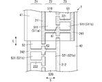
図2Bに示す第2実施形態に係るフィルムコンデンサ1には、図2Aに示す第1実施形態に係るフィルムコンデンサ1と同様に、誘電体フィルム2を介して、第1非分割電極41と第2分割電極52とが対向する部分(Z1部分)と、第1分割電極51と第2分割電極52とが対向する部分(Z2部分)と、第1分割電極51と第2非分割電極42とが対向する部分(Z3部分)と、が存在する。
In the film capacitor 1 according to the second embodiment shown in FIG. 2B, the first non-divided electrode 41 and the second electrode 41 are arranged via the dielectric film 2, similarly to the film capacitor 1 according to the first embodiment shown in FIG. 2A. A portion (Z1 portion) facing the divided electrode 52, a portion (Z2 portion) facing the first divided electrode 51 and the second divided electrode 52, and the first divided electrode 51 and the second non-divided electrode 42. A facing portion (Z3 portion) exists.
≪第1短手方向スリット部≫
本実施形態に係るフィルムコンデンサ1は、第1短手方向スリット部221の幅が場所によって異なる点で、第1実施形態に係るフィルムコンデンサ1と相違する。以下、この点について説明する。 <<First transverse direction slit part>>
Thefilm capacitor 1 according to the present embodiment differs from the film capacitor 1 according to the first embodiment in that the width of the first lateral direction slit portion 221 differs depending on the location. This point will be described below.
本実施形態に係るフィルムコンデンサ1は、第1短手方向スリット部221の幅が場所によって異なる点で、第1実施形態に係るフィルムコンデンサ1と相違する。以下、この点について説明する。 <<First transverse direction slit part>>
The
図2Aに示すように、第1実施形態に係るフィルムコンデンサ1では、第1分割電極51と第2分割電極52とが対向する部分(Z2部分)における第1短手方向スリット部221の幅と、第1分割電極51と第2非分割電極42とが対向する部分(Z3部分)における第1短手方向スリット部221の幅とが同じである。
As shown in FIG. 2A, in the film capacitor 1 according to the first embodiment, the width and , and the width of the first transverse direction slit portion 221 at the portion (Z3 portion) where the first split electrode 51 and the second non-split electrode 42 face each other.
ところで、単位コンデンサ10は、第1電極31と第2電極32とが対向する部分に形成されるが、第1電極31と第2電極32とが対向しない部分には形成されない。例えば、第1電極31と第2短手方向スリット部222とが対向している部分には、単位コンデンサ10は形成されない(一点鎖線で囲まれたXa部分参照)。同様に、第1短手方向スリット部221と第2電極32とが対向している部分にも、単位コンデンサ10は形成されない(Xa部分参照)。
By the way, the unit capacitor 10 is formed in the portion where the first electrode 31 and the second electrode 32 face each other, but is not formed in the portion where the first electrode 31 and the second electrode 32 do not face each other. For example, the unit capacitor 10 is not formed in the portion where the first electrode 31 and the second lateral direction slit portion 222 face each other (see the Xa portion surrounded by the dashed-dotted line). Similarly, the unit capacitor 10 is not formed in the portion where the first lateral direction slit portion 221 and the second electrode 32 face each other (see portion Xa).
したがって、特に第1分割電極51と第2分割電極52とが対向する部分(Z2部分)においては、第1短手方向スリット部221と第2短手方向スリット部222とが対向しない場合に比べて、これらが対向する場合の方が理想的である。より詳細には、第1短手方向スリット部221と第2短手方向スリット部222とが対向する面積が大きいほど理想的である。なぜなら、第1短手方向スリット部221と第2短手方向スリット部222とが対向しないと、これらの幅に相当する分だけZ2部分における単位コンデンサ10の容量が低下するからである。逆に言えば、Z2部分においては、第1短手方向スリット部221と第2短手方向スリット部222とが対向する面積が大きくなるほど、相対的に単位コンデンサ10の電極面積(第1電極31と第2電極32とが対向する面積)が大きくなるので、単位コンデンサ10の容量の低下を抑制することができる。
Therefore, particularly in the portion (Z2 portion) where the first split electrode 51 and the second split electrode 52 face each other, compared to the case where the first width direction slit portion 221 and the second width direction slit portion 222 do not face each other, ideally if they are opposite each other. More specifically, it is ideal that the area where the first transverse direction slit portion 221 and the second transverse direction slit portion 222 face each other is large. This is because the capacity of the unit capacitor 10 in the Z2 portion decreases by the amount corresponding to the widths of the first lateral direction slit portion 221 and the second lateral direction slit portion 222 if they do not face each other. Conversely, in the Z2 portion, the electrode area of the unit capacitor 10 (the first electrode 31 and the second electrode 32) is increased, the decrease in the capacity of the unit capacitor 10 can be suppressed.
上記のような問題は、第1非分割電極41と第2分割電極52とが対向する部分(Z1部分)、及び第1分割電極51と第2非分割電極42とが対向する部分(Z3部分)においては、ほぼ生じない。なぜなら、Z1部分においては、第1非分割電極41はベタ状をなす電極であることから、第1非分割電極41と対向する第2短手方向スリット部222が長手方向Lにおいてどの位置に存在しても、Z1部分における単位コンデンサ10の容量はほぼ変化しないからである。Z3部分についても同様である。
The above problems are caused by the portion (Z1 portion) where the first undivided electrode 41 and the second undivided electrode 52 face each other and the portion (Z3 portion) where the first divided electrode 51 and the second undivided electrode 42 face each other. ), it almost never occurs. This is because, in the Z1 portion, since the first undivided electrode 41 is a solid electrode, at which position in the longitudinal direction L the second lateral slit portion 222 facing the first undivided electrode 41 exists. This is because the capacitance of the unit capacitor 10 in the Z1 portion does not substantially change. The same applies to the Z3 portion.
一方で、第1分割電極51と第2分割電極52とが対向する部分(Z2部分)においては、第1短手方向スリット部221と第2短手方向スリット部222とが対向することが理想的であるが、実際には第1短手方向スリット部221と第2短手方向スリット部222とが対向しない場合があり得る。その理由の1つとして、図10に示すように、2枚の誘電体フィルム2(第1誘電体フィルム21及び第2誘電体フィルム22)を重ねて巻回することが挙げられる。この場合、第1電極31と第2電極32とは厚さ方向Tにおいて誘電体フィルム2の厚さ分だけ離れているため、2枚の誘電体フィルム2を重ねて巻回すると、巻回方向(長手方向L)に沿って第1電極31と第2電極32とが少しずつずれていく。これにより、第1短手方向スリット部221と第2短手方向スリット部222とが対向しないことが起こり得る。そうすると、最大で、第1短手方向スリット部221及び第2短手方向スリット部222の幅の和に相当する分だけ(Xa部分)、Z2部分における単位コンデンサ10の容量が低下し、Z1及びZ3部分における単位コンデンサ10の容量と異なり得る。したがって、フィルムコンデンサ1の第1端面電極310及び第2端面電極320間に電圧を印加した場合、短手方向Sに直列に接続された3つの単位コンデンサ10に印加される電圧が不均一になり得る。
On the other hand, in the portion (Z2 portion) where the first split electrode 51 and the second split electrode 52 face each other, it is ideal that the first width direction slit portion 221 and the second width direction slit portion 222 face each other. However, in practice, there may be a case where the first transverse direction slit portion 221 and the second transverse direction slit portion 222 do not face each other. One of the reasons for this is that two dielectric films 2 (first dielectric film 21 and second dielectric film 22) are stacked and wound as shown in FIG. In this case, since the first electrode 31 and the second electrode 32 are separated by the thickness of the dielectric film 2 in the thickness direction T, when the two dielectric films 2 are stacked and wound, the winding direction The first electrode 31 and the second electrode 32 shift little by little along the (longitudinal direction L). As a result, the first transverse direction slit portion 221 and the second transverse direction slit portion 222 may not face each other. Then, the capacity of the unit capacitor 10 at the Z2 portion is reduced by a maximum amount corresponding to the sum of the widths of the first transverse direction slit portion 221 and the second transverse direction slit portion 222 (Xa portion), and Z1 and It can be different from the capacitance of the unit capacitor 10 in the Z3 portion. Therefore, when a voltage is applied between the first end surface electrode 310 and the second end surface electrode 320 of the film capacitor 1, the voltage applied to the three unit capacitors 10 connected in series in the lateral direction S becomes uneven. obtain.
そこで、図2Bに示す第2実施形態に係るフィルムコンデンサ1では、第1分割電極51と第2分割電極52とが対向する部分(Z2部分)における第1短手方向スリット部221の幅Wa1を、第1分割電極51と第2非分割電極42とが対向する部分(Z3部分)における第1短手方向スリット部221の幅Wb1よりも小さくしている(Wa1<Wb1)。これにより、Z2部分における第1電極31の面積が相対的に増加するので、第1短手方向スリット部221と第2短手方向スリット部222とが対向しない場合があっても、Z2部分における単位コンデンサ10の容量の低下を抑制することができる。
Therefore, in the film capacitor 1 according to the second embodiment shown in FIG. 2B, the width Wa1 of the first lateral direction slit portion 221 at the portion (Z2 portion) where the first split electrode 51 and the second split electrode 52 face each other is set to , the width Wb1 of the first lateral direction slit portion 221 at the portion (Z3 portion) where the first split electrode 51 and the second non-split electrode 42 face each other (Wa1<Wb1). As a result, the area of the first electrode 31 in the Z2 portion relatively increases, so even if the first transverse direction slit portion 221 and the second transverse direction slit portion 222 do not face each other, the Z2 portion A decrease in the capacity of the unit capacitor 10 can be suppressed.
≪第2短手方向スリット部≫
さらに本実施形態に係るフィルムコンデンサ1は、第2短手方向スリット部222の幅が場所によって異なる点で、第1実施形態に係るフィルムコンデンサ1と相違する。以下、この点について説明するが、第2短手方向スリット部222についても、上述の第1短手方向スリット部221と同様の考え方が当てはまる。 <<Second transverse direction slit part>>
Furthermore, thefilm capacitor 1 according to the present embodiment differs from the film capacitor 1 according to the first embodiment in that the width of the second lateral direction slit portion 222 differs depending on the location. This point will be described below, but the same idea as the above-described first lateral direction slit portion 221 applies to the second lateral direction slit portion 222 as well.
さらに本実施形態に係るフィルムコンデンサ1は、第2短手方向スリット部222の幅が場所によって異なる点で、第1実施形態に係るフィルムコンデンサ1と相違する。以下、この点について説明するが、第2短手方向スリット部222についても、上述の第1短手方向スリット部221と同様の考え方が当てはまる。 <<Second transverse direction slit part>>
Furthermore, the
すなわち、図2Bに示す第2実施形態に係るフィルムコンデンサ1では、第1分割電極51と第2分割電極52とが対向する部分(Z2部分)における第2短手方向スリット部222の幅Wa2を、第1非分割電極41と第2分割電極52とが対向する部分(Z1部分)における第2短手方向スリット部222の幅Wb2よりも小さくしている(Wa2<Wb2)。これにより、Z2部分における第2電極32の面積が相対的に増加するので、第1短手方向スリット部221と第2短手方向スリット部222とが対向しない場合があっても、Z2部分における単位コンデンサ10の容量の低下を更に抑制することができる。
That is, in the film capacitor 1 according to the second embodiment shown in FIG. 2B, the width Wa2 of the second lateral direction slit portion 222 at the portion (Z2 portion) where the first split electrode 51 and the second split electrode 52 face each other is , the width Wb2 of the second lateral direction slit portion 222 at the portion (Z1 portion) where the first non-split electrode 41 and the second split electrode 52 face each other (Wa2<Wb2). As a result, the area of the second electrode 32 in the Z2 portion is relatively increased. A decrease in the capacity of the unit capacitor 10 can be further suppressed.
≪第1短手方向スリット部及び第2短手方向スリット部≫
本実施形態では、Z2及びZ3部分における第1短手方向スリット部221と、Z1及びZ2部分における第2短手方向スリット部222との関係も規定している。 <<First transverse direction slit part and second transverse direction slit part>>
In this embodiment, the relationship between the first transverse direction slitportions 221 in the Z2 and Z3 portions and the second transverse direction slit portions 222 in the Z1 and Z2 portions is also defined.
本実施形態では、Z2及びZ3部分における第1短手方向スリット部221と、Z1及びZ2部分における第2短手方向スリット部222との関係も規定している。 <<First transverse direction slit part and second transverse direction slit part>>
In this embodiment, the relationship between the first transverse direction slit
すなわち、図2Bに示すように、第1分割電極51と第2分割電極52とが対向する部分(Z2部分)における第1短手方向スリット部221の幅Wa1及び第2短手方向スリット部222の幅Wa2の和が、第1分割電極51と第2非分割電極42とが対向する部分(Z3部分)における第1短手方向スリット部221の幅Wb1、及び第1非分割電極41と第2分割電極52とが対向する部分(Z1部分)における第2短手方向スリット部222の幅Wb2の少なくともいずれかに等しい。
That is, as shown in FIG. 2B, the width Wa1 of the first lateral direction slit portion 221 and the second lateral direction slit portion 222 at the portion (Z2 portion) where the first split electrode 51 and the second split electrode 52 face is the width Wb1 of the first lateral direction slit portion 221 at the portion (Z3 portion) where the first split electrode 51 and the second unsplit electrode 42 face each other, and the width Wb1 of the first short-side direction slit portion 221, It is equal to at least one of the width Wb2 of the second lateral direction slit portion 222 in the portion (Z1 portion) facing the two-split electrode 52 .
上記のZ2及びZ3部分における第1短手方向スリット部221と、Z1及びZ2部分における第2短手方向スリット部222との関係を数式で表すと、以下の(1)~(3)のいずれかである。
The relationship between the first transverse direction slit portions 221 in the Z2 and Z3 portions and the second transverse direction slit portions 222 in the Z1 and Z2 portions can be expressed by any of the following (1) to (3) or
(1)Wa1+Wa2=Wb1
(2)Wa1+Wa2=Wb2
(3)Wa1+Wa2=Wb1=Wb2。 (1) Wa1+Wa2=Wb1
(2) Wa1+Wa2=Wb2
(3) Wa1+Wa2=Wb1=Wb2.
(2)Wa1+Wa2=Wb2
(3)Wa1+Wa2=Wb1=Wb2。 (1) Wa1+Wa2=Wb1
(2) Wa1+Wa2=Wb2
(3) Wa1+Wa2=Wb1=Wb2.
本実施形態では、Z3部分における第1短手方向スリット部221の幅Wb1と、Z1部分における第2短手方向スリット部222の幅Wb2とが等しい。したがって、本実施形態では、特に上記(3)の数式が当てはまる。なお、本実施形態の効果を損なわなければ、Wa1とWa2との和は、Wb1と厳密に等しくなくてもよいし、またWb2と厳密に等しくなくてもよい。
In this embodiment, the width Wb1 of the first lateral direction slit portion 221 in the Z3 portion and the width Wb2 of the second lateral direction slit portion 222 in the Z1 portion are equal. Therefore, in this embodiment, the above formula (3) applies in particular. Note that the sum of Wa1 and Wa2 does not have to be exactly equal to Wb1 or Wb2, as long as the effect of the present embodiment is not impaired.
上記(1)の数式が成り立つ場合、少なくともZ2及びZ3部分における単位コンデンサ10に印加される電圧が不均一になりにくくなる。Z2部分における単位コンデンサ10の容量の低下が最大となるのは、第1短手方向スリット部221と第2短手方向スリット部222とが全く対向しない場合である(一点鎖線で囲まれたXb部分参照)。この場合、第1短手方向スリット部221及び第2短手方向スリット部222の幅の和(Wa1+Wa2)に相当する分だけ、Z2部分における単位コンデンサ10の容量が低下する。しかしながら、Z2部分における第1短手方向スリット部221及び第2短手方向スリット部222の幅の和(Wa1+Wa2)は、Z3部分における第1短手方向スリット部221の幅(Wb1)に等しい。この幅(Wb1)に相当する分は、もともとZ3部分において単位コンデンサ10が形成されない。したがって、少なくともZ2及びZ3部分における単位コンデンサ10に印加される電圧は不均一になりにくい。
When the above formula (1) holds, the voltage applied to the unit capacitors 10 at least in the Z2 and Z3 portions is less likely to be uneven. The decrease in the capacity of the unit capacitor 10 at the Z2 portion is maximized when the first transverse direction slit portion 221 and the second transverse direction slit portion 222 do not face each other at all (Xb part). In this case, the capacity of the unit capacitor 10 at the Z2 portion is reduced by the sum (Wa1+Wa2) of the widths of the first transverse direction slit portion 221 and the second transverse direction slit portion 222 . However, the sum (Wa1+Wa2) of the widths of the first transverse direction slit portion 221 and the second transverse direction slit portion 222 in the Z2 portion is equal to the width (Wb1) of the first transverse direction slit portion 221 in the Z3 portion. The unit capacitor 10 is not originally formed in the Z3 portion corresponding to this width (Wb1). Therefore, the voltages applied to the unit capacitors 10 at least in the Z2 and Z3 portions are less likely to be uneven.
上記と同様の考え方で、上記(2)の数式が成り立つ場合、少なくともZ1及びZ2部分における単位コンデンサ10に印加される電圧が不均一になりにくくなる。さらに上記(3)の数式が成り立つ場合、Z1~Z3部分における単位コンデンサ10に印加される電圧が不均一になりにくくなる。
In the same way of thinking as above, when the above formula (2) holds true, the voltage applied to the unit capacitors 10 at least in the Z1 and Z2 portions is less likely to become non-uniform. Furthermore, when the above formula (3) holds true, the voltage applied to the unit capacitor 10 in the Z1 to Z3 portions is less likely to be non-uniform.
<作用効果>
本実施形態によれば、第1実施形態と同様の作用効果に加えて、以下のような作用効果も奏する。 <Effect>
According to this embodiment, in addition to the same effects as those of the first embodiment, the following effects are also achieved.
本実施形態によれば、第1実施形態と同様の作用効果に加えて、以下のような作用効果も奏する。 <Effect>
According to this embodiment, in addition to the same effects as those of the first embodiment, the following effects are also achieved.
すなわち、本実施形態では、Z2部分における第1短手方向スリット部221の幅Wa1がZ3部分における第1短手方向スリット部221の幅Wb1よりも小さく(Wa1<Wb1)、Z2部分における第2短手方向スリット部222の幅Wa2がZ1部分における第2短手方向スリット部222の幅Wb2よりも小さい(Wa2<Wb2)。
That is, in the present embodiment, the width Wa1 of the first lateral direction slit portion 221 in the Z2 portion is smaller than the width Wb1 of the first lateral direction slit portion 221 in the Z3 portion (Wa1<Wb1), and the second width in the Z2 portion The width Wa2 of the lateral direction slit portion 222 is smaller than the width Wb2 of the second lateral direction slit portion 222 at the Z1 portion (Wa2<Wb2).
そのため、Z2部分において第1短手方向スリット部221と第2短手方向スリット部222とが厚さ方向Tにおいて対向せずに長手方向Lにずれていても、Z2部分における単位コンデンサ10の電極面積は、Z1及びZ3部分における単位コンデンサ10の電極面積から大きく外れなくなる。
Therefore, even if the first transverse direction slit portion 221 and the second transverse direction slit portion 222 in the Z2 portion do not face each other in the thickness direction T and are shifted in the longitudinal direction L, the electrodes of the unit capacitor 10 in the Z2 portion The area does not largely deviate from the electrode area of the unit capacitor 10 in the Z1 and Z3 portions.
したがって、本実施形態によれば、フィルムコンデンサ1の第1端面電極310及び第2端面電極320間に電圧を印加した場合、短手方向Sに直列に接続された3つの単位コンデンサ10に印加される電圧が不均一になりにくい。換言すれば、特定の単位コンデンサに印加される電圧が極端に大きくなることを抑制することができる。
Therefore, according to this embodiment, when a voltage is applied between the first end surface electrode 310 and the second end surface electrode 320 of the film capacitor 1, the voltage is applied to the three unit capacitors 10 connected in series in the lateral direction S. The voltage applied is less likely to be uneven. In other words, it is possible to prevent the voltage applied to a specific unit capacitor from becoming excessively large.
(3)第3実施形態
次に、第3実施形態に係るフィルムコンデンサ1について、図面を参照して説明する。第3実施形態では、第1~2実施形態と同様の構成要素には第1~2実施形態と同一の符号を付して詳細な説明を省略する場合がある。 (3) Third Embodiment Next, afilm capacitor 1 according to a third embodiment will be described with reference to the drawings. In the third embodiment, components similar to those in the first and second embodiments are given the same reference numerals as those in the first and second embodiments, and detailed description thereof may be omitted.
次に、第3実施形態に係るフィルムコンデンサ1について、図面を参照して説明する。第3実施形態では、第1~2実施形態と同様の構成要素には第1~2実施形態と同一の符号を付して詳細な説明を省略する場合がある。 (3) Third Embodiment Next, a
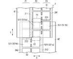
図3及び図4に示す第3実施形態に係るフィルムコンデンサ1には、第1実施形態に係るフィルムコンデンサ1と同様に、誘電体フィルム2を介して、第1非分割電極41と第2分割電極52とが対向する部分(Z1部分)と、第1分割電極51と第2分割電極52とが対向する部分(Z2部分)と、第1分割電極51と第2非分割電極42とが対向する部分(Z3部分)と、が存在する。
The film capacitor 1 according to the third embodiment shown in FIGS. 3 and 4 includes a first non-divided electrode 41 and a second divided electrode 41 via the dielectric film 2 in the same manner as the film capacitor 1 according to the first embodiment. A portion (Z1 portion) facing the electrode 52, a portion (Z2 portion) facing the first divided electrode 51 and the second divided electrode 52, and a portion (Z2 portion) facing the first divided electrode 51 and the second non-divided electrode 42. There is a part (Z3 part) that does.
≪第1短手方向スリット部≫
本実施形態に係るフィルムコンデンサ1は、第1短手方向スリット部221の数が場所によって異なる点で、第1実施形態に係るフィルムコンデンサ1と相違する。本実施形態では、第2実施形態で述べた問題を、第1短手方向スリット部221の数を場所によって変えることで解決しようとしている。以下、この点について説明する。 <<First transverse direction slit part>>
Thefilm capacitor 1 according to the present embodiment is different from the film capacitor 1 according to the first embodiment in that the number of first lateral direction slit portions 221 differs depending on the location. In this embodiment, the problem described in the second embodiment is to be solved by changing the number of first lateral direction slit portions 221 depending on the location. This point will be described below.
本実施形態に係るフィルムコンデンサ1は、第1短手方向スリット部221の数が場所によって異なる点で、第1実施形態に係るフィルムコンデンサ1と相違する。本実施形態では、第2実施形態で述べた問題を、第1短手方向スリット部221の数を場所によって変えることで解決しようとしている。以下、この点について説明する。 <<First transverse direction slit part>>
The
具体的には、本実施形態では、第1分割電極51と第2分割電極52とが対向する部分(Z2部分)における第1短手方向スリット部221の数が、第1分割電極51と第2非分割電極42とが対向する部分(Z3部分)における第1短手方向スリット部221の数よりも少ない。
Specifically, in the present embodiment, the number of first lateral direction slit portions 221 in the portion (Z2 portion) where the first split electrode 51 and the second split electrode 52 face each other is equal to the number of the first split electrode 51 and the second split electrode 52. It is smaller than the number of the first transverse direction slit portions 221 in the portion (Z3 portion) facing the two non-divided electrodes 42 .
すなわち、第1実施形態では、全ての第1短手方向スリット部221は、第1マージン部211及び第1端部マージン部241とつながっているが(図1参照)、本実施形態では、少なくとも1つ以上の第1短手方向スリット部221は、第1端部マージン部241とつながり、第1マージン部211とつながっていない(図4の一点鎖線で囲まれたY1部分参照)。
That is, in the first embodiment, all the first lateral direction slit portions 221 are connected to the first margin portions 211 and the first end margin portions 241 (see FIG. 1), but in the present embodiment, at least One or more first lateral direction slit portions 221 are connected to the first end margin portion 241 and are not connected to the first margin portion 211 (see Y1 portion surrounded by the dashed line in FIG. 4).
本実施形態では、第1小電極群510に含まれる複数の第1小電極511の形状及び大きさは異なっている。特に限定されないが、図3に示すように、第1小電極511aは、第1小電極511bに比べて、長手方向Lに長い矩形状をなしている。
In this embodiment, the shape and size of the plurality of first small electrodes 511 included in the first small electrode group 510 are different. Although not particularly limited, as shown in FIG. 3, the first small electrode 511a has a rectangular shape that is longer in the longitudinal direction L than the first small electrode 511b.
第1小電極511aは、Z2部分に配置されている。第1小電極511bは、Z3部分に配置されている。第1小電極511aは、複数の第1小電極511bの各々と第1ヒューズ61で接続されている。
The first small electrode 511a is arranged in the Z2 portion. The first small electrode 511b is arranged in the Z3 portion. The first small electrode 511 a is connected to each of the plurality of first small electrodes 511 b by a first fuse 61 .
以上のように、Z2部分における第1短手方向スリット部221の数を、Z3部分における第1短手方向スリット部221の数よりも少なくして、Z2部分における第1電極31の面積を相対的に増加させている。これにより、Z2部分において第1短手方向スリット部221と第2短手方向スリット部222とが対向しない場合があっても、Z2部分における単位コンデンサ10の容量の低下を抑制することができる。
As described above, the number of the first lateral direction slits 221 in the Z2 portion is made smaller than the number of the first lateral direction slits 221 in the Z3 portion, and the area of the first electrode 31 in the Z2 portion is relatively large. is increasing significantly. Thereby, even if the first transverse direction slit portion 221 and the second transverse direction slit portion 222 do not face each other in the Z2 portion, it is possible to suppress a decrease in the capacity of the unit capacitor 10 in the Z2 portion.
≪第2短手方向スリット部≫
さらに本実施形態に係るフィルムコンデンサ1は、第2短手方向スリット部222の数が場所によって異なる点で、第1実施形態に係るフィルムコンデンサ1と相違する。以下、この点について説明するが、第2短手方向スリット部222についても、上述の第1短手方向スリット部221と同様の考え方が当てはまる。 <<Second transverse direction slit part>>
Furthermore, thefilm capacitor 1 according to the present embodiment differs from the film capacitor 1 according to the first embodiment in that the number of the second lateral direction slit portions 222 differs depending on the location. This point will be described below, but the same idea as the above-described first lateral direction slit portion 221 applies to the second lateral direction slit portion 222 as well.
さらに本実施形態に係るフィルムコンデンサ1は、第2短手方向スリット部222の数が場所によって異なる点で、第1実施形態に係るフィルムコンデンサ1と相違する。以下、この点について説明するが、第2短手方向スリット部222についても、上述の第1短手方向スリット部221と同様の考え方が当てはまる。 <<Second transverse direction slit part>>
Furthermore, the
具体的には、本実施形態では、第1分割電極51と第2分割電極52とが対向する部分(Z2部分)における第2短手方向スリット部222の数が、第1非分割電極41と第2分割電極52とが対向する部分(Z1部分)における第2短手方向スリット部222の数よりも少ない。
Specifically, in the present embodiment, the number of second lateral direction slit portions 222 in the portion (Z2 portion) where the first split electrode 51 and the second split electrode 52 face each other is equal to that of the first non-split electrode 41. It is smaller than the number of the second lateral direction slit portions 222 in the portion (Z1 portion) facing the second split electrode 52 .
すなわち、第1実施形態では、全ての第2短手方向スリット部222は、第2マージン部212及び第2端部マージン部242とつながっているが(図1参照)、本実施形態では、少なくとも1つ以上の第2短手方向スリット部222は、第2端部マージン部242とつながり、第2マージン部212とつながっていない(図4の一点鎖線で囲まれたY2部分参照)。
That is, in the first embodiment, all the second lateral direction slit portions 222 are connected to the second margin portions 212 and the second end margin portions 242 (see FIG. 1), but in the present embodiment, at least One or more second lateral direction slit portions 222 are connected to the second end margin portion 242 and are not connected to the second margin portion 212 (see Y2 portion surrounded by the dashed line in FIG. 4).
本実施形態では、第2小電極群520に含まれる複数の第2小電極521の形状及び大きさは異なっている。特に限定されないが、図3に示すように、第2小電極521aは、第2小電極521bに比べて、長手方向Lに長い矩形状をなしている。
In this embodiment, the shape and size of the plurality of second small electrodes 521 included in the second small electrode group 520 are different. Although not particularly limited, as shown in FIG. 3, the second small electrode 521a has a rectangular shape that is longer in the longitudinal direction L than the second small electrode 521b.
第2小電極521aは、Z2部分に配置されている。第2小電極521bは、Z1部分に配置されている。第2小電極521aは、複数の第2小電極521bの各々と第2ヒューズ62で接続されている。
The second small electrode 521a is arranged in the Z2 portion. The second small electrode 521b is arranged in the Z1 portion. The second small electrode 521 a is connected to each of the plurality of second small electrodes 521 b by a second fuse 62 .
以上のように、Z2部分における第2短手方向スリット部222の数を、Z1部分における第2短手方向スリット部222の数よりも少なくして、Z2部分における第2電極32の面積を相対的に増加させている。これにより、Z2部分において第1短手方向スリット部221と第2短手方向スリット部222とが対向しない場合があっても、Z2部分における単位コンデンサ10の容量の低下を抑制することができる。
As described above, the number of the second lateral direction slit portions 222 in the Z2 portion is made smaller than the number of the second lateral direction slit portions 222 in the Z1 portion, and the area of the second electrode 32 in the Z2 portion is relatively large. is increasing significantly. Thereby, even if the first transverse direction slit portion 221 and the second transverse direction slit portion 222 do not face each other in the Z2 portion, it is possible to suppress a decrease in the capacity of the unit capacitor 10 in the Z2 portion.
<作用効果>
本実施形態によれば、第1実施形態と同様の作用効果に加えて、以下のような作用効果も奏する。 <Effect>
According to this embodiment, in addition to the same effects as those of the first embodiment, the following effects are also achieved.
本実施形態によれば、第1実施形態と同様の作用効果に加えて、以下のような作用効果も奏する。 <Effect>
According to this embodiment, in addition to the same effects as those of the first embodiment, the following effects are also achieved.
すなわち、本実施形態では、Z2部分における第1短手方向スリット部221の数がZ3部分における第1短手方向スリット部221の数よりも少なく、Z2部分における第2短手方向スリット部222の数がZ1部分における第2短手方向スリット部222の数よりも少ない。
That is, in the present embodiment, the number of the first transverse direction slits 221 in the Z2 portion is smaller than the number of the first transverse direction slits 221 in the Z3 portion, and the number of the second transverse direction slits 222 in the Z2 portion is The number is smaller than the number of the second transverse direction slit portions 222 in the Z1 portion.
そのため、Z2部分において第1短手方向スリット部221と第2短手方向スリット部222とが厚さ方向Tにおいて対向せずに長手方向Lにずれていても、Z2部分における単位コンデンサ10の電極面積は、Z1及びZ3部分における単位コンデンサ10の電極面積から大きく外れなくなる。
Therefore, even if the first transverse direction slit portion 221 and the second transverse direction slit portion 222 in the Z2 portion do not face each other in the thickness direction T and are shifted in the longitudinal direction L, the electrodes of the unit capacitor 10 in the Z2 portion The area does not largely deviate from the electrode area of the unit capacitor 10 in the Z1 and Z3 portions.
したがって、本実施形態によれば、フィルムコンデンサ1の第1端面電極310及び第2端面電極320間に電圧を印加した場合、短手方向Sに直列に接続された3つの単位コンデンサ10に印加される電圧が不均一になりにくい。換言すれば、特定の単位コンデンサに印加される電圧が極端に大きくなることを抑制することができる。
Therefore, according to this embodiment, when a voltage is applied between the first end surface electrode 310 and the second end surface electrode 320 of the film capacitor 1, the voltage is applied to the three unit capacitors 10 connected in series in the lateral direction S. The voltage applied is less likely to be uneven. In other words, it is possible to prevent the voltage applied to a specific unit capacitor from becoming excessively large.
(4)第4実施形態
次に、第4実施形態に係るフィルムコンデンサ1について、図面を参照して説明する。第4実施形態では、第1~3実施形態と同様の構成要素には第1~3実施形態と同一の符号を付して詳細な説明を省略する場合がある。 (4) Fourth Embodiment Next, afilm capacitor 1 according to a fourth embodiment will be described with reference to the drawings. In the fourth embodiment, the same reference numerals as in the first to third embodiments may be assigned to the same components as in the first to third embodiments, and detailed description thereof may be omitted.
次に、第4実施形態に係るフィルムコンデンサ1について、図面を参照して説明する。第4実施形態では、第1~3実施形態と同様の構成要素には第1~3実施形態と同一の符号を付して詳細な説明を省略する場合がある。 (4) Fourth Embodiment Next, a
本実施形態に係るフィルムコンデンサ1は、短手方向Sに直列に接続された3つの単位コンデンサ10を含む点では、第1~3実施形態に係るフィルムコンデンサ1と共通するが、短手方向Sに直列に接続された4つ以上の単位コンデンサ10を含み得る点で、第1~3実施形態に係るフィルムコンデンサ1と相違する。
The film capacitor 1 according to this embodiment is common to the film capacitors 1 according to the first to third embodiments in that it includes three unit capacitors 10 connected in series in the lateral direction S, but the film capacitor 1 according to the lateral direction S is different from the film capacitors 1 according to the first to third embodiments in that it can include four or more unit capacitors 10 connected in series.
つまり、本実施形態に係るフィルムコンデンサ1は、短手方向Sに直列に接続された単位コンデンサ10の数を3つ以上に拡張ないし一般化したものである。以下、短手方向Sに直列に接続された単位コンデンサ10の数をn(ただしn≧3)とする。
That is, the film capacitor 1 according to this embodiment is obtained by expanding or generalizing the number of unit capacitors 10 connected in series in the lateral direction S to three or more. Hereinafter, the number of unit capacitors 10 connected in series in the lateral direction S is assumed to be n (where n≧3).
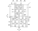
なお、図5及び図6は、n=4の場合のフィルムコンデンサ1の一例を示す。このフィルムコンデンサ1には、誘電体フィルム2を介して、第1非分割電極41と第2分割電極52とが対向する部分(Z1及びZ4部分)と、第1分割電極51と第2分割電極52とが対向する部分(Z2及びZ3部分)と、が存在する。
Note that FIGS. 5 and 6 show an example of the film capacitor 1 when n=4. The film capacitor 1 has a portion (Z1 and Z4 portions) where the first non-split electrode 41 and the second split electrode 52 face each other through the dielectric film 2, and the first split electrode 51 and the second split electrode. 52 (Z2 and Z3 portions) are present.
<誘電体フィルム>
本実施形態の誘電体フィルム2は、第1~3実施形態の誘電体フィルム2と同様である。 <Dielectric film>
Thedielectric film 2 of this embodiment is the same as the dielectric films 2 of the first to third embodiments.
本実施形態の誘電体フィルム2は、第1~3実施形態の誘電体フィルム2と同様である。 <Dielectric film>
The
<第1電極>
〔nが3以上の奇数の場合〕
第1電極31は、少なくとも1つ以上の第1マージン部211により、少なくとも1つ以上の第1非分割電極41と、少なくとも1つ以上の第1分割電極51と、に分離されている。特に第1電極31は、(n+1)/2個に分離される。具体例を挙げると、n=3の場合、第1電極31は、2つに分離される(図1参照)。例えば、第1電極31は、1つの第1マージン部211により、1つの第1非分割電極41と、1つの第1分割電極51と、に分離される。 <First electrode>
[When n is an odd number of 3 or more]
Thefirst electrode 31 is separated by at least one or more first margin portions 211 into at least one or more first non-split electrodes 41 and at least one or more first split electrodes 51 . In particular, the first electrodes 31 are separated into (n+1)/2 pieces. As a specific example, when n=3, the first electrode 31 is separated into two (see FIG. 1). For example, the first electrode 31 is separated into one first non-split electrode 41 and one first split electrode 51 by one first margin portion 211 .
〔nが3以上の奇数の場合〕
第1電極31は、少なくとも1つ以上の第1マージン部211により、少なくとも1つ以上の第1非分割電極41と、少なくとも1つ以上の第1分割電極51と、に分離されている。特に第1電極31は、(n+1)/2個に分離される。具体例を挙げると、n=3の場合、第1電極31は、2つに分離される(図1参照)。例えば、第1電極31は、1つの第1マージン部211により、1つの第1非分割電極41と、1つの第1分割電極51と、に分離される。 <First electrode>
[When n is an odd number of 3 or more]
The
さらに第1電極31は、第1端面電極310に接続されるが、第2端面電極320には接続されない。具体例を挙げると、n=3の場合、誘電体フィルム2の短手方向Sの一方側(左側)に配置された第1非分割電極41は、第1端面電極310に接続されるが、誘電体フィルム2の短手方向Sの他方側(右側)に配置された第1分割電極51は、第2端面電極320に接続されない。
Furthermore, the first electrode 31 is connected to the first edge electrode 310 but not to the second edge electrode 320 . To give a specific example, when n=3, the first undivided electrode 41 arranged on one side (left side) in the transverse direction S of the dielectric film 2 is connected to the first end surface electrode 310. The first split electrode 51 arranged on the other side (right side) of the dielectric film 2 in the transverse direction S is not connected to the second edge electrode 320 .
〔nが4以上の偶数の場合〕
第1電極31は、少なくとも1つ以上の第1マージン部211により、少なくとも1つ以上の第1非分割電極41と、少なくとも1つ以上の第1分割電極51と、に分離されている。特に第1電極31は、(n+2)/2個に分離される。具体例を挙げると、n=4の場合、第1電極31は、3つに分離される(図5及び図6参照)。例えば、第1電極31は、2つの第1マージン部211により、2つの第1非分割電極41と、1つの第1分割電極51と、に分離される。 [When n is an even number of 4 or more]
Thefirst electrode 31 is separated by at least one or more first margin portions 211 into at least one or more first non-split electrodes 41 and at least one or more first split electrodes 51 . In particular, the first electrodes 31 are separated into (n+2)/2 pieces. As a specific example, when n=4, the first electrode 31 is separated into three (see FIGS. 5 and 6). For example, the first electrode 31 is separated into two first non-split electrodes 41 and one first split electrode 51 by two first margin portions 211 .
第1電極31は、少なくとも1つ以上の第1マージン部211により、少なくとも1つ以上の第1非分割電極41と、少なくとも1つ以上の第1分割電極51と、に分離されている。特に第1電極31は、(n+2)/2個に分離される。具体例を挙げると、n=4の場合、第1電極31は、3つに分離される(図5及び図6参照)。例えば、第1電極31は、2つの第1マージン部211により、2つの第1非分割電極41と、1つの第1分割電極51と、に分離される。 [When n is an even number of 4 or more]
The
さらに第1電極31は、第1端面電極310及び第2端面電極320に接続される。具体例を挙げると、n=4の場合、誘電体フィルム2の短手方向Sの一方側(左側)に配置された第1非分割電極41は、第1端面電極310に接続されるとともに、誘電体フィルム2の短手方向Sの他方側(右側)に配置された第1非分割電極41は、第2端面電極320に接続される。
Furthermore, the first electrode 31 is connected to the first edge electrode 310 and the second edge electrode 320 . As a specific example, when n=4, the first non-divided electrode 41 arranged on one side (left side) in the transverse direction S of the dielectric film 2 is connected to the first end surface electrode 310, The first non-split electrode 41 arranged on the other side (right side) of the dielectric film 2 in the transverse direction S is connected to the second end surface electrode 320 .
〔nが3以上の整数の場合〕
第1非分割電極41は端面電極30に接続されることが好ましい。 [When n is an integer of 3 or more]
The firstnon-split electrode 41 is preferably connected to the edge electrode 30 .
第1非分割電極41は端面電極30に接続されることが好ましい。 [When n is an integer of 3 or more]
The first
<第2電極>
〔nが3以上の奇数の場合〕
第2電極32は、少なくとも1つ以上の第2マージン部212により、少なくとも1つ以上の第2分割電極52を含んだ状態で分離されている。特に第2電極32は、(n+1)/2個に分離される。具体例を挙げると、n=3の場合、第2電極32は、2つに分離される(図1参照)。例えば、第2電極32は、1つの第2マージン部212により、1つの第2分割電極52と、1つの第2非分割電極42と、に分離される。このように、第2電極32が1つのみの第2分割電極52を含む場合には、第2電極32は、少なくとも1つ以上の第2非分割電極42を更に含む。 <Second electrode>
[When n is an odd number of 3 or more]
Thesecond electrodes 32 are separated by at least one or more second margin portions 212 while including at least one or more second split electrodes 52 . In particular, the second electrodes 32 are separated into (n+1)/2 pieces. As a specific example, when n=3, the second electrode 32 is separated into two (see FIG. 1). For example, the second electrode 32 is separated into one second split electrode 52 and one second non-split electrode 42 by one second margin portion 212 . Thus, when the second electrode 32 includes only one second split electrode 52 , the second electrode 32 further includes at least one or more second non-split electrodes 42 .
〔nが3以上の奇数の場合〕
第2電極32は、少なくとも1つ以上の第2マージン部212により、少なくとも1つ以上の第2分割電極52を含んだ状態で分離されている。特に第2電極32は、(n+1)/2個に分離される。具体例を挙げると、n=3の場合、第2電極32は、2つに分離される(図1参照)。例えば、第2電極32は、1つの第2マージン部212により、1つの第2分割電極52と、1つの第2非分割電極42と、に分離される。このように、第2電極32が1つのみの第2分割電極52を含む場合には、第2電極32は、少なくとも1つ以上の第2非分割電極42を更に含む。 <Second electrode>
[When n is an odd number of 3 or more]
The
さらに第2電極32は、第1端面電極310には接続されないが、第2端面電極320には接続される。具体例を挙げると、n=3の場合、誘電体フィルム2の短手方向Sの一方側(左側)に配置された第2分割電極52は、第1端面電極310に接続されないが、誘電体フィルム2の短手方向Sの他方側(右側)に配置された第2非分割電極42は、第2端面電極320に接続される。
Furthermore, the second electrode 32 is not connected to the first edge electrode 310 but is connected to the second edge electrode 320 . As a specific example, when n=3, the second split electrode 52 arranged on one side (left side) in the transverse direction S of the dielectric film 2 is not connected to the first end surface electrode 310, but the dielectric The second non-split electrode 42 arranged on the other side (right side) of the film 2 in the transverse direction S is connected to the second edge electrode 320 .
〔nが4以上の偶数の場合〕
第2電極32は、少なくとも1つ以上の第2マージン部212により、少なくとも1つ以上の第2分割電極52を含んだ状態で分離されている。特に第2電極32は、n/2個に分離される。具体例を挙げると、n=4の場合、第2電極32は、2つに分離される(図5及び図6参照)。例えば、第2電極32は、1つの第2マージン部212により、2つの第2分割電極52に分離される。このように、第2電極32が2つ以上の第2分割電極52を含む場合、各々の第2小電極群520は、短手方向Sに並んでいる(図6参照)。一方、第2電極32が1つのみの第2分割電極52を含む場合には、第2電極32は、少なくとも1つ以上の第2非分割電極42を更に含む。 [When n is an even number of 4 or more]
Thesecond electrodes 32 are separated by at least one or more second margin portions 212 while including at least one or more second split electrodes 52 . In particular, the second electrodes 32 are separated into n/2 pieces. As a specific example, when n=4, the second electrode 32 is separated into two (see FIGS. 5 and 6). For example, the second electrode 32 is separated into two second split electrodes 52 by one second margin portion 212 . Thus, when the second electrode 32 includes two or more second split electrodes 52, each second small electrode group 520 is arranged in the lateral direction S (see FIG. 6). On the other hand, when the second electrode 32 includes only one second split electrode 52 , the second electrode 32 further includes at least one or more second non-split electrodes 42 .
第2電極32は、少なくとも1つ以上の第2マージン部212により、少なくとも1つ以上の第2分割電極52を含んだ状態で分離されている。特に第2電極32は、n/2個に分離される。具体例を挙げると、n=4の場合、第2電極32は、2つに分離される(図5及び図6参照)。例えば、第2電極32は、1つの第2マージン部212により、2つの第2分割電極52に分離される。このように、第2電極32が2つ以上の第2分割電極52を含む場合、各々の第2小電極群520は、短手方向Sに並んでいる(図6参照)。一方、第2電極32が1つのみの第2分割電極52を含む場合には、第2電極32は、少なくとも1つ以上の第2非分割電極42を更に含む。 [When n is an even number of 4 or more]
The
さらに第2電極32は、第1端面電極310及び第2端面電極320には接続されない。具体例を挙げると、n=4の場合、誘電体フィルム2の短手方向Sの一方側(左側)に配置された第2分割電極52は、第1端面電極310に接続されないとともに、誘電体フィルム2の短手方向Sの他方側(右側)に配置された第2分割電極52も、第2端面電極320に接続されない。
Furthermore, the second electrode 32 is not connected to the first edge electrode 310 and the second edge electrode 320 . As a specific example, when n=4, the second split electrode 52 arranged on one side (left side) of the dielectric film 2 in the transverse direction S is not connected to the first end face electrode 310, and the dielectric The second split electrode 52 arranged on the other side (right side) of the film 2 in the transverse direction S is also not connected to the second edge electrode 320 .
〔nが3以上の整数の場合〕
第2電極32が第2非分割電極42を含む場合には、第2非分割電極42は端面電極30に接続されることが好ましい。 [When n is an integer of 3 or more]
If thesecond electrode 32 includes a second unsplit electrode 42 , the second unsplit electrode 42 is preferably connected to the edge electrode 30 .
第2電極32が第2非分割電極42を含む場合には、第2非分割電極42は端面電極30に接続されることが好ましい。 [When n is an integer of 3 or more]
If the
<作用効果>
本実施形態によれば、フィルムコンデンサ1を高電圧で使用しても、全体としての機能を保持することができる。 <Effect>
According to this embodiment, even if thefilm capacitor 1 is used at a high voltage, the function as a whole can be maintained.
本実施形態によれば、フィルムコンデンサ1を高電圧で使用しても、全体としての機能を保持することができる。 <Effect>
According to this embodiment, even if the
すなわち、本実施形態に係るフィルムコンデンサ1は、誘電体フィルム2の短手方向Sに直列に接続された3つ以上の単位コンデンサ10を含む(図5及び図9A参照)。そのため、図7A及び図8Aに示すフィルムコンデンサ1の第1端面電極310及び第2端面電極320間に印加される電圧と、本実施形態に係るフィルムコンデンサ1の第1端面電極310及び第2端面電極320間に印加される電圧とが同じである場合、図7A及び図8Aに示すフィルムコンデンサ1の単位コンデンサ10に印加される電圧よりも、本実施形態に係るフィルムコンデンサ1の単位コンデンサ10に印加される電圧の方が小さくなることにより、誘電体フィルム2の損傷を更に抑制しやすくなる。
That is, the film capacitor 1 according to this embodiment includes three or more unit capacitors 10 connected in series in the transverse direction S of the dielectric film 2 (see FIGS. 5 and 9A). Therefore, the voltage applied between the first end surface electrode 310 and the second end surface electrode 320 of the film capacitor 1 shown in FIGS. 7A and 8A and the first end surface electrode 310 and the second end surface of the film capacitor 1 according to the present embodiment When the voltage applied between the electrodes 320 is the same, the voltage applied to the unit capacitor 10 of the film capacitor 1 according to the present embodiment is higher than the voltage applied to the unit capacitor 10 of the film capacitor 1 shown in FIGS. 7A and 8A. By reducing the applied voltage, it becomes easier to suppress damage to the dielectric film 2 .
さらに本実施形態に係るフィルムコンデンサ1では、複数の第1小電極511は、第1ヒューズ61で接続されているとともに、複数の第2小電極521は、第2ヒューズ62で接続されている(図1及び図6参照)。そのため、第1電極31及び第2電極32間の一部が短絡しても、第1ヒューズ61及び第2ヒューズ62の少なくともいずれかが切断される。
Furthermore, in the film capacitor 1 according to this embodiment, the plurality of first small electrodes 511 are connected by the first fuse 61, and the plurality of second small electrodes 521 are connected by the second fuse 62 ( 1 and 6). Therefore, even if a part between the first electrode 31 and the second electrode 32 is short-circuited, at least one of the first fuse 61 and the second fuse 62 is disconnected.
したがって、本実施形態によれば、フィルムコンデンサ1を高電圧で使用しても、全体としての機能を保持することができる。
Therefore, according to this embodiment, even if the film capacitor 1 is used at a high voltage, the function as a whole can be maintained.
1 フィルムコンデンサ
10 単位コンデンサ
2 誘電体フィルム
201 第1面
202 第2面
211 第1マージン部
212 第2マージン部
221 第1短手方向スリット部
222 第2短手方向スリット部
31 第1電極
32 第2電極
41 第1非分割電極
42 第2非分割電極
51 第1分割電極
510 第1小電極群
511 第1小電極
52 第2分割電極
520 第2小電極群
521 第2小電極
61 第1ヒューズ
62 第2ヒューズ
S 短手方向
L 長手方向
Wa1 幅
Wb1 幅
Wa2 幅
Wb2 幅 1film capacitor 10 unit capacitor 2 dielectric film 201 first surface 202 second surface 211 first margin part 212 second margin part 221 first transverse direction slit part 222 second transverse direction slit part 31 first electrode 32 second 2 electrodes 41 first unsplit electrode 42 second unsplit electrode 51 first split electrode 510 first small electrode group 511 first small electrode 52 second split electrode 520 second small electrode group 521 second small electrode 61 first fuse 62 Second fuse S Transverse direction L Longitudinal direction Wa1 width Wb1 width Wa2 width Wb2 width
10 単位コンデンサ
2 誘電体フィルム
201 第1面
202 第2面
211 第1マージン部
212 第2マージン部
221 第1短手方向スリット部
222 第2短手方向スリット部
31 第1電極
32 第2電極
41 第1非分割電極
42 第2非分割電極
51 第1分割電極
510 第1小電極群
511 第1小電極
52 第2分割電極
520 第2小電極群
521 第2小電極
61 第1ヒューズ
62 第2ヒューズ
S 短手方向
L 長手方向
Wa1 幅
Wb1 幅
Wa2 幅
Wb2 幅 1
Claims (8)
- 第1面と前記第1面の反対側の第2面とを有し、短手方向に対して直交する長手方向に延びる誘電体フィルムと、
前記第1面に配置された第1電極と、
前記第2面に配置された第2電極と、を備え、
前記誘電体フィルムを介して前記第1電極と前記第2電極とが対向することで、前記短手方向に直列に接続された3つの単位コンデンサを含み、
前記第1電極は、前記長手方向に延びる第1マージン部により、前記長手方向に延びる第1非分割電極と、第1分割電極と、に分離され、
前記第1分割電極は、前記短手方向に延びる第1短手方向スリット部により、前記長手方向に並ぶ複数の第1小電極群に分割され、
前記複数の第1小電極群の各々は、第1ヒューズで接続された複数の第1小電極を含み、
前記第2電極は、前記長手方向に延びる第2マージン部により、前記長手方向に延びる第2非分割電極と、第2分割電極と、に分離され、
前記第2分割電極は、前記短手方向に延びる第2短手方向スリット部により、前記長手方向に並ぶ複数の第2小電極群に分割され、
前記複数の第2小電極群の各々は、第2ヒューズで接続された複数の第2小電極を含む、
フィルムコンデンサ。 a dielectric film having a first surface and a second surface opposite to the first surface and extending in a longitudinal direction perpendicular to the transverse direction;
a first electrode disposed on the first surface;
a second electrode disposed on the second surface;
three unit capacitors connected in series in the lateral direction by facing the first electrode and the second electrode via the dielectric film;
the first electrode is separated into a first non-split electrode extending in the longitudinal direction and a first split electrode by the first margin portion extending in the longitudinal direction;
The first divided electrodes are divided into a plurality of first small electrode groups aligned in the longitudinal direction by first transverse direction slit portions extending in the transverse direction,
each of the plurality of first small electrode groups includes a plurality of first small electrodes connected by a first fuse;
the second electrode is separated into a second non-split electrode extending in the longitudinal direction and a second split electrode by the second margin portion extending in the longitudinal direction;
The second divided electrodes are divided into a plurality of second small electrode groups aligned in the longitudinal direction by second transverse direction slit portions extending in the transverse direction,
each of the plurality of second small electrode groups includes a plurality of second small electrodes connected by a second fuse;
Film capacitor. - 前記誘電体フィルムを介して、前記第1非分割電極と前記第2分割電極とが対向する部分と、前記第1分割電極と前記第2分割電極とが対向する部分と、前記第1分割電極と前記第2非分割電極とが対向する部分と、が存在し、
前記第1分割電極と前記第2分割電極とが対向する部分における前記第1短手方向スリット部の幅が、前記第1分割電極と前記第2非分割電極とが対向する部分における前記第1短手方向スリット部の幅よりも小さい、
請求項1に記載のフィルムコンデンサ。 A portion where the first non-split electrode and the second split electrode face each other, a portion where the first split electrode and the second split electrode face each other, and the first split electrode, with the dielectric film interposed therebetween. and a portion where the second undivided electrode faces,
The width of the first transverse direction slit portion at the portion where the first split electrode and the second split electrode face each other is the first width at the portion where the first split electrode and the second non-split electrode face each other. smaller than the width of the slit in the transverse direction,
The film capacitor according to claim 1. - 前記第1分割電極と前記第2分割電極とが対向する部分における前記第2短手方向スリット部の幅が、前記第1非分割電極と前記第2分割電極とが対向する部分における前記第2短手方向スリット部の幅よりも小さい、
請求項2に記載のフィルムコンデンサ。 The width of the second transverse direction slit portion at the portion where the first split electrode and the second split electrode face each other is the second width at the portion where the first non-split electrode and the second split electrode face each other. smaller than the width of the slit in the transverse direction,
3. A film capacitor according to claim 2. - 前記誘電体フィルムを介して、前記第1非分割電極と前記第2分割電極とが対向する部分と、前記第1分割電極と前記第2分割電極とが対向する部分と、前記第1分割電極と前記第2非分割電極とが対向する部分と、が存在し、
前記第1分割電極と前記第2分割電極とが対向する部分における前記第1短手方向スリット部の幅及び前記第2短手方向スリット部の幅の和が、前記第1分割電極と前記第2非分割電極とが対向する部分における前記第1短手方向スリット部の幅、及び前記第1非分割電極と前記第2分割電極とが対向する部分における前記第2短手方向スリット部の幅の少なくともいずれかに等しい、
請求項1~3のいずれか1項に記載のフィルムコンデンサ。 A portion where the first non-split electrode and the second split electrode face each other, a portion where the first split electrode and the second split electrode face each other, and the first split electrode, with the dielectric film interposed therebetween. and a portion where the second undivided electrode faces,
The sum of the width of the first width direction slit portion and the width of the second width direction slit portion in the portion where the first division electrode and the second division electrode face each other is the sum of the width of the first division electrode and the width of the second division electrode. Width of the first transverse direction slit portion at the portion where the two undivided electrodes face each other, and width of the second transverse direction slit portion at the portion where the first undivided electrode and the second divided electrode face each other. equal to at least one of
A film capacitor according to any one of claims 1 to 3. - 前記誘電体フィルムを介して、前記第1非分割電極と前記第2分割電極とが対向する部分と、前記第1分割電極と前記第2分割電極とが対向する部分と、前記第1分割電極と前記第2非分割電極とが対向する部分と、が存在し、
前記第1分割電極と前記第2分割電極とが対向する部分における前記第1短手方向スリット部の数が、前記第1分割電極と前記第2非分割電極とが対向する部分における前記第1短手方向スリット部の数よりも少ない、
請求項1~4のいずれか1項に記載のフィルムコンデンサ。 A portion where the first non-split electrode and the second split electrode face each other, a portion where the first split electrode and the second split electrode face each other, and the first split electrode, with the dielectric film interposed therebetween. and a portion where the second undivided electrode faces,
The number of the first transverse direction slit portions in the portion where the first split electrode and the second split electrode face each other is the first number in the portion where the first split electrode and the second non-split electrode face each other. less than the number of slits in the transverse direction,
A film capacitor according to any one of claims 1 to 4. - 前記第1分割電極と前記第2分割電極とが対向する部分における前記第2短手方向スリット部の数が、前記第1非分割電極と前記第2分割電極とが対向する部分における前記第2短手方向スリット部の数よりも少ない、
請求項5に記載のフィルムコンデンサ。 The number of the second transverse direction slit portions in the portion where the first split electrode and the second split electrode face each other is the second number in the portion where the first non-split electrode and the second split electrode face each other. less than the number of slits in the transverse direction,
The film capacitor according to claim 5. - 第1面と前記第1面の反対側の第2面とを有し、短手方向に対して直交する長手方向に延びる誘電体フィルムと、
前記第1面に配置された第1電極と、
前記第2面に配置された第2電極と、を備え、
前記誘電体フィルムを介して前記第1電極と前記第2電極とが対向することで、前記短手方向に直列に接続された3つ以上の奇数個の単位コンデンサを含み、
前記第1電極は、前記長手方向に延びる少なくとも1つ以上の第1マージン部により、前記長手方向に延びる少なくとも1つ以上の第1非分割電極と、少なくとも1つ以上の第1分割電極と、に分離され、
前記第1分割電極は、前記短手方向に延びる第1短手方向スリット部により、前記長手方向に並ぶ複数の第1小電極群に分割され、
前記複数の第1小電極群の各々は、第1ヒューズで接続された複数の第1小電極を含み、
前記第2電極は、前記長手方向に延びる少なくとも1つ以上の第2マージン部により、少なくとも1つ以上の第2分割電極を含んだ状態で分離され、
前記第2分割電極は、前記短手方向に延びる第2短手方向スリット部により、前記長手方向に並ぶ複数の第2小電極群に分割され、
前記複数の第2小電極群の各々は、第2ヒューズで接続された複数の第2小電極を含む、
フィルムコンデンサ。 a dielectric film having a first surface and a second surface opposite to the first surface and extending in a longitudinal direction perpendicular to the transverse direction;
a first electrode disposed on the first surface;
a second electrode disposed on the second surface;
including three or more odd-numbered unit capacitors connected in series in the lateral direction by the first electrode and the second electrode facing each other through the dielectric film;
At least one or more first undivided electrodes extending in the longitudinal direction and at least one or more first segmented electrodes are formed by at least one or more first margin portions extending in the longitudinal direction. separated into
The first divided electrodes are divided into a plurality of first small electrode groups aligned in the longitudinal direction by first transverse direction slit portions extending in the transverse direction,
each of the plurality of first small electrode groups includes a plurality of first small electrodes connected by a first fuse;
the second electrode is separated by at least one or more second margin portions extending in the longitudinal direction while including at least one or more second split electrodes;
The second divided electrodes are divided into a plurality of second small electrode groups aligned in the longitudinal direction by second transverse direction slit portions extending in the transverse direction,
each of the plurality of second small electrode groups includes a plurality of second small electrodes connected by a second fuse;
Film capacitor. - 第1面と前記第1面の反対側の第2面とを有し、短手方向に対して直交する長手方向に延びる誘電体フィルムと、
前記第1面に配置された第1電極と、
前記第2面に配置された第2電極と、を備え、
前記誘電体フィルムを介して前記第1電極と前記第2電極とが対向することで、前記短手方向に直列に接続された4つ以上の偶数個の単位コンデンサを含み、
前記第1電極は、前記長手方向に延びる少なくとも1つ以上の第1マージン部により、前記長手方向に延びる少なくとも1つ以上の第1非分割電極と、少なくとも1つ以上の第1分割電極と、に分離され、
前記第1分割電極は、前記短手方向に延びる第1短手方向スリット部により、前記長手方向に並ぶ複数の第1小電極群に分割され、
前記複数の第1小電極群の各々は、第1ヒューズで接続された複数の第1小電極を含み、
前記第2電極は、前記長手方向に延びる少なくとも1つ以上の第2マージン部により、少なくとも1つ以上の第2分割電極を含んだ状態で分離され、
前記第2分割電極は、前記短手方向に延びる第2短手方向スリット部により、前記長手方向に並ぶ複数の第2小電極群に分割され、
前記複数の第2小電極群の各々は、第2ヒューズで接続された複数の第2小電極を含む、
フィルムコンデンサ。 a dielectric film having a first surface and a second surface opposite to the first surface and extending in a longitudinal direction perpendicular to the transverse direction;
a first electrode disposed on the first surface;
a second electrode disposed on the second surface;
including four or more even number of unit capacitors connected in series in the transverse direction by the first electrode and the second electrode facing each other through the dielectric film;
At least one or more first undivided electrodes extending in the longitudinal direction and at least one or more first segmented electrodes are formed by at least one or more first margin portions extending in the longitudinal direction. separated into
The first divided electrodes are divided into a plurality of first small electrode groups aligned in the longitudinal direction by first transverse direction slit portions extending in the transverse direction,
each of the plurality of first small electrode groups includes a plurality of first small electrodes connected by a first fuse;
the second electrode is separated by at least one or more second margin portions extending in the longitudinal direction while including at least one or more second split electrodes;
The second divided electrodes are divided into a plurality of second small electrode groups aligned in the longitudinal direction by second transverse direction slit portions extending in the transverse direction,
each of the plurality of second small electrode groups includes a plurality of second small electrodes connected by a second fuse;
Film capacitor.
Priority Applications (2)
| Application Number | Priority Date | Filing Date | Title |
|---|---|---|---|
| JP2023527621A JPWO2022259899A1 (en) | 2021-06-11 | 2022-05-30 | |
| CN202280040136.8A CN117461104A (en) | 2021-06-11 | 2022-05-30 | Thin film capacitor |
Applications Claiming Priority (2)
| Application Number | Priority Date | Filing Date | Title |
|---|---|---|---|
| JP2021-098311 | 2021-06-11 | ||
| JP2021098311 | 2021-06-11 |
Publications (1)
| Publication Number | Publication Date |
|---|---|
| WO2022259899A1 true WO2022259899A1 (en) | 2022-12-15 |
Family
ID=84424912
Family Applications (1)
| Application Number | Title | Priority Date | Filing Date |
|---|---|---|---|
| PCT/JP2022/022000 WO2022259899A1 (en) | 2021-06-11 | 2022-05-30 | Film capacitor |
Country Status (3)
| Country | Link |
|---|---|
| JP (1) | JPWO2022259899A1 (en) |
| CN (1) | CN117461104A (en) |
| WO (1) | WO2022259899A1 (en) |
Citations (4)
| Publication number | Priority date | Publication date | Assignee | Title |
|---|---|---|---|---|
| JPH0272609A (en) * | 1988-09-07 | 1990-03-12 | Marcon Electron Co Ltd | Sh capacitor |
| JPH04250608A (en) * | 1991-01-25 | 1992-09-07 | Nichicon Corp | Energy storage quick discharge capacitor |
| JPH06168844A (en) * | 1992-04-06 | 1994-06-14 | Nichicon Corp | High-pressure capacitor for power |
| JPH07240336A (en) * | 1994-08-29 | 1995-09-12 | Nichicon Corp | High-voltage power capacitor |
-
2022
- 2022-05-30 JP JP2023527621A patent/JPWO2022259899A1/ja active Pending
- 2022-05-30 WO PCT/JP2022/022000 patent/WO2022259899A1/en active Application Filing
- 2022-05-30 CN CN202280040136.8A patent/CN117461104A/en active Pending
Patent Citations (4)
| Publication number | Priority date | Publication date | Assignee | Title |
|---|---|---|---|---|
| JPH0272609A (en) * | 1988-09-07 | 1990-03-12 | Marcon Electron Co Ltd | Sh capacitor |
| JPH04250608A (en) * | 1991-01-25 | 1992-09-07 | Nichicon Corp | Energy storage quick discharge capacitor |
| JPH06168844A (en) * | 1992-04-06 | 1994-06-14 | Nichicon Corp | High-pressure capacitor for power |
| JPH07240336A (en) * | 1994-08-29 | 1995-09-12 | Nichicon Corp | High-voltage power capacitor |
Also Published As
| Publication number | Publication date |
|---|---|
| JPWO2022259899A1 (en) | 2022-12-15 |
| CN117461104A (en) | 2024-01-26 |
Similar Documents
| Publication | Publication Date | Title |
|---|---|---|
| JP5012524B2 (en) | Metallized film capacitors | |
| EP0866479A2 (en) | Laminated capacitor | |
| US4556929A (en) | Multi-layer ceramic capacitor | |
| JP2007299921A (en) | Film capacitor | |
| JP5025924B2 (en) | Metallized film capacitors | |
| US20110013341A1 (en) | Multilayer chip capacitor | |
| WO2022259899A1 (en) | Film capacitor | |
| US20100079925A1 (en) | Multilayer capacitor | |
| JP2007053222A (en) | Metallized film capacitor | |
| JP2010016047A (en) | Metallized film capacitor | |
| JP5228591B2 (en) | Metallized film capacitors | |
| JP2009267217A (en) | Metallized film capacitor | |
| JP5294123B2 (en) | Metallized film capacitors | |
| WO2022259900A1 (en) | Film capacitor | |
| JP6330139B2 (en) | Metallized film capacitors | |
| JP6614558B2 (en) | Metallized film and metallized film capacitor | |
| US8116064B2 (en) | Multilayer capacitor | |
| JP7296734B2 (en) | Metallized film and metallized film capacitors | |
| JP2006100507A (en) | Capacitor connecting structure | |
| JP2008235414A (en) | Metalized film capacitor | |
| JP2017143170A (en) | Metalized film and metalized film capacitor using the same | |
| JP2008235415A (en) | Metalized film capacitor | |
| JP2008103451A (en) | Metallized film capacitor | |
| JP2012099747A (en) | Metal deposition film | |
| US5157583A (en) | Series wound capacitive structure |
Legal Events
| Date | Code | Title | Description |
|---|---|---|---|
| 121 | Ep: the epo has been informed by wipo that ep was designated in this application |
Ref document number: 22820081 Country of ref document: EP Kind code of ref document: A1 |
|
| WWE | Wipo information: entry into national phase |
Ref document number: 2023527621 Country of ref document: JP |
|
| NENP | Non-entry into the national phase |
Ref country code: DE |