WO2022259756A1 - 光学系、及び、画像表示装置 - Google Patents
光学系、及び、画像表示装置 Download PDFInfo
- Publication number
- WO2022259756A1 WO2022259756A1 PCT/JP2022/017533 JP2022017533W WO2022259756A1 WO 2022259756 A1 WO2022259756 A1 WO 2022259756A1 JP 2022017533 W JP2022017533 W JP 2022017533W WO 2022259756 A1 WO2022259756 A1 WO 2022259756A1
- Authority
- WO
- WIPO (PCT)
- Prior art keywords
- directions
- optical system
- branch
- region
- periodic structure
- Prior art date
- Legal status (The legal status is an assumption and is not a legal conclusion. Google has not performed a legal analysis and makes no representation as to the accuracy of the status listed.)
- Ceased
Links
Images







Classifications
-
- G—PHYSICS
- G02—OPTICS
- G02B—OPTICAL ELEMENTS, SYSTEMS OR APPARATUS
- G02B27/00—Optical systems or apparatus not provided for by any of the groups G02B1/00 - G02B26/00, G02B30/00
- G02B27/0081—Optical systems or apparatus not provided for by any of the groups G02B1/00 - G02B26/00, G02B30/00 with means for altering, e.g. enlarging, the entrance or exit pupil
-
- G—PHYSICS
- G02—OPTICS
- G02B—OPTICAL ELEMENTS, SYSTEMS OR APPARATUS
- G02B27/00—Optical systems or apparatus not provided for by any of the groups G02B1/00 - G02B26/00, G02B30/00
- G02B27/01—Head-up displays
- G02B27/017—Head mounted
- G02B27/0172—Head mounted characterised by optical features
-
- G—PHYSICS
- G02—OPTICS
- G02B—OPTICAL ELEMENTS, SYSTEMS OR APPARATUS
- G02B5/00—Optical elements other than lenses
- G02B5/18—Diffraction gratings
- G02B5/1809—Diffraction gratings with pitch less than or comparable to the wavelength
-
- G—PHYSICS
- G02—OPTICS
- G02B—OPTICAL ELEMENTS, SYSTEMS OR APPARATUS
- G02B5/00—Optical elements other than lenses
- G02B5/18—Diffraction gratings
- G02B5/1866—Transmission gratings characterised by their structure, e.g. step profile, contours of substrate or grooves, pitch variations, materials
-
- G—PHYSICS
- G02—OPTICS
- G02B—OPTICAL ELEMENTS, SYSTEMS OR APPARATUS
- G02B6/00—Light guides; Structural details of arrangements comprising light guides and other optical elements, e.g. couplings
- G02B6/24—Coupling light guides
- G02B6/26—Optical coupling means
- G02B6/34—Optical coupling means utilising prism or grating
-
- G—PHYSICS
- G02—OPTICS
- G02B—OPTICAL ELEMENTS, SYSTEMS OR APPARATUS
- G02B27/00—Optical systems or apparatus not provided for by any of the groups G02B1/00 - G02B26/00, G02B30/00
- G02B27/01—Head-up displays
- G02B27/017—Head mounted
- G02B27/0172—Head mounted characterised by optical features
- G02B2027/0174—Head mounted characterised by optical features holographic
Definitions
- the present disclosure relates to optical systems and image display devices.
- Patent Document 1 discloses an optical element (optical system) including a waveguide (light guide member) for expanding an exit pupil in two directions.
- the optical elements comprise three diffractive optical elements (DOEs).
- a first DOE couples light from the display element into the waveguide.
- a second DOE expands the exit pupil in a first direction along a first coordinate axis.
- a third DOE expands the exit pupil in a second direction along a second coordinate axis to cause the light to exit the waveguide.
- Patent document 2 discloses a waveguide having an incident diffractive optical element (in-coupling diffractive optic) and an output diffractive optical element (out-coupling diffractive optic) on its surface.
- the output diffractive optical element has a plurality of grating vectors that are not parallel to the grating vectors of the input diffractive optical element by comprising a diffractive array with alternating columns of different grating vectors.
- Patent Documents 1 and 2 are used, for example, in head-mounted displays. In head-mounted displays, it is sometimes desired to reduce the size of waveguides of optical elements, depending on how the optical elements are used.
- the present disclosure provides an optical system and an image display device in which the size of the light guide member can be reduced.
- An optical system includes a light guide member that guides image light forming an image output from a display element to a user's visual field area as a virtual image.
- the light guide member has a plate-like main body and a periodic structure formed in the main body.
- the periodic structure has periodicity in three predetermined directions intersecting each other within a predetermined plane perpendicular to the thickness direction of the main body.
- the periodic structure branches the image light incident from the display element into a plurality of branch directions including first, second, and third branch directions parallel to the three predetermined directions, and propagates through the main body. and an emission area for emitting the image light propagating in the plurality of branching directions in the body from the body to the viewing area.
- An image display device includes the optical system described above and the display element.
- Schematic diagram of a configuration example of an image display device including an optical system Schematic plan view of a configuration example of a light guide member of the optical system of FIG. Schematic side view of a configuration example of a light guide member of the optical system of FIG. A plan view of a configuration example of the periodic structure of the light guide member of FIG. A perspective view of a configuration example of the periodic structure of the light guide member of FIG.
- Explanatory drawing of an example of the wave vector of the periodic structure of the light guide member of FIG. Explanatory drawing of an example of the wave vector of the periodic structure of the light guide member of FIG.
- Explanatory drawing of an example of the wave vector of the periodic structure of the light guide member of FIG. Explanatory drawing of an example of the wave vector of the periodic structure of the light guide member of FIG.
- FIG. 3 is a diagram showing simulation results of light intensity of the light guide member in FIG. 2 ;
- FIG. 10 is a plan view of a configuration example of the light guide member of Modification 1; Explanatory drawing of the emission part of the periodic structure of the light guide member of Modification 1 Explanatory drawing of the light guide member of modification 2 Explanatory drawing of the light guide member of modification 3 Explanatory diagram of a configuration example of the optical system of Modification 4 Explanatory drawing of another configuration example of the optical system of Modification 4 Explanatory drawing of an example of the wave vector of the periodic structure of the light guide member of the optical system of FIG. Explanatory drawing of another configuration example of the periodic structure of modification 4 Explanatory drawing of an example of the wave vector of the periodic structure of FIG.
- FIG. 1 is a schematic diagram of a configuration example of an image display device 1 according to one embodiment.
- the image display device 1 is, for example, a head-mounted display (HMD) that is worn on the user's head and displays an image (video).
- HMD head-mounted display
- expressions such as "directed in the direction of XX” and “propagated in the direction of XX” with respect to light mean that the light forming the image as a whole is directed in the direction of XX, and forms the image.
- a ray included in the light may be tilted with respect to the ⁇ direction.
- “light directed in the direction of XX” only requires that the principal ray of this light is directed in the direction of XX, and the secondary ray of light may be inclined with respect to the direction of XX.
- the image display device 1 includes a display element 2 and an optical system 3.
- the display element 2 outputs image light L1 that forms an image.
- the optical system 3 includes a light guide member 4 and a projection optical system 5 .
- the light guide member 4 guides the image light L1 output from the display element 2 to the user's visual field area 6 as a virtual image.
- the light guide member 4 has a plate-like body portion 40 and a periodic structure 41 formed in the body portion 40 .
- FIG. 1 depicts the image light L1 as light having directivity.
- FIG. 2 is a schematic plan view of a configuration example of the light guide member 4
- FIG. 3 is a schematic side view of a configuration example of the light guide member 4.
- FIG. 3 a pupil L10 is shown instead of the display element 2 and the projection optical system 5 in order to clearly show the pupil dilation function of the image display device 1. As shown in FIG.
- the periodic structure 41 of the light guide member 4 has periodicity in three predetermined directions A1, A2, and A3 that intersect each other within a predetermined plane perpendicular to the thickness direction of the main body 40.
- Periodic structure 41 includes a coupling region 42 and an emission region 43 .
- the coupling region 42 splits the image light L1 into a plurality of branch directions including first, second and third branch directions D1, D2 and D3 parallel to three predetermined directions A1, A2 and A3, respectively. It branches to D1 to D4 and propagates inside the main body 40 .
- the emission region 43 includes image lights L2-1 to L2-4 (hereinafter collectively denoted by L2) propagating in a plurality of branch directions D1 to D4 within the main body 40. is emitted from the main body 40 to the viewing area 6 .
- the coupling region 42 has a plurality of split directions including the first, second and third branch directions D1, D2 and D3 parallel to the three predetermined directions A1, A2 and A3, respectively.
- the image light beams L2-1 to L2-4 propagated in the body portion 40 in the branch directions D1 to D4 and propagated in the main body portion 40, and the output region 43 allows the image light beams L2-1 to L2-4, which propagate in the plurality of branch directions in the body portion 40, to be viewed from the body portion 40. It is emitted to area 6.
- the light guide member 4 branches the image light L1 in a plurality of branch directions D1 to D4, splits the image light L1 into a plurality of parallel image lights L3, and emits the image light L1 to the visual field region 6.
- the periodic structure 41 acts as the coupling region 42 and the emission region 43 , and the pupil can be expanded only by the periodic structure 41 . Therefore, there is no need to provide two or three diffractive optical elements as in Patent Documents 1 and 2. As a result, the size of the light guide member 4 can be reduced.
- the image display device 1 of the present embodiment will be described in more detail below with reference to FIGS. 1 to 9.
- FIG. 1 the image display device 1 includes a display element 2 and an optical system 3 .
- the display element 2 outputs image light L1 forming an image in order to display an image (video).
- the image light L1 includes light rays output from each point of the display element 2 .
- Each point of the display element 2 corresponds to each pixel of the display element 2, for example.
- the optical axis of the display element 2 is the optical axis of the image light L1.
- the optical axis of the image light L1 is the optical axis of the light output from the center of the display element 2, for example.
- Examples of the display element 2 include known displays such as liquid crystal displays, organic EL displays, and scanning MEMS mirrors.
- the optical system 3 guides the image light L1 output by the display element 2 to the viewing area 6 set for the user's eyes.
- the user can visually recognize the image formed by the display element 2 without interruption.
- the optical system 3 expands the viewing area 6 by pupil dilation.
- the optical system 3 includes a light guide member 4 and a projection optical system 5.
- the light guide member 4 guides the image light L1 that forms the image output from the display element 2 to the user's visual field area 6 as a virtual image.
- the light guide member 4 has a plate-like body portion 40 and a periodic structure 41 .
- the main body part 40 is made of a material that is transparent in the visible light region, and has a first surface 40a and a second surface 40b in the thickness direction.
- the body portion 40 has a rectangular plate shape. As shown in FIG. 1, the body portion 40 is arranged with the first surface 40a facing the display element 2 side and the second surface 40b facing the viewing area 6 side.
- the periodic structure 41 is formed on the first surface 40 a of the body portion 40 .
- the periodic structure 41 is, for example, a rectangular region formed on the first surface 40a of the main body 40.
- the periodic structure 41 has periodicity in three predetermined directions A1, A2, and A3 that intersect each other within a predetermined plane orthogonal to the thickness direction of the main body 40.
- the three predetermined directions A1, A2, A3 are not orthogonal to each other.
- the periods of the periodic structures 41 are constant and equal in each of the three predetermined directions A1, A2, and A3.
- the predetermined direction A1 corresponds to the length direction of the body portion 40 .
- the predetermined direction A2 is the predetermined direction It intersects with A1 at a predetermined angle (eg, 60 degrees), and the predetermined direction A3 intersects with the predetermined direction A1 at a predetermined angle (eg, 120 degrees).
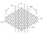
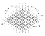
- FIG. 4 is a plan view of a configuration example of the periodic structure 41
- FIG. 5 is a perspective view of a configuration example of the periodic structure 41.
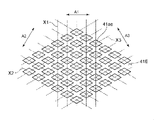
- FIG. The periodic structure 41 includes a diffraction grating composed of uneven portions 41a in the thickness direction of the body portion 40 arranged so as to have periodicity in three predetermined directions A1, A2, and A3 within a predetermined plane. More specifically, as shown in FIG. 4, in the periodic structure 41, the uneven portions 41a are arranged so as to satisfy the following conditions (1) to (3).
- the condition (1) is that "in the predetermined direction A1, rows of the uneven portions 41a are arranged at regular intervals in the direction X1 orthogonal to the predetermined direction A1".
- the periodic structure 41 acts as a diffraction grating that diffracts light in the predetermined direction A1.
- the condition (2) is that "in the predetermined direction A2, rows of the uneven portions 41a are arranged at regular intervals in the direction X2 orthogonal to the predetermined direction A2".
- the periodic structure 41 acts as a diffraction grating that diffracts light in the predetermined direction A2.
- the condition (3) is that "in the predetermined direction A3, rows of the uneven portions 41a are arranged at regular intervals in the direction X3 orthogonal to the predetermined direction A3".
- the periodic structure 41 acts as a diffraction grating that diffracts light in the predetermined direction A3.
- the uneven portions 41a are arranged in a hexagonal lattice, thereby satisfying the conditions (1) to (3).
- the uneven portion 41a is a regular hexagonal projection in plan view.
- the periodic structure 41 includes a coupling region 42 and an emission region 43. As shown in FIGS. In particular, the periodic structure 41 is formed so that there is no region separating the coupling region 42 and the emission region 43 between the coupling region 42 and the emission region 43 .
- the region that separates the coupling region 42 and the emission region 43 is, for example, a region in which the concave-convex portion 41a does not exist or a concave-convex structure different from the concave-convex portion 41a exists.
- the periodic structure 41 is formed such that the coupling region 42 and the emission region 43 are smoothly continuous without discontinuity. Therefore, the configuration of the periodic structure 41 can be simplified.
- the coupling region 42 is a region of the periodic structure 41 on which the image light L1 from the display element 2 is incident. That is, among the irregularities 41a arranged with periodicity in the three prescribed directions A1, A2, and A3 within the prescribed plane, the group of the irregularities 41a located in the region where the image light L1 from the display element 2 is incident. defines the coupling region 42 .
- the coupling region 42 is used for coupling (coupling) the display element 2 and the light guide member 4 .
- the coupling region 42 allows external light (image light L1) to enter the light guide member 4 so as to propagate through the main body 40 of the light guide member 4 under the condition of total reflection (see FIG. 3).
- the term “coupling” as used herein refers to a state in which the light propagates through the body portion 40 of the light guide member 4 under the condition of total reflection.
- the coupling region 42 is a partial region of the periodic structure 41, it has periodicity in three predetermined directions A1, A2, and A3. As a result, the coupling region 42 branches the image light L1 incident from the display element 2 into a plurality of branching directions and propagates the inside of the main body 40 .
- the coupling region 42 is located in the center of the periodic structure 41 in the length direction at one end of the periodic structure 41 in the width direction. Therefore, the plurality of branch directions includes first, second and third branch directions D1, D2 and D3 parallel to the three predetermined directions A1, A2 and A3, respectively.
- the angle between the first branch direction D1 and the third branch direction D3 is greater than the angle between the first branch direction D1 and the second branch direction D2.
- the multiple branch directions further include a fourth branch direction D4.
- the fourth branch direction D4 is opposite to the first branch direction D1.
- the angle between the first branch direction D1 and the fourth branch direction D4 is greater than the angle between the first branch direction D1 and the third branch direction D3.
- the angle between the first branch direction D1 and the second branch direction D2 is 60 degrees
- the angle between the first branch direction D1 and the third branch direction D3 is 120 degrees
- the first branch direction D1 and the fourth branch direction D4 is 180 degrees.
- the angle here the counterclockwise direction when the light guide member 4 is viewed from the direction in which the image light L1 is incident on the light guide member 4 is the positive direction.
- the coupling region 42 causes the image light L1 to enter the main body portion 40 of the light guide member 4 under the condition of total reflection with respect to the first surface 40a and the second surface 40b by diffraction. Also, the coupling region 42 is aligned with the emission region 43 in each of the three predetermined directions A1, A2, A3. As a result, the image light L2 from the coupling region 42 is incident on the emission region 43 without leakage, so that the efficiency of light transmission from the coupling region 42 to the emission region 43 is improved.
- the image light L1 is totally reflected by the first surface 40a and the second surface 40b in the main body 40 of the light guide member 4 by the coupling region 42, and travels in a plurality of branch directions D1 to D4.
- the coupling region 42 branches the image light L1 into the image light L2-1 to L2-4 propagating in the plurality of branch directions D1 to D4 inside the main body 40.
- FIG. 2 the coupling region 42 splits the image light L1 into the image lights L2-1 to L2-4 propagating through the main body 40 in a plurality of split directions D1 to D4.
- the emission area 43 is an area from which the image light L3 is emitted to the visual field area 6 in the periodic structure 41 .
- the emission region 43 is a region other than the coupling region 42 in the periodic structure 41 .
- the group of irregularities 41a not included in the coupling region 42 is An exit area 43 is defined.
- the emission area 43 emits the image light beams L2-1 to L2-4 propagating in the plurality of branch directions D1 to D4 inside the body section 40 from the body section 40 to the visual field area 6.
- FIG. 2 shows, as an example, how the image light L2-1 traveling in the first branching direction D1 from the coupling region 42 is branched into a plurality of image light L2-2 traveling in the second branching direction D2.
- FIG. 2 shows, as an example, a plurality of image lights L2-1 and L2-3 traveling in the first and third branch directions D1 and D3 from the image light L2-2 traveling in the second branch direction D2 from the coupling region 42. It shows how it is branched.
- FIG. 2 shows, as an example, how the image light L2-1 traveling in the first branching direction D1 from the coupling region 42 is branched into a plurality of image light L2-2 traveling in the second branching direction D2.
- FIG. 2 shows, as an example, a plurality of image lights L2-1 and L2-3 traveling in the first and third branch directions D1 and D3 from the image light L2-2 traveling in the second branch direction D2 from the coupling region 42. It shows how it is branched.
- FIG. 2 shows, as an example, a plurality of image lights L2-2 and L2-4 traveling in the second and fourth branch directions D2 and D4 from the image light L2-3 traveling in the third branch direction D3 from the coupling region 42. It shows how it is branched.
- FIG. 2 shows, as an example, how the image light L2-4 traveling in the fourth branching direction D4 from the coupling region 42 is branched into a plurality of image light L2-3 traveling in the third branching direction D3.
- the image light L1 is branched by the periodic structure 41 into a plurality of image lights L2-1 to L2-4 traveling in a plurality of branching directions D1 to D4 within the main body 40, and the thickness of the main body 40 It spreads in a predetermined plane perpendicular to the direction.
- Each of the plurality of image lights L2-1 to L2-4 traveling in the plurality of branching directions D1 to D4 is branched into a plurality of parallel image lights L3 (see FIG. 3), and is transmitted from the main body 40 to the visual field region 6. emitted toward
- the coupling region 42 and the emission region 43 are both partial regions of the periodic structure 41 and have periodicity in three predetermined directions A1, A2 and A3.
- the periods of the periodic structures 41 are constant and equal in each of the three predetermined directions A1, A2, and A3. Therefore, the coupling region 42 and the emission region 43 have the same period in each of the three predetermined directions A1, A2, A3. Thereby, the configuration of the light guide member 4 can be simplified.
- the wave vector in each of the multiple branch directions of the periodic structure 41 is set as follows. That is, the wave vectors in the first, second, third and fourth branch directions D1, D2, D3 and D4 of the periodic structure 41 are assumed to be k1, k2, k3 and k4, respectively.
- the n-th (n is an integer of 3 or more) branch direction is such that the angle between the first branch direction and the n-th branch direction is between the first branch direction and the (n ⁇ 1)-th branch direction. is set to be greater than the angle of As for the angle here, the counterclockwise direction when the light guide member 4 is viewed from the direction in which the image light L1 is incident on the light guide member 4 is the positive direction.
- the components of the wave vector are set, for example, based on an xy plane in which the predetermined direction A1 is the x-axis direction and the y-axis is the direction orthogonal to the predetermined direction A1 in the predetermined plane.
- the center of the bonding area 42 may be the origin of the xy plane.
- the wavenumber vectors in the first, second and third branch directions D1, D2 and D3 of the periodic structure 41 are k1, k2 and k3, respectively, and the first, second and third branch directions D1 and D2 , D3, the wavenumber vectors k1, k2, k3 preferably satisfy
- is the absolute value of the composite vector represented by k1-k2+k3.
- the chromatic aberration of the image light L3 reaching the user's visual field region 6 can be reduced. As a result, image quality can be improved.
- Wavevectors k1, k2, and k3 more preferably satisfy
- Wavevectors k1, k2, and k3 more preferably satisfy
- 0.
- the angle of the image light L1 incident on the coupling area 42 and the angle of the image light L3 emitted from the emission area 43 to the visual field area 6 match, the angle of the image light L1 can be preserved. Therefore, image quality can be improved.
- wave vectors k1, k2, k3 satisfy
- 0 as shown in FIG.
- wave vectors k2, k3, and k4 satisfy
- 0.
- is the absolute value of the composite vector represented by k4+k2-k3.
- 0 does not have a strict meaning, and may be within a range in which
- wave vectors k1 and k4 satisfy
- 0.
- is the absolute value of the composite vector represented by k1+k4.
- 0 does not have a strict meaning, and may be within a range in which
- the absolute values of wavevectors k1, k2, k3, and k4 are equal to each other. Accordingly, when the image light L1 enters the coupling region 42 along the thickness direction of the main body 40, the pupils L10 of the image light L1 can be arranged in the visual field region 6 at regular intervals. In particular, as shown in FIG. 3, when the image light L1 is incident on the coupling region 42 along the thickness direction of the main body portion 40, the pupil L10 of the image light L1 can be arranged so that the omission of the visual field region 6 becomes small. .
- the light guide member 4 described above divides the image light L1 that has entered the main body 40 from the coupling region 42 into a plurality of image lights L2 propagating in a plurality of branching directions within the main body 40. Further, a plurality of image lights L2 propagating in a plurality of branching directions are split into a plurality of parallel image lights L3 and emitted to the visual field region 6, thereby duplicating and expanding the pupil L10 of the image light L1.
- the projection optical system 5 projects image light L1 forming an image output from the display element 2 . Thereby, the projection optical system 5 allows the image light L ⁇ b>1 from the display element 2 to enter the light guide member 4 . As shown in FIGS. 1 and 2 , the projection optical system 5 is between the display element 2 and the coupling area 42 of the light guide member 4 .
- the projection optical system 5 causes the image light L1 to enter the coupling region 42 as substantially collimated light.
- the projection optical system 5 is, for example, a biconvex lens.
- FIG. 9 shows simulation results of the light intensity of the light guide member 4 .
- FIG. 9 shows the light intensity distribution at a plurality of portions set at predetermined intervals on the emission region 43 of the light guide member 4. As shown in FIG. A portion indicated by a white dashed circle in FIG. 9 corresponds to the coupling region 42 .
- the size of the pupil L10 of the image light L1 is set so that the duplicated pupils do not overlap. As is clear from FIG. 9, light is distributed over the entire emission area 43 .
- the periodic structure 41 has periodicity in three predetermined directions A1, A2, and A3 that intersect without being orthogonal to each other in a predetermined plane perpendicular to the thickness direction of the main body 40, so that the pupil of the image light L1 is It was confirmed that L10 can be replicated and expanded.
- the optical system 3 includes the light guide member 4 that guides the image light L1 forming the image output from the display device 2 to the user's visual field 6 as a virtual image.
- the light guide member 4 has a plate-like body portion 40 and a periodic structure 41 formed in the body portion 40 .
- the periodic structure 41 has periodicity in three predetermined directions A ⁇ b>1 , A ⁇ b>2 , A ⁇ b>3 intersecting each other within a predetermined plane orthogonal to the thickness direction of the main body 40 .
- the periodic structure 41 divides the image light L1 incident from the display element 2 into a plurality of branch directions including first, second and third branch directions D1, D2 and D3 parallel to three predetermined directions A1, A2 and A3, respectively. and an emission region 43 for emitting the image light L2 propagating in a plurality of branching directions through the main body 40 from the main body 40 to the visual field region 6 .
- the size of the light guide member 4 can be reduced.
- the periodic structure 41 includes a diffraction grating composed of uneven portions 41a in the thickness direction of the main body portion 40 arranged so as to have periodicity within a predetermined plane.
- the uneven portions 41a are arranged in a hexagonal lattice pattern within a predetermined plane. With this configuration, the size of the light guide member 4 can be reduced.
- the coupling region 42 and the emission region 43 have the same period in each of the three predetermined directions A1, A2, and A3. That is, the period of the coupling regions 42 in the predetermined direction A1 is equal to the period of the output regions 43 in the predetermined direction A1, the cycle of the coupling regions 42 in the predetermined direction A2 is equal to the cycle of the output regions 43 in the predetermined direction A2, and the The period in the predetermined direction A3 and the period in the predetermined direction A3 of the emission area 43 are equal. In this case, the periods of the coupling regions 42 in the predetermined directions A1, A2, and A3 may not be equal to each other, and the periods of the emission regions 43 in the predetermined directions A1, A2, and A3 may not be equal to each other. With this configuration, the configuration of the light guide member 4 can be simplified.
- the wavenumber vectors in the first, second and third branch directions D1, D2 and D3 of the periodic structure 41 are k1, k2 and k3, respectively, and the first, second and third branch directions D1 , D2 and D3, the wavenumber vectors k1, k2, and k3 satisfy
- the wavevectors k1, k2, and k3 satisfy
- 0. With this configuration, image quality can be improved.
- the absolute values of k1, k2, and k3 are equal to each other. According to this configuration, the pupils L10 of the image light L1 can be arranged in the visual field region 6 at regular intervals.
- the light guide member 4 branches the image light L1 incident into the light guide member 4 from the coupling region 42 into a plurality of branching directions, and a plurality of light beams traveling through the main body 40 in the plurality of branching directions.
- image light L2 split into a plurality of parallel image lights L3 in each of a plurality of branch directions, and emitted to the viewing area 6, thereby duplicating and expanding the pupil L10 of the image light L1.
- the size of the light guide member 4 can be reduced.
- the coupling region 42 is aligned with the emission region 43 in each of the three predetermined directions A1, A2, A3. This configuration improves the efficiency of light transmission from the coupling region 42 to the emission region 43 .
- the periodic structure 41 is formed so that there is no region between the coupling region 42 and the emission region 43 that divides the coupling region 42 and the emission region 43 . With this configuration, the configuration of the periodic structure 41 can be simplified.
- the optical system 3 further includes a projection optical system 5 that makes the image light L1 incident on the coupling region 42 of the light guide member 4 as substantially collimated light. According to this configuration, it is possible to improve the utilization efficiency of the image light L1.
- the image display device 1 described above includes the optical system 3 and the display element 2 described above. With this configuration, the size of the light guide member 4 can be reduced.
- Embodiments of the present disclosure are not limited to the above embodiments.
- the above-described embodiment can be modified in various ways according to the design, etc., as long as the subject of the present disclosure can be achieved. Modifications of the above embodiment are listed below. Modifications described below can be applied in combination as appropriate.
- FIG. 10 is a schematic diagram showing a configuration example of the light guide member 4A of Modification 1. As shown in FIG. 4 A of light guide members have the main-body part 40 and 41 A of periodic structures.
- the periodic structure 41A has periodicity in three predetermined directions A1, A2, and A3 that intersect each other within a predetermined plane perpendicular to the thickness direction of the main body 40. Similar to the periodic structure 41 of the above-described embodiment, the periodic structure 41A has irregularities in the thickness direction of the main body 40A arranged so as to have periodicity in three predetermined directions A1, A2, and A3 within a predetermined plane. It includes a diffraction grating constituted by portions 41aa. In Modified Example 1, the shape of the uneven portion 41aa of the periodic structure 41A differs depending on the location in the periodic structure 41A, so that the periodic structure 41A has different diffraction efficiencies when light under the same conditions is incident. contains the area. The light under the same conditions is, for example, light having at least the same wavelength and the same incident angle.
- the periodic structure 41A will be described in more detail below.
- a periodic structure 41A in FIG. 10 includes a coupling region 42 and an emission region 43A.
- the uneven portion 41aa is a hexagonal protrusion in plan view, similarly to the embodiment shown in FIG. Therefore, the coupling region 42 branches the image light L1 into the image light L2-1 to L2-4 propagating in a plurality of branch directions D1 to D4 inside the main body 40.
- the emission area 43A includes a plurality (four in the illustrated example) of emission portions 44-1 to 44-4 (hereinafter collectively denoted by reference numeral 44).
- the plurality of output portions 44 are adjacent to the coupling region 42 in the plurality of branch directions. More specifically, the output portion 44-1 is adjacent to the coupling region 42 in the first branch direction D1.
- the output portion 44-2 is adjacent to the coupling region 42A in the second branch direction D2.
- the output portion 44-3 is adjacent to the coupling region 42 in the third branch direction D3. More specifically, the output portion 44-4 is adjacent to the coupling region 42 in the fourth branch direction D4.
- Each output portion 44 has a diffraction efficiency (hereinafter referred to as “output diffraction efficiency” for ease of distinction) for diffracting the image light L2 propagating in the adjacent direction adjacent to the coupling region 42 toward the viewing region 6. Also, the diffraction efficiency for diffracting the image light L2 propagating in the adjacent direction into a predetermined branch direction different from the adjacent direction among the plurality of branch directions (hereinafter referred to as “branch diffraction efficiency” for easy distinction) is large. More specifically, the output unit 44-1 diffracts the image light L2-1 propagating in the first branch direction D1 toward the visual field region 6, thereby diverting the image light L2-1 into the second branch.
- the branch diffraction efficiency for diffraction in the direction D2 is high.
- the output unit 44-2 diffracts the image light L2-2 propagating in the second branch direction D2 toward the visual field region 6 so as to diffract the image light L2-2 in the first or third branch direction D1.
- D3 has a large branch diffraction efficiency.
- the output unit 44-3 diffracts the image light L2-3 propagating in the third branch direction D3 toward the visual field region 6 so as to diffract the image light L2-3 in the second or fourth branch direction D2.
- D4 has a large branch diffraction efficiency.
- the output unit 44-4 diffracts the image light L2-4 in the third branch direction D3 with higher output diffraction efficiency than the output diffraction efficiency for diffracting the image light L2-4 propagating in the fourth branch direction D4 toward the viewing region 6.
- High branch diffraction efficiency This suppresses the image light L2-1 from the coupling region 42 from being emitted to the visual field region 6 before spreading to the emission region 43A, thereby making the light intensity distribution uniform in the visual field region 6. .
- each emitting part 44 is a part of the periodic structure 41A, it includes uneven parts 41aa arranged in a predetermined plane so as to have periodicity in three predetermined directions A1, A2, and A3.
- the relationship between the output diffraction efficiency and the branch diffraction efficiency at each output portion 44 can be set by the shape of the uneven portion 41aa.
- the ratio of the dimensions of the uneven portions 41aa to the arrangement period of the uneven portions 41aa is such that the number of branched portions 41aa is larger than the direction orthogonal to the branch direction adjacent to the coupling region 42 among the plurality of branched directions D1 to D4.
- the direction orthogonal to the branch direction adjacent to the coupling region 42 and the branch direction different from the branch direction is large. That is, in each output portion 44, the ratio of the dimensions of the uneven portions 41aa to the period of arrangement of the uneven portions 41aa is higher in the direction orthogonal to the predetermined branch direction within the predetermined plane than in the direction orthogonal to the adjacent direction within the predetermined plane. set large. Thereby, the branch diffraction efficiency can be made larger than the output diffraction efficiency.
- FIG. 11 is an explanatory diagram of the emission section 44.
- periods P1, P2, and P3 indicate the periods (lattice periods) of arrangement of the uneven portions 41aa in the directions X1, X2, and X3 perpendicular to the predetermined directions A1, A2, and A3.
- the periods P1, P2 and P3 are the distances between the central axes C1 of the uneven portions 41aa in the directions X1, X2 and X3 orthogonal to the predetermined directions A1, A2 and A3.
- Dimensions W1, W2, and W3 represent dimensions (lattice widths) of the uneven portion 41aa in directions X1, X2, and X3 orthogonal to the predetermined directions A1, A2, and A3.
- the uneven portion 41aa has a shape such that the ratios R1, R2, and R3 satisfy 0.1 ⁇ R1/R2 ⁇ 0.8 and 0.1 ⁇ R1/R3 ⁇ 0.8. set. This makes it possible to reduce the amount of image light L2-1 propagating in the first branch direction D1 and increase the amount of image light L2-2 propagating in the second branch direction D2.
- the shape of the uneven portion 41aa is such that the ratios R1, R2, and R3 satisfy 0.1 ⁇ R2/R1 ⁇ 0.8 and 0.1 ⁇ R2/R3 ⁇ 0.8. set.
- the uneven portion 41aa has a shape such that the ratios R1, R2, and R3 satisfy 0.1 ⁇ R3/R1 ⁇ 0.8 and 0.1 ⁇ R3/R2 ⁇ 0.8. set. This makes it possible to reduce the amount of the image light L2-3 propagating in the third branch direction D3 and increase the amounts of the image light L2-2 and L2-4 propagating in the second and fourth branch directions D2 and D4. .
- the shape of the uneven portion 41aa is such that the ratios R1, R2, and R3 satisfy 0.1 ⁇ R1/R2 ⁇ 0.8 and 0.1 ⁇ R1/R3 ⁇ 0.8. set. This makes it possible to reduce the amount of the image light L2-4 propagating in the fourth branch direction D4 and increase the amount of the image light L2-3 propagating in the third branch direction D3.
- the coupling region 42 has the same diffraction efficiency in the branching directions D1 to D4, but the plurality of output portions 44-1 to 44-4 of the output region 43A have the same diffraction efficiency in the branching directions D1 to D4. have different diffraction efficiencies. That is, the coupling region 42 and the emission region 43A have different diffraction efficiencies in at least one of the multiple branching directions.
- the diffraction efficiency of the coupling region 42A affects the coupling efficiency for coupling light into the main body portion 40A
- the diffraction efficiency of the emission region 43A affects the emission efficiency for emitting light to the outside of the main body portion 40A.
- the different diffraction efficiencies of the coupling region 42A and the emission region 43A make it possible to set the coupling efficiency and the emission efficiency to different values. In other words, according to this configuration, the coupling efficiency and extraction efficiency can be set separately.
- the emission area 43A includes a plurality of emission portions 44-1 to 44-4 adjacent to the coupling area 42 in a plurality of branch directions. At least two of the plurality of output portions 44-1 to 44-4 have different diffraction efficiencies when light under the same conditions is incident.
- the output section 44-1 is configured to increase the efficiency of branching the light propagating along the branching direction D1 toward the branching direction D2.
- the output section 44-2 is configured to increase the efficiency of branching the light propagating along the branching direction D2 into the branching directions D1 and D3.
- the output section 44-3 is configured to increase the efficiency of branching the light propagating along the branching direction D3 into the branching directions D2 and D4.
- the output section 44-4 is configured to increase the efficiency of branching the light propagating along the branching direction D4 toward the branching direction D3. With this configuration, it is possible to adjust the light intensity distribution in the viewing area 6 .
- the image light L2 propagating in the adjacent direction in which the coupling region 42 and the output portion 44 are adjacent is diffracted in the direction toward the viewing region 6, and the output diffraction efficiency is higher than the output diffraction efficiency for propagating in the adjacent direction.
- the branching diffraction efficiency for diffracting the image light L2 in a predetermined branching direction different from the adjacent direction among a plurality of branching directions is high. With this configuration, the light intensity distribution in the viewing area 6 can be made uniform.
- each emitting portion 44 includes uneven portions 41aa arranged so as to have periodicity in three predetermined directions A1, A2, and A3 within a predetermined plane.
- the ratio of the dimensions of the uneven portions 41aa to the period of arrangement of the uneven portions 41aa has a larger area in the direction orthogonal to the predetermined branch direction within the predetermined plane than in the direction orthogonal to the adjacent direction within the predetermined plane. According to this configuration, the uniformity of the light intensity distribution in the visual field region 6 can be achieved with a simple configuration.
- FIG. 12 is a schematic diagram showing a configuration example of a light guide member 4B of Modification 2.
- a light guide member 4B in FIG. 12 has a main body 40 and a periodic structure 41B.
- the periodic structure 41 B is different from the periodic structure 41 of the light guide member 4 .
- the periodic structure 41B includes a diffraction grating composed of uneven portions 41a arranged with periodicity in three predetermined directions A1, A2, and A3 within a predetermined plane.
- the periodic structure 41B similarly to the periodic structure 41, includes a coupling region 42B and an emission region 43B.
- the periodic structure 41B further includes an intermediate region 45. As shown in FIG.
- the intermediate region 45 is a region that separates the coupling region 42B and the emission region 43B.
- the uneven portion 41 a is not arranged in the intermediate region 45 .
- the periodic structure 41B is not formed such that the coupling region 42B and the emission region 43B are continuous. Therefore, it becomes easier to distinguish the coupling region 42B from the emission region 43B. This facilitates the work of assembling the optical system 3 .
- FIG. 13 is a schematic diagram showing a configuration example of a light guide member 4C of Modification 3.
- light guide members of FIG. 13 have 40 C of plate-shaped main-body parts, and 41 C of periodic structures.
- a body portion 40C in FIG. 13 has a square plate shape, and a periodic structure 41C is a square region formed in the body portion 40C.
- the periodic structure 41C of FIG. 13 has uneven portions 41a with respect to the thickness direction of the main body 40C arranged so as to have periodicity in three predetermined directions A1, A2, and A3 within a predetermined plane.
- including a diffraction grating composed of A periodic structure 41C in FIG. 13 includes a coupling region 42C and an emission region 43C.
- the coupling region 42C branches the image light L1 incident from the display element 2 into a plurality of branching directions and propagates the inside of the main body 40C.
- the coupling region 42C is located in the center of the periodic structure 41C. Therefore, the plurality of branch directions are in the three predetermined directions A1, A2 and A3 in addition to the first, second and third branch directions D1, D2 and D3 parallel to the three predetermined directions A1, A2 and A3 respectively. It includes parallel fourth, fifth and sixth branch directions D4, D5 and D6, respectively.
- the fourth branch direction D4 is opposite to the first branch direction D1.
- the fifth branch direction D5 is opposite to the second branch direction D2.
- the sixth branch direction D6 is opposite to the third branch direction D3.
- the angle between the first branch direction D1 and the fifth branch direction D5 is greater than the angle between the first branch direction D1 and the fourth branch direction D4.
- the angle between the first branch direction D1 and the sixth branch direction D6 is greater than the angle between the first branch direction D1 and the fifth branch direction D5.
- the angle between the first branch direction D1 and the second branch direction D2 is 60 degrees
- the angle between the first branch direction D1 and the third branch direction D3 is 120 degrees
- the first branch direction D1 and the fourth branch direction D4 is 180 degrees
- the angle between the first branch direction D1 and the fifth branch direction D5 is 240 degrees
- the angle between the first branch direction D1 and the sixth branch direction D6 is The angle is 300 degrees.
- the angle here the counterclockwise direction when the light guide member 4C is viewed from the direction in which the image light L1 is incident on the light guide member 4C is taken as a positive direction.
- the coupling region 42C branches the image light L1 into image light L2-1 to L2-6 propagating in a plurality of branch directions D1 to D6 inside the main body 40C.
- the coupling region 42C splits the image light L1 into the image lights L2-1 to L2-6 propagating in a plurality of split directions D1 to D6 inside the main body 40C.
- the emission area 43C emits the image light beams L2-1 to L2-6 propagating in a plurality of branch directions D1 to D6 within the body part 40C from the body part 40C to the visual field area 6.
- the emission area 43C propagates the image light L2 from the coupling area 42C along the branching direction thereof, and emits part of the image light L2 from the light guide member 4C to the visual field area 6.
- the image light L1 is branched by the periodic structure 41C into the image light L2-1 to L2-6 traveling in a plurality of branching directions within the main body 40C, and is divided into predetermined planes orthogonal to the thickness direction of the main body 40C. spread within.
- Each of the plurality of image lights L2-1 to L2-6 traveling in the plurality of branch directions D1 to D6 is branched into a plurality of parallel image lights and emitted from the main body 40C toward the visual field region 6. .
- the wave vector in each of the multiple branch directions of the periodic structure 41C is set as follows. That is, the wavenumber vectors in the first to sixth branch directions D1 to D6 of the periodic structure 41 are assumed to be k1 to k6.
- the n-th (n is an integer of 3 or more) branch direction is such that the angle between the first branch direction and the n-th branch direction is the angle between the first branch direction and the (n ⁇ 1)-th branch direction. Set to be greater than the angle.
- the angle here, the counterclockwise direction when the light guide member 4C is viewed from the direction in which the image light L1 is incident on the light guide member 4C is taken as a positive direction.
- the components of the wave vector are set, for example, based on an xy plane in which the predetermined direction A1 is the x-axis direction and the y-axis is the direction orthogonal to the predetermined direction A1 in the predetermined plane.
- the center of coupling region 42C may be the origin of the xy plane.
- the wavenumber vectors k1, k2, k3 satisfy
- 0.
- Wave vectors k2, k3, k4 satisfy
- 0.
- the absolute values of k1 to k6 are equal to each other. Thereby, the pupils L10 of the image light L1 can be arranged in the visual field region 6 at regular intervals.
- the multiple branch directions further include the fifth and sixth branch directions D5 and D6.
- FIG. 14 is a schematic diagram showing a configuration example of a light guide member 4D of Modification 4. As shown in FIG. In FIG. 14, a pupil L10 is shown instead of the display element 2 and the projection optical system 5 in order to clearly show the pupil dilation function of the image display device.
- the light guide member 4D is arranged so that the image light L1 enters the coupling region 42D along a direction inclined with respect to the thickness direction of the main body 40.
- the light guide member 4D splits the image light L1 incident into the main body 40 from the coupling region 42D into a plurality of image lights L2 propagating in a plurality of branch directions within the main body 40, A plurality of image lights L2 propagating in different directions are split into a plurality of parallel image lights L3 and emitted to the visual field region 6, thereby duplicating and expanding the pupil L10 of the image light L1.
- the angle at which the image light L1 enters the coupling area 42D the angle at which the image light L1 propagates through the light guide member 4D increases, and in the viewing area 6, the pupil L10 of the image light L1 may be missing.
- the wavenumber vectors k1, k2, k3, and k4 of the periodic structure 41D it is possible to prevent the image light L1 from passing through the pupil L10 in the visual field region 6.
- FIG. 15 is a schematic diagram showing another configuration example of the light guide member 4D of Modification 4.
- a pupil L10 is shown instead of the display element 2 and the projection optical system 5 in order to clearly show the pupil dilation function of the image display device.
- the light guide member 4D is arranged so that the image light L1 is incident on the coupling region 42D along a direction inclined with respect to the thickness direction of the main body portion 40.
- the wavenumber vectors k1, k2, k3, and k4 of the periodic structure 41D by appropriately setting the wavenumber vectors k1, k2, k3, and k4 of the periodic structure 41D, the image light L1 in the visual field region 6 is prevented from passing through the pupil L10.
- FIG. 15 by appropriately setting the wavenumber vectors k1, k2, k3, and k4 of the periodic structure 41D, the image light L1 in the visual field region 6 is prevented from passing through the pupil L10.
- 16 is an explanatory diagram of an example of wave vectors k1, k2, and k3 of the periodic structure 41D of FIG.
- the wavenumber vectors k1, k2, k3 satisfy
- 0, and two absolute values of the wavenumber vectors k1, k2, k3 are equal to each other.
- the absolute values of wave vectors k2 and k3 are equal to each other.
- the wavevectors k1, k2, k3 form an isosceles triangle.
- the absolute value of wave vector k1 is greater than the absolute values of wave vectors k2 and k3.
- the angle between wavevectors k1 and k2 is 55 degrees and the angle between wavevectors k1 and k3 is 125 degrees. In this case, the angle between wavevectors k3 and k4 is 55 degrees.
- the absolute values of the wave vectors k1, k2 and k3 are equal to each other, the angle between the wave vectors k1 and k2 is 60 degrees, and the angle between the wave vectors k1 and k3 is 120 degrees. degree. In this case, the angle between wavevectors k3 and k4 is 60 degrees.
- the distance between the pupils L10 of the image light L1 can be narrowed (see FIG. 15).
- the absolute values of wavenumber vectors k2 and k3 are equal to each other, and the absolute value of wavenumber vector k1 is greater than the absolute values of wavenumber vectors k2 and k3.
- the absolute value of the wave vector k1 may be smaller than the absolute values of the wave vectors k2 and k3.
- the pupils L10 of the image light L1 in the viewing region 6 are appropriately spaced. can be adjusted. Also, the absolute values of the wave vectors k2 and k3 do not have to be equal to each other.
- FIG. 17 is an explanatory diagram of a configuration example of a periodic structure 41D that is another configuration example of the light guide member 4D of Modification 4.
- the periodic structure 41D of FIG. 17 includes a diffraction grating composed of uneven portions 41ad in the thickness direction of the body portion 40 arranged so as to have periodicity in three predetermined directions A1, A2, and A3 within a predetermined plane.
- the concave-convex portion 41ad is a quadrangular (parallelogram in the figure) projection in plan view.
- condition (1) "a row of uneven portions 41ad aligned in a direction X1 perpendicular to the predetermined direction A1 is arranged at regular intervals” and condition (2) "a predetermined direction In A2, rows of uneven portions 41ad are arranged at regular intervals in a direction X2 orthogonal to the predetermined direction A2", and condition (3) "In a predetermined direction A3, uneven portions are aligned in a direction X3 orthogonal to the predetermined direction A3. 41ae lines up at regular intervals” is satisfied.
- FIG. 18 is an explanatory diagram of an example of wave vectors k1, k2, and k3 of the periodic structure 41D of FIG.
- the wavenumber vectors k1, k2 and k3 satisfy
- 0, but the absolute values of the wavenumber vectors k1, k2 and k3 are different from each other.
- the absolute value of wave vector k3 is greater than the absolute values of wave vectors k1 and k2, and the absolute value of wave vector k1 is greater than the absolute value of wave vector k2.
- the angle between wavevectors k1 and k2 is 65 degrees and the angle between wavevectors k1 and k3 is 125 degrees.
- the angle between wavevectors k3 and k4 is 55 degrees.
- the pupil L10 of the image light L1 in the visual field region 6 can be adjusted to the appropriate spacing.
- the pupil of the image light L1 in the viewing area 6 L10 can be adjusted to the appropriate spacing.
- two absolute values of k1, k2, and k3 may be equal to each other. According to this configuration, the arrangement of the pupil L10 of the image light L1 in the viewing area 6 can be adjusted. Also, in the light guide member 4D, the absolute values of k1, k2, and k3 may differ from each other. Also with this configuration, the arrangement of the pupil L10 of the image light L1 in the viewing area 6 can be adjusted.
- FIG. 19 is an explanatory diagram of a configuration example of the periodic structure 41E of the light guide member 4E of Modification 5.
- the periodic structure 41E of FIG. 19 includes a diffraction grating composed of uneven portions 41ae in the thickness direction of the body portion 40 arranged so as to have periodicity in three predetermined directions A1, A2, and A3 within a predetermined plane.
- the uneven portion 41ae is a circular projection in plan view.
- condition 19 is based on the above-mentioned condition (1) "in the predetermined direction A1, rows of uneven portions 41ae arranged in the direction X1 orthogonal to the predetermined direction A1 are arranged at regular intervals", and condition (2) "predetermined direction In A2, rows of uneven portions 41ae are arranged at regular intervals in a direction X2 orthogonal to the predetermined direction A2", and condition (3) "In a predetermined direction A3, uneven portions are aligned in a direction X3 orthogonal to the predetermined direction A3. 41ae lines up at regular intervals” is satisfied.
- FIG. 20A and 20B are explanatory diagrams of another configuration example of the periodic structure 41E of the light guide member 4E of Modification 5.
- FIG. The periodic structure 41E of FIG. 20 includes a diffraction grating composed of uneven portions 41ae in the thickness direction of the body portion 40 arranged so as to have periodicity in three predetermined directions A1, A2, and A3 within a predetermined plane.
- the concave-convex portion 41ae is a triangular (equilateral triangular in the drawing) projection in plan view.
- the uneven portion 41ae in FIG. 20 satisfies the above conditions (1) to (3).
- FIG. 21 is an explanatory diagram of still another configuration example of the periodic structure 41E of the light guide member 4E of Modification 5.
- the periodic structure 41E of FIG. 21 includes a diffraction grating composed of uneven portions 41ae in the thickness direction of the body portion 40 arranged so as to have periodicity in three predetermined directions A1, A2, and A3 within a predetermined plane.
- the concave-convex portion 41ae is a quadrangular (parallelogram in the drawing) projection in plan view.
- the uneven portion 41ae of FIG. 21 satisfies the above conditions (1) to (3).
- the shape of the uneven portion 41ae of the periodic structure 41E is not particularly limited as long as the above conditions (1) to (3) are satisfied.
- the uneven portion 41ae may be a projection (convex portion) that protrudes in the thickness direction of the main body portion 40 or a concave portion that is recessed in the thickness direction of the main body portion 40 .
- the concave-convex portion 41ae may have a circular shape, a polygonal shape, or another shape in plan view.
- the uneven portion 41ae may be a projection (convex portion), a concave portion, or a combination of a convex portion and a concave portion as long as the periodic structure 41E can be formed.
- the intervals between the uneven portions 41ae in the predetermined direction A1, the predetermined direction A2, and the predetermined direction A3 may be different. These points are the same for the uneven portion 41a in the above-described embodiment and the uneven portion 41aa in the first modification.
- FIG. 22 is an explanatory diagram of a configuration example of the periodic structure 41F of the light guide member 4F of Modification 6.
- a pupil L10 is shown instead of the display element 2 and the projection optical system 5 in order to clearly show the pupil dilation function of the image display device.
- the periodic structure 41F in FIG. 22 includes, for example, a volume hologram element (holographic diffraction grating) that produces diffraction by periodic modulation of the refractive index. More specifically, the periodic structure 41F includes volume hologram elements that are multiple-exposed so as to have periodicity in three predetermined directions A1, A2, and A3. 22, the periodic structure 41F is formed inside the body portion 40.
- a volume hologram element holographic diffraction grating
- the diffraction grating of the periodic structure 41F has, for example, a structure in which portions with different refractive indices are arranged alternately.
- a periodic structure 41F in FIG. 22 includes a coupling region 42F and an emission region 43F.
- the coupling region 42F is a region in which the image light L1 from the display element 2 is incident in the periodic structure 41F
- the emission region 43F is a region in which the image light L3 is emitted to the visual field region 6 in the periodic structure 41F. It is a region other than the coupling region 42F in the structure 41F.
- the light guide member 4F of FIG. 22 also divides the image light L1 incident into the main body 40 from the coupling region 42F into a plurality of image lights L2 propagating in a plurality of branch directions within the main body 40, and further divides the image light L1 into a plurality of branch directions.
- a plurality of image light beams L2 propagating in the direction are divided into a plurality of image light beams L3 parallel to each other and emitted to the visual field region 6, thereby duplicating and expanding the pupil L10 of the image light beam L1.
- the periodic structure 41F includes volume hologram elements that are multiple-exposed so as to have periodicity in three predetermined directions A1, A2, and A3. According to this configuration, the size of the light guide member 4F can be reduced.
- the projection optical system 5 may be configured with a plurality of optical elements.
- the plurality of optical elements may include, for example, a cemented lens that combines a negative meniscus lens and a biconvex lens, and a cemented lens that combines a positive meniscus lens and a negative meniscus lens.
- the projection optical system 5 is not particularly limited as long as it can cause the image light L1 from the display element 2 to enter the light guide member 4 with desired optical characteristics. In some cases, the projection optical system 5 may be omitted.
- the projection optical system 5 and the coupling region 42 of the light guide member 4 are arranged on a straight line, but the projection optical system 5 and the coupling region 42 of the light guide member 4 are not necessarily arranged on a straight line.
- the optical path of the image light L1 to the coupling area 42 between the projection optical system 5 and the light guide member 4 is not necessarily straight.
- the image light L1 from the projection optical system 5 may be reflected by a reflector and made incident on the coupling region 42 of the light guide member 4 .
- the optical path of the image light L1 to the coupling area 42 between the projection optical system 5 and the light guide member 4 is not linear, but is L-shaped, for example.
- the periodic structure 41 is a concave-convex portion arranged so as to have periodicity in three predetermined directions A1, A2, and A3 within a predetermined plane perpendicular to the thickness direction of the body portion 40. 41a, and a volume hologram element that is multiple-exposed so as to have periodicity in three predetermined directions A1, A2, and A3.
- the multiple branch directions include the first to third branch directions D1 to D3 as well as the fourth direction D4.
- the multiple branch directions include fourth to sixth branch directions D4 to D6 in addition to the first to third branch directions D1 to D3.
- the plurality of branch directions may include one of the fifth branch direction D5 and the sixth branch direction D6 in addition to the first to third branch directions D1 to D3, Two of the fourth to sixth branch directions D4 to D6 may be included.
- the viewing area 6 can be widened.
- the image light propagates in the adjacent direction in which the coupling region 42 and the predetermined output portion 44 are adjacent to each other, not in each of the plurality of output portions 44, but in a predetermined output portion 44 of the plurality of output portions 44. Even if the branching diffraction efficiency for diffracting the image light L2 propagating in the adjacent direction into a predetermined branching direction different from the adjacent direction among the plurality of branching directions is greater than the output diffraction efficiency for diffracting the light L2 toward the viewing region 6. good.
- the emission region 43 may include a portion where the diffraction efficiency having the effect of moving from the light guide member 4 toward the viewing region 6 increases as the distance from the coupling region 42 increases.
- at least one of the plurality of output portions 44-1 to 44-4 may have a diffraction efficiency that increases in the direction from the light guide member 4 toward the visual field region 6 as the distance from the coupling region 42 increases. good.
- the light intensity distribution in the viewing area 6 can be made uniform. That is, since the intensity of the image light L2 is higher the closer to the coupling area 42, the diffraction efficiency in the direction from the light guide member 4 toward the viewing area 6 increases as the distance from the coupling area 42 increases.
- the light intensity distribution in the viewing area 6 can be made uniform.
- adjusting the diffraction efficiency in the direction toward the visual field region 6 adjusting the height of the uneven portion 41a can be mentioned.
- the three predetermined directions A1, A2, and A3 are directions that intersect each other in a predetermined plane perpendicular to the thickness direction T of the body portion 40, but are not particularly limited.
- at least two of the three predetermined directions A1, A2, A3 may be orthogonal.
- the three predetermined directions A1, A2, and A3 may be appropriately selected according to the application of the optical system 3 and the like.
- a first aspect is an optical system (3), which is a light guide member (4) that guides image light (L1) forming an image output from a display element (2) to a user's visual field area (6) as a virtual image.
- the light guide member (4; 4A; 4B; 4C; 4D; 4E; 4F) includes a plate-like main body (40; 40C) and a periodic structure (41 41A; 41B; 41C; 41D; 41E; 41F).
- the periodic structures (41; 41A; 41B; 41C; 41D; 41E; 41F) are arranged in three predetermined directions (A1, A2 , A3) have periodicity.
- the periodic structure (41; 41A; 41B; 41C; 41D; 41E; 41F) directs the image light (L1) incident from the display element (2) in the three predetermined directions (A1, A2, A3) Coupling regions (42; 42B; 42C) branching into a plurality of branching directions including parallel first, second and third branching directions (D1, D2, D3) to propagate in the main body (40; 40C) 42D; 42F), and emit the image light (L2) propagating in the plurality of branch directions in the main body (40; 40C) from the main body (40; 40C) to the visual field region (6). and exit regions (43; 43A; 43B; 43C; 43F).
- the size of the light guide member (4; 4A; 4B; 4C; 4D; 4E; 4F) can be reduced.
- the second aspect is the optical system (3) based on the first aspect.
- the periodic structures (41; 41A; 41B; 41C; 41D; 41E; 41F) have periodicity in the three predetermined directions (A1, A2, A3) within the predetermined plane.
- 41aa; 41ad; 41ae) arranged in the thickness direction of the main body (40; 40C).
- the configuration of the light guide members (4; 4A; 4B; 4C; 4D; 4E; 4F) can be simplified.
- a third aspect is an optical system (3) based on the second aspect.
- the irregularities (41a; 41aa; 41ad) are arranged in a hexagonal lattice within the predetermined plane. According to this aspect, the size of the light guide member (4; 4A; 4B; 4C; 4D) can be reduced.
- a fourth aspect is an optical system (3) based on any one of the first to third aspects.
- the periodic structure (41F) includes a volume hologram element that is multiple-exposed so as to have periodicity in the three predetermined directions (A1, A2, A3). According to this aspect, the size of the light guide member (4F) can be reduced.
- a fifth aspect is an optical system (3) based on any one of the first to fourth aspects.
- the coupling region (42; 42B; 42C; 42D; 42F) and the exit region (43; 43A; 43B; 43C; 43F) are arranged in the three predetermined directions (A1, A2, A3) respectively. are equal in period.
- the configuration of the light guide members (4; 4A; 4B; 4C; 4D; 4E; 4F) can be simplified.
- a sixth aspect is an optical system (3) based on any one of the first to fifth aspects.
- the coupling region (42) and the emission region (43A) have different diffraction efficiencies in at least one of the plurality of branching directions. According to this aspect, it is possible to adjust the light intensity distribution in the viewing area (6).
- a seventh aspect is an optical system (3) based on any one of the first to sixth aspects.
- the emission region (43) includes a portion in which the diffraction efficiency in the direction from the light guide member (4) toward the viewing region (6) increases as the distance from the coupling region (42) increases.
- the light intensity distribution in the viewing area (6) can be made uniform.
- An eighth aspect is an optical system (3) based on any one of the first to seventh aspects.
- the exit area (43A) includes a plurality of exit portions (44-1 to 44-4) adjacent to the coupling area (42) in the plurality of branch directions. At least two of the plurality of output portions (44-1 to 44-4) have different diffraction efficiencies when light under the same conditions is incident. According to this aspect, it is possible to adjust the light intensity distribution in the viewing area (6).
- a ninth aspect is an optical system (3) based on the seventh aspect.
- at least two of the plurality of emitting portions (44-1 to 44-4) have the same periodicity although the directions of the elements constituting the periodic structure (41B) are different. According to this aspect, the light intensity distribution in the viewing area (6) can be made uniform.
- a tenth aspect is an optical system (3) based on the eighth or ninth aspect.
- a predetermined output portion among the plurality of output portions (44-1 to 44-4) propagates in an adjacent direction in which the predetermined output portion is adjacent to the coupling region (42).
- the image light (L2) propagating in the adjacent direction is diffracted in the adjacent direction out of the plurality of branch directions than the output diffraction efficiency for diffracting the image light (L2) toward the viewing region (6). It has a region with high branch diffraction efficiency for diffraction in different predetermined branch directions. According to this aspect, the light intensity distribution in the viewing area (6) can be made uniform.
- An eleventh aspect is an optical system (3) based on any one of the eighth to tenth aspects.
- at least one of the plurality of output portions (44) is an uneven surface arranged in the predetermined plane so as to have periodicity in the three predetermined directions (A1, A2, A3).
- a part (41aa) is included.
- the ratio of the dimension of the irregularities (41aa) to the period of arrangement of the irregularities (41aa) is determined by the number of branches adjacent to the coupling region (42) among the plurality of branch directions (D1, D2, D3, D4).
- the predetermined emitting portion includes uneven portions (41aa) arranged in the predetermined plane so as to have periodicity in the three predetermined directions (A1, A2, A3).
- the ratio of the dimensions of the uneven portions (41aa) to the period of arrangement of the uneven portions (41aa) is more orthogonal to the predetermined branch direction in the predetermined plane than to the direction orthogonal to the adjacent direction in the predetermined plane. Large in direction.
- a twelfth aspect is an optical system (3) based on any one of the first to eleventh aspects.
- the wave vector in each of the first, second and third branch directions (D1, D2, D3) of the periodic structure (41; 41A; 41B; 41C; 41D; 41E; 41F) is k1 , k2 and k3, and let km be the maximum absolute value of the wavenumber vectors in the first, second and third branch directions (D1, D2, D3). satisfies
- image quality can be improved.
- the wavevectors k1, k2, k3 satisfy
- a thirteenth aspect is an optical system (3) based on the twelfth aspect.
- the wavevectors k1, k2, and k3 satisfy
- 0. With this configuration, image quality can be improved.
- a fourteenth aspect is an optical system (3) based on the twelfth or thirteenth aspect.
- the absolute values of the wavevectors k1, k2 and k3 are equal to each other.
- the pupils (L10) of the image light (L1) can be arranged at equal intervals in the visual field area (6).
- a fifteenth aspect is an optical system (3) based on the twelfth or thirteenth aspect.
- the absolute values of two of said wavevectors k1, k2 and k3 are equal to each other. According to this aspect, the placement of the pupil (L10) of the image light (L1) in the viewing area (6) can be adjusted.
- a sixteenth aspect is an optical system (3) based on the twelfth or thirteenth aspect.
- the absolute values of the wavevectors k1, k2 and k3 are different from each other. According to this aspect, the placement of the pupil (L10) of the image light (L1) in the viewing area (6) can be adjusted.
- a seventeenth aspect is an optical system (3) based on any one of the first to sixteenth aspects.
- the light guide member (4; 4A; 4B; 4C; 4D; 4E; 4F) is connected from the coupling region (42; 42B; 42C; 42D; 42F) to the light guide member (4; 4A 4B; 4C; 4D; 4E; 4F), the image light (L1) is branched in the plurality of branching directions, and the plurality of branching directions travels through the main body (40; 40C) of the image light (L2), divided into a plurality of image lights (L3) parallel to each other in each of the plurality of branch directions, and emitted to the visual field region (6), whereby the image light (L1) The pupil (L10) of is duplicated and expanded.
- the size of the light guide member (4; 4A; 4B; 4C; 4D; 4E; 4F) can be reduced.
- An eighteenth aspect is an optical system (3) based on any one of the first to seventeenth aspects.
- said coupling region (42; 42B; 42C; 42D; 42F) is aligned with said exit region (43; 43A; 43B; 43C; 43F) in each of said three predetermined directions (A1, A2, A3). ).
- the efficiency of light transmission from the coupling regions (42; 42B; 42C; 42D; 42F) to the emission regions (43; 43A; 43B; 43C; 43F) is improved.
- a nineteenth aspect is an optical system (3) based on any one of the first to eighteenth aspects.
- the periodic structure (41; 41A; 41C; 41D; 41E; 41F) comprises the binding region (42; 42C; 42D; 42F) and the exit region (43; 43A; 43C; 43F) 42C; 42D; 42F) and the emission region (43; 43A; 43C; 43F). According to this aspect, it is possible to simplify the configuration of the periodic structures (41; 41A; 41C; 41D; 41E; 41F).
- a twentieth aspect is an optical system (3) based on any one of the first to nineteenth aspects.
- the plurality of branch directions further includes at least one of fourth, fifth and sixth branch directions (D4, D5, D6).
- the viewing area (6) can be widened.
- a twenty-first aspect is an optical system (3) based on any one of the first to twentieth aspects.
- the optical system (3) converts the image light (L1) into substantially collimated light and converts the light guide member (4; 4A; 4B; 4C; 4D; 4E; 4F) into the coupling region (42). 42B; 42C; 42D; 42F). According to this aspect, it is possible to improve the utilization efficiency of the image light (L1).
- a twenty-second aspect is an image display device (1), comprising an optical system (3) based on any one of the first to twenty-first aspects, and the display element (2). According to this aspect, the size of the light guide member (4) can be reduced.
- the present disclosure is applicable to optical systems and image display devices. Specifically, the present disclosure is applicable to an optical system for guiding light from a display element to a user's viewing area, and an image display device including this optical system.
- Reference Signs List 1 image display device 2 display element 3 optical system 4, 4A, 4B, 4C, 4D, 4E, 4F light guide member 40, 40C main body 41, 41A, 41B, 41C, 41D, 41E, 41F periodic structure 41a, 41aa , 41ad, 41ae Concavo-convex portion 42, 42B, 42C, 42D, 42F Coupling area 43, 43A, 43B, 43C, 43F Output area 44-1, 44-2, 44-3, 44-4 Output part 45 Intermediate area 5 Projection Optical system 6 Visual field area A1, A2, A3 Predetermined direction D1 First branch direction (branch direction) D2 Second branch direction (branch direction) D3 Third branch direction (branch direction) D4 Fourth branch direction (branch direction) D5 Fifth branch direction (branch direction) D6 Sixth branch direction (branch direction) L1, L2, L3 image light L10 pupil
Landscapes
- Physics & Mathematics (AREA)
- General Physics & Mathematics (AREA)
- Optics & Photonics (AREA)
Priority Applications (4)
| Application Number | Priority Date | Filing Date | Title |
|---|---|---|---|
| EP22819943.6A EP4354204A4 (en) | 2021-06-09 | 2022-04-11 | OPTICAL SYSTEM AND IMAGE DISPLAY DEVICE |
| JP2023527549A JP7811710B2 (ja) | 2021-06-09 | 2022-04-11 | 光学系、及び、画像表示装置 |
| CN202280040793.2A CN117425850A (zh) | 2021-06-09 | 2022-04-11 | 光学系统以及图像显示装置 |
| US18/532,148 US20240111161A1 (en) | 2021-06-09 | 2023-12-07 | Optical system and image display device |
Applications Claiming Priority (2)
| Application Number | Priority Date | Filing Date | Title |
|---|---|---|---|
| JP2021-096823 | 2021-06-09 | ||
| JP2021096823 | 2021-06-09 |
Related Child Applications (1)
| Application Number | Title | Priority Date | Filing Date |
|---|---|---|---|
| US18/532,148 Continuation US20240111161A1 (en) | 2021-06-09 | 2023-12-07 | Optical system and image display device |
Publications (1)
| Publication Number | Publication Date |
|---|---|
| WO2022259756A1 true WO2022259756A1 (ja) | 2022-12-15 |
Family
ID=84425880
Family Applications (1)
| Application Number | Title | Priority Date | Filing Date |
|---|---|---|---|
| PCT/JP2022/017533 Ceased WO2022259756A1 (ja) | 2021-06-09 | 2022-04-11 | 光学系、及び、画像表示装置 |
Country Status (5)
| Country | Link |
|---|---|
| US (1) | US20240111161A1 (https=) |
| EP (1) | EP4354204A4 (https=) |
| JP (1) | JP7811710B2 (https=) |
| CN (1) | CN117425850A (https=) |
| WO (1) | WO2022259756A1 (https=) |
Families Citing this family (1)
| Publication number | Priority date | Publication date | Assignee | Title |
|---|---|---|---|---|
| FI20245631A1 (en) * | 2024-05-17 | 2025-11-18 | Dispelix Oy | Screen structure |
Citations (6)
| Publication number | Priority date | Publication date | Assignee | Title |
|---|---|---|---|---|
| US20100321781A1 (en) * | 2006-12-28 | 2010-12-23 | Nokia Corporation | Device for expanding an exit pupil in two dimensions |
| CN111025657A (zh) * | 2019-12-31 | 2020-04-17 | 瑞声通讯科技(常州)有限公司 | 近眼显示装置 |
| JP2020515884A (ja) * | 2017-03-30 | 2020-05-28 | ウェーブ オプティックス リミテッド | 拡張現実または仮想現実ディスプレイ用の導波路 |
| US20200209630A1 (en) | 2017-06-13 | 2020-07-02 | Vuzix Corporation | Image light guide with expanded light distribution overlapping gratings |
| WO2020255482A1 (ja) * | 2019-06-21 | 2020-12-24 | 株式会社日立エルジーデータストレージ | 導光板、その製造方法、導光板モジュール、および画像表示装置 |
| US20210157148A1 (en) * | 2019-11-25 | 2021-05-27 | Shanghai North Ocean Photonics Co., Ltd. | Waveguide Display Device |
Family Cites Families (6)
| Publication number | Priority date | Publication date | Assignee | Title |
|---|---|---|---|---|
| JP6171740B2 (ja) * | 2013-09-02 | 2017-08-02 | セイコーエプソン株式会社 | 光学デバイス及び画像表示装置 |
| GB2529003B (en) * | 2014-08-03 | 2020-08-26 | Wave Optics Ltd | Optical device |
| US10429645B2 (en) * | 2015-10-07 | 2019-10-01 | Microsoft Technology Licensing, Llc | Diffractive optical element with integrated in-coupling, exit pupil expansion, and out-coupling |
| CN113325507A (zh) * | 2018-12-26 | 2021-08-31 | 上海鲲游光电科技有限公司 | 一种基于二维光栅的平面光波导 |
| JP7560887B2 (ja) * | 2019-04-16 | 2024-10-03 | ディスペリックス オサケ ユキチュア | 新規な格子配置 |
| JP7352862B2 (ja) * | 2019-08-13 | 2023-09-29 | 大日本印刷株式会社 | 光学部材及び表示装置 |
-
2022
- 2022-04-11 EP EP22819943.6A patent/EP4354204A4/en active Pending
- 2022-04-11 JP JP2023527549A patent/JP7811710B2/ja active Active
- 2022-04-11 WO PCT/JP2022/017533 patent/WO2022259756A1/ja not_active Ceased
- 2022-04-11 CN CN202280040793.2A patent/CN117425850A/zh active Pending
-
2023
- 2023-12-07 US US18/532,148 patent/US20240111161A1/en active Pending
Patent Citations (6)
| Publication number | Priority date | Publication date | Assignee | Title |
|---|---|---|---|---|
| US20100321781A1 (en) * | 2006-12-28 | 2010-12-23 | Nokia Corporation | Device for expanding an exit pupil in two dimensions |
| JP2020515884A (ja) * | 2017-03-30 | 2020-05-28 | ウェーブ オプティックス リミテッド | 拡張現実または仮想現実ディスプレイ用の導波路 |
| US20200209630A1 (en) | 2017-06-13 | 2020-07-02 | Vuzix Corporation | Image light guide with expanded light distribution overlapping gratings |
| WO2020255482A1 (ja) * | 2019-06-21 | 2020-12-24 | 株式会社日立エルジーデータストレージ | 導光板、その製造方法、導光板モジュール、および画像表示装置 |
| US20210157148A1 (en) * | 2019-11-25 | 2021-05-27 | Shanghai North Ocean Photonics Co., Ltd. | Waveguide Display Device |
| CN111025657A (zh) * | 2019-12-31 | 2020-04-17 | 瑞声通讯科技(常州)有限公司 | 近眼显示装置 |
Non-Patent Citations (1)
| Title |
|---|
| See also references of EP4354204A4 |
Also Published As
| Publication number | Publication date |
|---|---|
| US20240111161A1 (en) | 2024-04-04 |
| JPWO2022259756A1 (https=) | 2022-12-15 |
| CN117425850A (zh) | 2024-01-19 |
| EP4354204A1 (en) | 2024-04-17 |
| EP4354204A4 (en) | 2024-09-11 |
| JP7811710B2 (ja) | 2026-02-06 |
Similar Documents
| Publication | Publication Date | Title |
|---|---|---|
| KR102857528B1 (ko) | 신규 격자 배열체 | |
| CN113777707B (zh) | 光学结构和光学装置 | |
| KR102679655B1 (ko) | 회절 도파관 소자 및 회절 도파관 디스플레이 | |
| KR102815999B1 (ko) | 격자 미러를 갖춘 회절 디스플레이 소자 | |
| CN112630969B (zh) | 一种光栅波导显示装置 | |
| CN109656026B (zh) | 一种大视场角的全息光波导显示装置及方法 | |
| JP6980209B2 (ja) | 光ガイド光学アセンブリ | |
| US10698214B2 (en) | Optical device to improve image uniformity | |
| CA3084249C (en) | Multibeam element-based near-eye display, system, and method | |
| JP2026026220A5 (https=) | ||
| CN110596807B (zh) | 波导结构、显示装置及电子设备 | |
| JP2021517265A (ja) | 射出瞳拡大器 | |
| JP2022060344A5 (https=) | ||
| JP7566355B2 (ja) | 拡張現実画像を表示するための装置および該装置を含むシステム | |
| CN114355502B (zh) | 衍射光栅波导和ar显示设备 | |
| US11892682B2 (en) | Diffractive optical waveguide and display device having the same preliminary class | |
| CN112444970A (zh) | 一种大视场ar波导 | |
| WO2022259756A1 (ja) | 光学系、及び、画像表示装置 | |
| JP7716673B2 (ja) | 光学系、及び、画像表示装置 | |
| KR102726400B1 (ko) | 2차원 광도파로, 가상 및 현실 광파 결합기, 및 ar 장치 | |
| US20250231348A1 (en) | Light guide module | |
| EP4050401B1 (en) | Optical system and mixed reality device | |
| JP7796327B2 (ja) | 光学系、及び、画像表示装置 | |
| CN117826311A (zh) | 导光器件以及头戴显示设备 | |
| JP7599744B2 (ja) | 回折光学アセンブリおよびそれを有するヘッドマウントディスプレイ |
Legal Events
| Date | Code | Title | Description |
|---|---|---|---|
| 121 | Ep: the epo has been informed by wipo that ep was designated in this application |
Ref document number: 22819943 Country of ref document: EP Kind code of ref document: A1 |
|
| WWE | Wipo information: entry into national phase |
Ref document number: 2023527549 Country of ref document: JP |
|
| WWE | Wipo information: entry into national phase |
Ref document number: 202280040793.2 Country of ref document: CN |
|
| WWE | Wipo information: entry into national phase |
Ref document number: 2022819943 Country of ref document: EP |
|
| NENP | Non-entry into the national phase |
Ref country code: DE |
|
| ENP | Entry into the national phase |
Ref document number: 2022819943 Country of ref document: EP Effective date: 20240109 |
|
| WWW | Wipo information: withdrawn in national office |
Ref document number: 2022819943 Country of ref document: EP |