WO2022255138A1 - Enable switch device and load drive control apparatus equipped with same - Google Patents
Enable switch device and load drive control apparatus equipped with same Download PDFInfo
- Publication number
- WO2022255138A1 WO2022255138A1 PCT/JP2022/021056 JP2022021056W WO2022255138A1 WO 2022255138 A1 WO2022255138 A1 WO 2022255138A1 JP 2022021056 W JP2022021056 W JP 2022021056W WO 2022255138 A1 WO2022255138 A1 WO 2022255138A1
- Authority
- WO
- WIPO (PCT)
- Prior art keywords
- state
- switch
- switch device
- enable switch
- enable
- Prior art date
Links
- 238000012545 processing Methods 0.000 claims abstract description 74
- 230000007704 transition Effects 0.000 claims abstract description 60
- 238000001514 detection method Methods 0.000 claims description 5
- 238000010586 diagram Methods 0.000 description 14
- 238000004891 communication Methods 0.000 description 6
- 230000000694 effects Effects 0.000 description 3
- 230000003111 delayed effect Effects 0.000 description 2
- 230000002708 enhancing effect Effects 0.000 description 2
- 238000013459 approach Methods 0.000 description 1
- 230000005540 biological transmission Effects 0.000 description 1
- 238000000034 method Methods 0.000 description 1
- 238000012806 monitoring device Methods 0.000 description 1
- 230000035484 reaction time Effects 0.000 description 1
- 238000003466 welding Methods 0.000 description 1
Images


Classifications
-
- B—PERFORMING OPERATIONS; TRANSPORTING
- B25—HAND TOOLS; PORTABLE POWER-DRIVEN TOOLS; MANIPULATORS
- B25J—MANIPULATORS; CHAMBERS PROVIDED WITH MANIPULATION DEVICES
- B25J13/00—Controls for manipulators
- B25J13/06—Control stands, e.g. consoles, switchboards
-
- B—PERFORMING OPERATIONS; TRANSPORTING
- B25—HAND TOOLS; PORTABLE POWER-DRIVEN TOOLS; MANIPULATORS
- B25J—MANIPULATORS; CHAMBERS PROVIDED WITH MANIPULATION DEVICES
- B25J19/00—Accessories fitted to manipulators, e.g. for monitoring, for viewing; Safety devices combined with or specially adapted for use in connection with manipulators
- B25J19/06—Safety devices
-
- B—PERFORMING OPERATIONS; TRANSPORTING
- B25—HAND TOOLS; PORTABLE POWER-DRIVEN TOOLS; MANIPULATORS
- B25J—MANIPULATORS; CHAMBERS PROVIDED WITH MANIPULATION DEVICES
- B25J9/00—Programme-controlled manipulators
- B25J9/16—Programme controls
- B25J9/1674—Programme controls characterised by safety, monitoring, diagnostic
-
- G—PHYSICS
- G05—CONTROLLING; REGULATING
- G05B—CONTROL OR REGULATING SYSTEMS IN GENERAL; FUNCTIONAL ELEMENTS OF SUCH SYSTEMS; MONITORING OR TESTING ARRANGEMENTS FOR SUCH SYSTEMS OR ELEMENTS
- G05B2219/00—Program-control systems
- G05B2219/30—Nc systems
- G05B2219/39—Robotics, robotics to robotics hand
- G05B2219/39443—Portable, adapted to handpalm, with joystick, function keys, display
Definitions
- the present disclosure relates to an enable switch device and a load drive control device including the same.
- teaching tasks such as robot controller initial settings and robot operation are often performed using a teaching pendant attached to the robot controller.
- the worker needs to approach the robot while operating the teaching pendant. For this reason, serious accidents may occur due to failures of various devices including robots or operator errors.
- the teaching pendant is usually equipped with a 3-position switch.
- a 3-position switch By using a 3-position switch, the robot can be brought to an emergency stop by an action such as releasing the operation switch or firmly gripping the operation switch, ensuring the safety of the operator.
- Patent Document 1 discloses an enabling device that includes two 3-position switches and two monitor circuits that monitor the states of the 3-position switches. Two monitoring devices are connected to each of the two three-position switches. With such a configuration, safe operation can be ensured even if one of the two monitor circuits is short-circuited.
- the conventional enable switch device disclosed in Patent Document 1 outputs the state of the 3-position switch via a plurality of electromagnetic switching relays.
- the electromagnetic switching relay has a short life and requires frequent replacement. For this reason, there is a problem that the replacement cost of parts in the enable switch device increases.
- the present disclosure has been made in view of this point, and provides an enable switch device capable of determining an operation state with a simple configuration and capable of detecting a failure of an internal three-position switch, and a load drive control device having the same. That's what it is.
- the enable switch device has a first position that is in an OFF state when not operated, a second position that is in an ON state during intermediate operation, and a third position that is in an OFF state when fully operated. , comprising at least a first switch, a second switch, and a first signal processing unit, wherein the first switch and the second switch are three-position switches;
- the first signal processing unit determines which of the first to third positions the enable switch device is in, based on the output signals of the first switch and the second switch. , the presence or absence of a failure in each of the first switch and the second switch can be detected.
- a load drive control device includes at least the enable switch device and a control device configured to communicate with the enable switch device, and when it is determined that the enable switch device is in an ON state, The control device transmits a drive permission signal to the load configured to communicate with the control device, and when it is determined that the enable switch device is in an off state, the control device sends a drive stop signal to the load. is characterized by transmitting
- the operating state can be determined with a simple configuration. Also, failure detection of the internal three-position switch becomes possible.
- the load drive control device of the present disclosure it is possible to prevent the occurrence of accidents caused by operator's operation errors, etc., and ensure the safety of the operator. In addition, it is possible to prevent the load from operating unintentionally.
- FIG. 1 is a schematic configuration diagram of a robot system according to Embodiment 1.
- FIG. FIG. 2 is a schematic configuration diagram of the load drive control device.
- FIG. 3 is a schematic diagram showing the transition of the operation state of the enable switch device.
- FIG. 4 is a diagram showing the determination result of the first state determination unit.
- FIG. 5 is a schematic diagram showing the transition of the operation state of the enable switch device according to the second embodiment.
- FIG. 6 is a schematic configuration diagram of a load drive control device according to the third embodiment.
- FIG. 7 is a schematic diagram showing the transition of the operation state of the enable switch device.
- FIG. 8 is a diagram showing determination results of the first state determination section and the second state determination section.
- FIG. 9 is a schematic diagram showing the transition of the operation state of the enable switch device according to the fourth embodiment.
- FIG. 1 shows a schematic configuration diagram of a robot system according to this embodiment, and the robot system 1 has a robot 2 and a load drive controller 200 .
- the load drive control device 200 also has a robot controller (control device) 3 and a teaching pendant 4 .
- the robot 2 is a vertically articulated robot and has a plurality of robot arms 2a and joint shafts 2b.
- a motor M (see FIG. 2) is connected to each of the joint shafts 2b.
- the robot controller 3 is a known CPU (Central Processing Unit) or computer.
- the robot controller 3 is configured to be able to communicate with a plurality of motors M mutually. Further, the robot controller 3 controls the operations of the plurality of motors M respectively.
- the teaching pendant 4 is an input device for initializing the robot controller 3. Also, the teaching pendant 4 is a teaching device for teaching the operation of the robot 2 .
- the teaching pendant 4 has an operation switch 4a and an enable switch device 100 (see FIG. 2) connected to the operation switch 4a.
- the internal state of the enable switch device 100 changes according to the operating state of the operating switch 4a.
- the movement of the robot 2 is permitted or restricted according to this state change.
- the robot controller 3 and the teaching pendant 4 are configured to be able to exchange data with each other via the communication cable 5 .
- the robot controller 3 and the teaching pendant 4 may be configured to exchange data with each other through wireless communication.
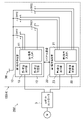
- FIG. 2 shows a schematic configuration diagram of the load drive control device
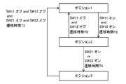
- FIG. 3 schematically shows the transition of the operation state of the enable switch device.
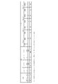
- FIG. 4 shows the determination result of the first state determination section. 2
- only the enable switch device 100 of the teaching pendant 4 is shown as a circuit diagram.
- the motors M are provided according to the number of the joint shafts 2b. Driving of each motor M is permitted or restricted according to the output signal of the enable switch device 100 .
- the enable switch device 100 has a first switch SW1, a second switch SW2, and a first signal processing section .
- the enable switch device 100 also has a power supply 30 . Note that the power supply 30 may be external to the enable switch device 100 .
- the first switch SW1 and the second switch SW2 are three-position switches, each having terminals a, b, and c.
- the terminal c is a common terminal and is connected to the power supply 30 respectively. That is, the first switch SW1 is connected in parallel with the second switch SW2.
- the first switch SW1 and the second switch SW2 depending on the operation of the operation switch 4a described above, whether the terminal c and the terminal a are in a conductive state or the terminal c and the terminal b are in a conductive state. to switch.
- a terminal connected to the power supply 30 through the terminal c has a high potential (hereinafter referred to as H potential), and a terminal electrically separated from the power supply 30 has a low potential (hereinafter referred to as L potential).
- the first signal processing unit 10 is a known CPU or computer.
- the first signal processing section 10 has at least a first signal input section 11 , a first state determination section 12 and a first state output section 13 .
- the first signal input section 11 receives output signals from the first switch SW1 and the second switch SW2 and inputs them to the first state determination section 12 .
- the output signal of the first switch SW1 is represented by a combination of the potential of the terminal a and the potential of the terminal b (see FIG. 4).
- the output signal of the second switch SW2 is represented by a combination of the potential of the terminal a and the potential of the terminal b (see FIG. 4).
- the first state determination section 12 determines the operating state of the enable switch device 100 based on the signal input from the first signal input section 11 . Based on the signal input from the first signal input section 11, the first state determination section 12 detects whether or not there is a failure in each of the first switch SW1 and the second switch SW2. These will be discussed later.
- the function of the first state determination unit 12 is realized by executing predetermined software in the first signal processing unit 10.
- the first state determination section 12 is a functional block in the first signal processing section 10 .
- the first state output section 13 outputs the operation state of the enable switch device 100 based on the determination result of the first state determination section 12 .
- both the first switch SW1 and the second switch SW2 are off.
- the enabling switch device 100 is in position 1 as shown in FIG.
- the first switch SW1 is turned off when the potential of the terminal a is H potential and the potential of the terminal b is L potential.
- the first switch SW1 is turned on.
- the second switch SW2 is turned off when the potential of the terminal a is H potential and the potential of the terminal b is L potential.
- the second switch SW2 is turned on.
- the enable switch device 100 When the operating state of the enable switch device 100 is position 1, the enable switch device 100 is in the OFF state.
- the first state output section 13 outputs a signal to the robot controller 3 . Since the robot controller 3 recognizes that the enable switch device 100 is in the OFF state, it sends a drive stop signal to the motor M. As a result, the drive control of the motor M becomes impossible, and the robot 2 does not operate.
- the enable switch device 100 When the operator operates the operation switch 4a, the enable switch device 100 is configured such that the first switch SW1 first transitions to the ON state. When the first switch SW1 is on and the second switch SW2 is off, it is assumed that the enabling switch device 100 is in position 2 as shown in FIG. Also, this state is sometimes called an intermediate operation state.
- the enable switch device 100 When the operating state of the enable switch device 100 is position 2, the enable switch device 100 is in the ON state.
- the first state output section 13 outputs a signal to the robot controller 3 . Since the robot controller 3 recognizes that the enable switch device 100 is on, it sends a drive permission signal to the motor M. As a result, the drive control of the motor M becomes possible, and the robot 2 performs a predetermined operation based on the teaching contents of the teaching pendant 4 .
- both the first switch SW1 and the second switch SW2 transition to the ON state.
- the operation switch 4a is gripped strongly.
- the operating state of the enable switch device 100 is at position 3, as shown in FIG. Also, this state is sometimes called a fully operational state.
- the enable switch device 100 When the operating state of the enable switch device 100 is position 3, the enable switch device 100 is in the OFF state.
- the first state output section 13 outputs a signal to the robot controller 3 . Since the robot controller 3 recognizes that the enable switch device 100 is in the OFF state, it sends a drive stop signal to the motor M. As a result, the drive control of the motor M becomes impossible, and the robot 2 does not operate.
- the first state determination unit 12 determines that the operating state of the enable switch device 100 does not correspond to any of positions 1-3.
- both the potentials of the terminal a and the terminal b may be H potential. In this case, it is considered that a short-circuit failure has occurred between the terminals a and b.
- both the potentials of the terminal a and the terminal b may be the L potential. In this case, the contact is stuck inside the second switch SW2, and it is considered that the contact is not in contact with either the terminal a or the terminal b, that is, an open failure has occurred.
- the first state determination unit 12 determines the presence and type of failure as described above from the output signals of the first switch SW1 and the second switch SW2. It should be noted that the output signal from the first state output unit 13 is information regarding the operating state of the enable switch device 100 . Failure information of the first switch SW1 and the second switch SW2, that is, information regarding the presence or absence of failure and its type is not directly included in the output signal. However, when the first switch SW1 and the second switch SW2 are not malfunctioning, the operating state of the enable switch device 100 does not correspond to any of the positions 1-3. In such a case, the enable switch device 100 is determined to be off.
- the robot controller 3 upon receiving the output signal, the robot controller 3 sends a drive stop signal to the motor M. As a result, the drive control of the motor M becomes impossible, and the robot 2 does not operate.
- Data transmission from the first state output unit 13 to the robot controller 3 may be performed by wired communication or wireless communication.
- the determination result of the first state determination unit 12 may be stored in a storage unit (not shown).
- the storage section may be outside the first signal processing section 10 .
- the information stored in the storage section includes not only the operating state of the enable switch device 100 but also failure information of the first switch SW1 and the second switch SW2.
- the enable switch device 100 can be completely set to position 1 (first position), which is in the OFF state when not operated, and to position 2 (second position), which is in the ON state during intermediate operation. When operated, they transition to position 3 (third position), which is in the OFF state.
- the enable switch device 100 includes at least a first switch SW1, a second switch SW2, and a first signal processing section .
- Each of the first switch SW1 and the second switch SW2 is a three-position switch. Also, the first switch SW1 is connected in parallel with the second switch SW2.
- the first signal processing unit 10 is configured to determine which of the positions 1 to 3 the operating state of the enable switch device 100 is based on the respective output signals of the first switch SW1 and the second switch SW2. ing. Further, the first signal processing unit 10 is configured to detect the presence or absence of a failure in each of the first switch SW1 and the second switch SW2.
- the operating state of the enable switch device 100 can be determined with a simple configuration. As a result, it is possible to prevent the operator from falling into a dangerous state due to the operator's operation error or the like. In addition, the robot 2 can be prevented from moving unintentionally, and the robot system 1 can be safely operated.
- the robot 2 connected to the enable switch device 100 can be prevented from operating unintentionally, and the robot system 1 can be operated safely.
- the teaching pendant 4 having the enable switch device 100 can be easily replaced and repaired. As a result, downtime and operating costs of the robot system 1 can be reduced.
- the first signal processing section 10 includes at least a first signal input section 11 , a first state determination section 12 and a first state output section 13 .
- the first signal input section 11 receives the output signals of the first switch SW1 and the second switch SW2 and inputs them to the first state determination section.
- the first state determination section 12 determines which of positions 1 to 3 the enable switch device 100 is in the operating state. Also, the first state determination unit 12 detects the presence or absence of a failure in each of the first switch SW1 and the second switch SW2.
- the first state output section 13 outputs the operation state of the enable switch device 100 to the robot controller 3 based on the determination result of the first state determination section 12 .
- the first state output unit 13 may output failure information in each of the first switch SW1 and the second switch SW2 to the robot controller 3 as necessary.
- the first signal processing unit 10 By configuring the first signal processing unit 10 in this manner, it is possible to easily determine the operating state of the enable switch device 100, the presence or absence of a failure of the first switch SW1 or the second switch SW2, and the like.
- predetermined software is executed by the first signal processing unit 10 to determine the operating state of the enable switch device 100, the presence or absence of failure of the first switch SW1 and the second switch SW2, and the like. By doing so, it is possible to reduce the number of relays used compared to the conventional configuration disclosed in Patent Document 1. As a result, the replacement cycle of the enable switch device 100 and thus the teaching pendant 4 can be lengthened. Also, downtime and operating costs of the robot system 1 can be reduced.
- a load drive control device 200 includes at least an enable switch device 100 and a robot controller (control device) 3 .
- the robot controller 3 is configured to communicate with the enable switch device 100 .
- the robot controller 3 transmits a drive permission signal to the motor (load) M configured to communicate with the robot controller 3 .
- the robot controller 3 transmits a drive stop signal to the motor M.
- the robot controller 3 permits or restricts the driving of the motor M according to the state of the enable switch device 100 .
- the robot 2 can be prevented from moving unintentionally, and the robot system 1 can be safely operated.
- the robot controller 3 sends a drive stop signal to the motor M.
- the robot 2 connected to the enable switch device 100 can be prevented from operating unintentionally, and the robot system 1 can be operated safely.
- the teaching pendant 4 having the enable switch device 100 can be easily replaced and repaired, and the downtime and operating costs of the robot system 1 can be reduced.
- FIG. 5 schematically shows the transition of the operation state of the enable switch device according to this embodiment.
- the same parts as in Embodiment 1 are given the same reference numerals, and detailed explanations thereof are omitted.
- the enable switch device 100 of this embodiment differs from the enable switch device 100 of Embodiment 1 in the following points.
- the first state determination unit 12 detects the state transition and then After the transition time T1 has elapsed, it is determined that the operating state of the enable switch device 100 has transitioned.
- the first state determination unit 12 detects the state transition and after the transition time T1 has elapsed, the enable switch device 100 It is determined that the operation state of 100 has changed.
- the transition time T1 is set to 24 msec in this embodiment, it is not particularly limited to this.
- the first state determination unit 12 determines that immediately after detecting the state transition, in this case, the transition time T0 ( ⁇ T1 ), it is determined that the operation state of the enable switch device 100 has changed.
- the timing to start driving the motor M can be delayed by the transition time T1 immediately after the enable switch device 100 enters the intermediate operation state.
- the enable switch device 100 may further transition to the non-operated state.
- the robot controller 3 can quickly transmit a drive stop signal to the robot 2 by determining that the operation state of the enable switch device 100 has transitioned immediately after detecting the state transition, thereby enabling the robot 2 to operate. is stopped. This enhances worker safety.
- FIG. 6 shows a schematic configuration diagram of the load drive control device according to the present embodiment, and FIG. 7 schematically shows transition of the operation state of the enable switch device.
- FIG. 8 shows the determination results of the first state determination section and the second state determination section. It should be noted that FIG. 6 shows only the enable switch device 100 of the teaching pendant 4 as a circuit diagram, as in the first embodiment. Similarly, FIG. 6 shows only the motor M connected to one joint shaft 2b.
- the enable switch device 100 of this embodiment differs from the enable switch device 100 of Embodiment 1 in the following points.
- the enable switch device 100 includes at least first to fourth switches SW11 to SW22, a first signal processing section 10, and a second signal processing section 20.
- Each of the first to fourth switches SW11 to SW22 is a 3-position switch.
- a terminal c is a common terminal and is connected to the power supply 30, respectively. That is, the first to fourth switches SW11 to SW22 are connected in parallel with each other. Also, the operations of the first to fourth switches SW11 to SW22 are the same as the operations of the first switch SW1 and the second switch SW2 shown in the first embodiment.
- the first signal processing unit 10 is configured to determine the state of each of the first switch SW11 and the second switch SW21. That is, it is configured to determine whether the first switch SW11 and the second switch SW21 are in an ON state or an OFF state. Also, the first signal processing unit 10 is configured to detect whether or not there is a failure in the first switch SW11 and the second switch SW21.
- the first signal processing section 10 has at least a first signal input section 11, a first state determination section 12, and a first state output section 13, as in the first embodiment. Since the function of the first signal input section 11 is the same as that shown in the first embodiment, the explanation is omitted.
- the first state determination section 12 determines the respective states of the first switch SW11 and the second switch SW21 based on the signal input from the first signal input section 11 . That is, it is determined whether the first switch SW11 and the second switch SW21 are in the ON state or the OFF state. Based on the signal input from the first signal input section 11, the first state determination section 12 detects whether or not the first switch SW11 and the second switch SW21 are faulty. Here, the presence or absence and type of failure of the first switch SW11 and the second switch SW21 are detected by a method similar to that shown in the first embodiment. For example, in the first switch SW11, if the potential of the terminal a and the potential of the terminal b are both H potential, it is determined that the first switch SW11 has a short-circuit fault. In the second switch SW21, if both the potential of the terminal a and the potential of the terminal b are L potential, it is determined that the second switch SW21 has an open fault.
- the first state output unit 13 Based on the determination result of the first state determination unit 12, the first state output unit 13 outputs information about the respective states of the first switch SW11 and the second switch SW21. , and output information to the robot controller 3 as to whether they are on or off. Note that the first state output unit 13 may output failure information of each of the first switch SW11 and the second switch SW21 to the robot controller 3 .
- the function and configuration of the second signal processing section 20 are the same as those of the first signal processing section 10, respectively. However, the second signal processing section 20 handles input signals of the third switch SW12 and the fourth switch SW22.
- the second signal processing section 20 is configured to determine the state of each of the third switch SW12 and the fourth switch SW22. That is, it is configured to determine whether the third switch SW12 and the fourth switch SW22 are on or off. Further, the second signal processing section 20 is configured to detect the presence or absence of failure in each of the third switch SW12 and the fourth switch SW22.
- the second signal processing section 20 has at least a second signal input section 21 , a second state determination section 22 and a second state output section 23 .
- the second signal input section 21 receives output signals from the third switch SW12 and the fourth switch SW22 and inputs them to the second state determination section 22 .
- the second state determination section 22 determines the respective states of the third switch SW12 and the fourth switch SW22 based on the signal input from the second signal input section 21 . That is, it is determined whether the third switch SW12 and the fourth switch SW22 are in the ON state or the OFF state. Further, the second state determination section 22 detects whether or not the third switch SW12 and the fourth switch SW22 are out of order based on the signal input from the second signal input section 21 .
- the second state output unit 23 outputs information about the states of the third switch SW12 and the fourth switch SW22 based on the determination result of the second state determination unit 22, that is, the state of the third switch SW12 and the fourth switch SW22. , and output information to the robot controller 3 as to whether they are on or off.
- the second state output unit 23 may output failure information of each of the third switch SW12 and the fourth switch SW22 to the robot controller 3.
- the enable switch device 100 determines the operating state of the enable switch device 100 based on the determination result of the first signal processing section 10 and the determination result of the second signal processing section 20 .
- the first signal processing unit 10 determines only the respective states of the first switch SW11 and the second switch SW21.
- the second signal processing unit 20 determines only the respective states of the third switch SW12 and the fourth switch SW22. Therefore, based on the determination result of the first signal processing section 10 and the determination result of the second signal processing section 20, the operation state of the enable switch device 100 is finally determined.
- the operating state of the enable switch device 100 is position 2 (second position). It is determined that there is That is, the enable switch device 100 is determined to be in the ON state (intermediate operation state).
- the timing at which either the second switch SW21 or the fourth switch SW22 is turned on is the timing at which the operating state of the enable switch device 100 is determined to be the position 3 .
- the first signal processing section 10 and the second signal processing section 20 are configured to be able to communicate with each other.
- serial communication is performed between the first signal processing section 10 and the second signal processing section 20 .
- these determinations may be performed by the first signal processing unit 10, for example, the first state determination unit 12, which receives the determination result of the second state determination unit 22.
- these determinations may be performed by the second signal processing section 20, for example, the second state determination section 22, which receives the determination result of the first state determination section 12.
- either the first signal processing unit 10 or the second signal processing unit 20 or another determination unit may be provided inside the enable switch device 100 .
- the other determination section receives the determination result of the first signal processing section 10 and the determination result of the second signal processing section 20 and determines the state of the enable switch device 100 .
- the state of the enable switch device 100 may be determined by the robot controller 3 that receives the output signal of the first state output section 13 and the output signal of the second state output section 23 .
- the operating state of the enable switch device 100 can be determined with a simple configuration. As a result, it is possible to prevent the operator from falling into a dangerous state due to the operator's operation error or the like. In addition, the robot 2 can be prevented from moving unintentionally, and the robot system 1 can be safely operated.
- the presence or absence of a failure in the first to fourth switches SW1 to SW22 provided inside the enable switch device 100 and the type thereof can be easily detected.
- the robot 2 connected to the enable switch device 100 can be prevented from operating unintentionally, and the robot system 1 can be operated safely.
- the teaching pendant 4 having the enable switch device 100 can be easily replaced and repaired. As a result, downtime and operating costs of the robot system 1 can be reduced.
- the enable switch device 100 shown in the present embodiment is a so-called duplex circuit that includes two sets of combination circuits of the two switches shown in the first embodiment and the signal processing unit. Further, the enable switch device 100 shown in this embodiment is configured to correctly determine the operating state of the enable switch device 100 only when both of the two combination circuits are functioning normally.
- the first signal processing section 10 and the second signal processing section 20 are configured to be able to communicate with each other. Further, when the determination result in the first signal processing section 10 and the determination result in the second signal processing section 20 do not match, it is determined that the enable switch device 100 is in the OFF state.
- the safety of workers can be improved.
- the robot 2 can be prevented from moving unintentionally, and the robot system 1 can be safely operated.
- the robot controller 3 transmits a drive stop signal to the motor M. .
- the robot 2 connected to the enable switch device 100 can be prevented from operating unintentionally, and the robot system 1 can be operated safely. Further, it is possible to easily detect the presence or absence of a failure in the first to fourth switches SW11 to SW22 and the type thereof. As a result, the teaching pendant 4 having the enable switch device 100 can be easily replaced and repaired, and the downtime and operating costs of the robot system 1 can be reduced.
- FIG. 9 schematically shows the transition of the operation state of the enable switch device according to this embodiment.
- the configuration of the enable switch device 100 of this embodiment is the same as that shown in the third embodiment. In other words, the enable switch device 100 is provided with a redundant circuit.
- the enable switch device 100 of the present embodiment determines the operation state of the enable switch device 100 after a predetermined transition time has elapsed from detection of the state transition, as in the second embodiment. , it is determined that the operation state of the enable switch device 100 has changed.
- the first state determination unit 12 and the second state determination unit 22 detect the transition time T2 after detecting the state transition. Later, it is determined that the operation state of the enable switch device 100 has changed.
- the first state determination unit 12 and the second state determination unit 22 detect the enable state after the transition time T2 has elapsed from detection of the state transition. It is determined that the operation state of the switch device 100 has changed.
- transition time T2 may be the same as the transition time T1 shown in the second embodiment, or may be different.
- the enable switch device 100 of the present embodiment includes first to fourth switches SW11 to SW22, and considering their reaction times, the transition time T2 is preferably longer than the transition time T1.
- the first state determination unit 12 and the second state determination unit 22 immediately detect this state transition. , it is determined that the operation state of the enable switch device 100 has changed after the transition time T0 ( ⁇ T1, T2) has elapsed.
- the timing to start driving the motor M can be delayed by the transition time T2 from immediately after the enabling switch device 100 enters the intermediate operation state.
- the enable switch device 100 may further transition to the non-operated state.
- the robot controller 3 can quickly transmit a drive stop signal to the robot 2 by determining that the operation state of the enable switch device 100 has transitioned immediately after detecting the state transition, thereby enabling the robot 2 to operate. is stopped. This enhances worker safety.
- either the first state determination section 12 or the second state determination section 22 may finally determine the state of the enable switch device 100 .
- the state of the enable switch device 100 may be finally determined by another determination unit (not shown) provided inside the enable switch device 100 .
- the enable switch device 100 and the load drive control device 200 of the specification of the present application are preferably used by being connected to the robot 2 installed in the industrial machine described above.
- the enable switch device of the present disclosure can determine the operation state with a simple configuration, and can detect failure of the internal 3-position switch, so it is useful when applied to industrial machines having robots.
Landscapes
- Engineering & Computer Science (AREA)
- Robotics (AREA)
- Mechanical Engineering (AREA)
- Numerical Control (AREA)
Abstract
Description
[ロボットシステムの構成]
図1は、本実施形態に係るロボットシステムの概略構成図を示し、ロボットシステム1は、ロボット2と負荷駆動制御装置200とを有している。また、負荷駆動制御装置200は、ロボットコントローラ(制御装置)3とティーチングペンダント4とを有している。 (Embodiment 1)
[Configuration of robot system]
FIG. 1 shows a schematic configuration diagram of a robot system according to this embodiment, and the
図2は、負荷駆動制御装置の概略構成図を示し、図3は、イネーブルスイッチ装置の操作状態の遷移を模式的に示す。図4は、第1状態判定部での判定結果を示す。なお、図2において、ティーチングペンダント4のうち、イネーブルスイッチ装置100のみを回路図として示している。また、説明の便宜上、1つの関節軸2bに接続されたモータMのみを図示しているが、前述したように、関節軸2bの数に応じてモータMが設けられている。それぞれのモータMの駆動がイネーブルスイッチ装置100の出力信号に応じて許可され、また、規制される。 [Configuration of load drive control device and enable switch device]
FIG. 2 shows a schematic configuration diagram of the load drive control device, and FIG. 3 schematically shows the transition of the operation state of the enable switch device. FIG. 4 shows the determination result of the first state determination section. 2, only the enable
以上説明したように、本実施形態に係るイネーブルスイッチ装置100は、非操作時にオフ状態であるポジション1(第1ポジション)に、中間操作時にオン状態であるポジション2(第2ポジション)に、完全操作時にオフ状態であるポジション3(第3ポジション)にそれぞれ遷移する。 [Effects, etc.]
As described above, the enable
図5は、本実施形態に係るイネーブルスイッチ装置の操作状態の遷移を模式的に示す。なお、説明の便宜上、図5及び以降に示す各図面において、実施形態1と同様の箇所については、同一の符号を付して詳細な説明を省略する。 (Embodiment 2)
FIG. 5 schematically shows the transition of the operation state of the enable switch device according to this embodiment. For convenience of explanation, in FIG. 5 and subsequent drawings, the same parts as in
図6は、本実施形態に係る負荷駆動制御装置の概略構成図を示し、図7は、イネーブルスイッチ装置の操作状態の遷移を模式的に示す。図8は、第1状態判定部及び第2状態判定部での判定結果を示す。なお、図6において、ティーチングペンダント4のうち、イネーブルスイッチ装置100のみを回路図として示していることは、実施形態1に示したのと同様である。同様に、図6において、1つの関節軸2bに接続されたモータMのみを図示している。 (Embodiment 3)
FIG. 6 shows a schematic configuration diagram of the load drive control device according to the present embodiment, and FIG. 7 schematically shows transition of the operation state of the enable switch device. FIG. 8 shows the determination results of the first state determination section and the second state determination section. It should be noted that FIG. 6 shows only the enable
図9は、本実施形態に係るイネーブルスイッチ装置の操作状態の遷移を模式的に示す。 (Embodiment 4)
FIG. 9 schematically shows the transition of the operation state of the enable switch device according to this embodiment.
2 ロボット
2a ロボットアーム
2b 関節軸
3 ロボットコントローラ(制御装置)
4 ティーチングペンダント
4a 操作スイッチ
5 通信ケーブル
10 第1信号処理部
11 第1信号入力部
12 第1状態判定部
13 第1状態出力部
20 第2信号処理部
21 第2信号入力部
22 第2状態判定部
23 第2状態出力部
30 電源
100 イネーブルスイッチ装置
200 負荷駆動制御装置
M モータ(負荷)
SW1 第1スイッチ
SW2 第2スイッチ
SW11 第1スイッチ
SW21 第2スイッチ
SW12 第3スイッチ
SW22 第4スイッチ 1
4
SW1 First switch SW2 Second switch SW11 First switch SW21 Second switch SW12 Third switch SW22 Fourth switch
Claims (12)
- 非操作時にオフ状態である第1ポジションに、中間操作時にオン状態である第2ポジションに、完全操作時にオフ状態である第3ポジションにそれぞれ遷移するイネーブルスイッチ装置であって、
第1スイッチと、第2スイッチと、第1信号処理部と、を少なくとも備え、
前記第1スイッチ及び前記第2スイッチは、それぞれ3ポジションスイッチであり、
前記第1信号処理部は、前記第1スイッチ及び前記第2スイッチのそれぞれの出力信号に基づいて、前記イネーブルスイッチ装置の操作状態が前記第1~第3ポジションのいずれであるかを判定するとともに、前記第1スイッチ及び前記第2スイッチのそれぞれにおける故障の有無を検出可能に構成されていることを特徴とするイネーブルスイッチ装置。 An enable switch device that transitions to a first position that is in an OFF state when not operated, a second position that is in an ON state in an intermediate operation, and a third position that is in an OFF state in a full operation,
At least a first switch, a second switch, and a first signal processing unit,
each of the first switch and the second switch is a three-position switch;
The first signal processing unit determines which of the first to third positions the enable switch device is in, based on the output signals of the first switch and the second switch. , an enable switch device configured to be able to detect the presence or absence of a failure in each of said first switch and said second switch. - 請求項1に記載のイネーブルスイッチ装置において、
前記第1信号処理部は、第1信号入力部と第1状態判定部と第1状態出力部とを少なくとも備え、
前記第1信号入力部は、前記第1スイッチ及び前記第2スイッチのそれぞれの出力信号を受け取って、前記第1状態判定部に入力し、
前記第1状態判定部は、前記第1信号入力部から入力された信号に基づいて、前記イネーブルスイッチ装置の操作状態が前記第1~第3ポジションのいずれであるかを判定するとともに、前記第1スイッチ及び前記第2スイッチのそれぞれにおける故障の有無を検出し、
前記第1状態出力部は、前記第1状態判定部での判定結果に基づいて、前記イネーブルスイッチ装置の操作状態を出力することを特徴とするイネーブルスイッチ装置。 The enabling switch device of claim 1, wherein
The first signal processing unit includes at least a first signal input unit, a first state determination unit, and a first state output unit,
the first signal input unit receives output signals from the first switch and the second switch and inputs them to the first state determination unit;
The first state determination section determines which of the first to third positions the operating state of the enable switch device is, based on the signal input from the first signal input section. Detecting the presence or absence of a failure in each of the first switch and the second switch,
The enable switch device, wherein the first state output section outputs the operation state of the enable switch device based on the determination result of the first state determination section. - 請求項2に記載のイネーブルスイッチ装置において、
前記第1状態判定部は、前記イネーブルスイッチ装置の操作状態が前記第1ポジションから前記第2ポジションに遷移した場合及び前記第3ポジションから前記第1ポジションに遷移した場合のそれぞれにおいて、状態遷移を検出してから所定時間の経過後に、前記イネーブルスイッチ装置の操作状態が遷移したと判定することを特徴とするイネーブルスイッチ装置。 The enabling switch device according to claim 2, wherein
The first state determination unit determines the state transition when the operating state of the enable switch device transitions from the first position to the second position and from the third position to the first position. An enable switch device, wherein it is determined that the operating state of the enable switch device has changed after a predetermined time has passed since the detection. - 請求項3に記載のイネーブルスイッチ装置において、
前記第1状態判定部は、前記イネーブルスイッチ装置の操作状態が前記第2ポジションから前記第1ポジションまたは前記第3ポジションのいずれかに遷移した場合、状態遷移の検出直後に前記イネーブルスイッチ装置の操作状態が遷移したと判定することを特徴とするイネーブルスイッチ装置。 The enabling switch device according to claim 3, wherein
The first state determination unit is configured to operate the enable switch device immediately after detecting the state transition when the operating state of the enable switch device transitions from the second position to either the first position or the third position. An enable switch device that determines that a state has changed. - 非操作時にオフ状態である第1ポジションに、中間操作時にオン状態である第2ポジションに、完全操作時にオフ状態である第3ポジションにそれぞれ遷移するイネーブルスイッチ装置であって、
第1~第4スイッチと、第1信号処理部と、第2信号処理部と、を少なくとも備え、
前記第1~第4スイッチは、それぞれ3ポジションスイッチであり、
前記第1信号処理部は、前記第1スイッチ及び前記第2スイッチのそれぞれの状態を判定するとともに、それぞれの故障の有無を検出可能に構成され、
前記第2信号処理部は、前記第3スイッチ及び前記第4スイッチのそれぞれの状態を判定するとともに、それぞれの故障の有無を検出可能に構成され、
前記第1信号処理部の判定結果と前記第2信号処理部の判定結果とに基づいて、前記イネーブルスイッチ装置の操作状態を判定することを特徴とするイネーブルスイッチ装置。 An enable switch device that transitions to a first position that is in an OFF state when not operated, a second position that is in an ON state in an intermediate operation, and a third position that is in an OFF state in a full operation,
At least comprising first to fourth switches, a first signal processing unit, and a second signal processing unit,
each of the first to fourth switches is a 3-position switch;
The first signal processing unit is configured to determine the states of each of the first switch and the second switch and to detect the presence or absence of a failure in each,
The second signal processing unit is configured to determine the states of each of the third switch and the fourth switch and to detect the presence or absence of failure of each,
An enable switch device that determines an operation state of the enable switch device based on a determination result of the first signal processing section and a determination result of the second signal processing section. - 請求項5に記載のイネーブルスイッチ装置において、
前記第1信号処理部は、第1信号入力部と第1状態判定部と第1状態出力部とを少なくとも備え、
前記第1信号入力部は、前記第1スイッチ及び前記第2スイッチのそれぞれの出力信号を受け取って、前記第1状態判定部に入力し、
前記第1状態判定部は、前記第1信号入力部から入力された信号に基づいて、前記第1スイッチ及び前記第2スイッチのそれぞれの状態を判定するとともに、それぞれの故障の有無を検出し、
前記第1状態出力部は、前記第1状態判定部での判定結果に基づいて、前記第1スイッチ及び前記第2スイッチのそれぞれの状態に関する情報を出力し、
前記第2信号処理部は、第2信号入力部と第2状態判定部と第2状態出力部とを少なくとも備え、
前記第2信号入力部は、前記第3スイッチ及び前記第4スイッチのそれぞれの出力信号を受け取って、前記第2状態判定部に入力し、
前記第2状態判定部は、前記第2信号入力部から入力された信号に基づいて、前記第3スイッチ及び前記第4スイッチのそれぞれの状態を判定するとともに、それぞれの故障の有無を検出し、
前記第2状態出力部は、前記第2状態判定部での判定結果に基づいて、前記第3スイッチ及び前記第4スイッチのそれぞれの状態に関する情報を出力し、
前記第1信号処理部と前記第2信号処理部とは相互に通信可能に構成されており、
前記第1信号処理部での判定結果と前記第2信号処理部での判定結果とが一致した場合は、当該判定結果が前記イネーブルスイッチ装置の操作状態であると判定され、
前記第1信号処理部での判定結果と前記第2信号処理部での判定結果とが一致しない場合は、前記イネーブルスイッチ装置がオフ状態であると判定されることを特徴とするイネーブルスイッチ装置。 The enabling switch device according to claim 5, wherein
The first signal processing unit includes at least a first signal input unit, a first state determination unit, and a first state output unit,
the first signal input unit receives output signals from the first switch and the second switch and inputs them to the first state determination unit;
The first state determination unit determines the states of each of the first switch and the second switch based on the signal input from the first signal input unit, and detects the presence or absence of each failure,
The first state output unit outputs information regarding the state of each of the first switch and the second switch based on the determination result of the first state determination unit,
The second signal processing unit includes at least a second signal input unit, a second state determination unit, and a second state output unit,
the second signal input unit receives output signals from the third switch and the fourth switch and inputs them to the second state determination unit;
The second state determination unit determines the states of each of the third switch and the fourth switch based on the signal input from the second signal input unit, and detects the presence or absence of each failure,
the second state output unit outputs information regarding the state of each of the third switch and the fourth switch based on the determination result of the second state determination unit;
The first signal processing unit and the second signal processing unit are configured to be able to communicate with each other,
When the determination result of the first signal processing unit and the determination result of the second signal processing unit match, it is determined that the determination result is the operating state of the enable switch device,
The enable switch device, wherein the enable switch device is determined to be in an OFF state when the determination result of the first signal processing section and the determination result of the second signal processing section do not match. - 請求項6に記載のイネーブルスイッチ装置において、
前記第1状態判定部及び前記第2状態判定部は、前記イネーブルスイッチ装置の操作状態が前記第1ポジションから前記第2ポジションに遷移した場合及び前記第3ポジションから前記第1ポジションに遷移した場合のそれぞれにおいて、状態遷移を検出してから所定時間の経過後に、前記イネーブルスイッチ装置の操作状態が遷移したと判定することを特徴とするイネーブルスイッチ装置。 The enabling switch device according to claim 6, wherein
The first state determination unit and the second state determination unit determine when the operation state of the enable switch device transitions from the first position to the second position and when the operation state of the enable switch device transitions from the third position to the first position. 3, wherein it is determined that the operation state of the enable switch device has changed after a predetermined time has passed since the state transition was detected. - 請求項7に記載のイネーブルスイッチ装置において、
前記第1状態判定部及び前記第2状態判定部は、前記イネーブルスイッチ装置の操作状態が前記第2ポジションから前記第1ポジションまたは前記第3ポジションのいずれかに遷移した場合、状態遷移の検出直後に前記イネーブルスイッチ装置の操作状態が遷移したと判定することを特徴とするイネーブルスイッチ装置。 The enabling switch device according to claim 7, wherein
The first state determination section and the second state determination section immediately after detecting the state transition when the operating state of the enable switch device transitions from the second position to either the first position or the third position. and determining that the operation state of the enable switch device has changed to . - 請求項1ないし4のいずれか1項に記載のイネーブルスイッチ装置と、
前記イネーブルスイッチ装置と通信可能に構成された制御装置とを、少なくとも備え、
前記イネーブルスイッチ装置がオン状態であると判定された場合、前記制御装置は、前記制御装置と通信可能に構成された負荷に駆動許可信号を送信し、
前記イネーブルスイッチ装置がオフ状態であると判定された場合、前記制御装置は、前記負荷に駆動停止信号を送信することを特徴とする負荷駆動制御装置。 an enabling switch device according to any one of claims 1 to 4;
At least a control device configured to communicate with the enable switch device,
When the enable switch device is determined to be in an ON state, the control device transmits a drive permission signal to a load configured to communicate with the control device;
A load drive control device, wherein the control device transmits a drive stop signal to the load when it is determined that the enable switch device is in an off state. - 請求項9に記載の負荷駆動制御装置において、
前記第1スイッチ及び前記第2スイッチのいずれかに故障があると検出された場合、前記制御装置は、前記負荷に駆動停止信号を送信することを特徴とする負荷駆動制御装置。 In the load drive control device according to claim 9,
A load drive control device, wherein the control device transmits a drive stop signal to the load when a failure is detected in either the first switch or the second switch. - 請求項5ないし8のいずれか1項に記載のイネーブルスイッチ装置と、
前記イネーブルスイッチ装置と通信可能に構成された制御装置とを、少なくとも備え、
前記イネーブルスイッチ装置がオン状態であると判定された場合、前記制御装置は、前記制御装置と通信可能に構成された負荷に駆動許可信号を送信し、
前記イネーブルスイッチ装置がオフ状態であると判定された場合、前記制御装置は、前記負荷に駆動停止信号を送信することを特徴とする負荷駆動制御装置。 an enabling switch device according to any one of claims 5 to 8;
At least a control device configured to communicate with the enable switch device,
When the enable switch device is determined to be in an ON state, the control device transmits a drive permission signal to a load configured to communicate with the control device;
A load drive control device, wherein the control device transmits a drive stop signal to the load when it is determined that the enable switch device is in an off state. - 請求項11に記載の負荷駆動制御装置において、
前記第1~第4スイッチのいずれかに故障があると検出された場合、前記制御装置は、前記負荷に駆動停止信号を送信することを特徴とする負荷駆動制御装置。 In the load drive control device according to claim 11,
The load drive control device, wherein the control device transmits a drive stop signal to the load when it is detected that any one of the first to fourth switches has a failure.
Priority Applications (3)
| Application Number | Priority Date | Filing Date | Title |
|---|---|---|---|
| CN202280028162.9A CN117222501A (en) | 2021-06-03 | 2022-05-23 | Enable switching device and load drive control device provided with same |
| JP2023525734A JP7554976B2 (en) | 2021-06-03 | 2022-05-23 | Enable switch device and load drive control device equipped with the same |
| US18/468,717 US20240001563A1 (en) | 2021-06-03 | 2023-09-17 | Enable switch device and load drive control apparatus equipped with same |
Applications Claiming Priority (2)
| Application Number | Priority Date | Filing Date | Title |
|---|---|---|---|
| JP2021-093409 | 2021-06-03 | ||
| JP2021093409 | 2021-06-03 |
Related Child Applications (1)
| Application Number | Title | Priority Date | Filing Date |
|---|---|---|---|
| US18/468,717 Continuation US20240001563A1 (en) | 2021-06-03 | 2023-09-17 | Enable switch device and load drive control apparatus equipped with same |
Publications (1)
| Publication Number | Publication Date |
|---|---|
| WO2022255138A1 true WO2022255138A1 (en) | 2022-12-08 |
Family
ID=84323291
Family Applications (1)
| Application Number | Title | Priority Date | Filing Date |
|---|---|---|---|
| PCT/JP2022/021056 WO2022255138A1 (en) | 2021-06-03 | 2022-05-23 | Enable switch device and load drive control apparatus equipped with same |
Country Status (3)
| Country | Link |
|---|---|
| US (1) | US20240001563A1 (en) |
| CN (1) | CN117222501A (en) |
| WO (1) | WO2022255138A1 (en) |
Citations (9)
| Publication number | Priority date | Publication date | Assignee | Title |
|---|---|---|---|---|
| JPH0890485A (en) * | 1994-09-19 | 1996-04-09 | Yaskawa Electric Corp | On-hand operator |
| JPH11329136A (en) * | 1998-05-15 | 1999-11-30 | Yaskawa Electric Corp | Deadman switch |
| JP2002042606A (en) * | 2000-07-31 | 2002-02-08 | Idec Izumi Corp | Push button switch, and teaching pendant therewith |
| JP2002083522A (en) * | 2000-09-06 | 2002-03-22 | Idec Izumi Corp | Enable device for teach pendant |
| JP2003323832A (en) * | 2002-05-02 | 2003-11-14 | Omron Corp | Enable switch |
| JP2004327068A (en) * | 2003-04-21 | 2004-11-18 | Idec Izumi Corp | Three-position enable device |
| JP2005070922A (en) * | 2003-08-21 | 2005-03-17 | Yaskawa Electric Corp | Operation permission device of automatic machine |
| JP2006244853A (en) * | 2005-03-03 | 2006-09-14 | Shinko Denki Kk | Enable switch |
| JP2016062727A (en) * | 2014-09-17 | 2016-04-25 | 新晃電機株式会社 | Enable switch |
-
2022
- 2022-05-23 WO PCT/JP2022/021056 patent/WO2022255138A1/en active Application Filing
- 2022-05-23 CN CN202280028162.9A patent/CN117222501A/en active Pending
-
2023
- 2023-09-17 US US18/468,717 patent/US20240001563A1/en active Pending
Patent Citations (9)
| Publication number | Priority date | Publication date | Assignee | Title |
|---|---|---|---|---|
| JPH0890485A (en) * | 1994-09-19 | 1996-04-09 | Yaskawa Electric Corp | On-hand operator |
| JPH11329136A (en) * | 1998-05-15 | 1999-11-30 | Yaskawa Electric Corp | Deadman switch |
| JP2002042606A (en) * | 2000-07-31 | 2002-02-08 | Idec Izumi Corp | Push button switch, and teaching pendant therewith |
| JP2002083522A (en) * | 2000-09-06 | 2002-03-22 | Idec Izumi Corp | Enable device for teach pendant |
| JP2003323832A (en) * | 2002-05-02 | 2003-11-14 | Omron Corp | Enable switch |
| JP2004327068A (en) * | 2003-04-21 | 2004-11-18 | Idec Izumi Corp | Three-position enable device |
| JP2005070922A (en) * | 2003-08-21 | 2005-03-17 | Yaskawa Electric Corp | Operation permission device of automatic machine |
| JP2006244853A (en) * | 2005-03-03 | 2006-09-14 | Shinko Denki Kk | Enable switch |
| JP2016062727A (en) * | 2014-09-17 | 2016-04-25 | 新晃電機株式会社 | Enable switch |
Also Published As
| Publication number | Publication date |
|---|---|
| JPWO2022255138A1 (en) | 2022-12-08 |
| US20240001563A1 (en) | 2024-01-04 |
| CN117222501A (en) | 2023-12-12 |
Similar Documents
| Publication | Publication Date | Title |
|---|---|---|
| JP3944156B2 (en) | Emergency stop circuit | |
| JP4659690B2 (en) | Machine control device | |
| US6832121B1 (en) | Device for monitoring safety-relevant processes in machines | |
| JP2005522637A (en) | Device for fail-safe disconnection of electrical loads | |
| JP2003502981A (en) | Safety-related automation bus systems | |
| JP2004148488A (en) | Robot control device | |
| US6826433B1 (en) | Failsafe data output system and automation system having the same | |
| US10965225B2 (en) | Motor control device | |
| CN112660158B (en) | Driving assistance control system | |
| JP2005025479A (en) | Safety relay system and control method for safety relay | |
| JP4238705B2 (en) | Safety controller | |
| JP7014140B2 (en) | Electromagnetic brake control device and control device | |
| WO2022255138A1 (en) | Enable switch device and load drive control apparatus equipped with same | |
| JP7554976B2 (en) | Enable switch device and load drive control device equipped with the same | |
| CN114347025B (en) | Cooperative robot function safety control circuit, control method and cooperative robot | |
| JP4238687B2 (en) | Safety controller and system using the same | |
| KR20120042991A (en) | Safety device for elevator | |
| JPWO2022255138A5 (en) | ||
| CN110605712B (en) | Robot system and safety control device | |
| JP5059919B2 (en) | Machine control device | |
| US20050052083A1 (en) | Method for identifying faulty antivalent key or switch signals | |
| JP4239784B2 (en) | Distributed control device | |
| JP4238690B2 (en) | Setting structure and safety controller using it | |
| US20230415335A1 (en) | Robot system, method for controlling robot system, method for manufacturing product using robot system, control program, and recording medium | |
| WO2023157365A1 (en) | Functional safety device |
Legal Events
| Date | Code | Title | Description |
|---|---|---|---|
| 121 | Ep: the epo has been informed by wipo that ep was designated in this application |
Ref document number: 22813878 Country of ref document: EP Kind code of ref document: A1 |
|
| WWE | Wipo information: entry into national phase |
Ref document number: 2023525734 Country of ref document: JP |
|
| WWE | Wipo information: entry into national phase |
Ref document number: 202280028162.9 Country of ref document: CN |
|
| NENP | Non-entry into the national phase |
Ref country code: DE |
|
| 122 | Ep: pct application non-entry in european phase |
Ref document number: 22813878 Country of ref document: EP Kind code of ref document: A1 |