JP2005025479A - Safety relay system and control method for safety relay - Google Patents
Safety relay system and control method for safety relay Download PDFInfo
- Publication number
- JP2005025479A JP2005025479A JP2003189856A JP2003189856A JP2005025479A JP 2005025479 A JP2005025479 A JP 2005025479A JP 2003189856 A JP2003189856 A JP 2003189856A JP 2003189856 A JP2003189856 A JP 2003189856A JP 2005025479 A JP2005025479 A JP 2005025479A
- Authority
- JP
- Japan
- Prior art keywords
- safety
- unit
- input
- manual
- output
- Prior art date
- Legal status (The legal status is an assumption and is not a legal conclusion. Google has not performed a legal analysis and makes no representation as to the accuracy of the status listed.)
- Pending
Links
Images


Abstract
Description
【0001】
【発明の属する技術分野】
本発明は、例えば安全確認等に関わる複数の入力条件が全て成立した場合に限り対象となる負荷を駆動する等の用途に好適な、信頼性の高い安全リレーシステムに関する。
【0002】
【従来の技術】
各方面における安全対策の必要性から、安全対策機器が利用されている。例えば、製造現場においては工作機械やプレス機械、ロボット、包装機械、昇降装置等が使用されており、これらの機器から作業者を保護するために様々な安全対策が必要となる。例えば、異常発生時に機器への電源供給を断つことで機械的な動作を停止させ、作業者の安全を確保する。このようなシステムの構築においては、安全リレー装置が利用されている。
【0003】
安全リレー装置は、電気接点を開閉して通電を制御する。安全リレー装置には、例えば強制ガイド付リレーを複数個内蔵し、加えて自己保持機能、リレー接点の二重化、リレーのNC接点によるバックチェック機能、異種構造等を備えるものがある。強制ガイド付リレーは、一の常開接点(NO接点)が溶着した場合、コイル無励磁状態で他の常閉接点(NC接点)が開路となり、また一の常閉接点が溶着した場合でも、コイル励磁状態で他の常開接点が開路となるようなリレーである(例えば特許文献1)。また自己保持機能とは、非常停止スイッチ等の操作等安全情報の入力後、これを復帰(リセット)させてもシステムが再起動しないよう構成されたものである。さらにリレー接点の二重化は、冗長化とも呼ばれるもので、接点を並列に設けることにより、万一一方が接点溶着しても並列に設けられた他方の接点によって機能させることを可能にする。さらにまたリレーのNC接点によるバックチェック機能とは、リレーやコンタクタ(接触器)の接点溶着等の故障を検出し、接点の状態をチェックするものである。異種構造(ダイバシティ構造)とは、複数種類の部材を組み合わせて使用することで、万一特定の部材にバグ等の不具合が生じた場合でも、種固有の不具合であれば同時に同じ不具合が生じないので、他の部材により機能させることを可能とするものである。
【0004】
近年は、安全対策基準が法制化された国や地域が多くなり、特にこのような安全対策の標準規格に適合した仕様の安全リレー装置やシステムが求められている。安全規格としては規格の対象や地域に応じてISO、IEC、EN、JIS等が規定されている。特に2001年6月厚生労働省より通達された「機械の包括的な安全基準に関する指針」やISO12100およびそのJIS化の実施予定を受けて、機械の安全に対する要求は高まっている。例えば欧州規格の機械安全に関する規格であるEN954−1に基づく最も高い安全レベルであるカテゴリ4の認証を受けるためには、冗長構造であること、異種構造であること、常に回路または部品の保全性に対するデータの自己点検を行うこと等が要求される。
【0005】
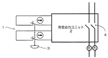
図1に、安全を確保する対象である一の安全コンポーネントで機器を停止させるシステムを構成した一例を示す。ここで安全コンポーネントとは、作業者の安全を確保すべき具体的な動作を受けて、所望の機器への電源供給を遮断する指令を送る要素である。例えば作業者が機器の段取り替えやティーチング、調整のために駆動モータの動作を停止させるための非常停止スイッチや、機器の作業エリアに作業者が入るためにセーフティドアを解放したことを検知するセーフティドアスイッチ、あるいは作業者が危険区域に接近したことを光学的に検知するライトカーテンの出力等が該当する。安全コンポーネント1は、安全リレー装置を構成する安全出力ユニット2と組み合わせて安全回路を構成する。図1に示す安全回路は、常閉のブレーク式の安全コンポーネントスイッチ3を接続している。安全回路が閉じているとき、安全出力ユニット2は正常と判断し、リレー4を閉じて接続機器への電力供給が維持される。一方、作業者やユーザが手動で操作もしくはセンサ等の出力で安全コンポーネントスイッチ3を操作することにより、安全回路が開放されると、安全出力ユニット2は安全ではない状態と判断し、リレー4を解放して接続機器への電力供給を断ち、動作を停止させる。
【0006】
このシステムは冗長性を持たせるため、図1に示すように二重の安全回路を構成しており、安全コンポーネントスイッチ3を操作することで両方の安全回路が開放される。これによって、いずれか一方の安全回路が接点溶着等で不良又は故障となっても、他方の安全回路が機能するので、機械を停止可能である。さらに、自己点検を行うことで、接点溶着等の異常を検出することが可能であり、故障の累積を防止できる。また、このシステムでは異種構造を採用しており、同じ不良が同時に起こることを防止している。
【0007】
【特許文献1】
特開平11−162317号公報
【0008】
【発明が解決しようとする課題】
各安全コンポーネントを接続する入力ユニットは、安全コンポーネントによって安全状態を確認し、安全であることを検出できると安全入力信号を出力する。各入力ユニットで取得された安全入力信号は、マスタユニットに集められ、すべての安全コンポーネントで安全であることが確認されると、安全出力を出力ユニットに出力する。逆に、いずれかの安全コンポーネントで安全が確認できない場合は、安全出力をOFFとする。このように、安全リレーシステムではすべての安全入力のANDとして、安全出力をONとしている。
【0009】
一方、安全コンポーネントの中には、装置の設営やメンテナンス作業等においては安全が確認できない状態で機器を動作させる必要が生じることがある。例えば作業用ロボットのティーチング作業の際には、図2に示すように作業者がロボット37の作業エリアに近接して、ティーチングペンダント38等を用いてティーチング作業を行うために、作業エリアを区画するフェンス39のセーフティドア40を開けると、セーフティドア40に設けられた安全コンポーネントであるドアセンサ41がセーフティドア40の開放を検出してシステムを停止させる。しかしながら、ティーチング作業時には、ロボットの作業位置等を確認する必要があるので実際にロボットを動作させる構成が要求される。
【0010】
このような場合に、安全コンポーネントの検出結果に関わらず機器を動作させるためのイネーブル機能や、安全コンポーネントの安全入力を無視するミュート機能を持たせることができる。しかしながら、これらの機能は安全コンポーネントを無効化するため、作業者の安全を確保できない状態となることから、万一の事故に備えて作業者を保護する機構が必要となる。例えば、作業者が作業中であることを知らずに他の者がセーフティドアを閉めて通常動作を行わせようとすると、再起動が可能であるため作業者に危険が及ぶおそれがある。一方で、保守やメンテナンス、ロボットのティーチング作業等を容易に行うための機能も求められている。
【0011】
本発明は、このような問題点を解決するためになされたものである。本発明の目的は、メンテナンス作業等に適した特定の安全コンポーネントについて無効化させる機能を備えると共に、無効化させる際の条件を設定することで不用意なシステムの動作を許可せず、作業者の安全を確保し得る安全リレーシステムおよび安全リレーの制御方法を提供することにある。
【0012】
【課題を解決するための手段】
上記目的を達成するために、本発明の請求項1に記載される安全リレーシステムは、一以上の安全コンポーネントからの入力状態に基づいて安全か否かを判断し、安全でないと判断した場合に接続機器の内少なくとも危険箇所の動作を直接的または間接的に停止させるためのリレーを制御する安全リレーシステムであって、前記外部接続機器に関する所定の安全コンポーネントについて、その安全状態に関わらず安全入力を取得するマニュアルサスペンションを機能させるためのマニュアルサスペンション入力部と、前記マニュアルサスペンション入力部でマニュアルサスペンションを機能させるために所定の条件が具備されているか否かを確認し、所定の条件が具備された場合のみマニュアルサスペンションを機能させるマニュアルサスペンション動作確認部とを備えることを特徴とする。
【0013】
また、請求項2の安全リレーシステムは、一以上の安全コンポーネントからの入力状態に基づいて安全か否かを判断し、安全でないと判断した場合に接続機器の内少なくとも危険箇所の動作を直接的または間接的に停止させるためのリレーを制御する安全リレーシステムであって、前記外部接続機器に関する所定の安全コンポーネントについて、その安全状態に関わらず安全入力を取得するマニュアルサスペンションを機能させるためのマニュアルサスペンション入力部と、前記外部接続機器の動作を通常よりも安全を高めた安全モードに切り替えるためのモード切替部と、前記モード切替部で前記外部接続機器が安全モードに切り替えられた後、マニュアルサスペンション入力部からマニュアルサスペンションの動作命令が得られているとき、前記所定の安全コンポーネントに代わって安全入力を出力するための手動切替入力部とを備えることを特徴とする。
【0014】
また、請求項3の安全リレーシステムは、所定の動作範囲で動作する外部接続機器の動作範囲を中心とした所定の領域への侵入を所定の安全コンポーネントで監視し、安全コンポーネントの出力によって外部接続機器の動作を制限する安全リレーシステムであって、前記外部接続機器の動作を通常モードよりも動作速度を限定した手動モードに切り替えるためのモード切替部と、所定の領域に作業者が侵入するために所定の安全コンポーネントの安全入力に関わらず安全入力を得るマニュアルサスペンションを機能させるためのマニュアルサスペンション入力部と、前記モード切替部で手動モードに切り替えられた後、マニュアルサスペンション入力部からマニュアルサスペンション入力が得られたとき、前記所定の安全コンポーネントについて安全状態に関わらず安全入力を生じさせるための手動切替入力部とを備えることを特徴とする。
【0015】
さらに、請求項4の安全リレーシステムは、請求項2から3のいずれかに記載の安全リレーシステムであって、前記手動切替入力部が前記所定の安全コンポーネントとOR接続されていることを特徴とする。
【0016】
さらにまた、請求項5の安全リレーシステムは、請求項1から4のいずれかに記載の安全リレーシステムであって、前記安全コンポーネントが、ドアの開閉を検知して侵入を検出するドアスイッチであることを特徴とする。
【0017】
また、請求項6の安全リレーの制御方法は、一以上の安全コンポーネントからの入力状態に基づいて安全か否かを判断し、安全でないと判断した場合に接続機器の内少なくとも危険箇所の動作を直接的または間接的に停止させるための安全リレーの制御方法であって、外部接続機器の動作を通常よりも安全を高めた安全モードに切り替えるステップと、前記外部接続機器に関する所定の安全コンポーネントの安全状態に関わらず安全入力を取得するマニュアルサスペンションを機能させるステップと、安全モードへの切り替えステップと、次いでマニュアルサスペンションステップを経たことを確認し、所定の安全コンポーネントに代わって安全入力を出力するステップとを備えることを特徴とする。
【0018】
【発明の実施の形態】
以下、本発明の実施の形態を図面に基づいて説明する。ただし、以下に示す実施の形態は、本発明の技術思想を具体化するための安全リレーシステムおよび安全リレーの制御方法を例示するものであって、本発明は安全リレーシステムおよび安全リレーの制御方法を以下のものに特定しない。
【0019】
また、本明細書は特許請求の範囲に示される部材を、実施の形態の部材に特定するものでは決してない。特に実施の形態に記載されている構成部品の寸法、材質、形状、その相対的配置等は特に特定的な記載がない限りは、本発明の範囲をそれのみに限定する趣旨ではなく、単なる説明例にすぎない。なお、各図面が示す部材の大きさや位置関係等は、説明を明確にするため誇張していることがある。さらに以下の説明において、同一の名称、符号については同一もしくは同質の部材を示しており、詳細説明を適宜省略する。さらに、本発明を構成する各要素は、複数の要素を同一の部材で構成して一の部材で複数の要素を兼用する態様としてもよいし、逆に一の部材の機能を複数の部材で分担して実現することもできる。
【0020】
なお本明細書においては、「入力側」、「出力側」等の表現は説明のために使用しており、必ずしも入力、出力機能のみを果たすことを意味しない。例えば入力側の端子が出力、あるいは出力側の端子が入力を扱うこともできる。特に、ユニット間に通信機能を設けず、配線パターンのみで認識信号を伝達する場合は、接続端子は接続形態に応じて入力、出力のいずれの機能も果たす。
【0021】
図3に、本発明の一実施の形態に係る安全リレーシステムの構成例を示す。この図は制御システムの安全関連部分を示している。この例においては、2つの安全コンポーネント1として、非常停止スイッチである安全コンポーネントスイッチ3を安全リレーシステムに接続している。非常停止スイッチはそれぞれ直接開路動作機能(強制開離機構)を備えており、かつ接点を二重化しており、各々の接点において安全回路を構成している。安全リレーシステムは、安全コンポーネントからの入力状態に基づいて安全か否かを判断し、安全を確認する。もし安全が確認できない場合は、安全でないと判断し、接続機器の内で危険を及ぼす箇所の動作を停止させる。停止は、リレーを直接制御して開放し電力供給を遮断して停止させる他、コンタクタ等を介して間接的に停止させることもできる。あるいは、電力供給の遮断以外にも、停止命令を接続機器に送り、その命令に基づいて機器の中で危険箇所を能動的に制御しながら停止させてもよい。以下の例においては、リレーによる電力供給の遮断について説明するが、本発明はこの構成に限られず、他の方法による接続機器の停止手段を採用することもできる。なお本明細書において「安全ではない状態」とは、安全コンポーネントが正常に動作して危険領域に入ろうとする人を検出する状態等を指し、一方「異常」とは、安全コンポーネントまたは安全リレー装置等が故障した状態等を指す。安全リレーシステムは、安全リレー装置としてリレー4を備えるマスタユニット5と、リレーを含まない入力増設ユニット6を備える。
【0022】
[マスタユニット5]
マスタユニット5は、安全コンポーネント1を接続するための入力部を備える。さらにマスタユニット5はリレー4を内蔵しており、異常発生等、安全が確認できない状態を検知して接続機器への停止命令によりリレー4の切り替えを行う。リレー4には、電磁リレー、ソリッドステートリレー、強制ガイド機構付きの電磁リレー等が適宜利用できる。リレー接点は二重化されており、いずれかのリレー接点が万一溶着しても他方のリレー接点が開放されるので、確実に接続機器を停止できる。リレー4は、コンタクタを介してモータ等の接続機器の通電を制御する。あるいはコンタクタを介さず直接接続機器に接続することもできる。コンタクタも同様に二重化して、一方のコンタクタ接点が溶着しても他方のコンタクタ接点の開放により接続機器を停止させるよう構成できる。この場合、一方のコンタクタ接点が溶着したままでも他方のコンタクタ接点を開放させることができため、接続機器の停止後に始動スイッチをONしても再起動できず、バックチェック機能を実現できる。
【0023】
なお、マスタユニット5は安全コンポーネントを接続する入力部を省略して、入力増設ユニット6側に安全コンポーネントを接続する構成としてもよい。またマスタユニット5はリレーを内蔵するのでなく、外付けのリレーを制御するように構成してもよい。
【0024】
[入力増設ユニット6]
入力増設ユニット6は、同じく安全コンポーネントを接続するための入力部を備える。この入力増設ユニット6はマスタユニット5と異なりリレーを内蔵しないので、回路を簡単に構成して安価にすることができる。リレーは機械的動作部分を含み、駆動のための制御回路等が必要で、また大電流の通電に耐えうる接点や繰り返し開閉動作しても機能する耐久性も要求され、一般に複雑で高価となる。このため、安全コンポーネント1を接続するユニット毎にリレー4を設ける構成では、入力数に応じてコストも高くなる。これに対して本発明の実施の形態に係る図3の構成では、リレーを省略した入力増設ユニット6を増設可能とすることで、入力数に応じて増設するユニットを簡単にして、コストを安価にすることができる。さらにリレーを含まない入力増設ユニット6においては、リレーに通電する大電流も流れないため、大電流用の配線接続が不要であり、より安価で接続の容易な信号線の接続で足りる。しかもコネクタ式にできるので、連結も簡単かつ容易に行える。さらに配線数も少なくなるので、省スペース化にも寄与する。
【0025】
各ユニットに接続された安全コンポーネント1の安全コンポーネントスイッチ3は、常閉(NC)接点である。正常時は安全回路はそれぞれ閉路されて通電しており、ユニット側はこれを安全情報としてモニタし、リレー4を閉じてモータ等の接続機器に通電する。一方、非常時に非常停止スイッチを押下すると、対応する2つの安全コンポーネントスイッチ3の常閉接点がそれぞれブレークされて安全回路が開放されるので、ユニット側は安全情報が失われたことを検知し、リレー4を開いて接続機器への通電を遮断する。この状態になると、接続機器を動作させることができない。
【0026】
この安全リレーシステムは、マスタユニット5もしくは入力増設ユニット6に接続された安全コンポーネント1の安全コンポーネントスイッチ3のいずれかが操作されると、該当する安全回路が開放されるので安全が確認できない状態を検出できる。しかも、各安全回路は独立しているので、いずれかの安全コンポーネントスイッチ3に不良または故障が生じても検出することができる。マスタユニット5による安全コンポーネントスイッチ3の自己点検は、例えば所定の周期毎にテスト信号を送出して開閉のチェックを行う。この構成によって、リレー接点の二重化、コンタクタ接点のバックチェック機能、安全コンポーネントスイッチの自己点検が実現され、EN954−1に基づくカテゴリ4等の安全基準に対応可能な安全リレーシステムが実現可能となる。カテゴリ4では、単一故障に対する安全システムの設計として「単一故障により安全機能が失われないこと、かつ、単一故障を安全システムの次回の要求時またはその前に検出されること。もしそれが不可能な場合には、故障の蓄積により安全機能が失われないこと」が、要求されている。
【0027】
また安全コンポーネントは、非常停止スイッチのみに限られず、各種センサ等、作業者の安全を確保すべき具体的な動作を確認する部材が使用できる。例えば、機器の作業エリアと区画するフェンスに作業者の出入りのために設けられたセーフティドアの開閉を検知するリミットスイッチや、作業者が機器に接近したことを光学的に検知するライトカーテンやエリアセンサ等が利用できる。これら安全コンポーネントによって安全が確認されると、安全入力がマスタユニットに向けて出力され、マスタユニットはすべての安全コンポーネントで安全が確認されると、すなわちすべての安全入力がONとなると、安全出力をONとして機器の動作を許可する。
【0028】
[入力増設ユニット6の増設]
図3では2つの安全コンポーネントを接続する例を示したが、さらに安全コンポーネントを追加して3つの安全コンポーネントを入力するには、図4に示すように入力増設ユニット6Aに入力増設ユニット6Bを追加する。入力増設ユニット6Bは上述した入力増設ユニット6Aと同様のものが利用できる。また入力増設ユニット6Bに接続された安全コンポーネント1の安全コンポーネントスイッチ3の操作も上記と同様で、非常停止スイッチ等の動作によってマスタユニット5のリレー4が操作される。これによって、新たにシステムを設計し直したり回路を組み替えることなく、入力増設ユニット6を追加することで簡単に安全コンポーネントの増設に対応できる。また、各入力増設ユニット6の出力をマスタユニット5でまとめることができるので、ユニット間の配線も簡素化でき、この点においても省配線に寄与する。
【0029】
[コネクタ]
ユニット間の接続には、コネクタを使用する。コネクタは複数の接続端子を電気的に接続する。入力増設ユニット6は、入力側端子群と出力側端子群を備えており、入力側端子群は他の入力増設ユニット6や入力エンドユニット12と、出力側端子群は他の入力増設ユニット6やマスタユニット5とそれぞれ接続する。一例として、入力増設ユニット6をマスタユニット5に接続する様子を図5に示す。図5では相互にコネクタ7を挿入し、フックで係止してユニット同士を連結している。上述のように入力増設ユニット6にはリレーを含まないので、リレーを流れる大電流用の配線が不要となり、簡易なコネクタ式の接続で足りる。各ユニットには、接続用のコネクタ7が側面の略中央に設けられており、対向する接合面で一方が雄型7A、他方が雌型7Bとなるように対応する位置にそれぞれのコネクタ7が配置される。またユニットの接合面において、一方の面の端部付近で両側に一対の係止用のフック8と、フックに対応する対抗面の位置にこのフックを係止するための係止溝9がそれぞれ設けられる。マスタユニット5は入力増設ユニット6を接合する一面のみにこれらコネクタ7、フック8あるいは係止溝9を設けているが、入力増設ユニット6は両面にユニットを接続できるよう、両面にこれらのコネクタ7やフック8等を設けている。この図はマスタユニット5と入力増設ユニット6の接続例を示しているが、入力増設ユニット6同士や入力増設ユニット6と入力エンドユニット12との接続も同様にして実現できる。
【0030】
コネクタは、入力側端子群と出力側端子群とを個別に構成して、各ユニット間で入力側端子群と出力側端子群のコネクタ同士を直接係合する方式とする他、入力側端子群と出力側端子群を一体にしたコネクタとすることもできる。例えば、図6においては、接続用ボード10に各ユニットを装着する形態としている。図6の例では、各ユニットの一面に入力側端子群と出力側端子群を一体にした雄型コネクタが設けられ、接続用ボード10にはこの雄型コネクタに係合可能な雌型コネクタ7Cが設けられる。雌型コネクタ7Cは一定間隔で接続ボード10上に複数設けられ、各ユニットを装着した状態でユニットが略一直線に並ぶよう雌型コネクタ7Cの間隔が設定される。
【0031】
これら雄型、雌型コネクタの雄型、雌型はユニットとボードで逆にしてもよく、またコネクタの形状は、複数のピンを配置するタイプやベローズ状に面に接点を配置するタイプ等が適宜利用できる。またコネクタの位置も、略中央に限られず、偏心位置や端部等所望の位置に設定できる。またコネクタ自体にフック等の係止部材を設け、電気的接続と機械的連結を兼用する構成としてもよい。あるいはユニット同士の接続は、ユニットに設けられたコネクタ同士を直接係合する方式の他、別部材のコネクタやコード等を介して接続する形態とすることもできる。
【0032】
[出力側の増設]
以上は、安全リレーシステムの入力側を追加する構成について説明した。次に、安全リレーシステムの出力側を追加する構成について説明する。安全リレーシステムにおいて、出力側を追加したいことがある。安全でない状態または異常検出時に停止させたい機器を増やしたい場合は、この機器への電力供給を断つためのリレー等をマスタユニットの出力側に付加する必要がある。そこで出力増設ユニット16をマスタユニットに連結する。以上のように入力増設ユニット6は安全コンポーネントを接続しており、安全コンポーネントから安全入力を得る。一方、出力増設ユニット16は安全リレー出力部58を接続しており、安全出力として停止信号に基づきリレーを開閉させる。
【0033】
[ステータス安全確認情報]
さらに出力増設ユニット16は、各ユニット毎に安全確認のための情報を検知し続けてマスタユニット側に送出し、マスタユニット側で各出力増設ユニット16の安全確認情報を常時モニタすることで安全リレーを安全側に動作させ続けることができる。すなわち、安全が確認できる状態で接続機器を動作させ、安全が確認できなくなると動作を停止させるように制御する。安全確認のための情報は、好ましくはダイナミックな信号とする。出力増設ユニット16は安全確認のための情報としてステータス安全確認情報をマスタユニット側に送出する。ステータス安全確認情報は、出力増設ユニット16が内蔵する自己診断回路にてユニットの動作が正常であること、あるいは異常や故障が無いことを確認する信号であり、出力増設ユニット16自身のエラー情報等を含むこともできる。この確認は、停止信号のON/OFFと無関係に行われる。出力増設ユニット16はステータス安全確認情報を含む安全確認のための各種の安全確認情報を出力する安全確認情報出力部(図示せず)を備える。
【0034】
[安全情報ライン42]
図7に、本発明の一実施の形態に係る安全リレーシステムの接続状態を示すブロック図を示す。この図に示す安全リレーシステムは、電源ユニット30を一方に接続したマスタユニット5と、マスタユニット5の他方に接続された複数の入力増設ユニット6および出力増設ユニット16と、その端面に接続されたエンドユニット12とを備える。図の例ではマスタユニット5に電源ユニット30を接続すると共に、入力増設ユニット6と出力増設ユニット16を交互に2台ずつ接続し、端面にエンドユニット12を接続している。各ユニットは、コネクタを介して互いに隣接するように直列に接続される。安全入力を伝達する安全情報ライン42は、安全入力用ライン43と安全出力用ライン44の二つで構成される。安全入力用ライン43には入力増設ユニット6の安全制御部45が、安全出力用ライン44には出力増設ユニット16の安全制御部46がそれぞれ接続される。
【0035】
[安全入力用ライン43]
安全入力用ライン43は、入力系の安全回路信号である安全入力を伝送するラインであり、安全性を高めるため2系統の信号を持つよう二重化されている。安全入力の信号は、入力系安全制御部信号である。安全入力用ライン43は、マスタユニット5からエンドユニット12まで各ユニットを介してストレートにスルー接続されるスルーラインと、エンドユニット12からリターンするリターンラインとを備える。図においては、安全入力用ライン43はマスタユニット5のマスタユニット安全制御部47Aにシリアルで接続されており、安全入力用ライン43のリターンラインは、入力増設ユニット6の安全制御部46同士を接続する一方、出力増設ユニット16ではスルーとされる。これによって、入力増設ユニット6は安全入力用ライン43で接続された入力増設ユニット6やエンドユニット12からの信号を認識して動作する。すなわち、前段から伝達される安全入力もしくはエンドユニット12からの信号と、自身に接続された安全コンポーネントの安全状態を示す安全入力とに基づいて新たな安全入力とし、次段に伝達する。例えば、前段の安全入力と自身の安全入力の論理積(AND)を新たな安全入力とすることで、すべての入力増設ユニット6に接続された安全コンポーネントで安全が確認されるとき、マスタユニット5で安全入力が得られ、これに基づいて安全出力をONとすることができる。安全情報をユニット毎に順次確認していく構成とすることで、バスの本数を削減でき、安全制御部45、46を簡略化できる。また接続可能なユニット数がバスの本数によって制限されず、多数のユニットを増設することが可能となる。
【0036】
ただ、図示しないが安全入力用ラインをパラレルラインとし、ユニット間をシフト接続させるよう構成することもできる。例えば、マスタユニットからエンドユニットまでストレートに接続する一方、リターンラインを、入力増設ユニットを一介す毎に一ずつシフトさせるよう構成することで、入力増設ユニットの接続台数分シフトしてマスタユニットに信号が返されるため、マスタユニット側で安全入力の検出される端子番号をチェックすることで入力増設ユニットの接続台数を検出できる。また、各入力増設ユニットに接続された安全コンポーネントの出力を同様にシフトさせながらマスタユニットに伝達することで、いずれの安全コンポーネントで安全確認が得られないかを検知することもできる。
【0037】
[安全出力用ライン44]
安全出力用ライン44は、出力系のモニタ回路信号である安全出力を伝送するラインであり、安全入力用ライン43と同様に2系統の信号を持つよう二重化されている。また安全出力用ライン44も、マスタユニット5からエンドユニット12までストレートにスルー接続されるスルーラインと、エンドユニット12からリターンするリターンラインとを備え、シリアルラインで接続される。図においては、安全出力用ライン44はマスタユニット5のマスタユニット安全制御部47Bにシリアルで接続されており、安全出力用ライン44のリターンラインは、出力増設ユニット16の安全制御部46同士を接続する一方、入力増設ユニット6ではスルーとされる。これによって、出力増設ユニット16は安全出力用ライン44で接続された出力増設ユニット16やエンドユニット12からの安全確認情報を認識して動作する。すなわち、前段から伝達される安全出力もしくはエンドユニット12からの信号と、自身の出力増設ユニット16の安全確認情報とに基づいて新たな安全出力とし、次段の出力増設ユニット16の安全制御部46に出力する。これによって、自身より前段の出力増設ユニット16が正常に動作していることを確認すると共に、自身が正常に動作していることを次段の出力増設ユニット16もしくはマスタユニット5に伝達する。
【0038】
上記の安全情報ライン42は、図7において実線矢印で示される。さらに、図7に示す回路は安全信号に関するラインとして、安全情報ライン42以外に一点鎖線で示すFSD出力ライン48、二点差線で示す同期信号ライン49を備える。FSD(Final Switching Device)50は、ライトカーテンなどの安全センサからの出力(OSSD:Output Signal Switching Device)と、外部接続機器を直接的に停止させる装置(MPCE:Machine Primary Control Equipment)との間に配置される。マスタユニット5は入力増設ユニット6などを介して集められた安全入力に基づき、OSSDの出力状態に応じてMPCEに対し停止信号をFSD出力ライン48を介して各出力増設ユニット16から出力する。出力増設ユニット16は停止信号に基づいてFSD出力を制御する。またFSD出力ライン48を介して入力増設ユニット6もモニタすることもできる。FSD出力ライン48も安全のため2系統が用意される。
【0039】
また同期信号部51は、シリアルで転送される信号の同期をとる同期信号をマスタユニット5から各ユニットに対し同期信号ライン49を介して送出する。同期信号によって機器の動作を行うタイミングが決定される。これらのFSD出力ライン48、および同期信号ライン49は上記安全情報ライン42のようにリターンラインを備えず、マスタユニット5からエンドユニット12に向かって停止信号、同期信号をそれぞれ送出する。
【0040】
上記の構成によって、ユニット間で接続するコネクタの共通化、ピン数の削減が図られる。図7の例では、マスタユニット5とエンドユニット12の間で入力増設ユニット6と出力増設ユニット16を交互に接続しているが、この例に限られず、入力増設ユニット6と出力増設ユニット16はマスタユニット5とエンドユニット12の間であれば任意の位置で接続できる。例えばマスタユニットに入力用のコネクタと出力用のコネクタを設け、入力用のコネクタに入力増設ユニットを、出力用のコネクタに出力増設ユニットを接続し、それぞれの端面にエンドユニットを接続する構成では、接続状態や配置の制約を受ける。安全コンポーネントや外部接続機器の数によってユニット数が異なるので、配置スペースによってはうまく配置できないこともあり得る。上記本発明の実施の形態によれば、入力増設ユニット6、出力増設ユニット16を同一のライン上に混在できるので、配置上の制約が低減され柔軟なレイアウトが可能となる。さらに、レイアウトの柔軟さはスペースの効率的な利用を可能とし、システムの小型化にも寄与し得る。
【0041】
[非安全情報ライン52]
一方、図7に示す回路は安全情報ライン42以外に非安全情報に関する非安全情報を送出する非安全情報ライン52を備える。非安全情報ライン52は図7において鎖線で示す。非安全情報ライン52は、安全リレーシステムの情報系信号ラインであり、例えばRS485の通信ライン等を使用できる。
【0042】
[非安全情報]
非安全情報には、例えばマスタユニット5や入力増設ユニット6に接続される安全コンポーネントのON/OFF情報、各ユニットのエラー状態とエラー情報、マスタユニット5や出力増設ユニット16の出力情報、出力増設ユニット16のOFFディレー等の設定に関する実際の出力状態に関する情報、各入力増設ユニット6の手動モード・メンテナンスモード・ミュート状態で安全コンポーネントの無効化した状態等における実際の入力状態に関する情報、DIPスイッチの情報等各ユニットの設定情報、各ユニット毎に付与されるユニットID番号に関するID情報やステータス情報等がある。ステータス情報には、停止信号のON/OFFやユニットのエラー情報などがある。なお非安全情報とは、安全情報に関する情報であるが、規格上特別な仕様が要求される安全情報に該当しない情報であるという意味で、本明細書において非安全情報と呼ぶ。よって、非安全情報は、その名称に拘わらず安全情報に関する情報や安全情報そのものを含めることもできる。ただし、非安全情報を安全情報に含めることはできない。
【0043】
ユニットにID番号を付与する方法は、既知の方法や将来開発される方法が利用できる。例えば、ID付与のための信号線を追加して、信号線から接続順にユニットに対しID番号を付与すると共に、ID番号を次段のユニットに伝達し、増加させたID番号を付与すると共にさらに次段のユニットに伝達するというユニットを経る毎にID番号を増加させる方式が利用できる。
【0044】
非安全情報ライン52は、安全情報を扱う安全情報ライン42と個別に設けられ、安全情報と非安全情報を分離させている。安全情報を非安全情報にフィードバックすることはあっても、非安全情報を安全情報にフィードバックすることはない。これによって安全情報は完全に分離され、非安全情報から影響を受けることなく独立して扱われる。いいかえると、非安全情報を扱う回路に何らかの異常が生じても、安全情報を扱う回路に影響を与えることがなく、システムの安全性が維持される。この結果、安全情報を扱う回路についてのみ、必要な二重化や自己チェック機能の付加などを行うことでIEC61508−2 7.4.2.3等に定められる安全基準をクリアでき、一方で非安全情報を扱う非安全系回路にはこれらの仕様を具備する必要がないので、非安全系回路を比較的簡素に構成できる。さらに、安全情報と非安全情報を同時に扱う構成では、安全情報を扱う限り厳格な仕様が要求されるが、安全情報と非安全情報を分離することにより、安全情報を扱う回路のみが要求される仕様を満たせば足りるので、システム構成を簡素化できる。このことは、システムの設計変更に際しても柔軟に対応でき、安全系回路の再設計の必要性をなくして設計を容易にできる。加えて、非安全情報を付加することで、トラブルが発生した際の復旧を容易にできるなど、システム運用上の使い勝手を改善できる。例えば、安全確認ができない箇所やトラブル発生箇所の特定や異常内容の表示、復旧のための手順の案内などを行える。
【0045】
従来の安全リレーシステムに使用されるリレーユニットでは、安全基準に適合するための仕様の制約により、安全情報として装置のON/OFF情報のみを出力している。言い換えると、全体として安全が確認できるか否かを判断するのみであり、個別の安全コンポーネントの入力状態を確認することはできなかった。これでは、安全は確保できるとしても、安全が確認できない場所の特定やその原因を検知することはできなかった。そのため、原因の特定を自動的に行えず、システムの復旧作業が極めて困難であるという問題があった。トラブル発生時時に各個の安全コンポーネントの入力状態が把握できないと、原因を特定できずシステムを復帰できない。またシステムの保守やメンテナンスを考慮すると、各安全コンポーネントの状態を確認することが望ましい。この情報をモニタすることにより保守やメンテナンスを効率的に行い、時間を短縮できる。そこで、安全情報と非安全情報を分離することで、非安全情報を複雑な回路を用いないで構成することが可能となる。一般に機械、ロボットなどを含むシステムは非常停止ボタン、安全ドア、ライトカーテンなど複数の安全コンポーネントにより構成される。非安全情報として各安全コンポーネントの入力状態をモニタすることで、システムの安全が確認できない状態となった時、どの安全コンポーネントが原因で安全が確認できないかのを特定する情報を出力する。例えば各入力増設ユニット6等に接続された安全コンポーネントのON/OFF情報、ユニットのエラー情報など、各ユニットの状態を非安全制御部54でマスタユニット5に通知する。マスタユニット5はマスタユニット非安全制御部53で非安全情報を集め、非安全情報インターフェース55から外部に出力する。この信号を外部のPLC等に入力して表示させ、トラブル時などの復帰に役立てることができる。非安全情報は安全/非安全の判別、すなわち安全確保に関しては直接関係するものではなく、むしろシステム復帰に関して有用な情報であり、この情報を活用してより迅速に復旧を行える。
【0046】
[共通ライン]
また、安全情報ライン42は図7のように安全入力用ライン43と安全出力用ライン44に区別する構成の他、図8に示すように共通のラインとすることもできる。これによって、入力系安全制御部信号と出力系モニタ回路信号を同じバスで扱うことができる。安全入力用と安全出力用とを共通とする安全情報ライン42は、マスタユニット5よりエンドユニット12までストレートで繋がるスルーラインと、エンドユニット12からリターンするリターンラインを備える。図8の例では、安全情報ライン42はマスタユニット5のマスタユニット安全制御部47からエンドユニット12までスルーラインで接続され、エンドユニット12で反転してリターンライン上に出力増設ユニット16および入力増設ユニット6の安全制御部45がそれぞれ接続され、これらの安全制御部45とマスタユニット5のマスタユニット安全制御部47とが安全情報をやりとりする。
【0047】
入力増設ユニット6及び出力増設ユニット16は、リターンライン上で前段に接続されたユニットもしくはエンドユニット12からの信号を認識して動作する。入力増設ユニット6は自身の入力増設ユニット6に接続される安全コンポーネントからの安全入力と、前段から伝達される安全入力とを安全制御部45で安全入力とし、次段の入力増設ユニット6に順次送出してマスタユニット5に伝達する。出力増設ユニット16は安全制御部46で、自身の正常状態を確認する安全確認情報と、リターンライン上で前段に接続された出力増設ユニット16の安全確認情報とに基づいて安全確認情報を生成し、次段の出力増設ユニット16に伝達する。出力増設ユニット16の安全制御部46は、リターンライン上を伝達される信号から、前段の出力増設ユニット16またはエンドユニット12から伝達される安全確認情報を抽出して、安全確認情報をさらに伝達する。いいかえると、入力増設ユニット6に関する安全入力はスルーする。一方、入力増設ユニット6の安全制御部45は前段の入力増設ユニット6もしくはエンドユニット12から伝達される安全入力信号を抽出して、安全入力を次段の入力増設ユニット6に伝達する。このように、安全入力用と安全出力用とを共通とする安全情報ライン42では、各々の安全制御部45,46で必要な信号を選別し、必要でない信号はそのまま伝達することで、同一のライン上に様々な信号を混在させることができる。図8においても、安全情報ライン42で伝送される安全入力や安全確認情報は図7と同様のものが適用でき、さらにFSD出力ライン48や同期信号ライン49も同じ構成とできる。
【0048】
上記の構成では、各ユニットの非安全情報を非安全情報ライン52を介して順次伝達し、最終的にマスタユニット5に至るように構成している。非安全情報を受けたマスタユニット5は、非安全情報に基づいて表示や外部への出力を行う非安全情報出力部56を備える。非安全情報出力部56は、非安全情報をそのまま、あるいは加工して外部に表示させるモニタや外部に出力するインターフェースなどが利用できる。例えば、モニタ上に各安全コンポーネントの安全状態を表示させ、エラーの発生や外部接続機器のON/OFFを表示させたり、安全が確認できない箇所を点滅表示させたり、PLCなどの機器にこれらの情報を送出する。図9の例では、非安全情報出力部56としてモニタ表示のための非安全情報表示部57と、外部入出力端子等の非安全情報インターフェース55を備えている。ただ、非安全情報出力部56はマスタユニット5に設ける例に限られず、これに代わって、あるいはこれに加えて、ユニット側に設けることもできる。複数の非安全情報出力部を備えることで、非安全情報出力部同士で相互に非安全情報をやりとりすることも可能となる。ユニット側に非安全情報出力部を設ける場合は、このユニットの非安全情報出力部で非安全情報を利用できるので、他のユニットやマスタユニットに非安全情報を伝えるためのバスを不要とできる。
【0049】
次に、図9に基づいて安全情報から分離された非安全情報の扱いを説明する。図9においては、上記図8で説明した安全入力用と安全出力用とを共通とする安全情報ライン42での構成を採用しており、マスタユニット5と出力増設ユニット16、入力増設ユニット6を接続する部分を示している。この例では、マスタユニット5も安全コンポーネント1および安全リレー出力部58をマスタユニット安全制御部47に接続している。このマスタユニット5は、入力増設ユニット6および出力増設ユニット16として機能する。ただ、これらの部材のいずれかもしくは両方をマスタユニットに設けない構成としてもよいことはいうまでもない。
【0050】
安全情報は、図9で実線の矢印で示す安全情報ライン42を通じて、マスタユニット5のマスタユニット安全制御部47からエンドユニット(図9では図示せず)にスルーライン(図9では一点鎖線)で送出される。安全情報ライン42はエンドユニットで逆向きのリターンラインとなり、エンドユニットから各ユニットの安全制御部45を通じてマスタユニット安全制御部47に返される。このとき、安全入力については、入力増設ユニット6の安全制御部45に接続された安全コンポーネントから取得される。各安全制御部45は前段のユニットから送出される安全入力と、自身に接続された安全コンポーネントの安全入力に基づき新たな安全入力を生成し、次段の入力増設ユニット6に送出する。このようにして安全入力はマスタユニット5から安全情報ライン42を通じて順次入力増設ユニット6に送出され、最終的にマスタユニット安全制御部47に戻される。例えば、すべての安全入力のANDをとることによって、いずれかの安全コンポーネントで安全入力が得られなかった場合、すなわち安全が確認できない場合は、安全出力をONとせずリレーを開放して所定の外部接続機器の動作を停止する。
【0051】
一方、安全情報ライン42は安全出力も扱い、具体的に外部接続機器の動作を制御するリレーを安全リレー出力部58で開閉させる。安全リレー出力部58は安全リレーを直接あるいはコンタクタなどを介して開閉させる。安全リレー出力部58はこのようなリレーやコンタクタなどを内蔵もしくは接続している。マスタユニット5のマスタユニット安全制御部47は、安全入力に基づいて安全出力を出力し、個々の外部接続機器の動作をON/OFFさせるために安全リレー出力部58に安全出力を送出する。各出力増設ユニット16は、安全制御部46に安全リレー出力部58を接続している。
【0052】
図10は、図9の構成を実現するための一例として、安全制御部45、46をAND回路で構成した状態を示す。この図に示す安全制御部45、46は、安全情報ライン42を介して前段のユニットから送出される信号と、ユニット自身の信号とのANDを新たな出力として次段に送出する。例えば、入力増設ユニット6は、自身の安全コンポーネント1の出力と前段の入力増設ユニットからの出力とのANDを新たな安全入力として次段に送出する。これによって、入力増設ユニットに接続されたいずれか一の安全コンポーネント1でも安全が確認できない場合には安全入力が得られず、安全出力をOFFとして該当する外部接続機器の動作を停止させる。また、出力増設ユニット16は、安全制御部46で自身のユニットの安全状態を確認する安全確認情報出力部23と前段の出力増設ユニットの出力とのANDをとることによって、いずれかの出力増設ユニットで安全確認が得られない場合に、同様に安全出力をOFFとして該当する外部接続機器の動作を停止させる。例えば前段の出力増設ユニットのエラー信号と自身のエラー信号とのANDをとることで、すべての出力増設ユニット16で正常動作が確認されない限り安全出力が得られず、これによって安全が確保される。
【0053】
以上のような安全情報に対して、安全情報に関するより詳細な情報である非安全情報を、安全情報と個別に伝達する。図9の例では、安全情報ライン42と個別の信号線である非安全情報ライン52で非安全情報を伝達する。非安全情報ライン52は、マスタユニット5のマスタユニット非安全制御部53からエンドユニットまで接続され、このライン上に入力増設ユニット6および出力増設ユニット16の非安全制御部54が通信可能に接続されている。各非安全制御部54は、非安全情報出力部56として、非安全情報表示部57と、非安全情報インターフェース55を備える。非安全情報表示部57は、非安全情報を表示させてユーザに安全情報に関する詳細情報を視覚的に知らせる。表示方法は、テキストや画像、動画の他、音声などを適宜組み合わせることができる。これによって、安全確認ができない事態が発生した際に、その場所や原因を表示させユーザに告知することができる。
【0054】
また、非安全情報インターフェース55は、非安全情報に関するI/Oであり、外部機器に非安全情報を出力し、また外部機器から必要な情報や演算結果を得て、さらに加工、洗練された非安全情報を取得して非安全情報表示部57に表示させたり、非安全制御部54に送出して他のユニットにデータを送付することもできる。図9の例では、マスタユニット5、入力増設ユニット6、出力増設ユニット16のすべてがこれら非安全情報表示部57と非安全情報インターフェース55を備えている。ただ、いずれか一方のみを備えるユニットや、他の非安全情報出力部を備えるユニットを混在させてもよい。
【0055】
また非安全制御部54は、安全制御部45,46から安全情報を得て、安全状態をモニタし非安全情報表示部57に安全情報自体を表示させる。ただし、非安全制御部54で得た情報を安全制御部45,46に送ることはしない。これによって、安全情報は非安全情報によって影響を受けることがない。言い換えると、仮に非安全情報に関する回路で問題が生じても、これによって安全系の回路が影響されず、安全システムの信頼性が保たれる。このため、安全システムに要求される仕様に適合させつつ、単なる安全情報よりも詳細な非安全情報に関する回路を安全リレーシステムに付加することができ、しかも付加した非安全系の回路については安全情報に関して影響を与えないため、安全回路に要求される仕様を満たす必要はない。このため、比較的自由な設計が可能となり、高度な情報表示等を行える安全システムを実現できる。また、付加回路の設計は安全回路と独立であるため、設計変更も比較的容易に行えるというメリットもある。
【0056】
[定格表記]
また、エンドユニットの側面には、定格標記部を設けることができる。例えばCEマーキングやEMCサービスなどの認証を受けた機器は認証機関のマークや消費電力など所定の標記が義務付けられることがある。一般には、装置のケースに定格標記のシールを貼付したり、印刷、マーキングを行う等の方法が採用される。しかしながら、このような規格によれば装置外部の使用者から見える部分に所定の大きさの標記を設けることが求められており、標記スペースの確保やその位置によって装置の小型化の妨げとなることがある。そこで、上記の安全リレーシステムではエンドユニットの側面部分に定格標記部を設けることで、このスペースを用いて必要な標記を行うことができる。特にエンドユニットは必ず端面に接続されるので、中間に接続されるユニットのように増設されて面が隠れることなく、接続面と反対の面には空きスペースが得られる。そこでこのスペースを利用して標記を行うことで、他のユニットのスペースを犠牲にすることなく必要な標記を果たすことができる。複数のユニットを連結する構成において、端面に固定されるエンドユニットは装置の一部をなすので、装置に直接的に表示を付した状態とでき、標記義務を果たせる。この構成によって他のユニットに定格表記が不要となるので、各ユニットの定格表記スペースが削減でき、ユニットの小型化に貢献し得る。またエンドユニットの機能を入力増設ユニットや出力増設ユニットに内蔵する場合でも、同様にエンドユニット内蔵型増設ユニットの側面に定格標記部を設けることができる。
【0057】
[セーフティコンディション]
次に図11に、システムの保守、メンテナンス、ロボットのティーチング時などに適した安全機能の手動休止に対応したシステムの一例を示す。この図に示す安全リレーシステムは、増設入力ユニット6Xの安全制御部45Xに、安全コンポーネント1Xと並列に手動切替入力部60を備える。手動切替入力部60は、モード切替部61とマニュアルサスペンション入力部62を接続している。
【0058】
[モード切替部61]
モード切替部61は、外部接続機器の動作を通常モードと手動モードに切り替えるための切り替えスイッチである。手動モードとは、通常動作時よりもロボットの動作速度を遅くする、あるいは動作内容を限定する等の制限を加えた動作モードであり、このモードに切り替えることで作業者の安全を確保する。作業者は、メンテナンス作業などの開始時に、モード切替部61を操作して動作モードを手動モードに切り替え、セーフティコンディション状態に設定する。
【0059】
[マニュアルサスペンション入力部62]
またマニュアルサスペンション入力部62は、モード切替部61で手動モードにあるとき、関連する安全コンポーネント1Xを無効化するマニュアルサスペンション(安全機能の手動休止)の開始を指示するための部材である。マニュアルサスペンションが安全リレーシステムに指示されると、対応する安全コンポーネント1Xが無効化されるので、この安全コンポーネントの安全入力に関わらず外部接続機器であるロボットの動作が可能となる。マニュアルサスペンション入力部62は、例えば図13に示すように増設入力ユニット6Xにスイッチとして設ける。
【0060】
[手動切替入力部60]
手動切替入力部60は、マニュアルサスペンションを機能させるための所定の条件が具備されているか否かを確認するマニュアルサスペンション動作確認部の一形態として、モード切替部61とマニュアルサスペンション入力部62の入力に基づいて、安全コンポーネント1Xの無効化を行う。具体的には、まずモード切替部61で手動モードに切り替えられている状態で、マニュアルサスペンション入力部62からマニュアルサスペンションが入力されていることが確認されると、安全コンポーネント1Xに関わらず安全入力を出力させる。逆に、上記の順序が確認できない場合は、マニュアルサスペンションは機能しない。例えば先にマニュアルサスペンション入力部62が操作された後にモード切替部61が手動モードに切り替えられても、手動切替入力部60は機能しない。手動切替入力部60は、所定の手順を踏んで操作されていることを確認することで、正しくマニュアルサスペンションが要求されていると判断し、手順に従っていない場合はマニュアルサスペンションを許可しない。手動切替入力部60の動作は、モード切替部61とマニュアルサスペンション入力部62の動作を監視して、マニュアルサスペンション入力部62のONと同時に自動で安全入力を安全制御部45Xに出力する構成の他、操作者が手動で手動切替入力部60の操作ボタンなどを操作すると、安全入力が出力される構成としてもよい。これによって、操作者が誤ってマニュアルサスペンション入力部62あるいは手動切替入力部60を操作しても、誤動作であると判断されてマニュアルサスペンションが働かず、安全コンポーネント1Xが無効化されないので作業者の安全が確保される。また、手動切替入力部60は、所定の手順に従わずマニュアルサスペンション入力部62が操作された場合に異常と判断してシステムを停止する命令を発することもできる。さらに、マニュアルサスペンションを機能させる際の条件を他の条件に設定することも可能で、例えばさらに別のボタンを設けて3段階以上の操作を経た場合にONさせたり、あるいはモード切替部61の操作後、所定時間以内にマニュアルサスペンション入力部62を操作しなければマニュアルサスペンション機能をONできないといった条件を設定することも可能である。
【0061】
具体的な構成としては、例えば図11に示すように手動切替入力部60と安全コンポーネント1Xとを並列にOR回路に入力し、手動切替入力部60からON信号を入力することで安全制御部45Xは安全入力を得ることができ、安全コンポーネント1Xで安全が確認できなくなっても安全入力が得られるため、ロボットなどの外部接続機器が動作を継続することができる。なお図11の例では、手動切替入力部60を安全制御部45Xと別体としているが、安全制御部に手動切替入力部の機能を持たせることもできる。
【0062】
次に、作業者がメンテナンス作業等でロボットの作業区域に入るためドアスイッチの安全コンポーネント1Xを無効化する手順を図12のタイミングチャートに基づいて説明する。まず、安全コンポーネント1Xの安全入力がONで安全出力が得られている状態を想定する。このとき、他の安全コンポーネント1はすべてONであると仮定する。この状態において、(1)でモード切替部61を操作して手動モードに切り替えると、ロボットは(A)の区間で示す自動モードから(B)の手動モードの動作に切り替えられ、所定の速度以上で動作しないセーフティコンディションとなる。次に(2)でマニュアルサスペンション入力部62を操作してONとすると、ロボット側にマニュアルサスペンションに移行することが指示される。これによって(3)で手動切替入力部60は正しくマニュアルサスペンションが要求されたと判断してON信号を出力可能となる。手動切替入力部60によってマニュアルサスペンション機能が働くと、ドアスイッチの安全コンポーネント1Xは無効化され、(4)で作業者がセーフティドアを開けてロボットの作業区域に侵入しても安全出力はONのまま維持される。作業者はメンテナンス作業終了後、セーフティドアを閉めて、手動切替入力部60または/及びマニュアルサスペンション入力部62をOFFとすると、マニュアルサスペンションが解除される。その後、(5)でモード切替部61を自動モードに戻すと、ロボットは(C)の区間で示すように自動モードで動作し、例えば(6)で安全コンポーネント1XがOFFとなると動作を停止する。
【0063】
また、上記の手順においても、他の安全コンポーネント1で安全が確認できない事態が発生したときは、安全コンポーネント1Xに関わらず直ちに安全出力がOFFとなって安全リレーが開放され、速やかに該当する外部接続機器の運転が停止される。例えば非常停止ボタンが押された場合にはマニュアルサスペンションに関わらず停止信号が出力されるので安全が確保される。
【0064】
上記のシーケンスを、安全制御部45Xの論理として表1に示す。この表において、入力Aに対応する安全コンポーネント1Xには例えばドアスイッチが利用でき、表1においてドアスイッチがONのとき○、OFFのとき×として表示する。同様に入力Bに対応するモード切替部61は、例えば通常モードと安全モードを切り替える場合は通常モードを×、安全モードを○とし、あるいは自動モードと手動モードを切り替える例では自動モードを×、手動モードを○として表示する。さらに入力Cに相当するマニュアルサスペンション入力部には、例えばティーチングペンダント38が利用でき、ティーチングペンダント38からの入力がONのとき○、OFFのとき×として表示する。ティーチングペンダント38とは、ロボットに動作を教示するための操作具である。さらにまた出力Dとして前段の増設入力ユニット(図11に図示せず)からの安全入力がONのとき○、OFFのとき×として表示する。一方、出力として増設入力ユニット6Xの安全出力がONのとき○、OFFまたはロックアウトのとき×として表示する。なお、表において「−」は何れの論理でも出力が同じであることを意味する。さらに、表1で出力がONとなっている場合でも、シーケンスから外れる場合は出力をOFFまたはロックアウトとすることもできる。
【0065】
【表1】

表1のシーケンスを図12と対比して説明すると、図12の(1)では入力A、B、Cがぞれぞれ○、×、×であり、表1の状態1となるため出力が○となる。図12の(2)では入力Bが○であり、同じく表1の状態1となるため出力は○である。なお、ここで入力Bが○から×となったら出力はOFFまたはロックアウトとなる。(3)では入力Cが○である。ここで、入力Cが○から×となったら出力はOFFまたはロックアウトとなる。(4)では入力Aが×である。ここで、入力Cが○→×→○となったら、出力はOFFまたはロックアウトとなる。(5)では入力Cが×である。また(6)では入力Bが×である。
【0067】
モード切替部61やマニュアルサスペンション入力部62、手動切替入力部60等の操作スイッチは、誤動作防止のため単純な押しボタン式とせず、例えば所定のパスワード入力を要求したり、両倒しスイッチなどを利用し、操作者が意志を持って操作しなければ操作できないような構成とすることが望ましい。
【0068】
図13に、マニュアルサスペンション機能を備えた増設入力ユニット6Xの外観の一例を示す。この図に示す増設入力ユニット6Xは通常の安全コンポーネントを接続するためのノーマル入力部33と、マニュアルサスペンション機能の対象となる特定の安全コンポーネントを接続するためのマニュアルサスペンション用入力部32を備える。また、マニュアルサスペンション機能の動作状態を表示するマニュアルサスペンション表示部34として、マニュアルサスペンション機能がONのときに点灯するマニュアルサスペンションランプを備える。マニュアルサスペンション表示部34は、増設入力ユニット6Xに設ける他、作業エリア近辺にランプを設け、作業エリア付近の者が容易に確認できるようにしても良い。また、マニュアルサスペンション入力部62や手動切替入力部60は、増設入力ユニット6X本体から離した場所に設けることができ、例えば操作者が手持ち式のコントローラに操作ボタンを設けることもできる。
【0069】
[イネーブルスイッチ]
イネーブルスイッチは、工業用ロボットの各種動作を設定するティーチングペンダント38の握り部分等に設けられる。イネーブルスイッチは人間工学的研究から3ポジションスイッチが採用される。すなわち、ボタンの操作者が非常事態に直面すると、ボタンから手を放すか逆に強く握るかのいずれかであるという人間工学的な研究結果に基づいて構成される。このため3ポジションスイッチは、1ストロークの間に3つの状態を備えており、操作者がボタンを放した状態でスイッチOFF、軽く押した状態でON、強く押すとOFFになる。この構成によって、ロボットのティーチング作業時に、ティーチングの作業者がティーチングペンダント38の握り部分を、軽く握り締めた時にのみイネーブルスイッチがONになり、ロボットを動作させてティーチング作業が行える。万一作業者が異常を感じてペンダントを手放したり逆に強く握り締めたときは、いずれもイネーブルスイッチがOFFとなりイネーブル機能が解除される。その結果、例えば作業者がロボット作業エリアにアクセスするためのセーフティドアの開放を検知する安全コンポーネントの安全入力がOFFであることにより、安全出力がOFFに切り替えられてロボットが停止され、作業者の安全が確保される。
【0070】
[ティーチングペンダント38]
ティーチングペンダント38は、作業用ロボットの立ち上げ時やメンテナンス時に動作を教示するために使用されるマン・マシンインターフェース機器である。ティーチングはロボットに動作を教示する作業であり、一般にティーチングは作業用ロボットを通常作業時の自動作業モードでなく、一定速度以下の低速で動作する手動モード(マニュアルモード、ティーチングモード)で動作させることによって、動作に関するデータをインプットする。具体的には、ロボットの作業用アーム等の可動部を所望の位置まで移動させて、その位置座標等をロボットに記憶させる。ティーチング作業者は、ティーチングペンダント38でティーチング作業を行う。ティーチングペンダント38は、例えばロボットのアームを移動させたり、数値を入力したり、ロボットに座標を記憶させたりするためのスイッチ、テンキー、ジョグダイヤルといった操作部を備える。ティーチング作業者はティーチング作業の間、ティーチングペンダント38を携えて作業用ロボットの近傍で作業することになる。
【0071】
上記のように外部接続機器は例えばロボット37が、安全コンポーネント1Xはドアスイッチ等が利用できる。モード切替部61は、ロボット37が自動モードまたは手動モードのいずれのモードで動作するかを示す信号を入力する。さらにマニュアルサスペンション入力部62は、3ポジションスイッチのイネーブルスイッチで信号を入力する。この構成での安全リレーシステムの動作を具体的に説明する。
【0072】
マニュアルサスペンションを正常に機能させるには、まずロボット37を自動モードから手動モードに切り替え、続いて作業者がティーチングペンダント38を握ることで握り部の3状態のイネーブルスイッチをONにする。この状態で握り続けることでマニュアルサスペンションが正常に機能するので、対象となる安全コンポーネント1Xであるドアスイッチが設けられたドアを開放してもロボットは安全リレーシステムにより停止されず、ティーチングペンダント38でロボットの動作のティーチングを行うことができる。
【0073】
ここでティーチングを行う際に、マニュアルサスペンションの対象となるドアを、(A)開放状態でティーチングする場合と、(B)再度閉じた状態でティーチングする場合とが考えられる。もし、ドアが開放状態であれば、ティーチングペンダント38の握り部を放すか強く握ることによってイネーブルスイッチがOFFとなり、マニュアルサスペンション状態が解除され、ドアの開放を検知するドアスイッチの信号に基づき、ロボットは安全リレーシステムにより停止するので、安全側に動作する。
【0074】
一方、もしドアを閉じてティーチングを行う場合には、何かの原因でイネーブルスイッチがOFFとなりマニュアルサスペンション状態が解除されても、ロボットが動作を継続してしまい、その状態でロボットを自動モードに戻すと、作業者が危険領域に残ったままロボットが自動モードで動作することになる。このことは、ドアを閉じてティーチングする場合に限られず、ドアを開放してティーチングしている場合であっても、何かの原因でドアが閉じてしまうと同じ状況が起こり得る。これらは正常にマニュアルサスペンション状態を解除する手順と同じシーケンスであるため、ロックアウトとすることができない。
【0075】
そこで、これを解決する一例として、増設入力ユニット6Xに時間的要素を導入することもできる。具体的には、ドアを閉じてから所定の時間以内、例えば3秒以内にティーチングペンダント38のイネーブルスイッチをOFFにしたときに正常にマニュアルサスペンション状態を解除でき、所定の時間を超えてからイネーブルスイッチをOFFにした場合には異常とみなし、ロックアウトさせるように構成する。これにより、ドアを閉じてティーチングをする場合や、ティーチング中に意図せずドアが閉じてしまった場合にも、安全が確保される。
【0076】
時間的要素は、ドアを閉じるときのみならず開けるときにも援用できる。例えば、イネーブルスイッチをONにしてから所定の時間以内にドアを開ければロボットは動作し、所定の時間を超えてからドアを開けた場合には異常とみなしロックアウトとする。
【0077】
また、他の実施態様として、ドアを閉める際に内側から閉めたのか、外側から閉めたのか、あるいは勝手に閉まったのかを検出するための安全コンポーネントをドアに設置し、それらからの信号を受け付ける入力部を増設入力ユニット6Xに設け、その信号に基づいて判断を行う判断部を設けるようにしてもよい。より具体的には、対象となるドアに通常のドアスイッチ以外に、外側の取っ手と内側の取っ手にそれぞれ安全コンポーネントを設け、それらの信号を増設入力ユニット6Xに入力する。ドアスイッチのON/OFF時に内側と外側のどちらの安全コンポーネントからの信号がONしているかにより、何れの側からドアが操作されたかを判定する。どちらもONまたはどちらもOFFの場合には、異常とみなしロックアウトさせる。この構成によって、内側からドアを閉めた場合には、危険区域にまだ人がいるので、ティーチングペンダント38のイネーブルスイッチをOFFにしたときは異常とみなしロックアウトにする。一方、外側からドアを閉めた場合には、危険区域から外に出たとみなせるので、ティーチングペンダント38のイネーブルスイッチをOFFにすれば、正常にマニュアルサスペンション状態を解除できる。また、意図せず扉が閉じた場合にも、内側と外側の安全コンポーネントからの信号がOFFであるため、イネーブルスイッチをOFFにすればロックアウトする。
【0078】
以上のように、安全コンポーネントを無効化するマニュアルサスペンション機能をONするために、所定の手順で行われているかどうかをチェックし、手順が誤っている場合に動作しない、あるいは異常と判断して停止する構成とすることで、安全側に働かせて、作業者の安全が確保される。これによって、不用意に安全コンポーネントの無効化が働かせず、操作ミスを防止する一方で、所定の手順を踏むことでマニュアルサスペンションを機能させて、ロボットを動作させたままメンテナンスやティーチング作業を可能とし、作業の便宜を図ることができる。
【0079】
【発明の効果】
以上のように、本発明の安全リレーシステムおよび安全リレーの制御方法によれば、外部接続機器を動作させたまま保守・メンテナンス作業等を容易に行える一方で、作業者の安全確保にも配慮した安全リレーシステムおよび安全リレーの制御方法が実現される。それは、本発明の安全リレーシステムおよび安全リレーの制御方法が、特定の安全コンポーネントについて、その安全状態に関わらず安全入力を取得するマニュアルサスペンション機能を持たせると共に、マニュアルサスペンションを実行する際に、所定の手順が行われているかどうかを確認し、正しい手順である場合のみマニュアルサスペンションを行い、手順に誤りや矛盾があった場合にはマニュアルサスペンションを機能させないチェック機構を設けているからである。このチェックによって、作業者がマニュアルサスペンションを機能させるという意図を持って操作した場合のみ当該機能を働かせることができ、誤操作を排除できるので、不用意に安全コンポーネントの無効化を行わせる自体を排除して安全を確保できる。一方でマニュアルサスペンション機能を用意することでロボットなどの外部接続機器を動作させたまま保守、メンテナンス作業を行えるので、これらの作業を容易にできる。
【図面の簡単な説明】
【図1】一の安全コンポーネントでリレーを開閉させる安全リレーシステムの一例を示す概念図である。
【図2】ロボットの作業エリアに近接して作業者がティーチング作業を行う状態を示す概念図である。
【図3】安全リレーシステムの構成例を示す概念図である。
【図4】図3の安全リレーシステムに安全コンポーネントを追加する状態を示す概念図である。
【図5】入力増設ユニットをマスタユニットに接続する様子を示す概略斜視図である。
【図6】入力増設ユニットをマスタユニットに接続する他の例を示す概略斜視図である。
【図7】本発明の一実施の形態に係る安全リレーシステムの接続状態を示すブロック図である。
【図8】本発明の他の実施の形態に係る安全リレーシステムの接続状態を示すブロック図である。
【図9】図8の安全リレーシステムにおいて安全情報と非安全情報の流れを説明するブロック図である。
【図10】図9の安全リレーシステムにおいて安全制御部をAND回路で構成した例を示すブロック図である。
【図11】本発明の他の実施の形態に係る安全リレーシステムを示すブロック図である。
【図12】マニュアルサスペンション機能を使用する際の動作を示すタイミングチャートである。
【図13】マニュアルサスペンション機能を備えた入力増設ユニットの一例を示す概略正面図である。
【符号の説明】
1…安全コンポーネント
2…安全出力ユニット
3…安全コンポーネントスイッチ
4…リレー
5…マスタユニット
6、6A、6B…入力増設ユニット
7、7A、7B、7C…コネクタ
8…フック
9…係止溝
10…接続用ボード
12…エンドユニット
16…出力増設ユニット
23…安全確認情報出力部
30…電源ユニット
32…マニュアルサスペンション用入力部
33…ノーマル入力部
34…マニュアルサスペンション表示部
37…ロボット
38…ティーチングペンダント
39…フェンス
40…セーフティドア
41…ドアセンサ
42…安全情報ライン
43…安全入力用ライン
44…安全出力用ライン
45…安全制御部
46…安全制御部
47、47A、47B…マスタユニット安全制御部
48…FSD出力ライン
49…同期信号ライン
50…FSD
51…同期信号部
52…非安全情報ライン
53…マスタユニット非安全制御部
54…非安全制御部
55…非安全情報インターフェース
56…非安全情報出力部
57…非安全情報表示部
58…安全リレー出力部
60…手動切替入力部
61…モード切替部
62…マニュアルサスペンション入力部[0001]
BACKGROUND OF THE INVENTION
The present invention relates to a highly reliable safety relay system suitable for uses such as driving a target load only when a plurality of input conditions related to safety confirmation and the like are all satisfied.
[0002]
[Prior art]
Safety measures are used because of the need for safety measures in each direction. For example, machine tools, press machines, robots, packaging machines, lifting devices, and the like are used at the manufacturing site, and various safety measures are required to protect workers from these devices. For example, the mechanical operation is stopped by cutting off the power supply to the device when an abnormality occurs, thereby ensuring the safety of the operator. In the construction of such a system, a safety relay device is used.
[0003]
The safety relay device controls energization by opening and closing electrical contacts. Some safety relay devices include, for example, a plurality of relays with a forced guide, and additionally have a self-holding function, a double relay contact, a back check function using a relay NC contact, a heterogeneous structure, and the like. When one normally open contact (NO contact) is welded, the relay with forced guide opens the other normally closed contact (NC contact) in the non-excited state of the coil, and when one normally closed contact is welded, A relay in which another normally open contact is opened in a coil excitation state (for example, Patent Document 1). The self-holding function is configured so that the system does not restart even if safety information such as operation of an emergency stop switch is input and then returned (reset). Further, the duplication of relay contacts is also called redundancy. By providing the contacts in parallel, even if one of the contacts is welded, it can function by the other contact provided in parallel. Furthermore, the back check function by the NC contact of the relay is to detect a failure such as contact welding of the relay or contactor (contactor) and check the state of the contact. Heterogeneous structure (diversity structure) means that multiple types of members are used in combination. Even if a defect such as a bug occurs in a specific member, the same problem does not occur at the same time as long as it is a species-specific defect. Therefore, it can be made to function by other members.
[0004]
In recent years, there are an increasing number of countries and regions where safety measures standards have been legalized, and in particular, there are demands for safety relay devices and systems having specifications conforming to the standards for such safety measures. As safety standards, ISO, IEC, EN, JIS, etc. are defined according to the object of the standard and the region. In particular, in response to the “Guidelines for Comprehensive Safety Standards for Machines” issued by the Ministry of Health, Labor and Welfare in June 2001, and ISO 12100 and its implementation plan for JIS, demands for machine safety are increasing. For example, in order to receive
[0005]
FIG. 1 shows an example in which a system for stopping a device with one safety component that is a target for ensuring safety is configured. Here, the safety component is an element that sends a command to cut off the power supply to a desired device in response to a specific operation that should ensure the safety of the worker. For example, an emergency stop switch that stops the operation of the drive motor for equipment changeover, teaching, and adjustment, and safety that detects that the safety door has been released to enter the equipment work area. This corresponds to the output of a door switch or a light curtain that optically detects that an operator has approached a hazardous area. The
[0006]
In order to provide redundancy in this system, a double safety circuit is configured as shown in FIG. 1, and both safety circuits are opened by operating the
[0007]
[Patent Document 1]
JP-A-11-162317
[0008]
[Problems to be solved by the invention]
The input unit connecting each safety component confirms the safety state with the safety component, and outputs a safety input signal when it is detected that the safety is safe. The safety input signals acquired by each input unit are collected in the master unit, and when it is confirmed that all safety components are safe, a safety output is output to the output unit. Conversely, when safety cannot be confirmed by any safety component, the safety output is turned OFF. In this way, in the safety relay system, the safety output is turned on as an AND of all the safety inputs.
[0009]
On the other hand, in some safety components, it may be necessary to operate the device in a state in which safety cannot be confirmed during device installation or maintenance work. For example, in the teaching work of the working robot, as shown in FIG. 2, the work area is divided so that the worker can approach the working area of the
[0010]
In such a case, an enable function for operating the device regardless of the detection result of the safety component and a mute function for ignoring the safety input of the safety component can be provided. However, since these functions invalidate the safety component, it is impossible to ensure the safety of the worker. Therefore, a mechanism for protecting the worker in case of an accident is necessary. For example, if another person tries to perform a normal operation by closing the safety door without knowing that the worker is working, there is a possibility that the worker can be in danger because the reactivation is possible. On the other hand, functions for easily performing maintenance, maintenance, robot teaching work, and the like are also required.
[0011]
The present invention has been made to solve such problems. The object of the present invention is to provide a function of disabling a specific safety component suitable for maintenance work and the like, and by setting conditions for disabling the system, an inadvertent operation of the system is not permitted. It is an object of the present invention to provide a safety relay system and a safety relay control method capable of ensuring safety.
[0012]
[Means for Solving the Problems]
In order to achieve the above object, the safety relay system according to
[0013]
In addition, the safety relay system according to
[0014]
According to another aspect of the safety relay system of the present invention, a predetermined safety component monitors intrusion into a predetermined area centering on an operating range of an externally connected device that operates in a predetermined operating range, and an external connection is made by an output of the safety component. A safety relay system that restricts the operation of the device, the mode switching unit for switching the operation of the externally connected device to a manual mode in which the operation speed is limited as compared to the normal mode, and an operator entering a predetermined area A manual suspension input unit for functioning a manual suspension that obtains a safety input regardless of the safety input of a predetermined safety component, and a manual suspension input from the manual suspension input unit after switching to the manual mode by the mode switching unit. When obtained, the predetermined safety component is Characterized in that it comprises a manual switching input unit for generating a safety input regardless safe state Te.
[0015]
Furthermore, the safety relay system according to
[0016]
Furthermore, the safety relay system according to
[0017]
According to a sixth aspect of the present invention, the safety relay control method determines whether or not the safety relay is safe based on an input state from one or more safety components. A method of controlling a safety relay for stopping directly or indirectly, the step of switching the operation of an externally connected device to a safety mode with higher safety than normal, and the safety of a predetermined safety component related to the externally connected device A step of functioning a manual suspension that obtains a safety input regardless of the state, a step of switching to a safety mode, a step of confirming that a manual suspension step has been performed, and a step of outputting a safety input instead of a predetermined safety component; It is characterized by providing.
[0018]
DETAILED DESCRIPTION OF THE INVENTION
Hereinafter, embodiments of the present invention will be described with reference to the drawings. However, the embodiment described below exemplifies a safety relay system and a safety relay control method for embodying the technical idea of the present invention, and the present invention is a safety relay system and a safety relay control method. Is not specified as below.
[0019]
Further, the present specification by no means specifies the members shown in the claims to the members of the embodiments. In particular, the dimensions, materials, shapes, relative arrangements, and the like of the component parts described in the embodiments are not intended to limit the scope of the present invention unless otherwise specified, and are merely explanations. It's just an example. Note that the size, positional relationship, and the like of the members shown in each drawing may be exaggerated for clarity of explanation. Furthermore, in the following description, the same name and symbol indicate the same or the same members, and detailed description thereof will be omitted as appropriate. Furthermore, each element constituting the present invention may be configured such that a plurality of elements are constituted by the same member and the plurality of elements are shared by one member, and conversely, the function of one member is constituted by a plurality of members. It can also be realized by sharing.
[0020]
In this specification, expressions such as “input side” and “output side” are used for explanation, and do not necessarily mean that only input and output functions are performed. For example, the input side terminal can handle the output, or the output side terminal can handle the input. In particular, when the communication function is not provided between the units and the recognition signal is transmitted only by the wiring pattern, the connection terminal performs both input and output functions according to the connection form.
[0021]
FIG. 3 shows a configuration example of a safety relay system according to an embodiment of the present invention. This figure shows the safety-related parts of the control system. In this example, as two
[0022]
[Master unit 5]
The
[0023]
The
[0024]
[Input expansion unit 6]
The
[0025]
The
[0026]
In this safety relay system, when one of the safety component switches 3 of the
[0027]
Further, the safety component is not limited to the emergency stop switch, and various members such as various sensors for confirming a specific operation that should ensure the safety of the operator can be used. For example, limit switches that detect the opening and closing of safety doors that are provided to enter and exit the work area and the fence that separates the work area, and light curtains and areas that optically detect that the worker has approached the equipment Sensors can be used. When safety is confirmed by these safety components, the safety input is output to the master unit, and when the master unit is confirmed to be safe by all safety components, that is, when all safety inputs are turned ON, the safety output is output. Turn on to allow device operation.
[0028]
[Addition of input extension unit 6]
FIG. 3 shows an example in which two safety components are connected. To add three safety components by adding additional safety components, the input extension unit 6B is added to the
[0029]
[connector]
Connectors are used for connections between units. The connector electrically connects a plurality of connection terminals. The
[0030]
The connector is configured such that the input side terminal group and the output side terminal group are individually configured so that the connectors of the input side terminal group and the output side terminal group are directly engaged between the units. And an output side terminal group. For example, in FIG. 6, each unit is mounted on the connection board 10. In the example of FIG. 6, a male connector in which an input terminal group and an output terminal group are integrated is provided on one surface of each unit, and a female connector 7C that can be engaged with the male connector is provided on the connection board 10. Is provided. A plurality of female connectors 7C are provided on the connection board 10 at regular intervals, and the intervals of the female connectors 7C are set so that the units are arranged in a substantially straight line with each unit mounted.
[0031]
The male type and female type of these male and female connectors may be reversed with the unit and board, and the shape of the connector includes a type in which a plurality of pins are arranged, a type in which contacts are arranged on the surface in a bellows shape, etc. It can be used as appropriate. Further, the position of the connector is not limited to the substantially center, and can be set to a desired position such as an eccentric position or an end portion. Further, a locking member such as a hook may be provided on the connector itself so that both electrical connection and mechanical connection can be used. Or connection between units can also be made into the form which connects via the connector, code | cord | chord, etc. of another member other than the system which directly engages the connectors provided in the unit.
[0032]
[Addition of output side]
In the above, the structure which adds the input side of a safety relay system was demonstrated. Next, the structure which adds the output side of a safety relay system is demonstrated. In a safety relay system, you may want to add an output side. When it is desired to increase the number of devices to be stopped when an unsafe state or abnormality is detected, it is necessary to add a relay or the like for cutting off the power supply to the devices to the output side of the master unit. Therefore, the
[0033]
[Status safety confirmation information]
Furthermore, the
[0034]
[Safety information line 42]
FIG. 7 is a block diagram showing a connection state of the safety relay system according to the embodiment of the present invention. The safety relay system shown in this figure includes a
[0035]
[Safety input line 43]
The safety input line 43 is a line for transmitting a safety input that is a safety circuit signal of the input system, and is duplexed to have two systems of signals in order to improve safety. The safety input signal is an input system safety controller signal. The safety input line 43 includes a through line that is straight-through connected from the
[0036]
However, although not shown, the safety input line may be a parallel line, and the units may be shift-connected. For example, while connecting straight from the master unit to the end unit, the return line is shifted one by one for each input expansion unit, so that the number of input expansion units connected is shifted and the signal is sent to the master unit. Is returned, it is possible to detect the number of connected input extension units by checking the terminal number where the safety input is detected on the master unit side. In addition, it is possible to detect which safety component cannot obtain the safety confirmation by similarly transmitting the output of the safety component connected to each input expansion unit to the master unit while shifting the output.
[0037]
[Safety output line 44]
The safety output line 44 is a line for transmitting a safety output, which is a monitor circuit signal of the output system, and is duplexed so as to have two systems of signals similarly to the safety input line 43. The safety output line 44 also includes a through line that is straight-through connected from the
[0038]
The
[0039]
The synchronization signal unit 51 transmits a synchronization signal for synchronizing the serially transferred signal from the
[0040]
With the above-described configuration, the connectors connected between the units can be shared and the number of pins can be reduced. In the example of FIG. 7, the
[0041]
[Non-safety information line 52]
On the other hand, the circuit shown in FIG. 7 includes a
[0042]
[Non-safety information]
Non-safety information includes, for example, ON / OFF information of safety components connected to the
[0043]
As a method for assigning an ID number to a unit, a known method or a method developed in the future can be used. For example, a signal line for adding an ID is added, ID numbers are assigned to the units in the order of connection from the signal line, the ID number is transmitted to the next stage unit, and an increased ID number is given. A method of increasing the ID number every time the unit passes through to the next unit can be used.
[0044]
The
[0045]
In the relay unit used in the conventional safety relay system, only the ON / OFF information of the device is output as safety information due to the restriction of the specification to meet the safety standard. In other words, it was only possible to determine whether or not safety could be confirmed as a whole, and it was not possible to confirm the input state of individual safety components. In this case, even if safety can be ensured, it has not been possible to identify a place where safety cannot be confirmed and to detect the cause. For this reason, there is a problem that the cause cannot be automatically identified and the system recovery operation is extremely difficult. If the input status of each safety component cannot be determined when a problem occurs, the cause cannot be identified and the system cannot be restored. Also, considering the maintenance and maintenance of the system, it is desirable to check the status of each safety component. By monitoring this information, maintenance and maintenance can be performed efficiently and time can be reduced. Therefore, by separating the safety information and the non-safety information, the non-safety information can be configured without using a complicated circuit. In general, a system including a machine, a robot, and the like includes a plurality of safety components such as an emergency stop button, a safety door, and a light curtain. By monitoring the input state of each safety component as non-safety information, when the system is in a state where the safety cannot be confirmed, information specifying which safety component cannot confirm the safety is output. For example, the
[0046]
[Common line]
Further, the
[0047]
The
[0048]
In the above configuration, the non-safety information of each unit is sequentially transmitted via the
[0049]
Next, handling of non-safety information separated from safety information will be described based on FIG. In FIG. 9, the configuration of the
[0050]
The safety information is passed through the
[0051]
On the other hand, the
[0052]
FIG. 10 shows a state in which the
[0053]
For the safety information as described above, non-safety information, which is more detailed information about the safety information, is transmitted separately from the safety information. In the example of FIG. 9, non-safety information is transmitted through a
[0054]
The
[0055]
The
[0056]
[Rating notation]
Moreover, the rating mark part can be provided in the side surface of an end unit. For example, a device that has received certification such as CE marking or EMC service may be required to have a predetermined mark such as a certification body mark or power consumption. In general, methods such as attaching a seal with a rating mark to the case of the apparatus, printing, marking, etc. are employed. However, according to such a standard, it is required to provide a mark of a predetermined size in a portion that can be seen by a user outside the apparatus, and it is difficult to reduce the size of the apparatus by securing the mark space and its position. There is. Therefore, in the above safety relay system, a required marking can be made using this space by providing a rating marking on the side surface of the end unit. In particular, since the end unit is always connected to the end face, it is added like the unit connected in the middle and the face is not hidden, and an empty space is obtained on the face opposite to the connecting face. Therefore, by using this space for marking, the necessary marking can be achieved without sacrificing the space of other units. In the configuration in which a plurality of units are connected, the end unit fixed to the end face forms a part of the device, so that the device can be in a state of being directly displayed, and the marking duty can be fulfilled. This configuration eliminates the need for rating notation on other units, so that the space for rating notation of each unit can be reduced, contributing to downsizing of the unit. Even when the functions of the end unit are built into the input extension unit or output extension unit, the rating mark can be provided on the side of the end unit built-in type extension unit.
[0057]
[Safety condition]
Next, FIG. 11 shows an example of a system corresponding to manual suspension of safety functions suitable for system maintenance, maintenance, robot teaching, and the like. The safety relay system shown in this figure includes a manual
[0058]
[Mode switching unit 61]
The
[0059]
[Manual suspension input unit 62]
The manual
[0060]
[Manual switching input unit 60]
The manual
[0061]
As a specific configuration, for example, as shown in FIG. 11, the manual
[0062]
Next, a procedure for disabling the
[0063]
Also in the above procedure, when a situation in which safety cannot be confirmed by another
[0064]
The above sequence is shown in Table 1 as the logic of the safety control unit 45X. In this table, for example, a door switch can be used for the
[0065]
[Table 1]
The sequence of Table 1 will be described in comparison with FIG. 12. In FIG. 12 (1), the inputs A, B, and C are o, x, and x, respectively, and the output is ○ In (2) of FIG. 12, the input B is ◯, and similarly the
[0067]
The operation switches such as the
[0068]
FIG. 13 shows an example of the appearance of the extension input unit 6X having a manual suspension function. The extension input unit 6X shown in this figure includes a
[0069]
[Enable switch]
The enable switch is provided in a grip portion of the teaching pendant 38 for setting various operations of the industrial robot. The enable switch is a three-position switch based on ergonomic research. In other words, when the operator of the button is faced with an emergency, it is constructed based on ergonomic research results that either release the button or hold it strongly. For this reason, the three-position switch has three states during one stroke. The switch is turned off when the operator releases the button, turned on when lightly pressed, and turned off when pressed hard. With this configuration, at the time of teaching work of the robot, the enable switch is turned on only when the teaching operator gently grips the grip portion of the teaching pendant 38, and the teaching work can be performed by operating the robot. If the operator feels abnormal and releases the pendant or squeezes it strongly, the enable switch is turned off and the enable function is canceled. As a result, for example, when the safety component safety input that detects the opening of the safety door for the operator to access the robot work area is OFF, the safety output is switched OFF and the robot is stopped. Safety is ensured.
[0070]
[Teaching pendant 38]
The teaching pendant 38 is a man-machine interface device used to teach the operation at the time of starting up or maintaining the work robot. Teaching is an operation that teaches the robot to move. In general, teaching is to operate the robot in a manual mode (manual mode or teaching mode) that operates at a low speed below a certain speed, not in the automatic operation mode during normal operation. To input data related to the operation. Specifically, a movable part such as a working arm of the robot is moved to a desired position, and the position coordinates and the like are stored in the robot. The teaching worker performs teaching work with the teaching pendant 38. The teaching pendant 38 includes operation units such as a switch, a numeric keypad, and a jog dial for moving a robot arm, inputting numerical values, and storing coordinates in the robot. During the teaching work, the teaching worker carries the teaching pendant 38 in the vicinity of the working robot.
[0071]
As described above, for example, the
[0072]
In order to make the manual suspension function normally, the
[0073]
Here, when teaching is performed, it is conceivable that the door to be subject to manual suspension is (A) teaching in an open state and (B) teaching in a closed state. If the door is open, the enable switch is turned off by releasing or grasping the grip of the teaching pendant 38, the manual suspension state is released, and the robot detects the opening of the door based on the door switch signal. Since it is stopped by the safety relay system, it operates on the safe side.
[0074]
On the other hand, if teaching is performed with the door closed, the robot continues to operate even if the enable switch is turned OFF for some reason and the manual suspension state is released. When returned, the robot operates in the automatic mode while the worker remains in the dangerous area. This is not limited to teaching when the door is closed. Even when the door is opened and teaching is performed, the same situation can occur if the door is closed for some reason. Since these are the same sequence as the procedure for normally releasing the manual suspension state, they cannot be locked out.
[0075]
Therefore, as an example to solve this, a time element can be introduced into the additional input unit 6X. Specifically, the manual suspension state can be normally released when the enable switch of the teaching pendant 38 is turned off within a predetermined time, for example, within 3 seconds after the door is closed, and the enable switch is exceeded after the predetermined time is exceeded. If is turned OFF, it is regarded as abnormal and is configured to be locked out. Thereby, safety is ensured even when teaching is performed with the door closed or when the door is unintentionally closed during teaching.
[0076]
The temporal element can be used not only when closing the door but also when opening it. For example, if the door is opened within a predetermined time after the enable switch is turned on, the robot operates. If the door is opened after the predetermined time is exceeded, the robot is regarded as abnormal and is locked out.
[0077]
As another embodiment, when the door is closed, a safety component for detecting whether the door is closed from the inside, the outside, or the door is arbitrarily closed is installed on the door, and a signal from them is received. An input unit may be provided in the extension input unit 6X, and a determination unit that performs determination based on the signal may be provided. More specifically, in addition to a normal door switch, safety components are provided on the outer handle and the inner handle, respectively, on the target door, and these signals are input to the extension input unit 6X. It is determined from which side the door has been operated depending on which of the safety components from the inside or outside is ON when the door switch is turned on / off. If both are ON or both OFF, it is regarded as abnormal and locked out. With this configuration, when the door is closed from the inside, there are still people in the danger area, so when the enable switch of the teaching pendant 38 is turned off, it is regarded as abnormal and the lockout is made. On the other hand, if the door is closed from the outside, it can be considered that the door has gone out of the danger area. Therefore, the manual suspension state can be normally released by turning off the enable switch of the teaching pendant 38. Even when the door is closed unintentionally, the signal from the inner and outer safety components is OFF, so that the lockout occurs if the enable switch is turned OFF.
[0078]
As described above, in order to turn on the manual suspension function that disables the safety component, it is checked whether it is performed according to a predetermined procedure, and if the procedure is incorrect, it does not operate or is judged to be abnormal and stopped By adopting such a configuration, it is possible to work on the safety side and ensure the safety of the worker. This prevents inadvertent disabling of safety components and prevents operational mistakes, while allowing manual suspension to function by following the prescribed procedure, enabling maintenance and teaching work while the robot is operating. The convenience of work can be achieved.
[0079]
【The invention's effect】
As described above, according to the safety relay system and the safety relay control method of the present invention, maintenance / maintenance work and the like can be easily performed while the externally connected device is operated, while ensuring the safety of workers. A safety relay system and a safety relay control method are realized. The safety relay system and the safety relay control method according to the present invention have a manual suspension function for acquiring a safety input regardless of the safety state of a specific safety component, and when the manual suspension is executed, This is because manual suspension is performed only when the procedure is correct, and a check mechanism is provided that prevents the manual suspension from functioning when there is an error or contradiction in the procedure. This check enables the function to operate only when the operator operates it with the intention of functioning the manual suspension and eliminates erroneous operation, thus eliminating the need to inadvertently disable the safety component. Safe. On the other hand, by providing a manual suspension function, maintenance and maintenance work can be performed while operating an external connection device such as a robot, so that these work can be facilitated.
[Brief description of the drawings]
FIG. 1 is a conceptual diagram showing an example of a safety relay system that opens and closes a relay with one safety component.
FIG. 2 is a conceptual diagram showing a state where an operator performs teaching work in the vicinity of a work area of a robot.
FIG. 3 is a conceptual diagram showing a configuration example of a safety relay system.
4 is a conceptual diagram illustrating a state where a safety component is added to the safety relay system of FIG. 3;
FIG. 5 is a schematic perspective view showing a state where an input extension unit is connected to a master unit.
FIG. 6 is a schematic perspective view showing another example of connecting the input extension unit to the master unit.
FIG. 7 is a block diagram showing a connection state of the safety relay system according to the embodiment of the present invention.
FIG. 8 is a block diagram showing a connection state of a safety relay system according to another embodiment of the present invention.
9 is a block diagram illustrating the flow of safety information and non-safety information in the safety relay system of FIG.
10 is a block diagram showing an example in which a safety control unit is configured by an AND circuit in the safety relay system of FIG. 9;
FIG. 11 is a block diagram showing a safety relay system according to another embodiment of the present invention.
FIG. 12 is a timing chart showing an operation when the manual suspension function is used.
FIG. 13 is a schematic front view showing an example of an input expansion unit having a manual suspension function.
[Explanation of symbols]
1 ... Safety components
2… Safety output unit
3. Safety component switch
4 ... Relay
5 ... Master unit
6, 6A, 6B ... Input expansion unit
7, 7A, 7B, 7C ... Connector
8 ... Hook
9 ... Locking groove
10 ... Board for connection
12 ... End unit
16 ... Output expansion unit
23 ... Safety confirmation information output part
30 ... Power supply unit
32 ... Input unit for manual suspension
33 ... Normal input section
34 ... Manual suspension display
37 ... Robot
38 ... Teaching pendant
39 ... Fence
40 ... Safety door
41 ... Door sensor
42 ... Safety information line
43 ... Safety input line
44 ... Safety output line
45 ... Safety control unit
46. Safety control unit
47, 47A, 47B ... Master unit safety control section
48 ... FSD output line
49 ... Sync signal line
50 ... FSD
51. Synchronization signal section
52 ... Non-safety information line
53 ... Master unit non-safety control unit
54. Non-safety control unit
55 ... Non-safety information interface
56 ... Non-safety information output section
57 ... Non-safety information display
58 ... Safety relay output section
60 ... Manual switching input section
61 ... Mode switching part
62 ... Manual suspension input section
Claims (6)
前記外部接続機器に関する所定の安全コンポーネントについて、その安全状態に関わらず安全入力を取得するマニュアルサスペンションを機能させるためのマニュアルサスペンション入力部と、
前記マニュアルサスペンション入力部でマニュアルサスペンションを機能させるために所定の条件が具備されているか否かを確認し、所定の条件が具備された場合のみマニュアルサスペンションを機能させるマニュアルサスペンション動作確認部と、
を備えることを特徴とする安全リレーシステム。Controls a relay to directly or indirectly stop the operation of at least the hazardous part of the connected device when it is determined to be safe based on the input status from one or more safety components A safety relay system,
For a predetermined safety component related to the externally connected device, a manual suspension input unit for functioning a manual suspension for acquiring a safety input regardless of the safety state; and
A manual suspension operation confirmation unit that confirms whether or not a predetermined condition is provided to allow the manual suspension to function in the manual suspension input unit, and allows the manual suspension to function only when the predetermined condition is satisfied;
A safety relay system comprising:
前記外部接続機器に関する所定の安全コンポーネントについて、その安全状態に関わらず安全入力を取得するマニュアルサスペンションを機能させるためのマニュアルサスペンション入力部と、
前記外部接続機器の動作を通常よりも安全を高めた安全モードに切り替えるためのモード切替部と、
前記モード切替部で前記外部接続機器が安全モードに切り替えられた後、マニュアルサスペンション入力部からマニュアルサスペンションの動作命令が得られているとき、前記所定の安全コンポーネントに代わって安全入力を出力するための手動切替入力部と、
を備えることを特徴とする安全リレーシステム。Controls a relay to directly or indirectly stop the operation of at least the hazardous part of the connected device when it is determined to be safe based on the input status from one or more safety components A safety relay system,
For a predetermined safety component related to the externally connected device, a manual suspension input unit for functioning a manual suspension for acquiring a safety input regardless of the safety state; and
A mode switching unit for switching the operation of the externally connected device to a safe mode with higher safety than normal;
After the externally connected device is switched to the safety mode by the mode switching unit, when a manual suspension operation command is obtained from the manual suspension input unit, a safety input is output instead of the predetermined safety component. A manual switching input unit;
A safety relay system comprising:
前記外部接続機器の動作を通常モードよりも動作速度を限定した手動モードに切り替えるためのモード切替部と、
所定の領域に作業者が侵入するために所定の安全コンポーネントの安全入力に関わらず安全入力を得るマニュアルサスペンションを機能させるためのマニュアルサスペンション入力部と、
前記モード切替部で手動モードに切り替えられた後、マニュアルサスペンション入力部からマニュアルサスペンション入力が得られたとき、前記所定の安全コンポーネントについて安全状態に関わらず安全入力を生じさせるための手動切替入力部と、
を備えることを特徴とする安全リレーシステム。This is a safety relay system that monitors the entry of a specified area centered on the operating range of an externally connected device that operates within a specified operating range with a specified safety component and restricts the operation of the externally connected device with the output of the safety component. And
A mode switching unit for switching the operation of the externally connected device to a manual mode with a limited operation speed than the normal mode;
A manual suspension input unit for functioning a manual suspension that obtains a safety input regardless of a safety input of a predetermined safety component in order for an operator to enter a predetermined area;
A manual switching input unit for generating a safety input regardless of a safety state for the predetermined safety component when a manual suspension input is obtained from the manual suspension input unit after being switched to the manual mode by the mode switching unit; ,
A safety relay system comprising:
外部接続機器の動作を通常よりも安全を高めた安全モードに切り替えるステップと、
前記外部接続機器に関する所定の安全コンポーネントの安全状態に関わらず安全入力を取得するマニュアルサスペンションを機能させるステップと、
安全モードへの切り替えステップと、次いでマニュアルサスペンションステップを経たことを確認し、所定の安全コンポーネントに代わって安全入力を出力するステップと、
を備えることを特徴とする安全リレーの制御方法。A safety relay is used to determine whether or not it is safe based on the input status from one or more safety components, and to stop the operation of at least the hazardous part of the connected device directly or indirectly if it is determined to be unsafe. A control method,
A step of switching the operation of the externally connected device to a safe mode with higher safety than normal,
Functioning a manual suspension for obtaining a safety input regardless of the safety state of a predetermined safety component related to the externally connected device;
A step of switching to a safety mode, then confirming that a manual suspension step has been performed, and outputting a safety input instead of a predetermined safety component;
A control method for a safety relay, comprising:
Priority Applications (1)
| Application Number | Priority Date | Filing Date | Title |
|---|---|---|---|
| JP2003189856A JP2005025479A (en) | 2003-07-01 | 2003-07-01 | Safety relay system and control method for safety relay |
Applications Claiming Priority (1)
| Application Number | Priority Date | Filing Date | Title |
|---|---|---|---|
| JP2003189856A JP2005025479A (en) | 2003-07-01 | 2003-07-01 | Safety relay system and control method for safety relay |
Publications (1)
| Publication Number | Publication Date |
|---|---|
| JP2005025479A true JP2005025479A (en) | 2005-01-27 |
Family
ID=34187941
Family Applications (1)
| Application Number | Title | Priority Date | Filing Date |
|---|---|---|---|
| JP2003189856A Pending JP2005025479A (en) | 2003-07-01 | 2003-07-01 | Safety relay system and control method for safety relay |
Country Status (1)
| Country | Link |
|---|---|
| JP (1) | JP2005025479A (en) |
Cited By (17)
| Publication number | Priority date | Publication date | Assignee | Title |
|---|---|---|---|---|
| JP2007072908A (en) * | 2005-09-08 | 2007-03-22 | Jtekt Corp | Plc muting device |
| JP2007179401A (en) * | 2005-12-28 | 2007-07-12 | Mitsubishi Electric Corp | Intruder detector |
| JP2007269056A (en) * | 2006-03-30 | 2007-10-18 | Furukawa Electric Co Ltd:The | Switch input device and its input determination controlling method |
| JP2008083965A (en) * | 2006-09-27 | 2008-04-10 | Japan Control Engineering Co Ltd | Monitoring device |
| US7459910B2 (en) | 2005-07-13 | 2008-12-02 | Jtekt Corporation | Contact welding detecting device for relay |
| US7525273B2 (en) | 2006-01-04 | 2009-04-28 | Fanuc Ltd | Robot control system |
| JP2009187531A (en) * | 2008-01-09 | 2009-08-20 | Omron Corp | Safety ensuring device |
| US7598484B2 (en) | 2007-05-31 | 2009-10-06 | Keyence Corporation | Photoelectric sensor for securing the safety of a work area |
| JP2010226818A (en) * | 2009-03-23 | 2010-10-07 | Nitto Electric Works Ltd | Charging device |
| EP2639661A1 (en) | 2012-03-15 | 2013-09-18 | Omron Corporation | Apparatus for controlling power source |
| JPWO2014136190A1 (en) * | 2013-03-04 | 2017-02-09 | 三菱電機株式会社 | Safety improvement support device |
| JP2019159698A (en) * | 2018-03-12 | 2019-09-19 | ファナック株式会社 | Emergency stop system |
| US10948892B2 (en) | 2018-08-14 | 2021-03-16 | Keyence Corporation | Serial cascade connector system, connector member included in the same, combination of connector member and relay connector member and safety component |
| JP2021174255A (en) * | 2020-04-24 | 2021-11-01 | パナソニックIpマネジメント株式会社 | Safety switch and switch system |
| JP7075670B2 (en) | 2016-11-21 | 2022-05-26 | ピザト エレットリカ エス.アール.エル. | Safety switch with differentiated CPU |
| JP7345986B2 (en) | 2019-12-25 | 2023-09-19 | 東芝三菱電機産業システム株式会社 | Remote input/output device and management system |
| JP7470918B2 (en) | 2020-04-24 | 2024-04-19 | パナソニックIpマネジメント株式会社 | Safety switches and switch systems |
-
2003
- 2003-07-01 JP JP2003189856A patent/JP2005025479A/en active Pending
Cited By (25)
| Publication number | Priority date | Publication date | Assignee | Title |
|---|---|---|---|---|
| US7459910B2 (en) | 2005-07-13 | 2008-12-02 | Jtekt Corporation | Contact welding detecting device for relay |
| JP2007072908A (en) * | 2005-09-08 | 2007-03-22 | Jtekt Corp | Plc muting device |
| JP2007179401A (en) * | 2005-12-28 | 2007-07-12 | Mitsubishi Electric Corp | Intruder detector |
| JP4667237B2 (en) * | 2005-12-28 | 2011-04-06 | 三菱電機株式会社 | Intruder detection device |
| US7525273B2 (en) | 2006-01-04 | 2009-04-28 | Fanuc Ltd | Robot control system |
| JP2007269056A (en) * | 2006-03-30 | 2007-10-18 | Furukawa Electric Co Ltd:The | Switch input device and its input determination controlling method |
| JP4495108B2 (en) * | 2006-03-30 | 2010-06-30 | 古河電気工業株式会社 | Switch input device and input determination control method thereof |
| JP4584223B2 (en) * | 2006-09-27 | 2010-11-17 | 日本制禦機器株式会社 | Monitoring device |
| JP2008083965A (en) * | 2006-09-27 | 2008-04-10 | Japan Control Engineering Co Ltd | Monitoring device |
| US7598484B2 (en) | 2007-05-31 | 2009-10-06 | Keyence Corporation | Photoelectric sensor for securing the safety of a work area |
| JP2009187531A (en) * | 2008-01-09 | 2009-08-20 | Omron Corp | Safety ensuring device |
| JP4548538B2 (en) * | 2008-01-09 | 2010-09-22 | オムロン株式会社 | Safety ensuring device |
| JP2010226818A (en) * | 2009-03-23 | 2010-10-07 | Nitto Electric Works Ltd | Charging device |
| EP2639661A1 (en) | 2012-03-15 | 2013-09-18 | Omron Corporation | Apparatus for controlling power source |
| US9866008B2 (en) | 2012-03-15 | 2018-01-09 | Omron Corporation | Apparatus for controlling power source |
| JPWO2014136190A1 (en) * | 2013-03-04 | 2017-02-09 | 三菱電機株式会社 | Safety improvement support device |
| JP7075670B2 (en) | 2016-11-21 | 2022-05-26 | ピザト エレットリカ エス.アール.エル. | Safety switch with differentiated CPU |
| US11480937B2 (en) * | 2016-11-21 | 2022-10-25 | Pizzato Elettrica S.R.L. | Safety switch with differentiated CPU |
| JP2019159698A (en) * | 2018-03-12 | 2019-09-19 | ファナック株式会社 | Emergency stop system |
| US10948892B2 (en) | 2018-08-14 | 2021-03-16 | Keyence Corporation | Serial cascade connector system, connector member included in the same, combination of connector member and relay connector member and safety component |
| JP7345986B2 (en) | 2019-12-25 | 2023-09-19 | 東芝三菱電機産業システム株式会社 | Remote input/output device and management system |
| JP2021174255A (en) * | 2020-04-24 | 2021-11-01 | パナソニックIpマネジメント株式会社 | Safety switch and switch system |
| CN114093068A (en) * | 2020-04-24 | 2022-02-25 | 松下知识产权经营株式会社 | Safety switch and switch system |
| CN114093068B (en) * | 2020-04-24 | 2024-04-16 | 松下知识产权经营株式会社 | Safety switch and switching system |
| JP7470918B2 (en) | 2020-04-24 | 2024-04-19 | パナソニックIpマネジメント株式会社 | Safety switches and switch systems |
Similar Documents
| Publication | Publication Date | Title |
|---|---|---|
| JP4212970B2 (en) | Safety relay system | |
| JP2005025479A (en) | Safety relay system and control method for safety relay | |
| JP4835842B2 (en) | IO unit in a building block type safety controller | |
| JP4080060B2 (en) | Method and apparatus for monitoring a plant with multiple functional units | |
| JP4202335B2 (en) | Emergency stop circuit | |
| JP3950832B2 (en) | Robot controller | |
| KR100720273B1 (en) | Safety controller and system using the same | |
| JP3944156B2 (en) | Emergency stop circuit | |
| JP2016124077A (en) | Method for wiring robot | |
| JP5254968B2 (en) | Control device | |
| US6826433B1 (en) | Failsafe data output system and automation system having the same | |
| JP2005004557A (en) | Input unit for safe relay system, safe relay system, and method for controlling safe relay | |
| JP4238705B2 (en) | Safety controller | |
| JP4292404B2 (en) | Drive shaft operation system | |
| JP7014140B2 (en) | Electromagnetic brake control device and control device | |
| KR102311709B1 (en) | Control systems for electrically controlled installations | |
| JP4238687B2 (en) | Safety controller and system using the same | |
| JP4212965B2 (en) | Safety relay system and output blocking unit for safety relay system | |
| JP4212963B2 (en) | Safety relay system, safety relay system input expansion unit, safety relay system master unit, safety relay system end unit, and safety relay control method | |
| JP4212964B2 (en) | Safety relay system, input blocking unit for safety relay system, and control method of safety relay | |
| CN109277880A (en) | System of processing | |
| JP2005003133A (en) | Safety relay system, grouping output unit for safety relay system, and control method for safety relay | |
| JP4239784B2 (en) | Distributed control device | |
| JP4238690B2 (en) | Setting structure and safety controller using it | |
| CN111224651B (en) | Switching device |
Legal Events
| Date | Code | Title | Description |
|---|---|---|---|
| A621 | Written request for application examination |
Free format text: JAPANESE INTERMEDIATE CODE: A621 Effective date: 20060627 |
|
| A977 | Report on retrieval |
Free format text: JAPANESE INTERMEDIATE CODE: A971007 Effective date: 20080410 |
|
| A131 | Notification of reasons for refusal |
Free format text: JAPANESE INTERMEDIATE CODE: A131 Effective date: 20080422 |
|
| A02 | Decision of refusal |
Free format text: JAPANESE INTERMEDIATE CODE: A02 Effective date: 20080909 |