WO2022255017A1 - 蓄電装置 - Google Patents
蓄電装置 Download PDFInfo
- Publication number
- WO2022255017A1 WO2022255017A1 PCT/JP2022/019248 JP2022019248W WO2022255017A1 WO 2022255017 A1 WO2022255017 A1 WO 2022255017A1 JP 2022019248 W JP2022019248 W JP 2022019248W WO 2022255017 A1 WO2022255017 A1 WO 2022255017A1
- Authority
- WO
- WIPO (PCT)
- Prior art keywords
- electrode terminal
- power storage
- connecting portion
- connection portion
- storage element
- Prior art date
- Legal status (The legal status is an assumption and is not a legal conclusion. Google has not performed a legal analysis and makes no representation as to the accuracy of the status listed.)
- Ceased
Links
Images


Classifications
-
- H—ELECTRICITY
- H01—ELECTRIC ELEMENTS
- H01M—PROCESSES OR MEANS, e.g. BATTERIES, FOR THE DIRECT CONVERSION OF CHEMICAL ENERGY INTO ELECTRICAL ENERGY
- H01M50/00—Constructional details or processes of manufacture of the non-active parts of electrochemical cells other than fuel cells, e.g. hybrid cells
- H01M50/20—Mountings; Secondary casings or frames; Racks, modules or packs; Suspension devices; Shock absorbers; Transport or carrying devices; Holders
- H01M50/204—Racks, modules or packs for multiple batteries or multiple cells
- H01M50/207—Racks, modules or packs for multiple batteries or multiple cells characterised by their shape
- H01M50/209—Racks, modules or packs for multiple batteries or multiple cells characterised by their shape adapted for prismatic or rectangular cells
-
- H—ELECTRICITY
- H01—ELECTRIC ELEMENTS
- H01M—PROCESSES OR MEANS, e.g. BATTERIES, FOR THE DIRECT CONVERSION OF CHEMICAL ENERGY INTO ELECTRICAL ENERGY
- H01M50/00—Constructional details or processes of manufacture of the non-active parts of electrochemical cells other than fuel cells, e.g. hybrid cells
- H01M50/50—Current conducting connections for cells or batteries
-
- H—ELECTRICITY
- H01—ELECTRIC ELEMENTS
- H01M—PROCESSES OR MEANS, e.g. BATTERIES, FOR THE DIRECT CONVERSION OF CHEMICAL ENERGY INTO ELECTRICAL ENERGY
- H01M50/00—Constructional details or processes of manufacture of the non-active parts of electrochemical cells other than fuel cells, e.g. hybrid cells
- H01M50/50—Current conducting connections for cells or batteries
- H01M50/502—Interconnectors for connecting terminals of adjacent batteries; Interconnectors for connecting cells outside a battery casing
- H01M50/503—Interconnectors for connecting terminals of adjacent batteries; Interconnectors for connecting cells outside a battery casing characterised by the shape of the interconnectors
-
- H—ELECTRICITY
- H01—ELECTRIC ELEMENTS
- H01M—PROCESSES OR MEANS, e.g. BATTERIES, FOR THE DIRECT CONVERSION OF CHEMICAL ENERGY INTO ELECTRICAL ENERGY
- H01M50/00—Constructional details or processes of manufacture of the non-active parts of electrochemical cells other than fuel cells, e.g. hybrid cells
- H01M50/50—Current conducting connections for cells or batteries
- H01M50/502—Interconnectors for connecting terminals of adjacent batteries; Interconnectors for connecting cells outside a battery casing
- H01M50/507—Interconnectors for connecting terminals of adjacent batteries; Interconnectors for connecting cells outside a battery casing comprising an arrangement of two or more busbars within a container structure, e.g. busbar modules
-
- H—ELECTRICITY
- H01—ELECTRIC ELEMENTS
- H01M—PROCESSES OR MEANS, e.g. BATTERIES, FOR THE DIRECT CONVERSION OF CHEMICAL ENERGY INTO ELECTRICAL ENERGY
- H01M50/00—Constructional details or processes of manufacture of the non-active parts of electrochemical cells other than fuel cells, e.g. hybrid cells
- H01M50/50—Current conducting connections for cells or batteries
- H01M50/502—Interconnectors for connecting terminals of adjacent batteries; Interconnectors for connecting cells outside a battery casing
- H01M50/509—Interconnectors for connecting terminals of adjacent batteries; Interconnectors for connecting cells outside a battery casing characterised by the type of connection, e.g. mixed connections
-
- Y—GENERAL TAGGING OF NEW TECHNOLOGICAL DEVELOPMENTS; GENERAL TAGGING OF CROSS-SECTIONAL TECHNOLOGIES SPANNING OVER SEVERAL SECTIONS OF THE IPC; TECHNICAL SUBJECTS COVERED BY FORMER USPC CROSS-REFERENCE ART COLLECTIONS [XRACs] AND DIGESTS
- Y02—TECHNOLOGIES OR APPLICATIONS FOR MITIGATION OR ADAPTATION AGAINST CLIMATE CHANGE
- Y02E—REDUCTION OF GREENHOUSE GAS [GHG] EMISSIONS, RELATED TO ENERGY GENERATION, TRANSMISSION OR DISTRIBUTION
- Y02E60/00—Enabling technologies; Technologies with a potential or indirect contribution to GHG emissions mitigation
- Y02E60/10—Energy storage using batteries
Definitions
- the present invention relates to a power storage device including power storage elements and bus bars.
- Patent Document 1 discloses a configuration (power storage device) in which a bus bar connected to a battery (power storage element) is connected to an electrode plate (conductive member) of an electrode unit to connect the battery and the electrode plate.
- a power storage device is a power storage device including a power storage element and a bus bar, wherein the power storage element is a first power storage element and a second power storage element, wherein the first power storage element is The second power storage element has a first electrode terminal projecting in a first direction, and the second storage element has a second electrode terminal projecting in the first direction, wherein the first electrode terminal extends in a second direction intersecting the first direction.
- the bus bar includes a first connection portion connected to the first electrode terminal, a second connection portion connected to the second electrode terminal, a third connection portion arranged on a current path, wherein the third connection portion protrudes in a direction away from the storage element with respect to the first electrode terminal and the second electrode terminal, and is connected to the conductive member;
- a third connecting portion to be connected wherein the third connecting portion is positioned in the second direction when viewed from a third direction that intersects the first direction and the second direction. It is arranged between the end opposite to the second electrode terminal and the end of the second electrode terminal opposite to the first electrode terminal.
- the present invention can be realized not only as a power storage device, but also as a busbar.
- the power storage element and the conductive member can be easily connected by the bus bar.
- FIG. 1 is a perspective view showing the appearance of a power storage device according to an embodiment.
- FIG. 2 is an exploded perspective view showing components included in the power storage device according to the embodiment.
- FIG. 3 is an exploded perspective view showing components included in the power storage device according to the embodiment.
- FIG. 4 is an exploded perspective view showing each component by disassembling the electric storage element according to the embodiment.
- FIG. 5 is a perspective view showing the configuration of the busbar according to the embodiment.
- 6A and 6B are a perspective view and a front view showing the configuration of the busbar according to the embodiment.
- FIG. 7 is a cross-sectional view showing the configuration of the bus bar and its periphery according to the embodiment.
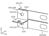
- FIG. 8 is a perspective view showing a configuration of a busbar according to Modification 1 of the embodiment.
- FIG. 9 is a perspective view showing a configuration of a busbar according to Modification 2 of the embodiment.
- a power storage device is a power storage device including a power storage element and a bus bar, wherein the power storage element is a first power storage element and a second power storage element, and the first power storage element is The second power storage element has a first electrode terminal projecting in a first direction, and the second storage element has a second electrode terminal projecting in the first direction, wherein the first electrode terminal extends in a second direction intersecting the first direction.
- the bus bar includes a first connection portion connected to the first electrode terminal, a second connection portion connected to the second electrode terminal, a third connection portion arranged on a current path, wherein the third connection portion protrudes in a direction away from the storage element with respect to the first electrode terminal and the second electrode terminal, and is connected to the conductive member;
- a third connecting portion to be connected wherein the third connecting portion is positioned in the second direction when viewed from a third direction that intersects the first direction and the second direction. It is arranged between the end opposite to the second electrode terminal and the end of the second electrode terminal opposite to the first electrode terminal.
- the bus bar has a third connection portion that protrudes in a direction away from the power storage element and is connected to the conductive member with respect to the first electrode terminal and the second electrode terminal. is arranged from the end of the first electrode terminal of the first storage element to the end of the second electrode terminal of the second storage element in the second direction when viewed from the third direction.
- the bus bar is provided with the third connecting portion projecting in the direction away from the storage element, and the third connecting portion extends from the end of the first electrode terminal to the end of the second electrode terminal when viewed from the third direction. to connect the third connecting portion to the conductive member.
- the conductive member extends from the end of the first electrode terminal to the end of the second electrode terminal in the first direction (directly above the first electrode terminal or the second electrode terminal, etc.) when viewed from the third direction.
- the third connecting portion of the busbar can be easily connected to the conductive member. Therefore, the electric storage element and the conductive member can be easily connected by the bus bar.
- the third connecting portion may be arranged between the center of the first electrode terminal and the center of the second electrode terminal in the second direction when viewed from the third direction.
- the third connecting portion of the bus bar when viewed from the third direction, is located between the center of the first electrode terminal of the first storage element and the center of the second electrode terminal of the second storage element in the second direction. to be placed.
- the conductive member when viewed from the third direction, the conductive member extends from the center of the first electrode terminal to the center of the second electrode terminal in the first direction (such as directly above the center of the first electrode terminal and the second electrode terminal). ), the third connecting portion can be easily connected to the conductive member. Therefore, the electric storage element and the conductive member can be easily connected by the bus bar.
- the bus bar further has a connection portion that connects the first connection portion and the second connection portion, and the third connection portion extends from the second connection portion to the first electrode terminal and the second electrode terminal. , may be arranged so as to protrude in a direction away from the storage element.
- the bus bar has a connection portion that connects the first connection portion and the second connection portion, and the third connection portion protrudes from the second connection portion, so that the bus bar is connected to the first connection portion and the connection portion. , the second connection portion and the third connection portion in this order.
- the busbar can be formed easily by bending one plate-like member.
- the first connecting portion has a first projecting portion that projects in the third direction
- the second connecting portion has a second projecting portion that projects in the third direction
- the connecting portion has a second projecting portion that projects in the third direction.
- the third connecting portion and the connecting portion connecting the one projecting portion and the second projecting portion may be arranged at positions overlapping each other when viewed from the third direction.
- the connecting portion connects the first projecting portion of the first connecting portion and the second projecting portion of the second connecting portion, thereby changing the relative positions of the first connecting portion and the second connecting portion. Even if it deviates, it can absorb the positional deviation and the stress caused by the positional deviation. Therefore, the electric storage element and the conductive member can be easily connected by the bus bar.
- the third connecting portion and the connecting portion may be arranged at positions overlapping each other when viewed from the third direction.
- the third connecting portion 523 and the connecting portion 524 of the bus bar 520 are arranged at positions overlapping each other when viewed from the third direction, so that the third connecting portion 523 and the connecting portion 524 in the second direction are connected to each other.
- a space is secured on the plus side and the minus side when used as a reference, and space saving can be achieved.
- the third connection portion is a third connection portion that is integrally connected to the second connection portion, and the third connection portion is the first power storage element in the second direction of the second connection portion. may protrude from the edge near the
- the third connection portion protrudes from the edge of the second connection portion near the first power storage element in the second direction, thereby A space is secured on both sides of (the positive side and the negative side in the second direction). Therefore, the conductive member can be arranged from both sides in the second direction, and connection (joining) is facilitated.
- the bus bar may be an integrated body in which the first connection portion, the connecting portion, the second connection portion, and the third connection portion are connected in this order.
- the bus bar is connected to the first connection portion, the connection portion, the second connection portion, and the third connection portion in this order. Easy to form.
- the first electrode terminal and the second electrode terminal may have the same polarity.
- the cross-sectional area of the connecting portion perpendicular to the current path may be smaller than the cross-sectional area of the third connecting portion.
- the third connecting portion includes the second connecting portion, the third connecting portion and the conductive member.
- a current flows between
- the first connection portion and the second connection portion flows through the connecting portion.
- the longitudinal direction of the power storage device the direction in which the power storage unit and the control unit are arranged, the direction in which the short sides of the container of the power storage element face each other, or the direction in which the pair of electrode terminals of the power storage element are arranged is Define the X-axis direction.
- the lateral direction of the power storage device, the alignment direction of the power storage element, the busbar plate, the busbar, and the busbar cover, the alignment direction of the body and lid of the container of the power storage element, or the projecting direction of the electrode terminal of the power storage element is the Y-axis direction.
- the direction in which the main body and the lid of the power storage device are arranged, the direction in which the power storage element and the spacer are arranged, the direction in which the long sides of the container of the power storage element face each other, the stacking direction of the electrode plates of the electrode body of the power storage element, or the vertical direction is defined as the Z-axis direction.
- These X-axis direction, Y-axis direction, and Z-axis direction are directions that cross each other (perpendicularly in this embodiment).
- the Z-axis direction may not be the vertical direction, but for convenience of explanation, the Z-axis direction will be described below as the vertical direction.
- the positive direction of the X-axis indicates the direction of the arrow on the X-axis
- the negative direction of the X-axis indicates the direction opposite to the positive direction of the X-axis.
- the Y-axis direction and the Z-axis direction may also be referred to as the first direction
- the Z-axis direction may also be referred to as the second direction
- the X-axis direction may also be referred to as the third direction.
- Expressions indicating relative directions or orientations, such as parallel and orthogonal also include cases where the directions or orientations are not strictly speaking.
- “Two directions are parallel” means not only that the two directions are completely parallel, but also that they are substantially parallel, that is, include a difference of about several percent.
- the expression “insulation” means "electrical insulation”.
- FIG. 1 is a perspective view showing the appearance of a power storage device 1 according to this embodiment.
- FIGS. 2 and 3 are exploded perspective views showing components of the power storage device 1 according to the present embodiment.
- FIG. 3 shows an exploded configuration of the exterior body 100, the storage element 200 and the spacer 300 shown in FIG.
- the power storage device 1 is a device that can charge electricity from the outside and discharge electricity to the outside, and has a substantially rectangular parallelepiped shape in the present embodiment.
- the power storage device 1 may be a battery module (assembled battery) used for power storage or power supply.
- the power storage device 1 is used for driving mobile bodies such as automobiles, motorcycles, water crafts, ships, snowmobiles, agricultural machinery, construction machinery, or railway vehicles for electric railways, or for starting engines. Used as a battery or the like.
- the vehicles include electric vehicles (EV), hybrid electric vehicles (HEV), plug-in hybrid electric vehicles (PHEV), and fossil fuel (gasoline, light oil, liquefied natural gas, etc.) vehicles.
- Examples of railway vehicles for the electric railway include electric trains, monorails, linear motor cars, and hybrid trains having both diesel engines and electric motors.
- the power storage device 1 can also be used as a stationary battery or the like for home or business use.
- the power storage device 1 includes a power storage unit 10 and a control unit 20 , and the power storage unit 10 has an exterior body 100 and a terminal unit 30 . That is, hereinafter, the portion of the power storage device 1 that has the power storage element 200 will be referred to as the power storage unit 10 , and the portion that has the control device that controls the power storage element 200 will be referred to as the control unit 20 . As shown in FIGS.
- the power storage device 1 may include, in addition to the components described above, an exhaust section for discharging gas discharged from the power storage element 200 to the outside of the exterior body 100 .
- the terminal unit 30 is a member having an external terminal 31a that is a module terminal (general terminal) on the positive electrode side or the negative electrode side of the power storage device 1. It is attached to the end in the negative direction of the X-axis.
- the terminal unit 30 has a busbar 31 .
- the bus bar 31 is a plate-like conductive member, which is a conductive member made of metal such as aluminum, aluminum alloy, copper, copper alloy, or nickel, or a combination thereof, or a conductive member other than metal. is formed by
- the bus bar 31 is connected to the bus bar 520 at its positive Y-axis end and has a negative Y-axis end functioning as an external terminal 31a.
- the external terminal 31a may be a negative external terminal.
- bus bar 520 As a result, power storage element 200 of power storage unit 10 and external terminal 31 a are electrically connected via bus bar 520 .
- Bus bar 31 and bus bar 520 are connected (joined) by bolting, but may be connected (joined) by welding or the like.
- the control unit 20 is a device that has a control device (not shown) that controls the power storage elements 200 that the power storage unit 10 has. Specifically, it is a BMS (Battery Management System) that controls the power storage elements 200.
- the control device includes a circuit board, a fuse, a relay, a semiconductor switch such as a FET (Field Effect Transistor), a shunt resistor, and the like, which control charging and discharging of the storage device 200 .
- An external terminal 21 that is a module terminal (general terminal) on the positive electrode side or the negative electrode side of the power storage device 1 is arranged at the end of the exterior body 100 in the positive direction of the X axis and the negative direction of the Y axis.
- the external terminal 21 is a terminal (external terminal on the positive electrode side) having a polarity different from that of the external terminal 31 a of the terminal unit 30 .
- External terminal 21 is electrically connected to storage element 200 .
- the power storage device 1 charges electricity from the outside and discharges electricity to the outside through these external terminals 21 and 31a.
- the external terminals 21 are made of any conductive material or the like that can be used for the busbars 31 .
- the exterior body 100 is a box-shaped (substantially rectangular parallelepiped) container (module case) that constitutes the housing (outer shell) of the power storage device 1 (power storage unit 10).
- the exterior body 100 is arranged outside the power storage elements 200 and the like, fixes the power storage elements 200 and the like at predetermined positions, and protects them from impacts and the like.
- the exterior body 100 includes a first exterior body 110 and a second exterior body 120 arranged side by side in the Z-axis direction, joining members 130 and 140 for joining the first exterior body 110 and the second exterior body 120, and a collar. 150 and .
- the first exterior body 110 is arranged in the Z-axis minus direction of the second exterior body 120 and is a flat rectangular member that constitutes the bottom wall of the exterior body 100, on which the power storage element 200 and the like are placed.
- the second exterior body 120 is a bottomed rectangular tubular member that constitutes the main body of the exterior body 100 (a portion other than the bottom wall), and is connected (joined) to the first exterior body 110 to cover the power storage element 200 and the like.
- the second exterior body 120 has a top wall 120a, a pair of long side walls 120b, and a pair of short side walls 120c.
- the second exterior body 120 has an opening facing in the negative Z-axis direction, and the first exterior body 110 functions as a lid that closes the opening of the second exterior body 120 .
- the first exterior body 110 and the second exterior body 120 are made of metal members such as stainless steel, aluminum, aluminum alloy, iron, steel plate, etc., or insulation treatment such as insulation coating, from the viewpoint of ensuring safety (breakage resistance). It is formed of a highly rigid member such as the metal member to which the The first exterior body 110 and the second exterior body 120 can be formed by aluminum die casting or the like.
- the first exterior body 110 and the second exterior body 120 may be formed of members of the same material, or may be formed of members of different materials.
- connection portions 111 and 112 of the first exterior body 110 and the connection portion 121 and the like of the second exterior body 120 are joined using the joining members 130 and 140 and the collar 150 to form the first
- the exterior body 110 and the second exterior body 120 are connected (fixed).
- the long side wall 120b which is the wall portion (side wall) of the second exterior body 120 in the Y-axis negative direction, is positioned to sandwich the busbar plate 400, the busbars 500 (510 to 530), and the busbar cover 600 with the power storage element 200. placed.
- a through hole 125 is formed in the long side wall 120b.
- the through-hole 125 is a through-hole having a rectangular shape when viewed from the Y-axis direction, which is arranged at the end of the long side wall 120b in the negative direction of the X-axis and penetrates the long side wall 120b in the Y-axis direction.
- the through hole 125 is a through hole through which the bus bar 31 passes when connecting (joining) the bus bar 31 of the terminal unit 30 to the bus bar 520 .
- the first exterior body 110 and the second exterior body 120 are joined together to sandwich the power storage element 200 therebetween. That is, the first exterior body 110 and the second exterior body 120 sandwich and constrain the power storage element 200 in the Z-axis direction, and apply a restraining force to the power storage element 200 in the Z-axis direction.
- the first exterior body 110 and the second exterior body 120 include a plurality of power storage elements 200 arranged in the X-axis direction and the Z-axis direction, and a plurality of spacers 300 (a first spacer 310 and a second spacer 300) arranged in the Z-axis direction.
- first exterior body 110 and the second exterior body 120 are a pair of end plates.
- the power storage element 200 is a secondary battery (single battery) capable of charging and discharging electricity, and more specifically, a non-aqueous electrolyte secondary battery such as a lithium ion secondary battery.
- the power storage element 200 has a flattened rectangular parallelepiped shape (rectangular shape), a plurality of power storage elements 200 are arranged in the X-axis direction, and a plurality of power storage elements 200 are stacked in the Z-axis direction.
- the eight power storage elements 200 are placed horizontally (sideways) (with the long side surfaces 211a of the power storage elements 200, which will be described later, facing the Z-axis direction).
- four power storage elements 201 to 204 are arranged side by side in the X-axis direction from the X-axis minus direction to the X-axis plus direction, and four power storage elements 205 to 208 are arranged from the X-axis minus direction to the X-axis plus direction. are arranged side by side in the X-axis direction.
- Four power storage elements 201 to 204 and four power storage elements 205 to 208 are stacked (flat-stacked) in the Z-axis direction.
- the number of power storage elements 200 is not particularly limited, and any number of power storage elements 200 may be arranged (arranged) in the X-axis direction, and how many power storage elements 200 may be arranged (stacked) in the Z-axis direction.
- the shape of the electric storage element 200 is not limited to the rectangular shape described above, and may be other shapes such as a polygonal columnar shape, a cylindrical shape, an elliptical columnar shape, and an oval columnar shape.
- the storage element 200 is not limited to a non-aqueous electrolyte secondary battery, and may be a secondary battery other than a non-aqueous electrolyte secondary battery, or may be a capacitor.
- the power storage element 200 may be a primary battery that can use stored electricity without being charged by the user, instead of a secondary battery.
- the storage element 200 may be a battery using a solid electrolyte.
- the storage element 200 may be a pouch-type storage element. A detailed description of the configuration of the storage element 200 will be given later.
- the spacer 300 is a rectangular plate-shaped spacer that is aligned with the power storage element 200 in the Z-axis direction and is arranged adjacent to the power storage element 200 .
- Spacer 300 is arranged in the positive Z-axis direction or the negative Z-axis direction of storage element 200 , facing long side surface 211 a of storage element 200 .
- the spacer 300 is made of polycarbonate (PC), polypropylene (PP), polyethylene (PE), polystyrene (PS), polyphenylene sulfide resin (PPS), polyphenylene ether (PPE (including modified PPE)), polyethylene terephthalate (PET), Polybutylene terephthalate (PBT), polyetheretherketone (PEEK), tetrafluoroethylene/perfluoroalkyl vinyl ether (PFA), polytetrafluoroethylene (PTFE), polyethersulfone (PES), polyamide (PA), ABS resin
- PC polycarbonate
- PP polypropylene
- PE polyethylene
- PS polystyrene
- PPS polyphenylene sulfide resin
- PPE polyphenylene ether
- PET polyethylene terephthalate
- PBT Polybutylene terephthalate
- PEEK polyetheretherketone
- PTFE polytetrafluoroethylene
- PTFE poly
- a first spacer 310 and a pair of second spacers 320 are arranged as spacers 300 .
- the first spacer 310 is arranged across the plurality of power storage elements 200 at a position adjacent to the plurality of power storage elements 200 arranged in the X-axis direction in the Z-axis direction.
- the first spacer 310 is positioned adjacent to the four power storage elements 200 (201 to 204 or 205 to 208) aligned in the X-axis direction in the Z-axis direction, and extends across the four power storage elements 200 in the X-axis direction. It is arranged so as to extend in the axial direction.
- the first spacer 310 is an intermediate spacer arranged between the energy storage elements 200 adjacent in the Z-axis direction (between the four energy storage elements 201 to 204 and the four energy storage elements 205 to 208). is.
- the second spacer 320 is arranged across the plurality of power storage elements 200 arranged in the X-axis direction at a position sandwiching the plurality of power storage elements 200 with the first spacer 310 in the Z-axis direction. Specifically, the second spacer 320 and the first spacer 310 sandwich the four energy storage elements 200 (201 to 204 or 205 to 208) aligned in the X-axis direction in the Z-axis direction. 200 extending in the X-axis direction.
- second spacer 320 is an end spacer arranged between power storage element 200 and first exterior body 110 or second exterior body 120 . Specifically, a pair of second spacers 320 are arranged between the four storage elements 205 to 208 and the first exterior body 110 and between the four storage elements 201 to 204 and the second exterior body 120. be done.
- first spacer 310 and the pair of second spacers 320 are arranged so as to sandwich the power storage element 200 in the Z-axis direction, and are spaced between the power storage elements 200 and between the power storage element 200 and the first exterior body 110 . and the second exterior body 120 are insulated.
- the busbar plate 400 is a flat rectangular insulating member that is placed between the power storage element 200 and the busbar 500 and that can insulate the busbar 500 from other members and regulate the position of the busbar 500 .
- Busbar plate 400 may be formed of any insulating resin material or the like that can be used for spacer 300 .
- the busbar plate 400 is arranged in the Y-axis negative direction of the plurality of power storage elements 200 and positioned with respect to the plurality of power storage elements 200 . As a result, the bus bar 500 is positioned with respect to the plurality of power storage elements 200 and joined to electrode terminals 220 (described later) of the plurality of power storage elements 200 .
- the bus bar 500 is a plate-shaped member that is arranged in the Y-axis negative direction of the plurality of storage elements 200 and is connected (bonded) to the plurality of storage elements 200 and the terminal unit 30 .
- three busbars 510 , 520 and 530 are arranged as busbars 500 .
- Bus bar 510 is arranged between bus bar 520 and bus bar 530 and connects electrode terminals 220 of adjacent power storage elements 200 to each other.
- the bus bar 520 is arranged most in the negative direction of the X axis among the plurality of bus bars 500, and connects the electrode terminal 220 of the power storage element 200, which is the most in the negative direction of the X axis, to the bus bar 31 of the terminal unit 30 to connect the power storage element. 200 and the external terminal 31a are electrically connected.
- Bus bar 530 is arranged most in the positive X-axis direction among a plurality of bus bars 500 and electrically connects electrode terminal 220 of storage element 200 in the most positive X-axis direction with external terminal 21 .
- bus bar 500 and electrode terminal 220 of power storage element 200 are connected (joined) by welding, but may be connected (joined) by bolting or the like.
- Bus bar 500 is formed of any conductive material or the like that can be used for bus bar 31 .
- bus bar 500 connects two storage elements 200 in parallel to form four sets of storage element groups, and connects the four sets of storage element groups in series. The form is not particularly limited. A detailed description of the configuration of bus bar 500 will be given later.
- the busbar cover 600 is an insulating cover member that is arranged to cover the busbar 500 and insulates the busbar 500 from other members.
- the busbar cover 600 is a plate-shaped member that extends in the X-axis direction over the plurality of busbars 500 (510 to 530) so as to cover the plurality of busbars 500 (510 to 530).
- the busbar cover 600 is arranged between the busbar 500 and the wall portion of the second exterior body 120 (the long side wall 120b in the negative Y-axis direction). Thereby, the busbar cover 600 insulates the plurality of busbars 500 from other members such as the long side walls 120b.
- the busbar cover 600 is made of any insulating resin material or the like that can be used for the spacers 300 .
- Busbar cover 600 is arranged at a position sandwiching busbar 500 with busbar plate 400 , and has a portion that engages with busbar plate 400 , so that busbar cover 600 is attached and fixed to busbar plate 400 .
- FIG. 4 is an exploded perspective view showing each component by disassembling the power storage device 200 according to the present embodiment. Specifically, FIG. 4 shows an exploded view of each part in a state in which the electric storage device 200 shown in FIG. 3 is placed vertically (upright).
- the electric storage element 200 includes a container 210, a pair of electrode terminals 220 (positive electrode side and negative electrode side), and a pair of gaskets 230 (positive electrode side and negative electrode side).
- a pair of gaskets 240 (positive electrode side and negative electrode side), a pair of current collectors 250 (positive electrode side and negative electrode side), and an electrode assembly 260 are housed inside the container 210 .
- An electrolytic solution non-aqueous electrolyte
- the type thereof is not particularly limited as long as it does not impair the performance of the electric storage element 200, and various kinds can be selected.
- a spacer disposed on the side or below the electrode body 260, an insulating film wrapping the electrode body 260 and the like, an insulating sheet covering the outer surface of the container 210, or the like may be disposed.
- the container main body 211 is a rectangular tubular member that constitutes the main body of the container 210 and has a bottom, and an opening is formed on the Y-axis negative direction side. That is, the container body 211 has a pair of rectangular and planar (flat) long side surfaces 211a on both side surfaces in the Z-axis direction, and a pair of rectangular and planar (flat) side surfaces on both side surfaces in the X-axis direction. a) It has a short side surface 211b and a rectangular and planar (flat) bottom surface 211c on the Y-axis plus direction side.
- the container lid 212 is a rectangular plate-like member that constitutes the lid of the container 210 , and is arranged to extend in the X-axis direction in the negative Y-axis direction of the container body 211 .
- the container cover 212 has a gas discharge valve 212a that releases the pressure inside the container 210 when the pressure rises, and an injection part (not shown) for injecting the electrolytic solution into the container 210. ) etc. are provided.
- the electrode body 260 is a power storage element (power generation element) formed by laminating a positive electrode plate, a negative electrode plate, and a separator.
- the positive electrode plate is formed by forming a positive electrode active material layer on a positive electrode substrate layer, which is a collector foil made of a metal such as aluminum or an aluminum alloy.
- the negative electrode plate is formed by forming a negative electrode active material layer on a negative electrode substrate layer, which is a collector foil made of a metal such as copper or a copper alloy.
- the active material used for the positive electrode active material layer and the negative electrode active material layer any known material can be appropriately used as long as it can intercalate and deintercalate lithium ions.
- electrode body 260 is formed by winding electrode plates (positive electrode plate and negative electrode plate) around a winding axis (virtual axis parallel to the X-axis direction) extending in the X-axis direction. It is a type (so-called vertically wound type) electrode body.
- the flat portion 261 is a flat portion that connects the ends of the pair of curved portions 262, and the curved portion 262 is a portion curved in a semicircular shape or the like so as to protrude in the Y-axis direction.
- the direction in which the flat surface of the flat portion 261 faces or the facing direction of the pair of flat portions 261 can also be defined as the stacking direction. Therefore, it can be said that the power storage elements 201 and 205 are arranged in the stacking direction.
- the X-axis direction in which the power storage elements 201 to 204 are arranged is also called an arrangement direction. That is, the storage elements 201 to 204 are arranged in the arrangement direction crossing the stacking direction. The same applies to the storage elements 205-208.
- the active material is formed (coated) at the ends of the positive electrode plate and the negative electrode plate in the shifted direction. 3) It has a part (active material layer non-formed part) where the base material layer is exposed without being exposed. That is, the electrode body 260 protrudes from the flat portion 261 and the curved portion 262 to both sides in the X-axis direction at both ends in the X-axis direction, and the active material layer non-formed portions of the positive electrode plate and the negative electrode plate are laminated to collect current. It has an end 263 that connects with the body 250 .
- the electrode body 260 may be a so-called horizontal-wound electrode body formed by winding electrode plates around a winding axis extending in the Y-axis direction, or a laminated type electrode body formed by stacking a plurality of flat plate-shaped electrode plates ( Any type of electrode body may be used, such as a stack type electrode body or a bellows-shaped electrode body in which electrode plates are folded into a bellows shape.
- the flat portion is the flat portion other than the curved portion and the connection portion (tab) with the current collector.
- a flat portion is a flat portion other than the connection portion (tab) with the current collector.
- the electrode terminal 220 is a terminal member (a positive terminal and a negative terminal) of the storage element 200, and is arranged on the container lid 212 so as to protrude in the Y-axis negative direction.
- the electrode terminal 220 is electrically connected to the positive plate and the negative plate of the electrode assembly 260 via the current collector 250 .
- the electrode terminal 220 is made of a conductive member such as metal such as aluminum, aluminum alloy, copper, or copper alloy.
- the current collector 250 is a conductive member (a positive electrode current collector and a negative electrode current collector) electrically connected to the electrode terminal 220 and the end portion 263 of the electrode body 260 .
- the current collector 250 is made of aluminum, an aluminum alloy, copper, a copper alloy, or the like.
- the gaskets 230 and 240 are flat insulating sealing members arranged between the container lid 212 and the electrode terminal 220 and current collector 250 . Gaskets 230 and 240 may be formed of any insulating resin material or the like that can be used for spacer 300 .
- FIG. 5 is a perspective view showing the configuration of busbar 500 according to the present embodiment. Specifically, FIG. 5 shows a bus bar 510 and a bus bar 520 in the negative direction of the X axis among the bus bars 500, and the power storage elements 200 (201, 202, 205 and 206) to which the bus bars 510 and 520 are connected. ing. Three busbars 510 out of busbars 500 have the same configuration, and busbars 520 and 530 have the same configuration, so in FIG. .
- the bus bar 510 has a connecting portion 511, a connecting portion 512, a connecting portion 513, a connecting portion 514, a connecting portion 515, a connecting portion 516, and a connecting portion 517.
- the busbar 520 has a connection portion 521 , a connection portion 522 , a connection portion 523 , and a connecting portion 524 .
- the connecting portion 511 is a plate-like and rectangular portion parallel to the XZ plane, which is connected (joined) to the electrode terminal 223 of the power storage element 201 in the positive direction of the X-axis.
- the electrode terminal 223 is a positive electrode terminal (positive terminal) in this embodiment.
- the connection portion 512 is a plate-like rectangular portion parallel to the XZ plane, which is arranged in the Z-axis negative direction of the connection portion 511 and is connected (joined) to the electrode terminal 224 of the power storage element 205 in the X-axis positive direction. is.
- the electrode terminal 224 is a positive electrode terminal (positive terminal) in this embodiment.
- the connecting portion 513 is a plate-like rectangular portion parallel to the XZ plane, which is arranged in the positive direction of the X-axis of the connecting portion 511 and is connected (joined) to the electrode terminal 225 of the power storage element 202 in the negative direction of the X-axis. is.
- the electrode terminal 225 is a negative electrode terminal (negative terminal) in this embodiment.
- the connection portion 514 is a plate-like rectangular portion parallel to the XZ plane, which is arranged in the negative Z-axis direction of the connection portion 513 and is connected (joined) to the electrode terminal 226 of the power storage element 206 in the negative X-axis direction. is.
- the electrode terminal 226 is a negative electrode terminal (negative terminal) in this embodiment.
- the connecting portion 515 is a substantially C-shaped protruding portion that protrudes in the negative Y-axis direction from the edge of the connecting portion 511 in the positive direction of the X-axis and the edge of the connecting portion 513 in the negative direction of the X-axis. is.
- the connecting portion 516 is a substantially C-shaped protruding portion when viewed from the Z-axis direction, protruding in the negative Y-axis direction from the edge of the connecting portion 512 in the positive direction of the X-axis and the edge of the connecting portion 514 in the negative direction of the X-axis. is.
- the connecting portion 517 is a substantially C-shaped concave portion that is recessed in the positive Y-axis direction from the edge of the connecting portion 515 in the negative Z-axis direction and the edge of the connecting portion 516 in the positive Z-axis direction.
- the connecting portion 515 connects the connecting portions 511 and 513
- the connecting portion 516 connects the connecting portions 512 and 514
- the connecting portion 517 connects the connecting portions 515 and 516 .
- the connecting portion 521 is a plate-like and rectangular portion parallel to the XZ plane, which is connected (joined) to the electrode terminal 221 of the power storage element 201 in the negative direction of the X-axis.
- the electrode terminal 221 is a negative electrode terminal (negative terminal) in this embodiment.
- the connecting portion 522 is a flat plate-like rectangular portion parallel to the XZ plane, which is arranged in the negative Z-axis direction of the connecting portion 521 and is connected (joined) to the electrode terminal 222 of the power storage element 205 in the negative X-axis direction. is.
- the electrode terminal 221 is a negative electrode terminal (negative terminal) in this embodiment.
- the connecting portion 523 is a plate-like and rectangular portion parallel to the XY plane that protrudes in the negative Y-axis direction from the edge in the positive Z-axis direction of the portion on the negative X-axis side of the connecting portion 522 . That is, the connecting portion 523 protrudes in the direction opposite to the electric storage element 205 (Y-axis minus direction) with the position of the electrode terminal 222 in the Y-axis direction as a reference.
- the connection portion 523 is connected (joined) to the external terminal 31 a of the bus bar 31 of the terminal unit 30 .
- the connecting portion 524 extends along the Y-axis from the edge of the connecting portion 521 in the positive direction of the X-axis in the negative direction of the Z-axis and the edge of the end of the connecting portion 522 in the positive direction of the X-axis in the positive direction of the Z-axis. It is a substantially C-shaped protruding portion protruding in the negative direction when viewed from the X-axis direction. Thereby, the connecting portion 524 connects the connecting portions 521 and 522 .
- the busbar 520 is an integrated body that connects the connecting portion 521, the connecting portion 524, the connecting portion 522, and the connecting portion 523 in this order, and may be formed by bending a single plate member.
- the third connection portion 523 is connected from the end portion of the second connection portion 522 in the positive Z-axis direction.
- the bus bar 520 can be formed by punching out (shearing) a plate-like member into a rectangular shape and bending the punched-out plate-like member, which facilitates fabrication. It is possible to reduce the loss of the metal plate, which is the material of the bus bar 520, and it is also advantageous from the viewpoint of the number of pieces.
- the configuration of bus bar 520 will be described in more detail below.
- FIG. 6 is a perspective view and a front view showing the configuration of busbar 520 according to the present embodiment.
- FIG. 6A is a perspective view showing a configuration in which bus bar 520 is connected to electrode terminal 221 of storage element 201 and electrode terminal 222 of storage element 205.
- FIG. (b) is a front view showing the configuration when (a) of FIG. 6 is viewed from the Y-axis negative direction.
- FIG. 7 is a cross-sectional view showing the configuration of bus bar 520 and its periphery according to the present embodiment. Specifically, FIG. 7 shows a cross section when the end of the power storage unit 10 in the negative direction of the X axis is cut along a plane parallel to the YZ plane through the connecting portion 523 of the bus bar 520 .
- the storage element 201 is also referred to as the first storage element 201
- the electrode terminal 221 of the storage element 201 is also referred to as the first electrode terminal 221
- the storage element 205 is also referred to as the second storage element 205
- the electrode terminal 222 of the storage element 205 is also referred to as the second storage element 205.
- the second storage element 205 has a second electrode terminal 222 that has the same polarity as the first electrode terminal 221 and protrudes in the Y-axis direction (first direction), and extends in the Z-axis direction (second direction intersecting the first direction). ) has a second electrode terminal 222 arranged in parallel with the first electrode terminal 221 .
- the first electrode terminal 221 and the second electrode terminal 222 have the same polarity, but the polarity is not limited to this.
- connection portion 521 is also called the first connection portion 521
- connection portion 522 is also called the second connection portion 522
- connection portion 523 is also called the third connection portion 523. That is, the busbar 520 has a first connection portion 521 , a second connection portion 522 , a third connection portion 523 , and a connecting portion 524 .
- the first connection portion 521 is connected to the first electrode terminal 221 .
- the second connection portion 522 is connected to the second electrode terminal 222 .
- the third connection portion 523 protrudes from the second connection portion 522 in the Y-axis direction (first direction).
- the connecting portion 524 connects the first connecting portion 521 and the second connecting portion 522 .
- the bus bar 520 connects the first storage element 201 and the second storage element 205 in parallel.
- the first connection portion 521 has a first connection portion body 521a and a first projection portion 521b
- the second connection portion 522 has a second connection portion body 522a and a second projection portion. and a portion 522b.
- the first connecting portion main body 521a is a plate-like and rectangular portion that is joined to the first electrode terminal 221 by welding or the like while being in contact with the first electrode terminal 221 .
- the first projecting portion 521b is a plate-like and rectangular portion that projects from the first connecting portion main body 521a in the X-axis direction (the third direction intersecting the first direction and the second direction).
- the second connecting portion main body 522a is a plate-like and rectangular portion that is joined to the second electrode terminal 222 by welding or the like while being in contact with the second electrode terminal 222 .
- the second protruding portion 522b is a plate-like and rectangular portion that protrudes in the X-axis direction (third direction) from the second connecting portion main body 522a.
- the connecting portion 524 connects the first projecting portion 521b and the second projecting portion 522b. That is, the connecting portion 524 is arranged in the X-axis plus direction from the third connecting portion 523 and connects the first connecting portion 521 and the second connecting portion 522 .
- the connecting portion 524 has a smaller width than the third connecting portion 523 in the X-axis direction (third direction). Specifically, the width B of the connecting portion 524 in the X-axis direction (see (b) of FIG. 6) is smaller than the width A of the third connecting portion 523 in the X-axis direction (see (b) of FIG. 6). .
- the width B of the connecting portion 524 is preferably 1/4 to 3/4 of the width A of the third connecting portion 523, and more preferably 1/2 of the width A. If the width B of the connecting portion 524 and the width A of the third connecting portion 523 are not constant, the minimum value of the width B of the connecting portion 524 is preferably smaller than the minimum value of the width A of the third connecting portion 523. , the maximum value of the width B of the connecting portion 524 is preferably smaller than the minimum value of the width A of the third connection portion 523 . In the present embodiment, the total length of the connecting portion 524 and the third connecting portion 523 in the X-axis direction is less than or equal to the length of the first connecting portion 521 or less than or equal to the length of the second connecting portion 522. Become.
- the connecting portion 524 has the same thickness as the third connecting portion 523.
- the remaining current which is obtained by subtracting the current flowing from the second electrode terminal 222 to the second storage element 205 out of the current flowing through the third connecting portion 523 , flows. Therefore, the current flowing through the connecting portion 524 is smaller than that of the third connecting portion 523 . Therefore, the connecting portion 524 may have a smaller cross-sectional area (cross-sectional area when cut along a plane perpendicular to the direction of current flow) than the third connecting portion 523 .
- the cross-sectional area of the connecting portion 524 is preferably 1/4 to 3/4 of the cross-sectional area of the third connecting portion 523, and more preferably 1/2. If the cross-sectional areas of the connecting portion 524 and the third connecting portion 523 are not constant, the minimum cross-sectional area of the connecting portion 524 is preferably smaller than the minimum cross-sectional area of the third connecting portion 523. More preferably, the maximum cross-sectional area of 524 is smaller than the minimum cross-sectional area of third connection portion 523 .
- the connecting portion 524 preferably has a smaller cross-sectional area (cross-sectional area of a plane perpendicular to the direction of current flow) than the third connecting portion 523 .
- the third connection portion 523 protrudes from the second connection portion main body 522a of the second connection portion 522 in the Y-axis negative direction and is connected to the bus bar 31 (conductive member) of the terminal unit 30.
- the busbar 31 (conductive member) of the terminal unit 30 is a member that is not physically connected to the electrode terminal 220 but has electrical continuity with at least the electrode terminal 220 .
- the busbars 31 (conductive members) of the terminal unit 30 are arranged closer to the external terminals 31a than the busbars 520 in the electrical conduction path.
- the bus bar 520 is distinguished from the bus bar 31 (conductive member) in that it is the bus bar 500 that makes physical contact with the electrode terminal 220 to conduct.
- the third connecting portion 523 is connected (joined) to the bus bar 31 passing through the through hole 125 of the long side wall 120b of the second exterior body 120 by the joining member 34a (see FIG. 7).
- bus bar 520 connects first storage element 201 and second storage element 205 to external terminal 31 a of bus bar 31 .
- the third connection portion 523 is a portion arranged on the main current path instead of a projecting portion or the like for voltage measurement (a portion arranged on the control current path).
- the main current path is the path of the main current of the storage element 200 (the current flowing through the electrode body 260, the electrode terminal 220 and the external terminal 31a).
- the configuration is not limited to this, and the third connection portion 523 may be arranged on a path other than the main current.
- the third connection portion 523 is located on the opposite side of the first electrode terminal 221 to the second electrode terminal 222 in the Z-axis direction (second direction) when viewed from the X-axis direction (third direction). to the end of the second electrode terminal 222 opposite to the first electrode terminal 221 . That is, the third connection portion 523 extends from the end (edge) of the first electrode terminal 221 in the positive Z-axis direction to the negative Z-axis direction of the second electrode terminal 222 in the Z-axis direction when viewed from the X-axis direction.
- the third connection portion 523 extends from the center of the first electrode terminal 221 to the center of the second electrode terminal 222 in the Z-axis direction (second direction) when viewed from the X-axis direction (third direction). is placed between
- the center of the first electrode terminal 221 can also be rephrased as the center of gravity of the surface of the first electrode terminal 221 facing the Y-axis minus direction.
- the center of the first electrode terminal 221 in the Z-axis direction is the distance in the Z-axis direction between the edge of the first electrode terminal 221 in the positive Z-axis direction and the edge of the first electrode terminal 221 in the negative Z-axis direction. Equal position. The same applies to the center of the second electrode terminal 222 (the center of the second electrode terminal 222 in the Z-axis direction).
- the distance from the center of the first electrode terminal 221 to the center of the second electrode terminal 222 in the Z-axis direction means the distance from the center of the first electrode terminal 221 to the center of the second electrode terminal 222.
- This concept also includes positions shifted in the X-axis direction from .
- the third connection portion 523 is located between the first electrode terminal 221 and the second electrode terminal 222 in the Z-axis direction (the edge of the first electrode terminal 221 in the negative direction of the Z-axis and the second electrode terminal). 222 in the Z-axis plus direction).
- busbar 520 has been described in detail above
- busbar 530 also has the same configuration as the busbar 520 as described above.
- bus bar 520 connects the power storage elements (first power storage element 201 and second It has a third connection portion 523 that protrudes in the direction (Y-axis direction) away from the storage element 205) and is connected to the bus bar 31, which is a conductive member.
- the third connection portion 523 extends from the end of the first electrode terminal 221 opposite to the second electrode terminal 222 in the second direction (Z-axis direction) when viewed from the third direction (X-axis direction). It is arranged between the terminal 222 and the end opposite to the first electrode terminal 221 .
- the bus bar 520 is provided with respect to the first electrode terminal 221 and the second electrode terminal 222 in the direction away from the power storage elements (first power storage element 201 and second power storage element 205)
- a third connection portion 523 protruding in the positive direction of the axis is arranged, and the third connection portion 523 is positioned between the end of the first electrode terminal 221 and the end of the second electrode terminal 222 when viewed from the third direction. , and connect the third connection portion 523 to the bus bar 31 .
- the bus bar 31 extends from the end of the first electrode terminal 221 to the end of the second electrode terminal 222 in the first direction (the first electrode terminal 221 or the second electrode terminal 222) when viewed from the third direction.
- the third connection portion 523 of the bus bar 520 can be easily connected to the bus bar 31 . Therefore, the bus bar 520 can easily connect the power storage element 200 and the conductive member (the bus bar 31).
- the first electrode terminal 221 and the second electrode terminal 222 may have the same polarity or opposite polarity.
- the conductive member (bus bar 31) may ensure conduction from the third connection portion 523 to the external terminal 31a.
- the conductive member (bus bar 31) may ensure conduction from the third connection portion 523 to a device such as voltage measurement.
- the bus bar 31 extends from the center of the first electrode terminal 221 to the center of the second electrode terminal 222 in the first direction (the center of the first electrode terminal 221 and the second electrode terminal 222) when viewed from the third direction.
- the third connection portion 523 can be easily connected to the bus bar 31 . Therefore, the bus bar 520 can easily connect the power storage element 200 and the conductive member (the bus bar 31).
- Bus bar 520 has connecting portion 524 that connects first connecting portion 521 and second connecting portion 522 , and third connecting portion 523 protrudes from second connecting portion 522 so that bus bar 520 connects to first connecting portion 521 .
- connecting portion 524 , second connecting portion 522 and third connecting portion 523 are connected in this order.
- the busbar 520 can be formed by bending one plate-like member, so that the busbar 520 can be easily formed.
- the connecting portion 524 connects the first projecting portion 521b of the first connecting portion 521 and the second projecting portion 522b of the second connecting portion 522, thereby connecting the first connecting portion 521 and the second connecting portion 522. Even if the relative position shifts, the position shift and the stress caused by the position shift can be absorbed. Therefore, the bus bar 520 can easily connect the power storage element 200 and the conductive member (the bus bar 31).
- the third connecting portion 523 and the connecting portion 524 of the bus bar 520 are arranged to overlap each other when viewed from the third direction, the positive side and the negative side of the second direction with respect to the third connecting portion 523 and the connecting portion 524 are obtained.
- space can be secured.
- the space can be used for arranging other members or as a space for heat radiation. Space saving can be achieved in the second direction.
- the bus bar 520 includes a third connection portion 523 integrally connected with the second connection portion 522 .
- the third connection portion 523 is configured to protrude from the edge of the second connection portion 522 near the first power storage element 201 in the second direction. That is, the second direction is the thickness direction of the third connection portion 523 . Therefore, since a space is secured on both sides in the second direction (the positive side and the negative side in the second direction) around the third connection portion 523, the conductive member (bus bar 31) can be connected from either side in the second direction. can be arranged, making connection (joining) easier.
- the busbar 520 When the busbar 520 is configured to connect the first connection portion 521, the connection portion 524, the second connection portion 522, and the third connection portion 523 in this order, the busbar 520 can be configured by bending one sheet of plate-like member. 520 can be easily formed. In addition, it is possible to punch the plate-shaped member in a rectangular shape, and it is expected to reduce the loss of the metal plate, which is the material of the bus bar 520, and to increase the number of cuts.
- the first electrode terminal 221 connected to the first connection portion 521 of the bus bar 520 and the second electrode terminal 222 connected to the second connection portion 522 have the same polarity
- the first storage element and the second electrode terminal 222 have the same polarity.
- the third connection portion facilitates connection with the conductive member.
- the third connection portion 523 includes the second connection portion 522 and the third connection portion 523 .
- a current flows between the three-connection portion 523 and the busbar 31 .
- the width of the connecting portion 524 can be made smaller than the width of the third connecting portion 523 in the third direction. As a result, the width of bus bar 520 in the third direction can be reduced, so that space can be saved.
- the cross-sectional area of the connecting portion 524 and the third connecting portion 523 can be made smaller than the cross-sectional area of the third connecting portion 523 . As a result, space can be saved as in the case of reducing the width.
- busbar 520 Although the effect of the busbar 520 has been described above, the busbar 530 also has the same effect as the busbar 520.
- FIG. 8 is a perspective view showing the configuration of bus bar 520a according to Modification 1 of the present embodiment. Specifically, FIG. 8 is a diagram corresponding to (a) of FIG.
- a bus bar 520a is arranged as the bus bar 500 instead of the bus bar 520 in the above embodiment. Since other configurations are the same as those of the above-described embodiment, detailed description thereof will be omitted.
- the busbar 520a has a first connection portion 521c, a second connection portion 522c, a third connection portion 523a, and a connecting portion 524a.
- the first connection portion 521c has the same configuration as the first connection portion main body 521a in the above embodiment. That is, the first connecting portion 521c does not have the first projecting portion.
- the second connection portion 522c includes a second connection portion main body 522d and a second projection portion 522e having the same configurations as the second connection portion main body 522a and the second projection portion 522b of the second connection portion 522 in the above embodiment. have.
- the third connecting portion 523a is a plate-like and rectangular portion parallel to the XY plane that protrudes in the negative Y-axis direction from the edge of the second projecting portion 522e in the positive Z-axis direction.
- the third connection portion 523 a is connected (joined) to a conductive member such as the bus bar 31 of the terminal unit 30 .
- the third connection portion 523a extends from the end of the first electrode terminal 221 opposite to the second electrode terminal 222 in the Z-axis direction (second direction) when viewed from the X-axis direction (third direction). It is arranged between the second electrode terminal 222 and the end opposite to the first electrode terminal 221 .
- the third connection portion 523a extends from the center of the first electrode terminal 221 to the center of the second electrode terminal 222 in the Z-axis direction (second direction) when viewed from the X-axis direction (third direction). placed in between.
- the third connection portion 523a is located between the first electrode terminal 221 and the second electrode terminal 222 in the Z-axis direction when viewed from the X-axis direction, and between the first electrode terminal 221 and the second electrode terminal 222. is arranged in the positive direction of the X-axis.
- the connecting portion 524a is a flat and rectangular portion parallel to the XZ plane that connects the edge of the first connecting portion 521c in the negative Z-axis direction and the edge of the second connecting portion main body 522d in the positive Z-axis direction. be.
- the connecting portion 524a has the same width as the third connecting portion 523a (as well as the first connecting portion 521c and the second connecting portion main body 522d) in the X-axis direction. The width may be smaller than that of the first connecting portion 521c and the second connecting portion main body 522d).
- the connecting portion 524a may protrude in the negative direction of the Y-axis, like the connecting portion 524 in the above embodiment.
- the busbar 520a is an integrated body that connects the first connection portion 521c, the connection portion 524a, the second connection portion 522c, and the third connection portion 523a in this order, and is formed by bending one plate member.
- the bus bar 520a can be formed with a relatively simple configuration.
- the conductive member such as the bus bar 31 connected to the third connection portion 523a is arranged not directly above the first electrode terminal 221 and the second electrode terminal 222 but at a position shifted in the X-axis direction, the conductive member A member can be easily connected to the third connecting portion 523a.
- the third connection portion 523a may be arranged in the negative direction of the X axis relative to the first electrode terminal 221 and the second electrode terminal 222 .
- FIG. 9 is a perspective view showing a configuration of bus bar 520b according to Modification 2 of the present embodiment. Specifically, FIG. 9 is a diagram corresponding to (a) of FIG.
- a bus bar 520b is arranged as a bus bar 500 instead of the bus bar 520 in the above embodiment. Since other configurations are the same as those of the above-described embodiment, detailed description thereof will be omitted.
- the bus bar 520b has a first connection portion 521d, a second connection portion 522f, and a third connection portion 523b.
- the first connection portion 521d has the same configuration as the first connection portion main body 521a in the above embodiment.
- the second connection portion 522f has the same configuration as the second connection portion main body 522a in the above embodiment. That is, the busbar 520b does not have a connecting portion, the first connection portion 521d does not have a first projection, and the second connection portion 522f does not have a second projection.
- the third connection portion 523b includes a plate-like member projecting in the negative Y-axis direction from the edge of the first connection portion 521d in the negative Z-axis direction, and a plate-like member protruding in the negative Y-axis direction from the edge of the second connection portion 522f in the positive Z-axis direction. It is a plate-like and rectangular part parallel to the XY plane, in which a plate-like member protruding in the direction is superimposed.
- the third connection portion 523b is connected (joined) to a conductive member such as the bus bar 31 of the terminal unit 30. As shown in FIG.
- the third connection portion 523b extends from the end of the first electrode terminal 221 opposite to the second electrode terminal 222 in the Z-axis direction (second direction) when viewed from the X-axis direction (third direction). It is arranged between the second electrode terminal 222 and the end opposite to the first electrode terminal 221 . Specifically, the third connection portion 523b extends from the center of the first electrode terminal 221 to the center of the second electrode terminal 222 in the Z-axis direction (second direction) when viewed from the X-axis direction (third direction). placed in between. In this modification, the third connection portion 523b is arranged between the first electrode terminal 221 and the second electrode terminal 222 in the Z-axis direction.
- the same effects as those of the above-described embodiment can be obtained.
- the bus bar 520b can be formed with a relatively simple configuration.
- the second exterior body 120 of the exterior body 100 is a bottomed rectangular tubular member having an opening formed in the negative direction of the Z axis
- the first exterior body 110 is the second exterior body.
- 120 is a flat rectangular member that closes the opening.
- the first exterior body 110 is a bottomed rectangular cylindrical member with an opening formed in the positive direction of the Z axis
- the second exterior body 120 is a flat rectangular shape that closes the opening of the first exterior body 110 . It may be a shaped lid or any other shape.
- Modifications 1 and 2 above The same applies to Modifications 1 and 2 above.
- the conductive member to which the third connection portion 523 of the busbar 520 is connected is the busbar 31 having the external terminal 31a, but any conductive member may be used.
- the third connection portion 523 may pass through the through hole 125 of the second exterior body 120 and be connected to an external conductive member. The same applies to Modifications 1 and 2 above.
- the third connection portion 523 of the bus bar 520 is arranged between the first electrode terminal 221 and the second electrode terminal 222 in the Z-axis direction. It may be arranged at a position slightly shifted in the Z-axis direction from the two-electrode terminal 222 .
- the third connection portion 523 is arranged at a position slightly shifted in the Z-axis direction from the center of the first electrode terminal 221 to the center of the second electrode terminal 222 in the Z-axis direction when viewed from the X-axis direction. good too.
- the third connection portion 523 extends from the end (edge) of the first electrode terminal 221 in the positive Z-axis direction to the negative Z-axis direction of the second electrode terminal 222 in the Z-axis direction when viewed from the X-axis direction. may be arranged between the ends (edges) of the The same applies to Modifications 1 and 2 above.
- the connecting portion 524 of the busbar 520 is arranged to protrude in the negative Y-axis direction from the third connecting portion 523 in the positive X-axis direction.
- the connecting portion 524 may be arranged in the negative direction of the X-axis from the third connecting portion 523 .
- the connecting portion 524 may not protrude in the Y-axis direction, or may protrude in the positive Y-axis direction depending on the shape.
- the connecting portion 524 of the busbar 520 has a smaller width than the third connecting portion 523 in the X-axis direction.
- the connecting portion 524 may have the same width as the third connecting portion 523 or may have a greater width than the third connecting portion 523 in the X-axis direction.
- the bus bar 520 may be provided with connection terminals (protrusions) for voltage measurement.
- connection terminals protrusions
- the bus bar 520 connects the first storage element 201 and the second storage element 205 in parallel.
- bus bar 520 may connect first storage element 201 and second storage element 205 in series.
- the third connection portion 523 can be used as a connection terminal (protrusion) for state detection/measurement such as a voltage detector.
- the third connection portion 523 can also be used as a fin for heat dissipation.
- the container 210 of the storage element 200 has a rectangular parallelepiped shape (square or box shape) having a container body 211 with an opening and a container lid 212 that closes the opening of the container body 211. made a case.
- the container for the power storage element 200 is not limited to a rectangular parallelepiped shape, and may be a pouch type or the like.
- a plurality of power storage elements 200 are arranged horizontally (sideways) in a stacked manner in the Z-axis direction, but the configuration is not limited to this.
- a plurality of power storage elements 200 may be arranged vertically so that the bottom surfaces 200c of the power storage elements 200 are parallel to the XY plane parallel to the X-axis direction and the Y-axis direction.
- the Z-axis direction is the first direction.
- the third connection portion 523 is arranged on the side closer to the electrode terminal 220 in the X-axis direction (minus direction of the X-axis), and the connecting portion is arranged on the side farther from the electrode terminal 220 (plus direction of the X-axis). 524 were placed.
- the configuration is not limited to this, and the positional relationship may be reversed. That is, the connecting portion 524 may be arranged on the side closer to the electrode terminal 220 in the X-axis direction (the negative direction of the X-axis), and the third connecting portion 523 may be arranged on the side farther from the electrode terminal 220 (the positive direction of the X-axis). .
- a power storage device does not need to have all the components described above.
- the power storage device may not include the control unit 20, the terminal unit 30, the exterior body 100, the spacer 300, the busbar plate 400, the busbar cover 600, or the like.
- the present invention can be realized not only as a power storage device, but also as a busbar.
- the present invention can be applied to a power storage device having a power storage element such as a lithium ion secondary battery.
Landscapes
- Chemical & Material Sciences (AREA)
- Chemical Kinetics & Catalysis (AREA)
- Electrochemistry (AREA)
- General Chemical & Material Sciences (AREA)
- Connection Of Batteries Or Terminals (AREA)
Priority Applications (1)
| Application Number | Priority Date | Filing Date | Title |
|---|---|---|---|
| JP2023525668A JPWO2022255017A1 (https=) | 2021-06-04 | 2022-04-28 |
Applications Claiming Priority (2)
| Application Number | Priority Date | Filing Date | Title |
|---|---|---|---|
| JP2021094616 | 2021-06-04 | ||
| JP2021-094616 | 2021-06-04 |
Publications (1)
| Publication Number | Publication Date |
|---|---|
| WO2022255017A1 true WO2022255017A1 (ja) | 2022-12-08 |
Family
ID=84324261
Family Applications (1)
| Application Number | Title | Priority Date | Filing Date |
|---|---|---|---|
| PCT/JP2022/019248 Ceased WO2022255017A1 (ja) | 2021-06-04 | 2022-04-28 | 蓄電装置 |
Country Status (2)
| Country | Link |
|---|---|
| JP (1) | JPWO2022255017A1 (https=) |
| WO (1) | WO2022255017A1 (https=) |
Citations (5)
| Publication number | Priority date | Publication date | Assignee | Title |
|---|---|---|---|---|
| JP2011065794A (ja) * | 2009-09-16 | 2011-03-31 | Toshiba Corp | 二次電池モジュール |
| JP2013197017A (ja) * | 2012-03-22 | 2013-09-30 | Toshiba Corp | 組電池および導電部材 |
| JP2016092005A (ja) * | 2014-11-04 | 2016-05-23 | 株式会社Gsユアサ | 蓄電装置及び蓄電装置の製造方法 |
| JP2019087416A (ja) * | 2017-11-07 | 2019-06-06 | 株式会社東芝 | 組電池 |
| JP2020119653A (ja) * | 2019-01-21 | 2020-08-06 | 矢崎総業株式会社 | 導電モジュール |
Family Cites Families (1)
| Publication number | Priority date | Publication date | Assignee | Title |
|---|---|---|---|---|
| KR102106446B1 (ko) * | 2017-12-08 | 2020-05-04 | 삼성에스디아이 주식회사 | 배터리 모듈 |
-
2022
- 2022-04-28 WO PCT/JP2022/019248 patent/WO2022255017A1/ja not_active Ceased
- 2022-04-28 JP JP2023525668A patent/JPWO2022255017A1/ja active Pending
Patent Citations (5)
| Publication number | Priority date | Publication date | Assignee | Title |
|---|---|---|---|---|
| JP2011065794A (ja) * | 2009-09-16 | 2011-03-31 | Toshiba Corp | 二次電池モジュール |
| JP2013197017A (ja) * | 2012-03-22 | 2013-09-30 | Toshiba Corp | 組電池および導電部材 |
| JP2016092005A (ja) * | 2014-11-04 | 2016-05-23 | 株式会社Gsユアサ | 蓄電装置及び蓄電装置の製造方法 |
| JP2019087416A (ja) * | 2017-11-07 | 2019-06-06 | 株式会社東芝 | 組電池 |
| JP2020119653A (ja) * | 2019-01-21 | 2020-08-06 | 矢崎総業株式会社 | 導電モジュール |
Also Published As
| Publication number | Publication date |
|---|---|
| JPWO2022255017A1 (https=) | 2022-12-08 |
Similar Documents
| Publication | Publication Date | Title |
|---|---|---|
| JP7484178B2 (ja) | 蓄電装置 | |
| JP7852633B2 (ja) | 蓄電装置 | |
| JP7740024B2 (ja) | 蓄電装置 | |
| WO2023013466A1 (ja) | 蓄電装置 | |
| JP2021132016A (ja) | 蓄電装置 | |
| WO2022191231A1 (ja) | 蓄電装置 | |
| US20230275327A1 (en) | Energy storage apparatus | |
| US20240047833A1 (en) | Energy storage apparatus | |
| JP2022123240A (ja) | 蓄電装置 | |
| WO2022255162A1 (ja) | 蓄電装置 | |
| JP7524551B2 (ja) | 蓄電装置 | |
| WO2022255100A1 (ja) | 蓄電装置 | |
| JP2023100001A (ja) | 蓄電装置 | |
| WO2022255017A1 (ja) | 蓄電装置 | |
| WO2023048040A1 (ja) | 蓄電装置 | |
| JP7427903B2 (ja) | 蓄電装置 | |
| JP7275677B2 (ja) | 蓄電装置 | |
| WO2022172941A1 (ja) | 蓄電装置 | |
| JP7845361B2 (ja) | 蓄電装置 | |
| JP2022143582A (ja) | 蓄電装置 | |
| JP7798100B2 (ja) | 蓄電装置 | |
| JP2022029069A (ja) | 蓄電装置 | |
| JP2022029101A (ja) | 蓄電装置 | |
| JP7786049B2 (ja) | 蓄電装置 | |
| JP7838568B2 (ja) | 蓄電装置 |
Legal Events
| Date | Code | Title | Description |
|---|---|---|---|
| 121 | Ep: the epo has been informed by wipo that ep was designated in this application |
Ref document number: 22815772 Country of ref document: EP Kind code of ref document: A1 |
|
| WWE | Wipo information: entry into national phase |
Ref document number: 2023525668 Country of ref document: JP |
|
| NENP | Non-entry into the national phase |
Ref country code: DE |
|
| 122 | Ep: pct application non-entry in european phase |
Ref document number: 22815772 Country of ref document: EP Kind code of ref document: A1 |