WO2022254899A1 - 動画像復号装置および動画像符号化装置 - Google Patents
動画像復号装置および動画像符号化装置 Download PDFInfo
- Publication number
- WO2022254899A1 WO2022254899A1 PCT/JP2022/013833 JP2022013833W WO2022254899A1 WO 2022254899 A1 WO2022254899 A1 WO 2022254899A1 JP 2022013833 W JP2022013833 W JP 2022013833W WO 2022254899 A1 WO2022254899 A1 WO 2022254899A1
- Authority
- WO
- WIPO (PCT)
- Prior art keywords
- prediction
- gpm
- unit
- mode
- transform
- Prior art date
- Legal status (The legal status is an assumption and is not a legal conclusion. Google has not performed a legal analysis and makes no representation as to the accuracy of the status listed.)
- Ceased
Links
Images










Classifications
-
- H—ELECTRICITY
- H04—ELECTRIC COMMUNICATION TECHNIQUE
- H04N—PICTORIAL COMMUNICATION, e.g. TELEVISION
- H04N19/00—Methods or arrangements for coding, decoding, compressing or decompressing digital video signals
- H04N19/46—Embedding additional information in the video signal during the compression process
-
- H—ELECTRICITY
- H04—ELECTRIC COMMUNICATION TECHNIQUE
- H04N—PICTORIAL COMMUNICATION, e.g. TELEVISION
- H04N19/00—Methods or arrangements for coding, decoding, compressing or decompressing digital video signals
- H04N19/10—Methods or arrangements for coding, decoding, compressing or decompressing digital video signals using adaptive coding
- H04N19/102—Methods or arrangements for coding, decoding, compressing or decompressing digital video signals using adaptive coding characterised by the element, parameter or selection affected or controlled by the adaptive coding
- H04N19/119—Adaptive subdivision aspects, e.g. subdivision of a picture into rectangular or non-rectangular coding blocks
-
- H—ELECTRICITY
- H04—ELECTRIC COMMUNICATION TECHNIQUE
- H04N—PICTORIAL COMMUNICATION, e.g. TELEVISION
- H04N19/00—Methods or arrangements for coding, decoding, compressing or decompressing digital video signals
- H04N19/10—Methods or arrangements for coding, decoding, compressing or decompressing digital video signals using adaptive coding
- H04N19/102—Methods or arrangements for coding, decoding, compressing or decompressing digital video signals using adaptive coding characterised by the element, parameter or selection affected or controlled by the adaptive coding
- H04N19/12—Selection from among a plurality of transforms or standards, e.g. selection between discrete cosine transform [DCT] and sub-band transform or selection between H.263 and H.264
-
- H—ELECTRICITY
- H04—ELECTRIC COMMUNICATION TECHNIQUE
- H04N—PICTORIAL COMMUNICATION, e.g. TELEVISION
- H04N19/00—Methods or arrangements for coding, decoding, compressing or decompressing digital video signals
- H04N19/10—Methods or arrangements for coding, decoding, compressing or decompressing digital video signals using adaptive coding
- H04N19/102—Methods or arrangements for coding, decoding, compressing or decompressing digital video signals using adaptive coding characterised by the element, parameter or selection affected or controlled by the adaptive coding
- H04N19/12—Selection from among a plurality of transforms or standards, e.g. selection between discrete cosine transform [DCT] and sub-band transform or selection between H.263 and H.264
- H04N19/122—Selection of transform size, e.g. 8x8 or 2x4x8 DCT; Selection of sub-band transforms of varying structure or type
-
- H—ELECTRICITY
- H04—ELECTRIC COMMUNICATION TECHNIQUE
- H04N—PICTORIAL COMMUNICATION, e.g. TELEVISION
- H04N19/00—Methods or arrangements for coding, decoding, compressing or decompressing digital video signals
- H04N19/10—Methods or arrangements for coding, decoding, compressing or decompressing digital video signals using adaptive coding
- H04N19/134—Methods or arrangements for coding, decoding, compressing or decompressing digital video signals using adaptive coding characterised by the element, parameter or criterion affecting or controlling the adaptive coding
- H04N19/157—Assigned coding mode, i.e. the coding mode being predefined or preselected to be further used for selection of another element or parameter
-
- H—ELECTRICITY
- H04—ELECTRIC COMMUNICATION TECHNIQUE
- H04N—PICTORIAL COMMUNICATION, e.g. TELEVISION
- H04N19/00—Methods or arrangements for coding, decoding, compressing or decompressing digital video signals
- H04N19/10—Methods or arrangements for coding, decoding, compressing or decompressing digital video signals using adaptive coding
- H04N19/134—Methods or arrangements for coding, decoding, compressing or decompressing digital video signals using adaptive coding characterised by the element, parameter or criterion affecting or controlling the adaptive coding
- H04N19/157—Assigned coding mode, i.e. the coding mode being predefined or preselected to be further used for selection of another element or parameter
- H04N19/159—Prediction type, e.g. intra-frame, inter-frame or bidirectional frame prediction
-
- H—ELECTRICITY
- H04—ELECTRIC COMMUNICATION TECHNIQUE
- H04N—PICTORIAL COMMUNICATION, e.g. TELEVISION
- H04N19/00—Methods or arrangements for coding, decoding, compressing or decompressing digital video signals
- H04N19/10—Methods or arrangements for coding, decoding, compressing or decompressing digital video signals using adaptive coding
- H04N19/169—Methods or arrangements for coding, decoding, compressing or decompressing digital video signals using adaptive coding characterised by the coding unit, i.e. the structural portion or semantic portion of the video signal being the object or the subject of the adaptive coding
- H04N19/17—Methods or arrangements for coding, decoding, compressing or decompressing digital video signals using adaptive coding characterised by the coding unit, i.e. the structural portion or semantic portion of the video signal being the object or the subject of the adaptive coding the unit being an image region, e.g. an object
- H04N19/176—Methods or arrangements for coding, decoding, compressing or decompressing digital video signals using adaptive coding characterised by the coding unit, i.e. the structural portion or semantic portion of the video signal being the object or the subject of the adaptive coding the unit being an image region, e.g. an object the region being a block, e.g. a macroblock
-
- H—ELECTRICITY
- H04—ELECTRIC COMMUNICATION TECHNIQUE
- H04N—PICTORIAL COMMUNICATION, e.g. TELEVISION
- H04N19/00—Methods or arrangements for coding, decoding, compressing or decompressing digital video signals
- H04N19/60—Methods or arrangements for coding, decoding, compressing or decompressing digital video signals using transform coding
- H04N19/61—Methods or arrangements for coding, decoding, compressing or decompressing digital video signals using transform coding in combination with predictive coding
-
- H—ELECTRICITY
- H04—ELECTRIC COMMUNICATION TECHNIQUE
- H04N—PICTORIAL COMMUNICATION, e.g. TELEVISION
- H04N19/00—Methods or arrangements for coding, decoding, compressing or decompressing digital video signals
- H04N19/60—Methods or arrangements for coding, decoding, compressing or decompressing digital video signals using transform coding
- H04N19/649—Methods or arrangements for coding, decoding, compressing or decompressing digital video signals using transform coding the transform being applied to non rectangular image segments
-
- H—ELECTRICITY
- H04—ELECTRIC COMMUNICATION TECHNIQUE
- H04N—PICTORIAL COMMUNICATION, e.g. TELEVISION
- H04N19/00—Methods or arrangements for coding, decoding, compressing or decompressing digital video signals
- H04N19/70—Methods or arrangements for coding, decoding, compressing or decompressing digital video signals characterised by syntax aspects related to video coding, e.g. related to compression standards
Definitions
- Embodiments of the present invention relate to a video decoding device and a video encoding device.
- a moving image encoding device that generates encoded data by encoding a moving image and a moving image that generates a decoded image by decoding the encoded data in order to efficiently transmit or record the moving image An image decoding device is used.
- video encoding methods include H.264/AVC and HEVC (High-Efficiency Video Coding).
- the images (pictures) that make up the video are divided into slices obtained by dividing an image, and coding tree units (CTU: Coding Tree Units) obtained by dividing a slice. ), a coding unit obtained by dividing the coding tree unit (Coding Unit: CU)), and a transform unit obtained by dividing the coding unit (TU: Transform Unit), and encoded/decoded for each CU.
- CTU Coding Tree Units
- a predicted image is normally generated based on a locally decoded image obtained by encoding/decoding an input image, and the predicted image is generated from the input image (original image).
- the prediction error obtained by subtraction (sometimes called the "difference image” or “residual image”) is encoded.
- Inter-prediction and intra-prediction are methods for generating predicted images.
- Non-Patent Document 1 discloses a GPM (Geometric partition mode) mode in which a target block is divided into shapes other than rectangles and different inter predictions are performed for each region. By dividing the target block into non-rectangular shapes in this way, even complex textures can be predicted more accurately, and coding efficiency is improved.
- Non-Patent Document 1 discloses an image coding apparatus that performs non-separate transform in order to further concentrate coefficients obtained by separating and transforming prediction errors in a low frequency region for each transform unit.
- Non-Patent Document 1 non-separable transform and inverse non-separable transform techniques that are effective for directional prediction residuals are applied only to intra-predicted blocks, and are not applied to inter-predicted blocks that have many diagonal directions. do not have.
- An object of the present invention is to provide a moving image decoding device, a moving image encoding device, and related technology that can more preferably apply inverse non-separable transform.
- a video decoding device includes a prediction unit that derives a predicted image using a weight parameter derived from an angle variable, and a non-separable transform that performs non-separable transform.
- the separable transform unit derives a non-separable transform set number (lfnstTrSetId) from GPM partition information (merge_gpm_partition_idx) when the inter prediction mode is the GPM mode.
- a video coding apparatus includes a prediction unit that derives a predicted image using a weight parameter derived from an angle variable, and a non-separable transform unit that performs non-separable transform.
- the separable transform unit derives a non-separable transform set number (lfnstTrSetId) from GPM partition information (merge_gpm_partition_idx) when the inter prediction mode is the GPM mode.
- FIG. 1 is a schematic diagram showing the configuration of an image transmission system according to this embodiment
- FIG. FIG. 3 is a diagram showing the hierarchical structure of data in an encoded stream
- 1 is a schematic diagram showing the configuration of a video decoding device
- FIG. 4 is a flowchart for explaining schematic operations of a video decoding device
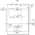
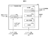
- FIG. 4 is a schematic diagram showing the configuration of an inter-prediction parameter deriving unit
- It is a schematic diagram which shows the structure of an inter prediction image production
- 1 is a block diagram showing the configuration of a video encoding device
- FIG. FIG. 4 is a schematic diagram showing the configuration of an inter-prediction parameter encoding unit
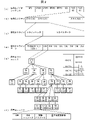
- FIG. 4 is a diagram for explaining GPM prediction
- FIG. 4 is a syntax diagram illustrating coding parameters for GPM prediction
- FIG. 10 is a diagram showing the structure of a table showing the correspondence between merge_gpm_partition_idx and angleIdx and distanceIdx in GPM prediction.
- FIG. 10 is a diagram showing the structure of a table showing the correspondence between idx and DisLut[idx] used in weighting factor derivation processing and motion vector storage processing in GPM prediction; 10 is a flowchart showing the flow of GPM prediction processing;
- intra prediction mode it is a table used for transform matrix selection of non-separable transform.
- In GPM mode it is a table used for transform matrix selection of non-separable transform.
- GPM mode it is a table used for transform matrix selection of non-separable transform.
- GPM mode it is a table used for transform matrix selection of non-separable transform.
- GPM mode it is a table used for transform matrix selection of non-separable transform.
- GPM mode it is a table used for transform matrix selection of non-separable transform.
- 2 is a functional block diagram showing a configuration example of an inverse quantization/inverse transform unit;
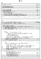
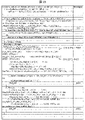
- FIG. It is an example of a syntax table showing coding parameters for GPM non-separable transform.
- 4 is a flow chart showing the flow of processing when non-separable conversion is performed by GPM;
- FIG. 1 is a schematic diagram showing the configuration of an image transmission system 1 according to this embodiment.
- the image transmission system 1 is a system that transmits an encoded stream obtained by encoding a target image, decodes the transmitted encoded stream, and displays the image.
- the image transmission system 1 includes a moving image coding device (image coding device) 11, a network 21, a moving image decoding device (image decoding device) 31, and a moving image display device (image display device) 41. .
- An image T is input to the video encoding device 11 .
- the network 21 transmits the encoded stream Te generated by the video encoding device 11 to the video decoding device 31.
- the network 21 is the Internet, a Wide Area Network (WAN), a Local Area Network (LAN), or a combination thereof.
- the network 21 is not necessarily a two-way communication network, and may be a one-way communication network that transmits broadcast waves such as terrestrial digital broadcasting and satellite broadcasting.
- the network 21 may be replaced by a storage medium such as a DVD (Digital Versatile Disc: registered trademark) or a BD (Blue-ray Disc: registered trademark) that records the encoded stream Te.
- the video decoding device 31 decodes each of the encoded streams Te transmitted by the network 21 and generates one or more decoded decoded images Td.
- the moving image display device 41 displays all or part of one or more decoded images Td generated by the moving image decoding device 31.
- the moving image display device 41 includes, for example, a display device such as a liquid crystal display or an organic EL (Electro-luminescence) display.
- the form of the display includes stationary, mobile, HMD, and the like.
- the moving image decoding device 31 has high processing power, it displays an image with high image quality, and when it has only lower processing power, it displays an image that does not require high processing power and display power. .
- x?y:z is a ternary operator that takes y if x is true (other than 0) and z if x is false (0).
- abs(a) is a function that returns the absolute value of a.
- Int(a) is a function that returns the integer value of a.
- floor(a) is a function that returns the largest integer less than or equal to a.
- ceil(a) is a function that returns the smallest integer greater than or equal to a.
- a/d represents the division of a by d (truncated after the decimal point).
- Fig. 2 is a diagram showing the hierarchical structure of data in the encoded stream Te.
- the encoded stream Te illustratively includes a sequence and a plurality of pictures that constitute the sequence.
- (a) to (f) of FIG. 2 respectively show a coded video sequence that defines a sequence SEQ, a coded picture that defines a picture PICT, a coded slice that defines a slice S, and a coded slice that defines slice data.
- FIG. 3 is a diagram showing data, a coding tree unit included in the coded slice data, and a coding unit included in the coding tree unit;
- the encoded video sequence defines a set of data that the video decoding device 31 refers to in order to decode the sequence SEQ to be processed.
- Sequence SEQ as shown in Figure 2, consists of Video Parameter Set, Sequence Parameter Set SPS, Picture Parameter Set PPS, Adaptation Parameter Set (APS), Picture PICT, and Supplemental Enhancement Information (SEI).
- a video parameter set VPS is a set of coding parameters common to multiple video images, multiple layers included in the video image, and coding parameters related to individual layers. Sets are defined.
- the sequence parameter set SPS defines a set of coding parameters that the video decoding device 31 refers to in order to decode the target sequence. For example, the width and height of the picture are defined. A plurality of SPSs may exist. In that case, one of a plurality of SPSs is selected from the PPS.
- the picture parameter set PPS defines a set of coding parameters that the video decoding device 31 refers to in order to decode each picture in the target sequence. For example, it includes a quantization width reference value (pic_init_qp_minus26) used for picture decoding and a flag (weighted_pred_flag) indicating application of weighted prediction.
- a plurality of PPSs may exist. In that case, one of a plurality of PPSs is selected from each picture in the target sequence.
- the encoded picture defines a set of data that the video decoding device 31 refers to in order to decode the picture PICT to be processed.
- a picture PICT includes slices 0 to NS-1 (NS is the total number of slices included in the picture PICT), as shown in FIG.
- the encoded slice defines a set of data that the video decoding device 31 refers to in order to decode the slice S to be processed.
- a slice includes a slice header and slice data, as shown in FIG.
- the slice header contains a group of coding parameters that the video decoding device 31 refers to in order to determine the decoding method for the target slice.
- Slice type designation information (slice_type) that designates a slice type is an example of a coding parameter included in a slice header.
- Slice types that can be specified by the slice type specifying information include (1) I slices that use only intra prediction during encoding, (2) P slices that use unidirectional prediction or intra prediction during encoding, (3) B slices using uni-prediction, bi-prediction, or intra-prediction during encoding.
- inter prediction is not limited to uni-prediction and bi-prediction, and a predicted image may be generated using more reference pictures.
- P and B slices they refer to slices containing blocks for which inter prediction can be used.
- the slice header may contain a reference (pic_parameter_set_id) to the picture parameter set PPS.
- the encoded slice data defines a set of data that the video decoding device 31 refers to in order to decode slice data to be processed.
- the slice data includes CTU, as shown in FIG. 2(d).
- a CTU is a fixed-size (for example, 64x64) block that forms a slice, and is also called a largest coding unit (LCU).
- FIG. 2 defines a set of data that the video decoding device 31 refers to in order to decode the CTU to be processed.
- CTU uses recursive quad tree partitioning (QT (Quad Tree) partitioning), binary tree partitioning (BT (Binary Tree) partitioning), or ternary tree partitioning (TT (Ternary Tree) partitioning) to perform coding processing. It is divided into coding units CU, which are basic units. BT partitioning and TT partitioning are collectively called multi-tree partitioning (MT (Multi Tree) partitioning).
- MT Multi Tree partitioning
- a node of a tree structure obtained by recursive quadtree partitioning is called a coding node.
- Intermediate nodes of quadtrees, binary trees, and ternary trees are coding nodes, and the CTU itself is defined as the top-level coding node.
- CT includes, as CT information, a CU split flag (split_cu_flag) indicating whether or not to perform CT splitting, a QT split flag (qt_split_cu_flag) indicating whether or not to perform QT splitting, and an MT splitting direction indicating the splitting direction of MT splitting ( mtt_split_cu_vertical_flag), including MT split type (mtt_split_cu_binary_flag) indicating the split type of the MT split.
- split_cu_flag, qt_split_cu_flag, mtt_split_cu_vertical_flag and mtt_split_cu_binary_flag are transmitted for each encoding node.
- Different trees may be used for luminance and color difference.
- the type of tree is indicated by treeType.
- treeType DUAL_TREE_LUMA for luminance
- treeType DUAL_TREE_CHROMA for chrominance.
- FIG. 2 defines a set of data that the video decoding device 31 refers to in order to decode the encoding unit to be processed.
- a CU is composed of a CU header CUH, prediction parameters, transform parameters, quantized transform coefficients, and the like.
- a prediction mode and the like are defined in the CU header.
- Prediction processing may be performed in units of CUs or in units of sub-CUs, which are subdivided into CUs. If the CU and sub-CU sizes are equal, there is one sub-CU in the CU. If the CU is larger than the sub-CU size, the CU is split into sub-CUs. For example, if the CU is 8x8 and the sub-CU is 4x4, the CU is divided into 4 sub-CUs consisting of 2 horizontal divisions and 2 vertical divisions.
- prediction mode The types of prediction (prediction mode) are intra prediction (MODE_INTRA), inter prediction (MODE_INTER), and intra block copy (MODE_IBC). Intra prediction is prediction within the same picture, and inter prediction is prediction processing performed between different pictures (for example, between display times, between layer images).
- the transform/quantization process is performed in CU units, but the quantized transform coefficients may be entropy coded in subblock units such as 4x4.
- prediction parameter A predicted image is derived from the prediction parameters associated with the block.
- the prediction parameters include prediction parameters for intra prediction and inter prediction.
- the intra prediction parameters are composed of a luminance prediction mode IntraPredModeY (predModeIntra) and a color difference prediction mode IntraPredModeC.
- IntraPredModeY predModeIntra
- IntraPredModeC color difference prediction mode
- intra prediction modes for example, planar prediction (0), DC prediction (1), Angular prediction (2-66).
- the inter prediction parameters are composed of prediction list usage flags predFlagL0 and predFlagL1, reference picture indices refIdxL0 and refIdxL1, and motion vectors mvL0 and mvL1.
- predFlagL0 and predFlagL1 are flags indicating whether or not reference picture lists (L0 list, L1 list) are used, and when the value is 1, the corresponding reference picture list is used.
- flag when the term "flag indicating whether or not it is XX" is used, when the flag is other than 0 (for example, 1), it is XX, and 0 is not XX. Treat 1 as true and 0 as false (same below). However, in actual devices and methods, other values can be used as true and false values.
- Syntax elements for deriving inter prediction parameters include, for example, merge flag merge_flag (general_merge_flag), merge index merge_idx, merge_subblock_flag, regulare_merge_flag, and intra inter flag ciip_flag that indicate whether to use subblock-based inter prediction such as affine mode.
- GPM_flag indicating whether to use GPM mode (Geometric partitioning merge mode), merge_gpm_partition_idx indicating the partition shape of GPM mode, merge_gpm_idx0, merge_gpm_idx1 indicating the GPM merge index, inter prediction identifier inter_pred_idc for selecting reference pictures used in AMVP mode , a reference picture index refIdxLX, a predicted vector index mvp_LX_idx for deriving a motion vector, a difference vector mvdLX, and a motion vector precision mode amvr_mode.
- a reference picture list is a list of reference pictures stored in the reference picture memory 306 .
- merge prediction and AMVP prediction There are merge prediction (merge) mode (merge mode) and AMVP (Advanced Motion Vector Prediction, Adaptive Motion Vector Prediction) mode for the prediction parameter decoding (encoding) method, and merge_flag is a flag to identify these.
- the merge mode is a prediction mode that omits part or all of the motion vector difference, and predicts already processed neighboring blocks without including the prediction list usage flag predFlagLX, the reference picture index refIdxLX, and the motion vector mvLX in the encoded data. This mode is derived from parameters and the like.
- AMVP mode is a mode in which inter_pred_idc, refIdxLX, and mvLX are included in encoded data.
- mvLX is encoded as mvp_LX_idx that identifies the prediction vector mvpLX and the difference vector mvdLX.
- general merge mode the generic name of the prediction mode which abbreviate
- general_merge_flag the generic name of the prediction mode which abbreviate
- regular_merge_flag may be transmitted, and if regular_merge_flag is 1, normal merge mode or MMVD may be selected, otherwise CIIP mode or GPM mode may be selected.
- inter_pred_idc is a value that indicates the type and number of reference pictures, and takes one of PRED_L0, PRED_L1, and PRED_BI.
- PRED_L0 and PRED_L1 indicate uni-prediction using one reference picture managed by the L0 list and L1 list, respectively.
- PRED_BI indicates bi-prediction using two reference pictures managed by the L0 list and L1 list.
- merge_idx is an index that indicates which prediction parameter is to be used as the prediction parameter for the target block among the prediction parameter candidates (merge candidates) derived from the blocks for which processing has been completed.
- (motion vector) mvLX indicates the amount of shift between blocks on two different pictures.
- a prediction vector and a difference vector for mvLX are called mvpLX and mvdLX, respectively.
- inter_pred_idc Inter prediction identifier inter_pred_idc and prediction list usage flag predFlagLX
- inter_pred_idc The relationships between inter_pred_idc, predFlagL0, and predFlagL1 are as follows, and can be mutually converted.
- the inter-prediction parameter may use a prediction list usage flag or an inter-prediction identifier. Also, the judgment using the prediction list usage flag may be replaced with the judgment using the inter-prediction identifier. Conversely, the determination using the inter-prediction identifier may be replaced with the determination using the prediction list usage flag.
- the video decoding device 31 includes an entropy decoding unit 301, a parameter decoding unit (prediction image decoding device) 302, a loop filter 305, a reference picture memory 306, a prediction parameter memory 307, a prediction image generation unit (prediction image generation device) 308, an inverse It includes a quantization/inverse transformation unit 311, an addition unit 312, and a prediction parameter derivation unit (not shown).
- the moving image decoding device 31 may have a configuration in which the loop filter 305 is not included in accordance with the moving image encoding device 11 described later.
- the parameter decoding unit 302 further includes a header decoding unit 3020, a CT information decoding unit 3021, and a CU decoding unit 3022 (prediction mode decoding unit), and the CU decoding unit 3022 further includes a TU decoding unit 3024. These may be collectively called a decoding module.
- Header decoding section 3020 decodes parameter set information such as VPS, SPS, PPS, and APS, and slice headers (slice information) from encoded data.
- CT information decoding section 3021 decodes CT from encoded data.
- a CU decoding unit 3022 decodes a CU from encoded data.
- TU decoding section 3024 decodes QP update information (quantization correction value) and quantization prediction error (residual_coding) from encoded data when prediction error is included in TU.
- the header decoding unit 3020 decodes the flag sps_lfnst_enabled_flag indicating whether or not to use the non-separate transform from the SPS. Also, when the sps_lfnst_enabled_flag is 1, the header decoding unit 3020 decodes the ph_lfnst_enabled_flag from the picture header (PH). Infer ph_lfnst_enabled_flag to 0 if ph_lfnst_enabled_flag does not appear.
- the value of sps_lfnst_enabled_flag may be set as the value of ph_lfnst_enabled_flag.
- the GPM non-separable transform in the present invention is the inverse non-separable transform (and non-separable transform) when inter prediction is in GPM mode.
- a method of deriving a non-separable transformation matrix or a set of transformation matrices from a GPM partition shape when adapted to an inter CU will be described below.
- Fig. 21 is an example of a syntax table showing coding parameters for GPM non-separable transform.
- the header decoding unit 3020 decodes the flag sps_gpm_lfnst_enabled_flag from the SPS.
- sps_gpm_lfnst_enabled_flag is a flag indicating whether to use GPM non-separable transform in the case of GPM prediction.
- header decoding section 3020 decodes sps_gpm_lfnst_enabled_flag.
- sps_gpm_enabled_flag is a flag indicating whether the GPM prediction mode is used in the target sequence.
- the TU decoding unit 3024 decodes the index mts_idx indicating the transform basis from the encoded data. Also, the TU decoding unit 3024 decodes the parameter lfnst_idx indicating whether non-separable transform is used and the transform basis from the encoded data. Specifically, the TU decoding unit 3024 decodes lfnst_idx when the width and height of the CU are 4 or more and the prediction mode is the intra prediction mode.
- the predicted image generation unit 308 includes an inter predicted image generation unit 309 (FIG. 6) and an intra predicted image generation unit 310.
- the prediction parameter derivation unit includes an inter prediction parameter derivation unit 303 (Fig. 5) and an intra prediction parameter derivation unit.
- CTU and CU as processing units
- processing may be performed in sub-CU units.
- CTU and CU may be read as blocks
- sub-CU may be read as sub-blocks
- processing may be performed in units of blocks or sub-blocks.
- the entropy decoding unit 301 performs entropy decoding on the encoded stream Te input from the outside to decode individual codes (syntax elements).
- syntax elements For entropy coding, a method of variable-length coding syntax elements using a context (probability model) adaptively selected according to the type of syntax elements and surrounding circumstances, a predetermined table, or There is a method of variable-length coding syntax elements using a formula.
- the entropy decoding unit 301 outputs the decoded code to the parameter decoding unit 302.
- the decoded codes are, for example, prediction modes predMode, merge_flag, merge_idx, inter_pred_idc, refIdxLX, mvp_LX_idx, mvdLX, amvr_mode, and the like. Control of which code is to be decoded is performed based on an instruction from parameter decoding section 302 .
- FIG. 4 is a flow chart for explaining a schematic operation of the video decoding device 31. As shown in FIG.
- the header decoding unit 3020 decodes parameter set information such as VPS, SPS, and PPS from the encoded data.
- the header decoding unit 3020 decodes the slice header (slice information) from the encoded data.
- the video decoding device 31 derives a decoded image of each CTU by repeating the processing from S1300 to S5000 for each CTU included in the target picture.
- the CT information decoding unit 3021 decodes the CTU from the encoded data.
- the CT information decoding unit 3021 decodes the CT from the encoded data.
- the CU decoding unit 3022 performs S1510 and S1520 to decode the CU from the encoded data.
- the CU decoding unit 3022 decodes CU information, prediction information, TU split flag split_transform_flag, CU residual flags cbf_cb, cbf_cr, cbf_luma, etc. from the encoded data.
- TU decoding section 3024 decodes quantized prediction error and transform index mts_idx from encoded data when prediction error is included in TU.
- the predicted image generation unit 308 generates a predicted image based on the prediction information for each block included in the target CU.
- the inverse quantization/inverse transform unit 311 executes inverse quantization/inverse transform processing for each TU included in the target CU.
- the addition unit 312 adds the predicted image supplied from the predicted image generation unit 308 and the prediction error supplied from the inverse quantization/inverse transform unit 311, thereby decoding the target CU. Generate an image.
- the loop filter 305 applies a loop filter such as a deblocking filter, SAO, and ALF to the decoded image to generate a decoded image.
- a loop filter such as a deblocking filter, SAO, and ALF
- the intra prediction parameter deriving unit Based on the code input from the entropy decoding unit 301, the intra prediction parameter deriving unit refers to the prediction parameters stored in the prediction parameter memory 307 and decodes the intra prediction parameters, for example, the intra prediction mode IntraPredMode.
- the intra prediction parameter derivation unit outputs the decoded intra prediction parameters to the prediction image generation unit 308 and stores them in the prediction parameter memory 307 .
- the intra prediction parameter derivation unit may derive different intra prediction modes for luminance and color difference.
- a loop filter 305 is a filter provided in the encoding loop, and is a filter that removes block distortion and ringing distortion and improves image quality.
- a loop filter 305 applies filters such as a deblocking filter, a sample adaptive offset (SAO), and an adaptive loop filter (ALF) to the decoded image of the CU generated by the addition unit 312 .
- filters such as a deblocking filter, a sample adaptive offset (SAO), and an adaptive loop filter (ALF) to the decoded image of the CU generated by the addition unit 312 .
- the reference picture memory 306 stores the decoded image of the CU generated by the adding unit 312 in a predetermined position for each target picture and target CU.
- the prediction parameter memory 307 stores prediction parameters in predetermined positions for each CTU or CU to be decoded. Specifically, the prediction parameter memory 307 stores the parameters decoded by the parameter decoding unit 302, the prediction mode predMode separated by the entropy decoding unit 301, and the like.
- a prediction mode predMode, prediction parameters, etc. are input to the prediction image generation unit 308 .
- the predicted image generation unit 308 reads a reference picture from the reference picture memory 306 .
- the predicted image generating unit 308 generates a predicted image of a block or sub-block using the prediction parameter and the read reference picture (reference picture block) in the prediction mode indicated by the prediction mode predMode.
- a reference picture block is a set of pixels on a reference picture (usually rectangular and therefore called a block), and is an area referred to for generating a prediction image.
- the intra-predicted image generating unit 310 refers to the read decoded pixel values and the prediction mode indicated by IntraPredMode to generate a predicted image of the target block.
- the intra prediction image generation unit 310 outputs the generated block prediction image to the addition unit 312 .
- Inter prediction parameter derivation section 303 derives inter prediction parameters by referring to prediction parameters stored in prediction parameter memory 307 based on syntax elements input from parameter decoding section 302 . Also, inter prediction parameters are output to inter prediction image generation section 309 and prediction parameter memory 307 .
- the inter-prediction parameter derivation unit 303 and its internal elements, the AMVP prediction parameter derivation unit 3032, the merge prediction parameter derivation unit 3036, the GPM prediction unit 30377, and the MV addition unit 3038, are common to the video encoding device and the video decoding device. Since these are means for deriving motion vectors, they may be collectively referred to as motion vector derivation units (motion vector derivation devices).
- GPM_Flag 1, that is, indicates the GPM prediction mode
- the GPM prediction unit 30377 derives GPM prediction parameters.
- merge_idx is derived and output to the merge prediction parameter derivation unit 3036.
- the AMVP prediction parameter derivation unit 3032 derives mvpLX from inter_pred_idc, refIdxLX or mvp_LX_idx.
- the MV adder 3038 adds the derived mvpLX and mvdLX to derive mvLX.
- the merge prediction parameter derivation unit 3036 includes a merge candidate derivation unit and a merge candidate selection unit.
- the merge candidates are configured including prediction parameters (predFlagLX, mvLX, refIdxLX) and stored in the merge candidate list.
- the merge candidates stored in the merge candidate list are assigned indices according to a predetermined rule.
- the merge candidate derivation unit derives merge candidates using the decoded adjacent block motion vectors and refIdxLX as they are.
- the merge candidate derivation unit may apply spatial merge candidate derivation processing, temporal merge candidate derivation processing, and the like, which will be described later.
- the merge candidate derivation unit reads the prediction parameters stored in the prediction parameter memory 307 according to a predetermined rule and sets them as merge candidates.
- the method of specifying the reference picture is, for example, all or part of the adjacent blocks within a predetermined range from the target block (for example, all or part of the blocks that touch the left A1, right B1, upper right B0, lower left A0, and upper left B2 of the target block, respectively).
- ) are prediction parameters for each of Call each merge candidate A1, B1, B0, A0, B2.
- A1, B1, B0, A0, B2 are each motion information derived from a block containing the following coordinates:
- the merge candidate derivation unit reads out the prediction parameters of the block C in the reference image including the lower right CBR of the target block or the center coordinates from the prediction parameter memory 307 and sets them as merge candidates Col. Store in candidate list mergeCandList[].
- mergeCandList[] The order of storing in mergeCandList[] is, for example, spatial merge candidate (B1, A1, B0, A0, B2), temporal merge candidate Col. Note that reference blocks that are not available (blocks are intra-predicted, etc.) are not stored in the merge candidate list.
- the merge candidate selection unit selects the merge candidate N indicated by merge_idx from among the merge candidates included in the merge candidate list using the following formula.
- N mergeCandList[merge_idx]
- N is a label indicating a merge candidate, such as A1, B1, B0, A0, B2, Col.
- the motion information of the merge candidate indicated by label N is indicated by (mvLXN[0], mvLXN[0]), predFlagLXN, and refIdxLXN.
- the merge candidate selection unit stores the inter prediction parameters of the selected merge candidates in the prediction parameter memory 307 and outputs them to the inter prediction image generation unit 309 .
- GPM prediction GPM prediction is explained.
- GPM prediction is prediction used in GPM mode, and generates a predicted image as two non-rectangular prediction units that divide the target CU by a line segment.
- FIG. 9(a) shows an example of a straight line segment.
- a straight line segment spanning the target CU is defined by an angle index angleIdx (angle variable) and a distance index distanceIdx (distance variable) shown in FIG. 9(b).
- angleIdx indicates the angle ⁇ between a vertical straight line and the straight line segment.
- distanceIdx indicates the distance ⁇ from the center of the target CU to the straight line segment.
- angleIdx is an integer value assigned to the angle of a straight line segment.
- 360 degrees when 360 degrees are roughly divided into 32, the values shown in FIG. 9(c) are assigned.
- 360 degrees are divided into 32 using square scales (coordinates) instead of perfectly equal division.
- 360 degrees may be divided into 64, and a finer angle index may be sent.
- GPM prediction In the prediction image generation of GPM prediction, two “rectangular” prediction images (temporary prediction images) containing non-rectangular prediction units are derived, and the above two rectangular regions are weighted according to the shape of the non-rectangular prediction unit. It may be derived by doing
- the motion compensation unit 3091 derives two temporary predicted images of the target CU, and the GPM synthesizing unit 30952 weights each pixel of the two temporary predicted images according to the position of the pixel to generate a predicted image. to derive This processing is called GPM synthesis processing. Processing other than prediction (eg transform (inverse transform) and quantization (inverse quantization)) is applied to the entire target CU.
- prediction eg transform (inverse transform) and quantization (inverse quantization)
- the GPM prediction unit 30377 derives prediction parameters for the two non-rectangular regions and supplies them to the inter prediction image generation unit 309.
- GPM prediction may be configured without bi-prediction for simplification of processing.
- inter-prediction parameters for unidirectional prediction are derived for non-rectangular regions.
- sps_gpm_enabled_flag is notified by SPS and indicates whether the GPM prediction mode is used in the target sequence. If sps_gpm_enabled_flag is 0, it indicates that GPM prediction mode is not used in the target sequence. When sps_gpm_enabled_flag is 1, it indicates that the GPM prediction mode is used in the target sequence.
- the GPM prediction mode in which the number of selectable split patterns (split types) is NumGPMFull (for example, 64) is used in the target sequence.
- sps_gpm_enabled_flag is not limited to SPS, and may be transmitted in PPS, picture header, or slice header.
- Fig. 10(b) is a diagram showing the syntax configuration notified in merge mode.
- the parameter decoding unit 302 decodes syntax elements in the encoded data, and the GPM prediction unit 30377 (inter prediction parameter derivation unit 303) derives GPM prediction parameters according to the following rules.
- sps_max_num_merge_cand_minus_max_num_gpm_cand is notified.
- sps_max_num_merge_cand_minus_max_num_gpm_cand is a parameter used to derive the maximum number of merge candidates for GPM prediction, MaxNumGpmMergeCand.
- the GPM prediction unit 30377 derives merge candidate MergeCand from 0 to the maximum number of merge prediction candidates MaxNumMergeCand-1.
- MaxNumGpmMergeCand is 3 or more
- MaxNumGpmMergeCand MaxNumMergeCand - sps_max_num_merge_cand_minus_max_num_gpm_cand If sps_gpm_enabled_flag is on and MaxNumMergeCand is 2, derive MaxNumGpmMergeCand as follows:
- MaxNumGpmMergeCand 2 If none of the above apply, derive MaxNumGpmMergeCand by the following formula.
- MaxNumGpmMergeCand 0 When MaxNumGpmMergeCand is 0, GPM prediction is disabled.
- merge_data() is a syntax construct that informs the parameters of the merge prediction.
- merge_gpm_partition_idx is an index (partition index) indicating a partition pattern in GPM prediction mode.
- the partition index indicates a combination of angleIdx and distanceIdx specifying a straight line segment across the target block for dividing the target block into two non-rectangular regions.
- Merge candidates are used as the motion information used to generate predicted images for GPM prediction.
- merge_gpm_idx0 and merge_gpm_idx1 are indices of merge candidates indicating motion information of two non-rectangular regions respectively.
- the parameter decoding unit 302 decodes merge_gpm_partition_idx, merge_gpm_idx0, and merge_gpm_idx1.
- the parameter decoding unit 302 may decode merge_gpm_partition_idx and merge_gpm_idx0 if !ciip_flag, and further decode merge_gpm_idx1 if MaxNumGpmMergeCand>2.
- the GPM prediction unit 30377 derives merge indices m and n from syntax elements merge_gpm_idx0 and merge_gpm_idx1 indicating motion information for two non-rectangular regions as follows.
- merge candidate indicated by merge index m is indicated as M
- merge candidate indicated by merge index n is indicated as N.
- a merge prediction parameter derivation unit 3036 derives motion information (mvLXM, mvLXN, refIdxLXM, refIdxLXN, predFlagLXM, predFlagLXN, bcwIdx, mergeCandList, etc.) of merge candidates M and N by the method described in (Merge prediction).
- the GPM prediction unit 30377 sets motion vectors mvA and mvB of merge_gpm_idx0 and merge_gpm_idx1, reference indices refIdxA and refIdxB, and prediction list flags predListFlagA and predListFlagB using these pieces of motion information.
- the GPM prediction unit 30377 derives angleIdx and distanceIdx corresponding to merge_gpm_partition_idx according to the table shown in FIG.
- the GPM synthesizing unit 30952 derives a predicted image using weight parameters derived from angle variables. More specifically, a predicted image is generated using weight information derived using angleIdx and distanceIdx and temporary predicted images predSamplesLA and predSamplesLB.
- the GPM synthesizing unit 30952 sets bitDepth to the luminance pixel bit number BitDepthY.
- the GPM synthesis unit 30952 sets nW and nH to nCbW and nCbH, respectively. If cIdx is not 0, the GPM combiner 30952 sets nW and nH to nCbW*SubWidthC and nCbH*SubHeightC, respectively.
- SubWidthC and SubHeightC are values predetermined according to the color difference format.
- the GPM synthesizing unit 30952 sets both subW and subH to 1. If cIdx is not 0, the GPM synthesizing section 30952 sets SubWidthC and SubHeightC to subW and subH, respectively.
- the GPM synthesizing unit 30952 sets bitDepth to the color difference pixel bit number BitDepthC.
- the GPM synthesizing unit 30952 derives variables nW, nH, shift1, offset1, displacementX, displacementY, partFlip and shiftHor as follows.
- the GPM synthesizing unit 30952 derives generalized coordinates (xL, yL) from the coordinates (x, y) in the CU.
- the GPM synthesizing unit 30952 uses disLut shown in FIG. 12 to calculate weighting factors wValue according to the coordinates in the CU as follows.
- the GPM synthesizing unit 30952 derives the value of pbSample as follows.
- pbSamples[x][y] Clip3(0, (1 ⁇ BitDepth) - 1, (predSamplesLA[x][y] * wValue + predSamplesLB[x][y] * (8 - wValue) + offset1) >> shift1) (Motion vector storage processing in GPM prediction)
- the GPM prediction unit 30377 converts motion vectors (mvA, mvB) of non-rectangular areas A and B and reference picture information (predFlagA, prefFlagB, refIdxLA, refIdxLB) into 4*4 subblock units so that they can be referred to in subsequent processing. to store in memory.
- FIG. 13 is a flowchart showing the flow of GPM prediction processing.
- the parameter decoding unit 302 appropriately decodes various syntax elements notified by SPS, PPS, slice header, merge data, etc., as shown in FIG. 4, for example. Then, these syntax elements are output to the inter prediction parameter derivation unit 303 (merge prediction parameter derivation unit 3036, GPM prediction unit 30377, etc.).
- the GPM prediction unit 30377 determines whether or not MergeGpmFlag is 1.
- the GPM prediction unit 30377 performs GPM prediction processing in S3503-S3505.
- the GPM prediction unit 30377 derives motion information and further generates two temporary predicted images predSamplesLA and predSamplesLB.
- the GPM prediction unit 30377 derives the weighting factor wValue, and the GPM synthesis unit 30952 generates a predicted image.
- the GPM prediction unit 30377 stores motion vectors in memory.
- the AMVP prediction parameter derivation unit 3032 includes a vector candidate derivation unit and a vector candidate selection unit.
- the vector candidate deriving unit derives vector predictor candidates from motion vectors of decoded adjacent blocks stored in the prediction parameter memory 307 based on refIdxLX, and stores them in a vector predictor candidate list mvpListLX[].
- the vector candidate selection unit selects the motion vector mvpListLX[mvp_LX_idx] indicated by mvp_LX_idx as mvpLX from among the vector prediction candidates of mvpListLX[].
- the vector candidate selection unit outputs the selected mvpLX to the MV addition unit 3038.
- MV adding section 3038 adds mvpLX input from AMVP prediction parameter deriving section 3032 and decoded mvdLX to calculate mvLX. Addition section 3038 outputs calculated mvLX to inter prediction image generation section 309 and prediction parameter memory 307 .
- inter prediction image generation section 309 When predMode indicates the inter prediction mode, inter prediction image generation section 309 generates a prediction image of a block or sub-block by inter prediction using inter prediction parameters and reference pictures input from inter prediction parameter derivation section 303 .
- FIG. 6 is a schematic diagram showing the configuration of the inter predicted image generation unit 309 included in the predicted image generation unit 308 according to this embodiment.
- the inter predicted image generation unit 309 includes a motion compensation unit (predicted image generation device) 3091 and a synthesizing unit 3095 .
- the synthesizing section 3095 includes an IntraInter synthesizing section 30951 , a GPM synthesizing section 30952 , a BIO section 30954 and a weight predicting section 3094 .
- the motion compensation unit 3091 (interpolated image generation unit 3091) performs interpolation by reading reference blocks from the reference picture memory 306 based on the inter prediction parameters (predFlagLX, refIdxLX, mvLX) input from the inter prediction parameter derivation unit 303. Generate an image (motion compensated image).
- the reference block is a block on the reference picture RefPicLX specified by refIdxLX, which is shifted by mvLX from the position of the target block.
- refIdxLX a filter that is shifted by mvLX from the position of the target block.
- an interpolated image is generated by applying a filter called a motion compensation filter for generating pixels at decimal positions.
- the motion compensation unit 3091 first derives the integer position (xInt, yInt) and phase (xFrac, yFrac) corresponding to the intra-prediction block coordinates (x, y) using the following equations.
- the motion compensation unit 3091 derives a temporary image temp[][] by performing horizontal interpolation processing on the reference picture refImg using an interpolation filter.
- shift1 is a normalization parameter that adjusts the range of values
- offset1 1 ⁇ (shift1-1).
- temp[x][y] ( ⁇ mcFilter[xFrac][k]*refImg[xInt+k-NTAP/2+1][yInt]+offset1)>>shift1
- the motion compensation unit 3091 derives an interpolated image Pred[][] by subjecting the temporary image temp[][] to vertical interpolation processing.
- shift2 is a normalization parameter that adjusts the range of values
- offset2 1 ⁇ (shift2-1).
- Pred[x][y] ( ⁇ mcFilter[yFrac][k]*temp[x][y+k-NTAP/2+1]+offset2)>>shift2
- the above Pred[][] is derived for each L0 list and L1 list (referred to as interpolated images PredL0[][] and PredL1[][]), and PredL0[][] and PredL1[ ][] to generate an interpolated image Pred[][].
- IntraInter synthesizing unit 30951 When ciip_mode is 1, the IntraInter synthesizing unit 30951 generates a CIIP (Combined intra inter prediction) mode prediction image by weighting the sum of the inter prediction image and the intra prediction image.
- CIIP Combined intra inter prediction
- the prediction value in CIIP mode is calculated by the weighted average of the inter-predicted image derived in merge mode and the intra-predicted image derived in planar prediction. Combining weights are determined by the prediction modes of adjacent coded blocks. If intra-prediction is used in both of the two adjacent blocks (upward and leftward) of the current block, the inter-prediction and intra-prediction combining ratio is 1:3. On the other hand, if neither of the two adjacent blocks are intra prediction, the synthesis ratio of inter prediction and intra prediction is set to 3:1. Otherwise, the ratio is 2:2. The same weighting factor is applied to both luminance and chrominance.
- BIO unit 30954 refers to two predicted images (first predicted image and second predicted image) and a gradient correction term to generate a predicted image in the bi-prediction mode.
- the weight prediction unit 3094 generates a block prediction image by multiplying the interpolation image PredLX by a weighting factor.
- PredFlagL0 or predFlagL1 is 1 (uni-prediction) and weight prediction is not used, the following equation processing is performed to adjust PredLX (LX is L0 or L1) to the pixel bit number bitDepth.
- the weight prediction unit 3094 derives the weight prediction coefficient w0 and the offset o0 from the encoded data, and performs the processing of the following formula.
- Pred[x][y] Clip3(0,(1 ⁇ bitDepth)-1,((PredLX[x][y]*w0+2 ⁇ (log2WD-1))>>log2WD)+o0)
- log2WD is a variable indicating a predetermined shift amount.
- the weight prediction unit 3094 derives weight prediction coefficients w0, w1, o0, and o1 from the encoded data, and performs the processing of the following equations.
- Pred[x][y] Clip3(0,(1 ⁇ bitDepth)-1,(PredL0[x][y]*w0+PredL1[x][y]*w1+((o0+o1+1) ⁇ log2WD))>>(log2WD+1))
- the inter predicted image generating unit 309 outputs the generated block predicted image to the adding unit 312 .
- the intra prediction image generation unit performs intra prediction using the intra prediction parameters input from the intra prediction parameter derivation unit and the reference pixels read from the reference picture memory 306 .
- the inverse quantization/inverse transform unit 311 inversely quantizes the quantized transform coefficients input from the parameter decoding unit 302 to obtain transform coefficients.
- FIG. 20 is a block diagram showing the configuration of the inverse quantization/inverse transform unit 311 of this embodiment.
- the inverse quantization/inverse transform unit 311 is composed of a scaling unit 31111 , an inverse non-separable transform unit 31121 and an inverse core transform unit 31123 .
- the inverse quantization/inverse transform unit 311 scales (inverse quantizes) the quantized transform coefficients qd[][] input from the entropy decoding unit 301 by the scaling unit 31111 to obtain transform coefficients d[][].
- This quantized transform coefficient qd[][] is quantized by transforming the prediction error, such as DCT (Discrete Cosine Transform) or DST (Discrete Sine Transform), in the encoding process. or the coefficients obtained by further non-separating transformation of the transformed coefficients.
- inverse frequency transform such as inverse DCT and inverse DST is performed on the transform coefficients to calculate prediction errors.
- Inverse quantization/inverse transform section 311 outputs the prediction error to addition section 312 .
- transformation and inverse transformation may be interpreted by replacing each other.
- the transform may be called a forward transform.
- the non-separable transform the non-separable transform
- the forward non-separable transform the non-separable transform
- core transformations are simply referred to as transformations.
- d[x][y] is transmitted to the inverse core transform unit 31123 or the inverse non-separable transform unit 31121.
- the inverse non-separable transform unit 31121 applies an inverse non-separable transform to the transform coefficients d[][] after the inverse quantization and before the core transform.
- the inverse non-separable transform is applied to the transform coefficients of part or all of the TU in the video decoding device 31 .
- an inverse separable transform (such as DCT2 and DST7) is applied to the transform coefficients after the inverse non-separable transform.
- the non-separable transform and the inverse non-separable transform are applied only to a predetermined upper left sub-block.
- TU sizes where one of TU width W and height H is 4 are, for example, 4 ⁇ 4, 8 ⁇ 4, 4 ⁇ 8, L ⁇ 4, and 4 ⁇ L (L is a natural number of 16 or more). is mentioned.
- RST Reduced Secondary Transform
- LFNST Low Frequency Non-Separable-Transform
- the number nonZeroSize of the transform coefficients of the non-separable transform to be transmitted is equal to or smaller than the size of the separable transform ((1 ⁇ log2StSize)x(1 ⁇ log2StSize))
- LFNST the error-adapted transform for GPM prediction
- GPM non-separable transform or GPM_LFNST.
- FIG. 22 shows an example of CU reporting lfnst_idx and mtx_idx
- FIG. 23 shows an example of TU reporting lfnst_idx and mtx_idx.
- the TU decoding unit 3024 decodes the index mts_idx indicating the transform matrix of the separation transform from the encoded data.
- the TU decoding unit 3024 decodes the index lfnst_idx from the encoded data.
- lfnst_idx is an index indicating whether non-separable transform is used and a transform matrix.
- the TU decoder 3024 derives the flag LfnstDcOnly and the flag LfnstZeroOutSigCoeffFlag.
- LfnstDcOnly is a flag indicating whether transform coefficients are DC only
- LfnstZeroOutSigCoeffFlag is a flag indicating whether transform coefficients exist in a predetermined high frequency region (zero-out region).
- the width and height of the CU may be limited to 4 or more, or MIP prediction in small blocks may be excluded (block size limited to a predetermined size or more).
- the TU decoding unit 3024 decodes lfnst_idx when the prediction mode is intra prediction mode and sps_lfnst_enabled_flag is 1 (SYN_LFNST_INTRA), or when the prediction mode is inter and sps_gpm_lfnst_enabled_flag is 1 (SYN_GPM_INTRA). If lfnst_idx is 0, it indicates that no non-separable transformation is applied, if it is 1, it indicates that one of the non-separable transformation matrix sets (pairs) is used, and if it is 2, the other of the pair indicates that the conversion of
- lfnst_idx may be restricted to ⁇ 0,1 ⁇ or ⁇ 0,2 ⁇ , which reduces the cost of flags needed when applying GPM non-separate transforms to inter-CUs.
- the TU decoding unit 3024 decodes the syntax element indicating whether or not to use the non-separable transform
- the TU decoding unit 3024 may decode lfnst_flag first, and then decode lfnst_set_flag when the prediction mode is intra prediction.
- TR code Truncated Rice code
- the inverse non-separable transform unit 31121 derives a transform matrix secTransMatrix[][] used in transform processing.
- the inverse non-separable transform unit 31121 derives lfnstTrSetId from the intra prediction mode IntraPredMode.
- lfnstTrSetId is derived from the block size or the GPM angle index angleIdx (or the GPM mode number merge_gpm_partition_idx).
- lfnstTrSetId is a number indicating a set of transformation matrices for non-separable transformation.
- the non-separable transform can use multiple predetermined transform matrices, and by selecting an appropriate transform matrix from the intra-prediction mode or GPM mode, suitable transform is possible.
- FIG. 14 is a table used for non-separable transform matrices in intra prediction mode.
- the inverse non-separable transform unit 31121 derives a non-separable transform matrix, here a transform matrix set number (lfnstTrSetId), from the intra prediction mode IntraPredMode using the table in FIG. If the table is an array of nstSetTableIntra, the following lookup table may be used to derive lfnstTrSetId.
- lfnstTrSetId transform matrix set number
- the following example describes the processing for a lookup table.
- Fig. 15 is a table used for deriving a transformation matrix for non-separable transformation in GPM mode.
- the inverse non-separable transform unit 31121 derives a non-separable transform set number (lfnstTrSetIdx) from the angle index angleIdx using the table nstSetTableGPMangle1.
- A, B, A, B, A, B, A, B (matrix are allocated as M2, M3, M2, M1, M2, M3, M2, M1). 11.25 degrees is an angle obtained by dividing 360 degrees into 32.
- the B extents are another transformation matrix for each extent offset by 90 degrees.
- M3 and M1 are used.
- the same transformation matrix is used for the 180 degree offset range (180 degree offset angle). In other words, if the absolute difference of angleIdx is a difference of 180 degrees (16 here), the same value is used for lfnstTrSetIdx.
- the transformation matrix is the same when shifted by 90 degrees (angleIdx difference is 8).
- lfnstTrSetId is assigned in units of two values of angleIdx, ie, two angles of 11.25 degrees combined to form a range of 22.5 degrees.
- the transformation matrix is the same when shifted by 90 degrees.
- nstSetTableGPMangle3[] ⁇ 0, 0, 1, 1, 2, 2, 3, 3, 0, 0, 1, 1, 2, 2, 3, 3. 0, 0, 1, 1, 2, 2, 3, 3 ⁇
- the following tables with shifted positions may be used.
- nstSetTableGPMangle3[] ⁇ 0, 1, 1, 2, 2, 3, 3, 0, 0, 1, 1, 2, 2, 3, 3. 0, 0, 1, 1, 2, 2, 3, 3 , 0, 0, 1, 1, 2, 2, 3, 3, 0 ⁇
- the transformation matrix is the same when shifted by 90 degrees (angleIdx difference is 8).
- the transformation matrix is the same for a 180 degree shift (angleIdx difference is 16).
- lfnstTrSetId may be assigned in units of two values of angleIdx, that is, a range of 22.5 degrees obtained by combining two angles of 11.25 degrees.
- nstSetTableGPMangle5[] ⁇ 0, 0, 1, 1, 2, 2, 3, 3, 4, 4, 5, 6, 6, 7, 7. 0, 0, 1, 1, 2, 2, 3 , 3, 4, 4, 5, 6, 6, 7, 7 ⁇
- the following tables with shifted positions may be used.
- nstSetTableGPMangle5[] ⁇ 0, 1, 1, 2, 2, 3, 3, 4, 4, 5, 5, 6, 6, 7, 7. 0, 0, 1, 1, 2, 2, 3, 3 , 4, 4, 5, 5, 6, 6, 7, 7, 0 ⁇
- the transformation matrix is the same for a 180 degree shift (angleIdx difference is 16).
- FIG. 18 is a table used for deriving a transformation matrix for non-separable transformation in GPM mode.
- the inverse non-separable transform unit 31121 derives a non-separable transform set number (lfnstTrSetId) from the GPM partition information merge_gpm_partition_idx using the table nstSetTableGPMangleS.
- lfnstTrSetId non-separable transform set number
- 0 to 3 are used as lfnstTrSetId for intra prediction
- 4 to 6 are used as lfnstTrSetId for inter prediction (here, GPM).
- nstSetTableGPMangleS[] ⁇ 5, 5, 6, 6, 6, 6, 6, 5, 5, 5, 4, 4, 4, 4, 5, 5, 6,6, 6, 6, 6, 6 , 5, 5, 5, 4, 4, 4, 4, 5, 5 ⁇
- Fig. 19 is a table used to derive a transformation matrix for non-separable transformation in GPM mode.
- the inverse non-separable transform unit 31121 derives a non-separable transform set number (lfnstTrSetId) from the GPM partition information merge_gpm_partition_idx using the table nstSetTableGPMpart.
- lfnstTrSetId nstSetTableGPMpart[merge_gpm_partition_idx]
- the inverse non-separable transform unit 31121 derives the transform matrix secTranMatrix[][] from the non-separable transform set number (lfnstTrSetId), lfnst_idx indicating the non-separable transform matrix, and the non-separable transform size nStSize (nTrS).
- the predicted image generated from the GPM has the direction indicated by the angleIdx of the GPM, and the residual of the GPM may also have the same direction. According to the above configuration, when the GPM mode is used, the residual transform coefficients can be further concentrated in the low frequency region by non-separating transform using the directionality of the GPM division pattern. Therefore, there is an effect that the encoding efficiency is improved.
- nStOutSize represents the number of output transform coefficients
- nonZeroSize represents the number of applied transform coefficients (input transform coefficients)
- numStX, numStY represent the number of sub-blocks to which the inverse non-separable transform is applied.
- the inverse non-separable transform 48 transform coefficients are output by the inverse non-separable transform of RST8x8 if the TU is greater than or equal to a predetermined size. Otherwise, the inverse non-separable transform of RST4x4 outputs 16 transform coefficients. If the TU is 4x4, 16 transform coefficients are derived from 8 transform coefficients using RST4x4, and if the TU is 8x8, 48 transform coefficients are derived from 8 transform coefficients using RST8x8. Otherwise, output 16 transform coefficients to 16 or 48 transform coefficients depending on the size of the TU.
- nStOutSize 16
- the input nonZeroSize of LFNST is not limited to 8 and 16.
- 12 may be used.
- the output nStOutSize is also not limited to 16 and 48, and may be 32, 36, 64, or the like.
- xC and yC are positions on the TU, and are derived from the array DiagScanOrder indicating the scan order and the position x of the array u[].
- xC (xSbIdx ⁇ log2StSize) + DiagScanOrder[log2StSize][log2StSize][x][0]
- yC (ySbIdx ⁇ log2StSize) + DiagScanOrder[log2StSize][log2StSize][x][1]
- u[x] d[xC][yC] Note that the range copied to the one-dimensional array is called an area RU.
- the inverse non-separable transform unit 31121 transforms u[] of length nonZeroSize using the transform matrix secTransMatrix[][], and outputs a one-dimensional array of coefficients v'[] of length nStOutSize. to derive
- the inverse non-separable transformation unit 31121 performs a product-sum operation between the transformation matrix and the one-dimensional variable u[], as shown in the following equation.
- the inverse non-separable transform unit 31121 arranges the transformed one-dimensional array coefficient v'[] at a predetermined position in the TU again.
- the arrangement method may be changed according to predModeIntra.
- predModeIntra ⁇ 34
- the following processing may be applied.
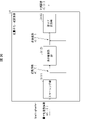
- FIG. 24 is a flow chart showing the flow of processing when non-separable conversion is performed by GPM.
- (S2200) Perform non-separable transformation using transformation matrix secTranMatrix[][]. Specifically, the processing from S2201 to S2204 described above may be performed.
- the addition unit 312 adds the predicted image of the block input from the predicted image generation unit 308 and the prediction error input from the inverse quantization/inverse transform unit 311 for each pixel to generate a decoded image of the block.
- the adder 312 stores the decoded image of the block in the reference picture memory 306 and also outputs it to the loop filter 305 .
- FIG. 7 is a block diagram showing the configuration of the video encoding device 11 according to this embodiment.
- the video encoding device 11 includes a predicted image generation unit 101, a subtraction unit 102, a transformation/quantization unit 103, an inverse quantization/inverse transformation unit 105, an addition unit 106, a loop filter 107, a prediction parameter memory (prediction parameter storage unit , frame memory) 108, reference picture memory (reference image storage unit, frame memory) 109, coding parameter determination unit 110, parameter coding unit 111, prediction parameter derivation unit 120, and entropy coding unit 104.
- a prediction parameter memory prediction parameter storage unit , frame memory
- reference picture memory reference image storage unit, frame memory
- the predicted image generation unit 101 generates a predicted image for each CU.
- the predicted image generation unit 101 includes the already described inter predicted image generation unit 309 and intra predicted image generation unit, and the description thereof is omitted.
- the subtraction unit 102 subtracts the pixel values of the predicted image of the block input from the predicted image generation unit 101 from the pixel values of the image T to generate prediction errors.
- Subtraction section 102 outputs the prediction error to transform/quantization section 103 .
- the transform/quantization unit 103 calculates transform coefficients by frequency transforming the prediction error input from the subtraction unit 102, and derives quantized transform coefficients by quantization.
- the transform/quantization unit 103 outputs the quantized transform coefficients to the parameter coding unit 111 and the inverse quantization/inverse transform unit 105 .
- the inverse quantization/inverse transform unit 105 is the same as the inverse quantization/inverse transform unit 311 in the moving image decoding device 31, and description thereof is omitted.
- the calculated prediction error is output to addition section 106 .
- the parameter encoding unit 111 includes a header encoding unit 1110, a CT information encoding unit 1111, and a CU encoding unit 1112 (prediction mode encoding unit).
- CU encoding section 1112 further comprises TU encoding section 1114 . The general operation of each module will be described below.
- a header encoding unit 1110 performs encoding processing of parameters such as header information, division information, prediction information, and quantized transform coefficients.
- a CT information encoding unit 1111 encodes QT, MT (BT, TT) division information and the like.
- a CU encoding unit 1112 encodes CU information, prediction information, division information, and the like.
- the TU encoding unit 1114 encodes the QP update information and the quantized prediction error when the TU contains the prediction error.
- the CT information encoding unit 1111 and the CU encoding unit 1112 parameter-encode syntax elements such as inter prediction parameters (predMode, merge_flag, merge_idx, inter_pred_idc, refIdxLX, mvp_LX_idx, mvdLX), intra prediction parameters, and quantized transform coefficients.
- inter prediction parameters predMode, merge_flag, merge_idx, inter_pred_idc, refIdxLX, mvp_LX_idx, mvdLX
- intra prediction parameters e.g., intra prediction parameters supplied to section 111.
- the entropy coding unit 104 receives input from the parameter coding unit 111 of the quantized transform coefficients and coding parameters (division information, prediction parameters). The entropy encoding unit 104 entropy-encodes these to generate and output an encoded stream Te.
- the prediction parameter derivation unit 120 is means including the inter prediction parameter encoding unit 112 and the intra prediction parameter encoding unit, and derives intra prediction parameters and intra prediction parameters from the parameters input from the encoding parameter determination unit 110.
- the derived intra prediction parameters and intra prediction parameters are output to parameter coding section 111 .
- Inter prediction parameter encoding section 112 is configured including parameter encoding control section 1121 and inter prediction parameter derivation section 303, as shown in FIG.
- the inter-prediction parameter deriving unit 303 has a configuration common to that of the video decoding device.
- Parameter encoding control section 1121 includes merge index derivation section 11211 and vector candidate index derivation section 11212 .
- the merge index derivation unit 11211 derives merge candidates and the like, and outputs them to the inter prediction parameter derivation unit 303.
- Vector candidate index derivation section 11212 derives vector prediction candidates and the like, and outputs them to inter prediction parameter derivation section 303 and parameter coding section 111 .
- the intra prediction parameter encoding unit includes a parameter encoding control unit and an intra prediction parameter derivation unit.
- the intra-prediction parameter deriving unit has a configuration common to that of the video decoding device.
- the inputs to the inter-prediction parameter derivation unit 303 and the intra-prediction parameter derivation unit are the coding parameter determination unit 110 and the prediction parameter memory 108, and are output to the parameter coding unit 111.
- the addition unit 106 adds pixel values of the prediction block input from the prediction image generation unit 101 and prediction errors input from the inverse quantization/inverse transformation unit 105 for each pixel to generate a decoded image.
- the addition unit 106 stores the generated decoded image in the reference picture memory 109 .
- a loop filter 107 applies a deblocking filter, SAO, and ALF to the decoded image generated by the addition unit 106.
- the prediction parameter memory 108 stores the prediction parameters generated by the coding parameter determination unit 110 in predetermined positions for each current picture and CU.
- the reference picture memory 109 stores the decoded image generated by the loop filter 107 in a predetermined position for each target picture and CU.
- the coding parameter determination unit 110 selects one set from a plurality of sets of coding parameters.
- the coding parameter is the above-described QT, BT or TT division information, prediction parameters, or parameters to be coded generated in relation to these.
- the predicted image generating unit 101 generates predicted images using these coding parameters.
- the coding parameter determination unit 110 calculates an RD cost value indicating the magnitude of the information amount and the coding error for each of the multiple sets.
- the RD cost value is, for example, the sum of the code amount and the value obtained by multiplying the squared error by the coefficient ⁇ .
- the code amount is the information amount of the encoded stream Te obtained by entropy-encoding the quantization error and encoding parameters.
- the squared error is the sum of squares of the prediction errors calculated in subtraction section 102 .
- the coefficient ⁇ is a preset real number greater than zero. Coding parameter determination section 110 selects a set of coding parameters that minimizes the calculated cost value. Coding parameter determination section 110 outputs the determined coding parameters to parameter coding section 111 and prediction parameter derivation section 120 .
- a program for realizing this control function may be recorded in a computer-readable recording medium, and the program recorded in this recording medium may be read into a computer system and executed.
- the “computer system” here is a computer system built into either the moving image encoding device 11 or the moving image decoding device 31, and includes hardware such as an OS and peripheral devices.
- the term "computer-readable recording medium” refers to portable media such as flexible discs, magneto-optical discs, ROMs, and CD-ROMs, and storage devices such as hard disks built into computer systems.
- “computer-readable recording medium” means a medium that dynamically stores a program for a short period of time, such as a communication line for transmitting a program via a network such as the Internet or a communication line such as a telephone line. In that case, it may also include a memory that holds the program for a certain period of time, such as a volatile memory inside a computer system that serves as a server or client. Further, the program may be for realizing part of the functions described above, or may be capable of realizing the functions described above in combination with a program already recorded in the computer system.
- part or all of the video encoding device 11 and the video decoding device 31 in the above-described embodiments may be implemented as an integrated circuit such as LSI (Large Scale Integration).
- LSI Large Scale Integration
- Each functional block of the moving image encoding device 11 and the moving image decoding device 31 may be processorized individually, or may be partially or wholly integrated and processorized.
- the method of circuit integration is not limited to LSI, but may be realized by a dedicated circuit or a general-purpose processor.
- an integrated circuit based on this technology may be used.
- Embodiments of the present invention are preferably applied to a moving image decoding device that decodes encoded image data and a moving image encoding device that generates encoded image data. be able to. Also, the present invention can be preferably applied to the data structure of encoded data generated by a video encoding device and referenced by a video decoding device.
- Image decoder 301 Entropy Decoder 302 Parameter decoder 303 Inter prediction parameter derivation unit 30377 GPM predictor 305, 107 loop filter 306, 109 Reference picture memory 307, 108 prediction parameter memory 308, 101 Predictive image generator 309 Inter prediction image generator 30952 GPM Synthesizer 311, 105 Inverse quantization/inverse transform section 312, 106 adder 11 Image encoding device 102 Subtractor 103 Transform/Quantization Unit 104 Entropy Encoder 110 Encoding parameter determination unit 111 Parameter encoder 112 Inter prediction parameter coding unit 120 Prediction parameter derivation unit
Landscapes
- Engineering & Computer Science (AREA)
- Multimedia (AREA)
- Signal Processing (AREA)
- Physics & Mathematics (AREA)
- Discrete Mathematics (AREA)
- General Physics & Mathematics (AREA)
- Compression Or Coding Systems Of Tv Signals (AREA)
Priority Applications (2)
| Application Number | Priority Date | Filing Date | Title |
|---|---|---|---|
| US18/564,463 US12335528B2 (en) | 2021-05-31 | 2022-03-24 | Video decoding apparatus and video coding apparatus |
| JP2023525432A JP7809108B2 (ja) | 2021-05-31 | 2022-03-24 | 動画像復号装置および動画像符号化装置 |
Applications Claiming Priority (2)
| Application Number | Priority Date | Filing Date | Title |
|---|---|---|---|
| JP2021091071 | 2021-05-31 | ||
| JP2021-091071 | 2021-05-31 |
Publications (1)
| Publication Number | Publication Date |
|---|---|
| WO2022254899A1 true WO2022254899A1 (ja) | 2022-12-08 |
Family
ID=84323019
Family Applications (1)
| Application Number | Title | Priority Date | Filing Date |
|---|---|---|---|
| PCT/JP2022/013833 Ceased WO2022254899A1 (ja) | 2021-05-31 | 2022-03-24 | 動画像復号装置および動画像符号化装置 |
Country Status (3)
| Country | Link |
|---|---|
| US (1) | US12335528B2 (https=) |
| JP (1) | JP7809108B2 (https=) |
| WO (1) | WO2022254899A1 (https=) |
Cited By (2)
| Publication number | Priority date | Publication date | Assignee | Title |
|---|---|---|---|---|
| WO2023112648A1 (ja) * | 2021-12-14 | 2023-06-22 | シャープ株式会社 | 動画像復号装置および動画像符号化装置 |
| WO2025252126A1 (en) * | 2024-06-04 | 2025-12-11 | Douyin Vision Co., Ltd. | Method, apparatus, and medium for video processing |
Families Citing this family (1)
| Publication number | Priority date | Publication date | Assignee | Title |
|---|---|---|---|---|
| US12513332B2 (en) * | 2022-07-05 | 2025-12-30 | Qualcomm Incorporated | Non-separable transform for inter-coded blocks |
Family Cites Families (7)
| Publication number | Priority date | Publication date | Assignee | Title |
|---|---|---|---|---|
| RU2722394C1 (ru) * | 2017-03-21 | 2020-05-29 | ЭлДжи ЭЛЕКТРОНИКС ИНК. | Способ преобразования в системе кодирования изображений и устройство для его осуществления |
| RU2768956C1 (ru) * | 2018-09-28 | 2022-03-25 | ДжейВиСиКЕНВУД Корпорейшн | Устройство декодирования изображения, способ декодирования изображения, устройство кодирования изображения и способ кодирования изображения |
| JP7537879B2 (ja) * | 2019-02-12 | 2024-08-21 | 日本放送協会 | イントラ予測装置、画像符号化装置、画像復号装置、及びプログラム |
| US20200344486A1 (en) * | 2019-04-26 | 2020-10-29 | Qualcomm Incorporated | Size constraint for triangular prediction unit mode |
| US11463693B2 (en) * | 2019-08-30 | 2022-10-04 | Qualcomm Incorporated | Geometric partition mode with harmonized motion field storage and motion compensation |
| EP4022902A4 (en) * | 2019-09-25 | 2022-11-23 | Huawei Technologies Co., Ltd. | HARMONIC TRIANGLE CONVERSION MODE WITH WEIGHTED PREDICTION |
| US11272179B2 (en) * | 2019-11-22 | 2022-03-08 | FG Innovation Company Limited | Device and method for coding video data |
-
2022
- 2022-03-24 JP JP2023525432A patent/JP7809108B2/ja active Active
- 2022-03-24 US US18/564,463 patent/US12335528B2/en active Active
- 2022-03-24 WO PCT/JP2022/013833 patent/WO2022254899A1/ja not_active Ceased
Non-Patent Citations (4)
| Title |
|---|
| "Versatile video coding; H.266 (08/20)", ITU-T STANDARD H.266, INTERNATIONAL TELECOMMUNICATION UNION, GENEVA ; CH, no. H.266 (08/20), 29 August 2020 (2020-08-29), Geneva ; CH, pages 1 - 516, XP044332656 * |
| MOONMO KOO , JAEHYUN LIM , MEHDI SALEHIFAR , SEUNG HWAN KIM: "CE6: Reduced Secondary Transform (RST) (CE6-3.1)", 14. JVET MEETING; 20190319 - 20190327; GENEVA; (THE JOINT VIDEO EXPLORATION TEAM OF ISO/IEC JTC1/SC29/WG11 AND ITU-T SG.16 ), no. JVET-N0193, 12 March 2019 (2019-03-12), pages 1 - 16, XP030202676 * |
| R. SJöBERG (ERICSSON), S. DESHPANDE, M. M. HANNUKSELA, R. SKUPIN, Y.-K. WANG, S. WENGER, H. YU: "JVET AHG report: High-level syntax (AHG17)", 14. JVET MEETING; 20190319 - 20190327; GENEVA; (THE JOINT VIDEO EXPLORATION TEAM OF ISO/IEC JTC1/SC29/WG11 AND ITU-T SG.16 ), 19 March 2019 (2019-03-19), XP030203564 * |
| R.-L. LIAO (ALIBABA-INC), Y. YE (ALIBABA-INC), J. CHEN (ALIBABA): "Non-CE4: Simplification of triangle partition and SBT combination", 14. JVET MEETING; 20190319 - 20190327; GENEVA; (THE JOINT VIDEO EXPLORATION TEAM OF ISO/IEC JTC1/SC29/WG11 AND ITU-T SG.16 ), 13 March 2019 (2019-03-13), XP030203129 * |
Cited By (3)
| Publication number | Priority date | Publication date | Assignee | Title |
|---|---|---|---|---|
| WO2023112648A1 (ja) * | 2021-12-14 | 2023-06-22 | シャープ株式会社 | 動画像復号装置および動画像符号化装置 |
| US12532028B2 (en) | 2021-12-14 | 2026-01-20 | Sharp Kabushiki Kaisha | Video decoding apparatus and video coding apparatus |
| WO2025252126A1 (en) * | 2024-06-04 | 2025-12-11 | Douyin Vision Co., Ltd. | Method, apparatus, and medium for video processing |
Also Published As
| Publication number | Publication date |
|---|---|
| US20240251105A1 (en) | 2024-07-25 |
| JP7809108B2 (ja) | 2026-01-30 |
| US12335528B2 (en) | 2025-06-17 |
| JPWO2022254899A1 (https=) | 2022-12-08 |
Similar Documents
| Publication | Publication Date | Title |
|---|---|---|
| US12120294B2 (en) | Method of encoding/decoding video signal using intra prediction and apparatus therefor | |
| KR101552632B1 (ko) | 예측 단위의 파티션 모드에 기초한 계수 스캔 방법 및 장치 | |
| KR102691340B1 (ko) | 비디오 신호 처리 방법 및 장치 | |
| KR102596896B1 (ko) | 비디오 신호 처리 방법 및 장치 | |
| JP7846554B2 (ja) | 動画像符号化装置、動画像復号装置および集積回路 | |
| JP7809108B2 (ja) | 動画像復号装置および動画像符号化装置 | |
| WO2020032049A1 (ja) | 動画像復号装置、および動画像符号化装置 | |
| KR20240037137A (ko) | 동화상 복호 장치 및 동화상 부호화 장치 | |
| JP2024047921A (ja) | 画像復号装置 | |
| WO2023090198A1 (ja) | 動画像符号化装置、動画像復号装置 | |
| WO2023112648A1 (ja) | 動画像復号装置および動画像符号化装置 | |
| JP2023103544A (ja) | 動画像復号装置 | |
| JP7735065B2 (ja) | 画像復号装置および画像符号化装置 | |
| WO2023100970A1 (ja) | 動画像復号装置および動画像符号化装置 | |
| US20250168405A1 (en) | Video decoding apparatus and video coding apparatus | |
| JP2024047922A (ja) | 画像復号装置および画像符号化装置 | |
| JP7817802B2 (ja) | 動画像復号装置および動画像符号化装置 | |
| JP7783715B2 (ja) | 動画像復号装置および動画像符号化装置 | |
| WO2025182198A1 (ja) | 動画像復号装置および動画像符号化装置 | |
| US20260012594A1 (en) | Video coding apparatus and video decoding apparatus | |
| JP2024006995A (ja) | 動画像復号装置および動画像符号化装置 | |
| WO2025069840A1 (ja) | 動画像復号装置および動画像符号化装置 | |
| WO2025187142A1 (ja) | 動画像復号装置および動画像符号化装置 | |
| JP2024092440A (ja) | 動画像符号化装置、復号装置 | |
| JP2023003481A (ja) | 画像復号装置および画像符号化装置 |
Legal Events
| Date | Code | Title | Description |
|---|---|---|---|
| 121 | Ep: the epo has been informed by wipo that ep was designated in this application |
Ref document number: 22815656 Country of ref document: EP Kind code of ref document: A1 |
|
| WWE | Wipo information: entry into national phase |
Ref document number: 2023525432 Country of ref document: JP |
|
| WWE | Wipo information: entry into national phase |
Ref document number: 18564463 Country of ref document: US |
|
| NENP | Non-entry into the national phase |
Ref country code: DE |
|
| 122 | Ep: pct application non-entry in european phase |
Ref document number: 22815656 Country of ref document: EP Kind code of ref document: A1 |
|
| WWG | Wipo information: grant in national office |
Ref document number: 18564463 Country of ref document: US |