WO2022254899A1 - 動画像復号装置および動画像符号化装置 - Google Patents
動画像復号装置および動画像符号化装置 Download PDFInfo
- Publication number
- WO2022254899A1 WO2022254899A1 PCT/JP2022/013833 JP2022013833W WO2022254899A1 WO 2022254899 A1 WO2022254899 A1 WO 2022254899A1 JP 2022013833 W JP2022013833 W JP 2022013833W WO 2022254899 A1 WO2022254899 A1 WO 2022254899A1
- Authority
- WO
- WIPO (PCT)
- Prior art keywords
- prediction
- gpm
- unit
- mode
- transform
- Prior art date
Links
- 238000005192 partition Methods 0.000 claims abstract description 15
- 239000011159 matrix material Substances 0.000 claims description 40
- 238000009795 derivation Methods 0.000 description 56
- 230000009466 transformation Effects 0.000 description 55
- 238000012545 processing Methods 0.000 description 53
- 239000013598 vector Substances 0.000 description 38
- 238000013139 quantization Methods 0.000 description 37
- 238000000034 method Methods 0.000 description 24
- 238000010586 diagram Methods 0.000 description 19
- 230000002194 synthesizing effect Effects 0.000 description 18
- 238000006243 chemical reaction Methods 0.000 description 13
- 238000000638 solvent extraction Methods 0.000 description 12
- 208000034188 Stiff person spectrum disease Diseases 0.000 description 11
- 229920010524 Syndiotactic polystyrene Polymers 0.000 description 11
- 208000012112 ischiocoxopodopatellar syndrome Diseases 0.000 description 11
- 238000002490 spark plasma sintering Methods 0.000 description 11
- 230000006870 function Effects 0.000 description 9
- 229920000069 polyphenylene sulfide Polymers 0.000 description 9
- 230000015572 biosynthetic process Effects 0.000 description 7
- 230000008569 process Effects 0.000 description 7
- 238000003786 synthesis reaction Methods 0.000 description 7
- 230000005540 biological transmission Effects 0.000 description 4
- 238000004891 communication Methods 0.000 description 4
- 238000005516 engineering process Methods 0.000 description 4
- 230000002123 temporal effect Effects 0.000 description 4
- 241000209094 Oryza Species 0.000 description 3
- 235000007164 Oryza sativa Nutrition 0.000 description 3
- 230000003044 adaptive effect Effects 0.000 description 3
- 230000000694 effects Effects 0.000 description 3
- 235000009566 rice Nutrition 0.000 description 3
- 238000000926 separation method Methods 0.000 description 3
- 230000001131 transforming effect Effects 0.000 description 3
- 230000007704 transition Effects 0.000 description 3
- 238000012937 correction Methods 0.000 description 2
- 238000005401 electroluminescence Methods 0.000 description 2
- 230000010354 integration Effects 0.000 description 2
- OSWPMRLSEDHDFF-UHFFFAOYSA-N methyl salicylate Chemical compound COC(=O)C1=CC=CC=C1O OSWPMRLSEDHDFF-UHFFFAOYSA-N 0.000 description 2
- 238000010606 normalization Methods 0.000 description 2
- 238000000844 transformation Methods 0.000 description 2
- PXFBZOLANLWPMH-UHFFFAOYSA-N 16-Epiaffinine Natural products C1C(C2=CC=CC=C2N2)=C2C(=O)CC2C(=CC)CN(C)C1C2CO PXFBZOLANLWPMH-UHFFFAOYSA-N 0.000 description 1
- 241001025261 Neoraja caerulea Species 0.000 description 1
- 230000006978 adaptation Effects 0.000 description 1
- 230000008901 benefit Effects 0.000 description 1
- 239000012141 concentrate Substances 0.000 description 1
- 238000013461 design Methods 0.000 description 1
- 230000009977 dual effect Effects 0.000 description 1
- 239000004973 liquid crystal related substance Substances 0.000 description 1
- 238000004519 manufacturing process Methods 0.000 description 1
- 230000003287 optical effect Effects 0.000 description 1
- 230000002093 peripheral effect Effects 0.000 description 1
- 239000004065 semiconductor Substances 0.000 description 1
- 230000000153 supplemental effect Effects 0.000 description 1
Images


Classifications
-
- H—ELECTRICITY
- H04—ELECTRIC COMMUNICATION TECHNIQUE
- H04N—PICTORIAL COMMUNICATION, e.g. TELEVISION
- H04N19/00—Methods or arrangements for coding, decoding, compressing or decompressing digital video signals
- H04N19/10—Methods or arrangements for coding, decoding, compressing or decompressing digital video signals using adaptive coding
- H04N19/102—Methods or arrangements for coding, decoding, compressing or decompressing digital video signals using adaptive coding characterised by the element, parameter or selection affected or controlled by the adaptive coding
- H04N19/12—Selection from among a plurality of transforms or standards, e.g. selection between discrete cosine transform [DCT] and sub-band transform or selection between H.263 and H.264
-
- H—ELECTRICITY
- H04—ELECTRIC COMMUNICATION TECHNIQUE
- H04N—PICTORIAL COMMUNICATION, e.g. TELEVISION
- H04N19/00—Methods or arrangements for coding, decoding, compressing or decompressing digital video signals
- H04N19/10—Methods or arrangements for coding, decoding, compressing or decompressing digital video signals using adaptive coding
- H04N19/134—Methods or arrangements for coding, decoding, compressing or decompressing digital video signals using adaptive coding characterised by the element, parameter or criterion affecting or controlling the adaptive coding
- H04N19/157—Assigned coding mode, i.e. the coding mode being predefined or preselected to be further used for selection of another element or parameter
-
- H—ELECTRICITY
- H04—ELECTRIC COMMUNICATION TECHNIQUE
- H04N—PICTORIAL COMMUNICATION, e.g. TELEVISION
- H04N19/00—Methods or arrangements for coding, decoding, compressing or decompressing digital video signals
- H04N19/60—Methods or arrangements for coding, decoding, compressing or decompressing digital video signals using transform coding
- H04N19/61—Methods or arrangements for coding, decoding, compressing or decompressing digital video signals using transform coding in combination with predictive coding
-
- H—ELECTRICITY
- H04—ELECTRIC COMMUNICATION TECHNIQUE
- H04N—PICTORIAL COMMUNICATION, e.g. TELEVISION
- H04N19/00—Methods or arrangements for coding, decoding, compressing or decompressing digital video signals
- H04N19/70—Methods or arrangements for coding, decoding, compressing or decompressing digital video signals characterised by syntax aspects related to video coding, e.g. related to compression standards
Definitions
- Embodiments of the present invention relate to a video decoding device and a video encoding device.
- a moving image encoding device that generates encoded data by encoding a moving image and a moving image that generates a decoded image by decoding the encoded data in order to efficiently transmit or record the moving image An image decoding device is used.
- video encoding methods include H.264/AVC and HEVC (High-Efficiency Video Coding).
- the images (pictures) that make up the video are divided into slices obtained by dividing an image, and coding tree units (CTU: Coding Tree Units) obtained by dividing a slice. ), a coding unit obtained by dividing the coding tree unit (Coding Unit: CU)), and a transform unit obtained by dividing the coding unit (TU: Transform Unit), and encoded/decoded for each CU.
- CTU Coding Tree Units
- a predicted image is normally generated based on a locally decoded image obtained by encoding/decoding an input image, and the predicted image is generated from the input image (original image).
- the prediction error obtained by subtraction (sometimes called the "difference image” or “residual image”) is encoded.
- Inter-prediction and intra-prediction are methods for generating predicted images.
- Non-Patent Document 1 discloses a GPM (Geometric partition mode) mode in which a target block is divided into shapes other than rectangles and different inter predictions are performed for each region. By dividing the target block into non-rectangular shapes in this way, even complex textures can be predicted more accurately, and coding efficiency is improved.
- Non-Patent Document 1 discloses an image coding apparatus that performs non-separate transform in order to further concentrate coefficients obtained by separating and transforming prediction errors in a low frequency region for each transform unit.
- Non-Patent Document 1 non-separable transform and inverse non-separable transform techniques that are effective for directional prediction residuals are applied only to intra-predicted blocks, and are not applied to inter-predicted blocks that have many diagonal directions. do not have.
- An object of the present invention is to provide a moving image decoding device, a moving image encoding device, and related technology that can more preferably apply inverse non-separable transform.
- a video decoding device includes a prediction unit that derives a predicted image using a weight parameter derived from an angle variable, and a non-separable transform that performs non-separable transform.
- the separable transform unit derives a non-separable transform set number (lfnstTrSetId) from GPM partition information (merge_gpm_partition_idx) when the inter prediction mode is the GPM mode.
- a video coding apparatus includes a prediction unit that derives a predicted image using a weight parameter derived from an angle variable, and a non-separable transform unit that performs non-separable transform.
- the separable transform unit derives a non-separable transform set number (lfnstTrSetId) from GPM partition information (merge_gpm_partition_idx) when the inter prediction mode is the GPM mode.
- FIG. 1 is a schematic diagram showing the configuration of an image transmission system according to this embodiment
- FIG. FIG. 3 is a diagram showing the hierarchical structure of data in an encoded stream
- 1 is a schematic diagram showing the configuration of a video decoding device
- FIG. 4 is a flowchart for explaining schematic operations of a video decoding device
- FIG. 4 is a schematic diagram showing the configuration of an inter-prediction parameter deriving unit
- It is a schematic diagram which shows the structure of an inter prediction image production
- 1 is a block diagram showing the configuration of a video encoding device
- FIG. FIG. 4 is a schematic diagram showing the configuration of an inter-prediction parameter encoding unit
- FIG. 4 is a diagram for explaining GPM prediction
- FIG. 4 is a syntax diagram illustrating coding parameters for GPM prediction
- FIG. 10 is a diagram showing the structure of a table showing the correspondence between merge_gpm_partition_idx and angleIdx and distanceIdx in GPM prediction.
- FIG. 10 is a diagram showing the structure of a table showing the correspondence between idx and DisLut[idx] used in weighting factor derivation processing and motion vector storage processing in GPM prediction; 10 is a flowchart showing the flow of GPM prediction processing;
- intra prediction mode it is a table used for transform matrix selection of non-separable transform.
- In GPM mode it is a table used for transform matrix selection of non-separable transform.
- GPM mode it is a table used for transform matrix selection of non-separable transform.
- GPM mode it is a table used for transform matrix selection of non-separable transform.
- GPM mode it is a table used for transform matrix selection of non-separable transform.
- GPM mode it is a table used for transform matrix selection of non-separable transform.
- 2 is a functional block diagram showing a configuration example of an inverse quantization/inverse transform unit;
- FIG. It is an example of a syntax table showing coding parameters for GPM non-separable transform.
- 4 is a flow chart showing the flow of processing when non-separable conversion is performed by GPM;
- FIG. 1 is a schematic diagram showing the configuration of an image transmission system 1 according to this embodiment.
- the image transmission system 1 is a system that transmits an encoded stream obtained by encoding a target image, decodes the transmitted encoded stream, and displays the image.
- the image transmission system 1 includes a moving image coding device (image coding device) 11, a network 21, a moving image decoding device (image decoding device) 31, and a moving image display device (image display device) 41. .
- An image T is input to the video encoding device 11 .
- the network 21 transmits the encoded stream Te generated by the video encoding device 11 to the video decoding device 31.
- the network 21 is the Internet, a Wide Area Network (WAN), a Local Area Network (LAN), or a combination thereof.
- the network 21 is not necessarily a two-way communication network, and may be a one-way communication network that transmits broadcast waves such as terrestrial digital broadcasting and satellite broadcasting.
- the network 21 may be replaced by a storage medium such as a DVD (Digital Versatile Disc: registered trademark) or a BD (Blue-ray Disc: registered trademark) that records the encoded stream Te.
- the video decoding device 31 decodes each of the encoded streams Te transmitted by the network 21 and generates one or more decoded decoded images Td.
- the moving image display device 41 displays all or part of one or more decoded images Td generated by the moving image decoding device 31.
- the moving image display device 41 includes, for example, a display device such as a liquid crystal display or an organic EL (Electro-luminescence) display.
- the form of the display includes stationary, mobile, HMD, and the like.
- the moving image decoding device 31 has high processing power, it displays an image with high image quality, and when it has only lower processing power, it displays an image that does not require high processing power and display power. .
- x?y:z is a ternary operator that takes y if x is true (other than 0) and z if x is false (0).
- abs(a) is a function that returns the absolute value of a.
- Int(a) is a function that returns the integer value of a.
- floor(a) is a function that returns the largest integer less than or equal to a.
- ceil(a) is a function that returns the smallest integer greater than or equal to a.
- a/d represents the division of a by d (truncated after the decimal point).
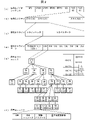
- Fig. 2 is a diagram showing the hierarchical structure of data in the encoded stream Te.
- the encoded stream Te illustratively includes a sequence and a plurality of pictures that constitute the sequence.
- (a) to (f) of FIG. 2 respectively show a coded video sequence that defines a sequence SEQ, a coded picture that defines a picture PICT, a coded slice that defines a slice S, and a coded slice that defines slice data.
- FIG. 3 is a diagram showing data, a coding tree unit included in the coded slice data, and a coding unit included in the coding tree unit;
- the encoded video sequence defines a set of data that the video decoding device 31 refers to in order to decode the sequence SEQ to be processed.
- Sequence SEQ as shown in Figure 2, consists of Video Parameter Set, Sequence Parameter Set SPS, Picture Parameter Set PPS, Adaptation Parameter Set (APS), Picture PICT, and Supplemental Enhancement Information (SEI).
- a video parameter set VPS is a set of coding parameters common to multiple video images, multiple layers included in the video image, and coding parameters related to individual layers. Sets are defined.
- the sequence parameter set SPS defines a set of coding parameters that the video decoding device 31 refers to in order to decode the target sequence. For example, the width and height of the picture are defined. A plurality of SPSs may exist. In that case, one of a plurality of SPSs is selected from the PPS.
- the picture parameter set PPS defines a set of coding parameters that the video decoding device 31 refers to in order to decode each picture in the target sequence. For example, it includes a quantization width reference value (pic_init_qp_minus26) used for picture decoding and a flag (weighted_pred_flag) indicating application of weighted prediction.
- a plurality of PPSs may exist. In that case, one of a plurality of PPSs is selected from each picture in the target sequence.
- the encoded picture defines a set of data that the video decoding device 31 refers to in order to decode the picture PICT to be processed.
- a picture PICT includes slices 0 to NS-1 (NS is the total number of slices included in the picture PICT), as shown in FIG.
- the encoded slice defines a set of data that the video decoding device 31 refers to in order to decode the slice S to be processed.
- a slice includes a slice header and slice data, as shown in FIG.
- the slice header contains a group of coding parameters that the video decoding device 31 refers to in order to determine the decoding method for the target slice.
- Slice type designation information (slice_type) that designates a slice type is an example of a coding parameter included in a slice header.
- Slice types that can be specified by the slice type specifying information include (1) I slices that use only intra prediction during encoding, (2) P slices that use unidirectional prediction or intra prediction during encoding, (3) B slices using uni-prediction, bi-prediction, or intra-prediction during encoding.
- inter prediction is not limited to uni-prediction and bi-prediction, and a predicted image may be generated using more reference pictures.
- P and B slices they refer to slices containing blocks for which inter prediction can be used.
- the slice header may contain a reference (pic_parameter_set_id) to the picture parameter set PPS.
- the encoded slice data defines a set of data that the video decoding device 31 refers to in order to decode slice data to be processed.
- the slice data includes CTU, as shown in FIG. 2(d).
- a CTU is a fixed-size (for example, 64x64) block that forms a slice, and is also called a largest coding unit (LCU).
- FIG. 2 defines a set of data that the video decoding device 31 refers to in order to decode the CTU to be processed.
- CTU uses recursive quad tree partitioning (QT (Quad Tree) partitioning), binary tree partitioning (BT (Binary Tree) partitioning), or ternary tree partitioning (TT (Ternary Tree) partitioning) to perform coding processing. It is divided into coding units CU, which are basic units. BT partitioning and TT partitioning are collectively called multi-tree partitioning (MT (Multi Tree) partitioning).
- MT Multi Tree partitioning
- a node of a tree structure obtained by recursive quadtree partitioning is called a coding node.
- Intermediate nodes of quadtrees, binary trees, and ternary trees are coding nodes, and the CTU itself is defined as the top-level coding node.
- CT includes, as CT information, a CU split flag (split_cu_flag) indicating whether or not to perform CT splitting, a QT split flag (qt_split_cu_flag) indicating whether or not to perform QT splitting, and an MT splitting direction indicating the splitting direction of MT splitting ( mtt_split_cu_vertical_flag), including MT split type (mtt_split_cu_binary_flag) indicating the split type of the MT split.
- split_cu_flag, qt_split_cu_flag, mtt_split_cu_vertical_flag and mtt_split_cu_binary_flag are transmitted for each encoding node.
- Different trees may be used for luminance and color difference.
- the type of tree is indicated by treeType.
- treeType DUAL_TREE_LUMA for luminance
- treeType DUAL_TREE_CHROMA for chrominance.
- FIG. 2 defines a set of data that the video decoding device 31 refers to in order to decode the encoding unit to be processed.
- a CU is composed of a CU header CUH, prediction parameters, transform parameters, quantized transform coefficients, and the like.
- a prediction mode and the like are defined in the CU header.
- Prediction processing may be performed in units of CUs or in units of sub-CUs, which are subdivided into CUs. If the CU and sub-CU sizes are equal, there is one sub-CU in the CU. If the CU is larger than the sub-CU size, the CU is split into sub-CUs. For example, if the CU is 8x8 and the sub-CU is 4x4, the CU is divided into 4 sub-CUs consisting of 2 horizontal divisions and 2 vertical divisions.
- prediction mode The types of prediction (prediction mode) are intra prediction (MODE_INTRA), inter prediction (MODE_INTER), and intra block copy (MODE_IBC). Intra prediction is prediction within the same picture, and inter prediction is prediction processing performed between different pictures (for example, between display times, between layer images).
- the transform/quantization process is performed in CU units, but the quantized transform coefficients may be entropy coded in subblock units such as 4x4.
- prediction parameter A predicted image is derived from the prediction parameters associated with the block.
- the prediction parameters include prediction parameters for intra prediction and inter prediction.
- the intra prediction parameters are composed of a luminance prediction mode IntraPredModeY (predModeIntra) and a color difference prediction mode IntraPredModeC.
- IntraPredModeY predModeIntra
- IntraPredModeC color difference prediction mode
- intra prediction modes for example, planar prediction (0), DC prediction (1), Angular prediction (2-66).
- the inter prediction parameters are composed of prediction list usage flags predFlagL0 and predFlagL1, reference picture indices refIdxL0 and refIdxL1, and motion vectors mvL0 and mvL1.
- predFlagL0 and predFlagL1 are flags indicating whether or not reference picture lists (L0 list, L1 list) are used, and when the value is 1, the corresponding reference picture list is used.
- flag when the term "flag indicating whether or not it is XX" is used, when the flag is other than 0 (for example, 1), it is XX, and 0 is not XX. Treat 1 as true and 0 as false (same below). However, in actual devices and methods, other values can be used as true and false values.
- Syntax elements for deriving inter prediction parameters include, for example, merge flag merge_flag (general_merge_flag), merge index merge_idx, merge_subblock_flag, regulare_merge_flag, and intra inter flag ciip_flag that indicate whether to use subblock-based inter prediction such as affine mode.
- GPM_flag indicating whether to use GPM mode (Geometric partitioning merge mode), merge_gpm_partition_idx indicating the partition shape of GPM mode, merge_gpm_idx0, merge_gpm_idx1 indicating the GPM merge index, inter prediction identifier inter_pred_idc for selecting reference pictures used in AMVP mode , a reference picture index refIdxLX, a predicted vector index mvp_LX_idx for deriving a motion vector, a difference vector mvdLX, and a motion vector precision mode amvr_mode.
- a reference picture list is a list of reference pictures stored in the reference picture memory 306 .
- merge prediction and AMVP prediction There are merge prediction (merge) mode (merge mode) and AMVP (Advanced Motion Vector Prediction, Adaptive Motion Vector Prediction) mode for the prediction parameter decoding (encoding) method, and merge_flag is a flag to identify these.
- the merge mode is a prediction mode that omits part or all of the motion vector difference, and predicts already processed neighboring blocks without including the prediction list usage flag predFlagLX, the reference picture index refIdxLX, and the motion vector mvLX in the encoded data. This mode is derived from parameters and the like.
- AMVP mode is a mode in which inter_pred_idc, refIdxLX, and mvLX are included in encoded data.
- mvLX is encoded as mvp_LX_idx that identifies the prediction vector mvpLX and the difference vector mvdLX.
- general merge mode the generic name of the prediction mode which abbreviate
- general_merge_flag the generic name of the prediction mode which abbreviate
- regular_merge_flag may be transmitted, and if regular_merge_flag is 1, normal merge mode or MMVD may be selected, otherwise CIIP mode or GPM mode may be selected.
- inter_pred_idc is a value that indicates the type and number of reference pictures, and takes one of PRED_L0, PRED_L1, and PRED_BI.
- PRED_L0 and PRED_L1 indicate uni-prediction using one reference picture managed by the L0 list and L1 list, respectively.
- PRED_BI indicates bi-prediction using two reference pictures managed by the L0 list and L1 list.
- merge_idx is an index that indicates which prediction parameter is to be used as the prediction parameter for the target block among the prediction parameter candidates (merge candidates) derived from the blocks for which processing has been completed.
- (motion vector) mvLX indicates the amount of shift between blocks on two different pictures.
- a prediction vector and a difference vector for mvLX are called mvpLX and mvdLX, respectively.
- inter_pred_idc Inter prediction identifier inter_pred_idc and prediction list usage flag predFlagLX
- inter_pred_idc The relationships between inter_pred_idc, predFlagL0, and predFlagL1 are as follows, and can be mutually converted.
- the inter-prediction parameter may use a prediction list usage flag or an inter-prediction identifier. Also, the judgment using the prediction list usage flag may be replaced with the judgment using the inter-prediction identifier. Conversely, the determination using the inter-prediction identifier may be replaced with the determination using the prediction list usage flag.
- the video decoding device 31 includes an entropy decoding unit 301, a parameter decoding unit (prediction image decoding device) 302, a loop filter 305, a reference picture memory 306, a prediction parameter memory 307, a prediction image generation unit (prediction image generation device) 308, an inverse It includes a quantization/inverse transformation unit 311, an addition unit 312, and a prediction parameter derivation unit (not shown).
- the moving image decoding device 31 may have a configuration in which the loop filter 305 is not included in accordance with the moving image encoding device 11 described later.
- the parameter decoding unit 302 further includes a header decoding unit 3020, a CT information decoding unit 3021, and a CU decoding unit 3022 (prediction mode decoding unit), and the CU decoding unit 3022 further includes a TU decoding unit 3024. These may be collectively called a decoding module.
- Header decoding section 3020 decodes parameter set information such as VPS, SPS, PPS, and APS, and slice headers (slice information) from encoded data.
- CT information decoding section 3021 decodes CT from encoded data.
- a CU decoding unit 3022 decodes a CU from encoded data.
- TU decoding section 3024 decodes QP update information (quantization correction value) and quantization prediction error (residual_coding) from encoded data when prediction error is included in TU.
- the header decoding unit 3020 decodes the flag sps_lfnst_enabled_flag indicating whether or not to use the non-separate transform from the SPS. Also, when the sps_lfnst_enabled_flag is 1, the header decoding unit 3020 decodes the ph_lfnst_enabled_flag from the picture header (PH). Infer ph_lfnst_enabled_flag to 0 if ph_lfnst_enabled_flag does not appear.
- the value of sps_lfnst_enabled_flag may be set as the value of ph_lfnst_enabled_flag.
- the GPM non-separable transform in the present invention is the inverse non-separable transform (and non-separable transform) when inter prediction is in GPM mode.
- a method of deriving a non-separable transformation matrix or a set of transformation matrices from a GPM partition shape when adapted to an inter CU will be described below.
- Fig. 21 is an example of a syntax table showing coding parameters for GPM non-separable transform.
- the header decoding unit 3020 decodes the flag sps_gpm_lfnst_enabled_flag from the SPS.
- sps_gpm_lfnst_enabled_flag is a flag indicating whether to use GPM non-separable transform in the case of GPM prediction.
- header decoding section 3020 decodes sps_gpm_lfnst_enabled_flag.
- sps_gpm_enabled_flag is a flag indicating whether the GPM prediction mode is used in the target sequence.
- the TU decoding unit 3024 decodes the index mts_idx indicating the transform basis from the encoded data. Also, the TU decoding unit 3024 decodes the parameter lfnst_idx indicating whether non-separable transform is used and the transform basis from the encoded data. Specifically, the TU decoding unit 3024 decodes lfnst_idx when the width and height of the CU are 4 or more and the prediction mode is the intra prediction mode.
- the predicted image generation unit 308 includes an inter predicted image generation unit 309 (FIG. 6) and an intra predicted image generation unit 310.
- the prediction parameter derivation unit includes an inter prediction parameter derivation unit 303 (Fig. 5) and an intra prediction parameter derivation unit.
- CTU and CU as processing units
- processing may be performed in sub-CU units.
- CTU and CU may be read as blocks
- sub-CU may be read as sub-blocks
- processing may be performed in units of blocks or sub-blocks.
- the entropy decoding unit 301 performs entropy decoding on the encoded stream Te input from the outside to decode individual codes (syntax elements).
- syntax elements For entropy coding, a method of variable-length coding syntax elements using a context (probability model) adaptively selected according to the type of syntax elements and surrounding circumstances, a predetermined table, or There is a method of variable-length coding syntax elements using a formula.
- the entropy decoding unit 301 outputs the decoded code to the parameter decoding unit 302.
- the decoded codes are, for example, prediction modes predMode, merge_flag, merge_idx, inter_pred_idc, refIdxLX, mvp_LX_idx, mvdLX, amvr_mode, and the like. Control of which code is to be decoded is performed based on an instruction from parameter decoding section 302 .
- FIG. 4 is a flow chart for explaining a schematic operation of the video decoding device 31. As shown in FIG.
- the header decoding unit 3020 decodes parameter set information such as VPS, SPS, and PPS from the encoded data.
- the header decoding unit 3020 decodes the slice header (slice information) from the encoded data.
- the video decoding device 31 derives a decoded image of each CTU by repeating the processing from S1300 to S5000 for each CTU included in the target picture.
- the CT information decoding unit 3021 decodes the CTU from the encoded data.
- the CT information decoding unit 3021 decodes the CT from the encoded data.
- the CU decoding unit 3022 performs S1510 and S1520 to decode the CU from the encoded data.
- the CU decoding unit 3022 decodes CU information, prediction information, TU split flag split_transform_flag, CU residual flags cbf_cb, cbf_cr, cbf_luma, etc. from the encoded data.
- TU decoding section 3024 decodes quantized prediction error and transform index mts_idx from encoded data when prediction error is included in TU.
- the predicted image generation unit 308 generates a predicted image based on the prediction information for each block included in the target CU.
- the inverse quantization/inverse transform unit 311 executes inverse quantization/inverse transform processing for each TU included in the target CU.
- the addition unit 312 adds the predicted image supplied from the predicted image generation unit 308 and the prediction error supplied from the inverse quantization/inverse transform unit 311, thereby decoding the target CU. Generate an image.
- the loop filter 305 applies a loop filter such as a deblocking filter, SAO, and ALF to the decoded image to generate a decoded image.
- a loop filter such as a deblocking filter, SAO, and ALF
- the intra prediction parameter deriving unit Based on the code input from the entropy decoding unit 301, the intra prediction parameter deriving unit refers to the prediction parameters stored in the prediction parameter memory 307 and decodes the intra prediction parameters, for example, the intra prediction mode IntraPredMode.
- the intra prediction parameter derivation unit outputs the decoded intra prediction parameters to the prediction image generation unit 308 and stores them in the prediction parameter memory 307 .
- the intra prediction parameter derivation unit may derive different intra prediction modes for luminance and color difference.
- a loop filter 305 is a filter provided in the encoding loop, and is a filter that removes block distortion and ringing distortion and improves image quality.
- a loop filter 305 applies filters such as a deblocking filter, a sample adaptive offset (SAO), and an adaptive loop filter (ALF) to the decoded image of the CU generated by the addition unit 312 .
- filters such as a deblocking filter, a sample adaptive offset (SAO), and an adaptive loop filter (ALF) to the decoded image of the CU generated by the addition unit 312 .
- the reference picture memory 306 stores the decoded image of the CU generated by the adding unit 312 in a predetermined position for each target picture and target CU.
- the prediction parameter memory 307 stores prediction parameters in predetermined positions for each CTU or CU to be decoded. Specifically, the prediction parameter memory 307 stores the parameters decoded by the parameter decoding unit 302, the prediction mode predMode separated by the entropy decoding unit 301, and the like.
- a prediction mode predMode, prediction parameters, etc. are input to the prediction image generation unit 308 .
- the predicted image generation unit 308 reads a reference picture from the reference picture memory 306 .
- the predicted image generating unit 308 generates a predicted image of a block or sub-block using the prediction parameter and the read reference picture (reference picture block) in the prediction mode indicated by the prediction mode predMode.
- a reference picture block is a set of pixels on a reference picture (usually rectangular and therefore called a block), and is an area referred to for generating a prediction image.
- the intra-predicted image generating unit 310 refers to the read decoded pixel values and the prediction mode indicated by IntraPredMode to generate a predicted image of the target block.
- the intra prediction image generation unit 310 outputs the generated block prediction image to the addition unit 312 .
- Inter prediction parameter derivation section 303 derives inter prediction parameters by referring to prediction parameters stored in prediction parameter memory 307 based on syntax elements input from parameter decoding section 302 . Also, inter prediction parameters are output to inter prediction image generation section 309 and prediction parameter memory 307 .
- the inter-prediction parameter derivation unit 303 and its internal elements, the AMVP prediction parameter derivation unit 3032, the merge prediction parameter derivation unit 3036, the GPM prediction unit 30377, and the MV addition unit 3038, are common to the video encoding device and the video decoding device. Since these are means for deriving motion vectors, they may be collectively referred to as motion vector derivation units (motion vector derivation devices).
- GPM_Flag 1, that is, indicates the GPM prediction mode
- the GPM prediction unit 30377 derives GPM prediction parameters.
- merge_idx is derived and output to the merge prediction parameter derivation unit 3036.
- the AMVP prediction parameter derivation unit 3032 derives mvpLX from inter_pred_idc, refIdxLX or mvp_LX_idx.
- the MV adder 3038 adds the derived mvpLX and mvdLX to derive mvLX.
- the merge prediction parameter derivation unit 3036 includes a merge candidate derivation unit and a merge candidate selection unit.
- the merge candidates are configured including prediction parameters (predFlagLX, mvLX, refIdxLX) and stored in the merge candidate list.
- the merge candidates stored in the merge candidate list are assigned indices according to a predetermined rule.
- the merge candidate derivation unit derives merge candidates using the decoded adjacent block motion vectors and refIdxLX as they are.
- the merge candidate derivation unit may apply spatial merge candidate derivation processing, temporal merge candidate derivation processing, and the like, which will be described later.
- the merge candidate derivation unit reads the prediction parameters stored in the prediction parameter memory 307 according to a predetermined rule and sets them as merge candidates.
- the method of specifying the reference picture is, for example, all or part of the adjacent blocks within a predetermined range from the target block (for example, all or part of the blocks that touch the left A1, right B1, upper right B0, lower left A0, and upper left B2 of the target block, respectively).
- ) are prediction parameters for each of Call each merge candidate A1, B1, B0, A0, B2.
- A1, B1, B0, A0, B2 are each motion information derived from a block containing the following coordinates:
- the merge candidate derivation unit reads out the prediction parameters of the block C in the reference image including the lower right CBR of the target block or the center coordinates from the prediction parameter memory 307 and sets them as merge candidates Col. Store in candidate list mergeCandList[].
- mergeCandList[] The order of storing in mergeCandList[] is, for example, spatial merge candidate (B1, A1, B0, A0, B2), temporal merge candidate Col. Note that reference blocks that are not available (blocks are intra-predicted, etc.) are not stored in the merge candidate list.
- the merge candidate selection unit selects the merge candidate N indicated by merge_idx from among the merge candidates included in the merge candidate list using the following formula.
- N mergeCandList[merge_idx]
- N is a label indicating a merge candidate, such as A1, B1, B0, A0, B2, Col.
- the motion information of the merge candidate indicated by label N is indicated by (mvLXN[0], mvLXN[0]), predFlagLXN, and refIdxLXN.
- the merge candidate selection unit stores the inter prediction parameters of the selected merge candidates in the prediction parameter memory 307 and outputs them to the inter prediction image generation unit 309 .
- GPM prediction GPM prediction is explained.
- GPM prediction is prediction used in GPM mode, and generates a predicted image as two non-rectangular prediction units that divide the target CU by a line segment.
- FIG. 9(a) shows an example of a straight line segment.
- a straight line segment spanning the target CU is defined by an angle index angleIdx (angle variable) and a distance index distanceIdx (distance variable) shown in FIG. 9(b).
- angleIdx indicates the angle ⁇ between a vertical straight line and the straight line segment.
- distanceIdx indicates the distance ⁇ from the center of the target CU to the straight line segment.
- angleIdx is an integer value assigned to the angle of a straight line segment.
- 360 degrees when 360 degrees are roughly divided into 32, the values shown in FIG. 9(c) are assigned.
- 360 degrees are divided into 32 using square scales (coordinates) instead of perfectly equal division.
- 360 degrees may be divided into 64, and a finer angle index may be sent.
- GPM prediction In the prediction image generation of GPM prediction, two “rectangular” prediction images (temporary prediction images) containing non-rectangular prediction units are derived, and the above two rectangular regions are weighted according to the shape of the non-rectangular prediction unit. It may be derived by doing
- the motion compensation unit 3091 derives two temporary predicted images of the target CU, and the GPM synthesizing unit 30952 weights each pixel of the two temporary predicted images according to the position of the pixel to generate a predicted image. to derive This processing is called GPM synthesis processing. Processing other than prediction (eg transform (inverse transform) and quantization (inverse quantization)) is applied to the entire target CU.
- prediction eg transform (inverse transform) and quantization (inverse quantization)
- the GPM prediction unit 30377 derives prediction parameters for the two non-rectangular regions and supplies them to the inter prediction image generation unit 309.
- GPM prediction may be configured without bi-prediction for simplification of processing.
- inter-prediction parameters for unidirectional prediction are derived for non-rectangular regions.
- sps_gpm_enabled_flag is notified by SPS and indicates whether the GPM prediction mode is used in the target sequence. If sps_gpm_enabled_flag is 0, it indicates that GPM prediction mode is not used in the target sequence. When sps_gpm_enabled_flag is 1, it indicates that the GPM prediction mode is used in the target sequence.
- the GPM prediction mode in which the number of selectable split patterns (split types) is NumGPMFull (for example, 64) is used in the target sequence.
- sps_gpm_enabled_flag is not limited to SPS, and may be transmitted in PPS, picture header, or slice header.
- Fig. 10(b) is a diagram showing the syntax configuration notified in merge mode.
- the parameter decoding unit 302 decodes syntax elements in the encoded data, and the GPM prediction unit 30377 (inter prediction parameter derivation unit 303) derives GPM prediction parameters according to the following rules.
- sps_max_num_merge_cand_minus_max_num_gpm_cand is notified.
- sps_max_num_merge_cand_minus_max_num_gpm_cand is a parameter used to derive the maximum number of merge candidates for GPM prediction, MaxNumGpmMergeCand.
- the GPM prediction unit 30377 derives merge candidate MergeCand from 0 to the maximum number of merge prediction candidates MaxNumMergeCand-1.
- MaxNumGpmMergeCand is 3 or more
- MaxNumGpmMergeCand MaxNumMergeCand - sps_max_num_merge_cand_minus_max_num_gpm_cand If sps_gpm_enabled_flag is on and MaxNumMergeCand is 2, derive MaxNumGpmMergeCand as follows:
- MaxNumGpmMergeCand 2 If none of the above apply, derive MaxNumGpmMergeCand by the following formula.
- MaxNumGpmMergeCand 0 When MaxNumGpmMergeCand is 0, GPM prediction is disabled.
- merge_data() is a syntax construct that informs the parameters of the merge prediction.
- merge_gpm_partition_idx is an index (partition index) indicating a partition pattern in GPM prediction mode.
- the partition index indicates a combination of angleIdx and distanceIdx specifying a straight line segment across the target block for dividing the target block into two non-rectangular regions.
- Merge candidates are used as the motion information used to generate predicted images for GPM prediction.
- merge_gpm_idx0 and merge_gpm_idx1 are indices of merge candidates indicating motion information of two non-rectangular regions respectively.
- the parameter decoding unit 302 decodes merge_gpm_partition_idx, merge_gpm_idx0, and merge_gpm_idx1.
- the parameter decoding unit 302 may decode merge_gpm_partition_idx and merge_gpm_idx0 if !ciip_flag, and further decode merge_gpm_idx1 if MaxNumGpmMergeCand>2.
- the GPM prediction unit 30377 derives merge indices m and n from syntax elements merge_gpm_idx0 and merge_gpm_idx1 indicating motion information for two non-rectangular regions as follows.
- merge candidate indicated by merge index m is indicated as M
- merge candidate indicated by merge index n is indicated as N.
- a merge prediction parameter derivation unit 3036 derives motion information (mvLXM, mvLXN, refIdxLXM, refIdxLXN, predFlagLXM, predFlagLXN, bcwIdx, mergeCandList, etc.) of merge candidates M and N by the method described in (Merge prediction).
- the GPM prediction unit 30377 sets motion vectors mvA and mvB of merge_gpm_idx0 and merge_gpm_idx1, reference indices refIdxA and refIdxB, and prediction list flags predListFlagA and predListFlagB using these pieces of motion information.
- the GPM prediction unit 30377 derives angleIdx and distanceIdx corresponding to merge_gpm_partition_idx according to the table shown in FIG.
- the GPM synthesizing unit 30952 derives a predicted image using weight parameters derived from angle variables. More specifically, a predicted image is generated using weight information derived using angleIdx and distanceIdx and temporary predicted images predSamplesLA and predSamplesLB.
- the GPM synthesizing unit 30952 sets bitDepth to the luminance pixel bit number BitDepthY.
- the GPM synthesis unit 30952 sets nW and nH to nCbW and nCbH, respectively. If cIdx is not 0, the GPM combiner 30952 sets nW and nH to nCbW*SubWidthC and nCbH*SubHeightC, respectively.
- SubWidthC and SubHeightC are values predetermined according to the color difference format.
- the GPM synthesizing unit 30952 sets both subW and subH to 1. If cIdx is not 0, the GPM synthesizing section 30952 sets SubWidthC and SubHeightC to subW and subH, respectively.
- the GPM synthesizing unit 30952 sets bitDepth to the color difference pixel bit number BitDepthC.
- the GPM synthesizing unit 30952 derives variables nW, nH, shift1, offset1, displacementX, displacementY, partFlip and shiftHor as follows.
- the GPM synthesizing unit 30952 derives generalized coordinates (xL, yL) from the coordinates (x, y) in the CU.
- the GPM synthesizing unit 30952 uses disLut shown in FIG. 12 to calculate weighting factors wValue according to the coordinates in the CU as follows.
- the GPM synthesizing unit 30952 derives the value of pbSample as follows.
- pbSamples[x][y] Clip3(0, (1 ⁇ BitDepth) - 1, (predSamplesLA[x][y] * wValue + predSamplesLB[x][y] * (8 - wValue) + offset1) >> shift1) (Motion vector storage processing in GPM prediction)
- the GPM prediction unit 30377 converts motion vectors (mvA, mvB) of non-rectangular areas A and B and reference picture information (predFlagA, prefFlagB, refIdxLA, refIdxLB) into 4*4 subblock units so that they can be referred to in subsequent processing. to store in memory.
- FIG. 13 is a flowchart showing the flow of GPM prediction processing.
- the parameter decoding unit 302 appropriately decodes various syntax elements notified by SPS, PPS, slice header, merge data, etc., as shown in FIG. 4, for example. Then, these syntax elements are output to the inter prediction parameter derivation unit 303 (merge prediction parameter derivation unit 3036, GPM prediction unit 30377, etc.).
- the GPM prediction unit 30377 determines whether or not MergeGpmFlag is 1.
- the GPM prediction unit 30377 performs GPM prediction processing in S3503-S3505.
- the GPM prediction unit 30377 derives motion information and further generates two temporary predicted images predSamplesLA and predSamplesLB.
- the GPM prediction unit 30377 derives the weighting factor wValue, and the GPM synthesis unit 30952 generates a predicted image.
- the GPM prediction unit 30377 stores motion vectors in memory.
- the AMVP prediction parameter derivation unit 3032 includes a vector candidate derivation unit and a vector candidate selection unit.
- the vector candidate deriving unit derives vector predictor candidates from motion vectors of decoded adjacent blocks stored in the prediction parameter memory 307 based on refIdxLX, and stores them in a vector predictor candidate list mvpListLX[].
- the vector candidate selection unit selects the motion vector mvpListLX[mvp_LX_idx] indicated by mvp_LX_idx as mvpLX from among the vector prediction candidates of mvpListLX[].
- the vector candidate selection unit outputs the selected mvpLX to the MV addition unit 3038.
- MV adding section 3038 adds mvpLX input from AMVP prediction parameter deriving section 3032 and decoded mvdLX to calculate mvLX. Addition section 3038 outputs calculated mvLX to inter prediction image generation section 309 and prediction parameter memory 307 .
- inter prediction image generation section 309 When predMode indicates the inter prediction mode, inter prediction image generation section 309 generates a prediction image of a block or sub-block by inter prediction using inter prediction parameters and reference pictures input from inter prediction parameter derivation section 303 .
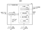
- FIG. 6 is a schematic diagram showing the configuration of the inter predicted image generation unit 309 included in the predicted image generation unit 308 according to this embodiment.
- the inter predicted image generation unit 309 includes a motion compensation unit (predicted image generation device) 3091 and a synthesizing unit 3095 .
- the synthesizing section 3095 includes an IntraInter synthesizing section 30951 , a GPM synthesizing section 30952 , a BIO section 30954 and a weight predicting section 3094 .
- the motion compensation unit 3091 (interpolated image generation unit 3091) performs interpolation by reading reference blocks from the reference picture memory 306 based on the inter prediction parameters (predFlagLX, refIdxLX, mvLX) input from the inter prediction parameter derivation unit 303. Generate an image (motion compensated image).
- the reference block is a block on the reference picture RefPicLX specified by refIdxLX, which is shifted by mvLX from the position of the target block.
- refIdxLX a filter that is shifted by mvLX from the position of the target block.
- an interpolated image is generated by applying a filter called a motion compensation filter for generating pixels at decimal positions.
- the motion compensation unit 3091 first derives the integer position (xInt, yInt) and phase (xFrac, yFrac) corresponding to the intra-prediction block coordinates (x, y) using the following equations.
- the motion compensation unit 3091 derives a temporary image temp[][] by performing horizontal interpolation processing on the reference picture refImg using an interpolation filter.
- shift1 is a normalization parameter that adjusts the range of values
- offset1 1 ⁇ (shift1-1).
- temp[x][y] ( ⁇ mcFilter[xFrac][k]*refImg[xInt+k-NTAP/2+1][yInt]+offset1)>>shift1
- the motion compensation unit 3091 derives an interpolated image Pred[][] by subjecting the temporary image temp[][] to vertical interpolation processing.
- shift2 is a normalization parameter that adjusts the range of values
- offset2 1 ⁇ (shift2-1).
- Pred[x][y] ( ⁇ mcFilter[yFrac][k]*temp[x][y+k-NTAP/2+1]+offset2)>>shift2
- the above Pred[][] is derived for each L0 list and L1 list (referred to as interpolated images PredL0[][] and PredL1[][]), and PredL0[][] and PredL1[ ][] to generate an interpolated image Pred[][].
- IntraInter synthesizing unit 30951 When ciip_mode is 1, the IntraInter synthesizing unit 30951 generates a CIIP (Combined intra inter prediction) mode prediction image by weighting the sum of the inter prediction image and the intra prediction image.
- CIIP Combined intra inter prediction
- the prediction value in CIIP mode is calculated by the weighted average of the inter-predicted image derived in merge mode and the intra-predicted image derived in planar prediction. Combining weights are determined by the prediction modes of adjacent coded blocks. If intra-prediction is used in both of the two adjacent blocks (upward and leftward) of the current block, the inter-prediction and intra-prediction combining ratio is 1:3. On the other hand, if neither of the two adjacent blocks are intra prediction, the synthesis ratio of inter prediction and intra prediction is set to 3:1. Otherwise, the ratio is 2:2. The same weighting factor is applied to both luminance and chrominance.
- BIO unit 30954 refers to two predicted images (first predicted image and second predicted image) and a gradient correction term to generate a predicted image in the bi-prediction mode.
- the weight prediction unit 3094 generates a block prediction image by multiplying the interpolation image PredLX by a weighting factor.
- PredFlagL0 or predFlagL1 is 1 (uni-prediction) and weight prediction is not used, the following equation processing is performed to adjust PredLX (LX is L0 or L1) to the pixel bit number bitDepth.
- the weight prediction unit 3094 derives the weight prediction coefficient w0 and the offset o0 from the encoded data, and performs the processing of the following formula.
- Pred[x][y] Clip3(0,(1 ⁇ bitDepth)-1,((PredLX[x][y]*w0+2 ⁇ (log2WD-1))>>log2WD)+o0)
- log2WD is a variable indicating a predetermined shift amount.
- the weight prediction unit 3094 derives weight prediction coefficients w0, w1, o0, and o1 from the encoded data, and performs the processing of the following equations.
- Pred[x][y] Clip3(0,(1 ⁇ bitDepth)-1,(PredL0[x][y]*w0+PredL1[x][y]*w1+((o0+o1+1) ⁇ log2WD))>>(log2WD+1))
- the inter predicted image generating unit 309 outputs the generated block predicted image to the adding unit 312 .
- the intra prediction image generation unit performs intra prediction using the intra prediction parameters input from the intra prediction parameter derivation unit and the reference pixels read from the reference picture memory 306 .
- the inverse quantization/inverse transform unit 311 inversely quantizes the quantized transform coefficients input from the parameter decoding unit 302 to obtain transform coefficients.
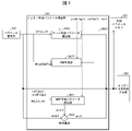
- FIG. 20 is a block diagram showing the configuration of the inverse quantization/inverse transform unit 311 of this embodiment.
- the inverse quantization/inverse transform unit 311 is composed of a scaling unit 31111 , an inverse non-separable transform unit 31121 and an inverse core transform unit 31123 .
- the inverse quantization/inverse transform unit 311 scales (inverse quantizes) the quantized transform coefficients qd[][] input from the entropy decoding unit 301 by the scaling unit 31111 to obtain transform coefficients d[][].
- This quantized transform coefficient qd[][] is quantized by transforming the prediction error, such as DCT (Discrete Cosine Transform) or DST (Discrete Sine Transform), in the encoding process. or the coefficients obtained by further non-separating transformation of the transformed coefficients.
- inverse frequency transform such as inverse DCT and inverse DST is performed on the transform coefficients to calculate prediction errors.
- Inverse quantization/inverse transform section 311 outputs the prediction error to addition section 312 .
- transformation and inverse transformation may be interpreted by replacing each other.
- the transform may be called a forward transform.
- the non-separable transform the non-separable transform
- the forward non-separable transform the non-separable transform
- core transformations are simply referred to as transformations.
- d[x][y] is transmitted to the inverse core transform unit 31123 or the inverse non-separable transform unit 31121.
- the inverse non-separable transform unit 31121 applies an inverse non-separable transform to the transform coefficients d[][] after the inverse quantization and before the core transform.
- the inverse non-separable transform is applied to the transform coefficients of part or all of the TU in the video decoding device 31 .
- an inverse separable transform (such as DCT2 and DST7) is applied to the transform coefficients after the inverse non-separable transform.
- the non-separable transform and the inverse non-separable transform are applied only to a predetermined upper left sub-block.
- TU sizes where one of TU width W and height H is 4 are, for example, 4 ⁇ 4, 8 ⁇ 4, 4 ⁇ 8, L ⁇ 4, and 4 ⁇ L (L is a natural number of 16 or more). is mentioned.
- RST Reduced Secondary Transform
- LFNST Low Frequency Non-Separable-Transform
- the number nonZeroSize of the transform coefficients of the non-separable transform to be transmitted is equal to or smaller than the size of the separable transform ((1 ⁇ log2StSize)x(1 ⁇ log2StSize))
- LFNST the error-adapted transform for GPM prediction
- GPM non-separable transform or GPM_LFNST.
- FIG. 22 shows an example of CU reporting lfnst_idx and mtx_idx
- FIG. 23 shows an example of TU reporting lfnst_idx and mtx_idx.
- the TU decoding unit 3024 decodes the index mts_idx indicating the transform matrix of the separation transform from the encoded data.
- the TU decoding unit 3024 decodes the index lfnst_idx from the encoded data.
- lfnst_idx is an index indicating whether non-separable transform is used and a transform matrix.
- the TU decoder 3024 derives the flag LfnstDcOnly and the flag LfnstZeroOutSigCoeffFlag.
- LfnstDcOnly is a flag indicating whether transform coefficients are DC only
- LfnstZeroOutSigCoeffFlag is a flag indicating whether transform coefficients exist in a predetermined high frequency region (zero-out region).
- the width and height of the CU may be limited to 4 or more, or MIP prediction in small blocks may be excluded (block size limited to a predetermined size or more).
- the TU decoding unit 3024 decodes lfnst_idx when the prediction mode is intra prediction mode and sps_lfnst_enabled_flag is 1 (SYN_LFNST_INTRA), or when the prediction mode is inter and sps_gpm_lfnst_enabled_flag is 1 (SYN_GPM_INTRA). If lfnst_idx is 0, it indicates that no non-separable transformation is applied, if it is 1, it indicates that one of the non-separable transformation matrix sets (pairs) is used, and if it is 2, the other of the pair indicates that the conversion of
- lfnst_idx may be restricted to ⁇ 0,1 ⁇ or ⁇ 0,2 ⁇ , which reduces the cost of flags needed when applying GPM non-separate transforms to inter-CUs.
- the TU decoding unit 3024 decodes the syntax element indicating whether or not to use the non-separable transform
- the TU decoding unit 3024 may decode lfnst_flag first, and then decode lfnst_set_flag when the prediction mode is intra prediction.
- TR code Truncated Rice code
- the inverse non-separable transform unit 31121 derives a transform matrix secTransMatrix[][] used in transform processing.
- the inverse non-separable transform unit 31121 derives lfnstTrSetId from the intra prediction mode IntraPredMode.
- lfnstTrSetId is derived from the block size or the GPM angle index angleIdx (or the GPM mode number merge_gpm_partition_idx).
- lfnstTrSetId is a number indicating a set of transformation matrices for non-separable transformation.
- the non-separable transform can use multiple predetermined transform matrices, and by selecting an appropriate transform matrix from the intra-prediction mode or GPM mode, suitable transform is possible.
- FIG. 14 is a table used for non-separable transform matrices in intra prediction mode.
- the inverse non-separable transform unit 31121 derives a non-separable transform matrix, here a transform matrix set number (lfnstTrSetId), from the intra prediction mode IntraPredMode using the table in FIG. If the table is an array of nstSetTableIntra, the following lookup table may be used to derive lfnstTrSetId.
- lfnstTrSetId transform matrix set number
- the following example describes the processing for a lookup table.
- Fig. 15 is a table used for deriving a transformation matrix for non-separable transformation in GPM mode.
- the inverse non-separable transform unit 31121 derives a non-separable transform set number (lfnstTrSetIdx) from the angle index angleIdx using the table nstSetTableGPMangle1.
- A, B, A, B, A, B, A, B (matrix are allocated as M2, M3, M2, M1, M2, M3, M2, M1). 11.25 degrees is an angle obtained by dividing 360 degrees into 32.
- the B extents are another transformation matrix for each extent offset by 90 degrees.
- M3 and M1 are used.
- the same transformation matrix is used for the 180 degree offset range (180 degree offset angle). In other words, if the absolute difference of angleIdx is a difference of 180 degrees (16 here), the same value is used for lfnstTrSetIdx.
- the transformation matrix is the same when shifted by 90 degrees (angleIdx difference is 8).
- lfnstTrSetId is assigned in units of two values of angleIdx, ie, two angles of 11.25 degrees combined to form a range of 22.5 degrees.
- the transformation matrix is the same when shifted by 90 degrees.
- nstSetTableGPMangle3[] ⁇ 0, 0, 1, 1, 2, 2, 3, 3, 0, 0, 1, 1, 2, 2, 3, 3. 0, 0, 1, 1, 2, 2, 3, 3 ⁇
- the following tables with shifted positions may be used.
- nstSetTableGPMangle3[] ⁇ 0, 1, 1, 2, 2, 3, 3, 0, 0, 1, 1, 2, 2, 3, 3. 0, 0, 1, 1, 2, 2, 3, 3 , 0, 0, 1, 1, 2, 2, 3, 3, 0 ⁇
- the transformation matrix is the same when shifted by 90 degrees (angleIdx difference is 8).
- the transformation matrix is the same for a 180 degree shift (angleIdx difference is 16).
- lfnstTrSetId may be assigned in units of two values of angleIdx, that is, a range of 22.5 degrees obtained by combining two angles of 11.25 degrees.
- nstSetTableGPMangle5[] ⁇ 0, 0, 1, 1, 2, 2, 3, 3, 4, 4, 5, 6, 6, 7, 7. 0, 0, 1, 1, 2, 2, 3 , 3, 4, 4, 5, 6, 6, 7, 7 ⁇
- the following tables with shifted positions may be used.
- nstSetTableGPMangle5[] ⁇ 0, 1, 1, 2, 2, 3, 3, 4, 4, 5, 5, 6, 6, 7, 7. 0, 0, 1, 1, 2, 2, 3, 3 , 4, 4, 5, 5, 6, 6, 7, 7, 0 ⁇
- the transformation matrix is the same for a 180 degree shift (angleIdx difference is 16).
- FIG. 18 is a table used for deriving a transformation matrix for non-separable transformation in GPM mode.
- the inverse non-separable transform unit 31121 derives a non-separable transform set number (lfnstTrSetId) from the GPM partition information merge_gpm_partition_idx using the table nstSetTableGPMangleS.
- lfnstTrSetId non-separable transform set number
- 0 to 3 are used as lfnstTrSetId for intra prediction
- 4 to 6 are used as lfnstTrSetId for inter prediction (here, GPM).
- nstSetTableGPMangleS[] ⁇ 5, 5, 6, 6, 6, 6, 6, 5, 5, 5, 4, 4, 4, 4, 5, 5, 6,6, 6, 6, 6, 6 , 5, 5, 5, 4, 4, 4, 4, 5, 5 ⁇
- Fig. 19 is a table used to derive a transformation matrix for non-separable transformation in GPM mode.
- the inverse non-separable transform unit 31121 derives a non-separable transform set number (lfnstTrSetId) from the GPM partition information merge_gpm_partition_idx using the table nstSetTableGPMpart.
- lfnstTrSetId nstSetTableGPMpart[merge_gpm_partition_idx]
- the inverse non-separable transform unit 31121 derives the transform matrix secTranMatrix[][] from the non-separable transform set number (lfnstTrSetId), lfnst_idx indicating the non-separable transform matrix, and the non-separable transform size nStSize (nTrS).
- the predicted image generated from the GPM has the direction indicated by the angleIdx of the GPM, and the residual of the GPM may also have the same direction. According to the above configuration, when the GPM mode is used, the residual transform coefficients can be further concentrated in the low frequency region by non-separating transform using the directionality of the GPM division pattern. Therefore, there is an effect that the encoding efficiency is improved.
- nStOutSize represents the number of output transform coefficients
- nonZeroSize represents the number of applied transform coefficients (input transform coefficients)
- numStX, numStY represent the number of sub-blocks to which the inverse non-separable transform is applied.
- the inverse non-separable transform 48 transform coefficients are output by the inverse non-separable transform of RST8x8 if the TU is greater than or equal to a predetermined size. Otherwise, the inverse non-separable transform of RST4x4 outputs 16 transform coefficients. If the TU is 4x4, 16 transform coefficients are derived from 8 transform coefficients using RST4x4, and if the TU is 8x8, 48 transform coefficients are derived from 8 transform coefficients using RST8x8. Otherwise, output 16 transform coefficients to 16 or 48 transform coefficients depending on the size of the TU.
- nStOutSize 16
- the input nonZeroSize of LFNST is not limited to 8 and 16.
- 12 may be used.
- the output nStOutSize is also not limited to 16 and 48, and may be 32, 36, 64, or the like.
- xC and yC are positions on the TU, and are derived from the array DiagScanOrder indicating the scan order and the position x of the array u[].
- xC (xSbIdx ⁇ log2StSize) + DiagScanOrder[log2StSize][log2StSize][x][0]
- yC (ySbIdx ⁇ log2StSize) + DiagScanOrder[log2StSize][log2StSize][x][1]
- u[x] d[xC][yC] Note that the range copied to the one-dimensional array is called an area RU.
- the inverse non-separable transform unit 31121 transforms u[] of length nonZeroSize using the transform matrix secTransMatrix[][], and outputs a one-dimensional array of coefficients v'[] of length nStOutSize. to derive
- the inverse non-separable transformation unit 31121 performs a product-sum operation between the transformation matrix and the one-dimensional variable u[], as shown in the following equation.
- the inverse non-separable transform unit 31121 arranges the transformed one-dimensional array coefficient v'[] at a predetermined position in the TU again.
- the arrangement method may be changed according to predModeIntra.
- predModeIntra ⁇ 34
- the following processing may be applied.
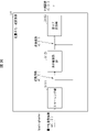
- FIG. 24 is a flow chart showing the flow of processing when non-separable conversion is performed by GPM.
- (S2200) Perform non-separable transformation using transformation matrix secTranMatrix[][]. Specifically, the processing from S2201 to S2204 described above may be performed.
- the addition unit 312 adds the predicted image of the block input from the predicted image generation unit 308 and the prediction error input from the inverse quantization/inverse transform unit 311 for each pixel to generate a decoded image of the block.
- the adder 312 stores the decoded image of the block in the reference picture memory 306 and also outputs it to the loop filter 305 .
- FIG. 7 is a block diagram showing the configuration of the video encoding device 11 according to this embodiment.
- the video encoding device 11 includes a predicted image generation unit 101, a subtraction unit 102, a transformation/quantization unit 103, an inverse quantization/inverse transformation unit 105, an addition unit 106, a loop filter 107, a prediction parameter memory (prediction parameter storage unit , frame memory) 108, reference picture memory (reference image storage unit, frame memory) 109, coding parameter determination unit 110, parameter coding unit 111, prediction parameter derivation unit 120, and entropy coding unit 104.
- a prediction parameter memory prediction parameter storage unit , frame memory
- reference picture memory reference image storage unit, frame memory
- the predicted image generation unit 101 generates a predicted image for each CU.
- the predicted image generation unit 101 includes the already described inter predicted image generation unit 309 and intra predicted image generation unit, and the description thereof is omitted.
- the subtraction unit 102 subtracts the pixel values of the predicted image of the block input from the predicted image generation unit 101 from the pixel values of the image T to generate prediction errors.
- Subtraction section 102 outputs the prediction error to transform/quantization section 103 .
- the transform/quantization unit 103 calculates transform coefficients by frequency transforming the prediction error input from the subtraction unit 102, and derives quantized transform coefficients by quantization.
- the transform/quantization unit 103 outputs the quantized transform coefficients to the parameter coding unit 111 and the inverse quantization/inverse transform unit 105 .
- the inverse quantization/inverse transform unit 105 is the same as the inverse quantization/inverse transform unit 311 in the moving image decoding device 31, and description thereof is omitted.
- the calculated prediction error is output to addition section 106 .
- the parameter encoding unit 111 includes a header encoding unit 1110, a CT information encoding unit 1111, and a CU encoding unit 1112 (prediction mode encoding unit).
- CU encoding section 1112 further comprises TU encoding section 1114 . The general operation of each module will be described below.
- a header encoding unit 1110 performs encoding processing of parameters such as header information, division information, prediction information, and quantized transform coefficients.
- a CT information encoding unit 1111 encodes QT, MT (BT, TT) division information and the like.
- a CU encoding unit 1112 encodes CU information, prediction information, division information, and the like.
- the TU encoding unit 1114 encodes the QP update information and the quantized prediction error when the TU contains the prediction error.
- the CT information encoding unit 1111 and the CU encoding unit 1112 parameter-encode syntax elements such as inter prediction parameters (predMode, merge_flag, merge_idx, inter_pred_idc, refIdxLX, mvp_LX_idx, mvdLX), intra prediction parameters, and quantized transform coefficients.
- inter prediction parameters predMode, merge_flag, merge_idx, inter_pred_idc, refIdxLX, mvp_LX_idx, mvdLX
- intra prediction parameters e.g., intra prediction parameters supplied to section 111.
- the entropy coding unit 104 receives input from the parameter coding unit 111 of the quantized transform coefficients and coding parameters (division information, prediction parameters). The entropy encoding unit 104 entropy-encodes these to generate and output an encoded stream Te.
- the prediction parameter derivation unit 120 is means including the inter prediction parameter encoding unit 112 and the intra prediction parameter encoding unit, and derives intra prediction parameters and intra prediction parameters from the parameters input from the encoding parameter determination unit 110.
- the derived intra prediction parameters and intra prediction parameters are output to parameter coding section 111 .
- Inter prediction parameter encoding section 112 is configured including parameter encoding control section 1121 and inter prediction parameter derivation section 303, as shown in FIG.
- the inter-prediction parameter deriving unit 303 has a configuration common to that of the video decoding device.
- Parameter encoding control section 1121 includes merge index derivation section 11211 and vector candidate index derivation section 11212 .
- the merge index derivation unit 11211 derives merge candidates and the like, and outputs them to the inter prediction parameter derivation unit 303.
- Vector candidate index derivation section 11212 derives vector prediction candidates and the like, and outputs them to inter prediction parameter derivation section 303 and parameter coding section 111 .
- the intra prediction parameter encoding unit includes a parameter encoding control unit and an intra prediction parameter derivation unit.
- the intra-prediction parameter deriving unit has a configuration common to that of the video decoding device.
- the inputs to the inter-prediction parameter derivation unit 303 and the intra-prediction parameter derivation unit are the coding parameter determination unit 110 and the prediction parameter memory 108, and are output to the parameter coding unit 111.
- the addition unit 106 adds pixel values of the prediction block input from the prediction image generation unit 101 and prediction errors input from the inverse quantization/inverse transformation unit 105 for each pixel to generate a decoded image.
- the addition unit 106 stores the generated decoded image in the reference picture memory 109 .
- a loop filter 107 applies a deblocking filter, SAO, and ALF to the decoded image generated by the addition unit 106.
- the prediction parameter memory 108 stores the prediction parameters generated by the coding parameter determination unit 110 in predetermined positions for each current picture and CU.
- the reference picture memory 109 stores the decoded image generated by the loop filter 107 in a predetermined position for each target picture and CU.
- the coding parameter determination unit 110 selects one set from a plurality of sets of coding parameters.
- the coding parameter is the above-described QT, BT or TT division information, prediction parameters, or parameters to be coded generated in relation to these.
- the predicted image generating unit 101 generates predicted images using these coding parameters.
- the coding parameter determination unit 110 calculates an RD cost value indicating the magnitude of the information amount and the coding error for each of the multiple sets.
- the RD cost value is, for example, the sum of the code amount and the value obtained by multiplying the squared error by the coefficient ⁇ .
- the code amount is the information amount of the encoded stream Te obtained by entropy-encoding the quantization error and encoding parameters.
- the squared error is the sum of squares of the prediction errors calculated in subtraction section 102 .
- the coefficient ⁇ is a preset real number greater than zero. Coding parameter determination section 110 selects a set of coding parameters that minimizes the calculated cost value. Coding parameter determination section 110 outputs the determined coding parameters to parameter coding section 111 and prediction parameter derivation section 120 .
- a program for realizing this control function may be recorded in a computer-readable recording medium, and the program recorded in this recording medium may be read into a computer system and executed.
- the “computer system” here is a computer system built into either the moving image encoding device 11 or the moving image decoding device 31, and includes hardware such as an OS and peripheral devices.
- the term "computer-readable recording medium” refers to portable media such as flexible discs, magneto-optical discs, ROMs, and CD-ROMs, and storage devices such as hard disks built into computer systems.
- “computer-readable recording medium” means a medium that dynamically stores a program for a short period of time, such as a communication line for transmitting a program via a network such as the Internet or a communication line such as a telephone line. In that case, it may also include a memory that holds the program for a certain period of time, such as a volatile memory inside a computer system that serves as a server or client. Further, the program may be for realizing part of the functions described above, or may be capable of realizing the functions described above in combination with a program already recorded in the computer system.
- part or all of the video encoding device 11 and the video decoding device 31 in the above-described embodiments may be implemented as an integrated circuit such as LSI (Large Scale Integration).
- LSI Large Scale Integration
- Each functional block of the moving image encoding device 11 and the moving image decoding device 31 may be processorized individually, or may be partially or wholly integrated and processorized.
- the method of circuit integration is not limited to LSI, but may be realized by a dedicated circuit or a general-purpose processor.
- an integrated circuit based on this technology may be used.
- Embodiments of the present invention are preferably applied to a moving image decoding device that decodes encoded image data and a moving image encoding device that generates encoded image data. be able to. Also, the present invention can be preferably applied to the data structure of encoded data generated by a video encoding device and referenced by a video decoding device.
- Image decoder 301 Entropy Decoder 302 Parameter decoder 303 Inter prediction parameter derivation unit 30377 GPM predictor 305, 107 loop filter 306, 109 Reference picture memory 307, 108 prediction parameter memory 308, 101 Predictive image generator 309 Inter prediction image generator 30952 GPM Synthesizer 311, 105 Inverse quantization/inverse transform section 312, 106 adder 11 Image encoding device 102 Subtractor 103 Transform/Quantization Unit 104 Entropy Encoder 110 Encoding parameter determination unit 111 Parameter encoder 112 Inter prediction parameter coding unit 120 Prediction parameter derivation unit
Abstract
符号化効率を向上させることができる動画像符号化・復号装置(11、31)を提供する。本発明の一態様に係る動画像復号装置(31)は、角度変数により導出される重みパラメータを用いて予測画像を導出する予測部(30377)と、非分離変換を行う非分離変換部(31121)を備えている動画像復号装置(31)であって、上記非分離変換部(31121)は、インター予測モードがGPMモードである場合、GPMの分割情報(merge_gpm_partition_idx)から非分離変換のセット番号(lfnstTrSetId)を導出することを特徴とする。
Description
本発明の実施形態は、動画像復号装置および動画像符号化装置に関する。
動画像を効率的に伝送または記録するために、動画像を符号化することによって符号化データを生成する動画像符号化装置、および、当該符号化データを復号することによって復号画像を生成する動画像復号装置が用いられている。
具体的な動画像符号化方式としては、例えば、H.264/AVCやHEVC(High-Efficiency Video Coding)方式などが挙げられる。
このような動画像符号化方式においては、動画像を構成する画像(ピクチャ)は、画像を分割することにより得られるスライス、スライスを分割することにより得られる符号化ツリーユニット(CTU:Coding Tree Unit)、符号化ツリーユニットを分割することで得られる符号化単位(符号化ユニット(Coding Unit:CU)と呼ばれることもある)、及び、符号化単位を分割することより得られる変換ユニット(TU:Transform Unit)からなる階層構造により管理され、CU毎に符号化/復号される。
また、このような動画像符号化方式においては、通常、入力画像を符号化/復号することによって得られる局所復号画像に基づいて予測画像が生成され、当該予測画像を入力画像(原画像)から減算して得られる予測誤差(「差分画像」または「残差画像」と呼ぶこともある)が符号化される。予測画像の生成方法としては、画面間予測(インター予測)、および、画面内予測(イントラ予測)が挙げられる。
また、非特許文献1には、対象ブロックを矩形以外の形状に分割し、領域ごとに異なるインター予測を実施するGPM(Geometric partition mode)モードが開示されている。このように対象ブロックを矩形以外の形状に分割することにより、複雑なテクスチャに対してもより正確に予測することができ、符号化効率が向上する。また、非特許文献1には、変換ユニット毎に、予測誤差を分離変換した係数をさらに低周波数領域に集中させるために、非分離変換する画像符号化装置が開示されている。
ITU-T Rec. H.266
非特許文献1では、方向性をもつ予測残差に対し有効な非分離変換及び逆非分離変換技術が、イントラ予測ブロックのみに適用され、斜め方向が多く存在するインター予測ブロックには適応されていない。
本発明は、より好適に逆非分離変換を適用することができる動画像復号装置、動画像符号化装置及びその関連技術を提供することを目的とする。
上記の課題を解決するために、本発明の一態様に係る動画像復号装置は、角度変数により導出される重みパラメータを用いて予測画像を導出する予測部と、非分離変換を行う非分離変換部を備えている動画像復号装置であって、上記分離変換部は、インター予測モードがGPMモードである場合、GPMの分割情報(merge_gpm_partition_idx)から非分離変換のセット番号(lfnstTrSetId)を導出することを特徴とする。
本発明の別の一態様に係る動画像符号化装置は、角度変数により導出される重みパラメータを用いて予測画像を導出する予測部と、非分離変換を行う非分離変換部を備えている動画像符号化装置であって、上記分離変換部は、インター予測モードがGPMモードである場合、GPMの分割情報(merge_gpm_partition_idx)から非分離変換のセット番号(lfnstTrSetId)を導出することを特徴とする。
本発明の態様によれば、動画像符号化・復号処理において、符号化効率を向上させることができる。
(第1の実施形態)
以下、図面を参照しながら本発明の実施形態について説明する。
以下、図面を参照しながら本発明の実施形態について説明する。
図1は、本実施形態に係る画像伝送システム1の構成を示す概略図である。
画像伝送システム1は、対象画像を符号化した符号化ストリームを伝送し、伝送された符号化ストリームを復号し画像を表示するシステムである。画像伝送システム1は、動画像符号化装置(画像符号化装置)11、ネットワーク21、動画像復号装置(画像復号装置)31、及び動画像表示装置(画像表示装置)41を含んで構成される。
動画像符号化装置11には画像Tが入力される。
ネットワーク21は、動画像符号化装置11が生成した符号化ストリームTeを動画像復号装置31に伝送する。ネットワーク21は、インターネット(Internet)、広域ネットワーク(WAN:Wide Area Network)、小規模ネットワーク(LAN:Local Area Network)またはこれらの組み合わせである。ネットワーク21は、必ずしも双方向の通信網に限らず、地上デジタル放送、衛星放送等の放送波を伝送する一方向の通信網であっても良い。また、ネットワーク21は、DVD(Digital Versatile Disc:登録商標)、BD(Blue-ray Disc:登録商標)等の符号化ストリームTeを記録した記憶媒体で代替されても良い。
動画像復号装置31は、ネットワーク21が伝送した符号化ストリームTeのそれぞれを復号し、復号した1または複数の復号画像Tdを生成する。
動画像表示装置41は、動画像復号装置31が生成した1または複数の復号画像Tdの全部または一部を表示する。動画像表示装置41は、例えば、液晶ディスプレイ、有機EL(Electro-luminescence)ディスプレイ等の表示デバイスを備える。ディスプレイの形態としては、据え置き、モバイル、HMD等が挙げられる。また、動画像復号装置31が高い処理能力を有する場合には、画質の高い画像を表示し、より低い処理能力しか有しない場合には、高い処理能力、表示能力を必要としない画像を表示する。
<演算子>
本明細書で用いる演算子を以下に記載する。
本明細書で用いる演算子を以下に記載する。
>>は右ビットシフト、<<は左ビットシフト、&はビットワイズAND、|はビットワイズOR、|=はOR代入演算子であり、||は論理和を示す。
x?y:zは、xが真(0以外)の場合にy、xが偽(0)の場合にzをとる3項演算子である。
Clip3(a,b,c)は、cをa以上b以下の値にクリップする関数であり、c<aの場合にはaを返し、c>bの場合にはbを返し、その他の場合にはcを返す関数である(ただし、a<=b)。
abs(a)はaの絶対値を返す関数である。
Int(a)はaの整数値を返す関数である。
floor(a)はa以下の最大の整数を返す関数である。
ceil(a)はa以上の最小の整数を返す関数である。
a/dはdによるaの除算(小数点以下切り捨て)を表す。
<符号化ストリームTeの構造>
本実施形態に係る動画像符号化装置11および動画像復号装置31の詳細な説明に先立って、動画像符号化装置11によって生成され、動画像復号装置31によって復号される符号化ストリームTeのデータ構造について説明する。
本実施形態に係る動画像符号化装置11および動画像復号装置31の詳細な説明に先立って、動画像符号化装置11によって生成され、動画像復号装置31によって復号される符号化ストリームTeのデータ構造について説明する。
図2は、符号化ストリームTeにおけるデータの階層構造を示す図である。符号化ストリームTeは、例示的に、シーケンス、およびシーケンスを構成する複数のピクチャを含む。図2の(a)~(f)は、それぞれ、シーケンスSEQを既定する符号化ビデオシーケンス、ピクチャPICTを規定する符号化ピクチャ、スライスSを規定する符号化スライス、スライスデータを規定する符号化スライスデータ、符号化スライスデータに含まれる符号化ツリーユニット、符号化ツリーユニットに含まれる符号化ユニットを示す図である。
(符号化ビデオシーケンス)
符号化ビデオシーケンスでは、処理対象のシーケンスSEQを復号するために動画像復号装置31が参照するデータの集合が規定されている。シーケンスSEQは、図2に示すように、ビデオパラメータセット(Video Parameter Set)、シーケンスパラメータセットSPS(Sequence Parameter Set)、ピクチャパラメータセットPPS(Picture Parameter Set)、Adaptation Parameter Set(APS)、ピクチャPICT、及び、付加拡張情報SEI(Supplemental Enhancement Information)を含んでいる。
符号化ビデオシーケンスでは、処理対象のシーケンスSEQを復号するために動画像復号装置31が参照するデータの集合が規定されている。シーケンスSEQは、図2に示すように、ビデオパラメータセット(Video Parameter Set)、シーケンスパラメータセットSPS(Sequence Parameter Set)、ピクチャパラメータセットPPS(Picture Parameter Set)、Adaptation Parameter Set(APS)、ピクチャPICT、及び、付加拡張情報SEI(Supplemental Enhancement Information)を含んでいる。
ビデオパラメータセットVPSは、複数のレイヤから構成されている動画像において、複数の動画像に共通する符号化パラメータの集合および動画像に含まれる複数のレイヤおよび個々のレイヤに関連する符号化パラメータの集合が規定されている。
シーケンスパラメータセットSPSでは、対象シーケンスを復号するために動画像復号装置31が参照する符号化パラメータの集合が規定されている。例えば、ピクチャの幅や高さが規定される。なお、SPSは複数存在してもよい。その場合、PPSから複数のSPSの何れかを選択する。
ピクチャパラメータセットPPSでは、対象シーケンス内の各ピクチャを復号するために動画像復号装置31が参照する符号化パラメータの集合が規定されている。例えば、ピクチャの復号に用いられる量子化幅の基準値(pic_init_qp_minus26)や重み付き予測の適用を示すフラグ(weighted_pred_flag)が含まれる。なお、PPSは複数存在してもよい。その場合、対象シーケンス内の各ピクチャから複数のPPSの何れかを選択する。
(符号化ピクチャ)
符号化ピクチャでは、処理対象のピクチャPICTを復号するために動画像復号装置31が参照するデータの集合が規定されている。ピクチャPICTは、図2に示すように、スライス0~スライスNS-1を含む(NSはピクチャPICTに含まれるスライスの総数)。
符号化ピクチャでは、処理対象のピクチャPICTを復号するために動画像復号装置31が参照するデータの集合が規定されている。ピクチャPICTは、図2に示すように、スライス0~スライスNS-1を含む(NSはピクチャPICTに含まれるスライスの総数)。
なお、以下、スライス0~スライスNS-1のそれぞれを区別する必要が無い場合、符号の添え字を省略して記述することがある。また、以下に説明する符号化ストリームTeに含まれるデータであって、添え字を付している他のデータについても同様である。
(符号化スライス)
符号化スライスでは、処理対象のスライスSを復号するために動画像復号装置31が参照するデータの集合が規定されている。スライスは、図2に示すように、スライスヘッダ、および、スライスデータを含んでいる。
符号化スライスでは、処理対象のスライスSを復号するために動画像復号装置31が参照するデータの集合が規定されている。スライスは、図2に示すように、スライスヘッダ、および、スライスデータを含んでいる。
スライスヘッダには、対象スライスの復号方法を決定するために動画像復号装置31が参照する符号化パラメータ群が含まれる。スライスタイプを指定するスライスタイプ指定情報(slice_type)は、スライスヘッダに含まれる符号化パラメータの一例である。
スライスタイプ指定情報により指定可能なスライスタイプとしては、(1)符号化の際にイントラ予測のみを用いるIスライス、(2)符号化の際に単方向予測、または、イントラ予測を用いるPスライス、(3)符号化の際に単方向予測、双方向予測、または、イントラ予測を用いるBスライスなどが挙げられる。なお、インター予測は、単予測、双予測に限定されず、より多くの参照ピクチャを用いて予測画像を生成してもよい。以下、P、Bスライスと呼ぶ場合には、インター予測を用いることができるブロックを含むスライスを指す。
なお、スライスヘッダは、ピクチャパラメータセットPPSへの参照(pic_parameter_set_id)を含んでいても良い。
(符号化スライスデータ)
符号化スライスデータでは、処理対象のスライスデータを復号するために動画像復号装置31が参照するデータの集合が規定されている。スライスデータは、図2(d)に示すように、CTUを含んでいる。CTUは、スライスを構成する固定サイズ(例えば64x64)のブロックであり、最大符号化単位(LCU:Largest Coding Unit)と呼ぶこともある。
符号化スライスデータでは、処理対象のスライスデータを復号するために動画像復号装置31が参照するデータの集合が規定されている。スライスデータは、図2(d)に示すように、CTUを含んでいる。CTUは、スライスを構成する固定サイズ(例えば64x64)のブロックであり、最大符号化単位(LCU:Largest Coding Unit)と呼ぶこともある。
(符号化ツリーユニット)
図2には、処理対象のCTUを復号するために動画像復号装置31が参照するデータの集合が規定されている。CTUは、再帰的な4分木分割(QT(Quad Tree)分割)、2分木分割(BT(Binary Tree)分割)あるいは3分木分割(TT(Ternary Tree)分割)により、符号化処理の基本的な単位である符号化ユニットCUに分割される。BT分割とTT分割を合わせてマルチツリー分割(MT(Multi Tree)分割)と呼ぶ。再帰的な4分木分割により得られる木構造のノードのことを符号化ノード(Coding Node)と称する。4分木、2分木、及び3分木の中間ノードは、符号化ノードであり、CTU自身も最上位の符号化ノードとして規定される。
図2には、処理対象のCTUを復号するために動画像復号装置31が参照するデータの集合が規定されている。CTUは、再帰的な4分木分割(QT(Quad Tree)分割)、2分木分割(BT(Binary Tree)分割)あるいは3分木分割(TT(Ternary Tree)分割)により、符号化処理の基本的な単位である符号化ユニットCUに分割される。BT分割とTT分割を合わせてマルチツリー分割(MT(Multi Tree)分割)と呼ぶ。再帰的な4分木分割により得られる木構造のノードのことを符号化ノード(Coding Node)と称する。4分木、2分木、及び3分木の中間ノードは、符号化ノードであり、CTU自身も最上位の符号化ノードとして規定される。
CTは、CT情報として、CT分割を行うか否かを示すCU分割フラグ(split_cu_flag)、QT分割を行うか否かを示すQT分割フラグ(qt_split_cu_flag)、MT分割の分割方向を示すMT分割方向(mtt_split_cu_vertical_flag)、MT分割の分割タイプを示すMT分割タイプ(mtt_split_cu_binary_flag)を含む。split_cu_flag、qt_split_cu_flag、mtt_split_cu_vertical_flag、mtt_split_cu_binary_flagは符号化ノード毎に伝送される。
輝度と色差で異なるツリーを用いても良い。ツリーの種別をtreeTypeで示す。例えば、輝度(Y, cIdx=0)と色差(Cb/Cr, cIdx=1,2)で共通のツリーを用いる場合、共通単一ツリーをtreeType=SINGLE_TREEで示す。輝度と色差で異なる2つのツリー(DUALツリー)を用いる場合、輝度のツリーをtreeType= DUAL_TREE_LUMA、色差のツリーをtreeType=DUAL_TREE_CHROMAで示す。
(符号化ユニット)
図2は、処理対象の符号化ユニットを復号するために動画像復号装置31が参照するデータの集合が規定されている。具体的には、CUは、CUヘッダCUH、予測パラメータ、変換パラメータ、量子化変換係数等から構成される。CUヘッダでは予測モード等が規定される。
図2は、処理対象の符号化ユニットを復号するために動画像復号装置31が参照するデータの集合が規定されている。具体的には、CUは、CUヘッダCUH、予測パラメータ、変換パラメータ、量子化変換係数等から構成される。CUヘッダでは予測モード等が規定される。
予測処理は、CU単位で行われる場合と、CUをさらに分割したサブCU単位で行われる場合がある。CUとサブCUのサイズが等しい場合には、CU中のサブCUは1つである。CUがサブCUのサイズよりも大きい場合、CUはサブCUに分割される。たとえばCUが8x8、サブCUが4x4の場合、CUは水平2分割、垂直2分割からなる、4つのサブCUに分割される。
予測の種類(予測モード)は、イントラ予測(MODE_INTRA)と、インター予測(MODE_INTER)、イントラブロックコピー(MODE_IBC)がある。イントラ予測は、同一ピクチャ内の予測であり、インター予測は、互いに異なるピクチャ間(例えば、表示時刻間、レイヤ画像間)で行われる予測処理を指す。
変換・量子化処理はCU単位で行われるが、量子化変換係数は4x4等のサブブロック単位でエントロピー符号化してもよい。
(予測パラメータ)
予測画像は、ブロックに付随する予測パラメータによって導出される。予測パラメータには、イントラ予測とインター予測の予測パラメータがある。
予測画像は、ブロックに付随する予測パラメータによって導出される。予測パラメータには、イントラ予測とインター予測の予測パラメータがある。
(イントラ予測の予測パラメータ)
イントラ予測の予測パラメータについて説明する。イントラ予測パラメータは、輝度予測モードIntraPredModeY(predModeIntra)、色差予測モードIntraPredModeCから構成される。イントラ予測モードは、例えば67種類(0~66)存在する。例えば、プレーナ予測(0)、DC予測(1)、Angular予測(2~66)である。
イントラ予測の予測パラメータについて説明する。イントラ予測パラメータは、輝度予測モードIntraPredModeY(predModeIntra)、色差予測モードIntraPredModeCから構成される。イントラ予測モードは、例えば67種類(0~66)存在する。例えば、プレーナ予測(0)、DC予測(1)、Angular予測(2~66)である。
(インター予測の予測パラメータ)
インター予測の予測パラメータについて説明する。インター予測パラメータは、予測リスト利用フラグpredFlagL0とpredFlagL1、参照ピクチャインデックスrefIdxL0とrefIdxL1、動きベクトルmvL0とmvL1から構成される。predFlagL0、predFlagL1は、参照ピクチャリスト(L0リスト、L1リスト)が用いられるか否かを示すフラグであり、値が1の場合に対応する参照ピクチャリストが用いられる。なお、本明細書中「XXであるか否かを示すフラグ」と記す場合、フラグが0以外(たとえば1)をXXである場合、0をXXではない場合とし、論理否定、論理積などでは1を真、0を偽と扱う(以下同様)。但し、実際の装置や方法では真値、偽値として他の値を用いることもできる。
インター予測の予測パラメータについて説明する。インター予測パラメータは、予測リスト利用フラグpredFlagL0とpredFlagL1、参照ピクチャインデックスrefIdxL0とrefIdxL1、動きベクトルmvL0とmvL1から構成される。predFlagL0、predFlagL1は、参照ピクチャリスト(L0リスト、L1リスト)が用いられるか否かを示すフラグであり、値が1の場合に対応する参照ピクチャリストが用いられる。なお、本明細書中「XXであるか否かを示すフラグ」と記す場合、フラグが0以外(たとえば1)をXXである場合、0をXXではない場合とし、論理否定、論理積などでは1を真、0を偽と扱う(以下同様)。但し、実際の装置や方法では真値、偽値として他の値を用いることもできる。
インター予測パラメータを導出するためのシンタックス要素には、例えば、マージフラグmerge_flag (general_merge_flag)、マージインデックスmerge_idx、アフィンモードなどのサブブロック単位のインター予測を用いるかを示すmerge_subblock_flag、regulare_merge_flag、イントラインターフラグciip_flag、GPMモード(Geometric partitioning merge mode)を用いるかを示すGPM_flag、GPMモードの分割形状を示すmerge_gpm_partition_idx、GPMのマージインデックスを示すmerge_gpm_idx0、merge_gpm_idx1、AMVPモードで用いる参照ピクチャを選択するためのインター予測識別子inter_pred_idc、参照ピクチャインデックスrefIdxLX、動きベクトルを導出するための予測ベクトルインデックスmvp_LX_idx、差分ベクトルmvdLX、動きベクトル精度モードamvr_modeがある。なお、GPM_flag(MergeGpmFlag)は明示的に符号化せず、ciip_flag=0の場合に、GPM_flag=1(MergeGpmFlag=1)と導出してもよい。
(参照ピクチャリスト)
参照ピクチャリストは、参照ピクチャメモリ306に記憶された参照ピクチャからなるリストである。
参照ピクチャリストは、参照ピクチャメモリ306に記憶された参照ピクチャからなるリストである。
(マージ予測とAMVP予測)
予測パラメータの復号(符号化)方法には、マージ予測(merge)モード(マージモード)とAMVP(Advanced Motion Vector Prediction、適応動きベクトル予測)モードがあり、merge_flagは、これらを識別するためのフラグである。マージモードは、動きベクトル差分の一部もしくは全てを省略する予測モードであり、予測リスト利用フラグpredFlagLX、参照ピクチャインデックスrefIdxLX、動きベクトルmvLXを符号化データに含めずに、既に処理した近傍ブロックの予測パラメータ等から導出するモードである。AMVPモードは、inter_pred_idc、refIdxLX、mvLXを符号化データに含めるモードである。なお、mvLXは、予測ベクトルmvpLXを識別するmvp_LX_idxと差分ベクトルmvdLXとして符号化される。また動きベクトル差分を省略・簡素化する予測モードの総称をgeneral merge modeと呼び、general_merge_flagによりgeneral merge modeとAMVP予測を選択してもよい。
さらにregular_merge_flagを伝送し、regular_merge_flagが1である場合に、通常マージモードもしくはMMVDを選択し、それ以外の場合にCIIPモードもしくはGPMモードを選択してもよい。
inter_pred_idcは、参照ピクチャの種類および数を示す値であり、PRED_L0、PRED_L1、PRED_BIの何れかの値をとる。PRED_L0、PRED_L1は、各々L0リスト、L1リストで管理された1枚の参照ピクチャを用いる単予測を示す。PRED_BIはL0リストとL1リストで管理された2枚の参照ピクチャを用いる双予測を示す。
merge_idxは、処理が完了したブロックから導出される予測パラメータ候補(マージ候補)のうち、いずれの予測パラメータを対象ブロックの予測パラメータとして用いるかを示すインデックスである。
(動きベクトル)
mvLXは、異なる2つのピクチャ上のブロック間のシフト量を示す。mvLXに関する予測ベクトル、差分ベクトルを、それぞれmvpLX、mvdLXと呼ぶ。
mvLXは、異なる2つのピクチャ上のブロック間のシフト量を示す。mvLXに関する予測ベクトル、差分ベクトルを、それぞれmvpLX、mvdLXと呼ぶ。
(インター予測識別子inter_pred_idcと予測リスト利用フラグpredFlagLX)
inter_pred_idcと、predFlagL0、predFlagL1の関係は以下のとおりであり、相互に変換可能である。
inter_pred_idcと、predFlagL0、predFlagL1の関係は以下のとおりであり、相互に変換可能である。
inter_pred_idc = (predFlagL1<<1)+predFlagL0
predFlagL0 = inter_pred_idc & 1
predFlagL1 = inter_pred_idc >> 1
なお、インター予測パラメータは、予測リスト利用フラグを用いても良いし、インター予測識別子を用いてもよい。また、予測リスト利用フラグを用いた判定は、インター予測識別子を用いた判定に置き替えてもよい。逆に、インター予測識別子を用いた判定は、予測リスト利用フラグを用いた判定に置き替えてもよい。
predFlagL0 = inter_pred_idc & 1
predFlagL1 = inter_pred_idc >> 1
なお、インター予測パラメータは、予測リスト利用フラグを用いても良いし、インター予測識別子を用いてもよい。また、予測リスト利用フラグを用いた判定は、インター予測識別子を用いた判定に置き替えてもよい。逆に、インター予測識別子を用いた判定は、予測リスト利用フラグを用いた判定に置き替えてもよい。
(動画像復号装置の構成)
本実施形態に係る動画像復号装置31(図3)の構成について説明する。
本実施形態に係る動画像復号装置31(図3)の構成について説明する。
動画像復号装置31は、エントロピー復号部301、パラメータ復号部(予測画像復号装置)302、ループフィルタ305、参照ピクチャメモリ306、予測パラメータメモリ307、予測画像生成部(予測画像生成装置)308、逆量子化・逆変換部311、及び加算部312、予測パラメータ導出部(図示せず)を含んで構成される。なお、後述の動画像符号化装置11に合わせ、動画像復号装置31にループフィルタ305が含まれない構成もある。
パラメータ復号部302は、さらに、ヘッダ復号部3020、CT情報復号部3021、及びCU復号部3022(予測モード復号部)を備えており、CU復号部3022はさらにTU復号部3024を備えている。これらを総称して復号モジュールと呼んでもよい。ヘッダ復号部3020は、符号化データからVPS、SPS、PPS、APSなどのパラメータセット情報、スライスヘッダ(スライス情報)を復号する。CT情報復号部3021は、符号化データからCTを復号する。CU復号部3022は符号化データからCUを復号する。TU復号部3024は、TUに予測誤差が含まれている場合に、符号化データからQP更新情報(量子化補正値)と量子化予測誤差(residual_coding)を復号する。
ヘッダ復号部3020は、SPSから非分離変換を利用するか否かを示すフラグsps_lfnst_enabled_flagを復号する。また、ヘッダ復号部3020は、sps_lfnst_enabled_flagが1である場合に、ピクチャヘッダ(PH)からph_lfnst_enabled_flagを復号する。ph_lfnst_enabled_flagが現れない場合には、ph_lfnst_enabled_flagを0と推定(infer)する。あるいは、ph_lfnst_enabled_flagが現れない場合には、ph_lfnst_enabled_flagの値としてsps_lfnst_enabled_flagの値を設定してもよい。
本発明におけるGPM非分離変換は、インター予測がGPMモードの場合の逆非分離変換(及び非分離変換)である。以下では、インターCUに適応するときGPMの分割形状から、非分離変換の変換行列、もしくは変換行列のセットを導出する方法を説明する。
図21はGPM非分離変換の符号化パラメータを示すシンタックステーブルの例である。
ヘッダ復号部3020は、SPSからフラグsps_gpm_lfnst_enabled_flagを復号する。sps_gpm_lfnst_enabled_flagはGPM予測の場合にGPM非分離変換を利用するか否かを示すフラグである。ヘッダ復号部3020は、sps_lfnst_enabled_flagが1、かつ、sps_gpm_enabled_flagが1の場合、sps_gpm_lfnst_enabled_flagを復号する。この例では、sps_lfnst_enabled_flag==0もしくはsps_gpm_enabled_flag==0の場合にsps_gpm_lfnst_enabled_flagを伝送しないので、符号化効率が向上する効果を奏する。なお、sps_gpm_enabled_flagは、対象シーケンスにおいてGPM予測モードが用いられるか否かを示すフラグである。
TU復号部3024は、符号化データから変換基底を示すインデックスmts_idxを復号する。また、TU復号部3024は、符号化データから非分離変換の利用の有無、及び、変換基底を示すパラメータlfnst_idxを復号する。具体的には、TU復号部3024は、CUの幅と高さが4以上であり、且つ、予測モードがイントラ予測モードである場合に、lfnst_idxを復号する。なお、lfnst_idxは0の場合、非分離変換の非適用を示し、1の場合、非分離変換の変換行列(変換基底)のセット(ペア)のうち一方の変換行列を示し、2の場合、上記ペアのうち他方の変換行列を示す。
予測画像生成部308は、インター予測画像生成部309(図6)及びイントラ予測画像生成部310を含んで構成される。
予測パラメータ導出部は、インター予測パラメータ導出部303(図5)及びイントラ予測パラメータ導出部を含んで構成される。
また、以降では処理の単位としてCTU、CUを使用した例を記載するが、この例に限らず、サブCU単位で処理をしてもよい。あるいはCTU、CUをブロック、サブCUをサブブロックと読み替え、ブロックあるいはサブブロック単位の処理としてもよい。
エントロピー復号部301は、外部から入力された符号化ストリームTeに対してエントロピー復号を行って、個々の符号(シンタックス要素)を復号する。エントロピー符号化には、シンタックス要素の種類や周囲の状況に応じて適応的に選択したコンテキスト(確率モデル)を用いてシンタックス要素を可変長符号化する方式と、あらかじめ定められた表、あるいは計算式を用いてシンタックス要素を可変長符号化する方式がある。
エントロピー復号部301は、復号した符号をパラメータ復号部302に出力する。復号した符号とは、例えば、予測モードpredMode、merge_flag、merge_idx、inter_pred_idc、refIdxLX、mvp_LX_idx、mvdLX、amvr_mode等である。どの符号を復号するかの制御は、パラメータ復号部302の指示に基づいて行われる。
(基本フロー)
図4は、動画像復号装置31の概略的動作を説明するフローチャートである。
図4は、動画像復号装置31の概略的動作を説明するフローチャートである。
(S1100:パラメータセット情報復号)ヘッダ復号部3020は、符号化データからVPS、SPS、PPSなどのパラメータセット情報を復号する。
(S1200:スライス情報復号)ヘッダ復号部3020は、符号化データからスライスヘッダ(スライス情報)を復号する。
以下、動画像復号装置31は、対象ピクチャに含まれる各CTUについて、S1300からS5000の処理を繰り返すことにより各CTUの復号画像を導出する。
(S1300:CTU情報復号)CT情報復号部3021は、符号化データからCTUを復号する。
(S1400:CT情報復号)CT情報復号部3021は、符号化データからCTを復号する。
(S1500:CU復号)CU復号部3022はS1510、S1520を実施して、符号化データからCUを復号する。
(S1510:CU情報復号)CU復号部3022は、符号化データからCU情報、予測情報、TU分割フラグsplit_transform_flag、CU残差フラグcbf_cb、cbf_cr、cbf_luma等を復号する。
(S1520:TU情報復号)TU復号部3024は、TUに予測誤差が含まれている場合に、符号化データから量子化予測誤差、変換インデックスmts_idxを復号する。
(S2000:予測画像生成)予測画像生成部308は、対象CUに含まれる各ブロックについて、予測情報に基づいて予測画像を生成する。
(S3000:逆量子化・逆変換)逆量子化・逆変換部311は、対象CUに含まれる各TUについて、逆量子化・逆変換処理を実行する。
(S4000:復号画像生成)加算部312は、予測画像生成部308より供給される予測画像と、逆量子化・逆変換部311より供給される予測誤差とを加算することによって、対象CUの復号画像を生成する。
(S5000:ループフィルタ)ループフィルタ305は、復号画像にデブロッキングフィルタ、SAO、ALFなどのループフィルタをかけ、復号画像を生成する。
(イントラ予測パラメータ導出部の構成)
イントラ予測パラメータ導出部は、エントロピー復号部301から入力された符号に基づいて、予測パラメータメモリ307に記憶された予測パラメータを参照してイントラ予測パラメータ、例えば、イントラ予測モードIntraPredModeを復号する。イントラ予測パラメータ導出部は、復号したイントラ予測パラメータを予測画像生成部308に出力し、また予測パラメータメモリ307に記憶する。イントラ予測パラメータ導出部は、輝度と色差で異なるイントラ予測モードを導出しても良い。
イントラ予測パラメータ導出部は、エントロピー復号部301から入力された符号に基づいて、予測パラメータメモリ307に記憶された予測パラメータを参照してイントラ予測パラメータ、例えば、イントラ予測モードIntraPredModeを復号する。イントラ予測パラメータ導出部は、復号したイントラ予測パラメータを予測画像生成部308に出力し、また予測パラメータメモリ307に記憶する。イントラ予測パラメータ導出部は、輝度と色差で異なるイントラ予測モードを導出しても良い。
ループフィルタ305は、符号化ループ内に設けたフィルタで、ブロック歪やリンギング歪を除去し、画質を改善するフィルタである。ループフィルタ305は、加算部312が生成したCUの復号画像に対し、デブロッキングフィルタ、サンプル適応オフセット(SAO)、適応ループフィルタ(ALF)等のフィルタを施す。
参照ピクチャメモリ306は、加算部312が生成したCUの復号画像を、対象ピクチャ及び対象CU毎に予め定めた位置に記憶する。
予測パラメータメモリ307は、復号対象のCTUあるいはCU毎に予め定めた位置に予測パラメータを記憶する。具体的には、予測パラメータメモリ307は、パラメータ復号部302が復号したパラメータ及びエントロピー復号部301が分離した予測モードpredMode等を記憶する。
予測画像生成部308には、予測モードpredMode、予測パラメータ等が入力される。また、予測画像生成部308は、参照ピクチャメモリ306から参照ピクチャを読み出す。予測画像生成部308は、予測モードpredModeが示す予測モードで、予測パラメータと読み出した参照ピクチャ(参照ピクチャブロック)を用いてブロックもしくはサブブロックの予測画像を生成する。ここで、参照ピクチャブロックとは、参照ピクチャ上の画素の集合(通常矩形であるのでブロックと呼ぶ)であり、予測画像を生成するために参照する領域である。
イントラ予測画像生成部310は、読み出した復号画素値とIntraPredModeが示す予測モードを参照して、対象ブロックの予測画像を生成する。イントラ予測画像生成部310は生成したブロックの予測画像を加算部312に出力する。
(インター予測パラメータ導出部の構成)
インター予測パラメータ導出部303は、パラメータ復号部302から入力されたシンタックス要素に基づいて、予測パラメータメモリ307に記憶された予測パラメータを参照してインター予測パラメータを導出する。また、インター予測パラメータをインター予測画像生成部309、予測パラメータメモリ307に出力する。インター予測パラメータ導出部303及びその内部の要素であるAMVP予測パラメータ導出部3032、マージ予測パラメータ導出部3036、GPM予測部30377、MV加算部3038は、動画像符号化装置、動画像復号装置で共通する手段であるので、これらを総称して動きベクトル導出部(動きベクトル導出装置)と称してもよい。
インター予測パラメータ導出部303は、パラメータ復号部302から入力されたシンタックス要素に基づいて、予測パラメータメモリ307に記憶された予測パラメータを参照してインター予測パラメータを導出する。また、インター予測パラメータをインター予測画像生成部309、予測パラメータメモリ307に出力する。インター予測パラメータ導出部303及びその内部の要素であるAMVP予測パラメータ導出部3032、マージ予測パラメータ導出部3036、GPM予測部30377、MV加算部3038は、動画像符号化装置、動画像復号装置で共通する手段であるので、これらを総称して動きベクトル導出部(動きベクトル導出装置)と称してもよい。
GPM_Flagが1、すなわち、GPM予測モードを示す場合、GPM予測部30377はGPM予測のパラメータを導出する。
merge_flagが1、すなわち、マージ予測モードを示す場合、merge_idxを導出し、マージ予測パラメータ導出部3036に出力する。
merge_flagが0、すなわち、AMVP予測モードを示す場合、AMVP予測パラメータ導出部3032はinter_pred_idc、refIdxLXかmvp_LX_idxからmvpLXを導出する。
(MV加算部)
MV加算部3038では導出されたmvpLXとmvdLXを加算し、mvLXを導出する。
MV加算部3038では導出されたmvpLXとmvdLXを加算し、mvLXを導出する。
(マージ予測)
マージ予測パラメータ導出部3036は、マージ候補導出部、マージ候補選択部を備える。なお、マージ候補は、予測パラメータ(predFlagLX、mvLX、refIdxLX)を含んで構成され、マージ候補リストに格納される。マージ候補リストに格納されたマージ候補には、所定の規則に従ってインデックスが割り当てられる。
マージ予測パラメータ導出部3036は、マージ候補導出部、マージ候補選択部を備える。なお、マージ候補は、予測パラメータ(predFlagLX、mvLX、refIdxLX)を含んで構成され、マージ候補リストに格納される。マージ候補リストに格納されたマージ候補には、所定の規則に従ってインデックスが割り当てられる。
マージ候補導出部は、復号済の隣接ブロックの動きベクトルとrefIdxLXをそのまま用いてマージ候補を導出する。それ以外に、マージ候補導出部は、後述する空間マージ候補導出処理、時間マージ候補導出処理等を適用してもよい。
空間マージ候補導出処理として、マージ候補導出部は、所定の規則に従って、予測パラメータメモリ307が記憶している予測パラメータを読み出し、マージ候補に設定する。参照ピクチャの指定方法は、例えば、対象ブロックから予め定めた範囲内にある隣接ブロック(例えば、対象ブロックの左A1、右B1、右上B0、左下A0、左上B2にそれぞれ接するブロックの全部または一部)のそれぞれに係る予測パラメータである。各々のマージ候補をA1,B1,B0,A0,B2と呼ぶ。ここで、A1,B1,B0,A0,B2は各々、下記の座標を含むブロックから導出される動き情報である。
A1: (xCb - 1, yCb + cbHeight - 1)
B1: (xCb + cbWidth - 1, yCb - 1)
B0: (xCb + cbWidth, yCb - 1)
A0: (xCb - 1, yCb + cbHeight)
B2: (xCb - 1, yCb - 1)
対象ブロックの左上座標を(xCb, yCb)、幅cbWidth、高さcbHeightとする。
B1: (xCb + cbWidth - 1, yCb - 1)
B0: (xCb + cbWidth, yCb - 1)
A0: (xCb - 1, yCb + cbHeight)
B2: (xCb - 1, yCb - 1)
対象ブロックの左上座標を(xCb, yCb)、幅cbWidth、高さcbHeightとする。
時間マージ導出処理として、マージ候補導出部は、対象ブロックの右下CBR、あるいは、中央の座標を含む参照画像中のブロックCの予測パラメータを、予測パラメータメモリ307から読み出してマージ候補Colとし、マージ候補リストmergeCandList[]に格納する。
mergeCandList[]に格納する順番は、例えば、空間マージ候補(B1,A1,B0,A0,B2)、時間マージ候補Colである。なお、利用可能でない(ブロックがイントラ予測等)参照ブロックはマージ候補リストに格納しない。
i = 0
if( availableFlagB1 )
mergeCandList[ i++ ] = B1
if( availableFlagA1 )
mergeCandList[ i++ ] = A1
if( availableFlagB0 )
mergeCandList[ i++ ] = B0
if( availableFlagA0 )
mergeCandList[ i++ ] = A0
if( availableFlagB2 )
mergeCandList[ i++ ] = B2
if( availableFlagCol )
mergeCandList[ i++ ] = Col
さらに、ヒストリマージ候補HmvpCand、平均候補avgCand、ゼロマージ候補zeroCandmをmergeCandList[]に追加して利用してもよい。
マージ候補選択部は、マージ候補リストに含まれるマージ候補のうち、merge_idxが示すマージ候補Nを以下の式で選択する。
N = mergeCandList[merge_idx]
ここでNは、マージ候補を示すラベルであり、A1,B1,B0,A0,B2,Colなどをとる。ラベルNで示されるマージ候補の動き情報は(mvLXN[0], mvLXN[0])、predFlagLXN、refIdxLXNで示される。
ここでNは、マージ候補を示すラベルであり、A1,B1,B0,A0,B2,Colなどをとる。ラベルNで示されるマージ候補の動き情報は(mvLXN[0], mvLXN[0])、predFlagLXN、refIdxLXNで示される。
選択された(mvLXN[0], mvLXN[0])、predFlagLXN、refIdxLXNを対象ブロックのインター予測パラメータとして選択する。マージ候補選択部は選択したマージ候補のインター予測パラメータを予測パラメータメモリ307に記憶するとともに、インター予測画像生成部309に出力する。
(GPM予測)
GPM予測について説明する。GPM予測は、GPMモードで利用される予測であり、対象CUを線分で分割する2つの非矩形の予測単位として、予測画像を生成する。図9(a)に示す直線分の例を示す。対象CUをまたがる直線分は、図9(b)に示す角度インデックスangleIdx(角度変数)と、距離インデックスdistanceIdx(距離変数)とによって規定される。angleIdxは、垂直方向の直線と当該直線分とがなす角度φを示す。distanceIdxは、対象CUの中心から当該直線分までの距離ρを示す。angleIdxは、直線分の角度を整数値に割り当てたものであり、例えば、360度を大まかに32等分した場合には、図9(c)に示す値が割り当てられる。なお、この例では、大まかにと記載したように、完全な等分ではなく、正方形の目盛り(座標)を用いて360度を32分割したものを用いる。なお、360度を64分割し、さらに細かい角度インデックスを送る構成であってもよい。
GPM予測について説明する。GPM予測は、GPMモードで利用される予測であり、対象CUを線分で分割する2つの非矩形の予測単位として、予測画像を生成する。図9(a)に示す直線分の例を示す。対象CUをまたがる直線分は、図9(b)に示す角度インデックスangleIdx(角度変数)と、距離インデックスdistanceIdx(距離変数)とによって規定される。angleIdxは、垂直方向の直線と当該直線分とがなす角度φを示す。distanceIdxは、対象CUの中心から当該直線分までの距離ρを示す。angleIdxは、直線分の角度を整数値に割り当てたものであり、例えば、360度を大まかに32等分した場合には、図9(c)に示す値が割り当てられる。なお、この例では、大まかにと記載したように、完全な等分ではなく、正方形の目盛り(座標)を用いて360度を32分割したものを用いる。なお、360度を64分割し、さらに細かい角度インデックスを送る構成であってもよい。
GPM予測の予測画像生成では、非矩形予測単位を含む「矩形の」予測画像(一時的予測画像)を2つ導出し、上記2つの矩形領域を、非矩形予測単位の形状に応じた重み付けを行うことで導出してもよい。動き補償部3091が対象CUの一時的予測画像を2つ導出し、GPM合成部30952が、上記2つの一時的予測画像の各画素に、画素の位置に応じた重み付け処理を施すことで予測画像を導出する。この処理をGPM合成処理と呼ぶ。予測以外の処理(例えば変換(逆変換)及び量子化(逆量子化))は対象CU全体に適用される。
GPM予測部30377は、2つの非矩形領域の予測パラメータを導出し、インター予測画像生成部309に供給する。GPM予測では処理の簡略化のために、双予測を用いない構成でもよい。この場合、非矩形領域に対し単方向予測のインター予測パラメータを導出する。
(GPM予測におけるシンタックスの復号)
GPM予測のオン/オフ、およびGPM予測がオンである場合のパラメータは、符号化データで以下のように通知される。
GPM予測のオン/オフ、およびGPM予測がオンである場合のパラメータは、符号化データで以下のように通知される。
図10(a)に示すように、sps_gpm_enabled_flagは、SPSで通知され、対象シーケンスにおいて、GPM予測モードが用いられるか否かを示す。sps_gpm_enabled_flagが0である場合、対象シーケンスにおいて、GPM予測モードが用いられないことを示す。sps_gpm_enabled_flagが1である場合、対象シーケンスにおいて、GPM予測モードが用いられることを示す。ここでは、対象シーケンスにおいて、選択可能な分割パターン(分割タイプ)数がNumGPMFull個(例えば、64)であるGPM予測モードが用いられることを示す。なお、sps_gpm_enabled_flagは、SPSに限定されず、PPSやピクチャヘッダ、スライスヘッダで伝送されてもよい。
図10(b)はマージモードで通知されるシンタックス構成を示す図である。パラメータ復号部302は、符号化データ中のシンタックス要素を復号し、GPM予測部30377(インター予測パラメータ導出部303)は、以下の規則に従ってGPM予測のパラメータを導出する。
SPSでは、sps_max_num_merge_cand_minus_max_num_gpm_candが通知される。sps_max_num_merge_cand_minus_max_num_gpm_candは、GPM予測のマージ候補数の最大値MaxNumGpmMergeCandの導出に使用されるパラメータである。GPM予測部30377は、0からマージ予測の候補数の最大値MaxNumMergeCand-1までのマージ候補MergeCandを導出する。
sps_gpm_enabled_flagがオンで、MaxNumMergeCandが3以上の場合、MaxNumGpmMergeCandを下式で導出する。
MaxNumGpmMergeCand = MaxNumMergeCand - sps_max_num_merge_cand_minus_max_num_gpm_cand
sps_gpm_enabled_flagがオンで、MaxNumMergeCandが2の場合、MaxNumGpmMergeCandを下式で導出する。
sps_gpm_enabled_flagがオンで、MaxNumMergeCandが2の場合、MaxNumGpmMergeCandを下式で導出する。
MaxNumGpmMergeCand = 2
上記のいずれにも当てはまらない場合、MaxNumGpmMergeCandを下式で導出する。
上記のいずれにも当てはまらない場合、MaxNumGpmMergeCandを下式で導出する。
MaxNumGpmMergeCand = 0
MaxNumGpmMergeCandが0のとき、GPM予測は禁止される。
MaxNumGpmMergeCandが0のとき、GPM予測は禁止される。
general_merge_flagは、対象ブロックがスキップモードでない場合に通知される、マージモードを利用するか否かを示すフラグである。スキップモードの場合、インター予測パラメータ導出部303は、general_merge_flag=1に設定する。merge_data()はマージ予測のパラメータを通知するシンタックス構造である。
ciip_flagが0である場合に、GPM予測のシンタックス要素merge_gpm_partition_idx、merge_gpm_idx0、およびmerge_gpm_idx1が通知される。merge_gpm_partition_idxは、GPM予測モードの分割パターンを示すインデックス(パーティションインデックス)である。パーティションインデックスは、対象ブロックを2つの非矩形領域に分割にするための、対象ブロックをまたがる直線分を特定するangleIdxおよびdistanceIdxの組み合わせを示す。GPM予測の予測画像生成に用いる動き情報は、マージ候補を用いる。merge_gpm_idx0およびmerge_gpm_idx1はそれぞれ、2つの非矩形領域の動き情報を示すマージ候補のインデックスである。パーティションインデックスの選択肢の数(分割パターン数)はNumGPMFullであり、merge_gpm_partition_idxは0~NumGPMFull-1(=63)のうちのいずれかの整数値をとる。
MergeGpmFlagは、対象ブロックでGPM予測を実施するか否かを示すフラグである。以下の条件(GPM判定条件)がすべて満たされる場合には、GPM予測部30377は、MergeGpmFlag=1(GPM予測オン)に設定し、そうでない場合には、GPM予測部30377は、MergeGpmFlag=0に設定する。
・sps_gpm_enabled_flag=1
・slice_typeはBスライス
・general_merge_flag=1
・cbWidth>=8かつcbHeight>=8
・cbWidth<8*cbHeightかつcbHeight<8*cbWidth
・regular_merge_flag=0
・merge_subblock_flag=0
・ciip_flag=0
GPM予測部30377は、MergeGpmFlag=1の場合に、以下の手順で予測画像生成に必要なパラメータを導出し、GPM合成部30952に出力する。
・sps_gpm_enabled_flag=1
・slice_typeはBスライス
・general_merge_flag=1
・cbWidth>=8かつcbHeight>=8
・cbWidth<8*cbHeightかつcbHeight<8*cbWidth
・regular_merge_flag=0
・merge_subblock_flag=0
・ciip_flag=0
GPM予測部30377は、MergeGpmFlag=1の場合に、以下の手順で予測画像生成に必要なパラメータを導出し、GPM合成部30952に出力する。
パラメータ復号部302(CU復号部3022)は、merge_gpm_partition_idx、merge_gpm_idx0、merge_gpm_idx1を復号する。パラメータ復号部302(CU復号部3022)は、!ciip_flagの場合に、merge_gpm_partition_idxとmerge_gpm_idx0を復号し、さらにMaxNumGpmMergeCand>2の場合にmerge_gpm_idx1を復号してもよい。
(GPM予測における動き情報導出処理)
GPM予測部30377は、以下のように、2つの非矩形領域の動き情報を示すシンタックス要素merge_gpm_idx0およびmerge_gpm_idx1からマージインデックスmおよびnを導出する。
GPM予測部30377は、以下のように、2つの非矩形領域の動き情報を示すシンタックス要素merge_gpm_idx0およびmerge_gpm_idx1からマージインデックスmおよびnを導出する。
m = merge_gpm_idx0
n = merge_gpm_idx1 + (merge_gpm_idx1 >= m) ? 1 : 0
以下では、マージインデックスmが指すマージ候補がMとして示され、マージインデックスnが指すマージ候補がNとして示される。
n = merge_gpm_idx1 + (merge_gpm_idx1 >= m) ? 1 : 0
以下では、マージインデックスmが指すマージ候補がMとして示され、マージインデックスnが指すマージ候補がNとして示される。
マージ予測パラメータ導出部3036は、(マージ予測)に記載された方法でマージ候補MおよびNの動き情報(mvLXM、mvLXN、refIdxLXM、refIdxLXN、predFlagLXM、predFlagLXN、bcwIdx、mergeCandList等)を導出する。GPM予測部30377は、これらの動き情報を用いて、merge_gpm_idx0およびmerge_gpm_idx1の動きベクトルmvAおよびmvB、参照インデックスrefIdxAおよびrefIdxB、ならびに、予測リストフラグpredListFlagAおよびpredListFlagBを設定する。
これらの動き情報は、2つの非矩形領域の一時的予測画像を生成するために参照される。
GPM予測部30377は図11に示すテーブルに従って、merge_gpm_partition_idxに対応するangleIdxおよびdistanceIdxを導出し、GPM合成部30952に出力する。
GPM予測部30377は上記動き情報(mvX, refIdxX, predListFlagX, X=AorB)を用いて、一時的予測画像predSamplesLA、predSamplesLBを導出し、GPM合成部30952に出力する。GPM合成部30952は、角度変数により導出される重みパラメータを用いて予測画像を導出する。より詳細には、angleIdx、distanceIdxを用いて導出される重み情報と一時的予測画像predSamplesLA、predSamplesLBを用いて予測画像を生成する。
(GPM予測における重み画素予測処理)
GPM合成部30952は、予測画素値pbSampleを以下の手順で導出する。ここで、nCbW=cbWidth、nCbH=cbHeightである。まず、GPM合成部30952は、GPM予測における重み係数導出処理および後述する動きベクトル格納処理のために、以下のように、bitDepthを導出する。
GPM合成部30952は、予測画素値pbSampleを以下の手順で導出する。ここで、nCbW=cbWidth、nCbH=cbHeightである。まず、GPM合成部30952は、GPM予測における重み係数導出処理および後述する動きベクトル格納処理のために、以下のように、bitDepthを導出する。
cIdxが0である場合、GPM合成部30952は、bitDepthを、輝度画素ビット数BitDepthYに設定する。
cIdxが0である場合、GPM合成部30952は、nWおよびnHをそれぞれ、nCbWおよびnCbHに設定する。cIdxが0でない場合、GPM合成部30952は、nWおよびnHをそれぞれ、nCbW*SubWidthCおよびnCbH*SubHeightCに設定する。ここで、SubWidthCおよびSubHeightCは、色差フォーマットに応じて予め定められた値である。
cIdxが0である場合、GPM合成部30952は、subWおよびsubHを両方とも1に設定する。cIdxが0でない場合、GPM合成部30952は、subWおよびsubHにそれぞれ、SubWidthCおよびSubHeightCを設定する。
cIdxが0でない場合、GPM合成部30952は、bitDepthを、色差画素ビット数BitDepthCに設定する。
次に、GPM合成部30952は、以下のように、変数nW、nH、shift1、offset1、displacementX、displacementY、partFlipおよびshiftHorを導出する。
nW = (cIdx==0) ? nCbW : nCbW * SubWidthC
nH = (cIdx==0) ? nCbH : nCbH * SubHeightC
shift1 = Max(5, 17 - BitDepth)
offset1 = 1 << (shift1 - 1)
displacementX = angleIdx
displacementY = (angleIdx + 8) % 32
partFlip = (angleIdx>=13 && angleIdx<=27) ? 0 : 1
shiftHor = (angleIdx%16==8 || (angleIdx%16!=0 && nH>=nW)) ? 0 : 1
shiftHorが0である場合、GPM合成部30952は、以下のように、offsetXおよびoffsetYを導出する。
offsetX = (-nW) >> 1
offsetY = ((-nH) >> 1) + (angleIdx<16? (distanceIdx * nH) >> 3 : -((distanceIdx * nH) >> 3))
shiftHorが1である場合、GPM合成部30952は、以下のように、offsetXおよびoffsetYを導出する。
offsetY = ((-nH) >> 1) + (angleIdx<16? (distanceIdx * nH) >> 3 : -((distanceIdx * nH) >> 3))
shiftHorが1である場合、GPM合成部30952は、以下のように、offsetXおよびoffsetYを導出する。
offsetX = ((-nW) >> 1) + (angleIdx<16? (distanceIdx * nW) >> 3 : -((distanceIdx * nW) >> 3))
offsetY = (-nH) >> 1
GPM合成部30952は、以下のステップに従って、予測画素pbSamplesを導出する。
offsetY = (-nH) >> 1
GPM合成部30952は、以下のステップに従って、予測画素pbSamplesを導出する。
1)GPM合成部30952は、CU内の座標(x, y)から一般化座標(xL, yL)を導出する。
xL = (cIdx==0) ? x : x * SubWidthC
yL = (cIdx==0) ? y : y * SubHeightC
2)GPM合成部30952は、図12に示すdisLutを用いて、以下のように、CU内の座標に応じた重み係数wValueを算出する。
yL = (cIdx==0) ? y : y * SubHeightC
2)GPM合成部30952は、図12に示すdisLutを用いて、以下のように、CU内の座標に応じた重み係数wValueを算出する。
weightIdx = (((xL + offsetX) << 1) + 1) * disLut[displacementX] + (((yL + offsetY) << 1) + 1) * disLut[displacementY]
weightIdxL = partFlip? 32 + weightIdx : 32 - weightIdx
wValue = Clip3(0, 8, (weightIdxL + 4) >> 3)
3)GPM合成部30952は、以下のように、pbSampleの値を導出する。
weightIdxL = partFlip? 32 + weightIdx : 32 - weightIdx
wValue = Clip3(0, 8, (weightIdxL + 4) >> 3)
3)GPM合成部30952は、以下のように、pbSampleの値を導出する。
pbSamples[x][y] = Clip3(0, (1 << BitDepth) - 1, (predSamplesLA[x][y] * wValue + predSamplesLB[x][y] * (8 - wValue) + offset1) >> shift1)
(GPM予測における動きベクトル格納処理)
GPM予測部30377は、後続の処理で参照できるように、非矩形領域AおよびBの動きベクトル(mvA、mvB)と参照ピクチャの情報(predFlagA, prefFlagB, refIdxLA, refIdxLB)を4*4サブブロック単位でメモリに格納する。
(GPM予測における動きベクトル格納処理)
GPM予測部30377は、後続の処理で参照できるように、非矩形領域AおよびBの動きベクトル(mvA、mvB)と参照ピクチャの情報(predFlagA, prefFlagB, refIdxLA, refIdxLB)を4*4サブブロック単位でメモリに格納する。
(GPM予測の処理の流れ)
図13は、GPM予測の処理の流れを示すフローチャートである。以下では、上記のようにMergeGpmFlag=1(GPM予測オン)として設定される条件がすべて満たされるという前提で、GPM予測の処理の流れを説明する。
図13は、GPM予測の処理の流れを示すフローチャートである。以下では、上記のようにMergeGpmFlag=1(GPM予測オン)として設定される条件がすべて満たされるという前提で、GPM予測の処理の流れを説明する。
S3501において、パラメータ復号部302は、例えば図4に示すように、SPS、PPS、スライスヘッダ、マージデータ等で通知された各種のシンタックス要素を適宜復号する。そして、これらのシンタックス要素をインター予測パラメータ導出部303(マージ予測パラメータ導出部3036、GPM予測部30377等)に出力する。
S3502において、GPM予測部30377はMergeGpmFlagが1であるか否かを判定する。
S3502において、MergeGpmFlagが1でない場合、S3506において、GPM予測部30377はGPM予測をオフにして、処理を終了する。
S3502において、MergeGpmFlagが1である場合、GPM予測部30377は、S3503~S3505において、GPM予測処理を実施する。
S3503において、GPM予測部30377は動き情報を導出し、さらに2つの一時的予測画像predSamplesLA、predSamplesLBを生成する。
S3504において、GPM予測部30377は重み係数wValueを導出し、GPM合成部30952が予測画像を生成する。
S3505において、GPM予測部30377は動きベクトルをメモリに格納する。
(AMVP予測)
AMVP予測パラメータ導出部3032は、ベクトル候補導出部とベクトル候補選択部を備える。ベクトル候補導出部は、refIdxLXに基づいて予測パラメータメモリ307が記憶する復号済みの隣接ブロックの動きベクトルから予測ベクトル候補を導出し、予測ベクトル候補リストmvpListLX[]に格納する。
AMVP予測パラメータ導出部3032は、ベクトル候補導出部とベクトル候補選択部を備える。ベクトル候補導出部は、refIdxLXに基づいて予測パラメータメモリ307が記憶する復号済みの隣接ブロックの動きベクトルから予測ベクトル候補を導出し、予測ベクトル候補リストmvpListLX[]に格納する。
ベクトル候補選択部は、mvpListLX[]の予測ベクトル候補のうち、mvp_LX_idxが示す動きベクトルmvpListLX[mvp_LX_idx]をmvpLXとして選択する。ベクトル候補選択部は選択したmvpLXをMV加算部3038に出力する。
(MV加算部)
MV加算部3038は、AMVP予測パラメータ導出部3032から入力されたmvpLXと復号したmvdLXを加算してmvLXを算出する。加算部3038は、算出したmvLXをインター予測画像生成部309および予測パラメータメモリ307に出力する。
MV加算部3038は、AMVP予測パラメータ導出部3032から入力されたmvpLXと復号したmvdLXを加算してmvLXを算出する。加算部3038は、算出したmvLXをインター予測画像生成部309および予測パラメータメモリ307に出力する。
mvLX[0] = mvpLX[0]+mvdLX[0]
mvLX[1] = mvpLX[1]+mvdLX[1]
(インター予測画像生成部309)
predModeがインター予測モードを示す場合、インター予測画像生成部309は、インター予測パラメータ導出部303から入力されたインター予測パラメータと参照ピクチャを用いてインター予測によりブロックもしくはサブブロックの予測画像を生成する。
mvLX[1] = mvpLX[1]+mvdLX[1]
(インター予測画像生成部309)
predModeがインター予測モードを示す場合、インター予測画像生成部309は、インター予測パラメータ導出部303から入力されたインター予測パラメータと参照ピクチャを用いてインター予測によりブロックもしくはサブブロックの予測画像を生成する。
図6は、本実施形態に係る予測画像生成部308に含まれるインター予測画像生成部309の構成を示す概略図である。インター予測画像生成部309は、動き補償部(予測画像生成装置)3091、合成部3095を含んで構成される。合成部3095は、IntraInter合成部30951、GPM合成部30952、BIO部30954、重み予測部3094を含んで構成される。
(動き補償)
動き補償部3091(補間画像生成部3091)は、インター予測パラメータ導出部303から入力された、インター予測パラメータ(predFlagLX、refIdxLX、mvLX)に基づいて、参照ピクチャメモリ306から参照ブロックを読み出すことによって補間画像(動き補償画像)を生成する。参照ブロックは、refIdxLXで指定された参照ピクチャRefPicLX上で、対象ブロックの位置からmvLXシフトした位置のブロックである。ここで、mvLXが整数精度でない場合には、動き補償フィルタと呼ばれる小数位置の画素を生成するためのフィルタを施して、補間画像を生成する。
動き補償部3091(補間画像生成部3091)は、インター予測パラメータ導出部303から入力された、インター予測パラメータ(predFlagLX、refIdxLX、mvLX)に基づいて、参照ピクチャメモリ306から参照ブロックを読み出すことによって補間画像(動き補償画像)を生成する。参照ブロックは、refIdxLXで指定された参照ピクチャRefPicLX上で、対象ブロックの位置からmvLXシフトした位置のブロックである。ここで、mvLXが整数精度でない場合には、動き補償フィルタと呼ばれる小数位置の画素を生成するためのフィルタを施して、補間画像を生成する。
動き補償部3091は、まず、予測ブロック内座標(x,y)に対応する整数位置(xInt,yInt)および位相(xFrac,yFrac)を以下の式で導出する。
xInt = xPb+(mvLX[0]>>(log2(MVPREC)))+x
xFrac = mvLX[0]&(MVPREC-1)
yInt = yPb+(mvLX[1]>>(log2(MVPREC)))+y
yFrac = mvLX[1]&(MVPREC-1)
ここで、(xPb,yPb)は、bW*bHサイズのブロックの左上座標、x=0…bW-1、y=0…bH-1であり、MVPRECは、mvLXの精度(1/MVPREC画素精度)を示す。例えばMVPREC=16である。
xFrac = mvLX[0]&(MVPREC-1)
yInt = yPb+(mvLX[1]>>(log2(MVPREC)))+y
yFrac = mvLX[1]&(MVPREC-1)
ここで、(xPb,yPb)は、bW*bHサイズのブロックの左上座標、x=0…bW-1、y=0…bH-1であり、MVPRECは、mvLXの精度(1/MVPREC画素精度)を示す。例えばMVPREC=16である。
動き補償部3091は、参照ピクチャrefImgに補間フィルタを用いて水平補間処理を行うことで、一時的画像temp[][]を導出する。以下のΣはk=0..NTAP-1のkに関する和、shift1は値のレンジを調整する正規化パラメータ、offset1=1<<(shift1-1)である。
temp[x][y] = (ΣmcFilter[xFrac][k]*refImg[xInt+k-NTAP/2+1][yInt]+offset1)>>shift1
続いて、動き補償部3091は、一時的画像temp[][]を垂直補間処理により、補間画像Pred[][]を導出する。以下のΣはk=0..NTAP-1のkに関する和、shift2は値のレンジを調整する正規化パラメータ、offset2=1<<(shift2-1)である。
続いて、動き補償部3091は、一時的画像temp[][]を垂直補間処理により、補間画像Pred[][]を導出する。以下のΣはk=0..NTAP-1のkに関する和、shift2は値のレンジを調整する正規化パラメータ、offset2=1<<(shift2-1)である。
Pred[x][y] = (ΣmcFilter[yFrac][k]*temp[x][y+k-NTAP/2+1]+offset2)>>shift2
なお、双予測の場合、上記のPred[][]をL0リスト、L1リスト毎に導出し(補間画像PredL0[][]とPredL1[][]と呼ぶ)、PredL0[][]とPredL1[][]から補間画像Pred[][]を生成する。
なお、双予測の場合、上記のPred[][]をL0リスト、L1リスト毎に導出し(補間画像PredL0[][]とPredL1[][]と呼ぶ)、PredL0[][]とPredL1[][]から補間画像Pred[][]を生成する。
(IntraInter合成処理)
IntraInter合成部30951は、ciip_modeが1の場合に、CIIP(Combined intra inter prediction)モードの予測画像を、インター予測画像とイントラ予測画像の重み付け和により予測画像を生成する。
IntraInter合成部30951は、ciip_modeが1の場合に、CIIP(Combined intra inter prediction)モードの予測画像を、インター予測画像とイントラ予測画像の重み付け和により予測画像を生成する。
CIIPモードでは、マージモードで導出したインター予測画像とPlanar予測で導出したイントラ予測画像との重み付き平均によって、CIIPモードの予測値を算出する。合成の重みは、隣接符号化ブロックの予測モードによって決定される。カレントブロックの二つ隣接ブロック(上方向と左方向)の両方でイントラ予測が使用した場合、インター予測とイントラ予測の合成比率は1:3とする。一方で、二つの隣接ブロックがどちらもイントラではなかった場合には、インター予測とイントラ予測の合成比率を3:1とする。上記以外の場合は2:2とする。同一重み係数を輝度と色差の両方に適応する。
(BIO予測)
次に、BIO部30954が行うBIO予測(Bi-Directional Optical Flow、BDOF処理)の詳細について説明する。BIO部30954は、双予測モードにおいて、2つの予測画像(第1の予測画像及び第2の予測画像)及び勾配補正項を参照して予測画像を生成する。
次に、BIO部30954が行うBIO予測(Bi-Directional Optical Flow、BDOF処理)の詳細について説明する。BIO部30954は、双予測モードにおいて、2つの予測画像(第1の予測画像及び第2の予測画像)及び勾配補正項を参照して予測画像を生成する。
(重み予測)
重み予測部3094は、補間画像PredLXに重み係数を乗算することによりブロックの予測画像を生成する。予測リスト利用フラグの一方(predFlagL0もしくはpredFlagL1)が1(単予測)、かつ、重み予測を用いない場合、PredLX(LXはL0もしくはL1)を画素ビット数bitDepthに合わせる以下の式の処理を行う。
重み予測部3094は、補間画像PredLXに重み係数を乗算することによりブロックの予測画像を生成する。予測リスト利用フラグの一方(predFlagL0もしくはpredFlagL1)が1(単予測)、かつ、重み予測を用いない場合、PredLX(LXはL0もしくはL1)を画素ビット数bitDepthに合わせる以下の式の処理を行う。
Pred[x][y] = Clip3(0,(1<<bitDepth)-1,(PredLX[x][y]+offset1)>>shift1)
ここで、shift1=14-bitDepth、offset1=1<<(shift1-1)である。
また、予測リスト利用フラグの両者(predFlagL0とpredFlagL1)が1(双予測PRED_BI)、かつ、重み予測を用いない場合、PredL0、PredL1を平均し画素ビット数に合わせる以下の式の処理を行う。
ここで、shift1=14-bitDepth、offset1=1<<(shift1-1)である。
また、予測リスト利用フラグの両者(predFlagL0とpredFlagL1)が1(双予測PRED_BI)、かつ、重み予測を用いない場合、PredL0、PredL1を平均し画素ビット数に合わせる以下の式の処理を行う。
Pred[x][y] = Clip3(0,(1<<bitDepth)-1,(PredL0[x][y]+PredL1[x][y]+offset2)>>shift2)
ここで、shift2=15-bitDepth、offset2=1<<(shift2-1)である。
ここで、shift2=15-bitDepth、offset2=1<<(shift2-1)である。
さらに、単予測、かつ、重み予測を行う場合、重み予測部3094は重み予測係数w0とオフセットo0を符号化データから導出し、以下の式の処理を行う。
Pred[x][y] = Clip3(0,(1<<bitDepth)-1,((PredLX[x][y]*w0+2^(log2WD-1))>>log2WD)+o0)
ここで、log2WDは所定のシフト量を示す変数である。
ここで、log2WDは所定のシフト量を示す変数である。
さらに、双予測PRED_BI、かつ、重み予測を行う場合、重み予測部3094は重み予測係数w0、w1、o0、o1を符号化データから導出し、以下の式の処理を行う。
Pred[x][y] = Clip3(0,(1<<bitDepth)-1,(PredL0[x][y]*w0+PredL1[x][y]*w1+((o0+o1+1)<<log2WD))>>(log2WD+1))
インター予測画像生成部309は生成したブロックの予測画像を加算部312に出力する。
インター予測画像生成部309は生成したブロックの予測画像を加算部312に出力する。
(イントラ予測画像生成部)
predModeがイントラ予測モードを示す場合、イントラ予測画像生成部は、イントラ予測パラメータ導出部から入力されたイントラ予測パラメータと参照ピクチャメモリ306から読み出した参照画素を用いてイントラ予測を行う。
predModeがイントラ予測モードを示す場合、イントラ予測画像生成部は、イントラ予測パラメータ導出部から入力されたイントラ予測パラメータと参照ピクチャメモリ306から読み出した参照画素を用いてイントラ予測を行う。
逆量子化・逆変換部311は、パラメータ復号部302から入力された量子化変換係数を逆量子化して変換係数を求める。
(逆量子化・逆変換)
図20は、本実施形態の逆量子化・逆変換部311の構成を示すブロック図である。逆量子化・逆変換部311は、スケーリング部31111、逆非分離変換部31121、逆コア変換部31123から構成される。
図20は、本実施形態の逆量子化・逆変換部311の構成を示すブロック図である。逆量子化・逆変換部311は、スケーリング部31111、逆非分離変換部31121、逆コア変換部31123から構成される。
逆量子化・逆変換部311は、エントロピー復号部301から入力された量子化変換係数qd[][]をスケーリング部31111によりスケーリング(逆量子化)して変換係数d[][]を求める。この量子化変換係数qd[][]は、符号化処理において、予測誤差に対してDCT(Discrete Cosine Transform、離散コサイン変換)、DST(Discrete Sine Transform、離散サイン変換)等の変換を行い量子化して得られる係数、もしくは、変換後の係数をさらに非分離変換した係数である。逆量子化・逆変換部311は、lfnst_idx!=0の場合、逆非分離変換部31121により逆変換を行う。さらに変換係数について逆DCT、逆DST等の逆周波数変換を行い、予測誤差を算出する。また、lfnst_idx==0の場合、逆非分離変換部31121を行わず、スケーリング部31111によりスケーリングされた変換係数について逆DCT、逆DST等の逆変換を行い、予測誤差を算出する。逆量子化・逆変換部311は予測誤差を加算部312に出力する。
なお、逆変換及び変換は、対になる処理であるため、変換と逆変換とを互いに置き換えて解釈してもよい。あるいは、逆変換を変換と呼ぶ場合には、変換を順変換と呼んでもよい。例えば、逆非分離変換を非分離変換と呼ぶ場合、非分離変換は順非分離変換と呼んでもよい。また、コア変換を単に変換と呼ぶ。
d[x][y]は、逆コア変換部31123もしくは逆非分離変換部31121に伝送される。逆非分離変換部31121は、逆量子化の後、コア変換の前に、変換係数d[][]に対して逆非分離変換を適用する。
(非分離変換)
逆非分離変換は、動画像復号装置31において、TUの一部又は全領域の変換係数に対して適用される。逆非分離変換が適用された後、逆非分離変換後の変換係数に対して、逆分離変換(DCT2及びDST7等)が適用される。また、TUを4x4のサブブロックに分割した場合において、左上の所定のサブブロックのみに非分離変換及び逆非分離変換が適用される。TUの幅W、高さHのうち、一方が4であるTUのサイズは、例えば、4×4、8×4、4×8、L×4及び4×L(Lは16以上の自然数)が挙げられる。
逆非分離変換は、動画像復号装置31において、TUの一部又は全領域の変換係数に対して適用される。逆非分離変換が適用された後、逆非分離変換後の変換係数に対して、逆分離変換(DCT2及びDST7等)が適用される。また、TUを4x4のサブブロックに分割した場合において、左上の所定のサブブロックのみに非分離変換及び逆非分離変換が適用される。TUの幅W、高さHのうち、一方が4であるTUのサイズは、例えば、4×4、8×4、4×8、L×4及び4×L(Lは16以上の自然数)が挙げられる。
また、分離変換後の変換係数において一部の低周波数成分のみを伝送する技術をRST(Reduced Secondary Transform)変換、もしくはLFNST(Low Frequency Non-Separable-Transform)と呼ぶ。具体的には伝送する非分離変換の変換係数の数nonZeroSizeが分離変換のサイズ((1<<log2StSize)x(1<<log2StSize))以下である場合、LFNSTと呼ぶ。なお、本明細書ではGPM予測の場合の誤差に適応される変換を、GPM非分離変換(又はGPM_LFNST)と呼ぶ。以下、逆非分離変換の処理を順に説明する。
(S2000:非分離変換インデックスの復号)
図22、図23は、非分離変換のフラグを示すシンタックステーブルの例である。図22は、CUでlfnst_idx、mtx_idxを通知する例を示し、図23はTUでlfnst_idx、mtx_idxを通知する例を示す。
図22、図23は、非分離変換のフラグを示すシンタックステーブルの例である。図22は、CUでlfnst_idx、mtx_idxを通知する例を示し、図23はTUでlfnst_idx、mtx_idxを通知する例を示す。
TU復号部3024は、符号化データから分離変換の変換行列を示すインデックスmts_idxを復号する。mts_idxをlfnst_idxのあとに復号し、lfnst_idxが0の場合のみ、mtx_idxを復号する構成であってもよい。つまり、非分離変換を用いない場合(lfnst_idxが0)のみ、mtx_idx!=0で示されるDCT2以外の変換行列を用いる構成でもよい。
また、TU復号部3024は、符号化データからインデックスlfnst_idxを復号する。lfnst_idxは非分離変換の利用の有無、及び、変換行列を示すインデックスである。TU復号部3024はフラグLfnstDcOnlyとフラグLfnstZeroOutSigCoeffFlagを導出する。LfnstDcOnlyは変換係数がDCのみであるかを示すフラグ、LfnstZeroOutSigCoeffFlagは所定の高周波数領域(ゼロアウト領域)に変換係数が存在するかを示すフラグである。TU復号部3024は、LfnstDcOnly==0かつLfnstZeroOutSigCoeffFlag==1のときに、lfnst_idxを復号する。ここでLfnstDcOnly==0はDC係数以外の変換係数があることを示す。LfnstZeroOutSigCoeffFlag==1はゼロアウト領域に非ゼロ変換係数がないことを示す。TUの残差residualを復号する前に、LfnstDcOnly=1、LfnstZeroOutSigCoeffFlag=1にセットする。ラスト係数の位置がDC以外(lastSubBlock==0 && lastScanPos>0)の場合、LfnstDcOnly=0にセットする。高周波数領域にラスト位置がある場合、LfnstZeroOutSigCoeffFlag=0とする。高周波数領域にラスト位置がある場合は、例えば、(lastScanPos>7 && (log2TbWidth==2 || log2TbWidth==3)を満たす場合である。lfnst_idxを復号しない場合、lfnst_idx=0にセットする。なお、図のように、イントラサブパーティションツールがオン(IntraSubPartitionsSplitType!=ISP_NO_SPLIT)もしくは(LfnstDcOnly==0かつLfnstZeroOutSigCoeffFlag==1)の場合、lfnst_idxを復号してもよい。また、lfnst_idxを復号する場合を、CUの幅と高さが4以上に限定、あるいは、小さなブロックでのMIP予測を除外(ブロックサイズが所定のサイズ以上に限定)してもよい。
TU復号部3024は、予測モードがイントラ予測モードでsps_lfnst_enabled_flagが1(SYN_LFNST_INTRA)、もしくは、予測モードがインターでsps_gpm_lfnst_enabled_flagが1の場合(SYN_GPM_INTRA)、lfnst_idxを復号する。なお、lfnst_idxは0の場合、非分離変換の非適用を示し、1の場合、非分離変換行列のセット(ペア)のうち一方の変換を利用することを示し、2の場合、ペアのうち他方の変換を利用することを示す。
また、予測モードがインターでGPM非分離変換を利用する場合、つまり、インターCUにGPM非分離変換を適応するとき、非分離変換行列のセット(ペア)は片方のみ利用する。lfnst_idxの値を{0,1}、もしくは{0,2}に制限してもよい、これによりインターCUにGPM非分離変換を適応する時に必要なフラグのコストを低減する。
具体的には、TU復号部3024は、非分離変換を用いるか否かを示すシンタックス要素を復号する際に、予測モードがイントラ予測の場合、3値{0, 1 ,2}以上からなるlfnst_idxを復号する。それ以外(予測モードがインター予測、ここではGPM予測)の場合、2値{0, 1}のlfnst_flagを復号してもよい。以下の処理ではlfnst_idx=lfnst_flagとして扱う。予測モードに応じて切り替えるlfnst_idxとlfnst_flagで別のコンテキストを用いてもよい。
また、TU復号部3024は、lfnst_flagを先に復号し、予測モードがイントラ予測の場合、さらに、lfnst_set_flagを復号してもよい。lfnst_set_flagは非分離変換の種類を示すフラグもしくはインデックスである。それ以外(予測モードがインター予測、ここではGPM予測)の場合、lfnst_set_flagを符号化データから復号せず、lfnst_set_flag=0と推定する。以下の処理ではlfnst_idx=lfnst_flag+lfnst_set_flagとして扱う。
また、TU復号部3024は、予測モードにかかわらずlfnst_idxを復号するが、そのバイナリゼーションを予測モードに応じて変更してもよい。例えば、予測モードがイントラ予測の場合、最大値cmax=2、ライスパラメータcRiceParam=0のTruncatedライス符号(TR符号)をバイナリゼーションとして用い、0から2の値の範囲でlfnst_idxを復号してもよい。予測モードがインター予測(ここではGPM予測)の場合、最大値cmax=1、ライスパラメータcRiceParam=0のTR符号をバイナリゼーションとして用い、0から1の値の範囲でlfnst_idxを復号してもよい。またTR符号ではなく、truncated unary符号を用いてもよい。
さらに、予測モードに応じて、上記lfnst_idx、lfnst_flag、lfnst_set_flagのコンテキストインデックスcIdx(もしくはコンテキストインデックス差分ctxInc)を変更してもよい。cIdxは算術符号で利用する確率パラメータの保持に用いるインデックスである。たとえば、ctxIdx(またはctxInc) = (CuPredMode[chType][xTb][yTb]==MODE_INTRA) ? 0 : 1として導出する。
(変換行列の導出)
逆非分離変換部31121は、変換処理で用いる変換行列secTransMatrix[][]を導出する。
逆非分離変換部31121は、変換処理で用いる変換行列secTransMatrix[][]を導出する。
具体的には、逆非分離変換部31121は、予測モードがイントラ予測の場合、イントラ予測モードIntraPredModeから、lfnstTrSetIdを導出する。予測モードがインター予測の場合、ブロックのサイズ、もしくは、GPMの角度インデックスangleIdx(もしくはGPMのモード番号merge_gpm_partition_idx)から、lfnstTrSetIdを導出する。lfnstTrSetIdは、非分離変換の変換行列のセットを示す番号である。なお、lfnstTrSetId=Kに対応する変換行列(もしくは変換行列のセット)を以下MKと呼ぶ。
非分離変換は、予め定められた複数の変換行列を用いることができ、イントラ予測モードやGPMのモードから、適切な変換行列を選択することで好適な変換が可能になる。
図14は、イントラ予測モードにおいて、非分離変換の変換行列に用いるテーブルである。逆非分離変換部31121は、イントラ予測モードIntraPredModeから、図14のテーブルを用いて非分離変換の行列、ここでは変換行列のセット番号(lfnstTrSetId)を導出する。テーブルがnstSetTableIntraの配列の場合、以下のルックアップテーブルを用いてlfnstTrSetIdを導出してもよい。
lfnstTrSetIdx = nstSetTableIntra[IntraPredMode]
nstSetTableIntra[] = {2, 2, 3, 3, 3, 3, 3, 2, 2, 2, 1, 1, 1, 1, 1, 2, 2, 2,, 3, 3, 3, 3, 3, 2, 2, 2, 1, 1, 1, 1, 1, 2}
以下の例ではルックアップテーブルの場合の処理を記載する。
nstSetTableIntra[] = {2, 2, 3, 3, 3, 3, 3, 2, 2, 2, 1, 1, 1, 1, 1, 2, 2, 2,, 3, 3, 3, 3, 3, 2, 2, 2, 1, 1, 1, 1, 1, 2}
以下の例ではルックアップテーブルの場合の処理を記載する。
図15は、GPMモードにおいて、非分離変換の変換行列の導出に用いるテーブルである。逆非分離変換部31121は、予測モードがインター予測でGPM予測の場合、角度インデックスangleIdxから、テーブルnstSetTableGPMangle1を用いて非分離変換のセット番号(lfnstTrSetIdx)を導出する。
lfnstTrSetIdx = nstSetTableGPMangle1[angleIdx]
nstSetTableGPMangle1[] = {2, 2, 3, 3, 3, 3, 3, 2, 2, 2, 1, 1, 1, 1, 1, 2, 2, 2,, 3, 3, 3, 3, 3, 2, 2, 2, 1, 1, 1, 1, 1, 2}
つまり、GPMにおいて11.25度の角度3個分の33.75の範囲Aと、11.25*5=56.25度の範囲Bを単位として、A、B、A、B, A, B, A, B(行列的には、M2、M3、M2、M1, M2, M3, M2, M1)となるように割り振る。11.25度は360度を32分割した32分割した角度である。Aの範囲は、水平、垂直(angleIdx = 0, 8, 16, 24)の周囲に用い、同じ変換行列M2を用いる。Bの範囲は、90度ずれた各々の範囲に対する別の変換行列である。ここではM3, M1を用いる。180度ずれた範囲(180度ずれたangle)に対しては、同じ変換行列を用いる。つまりangleIdxの絶対値差が180度の差を意味する差(ここでは16)の場合、lfnstTrSetIdxは同じ値を用いる。
図16は、GPMモードにおいて、角度インデックスangleIdxからlfnstTrSetIdxを導出するテーブルの別の例である。angleIdxの値4つ、つまり、11.25度の角度を4つあわせた45度の範囲を単位として、lfnstTrSetIdを割り振る。
nstSetTableGPMangle2[] = {0, 0, 0, 0, 1, 1, 1, 1, 0, 0, 0, 0, 1, 1, 1, 1, 0, 0, 0, 0, 1, 1, 1, 1, 0, 0, 0, 0, 1, 1, 1, 1}
また、単位の開始位置はangleIdx=0に限定されず、開始位置をずらした以下のテーブルでもよい。
nstSetTableGPMangle2[] = {0, 0, 0, 1, 1, 1, 1, 0, 0, 0, 0, 1, 1, 1, 1, 0, 0, 0, 0, 1, 1, 1, 1, 0, 0, 0, 0, 1, 1, 1, 1, 0}
nstSetTableGPMangle2[] = {0, 0, 1, 1, 1, 1, 0, 0, 0, 0, 1, 1, 1, 1, 0, 0, 0, 0, 1, 1, 1, 1, 0, 0, 0, 0, 1, 1, 1, 1, 0, 0}
nstSetTableGPMangle2[] = {0, 1, 1, 1, 1, 0, 0, 0, 0, 1, 1, 1, 1, 0, 0, 0, 0, 1, 1, 1, 1, 0, 0, 0, 0, 1, 1, 1, 1, 0, 0, 0}
上記では、90度ずれた場合(angleIdxの差が8)の変換行列は同じである。
図16の別の例に示すように、angleIdxの値2つ、つまり、11.25度の角度を2つあわせた22.5度の範囲を単位として、lfnstTrSetIdを割り振る。ここでは90度ずれた場合の変換行列は同じである。
nstSetTableGPMangle3[] ={0, 0, 1, 1, 2, 2, 3, 3, 0, 0, 1, 1, 2, 2, 3, 3. 0, 0, 1, 1, 2, 2, 3, 3, 0, 0, 1, 1, 2, 2, 3, 3}
また、位置をずらした以下のテーブルでもよい。
nstSetTableGPMangle3[] = {0, 1, 1, 2, 2, 3, 3, 0, 0, 1, 1, 2, 2, 3, 3. 0, 0, 1, 1, 2, 2, 3, 3, 0, 0, 1, 1, 2, 2, 3, 3, 0}
上記では、90度ずれた場合(angleIdxの差が8)の変換行列は同じである。
図17は、GPMモードにおいて、角度インデックスangleIdxからlfnstTrSetIdxを導出するテーブルの別の例である。angleIdxの値4つ、つまり、11.25度の角度を4つあわせた45度の範囲を単位として、lfnstTrSetIdを割り振る。
nstSetTableGPMangle4[] = {0, 0, 0, 0, 1, 1, 1, 1, 2, 2, 2, 2, 3, 3, 3, 3, 0, 0, 0, 0, 1, 1, 1, 1, 2, 2, 2, 2, 3, 3, 3, 3}
また、単位の開始位置はangleIdx=0に限定されず、開始位置をずらした以下のテーブルでもよい。
nstSetTableGPMangle4[] = {0, 0, 0, 1, 1, 1, 1, 2, 2, 2, 2, 3, 3, 3, 3, 0, 0, 0, 0, 1, 1, 1, 1, 2, 2, 2, 2, 3, 3, 3, 3, 0}
nstSetTableGPMangle4[] = {0, 0, 1, 1, 1, 1, 2, 2, 2, 2, 3, 3, 3, 3, 0, 0, 0, 0, 1, 1, 1, 1, 2, 2, 2, 2, 3, 3, 3, 3, 0, 0}
nstSetTableGPMangle4[] = {0, 1, 1, 1, 1, 2, 2, 2, 2, 3, 3, 3, 3, 0, 0, 0, 0, 1, 1, 1, 1, 2, 2, 2, 2, 3, 3, 3, 3, 0, 0, 0}
上記では、180度ずれた場合(angleIdxの差が16)の変換行列は同じである。
また、図17の別の例に示すように、angleIdxの値2つ、つまり、11.25度の角度を2つあわせた22.5度の範囲を単位として、lfnstTrSetIdを割り振ってもよい。
nstSetTableGPMangle5[] = {0, 0, 1, 1, 2, 2, 3, 3, 4, 4, 5, 5, 6, 6, 7, 7. 0, 0, 1, 1, 2, 2, 3, 3, 4, 4, 5, 5, 6, 6, 7, 7}
また、位置をずらした以下のテーブルを用いてもよい。
nstSetTableGPMangle5[] = {0, 1, 1, 2, 2, 3, 3, 4, 4, 5, 5, 6, 6, 7, 7. 0, 0, 1, 1, 2, 2, 3, 3, 4, 4, 5, 5, 6, 6, 7, 7, 0}
上記では、180度ずれた場合(angleIdxの差が16)の変換行列は同じである。
図18は、GPMモードにおいて、非分離変換の変換行列の導出に用いるテーブルである。逆非分離変換部31121は、予測モードがインター予測でGPM予測の場合、GPMの分割情報merge_gpm_partition_idxから、テーブルnstSetTableGPMangleSを用いて非分離変換のセット番号(lfnstTrSetId)を導出する。ここでは、イントラ予測用ではlfnstTrSetIdとして0から3、インター予測(ここではGPM)では、lfnstTrSetIdとして4から6を用いる。
nstSetTableGPMangleS[] = {5, 5, 6, 6, 6, 6, 6, 5, 5, 5, 4, 4, 4, 4, 5, 5, 5, 6,6, 6, 6, 6, 6, 5, 5, 5, 4, 4, 4, 4, 5, 5}
上記構成では、イントラ予測のモード番号やインター予測の角度インデックスに応じて異なる変換行列を用いることによって、効率的な符号化が可能になる効果を奏する。
nstSetTableGPMangleS[] = {5, 5, 6, 6, 6, 6, 6, 5, 5, 5, 4, 4, 4, 4, 5, 5, 5, 6,6, 6, 6, 6, 6, 5, 5, 5, 4, 4, 4, 4, 5, 5}
上記構成では、イントラ予測のモード番号やインター予測の角度インデックスに応じて異なる変換行列を用いることによって、効率的な符号化が可能になる効果を奏する。
図19は、GPMモードにおいて、非分離変換の変換行列の導出に用いるテーブルである。逆非分離変換部31121は、予測モードがインター予測でGPM予測の場合、GPMの分割情報merge_gpm_partition_idxから、テーブルnstSetTableGPMpartを用いて非分離変換のセット番号(lfnstTrSetId)を導出する。
lfnstTrSetId = nstSetTableGPMpart[merge_gpm_partition_idx]
逆非分離変換部31121は、非分離変換のセット番号(lfnstTrSetId)、非分離変換の変換行列を示すlfnst_idx、非分離変換サイズnStSize(nTrS)から、変換行列secTranMatrix[][]を導出する。
逆非分離変換部31121は、非分離変換のセット番号(lfnstTrSetId)、非分離変換の変換行列を示すlfnst_idx、非分離変換サイズnStSize(nTrS)から、変換行列secTranMatrix[][]を導出する。
GPMから生成される予測画像にはGPMのangleIdxの示す方向性があり、GPMの残差にも同じ方向性が残ることがある。上記構成によれば、GPMモードを用いる場合、GPMの分割パターンの方向性を利用した非分離変換により、さらに残差の変換係数を低周波数領域に集中させることができる。そのため、符号化効率が向上する効果を奏する。
(S2201:変換サイズ及び入出力サイズの設定)
逆非分離変換では、TUのサイズ(幅W、高さH)に応じて、逆非分離変換のサイズ(4x4又は8x8)、出力の変換係数の数、適用する変換係数の数及び逆非分離変換を適用するサブブロックの数を導出する。4x4、8x8の逆非分離変換のサイズをnStSize=4、8で示す。また、4x4、8x8の逆非分離変換のサイズは、各々RST4x4、RST8x8と呼んでもよい。以下では、nStOutSizeは出力の変換係数の数、nonZeroSizeは適用する変換係数(入力の変換係数)の数、numStX、numStYは逆非分離変換を適用するサブブロックの数を表わす。
逆非分離変換では、TUのサイズ(幅W、高さH)に応じて、逆非分離変換のサイズ(4x4又は8x8)、出力の変換係数の数、適用する変換係数の数及び逆非分離変換を適用するサブブロックの数を導出する。4x4、8x8の逆非分離変換のサイズをnStSize=4、8で示す。また、4x4、8x8の逆非分離変換のサイズは、各々RST4x4、RST8x8と呼んでもよい。以下では、nStOutSizeは出力の変換係数の数、nonZeroSizeは適用する変換係数(入力の変換係数)の数、numStX、numStYは逆非分離変換を適用するサブブロックの数を表わす。
逆非分離変換では、TUが所定のサイズ以上の場合、RST8x8の逆非分離変換により、48の変換係数を出力する。それ以外の場合、RST4x4の逆非分離変換により、16の変換係数を出力する。TUが4x4の場合、8の変換係数からRST4x4を用いて16の変換係数を導出し、TUが8x8の場合には、8の変換係数からRST8x8を用いて48の変換係数を導出する。それ以外の場合には、TUのサイズに応じて16の変換係数から16もしくは48の変換係数を出力する。
W及びHが両方とも8以上の場合、log2StSize = 3、nStOutSize=48
上記以外の場合、log2StSize = 2、nStOutSize=16
nStSize = 1<<log2StSize
W及びHが両方とも4の場合、又は8x8の場合、nonZeroSize = 8
上記以外の場合、nonZeroSize = 16
なお、LFNSTの入力nonZeroSizeは8と16に限定されない。例えば12などでもよい。出力nStOutSizeも16と48に限定されず、32や36、64などでもよい。
上記以外の場合、log2StSize = 2、nStOutSize=16
nStSize = 1<<log2StSize
W及びHが両方とも4の場合、又は8x8の場合、nonZeroSize = 8
上記以外の場合、nonZeroSize = 16
なお、LFNSTの入力nonZeroSizeは8と16に限定されない。例えば12などでもよい。出力nStOutSizeも16と48に限定されず、32や36、64などでもよい。
numStX = (nTbH == 4 && nTbW > 8) ? 2 : 1
numStY = (nTbW == 4 && nTbH > 8) ? 2 : 1
なお複数のサブブロックに非分離変換を行わず常にnumStX=numStYとしてもよい。
numStY = (nTbW == 4 && nTbH > 8) ? 2 : 1
なお複数のサブブロックに非分離変換を行わず常にnumStX=numStYとしてもよい。
(S2202:1次元配列に並び替え)
逆非分離変換部31121は、TUの一部の変換係数d[][]を一度、1次元配列u[]に並び替えて処理する。具体的には、逆非分離変換部31121は、領域RUによって示される対象TUの2次元の変換係数d[][]から、x = 0..nonZeroSize-1の変換係数を参照して、u[]を導出する。xC、yCはTU上の位置であり、スキャン順を示す配列DiagScanOrderと配列u[]の位置xから導出する。
逆非分離変換部31121は、TUの一部の変換係数d[][]を一度、1次元配列u[]に並び替えて処理する。具体的には、逆非分離変換部31121は、領域RUによって示される対象TUの2次元の変換係数d[][]から、x = 0..nonZeroSize-1の変換係数を参照して、u[]を導出する。xC、yCはTU上の位置であり、スキャン順を示す配列DiagScanOrderと配列u[]の位置xから導出する。
xC = (xSbIdx<<log2StSize) + DiagScanOrder[log2StSize][log2StSize][x][0]
yC = (ySbIdx<<log2StSize) + DiagScanOrder[log2StSize][log2StSize][x][1]
u[x] = d[xC][yC]
なお、1次元配列にコピーされる範囲を領域RUと呼ぶ。
yC = (ySbIdx<<log2StSize) + DiagScanOrder[log2StSize][log2StSize][x][1]
u[x] = d[xC][yC]
なお、1次元配列にコピーされる範囲を領域RUと呼ぶ。
(S2203:変換処理の適用)
逆非分離変換部31121は、長さがnonZeroSizeのu[]に対して、変換行列secTransMatrix[][]を用いた変換を行い、出力として長さがnStOutSizeの一次元配列の係数v'[]を導出する。
逆非分離変換部31121は、長さがnonZeroSizeのu[]に対して、変換行列secTransMatrix[][]を用いた変換を行い、出力として長さがnStOutSizeの一次元配列の係数v'[]を導出する。
さらに、逆非分離変換部31121は、以下の式に示すように、変換行列と一次元変数u[]との積和演算を行う。
v[i] = Clip3(CoeffMin, CoeffMax,Σ(secTransMatrix[i][j]*u[j]+64)>>7)
ここで、Σはj=0..nonZeroSize-1までの和である。また、iは0..nStSize-1に対して処理を行う。CoeffMin、CoeffMaxは変換係数の値の範囲を示す。
ここで、Σはj=0..nonZeroSize-1までの和である。また、iは0..nStSize-1に対して処理を行う。CoeffMin、CoeffMaxは変換係数の値の範囲を示す。
(S2204:変換処理後の1次元配列の2次元配置)
逆非分離変換部31121は、変換された一次元配列の係数v'[]を再度TU内の所定の位置に配置する。配置方法は、predModeIntraに応じて、変更してもよい。
逆非分離変換部31121は、変換された一次元配列の係数v'[]を再度TU内の所定の位置に配置する。配置方法は、predModeIntraに応じて、変更してもよい。
具体的には、predModeIntra<=34の場合、以下の処理を適用してもよい。
d[x][y] = (y<4) ? v[x+(y<<log2StSize)] : ((x<4) ? v[32+x+((y-4)<<2)] : d[x][y])
それ以外の場合、以下の式を適用する。
それ以外の場合、以下の式を適用する。
d[x][y] = (x<4) ? v[y+(x<<log2StSize)] : ((y<4) ? v[32+y+((x-4) << 2)] : d[x][y])
また、上記、分岐の判定は、「predModeIntra<=34」または「predModeIntra==INTRA_LT_CCLM」または「INTRA_T_CCLM or INTRA_L_CCLM」などでもよい。
また、上記、分岐の判定は、「predModeIntra<=34」または「predModeIntra==INTRA_LT_CCLM」または「INTRA_T_CCLM or INTRA_L_CCLM」などでもよい。
(非分離変換処理の詳細)
図24はGPMで非分離変換を行う場合の処理の流れを示すフローチャートである。
図24はGPMで非分離変換を行う場合の処理の流れを示すフローチャートである。
(S2101) 非分離変換を用いる場合(lfnst_idx!=0)、S2102Aに遷移する。それ以外では、非線形変換をスキップして、S2300に遷移し分離変換を行う。
(S2102A) イントラ予測モードの場合には、S2103Aに遷移し、IntraPredModeからlfnstTrSetIdを導出し、lfnstTrSetIdとブロックサイズから変換行列secTranMatrix[][]を導出する。
(S2102B) イントラ予測モードでない場合(GPMモード)、S2102Bに遷移し、angleIdxからlfnstTrSetIdを導出し、lfnstTrSetIdとブロックサイズから変換行列secTranMatrix[][]を導出する。なお、非分離変換を行う場合(lfnst_idx!=0)がイントラ予測モードもしくはGPMモードのみの場合、イントラ予測モードでない時点でGPMモードであることが確定するので、S2102Bの判定はスキップすることができる。
(S2200) 変換行列secTranMatrix[][]を用いて非分離変換を行う。具体的には上述のS2201からS2204の処理を行ってもよい。
(S2300) 非分離変換された変換係数に対してさらに分離変換を行う。
加算部312は、予測画像生成部308から入力されたブロックの予測画像と逆量子化・逆変換部311から入力された予測誤差を画素毎に加算して、ブロックの復号画像を生成する。加算部312はブロックの復号画像を参照ピクチャメモリ306に記憶し、また、ループフィルタ305に出力する。
(動画像符号化装置の構成)
次に、本実施形態に係る動画像符号化装置11の構成について説明する。図7は、本実施形態に係る動画像符号化装置11の構成を示すブロック図である。動画像符号化装置11は、予測画像生成部101、減算部102、変換・量子化部103、逆量子化・逆変換部105、加算部106、ループフィルタ107、予測パラメータメモリ(予測パラメータ記憶部、フレームメモリ)108、参照ピクチャメモリ(参照画像記憶部、フレームメモリ)109、符号化パラメータ決定部110、パラメータ符号化部111、予測パラメータ導出部120、エントロピー符号化部104を含んで構成される。
次に、本実施形態に係る動画像符号化装置11の構成について説明する。図7は、本実施形態に係る動画像符号化装置11の構成を示すブロック図である。動画像符号化装置11は、予測画像生成部101、減算部102、変換・量子化部103、逆量子化・逆変換部105、加算部106、ループフィルタ107、予測パラメータメモリ(予測パラメータ記憶部、フレームメモリ)108、参照ピクチャメモリ(参照画像記憶部、フレームメモリ)109、符号化パラメータ決定部110、パラメータ符号化部111、予測パラメータ導出部120、エントロピー符号化部104を含んで構成される。
予測画像生成部101はCU毎に予測画像を生成する。予測画像生成部101は既に説明したインター予測画像生成部309とイントラ予測画像生成部を含んでおり、説明を省略する。
減算部102は、予測画像生成部101から入力されたブロックの予測画像の画素値を、画像Tの画素値から減算して予測誤差を生成する。減算部102は予測誤差を変換・量子化部103に出力する。
変換・量子化部103は、減算部102から入力された予測誤差に対し、周波数変換によって変換係数を算出し、量子化によって量子化変換係数を導出する。変換・量子化部103は、量子化変換係数をパラメータ符号化部111及び逆量子化・逆変換部105に出力する。
逆量子化・逆変換部105は、動画像復号装置31における逆量子化・逆変換部311と同じであり、説明を省略する。算出した予測誤差は加算部106に出力される。
パラメータ符号化部111は、ヘッダ符号化部1110、CT情報符号化部1111、CU符号化部1112(予測モード符号化部)を備えている。CU符号化部1112はさらにTU符号化部1114を備えている。以下、各モジュールの概略動作を説明する。
ヘッダ符号化部1110はヘッダ情報、分割情報、予測情報、量子化変換係数等のパラメータの符号化処理を行う。
CT情報符号化部1111は、QT、MT(BT、TT)分割情報等を符号化する。
CU符号化部1112はCU情報、予測情報、分割情報等を符号化する。
TU符号化部1114は、TUに予測誤差が含まれている場合に、QP更新情報と量子化予測誤差を符号化する。
CT情報符号化部1111、CU符号化部1112は、インター予測パラメータ(predMode、merge_flag、merge_idx、inter_pred_idc、refIdxLX、mvp_LX_idx、mvdLX)、イントラ予測パラメータ、量子化変換係数等のシンタックス要素をパラメータ符号化部111に供給する。
エントロピー符号化部104には、パラメータ符号化部111から量子化変換係数と符号化パラメータ(分割情報、予測パラメータ)が入力される。エントロピー符号化部104はこれらをエントロピー符号化して符号化ストリームTeを生成し、出力する。
予測パラメータ導出部120は、インター予測パラメータ符号化部112、イントラ予測パラメータ符号化部を含む手段であり、符号化パラメータ決定部110から入力されたパラメータからイントラ予測パラメータ及びイントラ予測パラメータを導出する。導出されたイントラ予測パラメータ及びイントラ予測パラメータは、パラメータ符号化部111に出力される。
(インター予測パラメータ符号化部の構成)
インター予測パラメータ符号化部112は図8に示すように、パラメータ符号化制御部1121、インター予測パラメータ導出部303を含んで構成される。インター予測パラメータ導出部303は動画像復号装置と共通の構成である。パラメータ符号化制御部1121は、マージインデックス導出部11211とベクトル候補インデックス導出部11212を含む。
インター予測パラメータ符号化部112は図8に示すように、パラメータ符号化制御部1121、インター予測パラメータ導出部303を含んで構成される。インター予測パラメータ導出部303は動画像復号装置と共通の構成である。パラメータ符号化制御部1121は、マージインデックス導出部11211とベクトル候補インデックス導出部11212を含む。
マージインデックス導出部11211は、マージ候補等を導出し、インター予測パラメータ導出部303に出力する。ベクトル候補インデックス導出部11212は予測ベクトル候補等を導出し、インター予測パラメータ導出部303とパラメータ符号化部111に出力する。
(イントラ予測パラメータ符号化部の構成)
イントラ予測パラメータ符号化部は、パラメータ符号化制御部とイントラ予測パラメータ導出部を備える。イントラ予測パラメータ導出部は動画像復号装置と共通の構成である。
イントラ予測パラメータ符号化部は、パラメータ符号化制御部とイントラ予測パラメータ導出部を備える。イントラ予測パラメータ導出部は動画像復号装置と共通の構成である。
ただし、動画像復号装置と異なり、インター予測パラメータ導出部303、イントラ予測パラメータ導出部への入力は符号化パラメータ決定部110、予測パラメータメモリ108であり、パラメータ符号化部111に出力する。
加算部106は、予測画像生成部101から入力された予測ブロックの画素値と逆量子化・逆変換部105から入力された予測誤差を画素毎に加算して復号画像を生成する。加算部106は生成した復号画像を参照ピクチャメモリ109に記憶する。
ループフィルタ107は加算部106が生成した復号画像に対し、デブロッキングフィルタ、SAO、ALFを施す。
予測パラメータメモリ108は、符号化パラメータ決定部110が生成した予測パラメータを、対象ピクチャ及びCU毎に予め定めた位置に記憶する。
参照ピクチャメモリ109は、ループフィルタ107が生成した復号画像を対象ピクチャ及びCU毎に予め定めた位置に記憶する。
符号化パラメータ決定部110は、符号化パラメータの複数のセットのうち、1つのセットを選択する。符号化パラメータとは、上述したQT、BTあるいはTT分割情報、予測パラメータ、あるいはこれらに関連して生成される符号化の対象となるパラメータである。予測画像生成部101は、これらの符号化パラメータを用いて予測画像を生成する。
符号化パラメータ決定部110は、複数のセットの各々について情報量の大きさと符号化誤差を示すRDコスト値を算出する。RDコスト値は、例えば、符号量と二乗誤差に係数λを乗じた値との和である。符号量は、量子化誤差と符号化パラメータをエントロピー符号化して得られる符号化ストリームTeの情報量である。二乗誤差は、減算部102において算出された予測誤差の二乗和である。係数λは、予め設定されたゼロよりも大きい実数である。符号化パラメータ決定部110は、算出したコスト値が最小となる符号化パラメータのセットを選択する。符号化パラメータ決定部110は決定した符号化パラメータをパラメータ符号化部111と予測パラメータ導出部120に出力する。
なお、上述した実施形態における動画像符号化装置11、動画像復号装置31の一部、例えば、エントロピー復号部301、パラメータ復号部302、ループフィルタ305、予測画像生成部308、逆量子化・逆変換部311、加算部312、予測画像生成部101、減算部102、変換・量子化部103、エントロピー符号化部104、逆量子化・逆変換部105、ループフィルタ107、符号化パラメータ決定部110、パラメータ符号化部111、予測パラメータ導出部120をコンピュータで実現するようにしても良い。その場合、この制御機能を実現するためのプログラムをコンピュータ読み取り可能な記録媒体に記録して、この記録媒体に記録されたプログラムをコンピュータシステムに読み込ませ、実行することによって実現しても良い。なお、ここでいう「コンピュータシステム」とは、動画像符号化装置11、動画像復号装置31のいずれかに内蔵されたコンピュータシステムであって、OSや周辺機器等のハードウェアを含むものとする。また、「コンピュータ読み取り可能な記録媒体」とは、フレキシブルディスク、光磁気ディスク、ROM、CD-ROM等の可搬媒体、コンピュータシステムに内蔵されるハードディスク等の記憶装置のことをいう。さらに「コンピュータ読み取り可能な記録媒体」とは、インターネット等のネットワークや電話回線等の通信回線を介してプログラムを送信する場合の通信線のように、短時間、動的にプログラムを保持するもの、その場合のサーバやクライアントとなるコンピュータシステム内部の揮発性メモリのように、一定時間プログラムを保持しているものも含んでも良い。また上記プログラムは、前述した機能の一部を実現するためのものであっても良く、さらに前述した機能をコンピュータシステムにすでに記録されているプログラムとの組み合わせで実現できるものであっても良い。
また、上述した実施形態における動画像符号化装置11、動画像復号装置31の一部、または全部を、LSI(Large Scale Integration)等の集積回路として実現しても良い。動画像符号化装置11、動画像復号装置31の各機能ブロックは個別にプロセッサ化しても良いし、一部、または全部を集積してプロセッサ化しても良い。また、集積回路化の手法はLSIに限らず専用回路、または汎用プロセッサで実現しても良い。また、半導体技術の進歩によりLSIに代替する集積回路化の技術が出現した場合、当該技術による集積回路を用いても良い。
以上、図面を参照してこの発明の一実施形態について詳しく説明してきたが、具体的な構成は上述のものに限られることはなく、この発明の要旨を逸脱しない範囲内において様々な設計変更等をすることが可能である。
本発明の実施形態は、画像データが符号化された符号化データを復号する動画像復号装置、および、画像データが符号化された符号化データを生成する動画像符号化装置に好適に適用することができる。また、動画像符号化装置によって生成され、動画像復号装置によって参照される符号化データのデータ構造に好適に適用することができる。
(関連出願の相互参照)
本出願は、2021年5月31日に出願された日本国特許出願:特願2021-091071に対して優先権の利益を主張するものであり、それを参照することにより、その内容の全てが本書に含まれる。
本出願は、2021年5月31日に出願された日本国特許出願:特願2021-091071に対して優先権の利益を主張するものであり、それを参照することにより、その内容の全てが本書に含まれる。
31 画像復号装置
301 エントロピー復号部
302 パラメータ復号部
303 インター予測パラメータ導出部
30377 GPM予測部
305、107 ループフィルタ
306、109 参照ピクチャメモリ
307、108 予測パラメータメモリ
308、101 予測画像生成部
309 インター予測画像生成部
30952 GPM合成部
311、105 逆量子化・逆変換部
312、106 加算部
11 画像符号化装置
102 減算部
103 変換・量子化部
104 エントロピー符号化部
110 符号化パラメータ決定部
111 パラメータ符号化部
112 インター予測パラメータ符号化部
120 予測パラメータ導出部
301 エントロピー復号部
302 パラメータ復号部
303 インター予測パラメータ導出部
30377 GPM予測部
305、107 ループフィルタ
306、109 参照ピクチャメモリ
307、108 予測パラメータメモリ
308、101 予測画像生成部
309 インター予測画像生成部
30952 GPM合成部
311、105 逆量子化・逆変換部
312、106 加算部
11 画像符号化装置
102 減算部
103 変換・量子化部
104 エントロピー符号化部
110 符号化パラメータ決定部
111 パラメータ符号化部
112 インター予測パラメータ符号化部
120 予測パラメータ導出部
Claims (7)
- 角度変数により導出される重みパラメータを用いてGPMモードの予測画像を導出する予測部と、非分離変換を行う非分離変換部を備えている動画像復号装置であって、
上記非分離変換部は、インター予測モードが上記GPMモードである場合、GPMの分割情報(merge_gpm_partition_idx)から非分離変換の行列を導出することを特徴とする動画像復号装置。 - 上記非分離変換部は、インター予測モードがGPMモードである場合、GPMの分割情報angleIdxから非分離変換のセット番号(lfnstTrSetId)を導出することを特徴とする請求項1に記載の動画像復号装置。
- 上記動画像復号装置はさらにTU復号部を備え、上記TU復号部は、予測モードがインターの場合にも、符号化データから第1のフラグlfnst_idxを復号することを特徴とする請求項1に記載の動画像復号装置。
- 上記TU復号部は、予測モードがイントラ予測モードの場合とそれ以外とで、上記第1のフラグlfnst_idxの取り得る値が異なることを特徴とする請求項4に記載の動画像復号装置。
- 上記TU復号部は、予測モードがイントラ予測モードの場合とそれ以外とで、上記第1のフラグlfnst_idxのコンテキストインデックスの値が異なることを特徴とする請求項4に記載の動画像復号装置。
- 角度変数により導出される重みパラメータを用いてGPMモードの予測画像を導出する予測部と、非分離変換を行う非分離変換部を備えている動画像符号化装置であって、
上記非分離変換部は、インター予測モードが上記GPMモードである場合、GPMの分割情報(merge_gpm_partition_idx)から非分離変換の行列を導出することを特徴とする動画像符号化装置。 - 上記非分離変換部は、インター予測モードがGPMモードである場合、GPMの分割情報angleIdxから非分離変換のセット番号(lfnstTrSetId)を導出することを特徴とする請求項6に記載の動画像符号化装置。
Priority Applications (1)
| Application Number | Priority Date | Filing Date | Title |
|---|---|---|---|
| JP2023525432A JPWO2022254899A1 (ja) | 2021-05-31 | 2022-03-24 |
Applications Claiming Priority (2)
| Application Number | Priority Date | Filing Date | Title |
|---|---|---|---|
| JP2021091071 | 2021-05-31 | ||
| JP2021-091071 | 2021-05-31 |
Publications (1)
| Publication Number | Publication Date |
|---|---|
| WO2022254899A1 true WO2022254899A1 (ja) | 2022-12-08 |
Family
ID=84323019
Family Applications (1)
| Application Number | Title | Priority Date | Filing Date |
|---|---|---|---|
| PCT/JP2022/013833 WO2022254899A1 (ja) | 2021-05-31 | 2022-03-24 | 動画像復号装置および動画像符号化装置 |
Country Status (2)
| Country | Link |
|---|---|
| JP (1) | JPWO2022254899A1 (ja) |
| WO (1) | WO2022254899A1 (ja) |
Cited By (1)
| Publication number | Priority date | Publication date | Assignee | Title |
|---|---|---|---|---|
| WO2023112648A1 (ja) * | 2021-12-14 | 2023-06-22 | シャープ株式会社 | 動画像復号装置および動画像符号化装置 |
-
2022
- 2022-03-24 WO PCT/JP2022/013833 patent/WO2022254899A1/ja active Application Filing
- 2022-03-24 JP JP2023525432A patent/JPWO2022254899A1/ja active Pending
Non-Patent Citations (4)
| Title |
|---|
| "Versatile video coding; H.266 (08/20)", ITU-T STANDARD H.266, INTERNATIONAL TELECOMMUNICATION UNION, GENEVA ; CH, no. H.266 (08/20), 29 August 2020 (2020-08-29), Geneva ; CH, pages 1 - 516, XP044332656 * |
| MOONMO KOO , JAEHYUN LIM , MEHDI SALEHIFAR , SEUNG HWAN KIM: "CE6: Reduced Secondary Transform (RST) (CE6-3.1)", 14. JVET MEETING; 20190319 - 20190327; GENEVA; (THE JOINT VIDEO EXPLORATION TEAM OF ISO/IEC JTC1/SC29/WG11 AND ITU-T SG.16 ), no. JVET-N0193, 12 March 2019 (2019-03-12), pages 1 - 16, XP030202676 * |
| R. SJöBERG (ERICSSON), S. DESHPANDE, M. M. HANNUKSELA, R. SKUPIN, Y.-K. WANG, S. WENGER, H. YU: "JVET AHG report: High-level syntax (AHG17)", 14. JVET MEETING; 20190319 - 20190327; GENEVA; (THE JOINT VIDEO EXPLORATION TEAM OF ISO/IEC JTC1/SC29/WG11 AND ITU-T SG.16 ), 19 March 2019 (2019-03-19), XP030203564 * |
| R.-L. LIAO (ALIBABA-INC), Y. YE (ALIBABA-INC), J. CHEN (ALIBABA): "Non-CE4: Simplification of triangle partition and SBT combination", 14. JVET MEETING; 20190319 - 20190327; GENEVA; (THE JOINT VIDEO EXPLORATION TEAM OF ISO/IEC JTC1/SC29/WG11 AND ITU-T SG.16 ), 13 March 2019 (2019-03-13), XP030203129 * |
Cited By (1)
| Publication number | Priority date | Publication date | Assignee | Title |
|---|---|---|---|---|
| WO2023112648A1 (ja) * | 2021-12-14 | 2023-06-22 | シャープ株式会社 | 動画像復号装置および動画像符号化装置 |
Also Published As
| Publication number | Publication date |
|---|---|
| JPWO2022254899A1 (ja) | 2022-12-08 |
Similar Documents
| Publication | Publication Date | Title |
|---|---|---|
| US20240031556A1 (en) | Method for encoding/decoding video signal and apparatus therefor | |
| US9467713B2 (en) | Apparatus for decoding a moving picture | |
| US9609354B2 (en) | Apparatus for decoding a moving picture | |
| KR101552632B1 (ko) | 예측 단위의 파티션 모드에 기초한 계수 스캔 방법 및 장치 | |
| KR102596896B1 (ko) | 비디오 신호 처리 방법 및 장치 | |
| JP2023011955A (ja) | 動画像符号化装置、動画像復号装置 | |
| WO2022254899A1 (ja) | 動画像復号装置および動画像符号化装置 | |
| WO2020032049A1 (ja) | 動画像復号装置、および動画像符号化装置 | |
| WO2023112648A1 (ja) | 動画像復号装置および動画像符号化装置 | |
| KR20210134881A (ko) | 비디오 신호의 복호화 방법 및 이의 장치 | |
| WO2023100970A1 (ja) | 動画像復号装置および動画像符号化装置 | |
| JP2023028331A (ja) | 動画像復号装置および動画像符号化装置 | |
| WO2023162920A1 (ja) | 動画像復号装置および動画像符号化装置 | |
| WO2024009877A1 (ja) | 動画像復号装置および動画像符号化装置 | |
| WO2023047950A1 (ja) | 動画像符号化装置、動画像復号装置 | |
| WO2023090198A1 (ja) | 動画像符号化装置、動画像復号装置 | |
| JP2023043219A (ja) | 動画像復号装置および動画像符号化装置 | |
| JP2024047921A (ja) | 画像復号装置 | |
| KR20160122080A (ko) | 비디오 신호 처리 방법 및 장치 | |
| JP2022150312A (ja) | 動画像復号装置および動画像符号化装置 | |
| JP2024041558A (ja) | 動画像復号装置および動画像符号化装置 | |
| JP2024047922A (ja) | 画像復号装置および画像符号化装置 | |
| JP2023003481A (ja) | 画像復号装置および画像符号化装置 | |
| JP2023155630A (ja) | 動画像符号化装置、動画像復号装置 | |
| JP2023103544A (ja) | 動画像復号装置 |
Legal Events
| Date | Code | Title | Description |
|---|---|---|---|
| 121 | Ep: the epo has been informed by wipo that ep was designated in this application |
Ref document number: 22815656 Country of ref document: EP Kind code of ref document: A1 |
|
| WWE | Wipo information: entry into national phase |
Ref document number: 2023525432 Country of ref document: JP |
|
| WWE | Wipo information: entry into national phase |
Ref document number: 18564463 Country of ref document: US |
|
| NENP | Non-entry into the national phase |
Ref country code: DE |