WO2022250010A1 - 配向繊維ウェブの製造方法、繊維ウェブ形成装置および配向繊維ウェブ製造装置 - Google Patents
配向繊維ウェブの製造方法、繊維ウェブ形成装置および配向繊維ウェブ製造装置 Download PDFInfo
- Publication number
- WO2022250010A1 WO2022250010A1 PCT/JP2022/021094 JP2022021094W WO2022250010A1 WO 2022250010 A1 WO2022250010 A1 WO 2022250010A1 JP 2022021094 W JP2022021094 W JP 2022021094W WO 2022250010 A1 WO2022250010 A1 WO 2022250010A1
- Authority
- WO
- WIPO (PCT)
- Prior art keywords
- less
- channel
- manufacturing
- fiber
- fibers
- Prior art date
- Legal status (The legal status is an assumption and is not a legal conclusion. Google has not performed a legal analysis and makes no representation as to the accuracy of the status listed.)
- Ceased
Links
Images






Classifications
-
- D—TEXTILES; PAPER
- D21—PAPER-MAKING; PRODUCTION OF CELLULOSE
- D21F—PAPER-MAKING MACHINES; METHODS OF PRODUCING PAPER THEREON
- D21F1/00—Wet end of machines for making continuous webs of paper
- D21F1/24—Tilting, raising, or lowering mechanisms for wire-cloths
-
- D—TEXTILES; PAPER
- D21—PAPER-MAKING; PRODUCTION OF CELLULOSE
- D21F—PAPER-MAKING MACHINES; METHODS OF PRODUCING PAPER THEREON
- D21F1/00—Wet end of machines for making continuous webs of paper
- D21F1/56—Deckle frame arrangements
-
- D—TEXTILES; PAPER
- D21—PAPER-MAKING; PRODUCTION OF CELLULOSE
- D21H—PULP COMPOSITIONS; PREPARATION THEREOF NOT COVERED BY SUBCLASSES D21C OR D21D; IMPREGNATING OR COATING OF PAPER; TREATMENT OF FINISHED PAPER NOT COVERED BY CLASS B31 OR SUBCLASS D21G; PAPER NOT OTHERWISE PROVIDED FOR
- D21H13/00—Pulp or paper, comprising synthetic cellulose or non-cellulose fibres or web-forming material
- D21H13/36—Inorganic fibres or flakes
- D21H13/46—Non-siliceous fibres, e.g. from metal oxides
- D21H13/50—Carbon fibres
Definitions
- the present invention mainly relates to an oriented fiber web manufacturing method, a fiber web forming apparatus, and an oriented fiber web manufacturing apparatus.
- thermoplastic prepreg A method for producing a fiber-reinforced thermoplastic resin sheet (thermoplastic prepreg) has been proposed, which includes producing an oriented fiber web, that is, a fiber web in which the fibers are oriented in a specific direction, by a wet method (papermaking method) (Patent Reference 1).
- One aspect of the present invention is aimed at improving the efficiency of producing oriented fiber webs using a wet process.
- Another aspect of the present invention aims to provide techniques for producing oriented fibrous webs with strongly oriented fibers.
- a method for producing an oriented fiber web which is a fiber web in which fibers are oriented in a specific direction, comprises: (i) a bottom surface, which is the surface of a papermaking net, and two side walls parallel to each other; and (ii) dispersing fibers using water as a dispersion medium while running the papermaking net in the direction from the upstream end to the downstream end.
- a manufacturing method is provided in which a fiber web is formed by dewatering the dispersion while flowing from the upstream end to the downstream end.
- the dewatering channel is provided with a bottom surface, which is the surface of the papermaking net, and two side walls parallel to each other, and has an upstream end and a downstream end.
- a fiber dispersion containing water as a dispersion medium is introduced into the dewatering channel from the upstream end while running in a direction from the end to the downstream end, and the inside of the dewatering channel is moved from the upstream end to the downstream end.
- a fibrous web forming apparatus is provided in which dehydration can be performed while flowing in a facing direction, and the bottom surface of the dewatering channel has an upward slope in the direction from the upstream end to the downstream end.
- an oriented fibrous web which is a fibrous web in which fibers are oriented in a specific direction, comprising forming a fibrous web by a wet method, and drying the fibrous web. and stretching said fibrous web while still wet prior to said drying.
- an oriented fibrous web which is a fibrous web in which fibers are oriented in a specific direction, comprising forming a fibrous web by a wet method, and drying the fibrous web. re-wetting the fibrous web with a liquid after said drying and stretching while still wet; and drying said fibrous web again after said stretching.
- a method for producing an oriented fiber web which is a fiber web in which fibers are oriented in a specific direction, comprising moistening a dry fiber web with a liquid
- a manufacturing method is provided that includes direct stretching and drying the fibrous web after said stretching.
- improvements are provided for techniques for producing oriented fiber webs in a wet process.
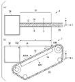
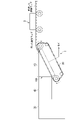
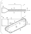
- FIG. 1 shows a fiber web forming apparatus, FIG. 1(a) being a top view and FIG. 1(b) being a side view.
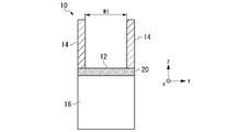
- FIG. 2 is a cross-sectional view of the dewatering channel provided in the fiber web forming apparatus shown in FIG. 1, taken along the line XX in FIG. 1(a).
- FIG. 3 is a side view of the fibrous web forming apparatus;
- FIG. 4 is a cross-sectional view of the dehydration channel.
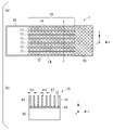
- FIG. 5 shows a fiber web forming apparatus having a vertical baffle arranged in a dewatering channel, FIG. 5(a) being a top view and FIG. 5(b) being taken along line XX of FIG. 5(a).
- 1 is a cross-sectional view in position; FIG.
- FIG. 6 is a cross-sectional view of the fiber web forming apparatus shown in FIG. 5.
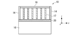
- FIG. FIG. 7 is a cross-sectional view of the dehydration channel.
- FIG. 8 is a cross-sectional view of a vertical current plate.
- FIG. 9 is a top view of a vertical current plate.
- FIG. 10 shows a fiber web forming apparatus having a horizontal baffle arranged in the dewatering channel, FIG. 10(a) being a top view and FIG. 10(b) being a sectional view.
- FIG. 11 is a cross-sectional view of the dehydration channel.
- FIG. 12 is a cross-sectional view of a horizontal current plate.
- FIG. 13 shows a configuration example of an oriented fiber web manufacturing apparatus.
- FIG. 13 shows a configuration example of an oriented fiber web manufacturing apparatus.
- FIG. 14 shows a configuration example of an oriented fiber web manufacturing apparatus.
- FIG. 15 shows a fiber web forming apparatus, FIG. 15(a) being a top view and FIG. 15(b) being a side view.
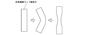
- FIG. 16 is a diagram illustrating the bending and stretching process for stretching a wet fibrous web.
- FIG. 17 shows the arrangement of the X-ray source, sample and X-ray detector in X-ray diffraction measurement.
- a method for producing an oriented fiber web includes (i) preparing a dewatering channel having an upstream end and a downstream end, which consists of a bottom surface, which is the surface of a papermaking net, and two side walls parallel to each other; (ii) introducing the fiber dispersion from the upstream end into the dewatering channel while running the papermaking net in the direction from the upstream end to the downstream end;
- FIGS. 1 and 2 An example configuration of a fibrous web forming apparatus that can be used in this method is shown in FIGS. 1 and 2.
- FIG. 1(a) and 1(b) are respectively a top view and a side view of the fibrous web forming apparatus, and FIG. - is a cross-sectional view at the position of the X-ray;
- the dewatering channel 10 provided in the fiber web forming apparatus 1 is composed of a bottom surface 12 and two side walls 14, and has an upstream end 10A and a downstream end 10B.
- a suction box 16 is arranged on the back side of the bottom surface 12 .
- the bottom surface 12 of the dewatering channel 10 is the surface of the papermaking net 20 .
- the papermaking net 20 is an endless belt, and forms the bottom surface 12 of the dehydration channel 10 in a section passing over the suction box 16 .
- the running direction of the papermaking net 20 in this section is hereinafter referred to as the M direction (Machine Direction).
- the T direction (Transverse Direction) which is the width direction of the papermaking net 20, is horizontal.
- the M direction is the direction from the upstream end 10A of the dewatering channel 10 to the downstream end 10B. Both side walls 14 of the dewatering channel 10 are parallel to the M direction.
- the bottom surface 12 of the dewatering channel 10 has an upward slope in the direction from the upstream end 10A to the downstream end 10B.
- the dehydration channel 10 may be closed by providing a ceiling plate. In this case, the water level of the fiber dispersion is set so that no water surface is formed below the ceiling plate.
- the fibrous web forming apparatus 1 further has a reservoir 30 coupled to the upstream end 10A of the dewatering channel 10.
- a reservoir 30 coupled to the upstream end 10A of the dewatering channel 10.
- Direct connection of the reservoir 30 to the dehydration channel 10 is not essential, and the connection between the dehydration channel 10 and the reservoir 30 may be indirect as described later.
- the fiber dispersion stored in the reservoir 30 is introduced into the dewatering channel 10 from the upstream end 10A and flows through the dewatering channel 10 toward the downstream end 10B.
- dewatering is performed by the action of the suction box 16 and a fiber web is formed on the papermaking net 20 .
- the suction box 16 can change the suction amount along the M direction. It is possible to prevent reverse flow toward the upstream end 10A side.
- the fiber dispersion liquid should form a stable laminar flow in the dewatering channel 10.
- the dewatering channel 10 should be designed so that the Reynolds number is as small as possible.
- One means of lowering the Reynolds number is to narrow the channel width W of the dewatering channel 10, ie the distance between the two side walls 14.
- FIG. It is known that a laminar flow is formed when the Reynolds number is 2300 or less. It is preferable to set the width W to 5 cm or less.
- the average flow velocity at the upstream end 10A that is, the volumetric flow rate of the fiber dispersion introduced into the dewatering channel 10 is determined by the interruption of the fiber dispersion flow at the upstream end 10A. A value divided by the area may be used.
- the channel width W of the dewatering channel 10 When the channel width W of the dewatering channel 10 is reduced, the ratio of the fibers that are stretched and oriented in the flow direction by the mechanism described above increases. This is because the closer to the side wall 14 , the greater the change in the flow velocity of the fiber dispersion depending on the distance to the side wall 14 .
- the width W of the dewatering channel 10 is increased in order to increase the width of the resulting fiber web, either one or both of the viscosity coefficient and the flow velocity of the fiber dispersion are adjusted so as to offset the accompanying increase in Reynolds number. should be changed. The higher the viscosity coefficient of the fiber dispersion and the lower the flow velocity, the lower the Reynolds number.
- the flow velocity of the fiber dispersion in the dewatering channel 10 decreases as the water depth D at the upstream end 10A of the dewatering channel 10 increases.
- the ratio (D/W) between the water depth D and the channel width W at the upstream end 10A of the dewatering channel 10 is 2 or more, 3 or more, 5 or more, 10 or more, 15 or more, 20 or more, 30 or more. could be.
- the inclination angle ⁇ of the bottom surface 12 of the dewatering channel 10 is preferably 5° or more, more preferably. is 10° or more, more preferably 15° or more, and may be 20° or more, further 25° or more.
- the slope angle ⁇ of the bottom surface 12 of the dewatering channel 10 is, for example, 45° or less, and may be 40° or less, or even 35° or less.
- the occurrence of local turbulence in the dehydration channel 10 should be suppressed as much as possible.
- a means for that purpose for example, as shown in cross section in FIG.
- a rectifying plate can be installed in the dewatering channel.
- 5 and 6 show an example of a fiber web forming apparatus in which straightening plates are installed in the dehydration channel.
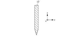
- a vertical straightening plate 17 is installed in the dehydration channel 10. As shown in FIG.
- the vertical straightening plate 17 has a vertical main surface (large area surface) and a normal to the main surface parallel to the T direction. As described above, the T direction is horizontal and perpendicular to the M direction. 5 and 6 omit the illustration of the support means for the vertical straightening plate 17, but the vertical straightening plate can be supported by an appropriate method.
- a plurality of rods can span between the two side walls 14 and each vertical baffle 17 can be supported by the plurality of rods.
- the vertical rectifying plates 17 may be fixed to each other by rods extending in the T direction.
- the length of the vertical straightening plate 17 is preferably substantially the same as the channel length L of the dehydration channel 10 .
- a gap is provided between the lower end of the vertical straightening plate 17 and the bottom surface 12 of the dewatering channel 10 .
- This gap is preferably constant along the M direction.
- This gap is preferably as narrow as possible within the range not less than the thickness of the fibrous web to be deposited on the bottom surface 12, and may be 20 mm or less, further 10 mm or less, further 5 mm or less, further 3 mm or less.
- the vertical straightening plate 17 is made of resin, metal, alloy, glass, ceramics, or a combination thereof, and has a thickness sufficient to ensure the rigidity required for a straightening plate.
- the rigidity required for the vertical straightening plate 17 varies depending on the capacity of the dewatering channel 10 and the flow velocity of the fiber dispersion. As long as the required rigidity is ensured, it is desirable that the thickness of the vertical straightening plate 17 is small.
- the plate thickness is preferably 10 mm or less, more preferably 5 mm or less, still more preferably 3 mm or less.
- the position of the upper end of the vertical straightening plate 17 is preferably at or above the water surface.
- the flow of the fiber dispersion in the dewatering channel 10 is divided into a plurality of parts by the vertical straightening plate 17 except for the vicinity of the bottom surface 12 .
- the dehydration channel 10 can be closed by arranging the ceiling plate 18.
- the upper end of the vertical straightening plate 17 can be connected to the ceiling plate 18 without a gap. preferable.
- the dewatering channel 10 is closed, the water level of the fiber dispersion is set so that no water surface is formed under the ceiling plate 18 .
- the spacing S11 between the side wall 14 and the vertical straightening plate 17 and the spacing S12 between the vertical straightening plates 17 are determined from the viewpoint of lowering the Reynolds number so that a laminar flow is formed. s, and if the flow velocity is 0.4 m/s, it is preferably 5 cm or less.
- the spacing S11 and the spacing S12 are preferably equal, and the spacing S12 is preferably the same between any two adjacent vertical rectifying plates 17 .
- the flow velocity of the fiber dispersion liquid changes greatly depending on the distance to the side wall 14 as it approaches the side wall 14 , and changes greatly depending on the distance to the vertical straightening plate 17 as it approaches the vertical straightening plate 17 . Therefore, the smaller the spacing S11 and the spacing S12, the more fibers will be stretched by the above mechanism and oriented in the direction of flow. For this reason, it is advantageous for the distance S11 and the distance S12 to be small, and they can be 4 cm or less, further 3 cm or less, further 2 cm or less, furthermore 1 cm or less.
- the vertical straightening plate 17 has a thickness, when the upstream side and the downstream side are compared with the lower end of the vertical straightening plate 17 as a reference, the effective cross-sectional area of the dewatering channel 10 is smaller on the upstream side.
- the lower end of the vertical straightening plate 17 means the end facing the bottom surface 12 of the dehydration channel 10 . Therefore, on the downstream side of the lower end of the vertical straightening plate 17, the flow velocity of the fiber dispersion liquid is lower than on the upstream side. In other words, a region where the flow velocity of the fiber dispersion decreases (hereinafter also referred to as a “flow velocity reduction region”) is formed immediately downstream of the lower end of the vertical straightening plate 17 .
- the spacing S11 and the spacing S12 are each preferably equal to or greater than the thickness of the vertical rectifying plate 17, more preferably twice or more. It is more preferable to make it 3 times or more. This is because the difference in the effective cross-sectional area of the dehydration channel 10 between the upstream side and the downstream side of the lower end of the vertical straightening plate 17 becomes smaller as the ratio of the spacing S11 and the spacing S12 to the thickness of the vertical straightening plate 17 increases. be.
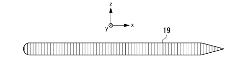
- the lower end of the vertical baffle plate 17 may be tapered as shown in FIG. 8 in order to avoid an abrupt drop in flow velocity in the flow velocity drop region.
- the surface of the tapered portion may be curved so that turbulence is less likely to occur.
- the vertical straightening plate 17 may have rounded corners on the upstream end as shown in FIG. 9 so that fibers are less likely to get caught on the upstream end.
- FIG. 10 and 11 show another example of a fiber web forming apparatus in which straightening plates are installed in the dehydration channel.
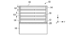
- the dehydration channel 10 is provided with a ceiling plate 18 and a horizontal straightening plate 19.
- the ceiling plate 18 and the horizontal current plate 19 have horizontal main surfaces (large-area surfaces), and the normals to the main surfaces are vertical lines. Both the ceiling plate 18 and the horizontal straightening plate 19 can be supported by fixing the ends in the T direction to the side walls 14 .
- the ceiling plate 18 is provided, the water level of the fiber dispersion is set so that a closed water channel is formed, in other words, no water surface is formed under the ceiling plate 18 . Installation of the ceiling plate 18 may be omitted.
- the ceiling plate 18 is made of resin, metal, alloy, glass, ceramics, or a combination of these, and has a thickness sufficient to ensure the rigidity required for a channel wall.
- the horizontal straightening plate 19 is made of resin, metal, alloy, or a combination thereof, and has a thickness sufficient to ensure the rigidity required for a straightening plate.
- the rigidity required for the ceiling plate 18 and the horizontal current plate 19 varies depending on the capacity of the dewatering channel 10 and the flow velocity of the fiber dispersion. As long as the necessary rigidity is ensured, it is desirable that the thickness of the horizontal straightening plate 19 is small.
- the plate thickness is preferably 10 mm or less, more preferably 5 mm or less, still more preferably 3 mm or less.
- the thickness of the ceiling plate 18 may be the same as that of the horizontal current plate 19, but is not limited.
- the upstream ends of the ceiling plate 18 and the horizontal straightening plate 19 are located at the upstream end 10A of the dehydration channel 10 .
- a gap is provided between the downstream end of the ceiling plate 18 and the bottom surface 12 of the dehydration channel 10 and between the downstream end of the horizontal straightening plate 19 and the bottom surface 12 of the dehydration channel 10 .
- This gap is preferably as narrow as possible within the range not less than the thickness of the fibrous web to be deposited on the bottom surface 12, and may be 20 mm or less, further 10 mm or less, further 5 mm or less, further 3 mm or less.
- the flow of the fiber dispersion in the dewatering channel 10 is divided into a plurality of parts by the vertical straightening plate 17 except for the vicinity of the bottom surface 12 .
- the spacing S21 between the ceiling plate 18 and the horizontal straightening plate 19 and the spacing S22 between the horizontal straightening plates 19 are determined from the viewpoint of lowering the Reynolds number so that a laminar flow is formed. ⁇ When the flow velocity is 0.4 m/s, it is preferably 5 cm or less.
- the spacing S21 and the spacing S22 are preferably equal, and the spacing S22 between any two adjacent horizontal current plates 19 is preferably the same.
- the flow velocity of the fiber dispersion changes greatly depending on the distance to the ceiling plate 18 as it approaches the ceiling plate 18, and also changes greatly depending on the distance to the horizontal straightening plate 19 as it approaches the horizontal straightening plate 19. . Therefore, as the space S21 between the ceiling plate 18 and the horizontal straightening plate 19 and the space S22 between the horizontal straightening plates 19 are made smaller, more fibers are stretched by the above mechanism and oriented in the flow direction. . For this reason, it is advantageous for the distance S21 and the distance S22 to be small, and they can be 4 cm or less, further 3 cm or less, further 2 cm or less, furthermore 1 cm or less.
- the spacing S21 and the spacing S22 are each preferably equal to or greater than the thickness of the horizontal rectifying plate 19, and preferably twice or more. It is more preferable, and more preferably 3 times or more.
- the horizontal straightening plate 19 may have rounded corners on the upstream end so that fibers are less likely to get caught on the upstream end.
- the downstream end may be tapered.
- the tapered portion may have a curved surface to reduce turbulence.
- the above-described vertical straightening plate and horizontal straightening plate can be combined to further subdivide the inside of the dehydration channel 10, thereby promoting the formation of laminar flow and the orientation of fibers thereby.
- the running speed of the papermaking net 20 is preferably 0.8 to 2.2 times the average flow speed, more preferably 1.1 to 1.9 times, still more preferably 1.4 to 1.6 times. is.
- the average flow velocity of the fiber dispersion at the upstream end 10A of the dewatering channel 10 means the volumetric flow rate of the fiber dispersion introduced into the dewatering channel 10, as described above. A value obtained by dividing by the cross-sectional area.
- the running speed of the papermaking net 20 is preferably 1 m/min or more, and within the range where the fiber dispersion does not become turbulent, 3 to 5 m/min, 5 to 10 m/min, 10 to 20 m/min. min, 20 to 40 m/min, 40 to 80 m/min, or the like.
- fibers that can be used in the fibrous web material include, but are not limited to, carbon fibers, inorganic fibers, metallic fibers and aramid fibers.
- the carbon fibers may include those recycled from carbon fiber waste or carbon fiber composite waste.
- Fibers selected from carbon fibers, inorganic fibers, metal fibers and aramid fibers may be used in combination with thermoplastic resin fibers.
- thermoplastic resin fibers are fibers made of heat-resistant thermoplastic resins such as engineering plastics, such as polycarbonate, polyamide, polyester, polyphenylene ether, polyetherimide, polyamideimide, polysulfone, polyethersulfone, polyether. Fibers made of ether ketone or polyphenylene sulfide.
- a fiber dispersion is a dispersion in which fibers are dispersed using water as a dispersion medium.
- a fiber dispersion can be prepared, for example, by adding a dispersant and fibers to an aqueous solution of a viscous agent, and diluting a stock solution with water.
- the method for preparing the fiber dispersion is not limited to this.
- the fiber length of the fibers contained in the fiber dispersion is preferably 100 mm or less, more preferably 75 mm or less, still more preferably 50 mm or less.
- the fibers contained in the fiber dispersion preferably contain a component with a fiber length of 3 mm or more, more preferably contain a component with a fiber length of 12 mm or more, and 95 wt% or more thereof have a fiber length in the range of 12 to 50 mm. It is more preferable to have Short fibers having a fiber length of 12 mm or more can be easily oriented by the above-described method, and the oriented state is relatively stable. However, when the content of fibers having a fiber length of more than 50 mm increases, the fibers are likely to be entangled with each other. Fiber-to-fiber entanglement degrades the appearance and/or quality of the fibrous web. Depending on the degree of entanglement of the fibers, it may cause clogging of the pump that delivers the fiber dispersion to the reservoir.
- a general papermaking viscous agent containing a water-soluble polymer such as polyethylene oxide or polyacrylamide as a component can be used.
- concentration of the viscous agent in the aqueous solution of the viscous agent may be determined according to the viscosity of the fiber dispersion to be prepared, and is not particularly limited, but can be, for example, about 0.3 wt%. According to the present inventor's experiments using carbon fiber, depending on the viscosity agent used, a large amount of fine bubbles are generated from the carbon fiber dispersion in the snake pump, so the combined use of an antifoaming agent is essential.
- Dispersants for example surfactants, are used to improve the dispersibility of fibers in water.
- the fiber content in the stock solution can be about 0.1 wt%, which can be diluted to give a fiber dispersion with a fiber content of 0.03 wt%.
- the oriented fiber web manufacturing apparatus includes a fiber web forming device 1 and a dryer 2 .
- a fiber web formed by the fiber web forming apparatus 1 is transferred to a felt (not shown) by a conventionally known means, and then sent to a dryer 2 to be dried.
- the dried fibrous web is, for example, wound onto a roll (not shown).
- the illustration of the system for supplying the fiber dispersion to the reservoir is omitted.
- FIG. 14 shows another example of an oriented fiber web manufacturing apparatus that can be used in the oriented fiber web manufacturing method according to the embodiment.
- the fiber web forming apparatus 1 is configured such that the fiber dispersion liquid is supplied from the reservoir 30 to the dewatering channel 10 through the introduction path 40 .
- the basic configuration of the oriented fiber web manufacturing apparatus shown in FIG. 14 is the same as that shown in FIG. Also in FIG. 14, the illustration of the system for supplying the fiber dispersion to the reservoir is omitted.
- the introduction channel 40 is a channel coupled to the upstream end 10A of the dewatering channel 10, and may be an open channel or a closed channel. When the dewatering channel 10 is a closed channel, it is preferable that the introduction channel 40 is also a closed channel, but this is not a limitation.
- the horizontal width and the depth of the dehydration channel 10 and the introduction channel 40 are made equal to each other, so that turbulent flow occurs in the dehydration channel 10 near the upstream end 10A. It is advantageous to make it difficult to generate Specifically, the horizontal width and depth of the dehydration channel 10 in the portion adjacent to the boundary between the dewatering channel 10 and the introduction channel 40 are each 0.9 of that of the introduction channel 40 in the portion adjacent to the boundary. It is preferably up to 1.1 times, more preferably 0.9 to 1 times, even more preferably 0.95 to 1 times.
- the fibers in the fiber dispersion can be oriented in the direction of flow, that is, in the direction from the reservoir 30 to the dewatering channel 10 in the introduction channel 40 as well.
- at least a portion of the introduction channel 40 including the boundary with the dewatering channel 10 preferably the entire area of the introduction channel 40
- the fiber dispersion forms a laminar flow the closer it gets to the channel wall, the lower the flow velocity, so a shearing force acts on the fibers dispersed in the fiber dispersion. As a result, the fibers are stretched and oriented in the direction of flow.
- Reducing the flow velocity of the fiber dispersion works to reduce the Reynolds number, which is advantageous for forming a laminar flow, but also works to reduce the productivity of the fiber web. Therefore, it is necessary to devise ways to promote the formation of a laminar flow without lowering the flow velocity of the fiber dispersion.
- the vertical straightening plate When the vertical straightening plate is installed in the dehydration channel 10 as in the above example, the vertical straightening plate is placed in the introduction channel 40 so that the upstream end of the vertical straightening plate is positioned in the introduction channel 40. It is preferable to extend to the inside. Similarly, when a horizontal straightening plate is installed in the dehydration channel 10, the horizontal straightening plate is extended into the introduction passage 40 so that the upstream end of the horizontal straightening plate is positioned in the introduction passage 40. is preferred.
- the flow channel wall In order to suppress the occurrence of turbulent flow, it is advantageous for the flow channel wall to have a flat surface. Therefore, the surface roughness Rz of the inner surface of the introduction path 40 is preferably 5 ⁇ m or less. Similarly to the dehydration channel, in the introduction channel, curving the inner surface of the side wall toward the inside of the channel at the portion adjacent to the bottom is advantageous in preventing the occurrence of turbulent flow.
- the portion where the flow velocity decreases from the upstream side to the downstream side is the portion where the cross-sectional area of the channel increases, specifically, the portion where either one or both of the width and depth of the channel increases. is.
- providing the introduction path with a portion where the flow velocity increases from the upstream side to the downstream side is advantageous in promoting the orientation along the flow direction of the fibers in the fiber dispersion. This is because the fibers are pulled in the flow direction at such portions.
- the wet fibrous web conveyed between the fibrous web forming apparatus and the dryer may be stripped from the felt and stretched in the MD direction.
- the fibers constituting the fibrous web can be more strongly oriented in the MD direction.
- the MD direction of the fibrous web refers to the direction parallel to the M direction when the fibrous web was formed on the papermaking net.
- the TD direction of the fibrous web is referred to as the TD direction of the fibrous web.
- the conveying direction is the same as the MD direction.
- the wet fiber web does not tear easily and can be stretched in the MD direction until the length becomes more than twice its original length. The reason for this is presumed to be that the action of water causes capillary attraction between fibers and reduces friction between fibers.
- the fibrous web once dried, may be rewetted with a liquid and then stretched in the MD.
- Any liquid may be used as long as it has the effect of generating capillary attraction between fibers and reducing friction between fibers.
- liquids include water, organic solvents, and mixtures of water and organic solvents.
- the liquid may have dissolved solutes, suspended particulates, or both.
- the fibrous web consists of carbon fibers
- the liquid may be a suspension in which a sizing agent for carbon fibers is dispersed. After drawing, the fibrous web is dried again.
- thermosetting prepreg can be obtained by impregnating an oriented fiber web manufactured using reinforcing fibers as a raw material with a thermosetting resin composition. Thermosetting prepreg is used as an intermediate material when manufacturing FRP (fiber reinforced plastic) products.
- thermoplastic prepreg can be obtained by impregnating an oriented fiber web produced using reinforcing fibers as a raw material with a thermoplastic resin composition. Thermoplastic prepregs are used as intermediate materials when manufacturing FRTP (fiber reinforced thermoplastic) products.
- fibers for the reinforcing material and thermoplastic resin fibers for the matrix resin are used as raw materials, and an oriented fiber web in which these fibers are mixed can be manufactured by the manufacturing method according to the embodiment.
- the oriented fiber web is heated under pressure to a temperature at which the thermoplastic resin fibers melt, the thermoplastic resin fibers melt to provide a FRTP consisting of a matrix of thermoplastic resin and reinforcing fibers.
- Embodiments 1 described the following techniques (1) and (2) for enhancing the orientation of the fibers that make up the fiber web.
- (1) A technique in which a wet-formed fibrous web is stretched in a wet state before drying and dried after stretching.
- (2) A technique in which a dried fibrous web is wetted with a liquid, stretched while still wet, and dried again after stretching.
- the fiber length of the fibers contained in the fibrous web is preferably 100 mm or less, more preferably 75 mm or less, even more preferably 50 mm or less.
- the fibers contained in the fibrous web preferably contain a component with a fiber length of 3 mm or more, more preferably contain a component with a fiber length of 12 mm or more, and 95 wt% or more thereof have a fiber length in the range of 12 to 50 mm. It is more preferable to have
- a method for producing an oriented fiber web which is a fiber web in which fibers are oriented in a specific direction, comprising: (i) a bottom surface, which is the surface of a papermaking net, and two side walls parallel to each other; and (ii) running the papermaking net in a direction from the upstream end to the downstream end, and dispersing the fiber dispersion using water as a dispersion medium at the upstream end.
- the bottom surface of the dewatering channel has an upward slope in the direction from the upstream end to the downstream end, and the fiber dispersion in the dewatering channel flows from the upstream A manufacturing method, wherein a fibrous web is formed by dewatering while flowing in a direction from an end toward the downstream end.
- the upward slope is 5° or more, 10° or more, 15° or more, 20° or more, or 25° or more.
- the upward slope is 45° or less, 40° or less, or 35° or less.
- the ratio D/W of the water depth D at the upstream end of the dewatering channel to the channel width W of the dewatering channel is 2 or more, 3 or more, 5 or more, 10 or more, 15 or more, 20 or more, or The manufacturing method according to any one of Embodiments 1 to 3, which is 30 or more.
- a rectifying plate is installed in the dewatering channel.
- the rectifying plate has rounded corners at the ends on the upstream side.
- Embodiment 7 The manufacturing method according to Embodiment 5 or 6, wherein the rectifying plate is a vertical rectifying plate.
- Embodiment 8 A manufacturing method according to Embodiment 7, wherein the lower end of the vertical current plate is tapered.
- Embodiment 9 The manufacturing method according to Embodiment 7 or 8, wherein the gap between the lower end of the vertical current plate and the bottom surface of the dewatering channel is 20 mm or less, 10 mm or less, 5 mm or less, or 3 mm or less.
- a plurality of the vertical straightening plates are installed in the dewatering channel, the thickness of the plurality of the vertical straightening plates is the same, and the thickness of the plurality of the vertical straightening plates is the same.
- the distance between any two adjacent ones and the distance between the side wall and the vertical rectifying plate closest to it are both equal to or greater than the thickness of the vertical rectifying plate, twice or more, or three times or more.
- a plurality of vertical straightening plates are installed in the dehydration channel, and the distance between any two adjacent vertical straightening plates among the plurality of vertical straightening plates, and the side wall and the closest one to it 11.
- a plurality of horizontal straightening plates are installed in the dewatering channel, the thickness of the plurality of horizontal straightening plates is the same, and the thickness of the plurality of horizontal straightening plates is the same. 15. The manufacturing method according to any one of Embodiments 12 to 14, wherein the interval between any two adjacent plates is equal to or greater than, two times or greater, or three times or greater the thickness of the horizontal current plate.
- a plurality of horizontal straightening plates are installed in the dewatering channel, and the distance between any two adjacent horizontal straightening plates among the plurality of horizontal straightening plates is 4 cm or less, 3 cm or less, or 2 cm. 16.
- the running speed of the papermaking net in the dewatering channel is 0.8 to 2.2 times the average flow speed of the fiber dispersion at the upstream end of the dewatering channel, preferably 1.1 times. 1.9 times, more preferably 1.4 to 1.6 times.
- the horizontal width and depth of the dehydration channel in the portion adjacent to the boundary between the dewatering channel and the introduction channel are each 0.00% of that of the introduction channel in the portion adjacent to the boundary.
- Embodiment 23 The manufacturing method according to Embodiment 21 or 22, wherein the fibers in the fiber dispersion are oriented in the flow direction in the introduction path.
- Embodiment 24 The production method according to any one of Embodiments 1 to 23, wherein the fibers contained in the fiber dispersion have a fiber length of 100 mm or less, preferably 75 mm or less, more preferably 50 mm or less.
- Embodiment 25 A method according to Embodiment 24, wherein the fibers comprise a component with a fiber length of 3 mm or more, preferably a component with a fiber length of 12 mm or more.
- the fibers comprise a component with a fiber length of 3 mm or more, preferably a component with a fiber length of 12 mm or more.
- the fibers comprise one or more fibers selected from carbon fibers, inorganic fibers, metal fibers and aramid fibers.
- Embodiment 28 The manufacturing method according to Embodiment 27, wherein the fibers comprise carbon fibers and the fiber dispersion comprises polyacrylamide.
- Embodiment 29 A method according to any one of Embodiments 1 to 27, wherein the fiber dispersion comprises a viscosity agent and optionally a surfactant.
- Embodiment 30 A method according to Embodiment 27 or 28, wherein said fibers further comprise thermoplastic resin fibers.
- Emodiment 32 A method according to Embodiment 31, comprising stretching the fibrous web in a wet state prior to said drying.
- Embodiment 31 comprising re-wetting the fibrous web with a liquid after said drying and stretching while still wet, and re-drying said fibrous web after said stretching.
- a dehydration channel is provided which consists of a bottom surface which is the surface of a papermaking net and two side walls parallel to each other and which has an upstream end and a downstream end, and the papermaking net is directed from the upstream end to the downstream end.
- a fiber dispersion containing water as a dispersion medium is introduced from the upstream end into the dewatering channel while running in the direction, and dewatered while flowing in the dewatering channel in the direction from the upstream end to the downstream end.
- a fibrous web forming apparatus wherein the bottom surface of the dewatering channel slopes upward in a direction from the upstream end to the downstream end.
- a fiber web forming apparatus according to Embodiment 34 wherein the upward slope is 5° or more, 10° or more, 15° or more, 20° or more, or 25° or more.
- a fibrous web forming apparatus according to Embodiment 35 wherein the upward slope is 45° or less, 40° or less, or 35° or less.
- the ratio D/W of the water depth D at the upstream end of the dewatering channel to the channel width W of the dewatering channel is 2 or more, 3 or more, 5 or more, 10 or more, 15 or more, 20 or more, or 37.
- the fibrous web forming apparatus according to any of embodiments 34-36 which is 30 or more.
- the fiber web forming apparatus according to any one of Embodiments 34 to 36 which has a current plate installed in the dehydration channel.
- Embodiment 40 A fiber web forming apparatus according to Embodiment 38 or 39, wherein the rectifying plate is a vertical rectifying plate.
- Embodiment 41 A fiber web forming apparatus according to Embodiment 40, wherein the lower end of the vertical baffle is tapered.
- Embodiment 42 A fiber web forming apparatus according to Embodiment 40 or 41, wherein the gap between the lower end of the vertical current plate and the bottom surface of the dewatering channel is 20 mm or less, 10 mm or less, 5 mm or less, or 3 mm or less.
- Emodiment 43 having a plurality of said vertical rectifiers, the thickness of said plurality of said vertical rectifiers being the same, the interval between any two adjacent ones of said plurality of said vertical rectifiers, and 43.
- a plurality of said vertical rectifiers are provided, and the distance between any two adjacent vertical rectifiers out of said plurality of said vertical rectifiers and the distance between said side walls and said vertical rectifiers closest thereto is 4 cm or less, 3 cm or less, 2 cm or less, or 1 cm or less.
- Embodiment 45 A fiber web forming apparatus according to Embodiment 38 or 39, wherein the current plate is a horizontal current plate.
- Embodiment 46 A fiber web forming apparatus according to embodiment 45, wherein the downstream end of the horizontal baffle is tapered.
- Embodiment 47 The fiber web according to Embodiment 45 or 46, wherein the gap between the downstream end of the horizontal current plate and the bottom surface of the dewatering channel is 20 mm or less, 10 mm or less, 5 mm or less, or 3 mm or less. forming device.
- a plurality of horizontal straightening plates are provided, the thicknesses of the plurality of horizontal straightening plates are the same, and the interval between any two adjacent horizontal straightening plates among the plurality of horizontal straightening plates is 48.
- the fibrous web forming apparatus according to any one of embodiments 45 to 47, wherein the thickness is equal to or greater than, 2 times or greater, or 3 times or greater than the thickness of the horizontal baffle.
- a fibrous web forming apparatus according to any one of aspects 45-47.
- Embodiment 50 The fiber web forming apparatus according to any one of Embodiments 34 to 49, which has a ceiling plate installed in the dewatering channel.
- Embodiment 51 A fibrous web forming apparatus according to any one of Embodiments 34 to 50, wherein the inner surface of the sidewall is curved inwardly at a portion adjacent to the bottom surface.
- Embodiment 52 The fiber dispersion of Embodiments 34 to 51, further comprising an introduction channel coupled to the upstream end of the dewatering channel, and supplying the fiber dispersion to the dewatering channel through the introduction channel.
- a fiber web forming apparatus according to any one of the above.
- the horizontal width and depth of the dehydration channel in the portion adjacent to the boundary between the dewatering channel and the introduction channel are each 0.00% of that of the introduction channel in the portion adjacent to the boundary.
- a fibrous web forming apparatus according to embodiment 52 which is 9-1.1 times, preferably 0.9-1 times, more preferably 0.95-1 times.
- An oriented fiber web manufacturing apparatus comprising the fiber web forming apparatus according to any one of Embodiments 34 to 53 and a dryer for drying the fiber web formed by the fiber web forming apparatus.
- a method for producing an oriented fibrous web which is a fibrous web in which fibers are oriented in a specific direction, comprising forming a fibrous web by a wet method, drying the fibrous web, and and drawing said fibrous web while still wet.
- a method for producing an oriented fiber web which is a fiber web in which fibers are oriented in a specific direction, comprising forming a fiber web by a wet method, drying the fiber web, and after the drying, A method of manufacturing comprising re-wetting a fibrous web with a liquid and stretching the fibrous web while still wet, and re-drying the fibrous web after said stretching.
- a method for producing an oriented fiber web which is a fiber web in which fibers are oriented in a specific direction, comprising the steps of moistening a dried fiber web with a liquid and stretching it in a wet state; and drying the fibrous web after.
- Embodiment 59 A method according to Embodiment 58, wherein the fibers contained in the oriented fibrous web comprise a component with a fiber length of 3 mm or more, preferably a component with a fiber length of 12 mm or more.
- Embodiment 60 A manufacturing method according to Embodiment 59, wherein 95 wt% or more of the fibers contained in the oriented fiber web have a fiber length within the range of 12 to 50 mm.
- the oriented fibrous web comprises one or more fibers selected from carbon fibres, inorganic fibres, metallic fibres, and aramid fibres.
- Embodiment 62 The method of manufacturing according to Embodiment 61, wherein said oriented fibrous web further comprises thermoplastic resin fibers.
- Embodiment 63 Manufacturing an oriented fiber web by the manufacturing method according to any one of Embodiments 1 to 33 and 55 to 62, and impregnating the oriented fiber web with a thermosetting resin composition or a thermoplastic resin composition.
- a method of manufacturing a prepreg comprising:
- Experiment 1 A sheet obtained by impregnating a fiber mat consisting of a carbon fiber bundle (TR50S15L manufactured by Mitsubishi Chemical Corporation) having 15,000 filaments cut to a length of 25 mm with a thermosetting resin composition containing a vinyl ester resin, an unsaturated polyester resin and styrene.
- a molding compound (SMC) was prepared. Using an electric furnace, this SMC was first heated in an oxygen-free atmosphere and then in an oxygen-containing atmosphere to decompose and remove the resin component, thereby obtaining cotton-like recycled carbon fibers.
- the viscosity coefficient of the fiber dispersion was measured at a rotational speed of 100 rpm and a spindle of S61, and found to be 0.02 Pa ⁇ s.
- a carbon fiber web having a width of 2 cm was continuously formed on a papermaking net running at 3 m/min. deposited on.
- the width of the dewatering channel was 2 cm, and the upward slope angle of the bottom surface of the dewatering channel was 20°.
- the water depth of the fiber dispersion at the upstream end of the dewatering channel when the fiber dispersion was supplied at the above flow rate was 250 mm. Therefore, the average flow velocity of the fiber dispersion at the upstream end was calculated to be 1.9 m/min.
- the width (dimension in the TD direction) of the carbon fiber web measured after air drying was 2 cm, and the basis weight was 33 g/m 2 .
- the thickness measured at a load of 500 g/cm 2 using a dial gauge (Mitutoyo ABS Digimatic Indicator ID-CX) equipped with a flat probe with a diameter of 5 mm was 0.19 mm. was calculated to be 0.17 g/cm 3 .
- Experiment 2 A strip of carbon fiber web having a length of 12 cm and a width of 2 cm cut out from the carbon fiber web prepared in Experiment 1 was impregnated with water of the same weight as the strip, and then the strip was cut in the length direction ( It was stretched in the MD direction). As shown in FIG. 16, when one side in the width direction (TD direction) was first stretched and bent to the other side, and then the other side was stretched and straightened back, the strip of the carbon fiber web was stretched without being torn apart. . The stretched portion was constricted and narrowed.
- the length of the strip of carbon fiber web was doubled.
- the basis weight and thickness of the stretched portion of the strip of carbon fiber web were measured in the same manner as in Experiment 1.
- the basis weight was 58 g/m 2 and the thickness was 0.13 mm.
- the bulk density was calculated from the value of , it was 0.43 g/cm 3 .
- Experiment 3 An attempt was made to stretch the strips in the same manner as in Experiment 2, except that the amount of water impregnated into the strips of carbon fiber web was varied, with the following results. Stretching was as easy as Experiment 2 even when the amount of water was increased to four times the weight of the strip. When the amount of water was 8 times the weight of the strip, the strip became quite soft and could be torn apart unless the strip was carefully bent and stretched, but stretching was possible. When 10 times its weight of water was dropped onto the strip of carbon fiber web, the strip did not soak completely, but rather, the strip appeared to be submerged in water. If the sheet was bent and stretched in this state, the elongated pieces were torn off, and the sheet could not be stretched.
- the degree of orientation fa of each sample was calculated from the following formulas (1) and (2) (Herman's method).
- I( ⁇ ) is the intensity of the graphite 002 diffraction line when the rotation angle of the sample is ⁇ .
- the plane containing the X-ray source, rotation axis of the sample, and X-ray detector is 0° when the plane including the sample is perpendicular to the MD direction of the sample.
- ⁇ is set to 0° when the same plane is perpendicular to the fiber direction of the sample.
- the value that the orientation degree f a can take is within the range of -1 to 1, and when ⁇ is 0°, it approaches 1 when the fiber orientation is biased in the direction orthogonal to the above plane, and when ⁇ is 0°, the above It approaches -1 when the fiber orientation is biased in the direction parallel to the plane.
- the degree of orientation fa approaches 0 as the randomness of the fiber orientation increases. The results are summarized in Table 1 below.
- Fiber web forming device 2 Dryer 10 Dehydration channel 10A Upstream end 10B Downstream end 12 Bottom surface 14 Side wall 16 Suction box 17 Vertical straightening plate 18 Ceiling plate 19 Horizontal straightening plate 20 Paper making net 30 Reservoir 40 Introduction path
Landscapes
- Chemical & Material Sciences (AREA)
- Inorganic Chemistry (AREA)
- Paper (AREA)
Abstract
繊維が特定方向に配向した配向繊維ウェブを湿式法で製造する技術に関する改良を提供する。配向繊維ウェブ製造方法は、(i)抄紙網の表面である底面と、互いに平行な2つの側壁とからなり、上流端および下流端を有する脱水流路を準備すること、および、(ii)前記抄紙網を前記上流端から前記下流端に向かう方向に走行させながら、繊維分散液を前記上流端から前記脱水流路内に導入することを含む。脱水流路の底面は上流端から下流端に向かう方向に上り勾配を有する。脱水流路では繊維分散液が上流端から下流端に向かう方向に流れながら脱水されることにより繊維ウェブが形成される。
Description
本発明は、主として、配向繊維ウェブの製造方法、繊維ウェブ形成装置および配向繊維ウェブ製造装置に関する。
本願は、2021年5月25日に、日本に出願された特願2021-087588号に基づき優先権を主張し、その内容をここに援用する。
本願は、2021年5月25日に、日本に出願された特願2021-087588号に基づき優先権を主張し、その内容をここに援用する。
配向繊維ウェブ、すなわち繊維が特定方向に配向した繊維ウェブを、湿式法(抄造法)で製造することを含む、繊維強化熱可塑性樹脂シート(熱可塑性プリプレグ)の製造方法が提案されている(特許文献1)。
配向繊維ウェブを湿式法で製造する技術に関しては、改良の余地が残されている。
本発明の一態様は、湿式法を用いた配向繊維ウェブの製造効率の改善を目的としている。
本発明の他の一態様は、繊維が強く配向した配向繊維ウェブを製造するための技法を提供することを目的としている。
本発明の一態様は、湿式法を用いた配向繊維ウェブの製造効率の改善を目的としている。
本発明の他の一態様は、繊維が強く配向した配向繊維ウェブを製造するための技法を提供することを目的としている。
本発明の一実施形態によれば、繊維が特定方向に配向した繊維ウェブである配向繊維ウェブの製造方法であって、(i)抄紙網の表面である底面と、互いに平行な2つの側壁とからなり、上流端および下流端を有する脱水流路を準備すること、および、(ii)前記抄紙網を前記上流端から前記下流端に向かう方向に走行させながら、水を分散媒とする繊維分散液を前記上流端から前記脱水流路内に導入することを含み、前記脱水流路の前記底面は前記上流端から前記下流端に向かう方向に上り勾配を有し、前記脱水流路で前記繊維分散液が前記上流端から前記下流端に向かう方向に流れながら脱水されることにより繊維ウェブが形成される、製造方法が提供される。
本発明の他の一実施形態によれば、抄紙網の表面である底面と、互いに平行な2つの側壁とからなり、上流端および下流端を有する脱水流路を備え、前記抄紙網を前記上流端から前記下流端に向かう方向に走行させつつ、水を分散媒とする繊維分散液を前記上流端から前記脱水流路内に導入し、前記脱水流路内を前記上流端から前記下流端に向かう方向に流しながら脱水させることができ、前記脱水流路の前記底面は前記上流端から前記下流端に向かう方向に上り勾配を有している、繊維ウェブ形成装置が提供される。
本発明の更に他の一実施形態によれば、繊維が特定方向に配向した繊維ウェブである配向繊維ウェブの製造方法であって、湿式法で繊維ウェブを形成することと、前記繊維ウェブを乾燥させることと、前記乾燥の前に前記繊維ウェブを湿った状態のまま延伸させることとを含む製造方法が提供される。
本発明の更に他の一実施形態によれば、繊維が特定方向に配向した繊維ウェブである配向繊維ウェブの製造方法であって、湿式法で繊維ウェブを形成することと、前記繊維ウェブを乾燥させることと、前記乾燥の後に繊維ウェブを液体で再度湿らせたうえ、湿った状態のまま延伸させることと、前記延伸の後に前記繊維ウェブを再度乾燥させることとを含む製造方法が提供される。
本発明の更に他の一実施形態によれば、繊維が特定方向に配向した繊維ウェブである配向繊維ウェブの製造方法であって、乾燥した繊維ウェブを液体で湿らせたうえ、湿った状態のまま延伸させることと、前記延伸の後に前記繊維ウェブを乾燥させることとを含む製造方法が提供される。
好ましい実施形態によれば、配向繊維ウェブを湿式法で製造する技術に関する改良が提供される。
1.配向繊維ウェブの製造方法
本発明の一実施形態は配向繊維ウェブの製造方法に関する。
実施形態に係る配向繊維ウェブ製造方法は、(i)抄紙網の表面である底面と、互いに平行な2つの側壁とからなり、上流端および下流端を有する脱水流路を準備すること、および、(ii)前記抄紙網を前記上流端から前記下流端に向かう方向に走行させながら、繊維分散液を前記上流端から前記脱水流路内に導入することを含む。
この方法で使用され得る繊維ウェブ形成装置の構成例を図1および図2に示す。図1(a)および図1(b)は、それぞれ、繊維ウェブ形成装置の上面図および側面図であり、図2は、繊維ウェブ形成装置が備える脱水流路の、図1(a)のX-X線の位置における断面図である。
図1および図2を参照すると、繊維ウェブ形成装置1が備える脱水流路10は、底面12と2つの側壁14とから構成され、上流端10Aと下流端10Bを有している。底面12の裏側には吸引ボックス16が配置されている。
脱水流路10の底面12は、抄紙網20の表面である。抄紙網20は無端ベルトであり、吸引ボックス16上を通過する区間において、脱水流路10の底面12を構成している。この区間における抄紙網20の走行方向のことを以下ではM方向(Machine Direction)と呼ぶ。抄紙網20の幅方向であるT方向(Transverse Direction)は水平である。
M方向は、脱水流路10の上流端10Aから下流端10Bに向かう方向である。脱水流路10の2つの側壁14はいずれも、M方向に平行である。
脱水流路10の底面12は、上流端10Aから下流端10Bに向かう方向に上り勾配を有している。
脱水流路10は、天井板を設けることにより閉水路としてもよい。その場合、天井板の下方に水面が形成されないように繊維分散液の水位が設定される。
繊維ウェブ形成装置1は、更に、脱水流路10の上流端10Aに結合されたリザーバー30を有する。脱水流路10にリザーバー30を直接結合させることは必須ではなく、後述するように、脱水流路10とリザーバー30の結合は間接的であってもよい。
図3に示すように、リザーバー30に貯留された繊維分散液は、上流端10Aから脱水流路10に導入され、脱水流路10内を下流端10Bに向かって流れる。その間に、吸引ボックス16の働きにより脱水が行われ、抄紙網20上に繊維ウェブが形成される。
吸引ボックス16は、M方向に沿って吸引量を変えることが可能であり、例えば、下流端10B側に向かって吸引量を多くしていくことにより、脱水流路10内での繊維分散液が上流端10A側に向かって逆流するのを防ぐことができる。
図3に示すように、リザーバー30に貯留された繊維分散液は、上流端10Aから脱水流路10に導入され、脱水流路10内を下流端10Bに向かって流れる。その間に、吸引ボックス16の働きにより脱水が行われ、抄紙網20上に繊維ウェブが形成される。
吸引ボックス16は、M方向に沿って吸引量を変えることが可能であり、例えば、下流端10B側に向かって吸引量を多くしていくことにより、脱水流路10内での繊維分散液が上流端10A側に向かって逆流するのを防ぐことができる。
脱水流路10内を繊維分散液が渦巻くことなく流れるとき、すなわち、層流をなして流れるとき、その流速は側壁14に近づくほど下がる。従って、繊維分散液中に分散された繊維にはせん断力が作用する。このせん断力の作用で、繊維は流動方向に沿って引き伸ばされるとともに、繊維方向が流動方向と一致するように配向する。
したがって、脱水流路10内を上流端10Aから下流端10Bに向かうように繊維分散液を流したときには、M方向に繊維が配向した繊維ウェブが抄紙網20上に堆積する。
したがって、脱水流路10内を上流端10Aから下流端10Bに向かうように繊維分散液を流したときには、M方向に繊維が配向した繊維ウェブが抄紙網20上に堆積する。
繊維がM方向に配向した繊維ウェブを安定的に抄紙網20上に堆積させるには、脱水流路10内で繊維分散液が安定した層流を形成するようにすればよい。つまり、レイノルズ数ができるだけ小さくなるように脱水流路10を設計すればよい。
レイノルズ数を下げるひとつの手段は、脱水流路10の流路幅W、すなわち2つの側壁14間の間隔を狭くすることである。層流はレイノルズ数が2300以下のとき形成されることが知られているので、例えば繊維分散液の粘性係数が0.01Pa・s、流速が0.4m/sの場合であれば、流路幅Wを5cm以下とすることが好ましい。
脱水流路10内における繊維分散液の流速の目安として、上流端10Aにおける平均流速、すなわち、脱水流路10に導入される繊維分散液の体積流量を、上流端10Aにおける繊維分散液流の断面積で除算した値を用いてもよい。
レイノルズ数を下げるひとつの手段は、脱水流路10の流路幅W、すなわち2つの側壁14間の間隔を狭くすることである。層流はレイノルズ数が2300以下のとき形成されることが知られているので、例えば繊維分散液の粘性係数が0.01Pa・s、流速が0.4m/sの場合であれば、流路幅Wを5cm以下とすることが好ましい。
脱水流路10内における繊維分散液の流速の目安として、上流端10Aにおける平均流速、すなわち、脱水流路10に導入される繊維分散液の体積流量を、上流端10Aにおける繊維分散液流の断面積で除算した値を用いてもよい。
脱水流路10の流路幅Wを小さくしたとき、前述のメカニズムによって流動方向に引き伸ばされ、配向する繊維の割合が増加する。側壁14に近づくほど、繊維分散液の流速が側壁14までの距離に依存して大きく変化するからである。
得られる繊維ウェブの幅を広げるために脱水流路10の幅Wを広げる場合には、それに伴うレイノルズ数の増加が相殺されるように、繊維分散液の粘性係数と流速のいずれか一方または両方を変化させることが望ましい。繊維分散液の粘性係数を高くするほど、また、流速を低下させるほど、レイノルズ数は低下する。
得られる繊維ウェブの幅を広げるために脱水流路10の幅Wを広げる場合には、それに伴うレイノルズ数の増加が相殺されるように、繊維分散液の粘性係数と流速のいずれか一方または両方を変化させることが望ましい。繊維分散液の粘性係数を高くするほど、また、流速を低下させるほど、レイノルズ数は低下する。
脱水流路10に一定の体積流量で繊維分散液を導入する場合、脱水流路10の上流端10Aにおける水深Dが大きいほど、脱水流路10内における繊維分散液の流速は低くなる。このことは、レイノルズ数の上昇を避けながら、繊維ウェブの製造効率を上げるうえで、脱水流路10の上流端Aにおける水深Dを大きくすることが有利であることを意味する。
例えば、脱水流路10の上流端10Aにおける水深Dと流路幅Wとの比率(D/W)は、2以上、3以上、5以上、10以上、15以上、20以上、30以上などであり得る。
例えば、脱水流路10の上流端10Aにおける水深Dと流路幅Wとの比率(D/W)は、2以上、3以上、5以上、10以上、15以上、20以上、30以上などであり得る。
脱水流路10の流路長Lを大きくし過ぎることなく上流端10Aにおける十分な水深Dを確保するために、脱水流路10の底面12の勾配角θは、好ましくは5°以上、より好ましくは10°以上、更に好ましくは15°以上であり、20°以上、更には25°以上であってもよい。
勾配角θが大き過ぎるとき、脱水流路10内の繊維分散液の流れを底面12の近傍において定常的にM方向と平行、つまり、上流端10A側から下流端10Bに向かう方向に保つことが難しくなる傾向がある。従って、脱水流路10の底面12の勾配角θは、例えば45°以下であり、40°以下、更には35°以下であってもよい。
勾配角θが大き過ぎるとき、脱水流路10内の繊維分散液の流れを底面12の近傍において定常的にM方向と平行、つまり、上流端10A側から下流端10Bに向かう方向に保つことが難しくなる傾向がある。従って、脱水流路10の底面12の勾配角θは、例えば45°以下であり、40°以下、更には35°以下であってもよい。
脱水流路10内における局所的な乱流の発生は可能な限り抑制すべきである。そのための手段として、例えば、図4に断面を示すように、底面12と隣接する部分において側壁14の内面を流路の内側に湾曲させることができる。
脱水流路の流路幅を広げ、より幅広の繊維ウェブの形成を可能とするために、脱水流路内に整流板を設置することができる。
脱水流路内に整流板を設置した繊維ウェブ形成装置の一例を図5および図6に示す。
図5および図6を参照すると、脱水流路10内に垂直整流板17が設置されている。垂直整流板17は、主面(大面積表面)が垂直であり、主面の法線がT方向と平行である。T方向は前述の通り、水平であり、かつ、M方向に垂直である。
図5および図6では垂直整流板17の支持手段の図示を省略しているが、垂直整流板の適宜な方法で支持することができる。例えば、複数のロッドを2つの側壁14の間に架け渡し、その複数のロッドによって各垂直整流板17を支持することができる。垂直整流板17のばたつきを抑えるために、垂直整流板17同士をT方向に延びるロッドで互いに固定してもよい。
垂直整流板17の長さは、好ましくは、脱水流路10の流路長Lと略同じである。垂直整流板17の下端と脱水流路10の底面12との間には隙間が設けられる。この隙間は、M方向に沿って一定であることが好ましい。この隙間は、底面12上に堆積させるべき繊維ウェブの厚さ以下とならない範囲内において、狭い程好ましく、20mm以下、更には10mm以下、更には5mm以下、更には3mm以下であり得る。
垂直整流板17は、樹脂、金属、合金、ガラス、セラミックスまたはこれらの組合せからなり、整流板として必要な剛性が確保できるだけの厚さを有する。脱水流路10の容量や繊維分散液の流速に応じて、垂直整流板17に要求される剛性は異なる。必要な剛性が確保される限りにおいて、垂直整流板17の板厚は小さい方が望ましい。該板厚は、好ましくは10mm以下、より好ましくは5mm以下、更に好ましくは3mm以下である。
垂直整流板17は、樹脂、金属、合金、ガラス、セラミックスまたはこれらの組合せからなり、整流板として必要な剛性が確保できるだけの厚さを有する。脱水流路10の容量や繊維分散液の流速に応じて、垂直整流板17に要求される剛性は異なる。必要な剛性が確保される限りにおいて、垂直整流板17の板厚は小さい方が望ましい。該板厚は、好ましくは10mm以下、より好ましくは5mm以下、更に好ましくは3mm以下である。
垂直整流板17の上端の位置は、脱水流路10を開水路とする場合には、水面と同じか水面より上であることが好ましい。言い換えれば、脱水流路10内における繊維分散液の流れは、底面12の近傍を除き、垂直整流板17によって複数に分割されることが好ましい。
一例では、図7に示すように天井板18を配置して脱水流路10を閉水路とすることができ、その場合には、垂直整流板17の上端を天井板18と隙間なくつなげることが好ましい。脱水流路10を閉水路とするときは、天井板18の下に水面が形成されないように、繊維分散液の水位が設定される。
一例では、図7に示すように天井板18を配置して脱水流路10を閉水路とすることができ、その場合には、垂直整流板17の上端を天井板18と隙間なくつなげることが好ましい。脱水流路10を閉水路とするときは、天井板18の下に水面が形成されないように、繊維分散液の水位が設定される。
側壁14と垂直整流板17の間隔S11、および、垂直整流板17同士の間隔S12は、層流が形成されるようにレイノルズ数を下げる観点から、例えば繊維分散液の粘性係数が0.01Pa・s、流速が0.4m/sの場合であれば、5cm以下であることが好ましい。間隔S11と間隔S12は等しいことが好ましく、また、どの2つの隣り合う垂直整流板17の間においても間隔S12が同じであることが好ましい。
側壁14と垂直整流板17の間の空間を繊維分散液が層流をなして流れるとき、その流速は側壁14または垂直整流板17に近づくほど下がるので、繊維分散液中に分散された繊維にはせん断力が作用する。このせん断力の作用で、繊維は流動方向に沿って引き伸ばされるとともに、繊維方向が流動方向と一致するように配向する。
垂直整流板17同士の間の空間を繊維分散液が層流をなして流れるときも同様のことがいえる。
垂直整流板17同士の間の空間を繊維分散液が層流をなして流れるときも同様のことがいえる。
繊維分散液の流速は、側壁14に近づくほど側壁14までの距離に依存して大きく変化し、また、垂直整流板17に近づくほど垂直整流板17までの距離に依存して大きく変化する。従って、間隔S11および間隔S12を小さくする程、より多くの繊維が上記メカニズムによって引き伸ばされ、流動方向に配向することになる。
このことから、間隔S11および間隔S12は小さい方が有利であり、4cm以下、更には3cm以下、更には2cm以下、更には1cm以下とし得る。
このことから、間隔S11および間隔S12は小さい方が有利であり、4cm以下、更には3cm以下、更には2cm以下、更には1cm以下とし得る。
垂直整流板17には厚さがあるので、垂直整流板17の下端を基準として上流側と下流側とを比べると、上流側の方が脱水流路10の実効断面積が小さい。ここで、垂直整流板17の下端とは、脱水流路10の底面12と向かい合う末端のことをいう。
そのため、垂直整流板17の下端よりも下流側では、上流側に比べて、繊維分散液の流速が小さい。言い換えれば、垂直整流板17の下端のすぐ下流側には、繊維分散液の流速が低下する領域(以下では「流速低下領域」とも呼ぶ)が形成される。
そのため、垂直整流板17の下端よりも下流側では、上流側に比べて、繊維分散液の流速が小さい。言い換えれば、垂直整流板17の下端のすぐ下流側には、繊維分散液の流速が低下する領域(以下では「流速低下領域」とも呼ぶ)が形成される。
繊維分散液の流速が低下するとき、繊維が流動方向に配向した状態が乱される。そこで、流速低下領域における流速低下の度合を小さくするために、間隔S11および間隔S12は、それぞれ、垂直整流板17の厚さと同等以上とすることが好ましく、2倍以上とすることがより好ましく、3倍以上とすることが更に好ましい。垂直整流板17の厚さに対する間隔S11の比率や間隔S12の比率が大きい程、垂直整流板17の下端に対し上流側と下流側の、脱水流路10の実効断面積の差が小さいからである。
好ましい例において、流速低下領域における流速の急激な低下を避けるために、図8に示すように、垂直整流板17の下端にテーパーを付けてもよい。更に、乱流が発生し難くなるように、テーパーが付いた部分の表面を曲面としてもよい。
その他、垂直整流板17は、上流側の末端に繊維が引っ掛かり難くなるように、図9に示すように上流側の末端の角を丸めてもよい。
その他、垂直整流板17は、上流側の末端に繊維が引っ掛かり難くなるように、図9に示すように上流側の末端の角を丸めてもよい。
脱水流路内に整流板を設置した繊維ウェブ形成装置の他の一例を図10および図11に示す。
図10および図11を参照すると、脱水流路10には天井板18と水平整流板19が設置されている。天井板18と水平整流板19は主面(大面積表面)が水平であり、主面の法線が鉛直線である。
天井板18と水平整流板19は、いずれも、T方向の端部を側壁14に固定することによって支持され得る。
天井板18を設ける場合には、閉水路が形成されるように、換言すれば天井板18の下に水面が形成されないように、繊維分散液の水位が設定される。天井板18の設置は省略することもできる。
図10および図11を参照すると、脱水流路10には天井板18と水平整流板19が設置されている。天井板18と水平整流板19は主面(大面積表面)が水平であり、主面の法線が鉛直線である。
天井板18と水平整流板19は、いずれも、T方向の端部を側壁14に固定することによって支持され得る。
天井板18を設ける場合には、閉水路が形成されるように、換言すれば天井板18の下に水面が形成されないように、繊維分散液の水位が設定される。天井板18の設置は省略することもできる。
天井板18は、樹脂、金属、合金、ガラス、セラミックスまたはこれらの組合せからなり、水路壁として必要な剛性が確保できるだけの厚さを有する。
水平整流板19は、樹脂、金属、合金、またはこれらの組合せからなり、整流板として必要な剛性が確保できるだけの厚さを有する。脱水流路10の容量や繊維分散液の流速に応じて、天井板18と水平整流板19に要求される剛性は異なる。必要な剛性が確保される限りにおいて、水平整流板19の板厚は小さい方が望ましい。該板厚は、好ましくは10mm以下、より好ましくは5mm以下、更に好ましくは3mm以下である。天井板18の厚さは水平整流板19と同じであり得るが、限定するものではない。
水平整流板19は、樹脂、金属、合金、またはこれらの組合せからなり、整流板として必要な剛性が確保できるだけの厚さを有する。脱水流路10の容量や繊維分散液の流速に応じて、天井板18と水平整流板19に要求される剛性は異なる。必要な剛性が確保される限りにおいて、水平整流板19の板厚は小さい方が望ましい。該板厚は、好ましくは10mm以下、より好ましくは5mm以下、更に好ましくは3mm以下である。天井板18の厚さは水平整流板19と同じであり得るが、限定するものではない。
天井板18および水平整流板19の上流側の末端は、脱水流路10の上流端10Aに位置する。
天井板18の下流側の末端と脱水流路10の底面12との間、および、水平整流板19の下流側の末端と脱水流路10の底面12との間には、隙間が設けられる。この隙間は、底面12上に堆積させるべき繊維ウェブの厚さ以下とならない範囲内において、狭い程好ましく、20mm以下、更には10mm以下、更には5mm以下、更には3mm以下であり得る。要するに、脱水流路10内における繊維分散液の流れは、底面12の近傍を除き、垂直整流板17によって複数に分割されることが好ましい。
天井板18の下流側の末端と脱水流路10の底面12との間、および、水平整流板19の下流側の末端と脱水流路10の底面12との間には、隙間が設けられる。この隙間は、底面12上に堆積させるべき繊維ウェブの厚さ以下とならない範囲内において、狭い程好ましく、20mm以下、更には10mm以下、更には5mm以下、更には3mm以下であり得る。要するに、脱水流路10内における繊維分散液の流れは、底面12の近傍を除き、垂直整流板17によって複数に分割されることが好ましい。
天井板18と水平整流板19の間隔S21、および、水平整流板19同士の間隔S22は、層流が形成されるようにレイノルズ数を下げる観点から、例えば繊維分散液の粘性係数が0.01Pa・s、流速が0.4m/sの場合であれば、5cm以下であることが好ましい。間隔S21と間隔S22は等しいことが好ましく、また、どの2つの隣り合う水平整流板19の間においても間隔S22は同じであることが好ましい。
天井板18と水平整流板19の間を繊維分散液が層流をなして流れるとき、その流速は天井板18または水平整流板19に近づくほど下がるので、繊維分散液中に分散された繊維にはせん断力が作用する。このせん断力の作用で、繊維は流動方向に沿って引き伸ばされるとともに、繊維方向が流動方向と一致するように配向する。
水平整流板19同士の間を繊維分散液が層流をなして流れるときも、同様のことがいえる。
水平整流板19同士の間を繊維分散液が層流をなして流れるときも、同様のことがいえる。
繊維分散液の流速は、天井板18に近づくほど天井板18までの距離に依存して大きく変化し、また、水平整流板19に近づくほど水平整流板19までの距離に依存して大きく変化する。従って、天井板18と水平整流板19の間の間隔S21および水平整流板19同士の間の間隔S22を小さくする程、より多くの繊維が上記メカニズムによって引き伸ばされ、流動方向に配向することになる。
このことから、間隔S21および間隔S22は小さい方が有利であり、4cm以下、更には3cm以下、更には2cm以下、更には1cm以下とし得る。
このことから、間隔S21および間隔S22は小さい方が有利であり、4cm以下、更には3cm以下、更には2cm以下、更には1cm以下とし得る。
脱水流路10の底面12の近傍では天井板18と水平整流板19が終端するので、脱水流路10の実効断面積が増加する。それによって形成される流速低下領域における流速低下の度合を小さくするために、間隔S21および間隔S22は、それぞれ、水平整流板19の厚さと同等以上とすることが好ましく、2倍以上とすることがより好ましく、3倍以上とすることが更に好ましい。
水平整流板19は、図12に示すように、上流側の末端に繊維が引っ掛かり難くするために、上流側の末端の角を丸めてもよく、また、流速低下領域における流速の急激な低下を避けるために、下流側の末端にテーパーを付けてもよい。下流側の末端については、乱流が発生し難くなるように、テーパーが付いた部分の表面を曲面としてもよい。
一例においては、前述の垂直整流板と水平整流板とを組み合わせて脱水流路10内を更に細分化し、層流の形成とそれによる繊維の配向を促進させることができる。
一例においては、前述の垂直整流板と水平整流板とを組み合わせて脱水流路10内を更に細分化し、層流の形成とそれによる繊維の配向を促進させることができる。
繊維ウェブを形成するとき、脱水流路10の底面12を構成する抄紙網20の走行速度と、脱水流路10の上流端10Aにおける繊維分散液の平均流速との差を大きくし過ぎないことが、脱水流路10内における乱流の発生を防止するうえで有利である。
更に、抄紙網20の走行速度を繊維分散液の平均流速よりも僅かに速くすることが、抄紙網20上に形成される繊維ウェブ中の繊維をM方向に沿って配向させるうえで有利である。
そのため、抄紙網20の走行速度は、好ましくは前記平均流速の0.8~2.2倍であり、より好ましくは1.1~1.9倍、更に好ましくは1.4~1.6倍である。
更に、抄紙網20の走行速度を繊維分散液の平均流速よりも僅かに速くすることが、抄紙網20上に形成される繊維ウェブ中の繊維をM方向に沿って配向させるうえで有利である。
そのため、抄紙網20の走行速度は、好ましくは前記平均流速の0.8~2.2倍であり、より好ましくは1.1~1.9倍、更に好ましくは1.4~1.6倍である。
ここで、脱水流路10の上流端10Aにおける繊維分散液の平均流速とは、前述の通り、脱水流路10に導入される繊維分散液の体積流量を、上流端10Aにおける繊維分散液流の断面積で除算した値をいう。
生産効率の観点から、抄紙網20の走行速度は好ましくは1m/min以上であり、繊維分散液が乱流とならない範囲内で、3~5m/min、5~10m/min、10~20m/min、20~40m/min、40~80m/minなどとしてもよい。
生産効率の観点から、抄紙網20の走行速度は好ましくは1m/min以上であり、繊維分散液が乱流とならない範囲内で、3~5m/min、5~10m/min、10~20m/min、20~40m/min、40~80m/minなどとしてもよい。
繊維ウェブの材料に用い得る繊維の例は、炭素繊維、無機繊維、金属繊維およびアラミド繊維を含むが、これらに限定されない。
炭素繊維は、炭素繊維廃棄物または炭素繊維コンポジット廃棄物からリサイクルされたものを含んでもよい。
炭素繊維、無機繊維、金属繊維およびアラミド繊維から選ばれる繊維と、熱可塑性樹脂繊維とを併用してもよい。熱可塑性樹脂繊維の好適例はエンジニアリングプラスチックのような耐熱性熱可塑性樹脂からなる繊維であり、例えばポリカーボネート、ポリアミド、ポリエステル、ポリフェニレンエーテル、ポリエーテルイミド、ポリアミドイミド、ポリサルフォン、ポリエーテルサルフォン、ポリエーテルエーテルケトンまたはポリフェニレンサルファイドからなる繊維である。
炭素繊維は、炭素繊維廃棄物または炭素繊維コンポジット廃棄物からリサイクルされたものを含んでもよい。
炭素繊維、無機繊維、金属繊維およびアラミド繊維から選ばれる繊維と、熱可塑性樹脂繊維とを併用してもよい。熱可塑性樹脂繊維の好適例はエンジニアリングプラスチックのような耐熱性熱可塑性樹脂からなる繊維であり、例えばポリカーボネート、ポリアミド、ポリエステル、ポリフェニレンエーテル、ポリエーテルイミド、ポリアミドイミド、ポリサルフォン、ポリエーテルサルフォン、ポリエーテルエーテルケトンまたはポリフェニレンサルファイドからなる繊維である。
繊維分散液は、水を分散媒に用いて繊維を分散させた分散液である。繊維分散液は、例えば、粘剤の水溶液に分散剤と繊維を加えて得られる原液を、水で希釈することにより調製することができる。ただし、繊維分散液の調製方法はこれに限定されない。
繊維分散液が含有する繊維の繊維長は、好ましくは100mm以下、より好ましくは75mm以下、更に好ましくは50mm以下である。加えて、繊維分散液が含有する繊維は、繊維長3mm以上の成分を含むことが好ましく、繊維長12mm以上の成分を含むことがより好ましく、その95wt%以上が繊維長を12~50mmの範囲内に有することが更に好ましい。
繊維長が12mm以上の短繊維は、前述の方法により配向させ易く、また、配向した状態が比較的安定である。ただし、繊維長が50mmを超える繊維の含有量が多くなると、繊維同士の絡まり合いが発生し易くなる。繊維同士の絡まり合いは繊維ウェブの外観と品質の少なくともいずれかを悪化させる。繊維同士の絡まり合いの程度によっては、繊維分散液をリザーバーに向けて送り出すポンプの詰まりが引き起こされることもある。
粘剤には、ポリエチレンオキシド、ポリアクリルアミドなどの水溶性ポリマーを成分とする一般的な抄紙用粘剤を用いることができる。
粘剤の水溶液における粘剤濃度は、調製すべき繊維分散液の粘度に応じて決定すればよく、特に限定されないが、例えば0.3wt%程度とすることができる。
本発明者が炭素繊維を用いた実験で見出したところによれば、使用する粘剤によってはスネークポンプ内で炭素繊維分散液から細かい泡が多量に発生するために消泡剤の併用が必須であったが、ポリアクリルアミドを成分とする粘剤を用いた炭素繊維分散液には消泡剤を添加する必要がなかった。
スネークポンプ内で発生する細かい泡は消え難く、炭素繊維の表面に付着してその動きを邪魔するという、好ましくない働きをする。
粘剤の水溶液における粘剤濃度は、調製すべき繊維分散液の粘度に応じて決定すればよく、特に限定されないが、例えば0.3wt%程度とすることができる。
本発明者が炭素繊維を用いた実験で見出したところによれば、使用する粘剤によってはスネークポンプ内で炭素繊維分散液から細かい泡が多量に発生するために消泡剤の併用が必須であったが、ポリアクリルアミドを成分とする粘剤を用いた炭素繊維分散液には消泡剤を添加する必要がなかった。
スネークポンプ内で発生する細かい泡は消え難く、炭素繊維の表面に付着してその動きを邪魔するという、好ましくない働きをする。
分散剤は例えば界面活性剤であり、繊維の水への分散性を改善するために用いられる。
一例では、原液における繊維含有量を約0.1wt%とし、これを希釈して繊維含有量0.03wt%の繊維分散液を得ることができる。
一例では、原液における繊維含有量を約0.1wt%とし、これを希釈して繊維含有量0.03wt%の繊維分散液を得ることができる。
図1に示す繊維ウェブ形成装置1を用いた配向繊維ウェブ製造装置の一例を図13に示す。
図13を参照すると、配向繊維ウェブ製造装置は、繊維ウェブ形成装置1と乾燥機2とを備えている。繊維ウェブ形成装置1で形成された繊維ウェブは、従来公知の手段でフェルト(図示せず)に転写された後、乾燥機2に送られて乾燥される。乾燥後の繊維ウェブは、例えば、ロール(図示せず)の上に巻き取られる。リザーバーに繊維分散液を供給するシステムの図示は省略している。
図13を参照すると、配向繊維ウェブ製造装置は、繊維ウェブ形成装置1と乾燥機2とを備えている。繊維ウェブ形成装置1で形成された繊維ウェブは、従来公知の手段でフェルト(図示せず)に転写された後、乾燥機2に送られて乾燥される。乾燥後の繊維ウェブは、例えば、ロール(図示せず)の上に巻き取られる。リザーバーに繊維分散液を供給するシステムの図示は省略している。
実施形態に係る配向繊維ウェブ製造方法に用い得る配向繊維ウェブ製造装置の他の例を図14に示す。
図14に示す配向繊維ウェブ製造装置では、繊維分散液がリザーバー30から導入路40を介して脱水流路10に供給されるように繊維ウェブ形成装置1が構成されている。この点を除いて、図14に示す配向繊維ウェブ製造装置の基本的な構成は、図13に示すものと同じである。図14においても、リザーバーに繊維分散液を供給するシステムの図示は省略している。
導入路40は、脱水流路10の上流端10Aに結合される流路であり、開水路であってもよいし閉水路であってもよい。脱水流路10が閉水路であるときは、導入路40も閉水路であることが好ましいが、限定するものではない。
図14に示す配向繊維ウェブ製造装置では、繊維分散液がリザーバー30から導入路40を介して脱水流路10に供給されるように繊維ウェブ形成装置1が構成されている。この点を除いて、図14に示す配向繊維ウェブ製造装置の基本的な構成は、図13に示すものと同じである。図14においても、リザーバーに繊維分散液を供給するシステムの図示は省略している。
導入路40は、脱水流路10の上流端10Aに結合される流路であり、開水路であってもよいし閉水路であってもよい。脱水流路10が閉水路であるときは、導入路40も閉水路であることが好ましいが、限定するものではない。
脱水流路10と導入路40の境界(継目)において、脱水流路10と導入路40の水平幅および深さをそれぞれ同等とすることが、上流端10A近傍で脱水流路10内に乱流を発生し難くするうえで有利である。
具体的には、脱水流路10と導入路40の境界に隣接する部分における脱水流路10の水平幅および深さは、それぞれ、前記境界に隣接する部分における導入路40のそれの0.9~1.1倍であることが好ましく、0.9~1倍であることがより好ましく、0.95~1倍であることが更に好ましい。
具体的には、脱水流路10と導入路40の境界に隣接する部分における脱水流路10の水平幅および深さは、それぞれ、前記境界に隣接する部分における導入路40のそれの0.9~1.1倍であることが好ましく、0.9~1倍であることがより好ましく、0.95~1倍であることが更に好ましい。
一例では、導入路40内においても繊維分散液中の繊維を流れ方向、すなわちリザーバー30から脱水流路10に向かう方向に配向させることができる。
導入路40内において繊維分散液中の繊維を流れ方向に配向させるには、導入路40の少なくとも前記脱水流路10との境界を含む部分、好ましくは導入路40の全域において、導入路40内の繊維分散液の流れを層流とする。繊維分散液が層流を形成するとき、流路壁に近づくほど流速が小さくなるので、繊維分散液に分散された繊維にせん断力が作用する。その結果、繊維が流動方向に引き伸ばされ、流動方向に配向する。
繊維分散液の流速を下げることは、レイノルズ数を小さくする方向に作用するので、層流の形成にとって有利である一方、繊維ウェブの生産性を低下させる方向にも働く。そのため、繊維分散液の流速を下げずに、層流の形成を促す工夫も求められる。
前述の例のように、脱水流路10内に垂直整流板を設置する場合には、その垂直整流板の上流側の末端が導入路40内に位置するように、垂直整流板を導入路40内まで延長することが好ましい。
同様に、脱水流路10内に水平整流板を設置する場合には、その水平整流板の上流側の末端が導入路40内に位置するように、水平整流板を導入路40内まで延長することが好ましい。
同様に、脱水流路10内に水平整流板を設置する場合には、その水平整流板の上流側の末端が導入路40内に位置するように、水平整流板を導入路40内まで延長することが好ましい。
乱流の発生を抑えるためには、流路壁の表面が平坦な方が有利である。従って、導入路40の内面の表面粗さRzは、好ましくは5μm以下である。
導入路においても、脱水流路と同じく、底面と隣接する部分において側壁の内面を流路の内側に湾曲させることは、乱流の発生を防止するうえで有利である。
導入路においても、脱水流路と同じく、底面と隣接する部分において側壁の内面を流路の内側に湾曲させることは、乱流の発生を防止するうえで有利である。
上流側から下流側に向かって流速が減少する部分を導入路に形成しないことも、乱流の発生を防止するうえで望ましい。上流側から下流側に向かって流速が減少する部分とは、流路の断面積が増加する部分であり、具体的には、流路の幅と深さのいずれか一方または両方が増加する部分である。
反対に、上流側から下流側に向かって流速が増加する部分を導入路に設けることは、繊維分散液中の繊維の流動方向に沿った配向を促進するうえで有利である。かかる部分では繊維が流動方向に引っ張られるからである。
反対に、上流側から下流側に向かって流速が増加する部分を導入路に設けることは、繊維分散液中の繊維の流動方向に沿った配向を促進するうえで有利である。かかる部分では繊維が流動方向に引っ張られるからである。
好ましい一例においては、繊維ウェブ形成装置と乾燥機の間を搬送される湿った繊維ウェブを、フェルトから剥がしたうえでMD方向に延伸させてもよい。このように延伸させることで、繊維ウェブを構成する繊維をより強くMD方向に配向させることができる。
ここで繊維ウェブのMD方向とは、当該繊維ウェブが抄紙網上で形成された時点においてM方向と平行であった方向をいう。同様に、繊維ウェブが抄紙網上で形成された時点においてT方向と平行であった方向は、繊維ウェブのTD方向という。
繊維ウェブ形成装置と乾燥機の間を搬送される繊維ウェブにおいては、搬送方向がMD方向に等しい。
ここで繊維ウェブのMD方向とは、当該繊維ウェブが抄紙網上で形成された時点においてM方向と平行であった方向をいう。同様に、繊維ウェブが抄紙網上で形成された時点においてT方向と平行であった方向は、繊維ウェブのTD方向という。
繊維ウェブ形成装置と乾燥機の間を搬送される繊維ウェブにおいては、搬送方向がMD方向に等しい。
湿った繊維ウェブは、乾燥後とは違って千切れにくく、長さが元の2倍以上となるまでMD方向に延伸させることが可能である。その理由は、水の作用によって、繊維間に毛細管引力が働くとともに、繊維間の摩擦が小さくなるためと推定される。
変形実施形態においては、一旦乾燥した後の繊維ウェブを液体で再度湿らせてからMD方向に延伸させてもよい。
液体は、繊維間に毛細管引力を発生させ、かつ、繊維間の摩擦を小さくする作用を有していれば、どんなものでもよい。液体の具体例には、水、有機溶媒、および、水と有機溶媒の混合物が含まれる。液体には溶質が溶けていてもよいし、微粒子が懸濁していてもよく、あるいは、その両方であってもよい。例えば、繊維ウェブが炭素繊維からなる場合、液体は炭素繊維用のサイジング剤を分散させた懸濁液であってもよい。
延伸後に繊維ウェブは再び乾燥される。
液体は、繊維間に毛細管引力を発生させ、かつ、繊維間の摩擦を小さくする作用を有していれば、どんなものでもよい。液体の具体例には、水、有機溶媒、および、水と有機溶媒の混合物が含まれる。液体には溶質が溶けていてもよいし、微粒子が懸濁していてもよく、あるいは、その両方であってもよい。例えば、繊維ウェブが炭素繊維からなる場合、液体は炭素繊維用のサイジング剤を分散させた懸濁液であってもよい。
延伸後に繊維ウェブは再び乾燥される。
実施形態に係る製造方法で製造される配向繊維ウェブの用途に特段の限定はない。
強化材用の繊維を原料に用いて製造される配向繊維ウェブを、熱硬化性樹脂組成物で含浸させることにより、熱硬化性プリプレグを得ることができる。熱硬化性プリプレグはFRP(繊維強化プラスチック)製品を製造するときに中間材料として使用される。
強化材用の繊維を原料に用いて製造される配向繊維ウェブを、熱可塑性樹脂組成物で含浸させることにより熱可塑性プリプレグを得ることができる。熱可塑性プリプレグはFRTP(繊維強化熱可塑性プラスチック)製品を製造するときに中間材料として使用される。
強化材用の繊維を原料に用いて製造される配向繊維ウェブを、熱硬化性樹脂組成物で含浸させることにより、熱硬化性プリプレグを得ることができる。熱硬化性プリプレグはFRP(繊維強化プラスチック)製品を製造するときに中間材料として使用される。
強化材用の繊維を原料に用いて製造される配向繊維ウェブを、熱可塑性樹脂組成物で含浸させることにより熱可塑性プリプレグを得ることができる。熱可塑性プリプレグはFRTP(繊維強化熱可塑性プラスチック)製品を製造するときに中間材料として使用される。
一例では、強化材用の繊維とマトリクス樹脂用の熱可塑性樹脂繊維とを原料に用いて、これらの繊維が混合された配向繊維ウェブを、実施形態に係る製造方法で製造することができる。この配向繊維ウェブは、加圧下で熱可塑性樹脂繊維が融解する温度まで加熱すると、熱可塑性樹脂繊維が融解し、熱可塑性樹脂からなるマトリクスと強化材用の繊維とからなるFRTPを与える。
2.その他の実施形態
前記1.において、繊維ウェブを構成する繊維の配向を強めるための、下記(1)および(2)の技法について記した。
(1)湿式法で形成した繊維ウェブを、乾燥させる前に、湿った状態のまま延伸させ、延伸後に乾燥させる技法。
(2)乾燥した繊維ウェブを液体で湿らせたうえ、湿った状態のまま延伸させ、延伸の後で再び乾燥させる技法。
前記1.において、繊維ウェブを構成する繊維の配向を強めるための、下記(1)および(2)の技法について記した。
(1)湿式法で形成した繊維ウェブを、乾燥させる前に、湿った状態のまま延伸させ、延伸後に乾燥させる技法。
(2)乾燥した繊維ウェブを液体で湿らせたうえ、湿った状態のまま延伸させ、延伸の後で再び乾燥させる技法。
これら2つの技法は、前述の繊維ウェブ形成装置1を使用しないで形成した繊維ウェブに適用した場合であっても、該繊維ウェブを構成する繊維を配向させる効果、あるいは、該繊維ウェブを構成する繊維の配向を強める効果を奏し得る。
これら2つの技法を用いる場合、繊維ウェブが含有する繊維の繊維長は、好ましくは100mm以下、より好ましくは75mm以下、更に好ましくは50mm以下である。加えて、該繊維ウェブが含有する繊維は、繊維長3mm以上の成分を含むことが好ましく、繊維長12mm以上の成分を含むことがより好ましく、その95wt%以上が繊維長を12~50mmの範囲内に有することが更に好ましい。
これら2つの技法を用いる場合、繊維ウェブが含有する繊維の繊維長は、好ましくは100mm以下、より好ましくは75mm以下、更に好ましくは50mm以下である。加えて、該繊維ウェブが含有する繊維は、繊維長3mm以上の成分を含むことが好ましく、繊維長12mm以上の成分を含むことがより好ましく、その95wt%以上が繊維長を12~50mmの範囲内に有することが更に好ましい。
3.実施形態のまとめ
本発明の好ましい実施形態には以下が含まれるが、限定するものではない。
[実施形態1]繊維が特定方向に配向した繊維ウェブである配向繊維ウェブの製造方法であって、(i)抄紙網の表面である底面と、互いに平行な2つの側壁とからなり、上流端および下流端を有する脱水流路を準備すること、および、(ii)前記抄紙網を前記上流端から前記下流端に向かう方向に走行させながら、水を分散媒とする繊維分散液を前記上流端から前記脱水流路内に導入することを含み、前記脱水流路の前記底面は前記上流端から前記下流端に向かう方向に上り勾配を有し、前記脱水流路で前記繊維分散液が前記上流端から前記下流端に向かう方向に流れながら脱水されることにより繊維ウェブが形成される、製造方法。
[実施形態2]前記上り勾配が5°以上、10°以上、15°以上、20°以上、または25°以上である、実施形態1に係る製造方法。
[実施形態3]前記上り勾配が45°以下、40°以下、または35°以下である、実施形態2に係る製造方法。
[実施形態4]前記脱水流路の上流端における水深Dと前記脱水流路の流路幅Wの比率D/Wが2以上、3以上、5以上、10以上、15以上、20以上、または30以上である、実施形態1~3のいずれかに係る製造方法。
[実施形態5]前記脱水流路内に整流板を設置する、実施形態1~3のいずれかに係る製造方法。
[実施形態6]前記整流板は、上流側の末端の角が丸められている、実施形態5に係る製造方法。
[実施形態7]前記整流板が垂直整流板である、実施形態5または6に係る製造方法。
[実施形態8]前記垂直整流板の下端にテーパーが付けられている、実施形態7に係る製造方法。
[実施形態9]前記垂直整流板の下端と前記脱水流路の底面の間の隙間が20mm以下、10mm以下、5mm以下、または3mm以下である、実施形態7または8に係る製造方法。
[実施形態10]複数の前記垂直整流板を前記脱水流路内に設置するものであり、その複数の前記垂直整流板の厚さが互いに同じであり、かつ、その複数の前記垂直整流板のうち任意の隣接する2枚の間隔、および、前記側壁とそれに最も近い前記垂直整流板の間隔が、いずれも前記垂直整流板の厚さと同等以上、2倍以上、または3倍以上である、実施形態7~9のいずれかに係る製造方法。
[実施形態11]複数の前記垂直整流板を前記脱水流路内に設置するものであり、その複数の前記垂直整流板のうち任意の隣接する2枚の間隔、および、前記側壁とそれに最も近い前記垂直整流板の間隔が、いずれも、4cm以下、3cm以下、2cm以下、または1cm以下である、実施形態7~10のいずれかに係る製造方法。
[実施形態12]前記整流板が水平整流板である、実施形態5または6に係る製造方法。
[実施形態13]前記水平整流板の下流側の末端にテーパーが付けられている、実施形態12に係る製造方法。
[実施形態14]前記水平整流板の下流側の末端と前記脱水流路の底面の間の隙間が20mm以下、10mm以下、5mm以下、または3mm以下である、実施形態12または13に係る製造方法。
[実施形態15]複数の前記水平整流板を前記脱水流路内に設置するものであり、その複数の前記水平整流板の厚さが互いに同じであり、かつ、その複数の前記水平整流板のうち任意の隣接する2枚の間隔が前記水平整流板の厚さと同等以上、2倍以上、または3倍以上である、実施形態12~14のいずれかに係る製造方法。
[実施形態16]複数の前記水平整流板を前記脱水流路内に設置するものであり、その複数の前記水平整流板のうち任意の隣接する2枚の間隔が、4cm以下、3cm以下、2cm以下、または1cm以下である、実施形態12~15のいずれかに係る製造方法。
[実施形態17]前記脱水流路に天井板を設置する、実施形態1~16のいずれかに係る製造方法。
[実施形態18]前記脱水流路が閉水路となるように前記繊維分散液の水位が設定される、実施形態17に係る製造方法。
[実施形態19]前記底面と隣接する部分において前記側壁の内面が内側に湾曲している、実施形態1~18のいずれかに係る製造方法。
[実施形態20]前記脱水流路における前記抄紙網の走行速度が、前記脱水流路の上流端における前記繊維分散液の平均流速の0.8~2.2倍であり、好ましくは1.1~1.9倍であり、より好ましくは1.4~1.6倍である、実施形態1~19のいずれかに係る製造方法。
[実施形態21]前記脱水流路の前記上流端に導入路が結合され、前記導入路を通して前記脱水流路に前記繊維分散液が供給される、実施形態1~20のいずれかに係る製造方法。
[実施形態22]前記脱水流路と前記導入路との境界に隣接する部分における前記脱水流路の水平幅および深さが、それぞれ、前記境界に隣接する部分における前記導入路のそれの0.9~1.1倍、好ましくは0.9~1倍、より好ましくは0.95~1倍である、実施形態21に係る製造方法。
[実施形態23]前記導入路内において前記繊維分散液中の繊維が流れ方向に配向する、実施形態21または22に係る製造方法。
[実施形態24]前記繊維分散液が含む繊維の繊維長が100mm以下、好ましくは75mm以下、より好ましくは50mm以下である、実施形態1~23のいずれかに係る製造方法。
[実施形態25]前記繊維が、繊維長3mm以上の成分を含み、好ましくは繊維長12mm以上の成分を含む、実施形態24に係る製造方法。
[実施形態26]前記繊維の95wt%以上が繊維長を12~50mmの範囲内に有する、実施形態24に係る製造方法。
[実施形態27]前記繊維が、炭素繊維、無機繊維、金属繊維およびアラミド繊維から選ばれる1種以上の繊維を含む、実施形態24~26のいずれかに係る製造方法。
[実施形態28]前記繊維が炭素繊維を含み、かつ、前記繊維分散液がポリアクリルアミドを含む、実施形態27に係る製造方法。
[実施形態29]前記繊維分散液が粘剤を含み、更に、必要に応じて界面活性剤を含む、実施形態1~27のいずれかに係る製造方法。
[実施形態30]前記繊維が更に熱可塑性樹脂繊維を含む、実施形態27または28に係る製造方法。
[実施形態31]更に、前記繊維ウェブを乾燥させることを含む、実施形態1~30のいずれかに係る製造方法。
[実施形態32]前記乾燥の前に、前記繊維ウェブを湿った状態のまま延伸させることを含む、実施形態31に係る製造方法。
[実施形態33]前記乾燥の後に前記繊維ウェブを液体で再度湿らせたうえ、湿った状態のまま延伸させることと、前記延伸の後に前記繊維ウェブを再度乾燥させることと、を含む実施形態31に係る製造方法。
[実施形態34]抄紙網の表面である底面と、互いに平行な2つの側壁とからなり、上流端および下流端を有する脱水流路を備え、前記抄紙網を前記上流端から前記下流端に向かう方向に走行させつつ、水を分散媒とする繊維分散液を前記上流端から前記脱水流路内に導入し、前記脱水流路内を前記上流端から前記下流端に向かう方向に流しながら脱水させることができ、前記脱水流路の前記底面は前記上流端から前記下流端に向かう方向に上り勾配を有している、繊維ウェブ形成装置。
[実施形態35]前記上り勾配が5°以上、10°以上、15°以上、20°以上、または25°以上である、実施形態34に係る繊維ウェブ形成装置。
[実施形態36]前記上り勾配が45°以下、40°以下、または35°以下である、実施形態35に係る繊維ウェブ形成装置。
[実施形態37]前記脱水流路の上流端における水深Dと前記脱水流路の流路幅Wの比率D/Wが2以上、3以上、5以上、10以上、15以上、20以上、または30以上である、実施形態34~36のいずれかに係る繊維ウェブ形成装置。
[実施形態38]前記脱水流路内に設置された整流板を有する、実施形態34~36のいずれかに係る繊維ウェブ形成装置。
[実施形態39]前記整流板は、上流側の末端の角が丸められている、実施形態38に係る繊維ウェブ形成装置。
[実施形態40]前記整流板が垂直整流板である、実施形態38または39に係る繊維ウェブ形成装置。
[実施形態41]前記垂直整流板の下端にテーパーが付けられている、実施形態40に係る繊維ウェブ形成装置。
[実施形態42]前記垂直整流板の下端と前記脱水流路の底面の間の隙間が20mm以下、10mm以下、5mm以下、または3mm以下である、実施形態40または41に係る繊維ウェブ形成装置。
[実施形態43]複数の前記垂直整流板を有し、その複数の前記垂直整流板の厚さが互いに同じであり、その複数の前記垂直整流板のうち任意の隣接する2枚の間隔、および、前記側壁とそれに最も近い前記垂直整流板の間隔が、いずれも前記垂直整流板の厚さと同等以上、2倍以上、または3倍以上である、実施形態40~42のいずれかに係る繊維ウェブ形成装置。
[実施形態44]複数の前記垂直整流板を有し、その複数の前記垂直整流板のうち任意の隣接する2枚の間隔、および、前記側壁とそれに最も近い前記垂直整流板の間隔が、いずれも、4cm以下、3cm以下、2cm以下、または1cm以下である、実施形態40~43のいずれかに係る繊維ウェブ形成装置。
[実施形態45]前記整流板が水平整流板である、実施形態38または39に係る繊維ウェブ形成装置。
[実施形態46]前記水平整流板の下流側の末端にテーパーが付けられている、実施形態45に係る繊維ウェブ形成装置。
[実施形態47]前記水平整流板の下流側の末端と前記脱水流路の底面の間の隙間が20mm以下、10mm以下、5mm以下、または3mm以下である、実施形態45または46に係る繊維ウェブ形成装置。
[実施形態48]複数の前記水平整流板を有し、その複数の前記水平整流板の厚さが互いに同じであり、その複数の前記水平整流板のうち任意の隣接する2枚の間隔が、前記水平整流板の厚さと同等以上、2倍以上、または3倍以上である、実施形態45~47のいずれかに係る繊維ウェブ形成装置。
[実施形態49]複数の前記水平整流板を有し、その複数の前記水平整流板のうち任意の隣接する2枚の間隔が、4cm以下、3cm以下、2cm以下、または1cm以下である、実施形態45~47のいずれかに係る繊維ウェブ形成装置。
[実施形態50]前記脱水流路に設置された天井板を有する、実施形態34~49のいずれかに係る繊維ウェブ形成装置。
[実施形態51]前記底面と隣接する部分において前記側壁の内面が内側に湾曲している、実施形態34~50のいずれかに係る繊維ウェブ形成装置。
[実施形態52]前記脱水流路の前記上流端に結合された導入路を更に有し、前記導入路を通して前記脱水流路に前記繊維分散液を供給するようにした、実施形態34~51のいずれかに係る繊維ウェブ形成装置。
[実施形態53]前記脱水流路と前記導入路との境界に隣接する部分における前記脱水流路の水平幅および深さが、それぞれ、前記境界に隣接する部分における前記導入路のそれの0.9~1.1倍、好ましくは0.9~1倍、より好ましくは0.95~1倍である、実施形態52に係る繊維ウェブ形成装置。
[実施形態54]実施形態34~53のいずれかに係る繊維ウェブ形成装置と、前記繊維ウェブ形成装置で形成される繊維ウェブを乾燥させるための乾燥機と、を有する配向繊維ウェブ製造装置。
[実施形態55]繊維が特定方向に配向した繊維ウェブである配向繊維ウェブの製造方法であって、湿式法で繊維ウェブを形成することと、前記繊維ウェブを乾燥させることと、前記乾燥の前に前記繊維ウェブを湿った状態のまま延伸させることとを含む製造方法。
[実施形態56]繊維が特定方向に配向した繊維ウェブである配向繊維ウェブの製造方法であって、湿式法で繊維ウェブを形成することと、前記繊維ウェブを乾燥させることと、前記乾燥の後に繊維ウェブを液体で再度湿らせたうえ、湿った状態のまま延伸させることと、前記延伸の後に前記繊維ウェブを再度乾燥させることとを含む製造方法。
[実施形態57]繊維が特定方向に配向した繊維ウェブである配向繊維ウェブの製造方法であって、乾燥した繊維ウェブを液体で湿らせたうえ、湿った状態のまま延伸させることと、前記延伸の後に前記繊維ウェブを乾燥させることとを含む製造方法。
[実施形態58]前記配向繊維ウェブが含む繊維の繊維長が100mm以下、好ましくは75mm以下、より好ましくは50mm以下である、実施形態55~57のいずれかに係る製造方法。
[実施形態59]前記配向繊維ウェブが含む繊維が、繊維長3mm以上の成分を含み、好ましくは繊維長12mm以上の成分を含む、実施形態58に係る製造方法。
[実施形態60]前記配向繊維ウェブが含む繊維の95wt%以上が繊維長を12~50mmの範囲内に有する、実施形態59に係る製造方法。
[実施形態61]前記配向繊維ウェブが、炭素繊維、無機繊維、金属繊維およびアラミド繊維から選ばれる1種以上の繊維を含む、実施形態55~60のいずれかに係る製造方法。
[実施形態62]前記配向繊維ウェブが更に熱可塑性樹脂繊維を含む、実施形態61に係る製造方法。
[実施形態63]実施形態1~33および55~62のいずれかに係る製造方法で配向繊維ウェブを製造することと、前記配向繊維ウェブを熱硬化性樹脂組成物または熱可塑性樹脂組成物で含浸させることと、を含むプリプレグの製造方法。
4.実験結果
以下に、本発明者等が行った実験の結果を記す。
以下に、本発明者等が行った実験の結果を記す。
4.1.実験1
長さ25mmにカットしたフィラメント数15000の炭素繊維束(三菱ケミカル社製TR50S15L)からなる繊維マットを、ビニルエステル樹脂、不飽和ポリエステル樹脂およびスチレンを含む熱硬化性樹脂組成物で含浸させてなるシートモールディングコンパウンド(SMC)を準備した。このSMCを、電気炉を用いて、最初は酸素を含まない雰囲気下、次いで酸素を含む雰囲気下で加熱し、樹脂成分を分解除去することによって、綿状の再生炭素繊維を得た。
長さ25mmにカットしたフィラメント数15000の炭素繊維束(三菱ケミカル社製TR50S15L)からなる繊維マットを、ビニルエステル樹脂、不飽和ポリエステル樹脂およびスチレンを含む熱硬化性樹脂組成物で含浸させてなるシートモールディングコンパウンド(SMC)を準備した。このSMCを、電気炉を用いて、最初は酸素を含まない雰囲気下、次いで酸素を含む雰囲気下で加熱し、樹脂成分を分解除去することによって、綿状の再生炭素繊維を得た。
分散剤と粘剤をそれぞれ水1Lに対して9gおよび3gの割合で含有する水溶液に、該水溶液1012gに対して9gの割合で再生炭素繊維を投入し、超音波照射しながら撹拌した。このようにして得た原液に水を加えて3倍に希釈することにより、繊維分散液を調製した。
分散剤には明成化学社製メイカサーフBP-25(エチレンオキサイド系化合物とポリオキシアルキレンモノフェニルエーテルの水溶液)を使用した。粘剤には三菱ケミカル社製アクリプライマーGA1055L(アクリルアミド・アクリル酸共重合物のナトリウム塩)を使用した。
B型回転粘度計(ブルックフィールド製LVDV-1 Pri)を用いて、回転速度:100rpm、スピンドル:S61という条件で繊維分散液の粘性係数を測定したところ、0.02Pa・sであった。
分散剤には明成化学社製メイカサーフBP-25(エチレンオキサイド系化合物とポリオキシアルキレンモノフェニルエーテルの水溶液)を使用した。粘剤には三菱ケミカル社製アクリプライマーGA1055L(アクリルアミド・アクリル酸共重合物のナトリウム塩)を使用した。
B型回転粘度計(ブルックフィールド製LVDV-1 Pri)を用いて、回転速度:100rpm、スピンドル:S61という条件で繊維分散液の粘性係数を測定したところ、0.02Pa・sであった。
図15に示す繊維ウェブ形成装置を用い、リザーバーに上方から前記繊維分散液を9.3L/minで供給しながら、3m/minで走行する抄紙網の上に幅2cmの炭素繊維ウェブを連続的に堆積させた。繊維ウェブ形成装置において、脱水流路の流路幅は2cm、脱水流路の底面の上り勾配角は20°であった。繊維分散液を上記流量で供給したときの、脱水流路の上流端における繊維分散液の水深は250mmであった。従って、該上流端における繊維分散液の平均流速は、計算すると1.9m/minであった。
自然乾燥させた後で測定した炭素繊維ウェブの幅(TD方向の寸法)は2cm、目付は33g/m2であった。直径5mmのフラット測定子を取り付けたダイヤルゲージ(ミツトヨ製ABSデジマチックインジケータID-CX)を用いて荷重500g/cm2で測定した厚さは0.19mmであり、この厚さと上記目付から嵩密度を計算すると0.17g/cm3であった。
自然乾燥させた後で測定した炭素繊維ウェブの幅(TD方向の寸法)は2cm、目付は33g/m2であった。直径5mmのフラット測定子を取り付けたダイヤルゲージ(ミツトヨ製ABSデジマチックインジケータID-CX)を用いて荷重500g/cm2で測定した厚さは0.19mmであり、この厚さと上記目付から嵩密度を計算すると0.17g/cm3であった。
4.2.実験2
実験1で作製した炭素繊維ウェブから切り出した、長さ12cm、幅2cmの炭素繊維ウェブ細長片に、当該細長片と同重量の水を浸み込ませた後、該細長片を長さ方向(MD方向)に延伸させた。
図16に示すように、まず幅方向(TD方向)の一方側を伸ばしながら他方側に折り曲げ、次いで、該他方側を伸ばしながら真直ぐに戻すと、炭素繊維ウェブ細長片は千切れずに延伸した。延伸した部分はくびれて幅が狭くなった。
実験1で作製した炭素繊維ウェブから切り出した、長さ12cm、幅2cmの炭素繊維ウェブ細長片に、当該細長片と同重量の水を浸み込ませた後、該細長片を長さ方向(MD方向)に延伸させた。
図16に示すように、まず幅方向(TD方向)の一方側を伸ばしながら他方側に折り曲げ、次いで、該他方側を伸ばしながら真直ぐに戻すと、炭素繊維ウェブ細長片は千切れずに延伸した。延伸した部分はくびれて幅が狭くなった。
長さ方向の両端付近を除く全ての部分で幅が約5mmとなるように、上記の曲げ伸ばしを複数箇所で行ったところ、炭素繊維ウェブ細長片の長さは元の約2倍となった。
自然乾燥させた後、炭素繊維ウェブ細長片の延伸した部分における目付と厚さを、実験1と同様の方法で測定したところ、目付が58g/m2、厚さが0.13mmであり、これらの値から嵩密度を計算すると0.43g/cm3であった。
自然乾燥させた後、炭素繊維ウェブ細長片の延伸した部分における目付と厚さを、実験1と同様の方法で測定したところ、目付が58g/m2、厚さが0.13mmであり、これらの値から嵩密度を計算すると0.43g/cm3であった。
4.3.実験3
炭素繊維ウェブ細長片に浸み込ませる水の量を変化させたこと以外は実験2と同様にして、該細長片の延伸を試みたところ、次のような結果であった。
水の量を細長片の重量の4倍まで増加させても、実験2と同程度の容易さで延伸させることができた。
水の量が細長片の重量の8倍のときは、かなり柔らかくなり、曲げ伸ばしを丁寧に行わないと千切れる場合があったが、延伸させることは可能であった。
炭素繊維ウェブ細長片の上に、その重量の10倍の水を滴下したときは、その全量が浸み込まずに、むしろ、細長片が水に浸かったような状態となった。この状態で曲げ伸ばしをすると細長片が千切れてしまい、延伸は不可能であった。
炭素繊維ウェブ細長片に浸み込ませる水の量を変化させたこと以外は実験2と同様にして、該細長片の延伸を試みたところ、次のような結果であった。
水の量を細長片の重量の4倍まで増加させても、実験2と同程度の容易さで延伸させることができた。
水の量が細長片の重量の8倍のときは、かなり柔らかくなり、曲げ伸ばしを丁寧に行わないと千切れる場合があったが、延伸させることは可能であった。
炭素繊維ウェブ細長片の上に、その重量の10倍の水を滴下したときは、その全量が浸み込まずに、むしろ、細長片が水に浸かったような状態となった。この状態で曲げ伸ばしをすると細長片が千切れてしまい、延伸は不可能であった。
水の量が細長片の重量の半分のときは、あまり柔らかくならず、曲げ伸ばしを丁寧に行わないと千切れる場合があったが、延伸させることは可能であった。
水を全く浸み込ませないときは、曲げ伸ばしをすると細長片が千切れてしまい、延伸が不可能であった。
これらの結果は、水の作用によって炭素繊維間に毛細管引力が働くことと、水が繊維間の摩擦を小さくする潤滑剤として働くことを示している。炭素繊維ウェブ細長片に浸み込ませる水の量が多過ぎるときは、炭素繊維間に毛細管引力が働かなくなったために、曲げ伸ばしをしたときに、くびれずに千切れたと考えられる。
水を全く浸み込ませないときは、曲げ伸ばしをすると細長片が千切れてしまい、延伸が不可能であった。
これらの結果は、水の作用によって炭素繊維間に毛細管引力が働くことと、水が繊維間の摩擦を小さくする潤滑剤として働くことを示している。炭素繊維ウェブ細長片に浸み込ませる水の量が多過ぎるときは、炭素繊維間に毛細管引力が働かなくなったために、曲げ伸ばしをしたときに、くびれずに千切れたと考えられる。
4.4.実験4
実験1で作製した炭素繊維ウェブ(試料1)、実験2でMD方向に約2倍に延伸した延伸炭素繊維ウェブ(試料2)、および、フィラメント数15000のバージン炭素繊維束(三菱ケミカル社製TR50S15L;試料3)の、それぞれにおける炭素繊維の配向度をX線回折測定により評価した。
X線回折測定では、図17に示すように試料の一方面側にX線源、他方面側にX線検出器を配置し、試料を自身の厚さ方向に平行な回転軸を中心に回転させながら、試料が回転軸と交わる部位にX線を照射して、下記の測定条件にてグラファイト002回折線の強度を測定した。
実験1で作製した炭素繊維ウェブ(試料1)、実験2でMD方向に約2倍に延伸した延伸炭素繊維ウェブ(試料2)、および、フィラメント数15000のバージン炭素繊維束(三菱ケミカル社製TR50S15L;試料3)の、それぞれにおける炭素繊維の配向度をX線回折測定により評価した。
X線回折測定では、図17に示すように試料の一方面側にX線源、他方面側にX線検出器を配置し、試料を自身の厚さ方向に平行な回転軸を中心に回転させながら、試料が回転軸と交わる部位にX線を照射して、下記の測定条件にてグラファイト002回折線の強度を測定した。
(測定条件)
装置:EMPYREAN(Malvern Panalytical社製)
X線源:CuKα
X線出力:40mA、45kV
フォーカス:ポイントフォーカス
スリット:上流 縦2.0mm、横2.0mm
下流 縦2.0mm、横2.0mm
オートサンプラー使用
start angle 0°
end angle 359.6°
step size 0.4°
time per step 1秒
2θ=25.4°
装置:EMPYREAN(Malvern Panalytical社製)
X線源:CuKα
X線出力:40mA、45kV
フォーカス:ポイントフォーカス
スリット:上流 縦2.0mm、横2.0mm
下流 縦2.0mm、横2.0mm
オートサンプラー使用
start angle 0°
end angle 359.6°
step size 0.4°
time per step 1秒
2θ=25.4°
X線回折測定の結果に基づいて、下記式(1)および(2)から各試料の配向度faを算出した(Hermansの手法)。下記式(1)において、I(φ)は試料の回転角度がφのときのグラファイト002回折線の強度である。

配向度faの算出にあたり、試料1と試料2についてはX線源、試料の回転軸およびX線検出器を含む平面が試料のMD方向に垂直なときのφを0°とし、試料3については同じ平面が試料の繊維方向に垂直なときのφを0°とした。配向度faが取り得る値は-1から1の範囲内であり、φが0°のとき上記平面に直交する方向に繊維配向が偏っていると1に近づき、φが0°のとき上記平面に平行な方向に繊維配向が偏っていると-1に近づく。繊維配向のランダム性が高くなるにつれて配向度faは0に近づく。
結果を下記表1にまとめて示す。
結果を下記表1にまとめて示す。
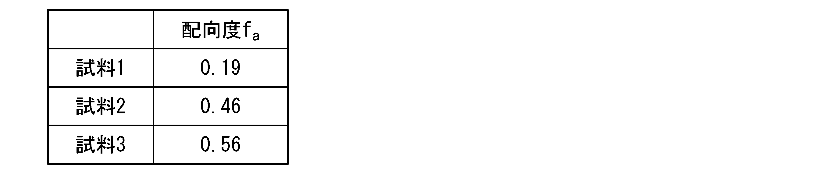
試料3において、炭素繊維が試料の繊維方向と平行に配向していることは既知である。試料1および試料2における炭素繊維の配向度faが試料3と同じく正であったことから、試料1および試料2において炭素繊維がMD方向に配向していることが確認された。
試料3においては、炭素繊維が完全に一方向に配向しているといってもよい。それにも拘わらず試料3の配向度faが1ではなく0.56となった理由は、よく知られているように、炭素繊維中におけるグラファイトの配向が完全ではないことによる。試料1および試料2における配向度faを評価するにあたっては、このことを考慮する必要がある。
試料3における配向度0.56を100%としたとき、試料1における配向度0.19は34%、試料2における配向度4.6は82%であり、どちらも十分に高いことが分かる。
試料3における配向度0.56を100%としたとき、試料1における配向度0.19は34%、試料2における配向度4.6は82%であり、どちらも十分に高いことが分かる。
以上、本発明を具体的な実施形態に即して説明したが、各実施形態は例として提示されたものであり、本発明の範囲を限定するものではない。本明細書に記載された各実施形態は、発明の効果が奏される範囲内で、様々に変形することができ、かつ、実施可能な範囲内で、他の実施形態により説明された特徴と組み合わせることができる。
1 繊維ウェブ形成装置
2 乾燥機
10 脱水流路
10A 上流端
10B 下流端
12 底面
14 側壁
16 吸引ボックス
17 垂直整流板
18 天井板
19 水平整流板
20 抄紙網
30 リザーバー
40 導入路
2 乾燥機
10 脱水流路
10A 上流端
10B 下流端
12 底面
14 側壁
16 吸引ボックス
17 垂直整流板
18 天井板
19 水平整流板
20 抄紙網
30 リザーバー
40 導入路
Claims (63)
- 繊維が特定方向に配向した繊維ウェブである配向繊維ウェブの製造方法であって、(i)抄紙網の表面である底面と、互いに平行な2つの側壁とからなり、上流端および下流端を有する脱水流路を準備すること、および、(ii)前記抄紙網を前記上流端から前記下流端に向かう方向に走行させながら、水を分散媒とする繊維分散液を前記上流端から前記脱水流路内に導入することを含み、前記脱水流路の前記底面は前記上流端から前記下流端に向かう方向に上り勾配を有し、前記脱水流路で前記繊維分散液が前記上流端から前記下流端に向かう方向に流れながら脱水されることにより繊維ウェブが形成される、製造方法。
- 前記上り勾配が5°以上、10°以上、15°以上、20°以上、または25°以上である、請求項1に記載の製造方法。
- 前記上り勾配が45°以下、40°以下、または35°以下である、請求項2に記載の製造方法。
- 前記脱水流路の上流端における水深Dと前記脱水流路の流路幅Wの比率D/Wが2以上、3以上、5以上、10以上、15以上、20以上、または30以上である、請求項1~3のいずれかに記載の製造方法。
- 前記脱水流路内に整流板を設置する、請求項1~3のいずれかに記載の製造方法。
- 前記整流板は、上流側の末端の角が丸められている、請求項5に記載の製造方法。
- 前記整流板が垂直整流板である、請求項5または6に記載の製造方法。
- 前記垂直整流板の下端にテーパーが付けられている、請求項7に記載の製造方法。
- 前記垂直整流板の下端と前記脱水流路の底面の間の隙間が20mm以下、10mm以下、5mm以下、または3mm以下である、請求項7または8に記載の製造方法。
- 複数の前記垂直整流板を前記脱水流路内に設置するものであり、その複数の前記垂直整流板の厚さが互いに同じであり、かつ、その複数の前記垂直整流板のうち任意の隣接する2枚の間隔、および、前記側壁とそれに最も近い前記垂直整流板の間隔が、いずれも前記垂直整流板の厚さと同等以上、2倍以上、または3倍以上である、請求項7~9のいずれかに記載の製造方法。
- 複数の前記垂直整流板を前記脱水流路内に設置するものであり、その複数の前記垂直整流板のうち任意の隣接する2枚の間隔、および、前記側壁とそれに最も近い前記垂直整流板の間隔が、いずれも、4cm以下、3cm以下、2cm以下、または1cm以下である、請求項7~10のいずれかに記載の製造方法。
- 前記整流板が水平整流板である、請求項5または6に記載の製造方法。
- 前記水平整流板の下流側の末端にテーパーが付けられている、請求項12に記載の製造方法。
- 前記水平整流板の下流側の末端と前記脱水流路の底面の間の隙間が20mm以下、10mm以下、5mm以下、または3mm以下である、請求項12または13に記載の製造方法。
- 複数の前記水平整流板を前記脱水流路内に設置するものであり、その複数の前記水平整流板の厚さが互いに同じであり、かつ、その複数の前記水平整流板のうち任意の隣接する2枚の間隔が前記水平整流板の厚さと同等以上、2倍以上、または3倍以上である、請求項12~14のいずれかに記載の製造方法。
- 複数の前記水平整流板を前記脱水流路内に設置するものであり、その複数の前記水平整流板のうち任意の隣接する2枚の間隔が、4cm以下、3cm以下、2cm以下、または1cm以下である、請求項12~15のいずれかに記載の製造方法。
- 前記脱水流路に天井板を設置する、請求項1~16のいずれかに記載の製造方法。
- 前記脱水流路が閉水路となるように前記繊維分散液の水位が設定される、請求項17に記載の製造方法。
- 前記底面と隣接する部分において前記側壁の内面が内側に湾曲している、請求項1~18のいずれかに記載の製造方法。
- 前記脱水流路における前記抄紙網の走行速度が、前記脱水流路の上流端における前記繊維分散液の平均流速の0.8~2.2倍である、請求項1~19のいずれかに記載の製造方法。
- 前記脱水流路の前記上流端に導入路が結合され、前記導入路を通して前記脱水流路に前記繊維分散液が供給される、請求項1~20のいずれかに記載の製造方法。
- 前記脱水流路と前記導入路との境界に隣接する部分における前記脱水流路の水平幅および深さが、それぞれ、前記境界に隣接する部分における前記導入路のそれの0.9~1.1倍である、請求項21に記載の製造方法。
- 前記導入路内において前記繊維分散液中の繊維が流れ方向に配向する、請求項21または22に記載の製造方法。
- 前記繊維分散液が含む繊維の繊維長が100mm以下である、請求項1~23のいずれかに記載の製造方法。
- 前記繊維が、繊維長3mm以上の成分を含む、請求項24に記載の製造方法。
- 前記繊維の95wt%以上が繊維長を12~50mmの範囲内に有する、請求項24に記載の製造方法。
- 前記繊維が、炭素繊維、無機繊維、金属繊維およびアラミド繊維から選ばれる1種以上の繊維を含む、請求項24~26のいずれかに記載の製造方法。
- 前記繊維が炭素繊維を含み、かつ、前記繊維分散液がポリアクリルアミドを含む、請求項27に記載の製造方法。
- 前記繊維分散液が粘剤を含み、更に、必要に応じて界面活性剤を含む、請求項1~27のいずれかに記載の製造方法。
- 前記繊維が更に熱可塑性樹脂繊維を含む、請求項27または28に係る製造方法。
- 更に、前記繊維ウェブを乾燥させることを含む、請求項1~30のいずれかに記載の製造方法。
- 前記乾燥の前に、前記繊維ウェブを湿った状態のまま延伸させることを含む、請求項31に記載の製造方法。
- 前記乾燥の後に前記繊維ウェブを液体で再度湿らせたうえ、湿った状態のまま延伸させることと、前記延伸の後に前記繊維ウェブを再度乾燥させることと、を含む請求項31に記載の製造方法。
- 抄紙網の表面である底面と、互いに平行な2つの側壁とからなり、上流端および下流端を有する脱水流路を備え、前記抄紙網を前記上流端から前記下流端に向かう方向に走行させつつ、水を分散媒とする繊維分散液を前記上流端から前記脱水流路内に導入し、前記脱水流路内を前記上流端から前記下流端に向かう方向に流しながら脱水させることができ、前記脱水流路の前記底面は前記上流端から前記下流端に向かう方向に上り勾配を有している、繊維ウェブ形成装置。
- 前記上り勾配が5°以上、10°以上、15°以上、20°以上、または25°以上である、請求項34に記載の繊維ウェブ形成装置。
- 前記上り勾配が45°以下、40°以下、または35°以下である、請求項35に記載の繊維ウェブ形成装置。
- 前記脱水流路の上流端における水深Dと前記脱水流路の流路幅Wの比率D/Wが2以上、3以上、5以上、10以上、15以上、20以上、または30以上である、請求項34~36のいずれかに記載の繊維ウェブ形成装置。
- 前記脱水流路内に設置された整流板を有する、請求項34~36のいずれかに記載の繊維ウェブ形成装置。
- 前記整流板は、上流側の末端の角が丸められている、請求項38に記載の繊維ウェブ形成装置。
- 前記整流板が垂直整流板である、請求項38または39に記載の繊維ウェブ形成装置。
- 前記垂直整流板の下端にテーパーが付けられている、請求項40に記載の繊維ウェブ形成装置。
- 前記垂直整流板の下端と前記脱水流路の底面の間の隙間が20mm以下、10mm以下、5mm以下、または3mm以下である、請求項40または41に記載の繊維ウェブ形成装置。
- 複数の前記垂直整流板を有し、その複数の前記垂直整流板の厚さが互いに同じであり、その複数の前記垂直整流板のうち任意の隣接する2枚の間隔、および、前記側壁とそれに最も近い前記垂直整流板の間隔が、いずれも前記垂直整流板の厚さと同等以上、2倍以上、または3倍以上である、請求項40~42のいずれかに記載の繊維ウェブ形成装置。
- 複数の前記垂直整流板を有し、その複数の前記垂直整流板のうち任意の隣接する2枚の間隔、および、前記側壁とそれに最も近い前記垂直整流板の間隔が、いずれも、4cm以下、3cm以下、2cm以下、または1cm以下である、請求項40~43のいずれかに記載の繊維ウェブ形成装置。
- 前記整流板が水平整流板である、請求項38または39に記載の繊維ウェブ形成装置。
- 前記水平整流板の下流側の末端にテーパーが付けられている、請求項45に記載の繊維ウェブ形成装置。
- 前記水平整流板の下流側の末端と前記脱水流路の底面の間の隙間が20mm以下、10mm以下、5mm以下、または3mm以下である、請求項45または46に記載の繊維ウェブ形成装置。
- 複数の前記水平整流板を有し、その複数の前記水平整流板の厚さが互いに同じであり、その複数の前記水平整流板のうち任意の隣接する2枚の間隔が、前記水平整流板の厚さと同等以上、2倍以上、または3倍以上である、請求項45~47のいずれかに記載の繊維ウェブ形成装置。
- 複数の前記水平整流板を有し、その複数の前記水平整流板のうち任意の隣接する2枚の間隔が、4cm以下、3cm以下、2cm以下、または1cm以下である、請求項45~47のいずれかに記載の繊維ウェブ形成装置。
- 前記脱水流路に設置された天井板を有する、請求項34~49のいずれかに記載の繊維ウェブ形成装置。
- 前記底面と隣接する部分において前記側壁の内面が内側に湾曲している、請求項34~50のいずれかに記載の繊維ウェブ形成装置。
- 前記脱水流路の前記上流端に結合された導入路を更に有し、前記導入路を通して前記脱水流路に前記繊維分散液を供給するようにした、請求項34~51のいずれかに記載の繊維ウェブ形成装置。
- 前記脱水流路と前記導入路との境界に隣接する部分における前記脱水流路の水平幅および深さが、それぞれ、前記境界に隣接する部分における前記導入路のそれの0.9~1.1倍である、請求項52に記載の繊維ウェブ形成装置。
- 請求項34~53のいずれかに記載の繊維ウェブ形成装置と、前記繊維ウェブ形成装置で形成される繊維ウェブを乾燥させるための乾燥機と、を有する配向繊維ウェブ製造装置。
- 繊維が特定方向に配向した繊維ウェブである配向繊維ウェブの製造方法であって、湿式法で繊維ウェブを形成することと、前記繊維ウェブを乾燥させることと、前記乾燥の前に前記繊維ウェブを湿った状態のまま延伸させることとを含む製造方法。
- 繊維が特定方向に配向した繊維ウェブである配向繊維ウェブの製造方法であって、湿式法で繊維ウェブを形成することと、前記繊維ウェブを乾燥させることと、前記乾燥の後に繊維ウェブを液体で再度湿らせたうえ、湿った状態のまま延伸させることと、前記延伸の後に前記繊維ウェブを再度乾燥させることとを含む製造方法。
- 繊維が特定方向に配向した繊維ウェブである配向繊維ウェブの製造方法であって、乾燥した繊維ウェブを液体で湿らせたうえ、湿った状態のまま延伸させることと、前記延伸の後に前記繊維ウェブを乾燥させることとを含む製造方法。
- 前記配向繊維ウェブが含む繊維の繊維長が100mm以下である、請求項55~57のいずれかに記載の製造方法。
- 前記配向繊維ウェブが含む繊維が、繊維長3mm以上の成分を含む、請求項58に記載の製造方法。
- 前記配向繊維ウェブが含む繊維の95wt%以上が繊維長を12~50mmの範囲内に有する、請求項59に記載の製造方法。
- 前記配向繊維ウェブが、炭素繊維、無機繊維、金属繊維およびアラミド繊維から選ばれる1種以上の繊維を含む、請求項55~60のいずれかに記載の製造方法。
- 前記配向繊維ウェブが更に熱可塑性樹脂繊維を含む、請求項61に記載の製造方法。
- 請求項1~33および55~62のいずれかに記載の製造方法で配向繊維ウェブを製造することと、前記配向繊維ウェブを熱硬化性樹脂組成物または熱可塑性樹脂組成物で含浸させることと、を含むプリプレグの製造方法。
Priority Applications (1)
| Application Number | Priority Date | Filing Date | Title |
|---|---|---|---|
| JP2023523463A JP7533781B2 (ja) | 2021-05-25 | 2022-05-23 | 配向繊維ウェブの製造方法、繊維ウェブ形成装置および配向繊維ウェブ製造装置 |
Applications Claiming Priority (2)
| Application Number | Priority Date | Filing Date | Title |
|---|---|---|---|
| JP2021-087588 | 2021-05-25 | ||
| JP2021087588 | 2021-05-25 |
Publications (1)
| Publication Number | Publication Date |
|---|---|
| WO2022250010A1 true WO2022250010A1 (ja) | 2022-12-01 |
Family
ID=84228789
Family Applications (1)
| Application Number | Title | Priority Date | Filing Date |
|---|---|---|---|
| PCT/JP2022/021094 Ceased WO2022250010A1 (ja) | 2021-05-25 | 2022-05-23 | 配向繊維ウェブの製造方法、繊維ウェブ形成装置および配向繊維ウェブ製造装置 |
Country Status (2)
| Country | Link |
|---|---|
| JP (1) | JP7533781B2 (ja) |
| WO (1) | WO2022250010A1 (ja) |
Citations (6)
| Publication number | Priority date | Publication date | Assignee | Title |
|---|---|---|---|---|
| JPS5777360A (en) * | 1974-02-08 | 1982-05-14 | Rutorafuiru Supinfuriisu Gmbh | Production of extensible and elastic fleece |
| US6066235A (en) * | 1998-04-03 | 2000-05-23 | E. I. Du Pont De Nemours And Company | Wetlay process for manufacture of highly-oriented fibrous mats |
| US6488810B1 (en) * | 1999-07-28 | 2002-12-03 | Voith Sulzer Papiertechnik Patent Gmbh | Process and device for producing a fibrous material web |
| JP2015040358A (ja) * | 2013-08-22 | 2015-03-02 | 中越パルプ工業株式会社 | 配向性セルロースナノファイバーシートおよびその調整方法 |
| JP2016210960A (ja) * | 2015-04-28 | 2016-12-15 | 王子ホールディングス株式会社 | 繊維強化プラスチック成形体用シート |
| JP2022049541A (ja) * | 2020-09-16 | 2022-03-29 | 三菱ケミカル株式会社 | 炭素繊維シート製造方法、炭素繊維ウェブ製造装置および炭素繊維シート製造装置 |
Family Cites Families (4)
| Publication number | Priority date | Publication date | Assignee | Title |
|---|---|---|---|---|
| US8157965B2 (en) | 2007-12-03 | 2012-04-17 | Bs Co., Ltd. | Sheet forming machine |
| JP5841780B2 (ja) | 2011-09-07 | 2016-01-13 | 阿波製紙株式会社 | プリプレグの製造方法と繊維強化熱硬化性樹脂成型体の製造方法 |
| JP5799753B2 (ja) | 2011-10-31 | 2015-10-28 | 王子ホールディングス株式会社 | 微細繊維含有シートの製造方法 |
| JP6131974B2 (ja) | 2015-03-06 | 2017-05-24 | 王子ホールディングス株式会社 | 微細繊維含有シートの製造方法 |
-
2022
- 2022-05-23 WO PCT/JP2022/021094 patent/WO2022250010A1/ja not_active Ceased
- 2022-05-23 JP JP2023523463A patent/JP7533781B2/ja active Active
Patent Citations (6)
| Publication number | Priority date | Publication date | Assignee | Title |
|---|---|---|---|---|
| JPS5777360A (en) * | 1974-02-08 | 1982-05-14 | Rutorafuiru Supinfuriisu Gmbh | Production of extensible and elastic fleece |
| US6066235A (en) * | 1998-04-03 | 2000-05-23 | E. I. Du Pont De Nemours And Company | Wetlay process for manufacture of highly-oriented fibrous mats |
| US6488810B1 (en) * | 1999-07-28 | 2002-12-03 | Voith Sulzer Papiertechnik Patent Gmbh | Process and device for producing a fibrous material web |
| JP2015040358A (ja) * | 2013-08-22 | 2015-03-02 | 中越パルプ工業株式会社 | 配向性セルロースナノファイバーシートおよびその調整方法 |
| JP2016210960A (ja) * | 2015-04-28 | 2016-12-15 | 王子ホールディングス株式会社 | 繊維強化プラスチック成形体用シート |
| JP2022049541A (ja) * | 2020-09-16 | 2022-03-29 | 三菱ケミカル株式会社 | 炭素繊維シート製造方法、炭素繊維ウェブ製造装置および炭素繊維シート製造装置 |
Non-Patent Citations (1)
| Title |
|---|
| HOUSSINE SEHAQUI, NGESA EZEKIEL MUSHI, SEIRA MORIMUNE, MICHAELA SALAJKOVA, TAKASHI NISHINO, LARS A. BERGLUND: "Cellulose Nanofiber Orientation in Nanopaper and Nanocomposites by Cold Drawing", ACS APPLIED MATERIALS & INTERFACES, vol. 4, no. 2, 22 February 2012 (2012-02-22), pages 1043 - 1049, XP055202877, ISSN: 19448244, DOI: 10.1021/am2016766 * |
Also Published As
| Publication number | Publication date |
|---|---|
| JPWO2022250010A1 (ja) | 2022-12-01 |
| JP7533781B2 (ja) | 2024-08-14 |
Similar Documents
| Publication | Publication Date | Title |
|---|---|---|
| Lehmonen et al. | Potential of foam-laid forming technology in paper applications | |
| US6451167B1 (en) | Wetlay process for manufacture of highly-oriented fibrous mats | |
| US3837999A (en) | Method of controlling the orientation of fibers in a foam formed sheet | |
| US3922190A (en) | Vacuum drainage device having a plurality of stepped blades | |
| US8758559B2 (en) | Systems and methods for making fiber webs | |
| US8747618B2 (en) | Energy saving papermaking forming apparatus, system, and method for lowering consistency of fiber suspension | |
| SE442029B (sv) | Papperstillverkningsapparatur samt forfarande for bildning av en fuktig pappersbana | |
| KR100538184B1 (ko) | 장망식 성형부에서 제지원료의 난류를 발생시키는 장치 및 방법 | |
| KR100423180B1 (ko) | 제지기계용롤및블레이드트윈-와이어간극성형장치 | |
| JP7540259B2 (ja) | 炭素繊維シート製造方法、炭素繊維ウェブ製造装置および炭素繊維シート製造装置 | |
| US3357880A (en) | Apparatus for making fibrous webs | |
| Hou et al. | Aqueous foam forming of quartz paper | |
| JP7533781B2 (ja) | 配向繊維ウェブの製造方法、繊維ウェブ形成装置および配向繊維ウェブ製造装置 | |
| CN113668288A (zh) | 通过泡沫施加将物质层施加到移动纤维幅材的方法和系统 | |
| IE61059B1 (en) | Process for forming a sheet of material | |
| JP2022049541A5 (ja) | ||
| FI81145B (fi) | Inloppslaoda. | |
| JP6361364B2 (ja) | 繊維強化プラスチック成形体用基材抄造装置および繊維強化プラスチック成形体用基材抄造方法 | |
| US6562197B2 (en) | Drainage hydrofoil blade | |
| KR20260055425A (ko) | 경사 분할 라멜라를 갖는 폼 형성 시스템 | |
| JP2604681B2 (ja) | 形成装置 | |
| CN117604802B (zh) | 斜网成型器 | |
| US8133355B2 (en) | Method for use in the wet end of a paper machine, cardboard machine or an equivalent web forming machine | |
| US3629057A (en) | Curved foil above the fourdrinier wire | |
| WO1992001110A1 (en) | Turbulence roll for a web former |
Legal Events
| Date | Code | Title | Description |
|---|---|---|---|
| 121 | Ep: the epo has been informed by wipo that ep was designated in this application |
Ref document number: 22811280 Country of ref document: EP Kind code of ref document: A1 |
|
| ENP | Entry into the national phase |
Ref document number: 2023523463 Country of ref document: JP Kind code of ref document: A |
|
| NENP | Non-entry into the national phase |
Ref country code: DE |
|
| 122 | Ep: pct application non-entry in european phase |
Ref document number: 22811280 Country of ref document: EP Kind code of ref document: A1 |