WO2022249240A1 - 起動システム及び起動方法 - Google Patents
起動システム及び起動方法 Download PDFInfo
- Publication number
- WO2022249240A1 WO2022249240A1 PCT/JP2021/019613 JP2021019613W WO2022249240A1 WO 2022249240 A1 WO2022249240 A1 WO 2022249240A1 JP 2021019613 W JP2021019613 W JP 2021019613W WO 2022249240 A1 WO2022249240 A1 WO 2022249240A1
- Authority
- WO
- WIPO (PCT)
- Prior art keywords
- terminal
- ram
- computer terminal
- activation system
- terminals
- Prior art date
- Legal status (The legal status is an assumption and is not a legal conclusion. Google has not performed a legal analysis and makes no representation as to the accuracy of the status listed.)
- Ceased
Links
Images




Classifications
-
- G—PHYSICS
- G06—COMPUTING OR CALCULATING; COUNTING
- G06F—ELECTRIC DIGITAL DATA PROCESSING
- G06F15/00—Digital computers in general; Data processing equipment in general
-
- G—PHYSICS
- G06—COMPUTING OR CALCULATING; COUNTING
- G06F—ELECTRIC DIGITAL DATA PROCESSING
- G06F9/00—Arrangements for program control, e.g. control units
- G06F9/06—Arrangements for program control, e.g. control units using stored programs, i.e. using an internal store of processing equipment to receive or retain programs
- G06F9/44—Arrangements for executing specific programs
- G06F9/445—Program loading or initiating
Definitions
- the present disclosure relates to an activation system and an activation method.
- one computer terminal that manages one interface device takes over work by transmitting data for taking over to another computer terminal that manages another interface device.
- the takeover data is data that is used after the OS (Operating System) and applications are activated. For this reason, in order to take over the work, it is necessary to start the application and load the data for the handover by the application, so it will take time before the work can be started on the new computer terminal. I had a problem.
- the present disclosure has been made in view of the problems described above, and aims to provide a technology that can reduce the time until work can be started on the computer terminal to which the change is made.
- a startup system includes one or more first terminals that have a first RAM and that transmits RAM contents stored in the first RAM when transitioning to a sleep state before a shutdown state, and a second RAM. and a second terminal for restoring the operating state of the first terminal before the sleep state by storing the contents of the RAM in the second RAM.
- the first terminal transmits the RAM contents stored in the first RAM when transitioning to the sleep state prior to the shutdown state, and the second terminal stores the RAM contents in the second RAM. Restoring the operating state before the sleep state of the first terminal. As a result, it is possible to reduce the time until work can be started on the new computer terminal.
- FIG. 1 is a block diagram showing the configuration of an activation system according to Embodiment 1;
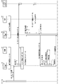
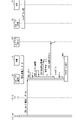
- FIG. 4 is a sequence diagram showing an example of the operation of the activation system according to Embodiment 1;
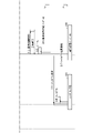
- FIG. 4 is a sequence diagram showing an example of the operation of the activation system according to Embodiment 1;
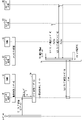
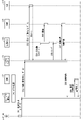
- FIG. 11 is a sequence diagram showing an example of the operation of the activation system according to Embodiment 2;
- FIG. 11 is a sequence diagram showing an example of the operation of the activation system according to Embodiment 2;
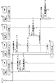
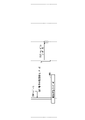
- FIG. 12 is a sequence diagram showing an example of the operation of the activation system according to the modified example of the second embodiment;
- FIG. 12 is a sequence diagram showing an example of the operation of the activation system according to Embodiment 3;
- FIG. 12 is a sequence diagram showing an example of the operation of the activation system according to Embodiment 3;
- FIG. 12 is a sequence diagram showing an example of the operation of the activation system according to Embodiment 4;
- FIG. 12 is a sequence diagram showing an example of the operation of the activation system according to Embodiment 4;
- FIG. 14 is a sequence diagram showing an example of the operation of the activation system according to Embodiment 5;
- FIG. 14 is a sequence diagram showing an example of the operation of the activation system according to Embodiment 5;
- FIG. 1 is a diagram showing the configuration of an activation system according to the first embodiment.
- the activation system of FIG. 1 includes computer terminals 10, 20, 30, and 40 provided at four seats of a vehicle, respectively, and a thin client server 110.
- Computer terminals 10 , 20 , 30 , 40 and thin client server 110 are communicatively connected via shared bus 100 .
- the computer terminal 10 includes a CPU (Central Processing Unit) 11, a RAM (Random Access Memory) 12, and an input/output device 13.
- the input/output device 13 is an interface device, and includes, for example, an input device such as a touch panel and an output device such as a display device.
- the CPU 11 executes programs such as applications, middleware, and OS based on operations received by the input/output device 13, stores the execution results in the RAM 12 as RAM contents, and stores the execution results in the input/output device 13 as appropriate. output. Note that in this specification, executing a program includes starting the program.
- the computer terminals 20, 30, 40 are provided with CPUs 21, 31, 41, RAMs 22, 32, 42, and input/output devices 23, 33, 43, respectively.
- CPUs 21, 31, 41, RAMs 22, 32, 42 and input/output devices 23, 33, 43 are the same as CPU 11, RAM 12 and input/output device 13, respectively.
- the operations of the CPU 11 and the like are sometimes referred to as the operations of the computer terminal 10 and the like.
- the computer terminal 10 which is the first terminal, transmits the RAM contents stored in the RAM 12, which is the first RAM, when transitioning to the sleep state before the shutdown state.
- the computer terminal 30, which is the first terminal transmits the RAM contents stored in the RAM 32, which is the first RAM, when transitioning to the sleep state before the shutdown state.
- the computer terminal 40 which is the first terminal, transmits the RAM contents stored in the RAM 42, which is the first RAM, when transitioning to the sleep state before the shutdown state. Note that the transition to the sleep state before the shutdown state referred to here may be while transitioning to the sleep state or while maintaining the sleep state.
- the computer terminal 20 which is the second terminal, stores the contents of the RAM transmitted from the computer terminals 10, 30, and 40 in the RAM 22, which is the second RAM. Restore the operating state of 30,40. For example, if the transmission and restoration are performed while the application is being executed on the computer terminal 10, the state in which the application was being executed on the computer terminal 10 is substantially restored on the computer terminal 20. . Note that in the following description, the computer terminal 20 performs the above restoration when the computer terminal 20 is started up, but the restoration is not limited to this.
- the first terminals are the computer terminals 10, 30, and 40
- the second terminal is the computer terminal 20, but the present invention is not limited to this.
- the number of first terminals may be one or more
- the number of second terminals may be one or more.
- the computer terminals 10, 30, and 40 may have the functions of the second terminal as well as the functions of the first terminal
- the computer terminal 20 may have the functions of the first terminal as well as the functions of the second terminal. may have
- the thin client server 110 includes a CPU 111, a RAM 112, and a HDD (Hard Disk Drive) 113.
- the CPU 111 controls the RAM 112 and the HDD 113 to store the contents transmitted from the computer terminals 10, 20, 30 and 40, and transmits the contents stored in the HDD 113 to the computer terminals 10, 20, 30 and 40. control.
- ⁇ Action> 2 and 3 are sequence diagrams showing an example of the operation of the activation system according to the first embodiment. Next, with reference to FIGS. 2 and 3, the operation when the terminal used by the user A is changed from the computer terminal 10 whose initial state is the operating state to the computer terminal 20 whose initial state is the shutdown state will be described. .
- step S1 user A performs a sleep operation on the computer terminal 10.
- step S2 the computer terminal 10 starts transitioning to the sleep state before the shutdown state.
- step S ⁇ b>3 the computer terminal 10 registers that the computer terminal 10 is in the sleep state for the user A in the thin client server 110 .
- computer terminals other than the computer terminal 10 can confirm that the computer terminal 10 is in the sleep state by accessing the thin client server 110 .
- step S4 the computer terminal 10 enters a sleep state.
- step S5 user A performs a startup operation on the computer terminal 20.
- the computer terminal 20 starts the process of confirming the terminal in the sleep state.
- step S7 the computer terminal 20 accesses the thin client server 110 and identifies a sleeping computer terminal registered in the thin client server 110 as a computer terminal whose operating state needs to be taken over.
- computer terminal 20 since computer terminal 10 is registered in thin client server 110 as being in a sleep state, computer terminal 20 identifies computer terminal 10 as a computer terminal that needs to take over the operating state.
- the computer terminal 20 requests the computer terminal 10 to transmit the RAM contents of the RAM 12 of the computer terminal 10.
- the computer terminal 10 activates the software in response to a request from the computer terminal 20, thereby entering a state in which the contents of RAM can be transmitted in the sleep state.
- the computer terminal 10 acquires the contents of RAM from the RAM 12.
- FIG. The contents of the RAM acquired here include sleep state information capable of restoring the operating state of the computer terminal 10 before the sleep state.
- computer terminal 10 transmits the contents of RAM acquired from RAM 12 to computer terminal 20 .
- the computer terminal 20 stores the contents of the RAM transmitted from the computer terminal 10 in the RAM 22 and develops them. As a result, the computer terminal 20 enters a sleep state in which the operating state before the sleep state of the computer terminal 10 can be restored. In step S13, the computer terminal 20 resumes to restore the operating state of the computer terminal 10 before the sleep state, thereby starting the transition from the sleep state to the operating state. In step S14, the computer terminal 20 registers with the thin client server 110 that the computer terminal 20 is in an operating state. At step S15, the computer terminal 20 requests the computer terminal 10 to shut down.
- step S ⁇ b>16 the computer terminal 10 starts transitioning to the shutdown state in response to a request from the computer terminal 20 .
- step S17 the computer terminal 10 registers with the thin client server 110 that the computer terminal 10 is in a shutdown state.
- the computer terminal 30 can be prevented from performing the processes of steps S6 to S8. In other words, only one computer terminal can take over the operating state of one computer terminal 10 .
- step S18 the computer terminal 10 is put into a shutdown state and the computer terminal 20 is put into an operating state.
- the computer terminal 10 transmits the contents of the RAM stored in the RAM 12 when transitioning to the sleep state before the shutdown state, and the computer terminal 20 Storing the RAM contents in RAM 22 restores the operating state of computer terminal 10 prior to the sleep state.
- the computer terminal of the change destination does not start programs such as applications, middleware, and OS, and load applications, it is possible to continue work on the computer terminal of the change destination. can. Therefore, it is possible to reduce the time until work can be started on the new computer terminal.
- the first embodiment can be applied to many existing OSs. can. Further, since the computer terminal 20 only needs to be activated when taking over the operating state from another computer terminal, and does not need to be activated all the time, improvements in convenience and economy can be expected.
- the computer terminal 10 directly transmits the contents of the RAM to the computer terminal 20 without going through another device such as the thin client server 110 .
- the computer terminal 10 directly transmits the contents of the RAM to the computer terminal 20 without going through another device such as the thin client server 110 .
- ⁇ Embodiment 2> 4 and 5 are sequence diagrams showing an example of the operation of the activation system according to the second embodiment.
- the same or similar components as those described above are given the same or similar reference numerals, and different components will be mainly described.
- the thin client server 110 is used in the operation of the activation system according to the first embodiment, but the thin client server 110 is unnecessary in the operation of the activation system according to the second embodiment.
- computer terminal 20 confirms with computer terminals 10, 30, and 40 the sleep states of computer terminals 10, 30, and 40 in order to correct the problem that thin client server 110 does not exist. Then, the computer terminal 20 identifies the computer terminal in the sleep state among the computer terminals 10, 30, and 40 as the computer terminal whose operating state should be restored.
- steps S1 and S2 After the processing of steps S1 and S2 is performed, the processing of steps S4 to S6 is performed without performing the processing of step S3, which is the registration processing to the thin client server 110.
- step S21 the computer terminal 20 confirms with the computer terminal 30 whether the computer terminal 30 is in the sleep state for the user A, and confirms that the computer terminal 30 is not in the sleep state in the example of FIG.
- step S22 the computer terminal 20 confirms with the computer terminal 40 whether the computer terminal 40 is in the sleep state for the user A, and confirms that the computer terminal 40 is not in the sleep state in the example of FIG.
- step S23 the computer terminal 20 confirms with the computer terminal 10 whether the computer terminal 10 is in the sleep state for the user A, and confirms that the computer terminal 10 is in the sleep state in the example of FIG. Then, the computer terminal 20 identifies the computer terminal 10 in the sleep state as a computer terminal that needs to take over the operating state.
- the computer terminal 20 comprehensively confirms the sleep states of the computer terminals 10, 30, and 40, thereby identifying the computer terminal whose operating state needs to be handed over. becomes possible.
- steps S8 to S18 is performed without performing steps S14 and S17.
- the order of processing for confirming the status of the computer terminals 10, 30, and 40 is not limited to the above, and the same applies to the following description.
- the computer terminal 20 restores the operating state by confirming the sleep state of the computer terminals 10, 30, and 40 with the computer terminals 10, 30, and 40. Identify the computer terminal that should According to such a configuration, it is possible to specify a computer terminal whose operating state needs to be handed over without using the thin client server 110 .
- FIG. 6 is a sequence diagram showing an example of the operation of the activation system according to the modification of the second embodiment.
- computer terminals 10, 20, 30 and 40 have HDDs 14, 24, 34 and 44, which are non-volatile memories, respectively. Then, when all of the computer terminals 10, 20, 30, 40 are shut down, the identification information identifying the computer terminal whose operating state is the last among the computer terminals 10, 20, 30, 40 is the HDD 14, 24, 34 , 44.
- step S31 user A performs a normal shutdown operation on the computer terminal 20.
- the computer terminal 20 acquires identification information identifying the computer terminal 20 that is in the last operating state among the computer terminals 10, 20, 30, and 40.
- FIG. in step S ⁇ b>33 computer terminal 20 stores the identification information in HDD 24 .
- step S34 the computer terminal 20 transmits the identification information to the computer terminal 10.
- step S35 the computer terminal 10 activates the software in response to the transmission from the computer terminal 20, so that the identification information can be stored in the HDD in the shutdown state.
- the shutdown state of this modified example is a state in which the software can be activated.
- step S ⁇ b>36 computer terminal 10 stores the transmitted identification information in HDD 14 .
- steps S37, S38, and S39 the same processing as steps S34, S35, and S36 is performed in the computer terminal 30, and the identification information is stored in the HDD34.
- steps S40, S41 and S42 processing similar to that of steps S34, S35 and S36 is performed in computer terminal 40, and the identification information is stored in HDD44.
- step S43 the computer terminal 20 enters a shutdown state.
- ⁇ Embodiment 3> 7 and 8 are sequence diagrams showing an example of the operation of the activation system according to the third embodiment.
- the same or similar components as those described above are given the same or similar reference numerals, and different components will be mainly described.
- the computer terminal 10 is configured to transmit the contents of RAM to the computer terminal 20 via the removable storage 120 .
- Removable storage 120 includes, for example, an optical disk, a USB (Universal Serial Bus) memory, and the like.
- step S51 user A performs a sleep operation on the computer terminal 10.
- the computer terminal 10 starts transitioning to the sleep state before the shutdown state.
- step S53 computer terminal 10 activates software for transmitting the contents of RAM in the sleep state.
- step S54 computer terminal 10 acquires the contents of RAM from RAM 12.
- FIG. in step S ⁇ b>55 computer terminal 10 stores the RAM contents obtained from RAM 12 in removable storage 120 .
- step S56 the computer terminal 10 automatically enters a shutdown state.
- step S57 user A replaces the removable storage 120 from the computer terminal 10 to the computer terminal 20.
- step S ⁇ b>58 the user B performs an activation operation on the computer terminal 10 .
- step S59 the computer terminal 10 becomes operational. Note that the processing of steps S58 and S59 may be performed at any point after the processing of step S57.
- step S60 user A performs a startup operation on the computer terminal 20.
- the computer terminal 20 confirms whether or not the removable storage 120 is attached.
- the computer terminal 20 acquires the RAM contents from the removable storage 120 in step S62.
- the computer terminal 20 stores the contents of the RAM in the RAM 22 and develops it.
- the computer terminal 20 enters a sleep state in which the operating state before the sleep state of the computer terminal 10 can be restored.
- the computer terminal 20 resumes to restore the operating state before the sleep state of the computer terminal 10, thereby starting the transition from the sleep state to the operating state.
- the computer terminal 20 becomes operational.
- computer terminal 10 transmits the contents of RAM to computer terminal 20 via removable storage 120 .
- Such a configuration eliminates the need for the software used in the first embodiment for transmitting the contents of the RAM in the sleep state.
- the computer terminal 10 can be put into a shutdown state before the computer terminal 20 is started, the state in which the user B other than the user A can use the computer terminal 10 can be brought forward. Also, the load on the communication network can be reduced.
- ⁇ Embodiment 4> 9 and 10 are sequence diagrams showing an example of the operation of the activation system according to the fourth embodiment.
- the same or similar components as those described above are given the same or similar reference numerals, and different components will be mainly described.
- the computer terminal 10 is configured to transmit the contents of RAM to the computer terminal 20 via the thin client server 110 .
- step S71 the processing of step S71 is performed.
- step S ⁇ b>71 the computer terminal 10 transmits the RAM content obtained from the RAM 12 to the thin client server 110 .
- step S ⁇ b>72 thin client server 110 stores the contents of RAM in HDD 113 .
- step S56 After the processing of step S56 is performed, the processing of steps S58 and S59 is performed without performing the processing of step S57. Note that the processing of steps S58 and S59 may be performed at any point after the processing of step S56.
- step S60 user A performs a startup operation on the computer terminal 20.
- the computer terminal 20 confirms with the thin client server 110 whether or not the contents of the RAM are stored.
- the computer terminal 20 requests the RAM contents from the thin client server 110 in step S74.
- step S ⁇ b>75 thin client server 110 acquires the contents of RAM from HDD 113 in response to a request from computer terminal 20 .
- step S ⁇ b>76 thin client server 110 transmits the read contents of RAM to computer terminal 20 . After that, the processing of steps S63 to S65 is performed.
- computer terminal 10 transmits the contents of RAM to computer terminal 20 via thin client server 110 .
- Such a configuration eliminates the need for the software used in the first embodiment for transmitting the contents of the RAM in the sleep state.
- the computer terminal 10 can be put into a shutdown state before the computer terminal 20 is started, the state in which the user B other than the user A can use the computer terminal 10 can be brought forward.
- the removable storage 120 is not used, security can be improved more than the third embodiment.
- ⁇ Embodiment 5> 11 and 12 are sequence diagrams showing an example of the operation of the activation system according to the fifth embodiment.
- the same or similar components as those described above are given the same or similar reference numerals, and different components will be mainly described.
- the ability of the thin client server 110 to execute the OS is higher than that of the computer terminal 10 to execute the OS.
- the thin client server 110 includes a virtual machine 115 that executes an OS when the computer terminal 10 is started up, and is configured to transmit RAM contents obtained by the execution to the computer terminal 10 .
- the operation between thin client server 110 and computer terminal 10 will be described. may be performed in between operations. Also, the configuration of the fifth embodiment may be implemented independently of the first to fourth embodiments.
- step S81 user A performs a startup operation on the computer terminal 10.
- step S82 the computer terminal 10 requests the contents of RAM capable of restoring the operating state in which the OS has been executed.
- step S83 the thin client server 110 acquires an OS image, which is information for executing the OS, from the HDD 113.
- step S84 the thin client server 110 causes the virtual machine 115 to execute (start) the OS based on the OS image.
- step S ⁇ b>85 the virtual machine 115 stores and develops information on the operating state obtained by executing the OS in the RAM 112 .
- step S86 thin client server 110 puts virtual machine 115 into a sleep state.
- the RAM contents of the RAM 112 include sleep state information capable of restoring the operating state in which the OS was executed.
- step S ⁇ b>87 thin client server 110 acquires the contents of RAM from RAM 112 .
- step S ⁇ b>88 thin client server 110 transmits the contents of RAM acquired from RAM 112 to computer terminal 10 .
- the computer terminal 10 stores the contents of the RAM transmitted from the thin client server 110 in the RAM 12 and develops them. As a result, the computer terminal 10 enters a sleep state in which the operating state in which the OS was executed can be restored. In step S90, the computer terminal 10 resumes to restore the operating state in which the OS was executed, thereby starting the transition from the sleep state to the operating state. In step S91, the computer terminal 10 notifies the thin client server 110 that the computer terminal 10 is in operation. In step S92, the thin client server 110 brings the virtual machine 115 into a shutdown state. At step S93, the computer terminal 10 becomes operational.
- the thin client server 110 executes the OS when the computer terminal 10 is started up, and transmits the contents of the RAM thus obtained to the computer terminal 10 . According to such a configuration, it is possible to shorten the apparent boot time of the computer terminal 10 by increasing the performance of the thin client server 110 . Also, the amount of data in the RAM content is generally smaller than that of the OS image, and the amount of data transmitted from the thin client server 110 to the computer terminal 10 is also small. Therefore, since the data transmission time can be shortened, the apparent boot time of the computer terminal 10 can be shortened.
Landscapes
- Engineering & Computer Science (AREA)
- Theoretical Computer Science (AREA)
- Software Systems (AREA)
- Physics & Mathematics (AREA)
- General Engineering & Computer Science (AREA)
- General Physics & Mathematics (AREA)
- Computer Hardware Design (AREA)
- Stored Programmes (AREA)
- Power Sources (AREA)
Abstract
変更先のコンピュータ端末で作業を開始可能になるまでの時間を低減可能な技術を提供することを目的とする。起動システムは、第1端末と第2端末とを備える。第1端末は、第1RAMを有し、かつ、シャットダウン状態前のスリープ状態に遷移する場合に第1RAMに記憶されているRAM内容を送信する。第2端末は、第2RAMを有し、かつ、RAM内容を第2RAMに記憶することによって第1端末のスリープ状態前の動作状態を復元する。
Description
本開示は、起動システム及び起動方法に関する。
近年、車両の複数の座席のそれぞれにインターフェース装置が設けられることによって、任意のユーザーが各インターフェース装置で個別にアプリケーションを実行することが可能なシステムが提案されている。このようなシステムにおいて、ユーザーが一の座席のインターフェース装置でアプリケーションを用いた作業を行っている場合に、別の座席に移動しても、当該別の座席のインターフェース装置で作業を継続可能にする技術が望まれている。そのような技術として、例えば特許文献1の技術やシンクライアントシステムの技術が提案されている。
従来技術では、一のインターフェース装置を管理する一のコンピュータ端末が、別のインターフェース装置を管理する別のコンピュータ端末に、引き継ぎ用のデータを送信することによって作業が引き継がれる。しかしながら、引き継ぎ用のデータは、OS(Operating System)及びアプリケーションを起動してから用いられるデータである。このため、作業の引き継ぎには、アプリケーションなどの起動、及び、アプリケーションによる引き継ぎ用のデータのロードなどが必要となることから、変更先のコンピュータ端末で作業を開始可能になるまでに時間がかかるという問題があった。
そこで、本開示は、上記のような問題点に鑑みてなされたものであり、変更先のコンピュータ端末で作業を開始可能になるまでの時間を低減可能な技術を提供することを目的とする。
本開示に係る起動システムは、第1RAMを有し、シャットダウン状態前のスリープ状態に遷移する場合に第1RAMに記憶されているRAM内容を送信する1つ以上の第1端末と、第2RAMを有し、RAM内容を第2RAMに記憶することによって第1端末のスリープ状態前の動作状態を復元する第2端末とを備える。
本開示によれば、第1端末は、シャットダウン状態前のスリープ状態に遷移する場合に第1RAMに記憶されているRAM内容を送信し、第2端末は、RAM内容を第2RAMに記憶することによって第1端末のスリープ状態前の動作状態を復元する。これにより、変更先のコンピュータ端末で作業を開始可能になるまでの時間を低減することができる。
本開示の目的、特徴、局面及び利点は、以下の詳細な説明と添付図面とによって、より明白となる。
<実施の形態1>
図1は、本実施の形態1に係る起動システムの構成を示す図である。図1の起動システムは、車両の4つの座席にそれぞれ設けられたコンピュータ端末10,20,30,40と、シンクライアントサーバ110とを備える。コンピュータ端末10,20,30,40と、シンクライアントサーバ110とは、共有バス100を介して通信可能に接続されている。
図1は、本実施の形態1に係る起動システムの構成を示す図である。図1の起動システムは、車両の4つの座席にそれぞれ設けられたコンピュータ端末10,20,30,40と、シンクライアントサーバ110とを備える。コンピュータ端末10,20,30,40と、シンクライアントサーバ110とは、共有バス100を介して通信可能に接続されている。
コンピュータ端末10は、CPU(Central Processing Unit)11とRAM(Random Access Memory)12と入出力装置13とを備える。入出力装置13は、インターフェース装置であり、例えば、タッチパネルなどの入力装置と、表示装置などの出力装置とを含む。CPU11は、入出力装置13で受け付けた操作に基づいてアプリケーション、ミドルウェア及びOSなどのプログラムを実行し、その実行結果をRAM内容としてRAM12に適宜記憶したり、その実行結果を入出力装置13に適宜出力したりする。なお本明細書において、プログラムを実行することは、プログラムを起動することを含む。
コンピュータ端末20,30,40は、CPU21,31,41、RAM22,32,42及び入出力装置23,33,43をそれぞれ備える。CPU21,31,41、RAM22,32,42及び入出力装置23,33,43は、CPU11、RAM12及び入出力装置13とそれぞれ同様である。以下では便宜上、CPU11などの動作をコンピュータ端末10などの動作として記載することもある。
本実施の形態1では、第1端末であるコンピュータ端末10は、シャットダウン状態前のスリープ状態に遷移する場合に第1RAMであるRAM12に記憶されているRAM内容を送信する。同様に、第1端末であるコンピュータ端末30は、シャットダウン状態前のスリープ状態に遷移する場合に第1RAMであるRAM32に記憶されているRAM内容を送信する。第1端末であるコンピュータ端末40は、シャットダウン状態前のスリープ状態に遷移する場合に第1RAMであるRAM42に記憶されているRAM内容を送信する。なお、ここでいうシャットダウン状態前のスリープ状態に遷移する場合とは、スリープ状態に遷移している間であってもよいし、スリープ状態を維持している間であってもよい。
本実施の形態1では、第2端末であるコンピュータ端末20は、コンピュータ端末10,30,40から送信されたRAM内容を、第2RAMであるRAM22に記憶することによってスリープ状態前のコンピュータ端末10,30,40の動作状態を復元する。例えば、コンピュータ端末10でアプリケーションが実行されていている間に上記送信及び復元が行われた場合には、コンピュータ端末20において、コンピュータ端末10でアプリケーションが実行されていた状態が実質的に復元される。なお、以下の説明では、コンピュータ端末20は、コンピュータ端末20の立ち上げ時に上記復元を行うが、これに限ったものではない。
以上のように本実施の形態1では、第1端末はコンピュータ端末10,30,40であり、第2端末はコンピュータ端末20であるが、これに限ったものではない。例えば、第1端末の個数は1つ以上であればよく、第2端末の個数は1つ以上であればよい。また、コンピュータ端末10,30,40は、第1端末の機能だけでなく第2端末の機能を有してもよいし、コンピュータ端末20は、第2端末の機能だけでなく第1端末の機能を有してもよい。
シンクライアントサーバ110は、CPU111と、RAM112と、HDD(Hard Disk Drive)113とを備える。CPU111は、コンピュータ端末10,20,30,40から送信された内容などをRAM112及びHDD113に記憶する制御を行ったり、HDD113に記憶された内容などをコンピュータ端末10,20,30,40に送信する制御を行ったりする。
<動作>
図2及び図3は、本実施の形態1に係る起動システムの動作の一例を示すシーケンス図である。次に図2及び図3を用いて、ユーザーAが使用する端末を、初期状態が動作状態であるコンピュータ端末10から、初期状態がシャットダウン状態であるコンピュータ端末20に変更する場合の動作について説明する。
図2及び図3は、本実施の形態1に係る起動システムの動作の一例を示すシーケンス図である。次に図2及び図3を用いて、ユーザーAが使用する端末を、初期状態が動作状態であるコンピュータ端末10から、初期状態がシャットダウン状態であるコンピュータ端末20に変更する場合の動作について説明する。
まずステップS1にて、ユーザーAがコンピュータ端末10に対してスリープ操作を行う。ステップS2にて、コンピュータ端末10は、シャットダウン状態前のスリープ状態への遷移を開始する。ステップS3にて、コンピュータ端末10は、シンクライアントサーバ110に、コンピュータ端末10がユーザーAについてスリープ状態であることを登録する。これにより、コンピュータ端末10以外のコンピュータ端末は、シンクライアントサーバ110にアクセスすることにより、コンピュータ端末10がスリープ状態であることを確認することが可能となる。ステップS4にて、コンピュータ端末10はスリープ状態になる。
ステップS5にて、ユーザーAがコンピュータ端末20に対して起動操作を行う。ステップS6にて、コンピュータ端末20は、スリープ状態の端末を確認する処理を開始する。ステップS7にて、コンピュータ端末20は、シンクライアントサーバ110にアクセスして、シンクライアントサーバ110に登録されているスリープ状態のコンピュータ端末を、動作状態の引き継ぎが必要なコンピュータ端末として特定する。図2の例では、コンピュータ端末10がスリープ状態であることがシンクライアントサーバ110に登録されているため、コンピュータ端末20は、コンピュータ端末10を動作状態の引き継ぎが必要なコンピュータ端末として特定する。
ステップS8にて、コンピュータ端末20は、コンピュータ端末10のRAM12のRAM内容を送信するようにコンピュータ端末10に要求する。ステップS9にて、コンピュータ端末10は、コンピュータ端末20からの要求に応じてソフトウェアを起動することによって、スリープ状態でRAM内容を送信可能な状態になる。ステップS10にて、コンピュータ端末10は、RAM12からRAM内容を取得する。ここで取得されるRAM内容は、コンピュータ端末10のスリープ状態前の動作状態を復元可能なスリープ状態の情報を含む。ステップS11にて、コンピュータ端末10は、RAM12から取得されたRAM内容をコンピュータ端末20に送信する。
ステップS12にて、コンピュータ端末20は、コンピュータ端末10から送信されたRAM内容をRAM22に記憶して展開する。これにより、コンピュータ端末20は、コンピュータ端末10のスリープ状態前の動作状態を復元可能なスリープ状態になる。ステップS13にて、コンピュータ端末20は、コンピュータ端末10のスリープ状態前の動作状態を復元するレジュームを行うことにより、スリープ状態から動作状態への遷移を開始する。ステップS14にて、コンピュータ端末20は、シンクライアントサーバ110に、コンピュータ端末20が動作状態であることを登録する。ステップS15にて、コンピュータ端末20は、コンピュータ端末10にシャットダウンを要求する。
ステップS16にて、コンピュータ端末10は、コンピュータ端末20からの要求に応じてシャットダウン状態への遷移を開始する。ステップS17にて、コンピュータ端末10は、シンクライアントサーバ110に、コンピュータ端末10がシャットダウン状態であることを登録する。これにより、例えば、この登録直後にコンピュータ端末30に起動操作が行われても、コンピュータ端末30がステップS6~ステップS8の処理を行わないようにすることができる。つまり、一つのコンピュータ端末10の動作状態を引き継ぐコンピュータ端末を一つにすることができる。ステップS18にて、コンピュータ端末10はシャットダウン状態になり、コンピュータ端末20は動作状態になる。
<実施の形態1のまとめ>
以上のような本実施の形態1に係る起動システムによれば、コンピュータ端末10は、シャットダウン状態前のスリープ状態に遷移する場合にRAM12に記憶されているRAM内容を送信し、コンピュータ端末20は、RAM内容をRAM22に記憶することによってコンピュータ端末10のスリープ状態前の動作状態を復元する。このような構成によれば、変更先のコンピュータ端末が、アプリケーション、ミドルウェア及びOSなどのプログラムの起動、並びに、アプリケーションのロードなどを行わなくても、変更先のコンピュータ端末で作業を継続することができる。このため、変更先のコンピュータ端末で作業を開始可能になるまでの時間を低減することができる。
以上のような本実施の形態1に係る起動システムによれば、コンピュータ端末10は、シャットダウン状態前のスリープ状態に遷移する場合にRAM12に記憶されているRAM内容を送信し、コンピュータ端末20は、RAM内容をRAM22に記憶することによってコンピュータ端末10のスリープ状態前の動作状態を復元する。このような構成によれば、変更先のコンピュータ端末が、アプリケーション、ミドルウェア及びOSなどのプログラムの起動、並びに、アプリケーションのロードなどを行わなくても、変更先のコンピュータ端末で作業を継続することができる。このため、変更先のコンピュータ端末で作業を開始可能になるまでの時間を低減することができる。
また、多くの既存のOSは、RAM内に情報を維持したままスリープ状態になるSupend to RAM機能を有しているため、多くの既存のOSに対して本実施の形態1を適用することができる。また、コンピュータ端末20は、他のコンピュータ端末から動作状態を引き継ぐ場合に起動されればよく、常時起動される必要がないため、利便性及び経済性の向上が期待できる。
また本実施の形態1では、コンピュータ端末10は、シンクライアントサーバ110などの他の装置を介さずにコンピュータ端末20にRAM内容を直接送信する。これにより、変更先のコンピュータ端末で作業を開始可能になるまでの時間をさらに低減することができる。
<実施の形態2>
図4及び図5は、本実施の形態2に係る起動システムの動作の一例を示すシーケンス図である。本実施の形態2に係る構成要素のうち、上述の構成要素と同じまたは類似する構成要素については同じまたは類似する参照符号を付し、異なる構成要素について主に説明する。
図4及び図5は、本実施の形態2に係る起動システムの動作の一例を示すシーケンス図である。本実施の形態2に係る構成要素のうち、上述の構成要素と同じまたは類似する構成要素については同じまたは類似する参照符号を付し、異なる構成要素について主に説明する。
実施の形態1に係る起動システムの動作ではシンクライアントサーバ110が用いられたが、本実施の形態2に係る起動システムの動作では、シンクライアントサーバ110は不要となっている。シンクライアントサーバ110がない不具合を是正するために、本実施の形態2では、コンピュータ端末20は、コンピュータ端末10,30,40のスリープ状態をコンピュータ端末10,30,40に確認する。そして、コンピュータ端末20は、コンピュータ端末10,30,40のうちスリープ状態のコンピュータ端末を、動作状態を復元すべきコンピュータ端末として特定する。
以下、図4及び図5の動作のうち、図2及び図3の動作と異なる部分について主に説明する。
ステップS1,S2の処理が行われた後、シンクライアントサーバ110への登録処理であるステップS3の処理を行わずに、ステップS4~S6の処理が行われる。
その後、ステップS21にて、コンピュータ端末20は、コンピュータ端末30がユーザーAについてスリープ状態であるかをコンピュータ端末30に確認し、図4の例ではコンピュータ端末30が当該スリープ状態でないことを確認する。ステップS22にて、コンピュータ端末20は、コンピュータ端末40がユーザーAについてスリープ状態であるかをコンピュータ端末40に確認し、図4の例ではコンピュータ端末40が当該スリープ状態でないことを確認する。ステップS23にて、コンピュータ端末20は、コンピュータ端末10がユーザーAについてスリープ状態であるかをコンピュータ端末10に確認し、図4の例ではコンピュータ端末10が当該スリープ状態であることを確認する。そして、コンピュータ端末20は、スリープ状態のコンピュータ端末10を、動作状態の引き継ぎが必要なコンピュータ端末として特定する。
このように、シンクライアントサーバ110を用いなくても、コンピュータ端末20は、コンピュータ端末10,30,40のスリープ状態を網羅的に確認することにより、動作状態の引き継ぎが必要なコンピュータ端末を特定することが可能となる。
その後、ステップS14,S17を行わずに、ステップS8~S18の処理が行われる。なお、コンピュータ端末10,30,40に対して状態を確認する処理の順序は上記に限ったものではなく、このことは以下の説明においても同様である。
<実施の形態2のまとめ>
以上のような本実施の形態2に係る起動システムによれば、コンピュータ端末20は、コンピュータ端末10,30,40のスリープ状態をコンピュータ端末10,30,40に確認することによって、動作状態を復元すべきコンピュータ端末を特定する。このような構成によれば、シンクライアントサーバ110を用いなくても、動作状態の引き継ぎが必要なコンピュータ端末を特定することができる。
以上のような本実施の形態2に係る起動システムによれば、コンピュータ端末20は、コンピュータ端末10,30,40のスリープ状態をコンピュータ端末10,30,40に確認することによって、動作状態を復元すべきコンピュータ端末を特定する。このような構成によれば、シンクライアントサーバ110を用いなくても、動作状態の引き継ぎが必要なコンピュータ端末を特定することができる。
<変形例>
図6は、実施の形態2の変形例に係る起動システムの動作の一例を示すシーケンス図である。本変形例では、コンピュータ端末10,20,30,40は、不揮発性メモリであるHDD14,24,34,44をそれぞれ有している。そして、コンピュータ端末10,20,30,40の全てがシャットダウンする場合に、コンピュータ端末10,20,30,40のうち動作状態が最後であるコンピュータ端末を識別する識別情報が、HDD14,24,34,44に記憶されるように構成されている。
図6は、実施の形態2の変形例に係る起動システムの動作の一例を示すシーケンス図である。本変形例では、コンピュータ端末10,20,30,40は、不揮発性メモリであるHDD14,24,34,44をそれぞれ有している。そして、コンピュータ端末10,20,30,40の全てがシャットダウンする場合に、コンピュータ端末10,20,30,40のうち動作状態が最後であるコンピュータ端末を識別する識別情報が、HDD14,24,34,44に記憶されるように構成されている。
次に図6を用いて、コンピュータ端末10,30,40がシャットダウン状態である場合に、コンピュータ端末20が動作状態からシャットダウン状態になる動作について説明する。
まずステップS31にて、ユーザーAがコンピュータ端末20に対して通常のシャットダウン操作を行う。ステップS32にて、コンピュータ端末20は、コンピュータ端末10,20,30,40のうち動作状態が最後であるコンピュータ端末20を識別する識別情報を取得する。ステップS33にて、コンピュータ端末20は、識別情報をHDD24に記憶する。
ステップS34にて、コンピュータ端末20は、識別情報をコンピュータ端末10に送信する。ステップS35にて、コンピュータ端末10は、コンピュータ端末20からの送信に応じてソフトウェアを起動することによって、シャットダウン状態で識別情報をHDDに記憶可能な状態になる。なお、本変形例のシャットダウン状態は、当該ソフトウェアの起動が可能な状態となっている。ステップS36にて、コンピュータ端末10は、送信された識別情報をHDD14に記憶する。
ステップS37,S38,S39にて、ステップS34,S35,S36の処理と同様の処理がコンピュータ端末30において行われ、識別情報がHDD34に記憶される。ステップS40,S41,S42にて、ステップS34,S35,S36の処理と同様の処理がコンピュータ端末40において行われ、識別情報がHDD44に記憶される。
ステップS43にて、コンピュータ端末20はシャットダウン状態になる。
以上のような本変形例に係る起動システムによれば、コンピュータ端末10,20,30,40のいずれを起動しても、識別情報に基づいて図5の動作と同様の動作を行うことにより、コンピュータ端末20のシャットダウン状態前の動作状態を復元することができる。なお、この場合のコンピュータ端末10,20,30,40の起動には、コールドブートが用いられてもよい。
<実施の形態3>
図7及び図8は、本実施の形態3に係る起動システムの動作の一例を示すシーケンス図である。本実施の形態3に係る構成要素のうち、上述の構成要素と同じまたは類似する構成要素については同じまたは類似する参照符号を付し、異なる構成要素について主に説明する。
図7及び図8は、本実施の形態3に係る起動システムの動作の一例を示すシーケンス図である。本実施の形態3に係る構成要素のうち、上述の構成要素と同じまたは類似する構成要素については同じまたは類似する参照符号を付し、異なる構成要素について主に説明する。
本実施の形態3では、コンピュータ端末10は、リムーバブルストレージ120を介してコンピュータ端末20にRAM内容を送信するように構成されている。リムーバブルストレージ120は、例えば、光学ディスク、USB(Universal Serial Bus)メモリなどを含む。
次に図7及び図8を用いて、ユーザーAが使用する端末を、初期状態が動作状態であるコンピュータ端末10から、初期状態がシャットダウン状態であるコンピュータ端末20に変更する場合の動作について説明する。
まずステップS51にて、ユーザーAがコンピュータ端末10に対してスリープ操作を行う。ステップS52にて、コンピュータ端末10は、シャットダウン状態前のスリープ状態への遷移を開始する。ステップS53にて、コンピュータ端末10は、スリープ状態でRAM内容を送信するためのソフトウェアを起動する。ステップS54にて、コンピュータ端末10は、RAM12からRAM内容を取得する。ステップS55にて、コンピュータ端末10は、RAM12から取得されたRAM内容をリムーバブルストレージ120に記憶する。ステップS56にて、コンピュータ端末10は自動的にシャットダウン状態になる。
ステップS57にて、ユーザーAは、リムーバブルストレージ120をコンピュータ端末10からコンピュータ端末20に付け替える。ステップS58にて、ユーザーBがコンピュータ端末10に対して起動操作を行う。ステップS59にて、コンピュータ端末10は動作状態になる。なお、ステップS58,S59の処理は、ステップS57の処理の後であればどの時点で行われてもよい。
ステップS60にて、ユーザーAがコンピュータ端末20に対して起動操作を行う。ステップS61にて、コンピュータ端末20は、リムーバブルストレージ120が取り付けられているか否かを確認する。図8の例のようにコンピュータ端末20にリムーバブルストレージ120が取り付けられている場合、ステップS62にて、コンピュータ端末20は、リムーバブルストレージ120からRAM内容を取得する。ステップS63にて、コンピュータ端末20は、RAM内容をRAM22に記憶して展開する。これにより、コンピュータ端末20は、コンピュータ端末10のスリープ状態前の動作状態を復元可能なスリープ状態になる。ステップS64にて、コンピュータ端末20は、コンピュータ端末10のスリープ状態前の動作状態を復元するレジュームを行うことにより、スリープ状態から動作状態への遷移を開始する。ステップS65にて、コンピュータ端末20は動作状態になる。
<実施の形態3のまとめ>
以上のような本実施の形態3に係る起動システムによれば、コンピュータ端末10は、リムーバブルストレージ120を介してコンピュータ端末20にRAM内容を送信する。このような構成によれば、実施の形態1で用いられたスリープ状態でRAM内容を送信するためのソフトウェアが不要となる。また、コンピュータ端末20を起動する前にコンピュータ端末10をシャットダウン状態にすることができるので、ユーザーA以外のユーザーBがコンピュータ端末10を使用できる状態を早めることができる。また、通信ネットワークの負荷を軽減することができる。
以上のような本実施の形態3に係る起動システムによれば、コンピュータ端末10は、リムーバブルストレージ120を介してコンピュータ端末20にRAM内容を送信する。このような構成によれば、実施の形態1で用いられたスリープ状態でRAM内容を送信するためのソフトウェアが不要となる。また、コンピュータ端末20を起動する前にコンピュータ端末10をシャットダウン状態にすることができるので、ユーザーA以外のユーザーBがコンピュータ端末10を使用できる状態を早めることができる。また、通信ネットワークの負荷を軽減することができる。
<実施の形態4>
図9及び図10は、本実施の形態4に係る起動システムの動作の一例を示すシーケンス図である。本実施の形態4に係る構成要素のうち、上述の構成要素と同じまたは類似する構成要素については同じまたは類似する参照符号を付し、異なる構成要素について主に説明する。
図9及び図10は、本実施の形態4に係る起動システムの動作の一例を示すシーケンス図である。本実施の形態4に係る構成要素のうち、上述の構成要素と同じまたは類似する構成要素については同じまたは類似する参照符号を付し、異なる構成要素について主に説明する。
本実施の形態4では、コンピュータ端末10は、シンクライアントサーバ110を介してコンピュータ端末20にRAM内容を送信するように構成されている。
以下、図9及び図10の動作のうち、図7及び図8の動作と異なる部分について主に説明する。
ステップS51~S54の処理が行われた後、ステップS71の処理が行われる。ステップS71にて、コンピュータ端末10は、RAM12から取得されたRAM内容をシンクライアントサーバ110に送信する。ステップS72にて、シンクライアントサーバ110は、HDD113にRAM内容を記憶する。
ステップS56の処理が行われた後、ステップS57の処理は行われずに、ステップS58,S59の処理が行われる。なお、ステップS58,S59の処理は、ステップS56の処理の後であればどの時点で行われてもよい。
ステップS60にて、ユーザーAがコンピュータ端末20に対して起動操作を行う。ステップS73にて、コンピュータ端末20は、シンクライアントサーバ110に対してRAM内容が記憶されているか否かを確認する。図10の例のようにシンクライアントサーバ110にRAM内容が記憶されている場合、ステップS74にて、コンピュータ端末20は、シンクライアントサーバ110にRAM内容を要求する。ステップS75にて、シンクライアントサーバ110は、コンピュータ端末20からの要求に応じてHDD113からRAM内容を取得する。ステップS76にて、シンクライアントサーバ110は、読み出したRAM内容をコンピュータ端末20に送信する。その後、ステップS63~S65の処理が行われる。
<実施の形態4のまとめ>
以上のような本実施の形態4に係る起動システムによれば、コンピュータ端末10は、シンクライアントサーバ110を介してコンピュータ端末20にRAM内容を送信する。このような構成によれば、実施の形態1で用いられたスリープ状態でRAM内容を送信するためのソフトウェアが不要となる。また、コンピュータ端末20を起動する前にコンピュータ端末10をシャットダウン状態にすることができるので、ユーザーA以外のユーザーBがコンピュータ端末10を使用できる状態を早めることができる。また、リムーバブルストレージ120を用いないため、実施の形態3よりもセキュリティ性を高めることができる。
以上のような本実施の形態4に係る起動システムによれば、コンピュータ端末10は、シンクライアントサーバ110を介してコンピュータ端末20にRAM内容を送信する。このような構成によれば、実施の形態1で用いられたスリープ状態でRAM内容を送信するためのソフトウェアが不要となる。また、コンピュータ端末20を起動する前にコンピュータ端末10をシャットダウン状態にすることができるので、ユーザーA以外のユーザーBがコンピュータ端末10を使用できる状態を早めることができる。また、リムーバブルストレージ120を用いないため、実施の形態3よりもセキュリティ性を高めることができる。
<実施の形態5>
図11及び図12は、本実施の形態5に係る起動システムの動作の一例を示すシーケンス図である。本実施の形態5に係る構成要素のうち、上述の構成要素と同じまたは類似する構成要素については同じまたは類似する参照符号を付し、異なる構成要素について主に説明する。
図11及び図12は、本実施の形態5に係る起動システムの動作の一例を示すシーケンス図である。本実施の形態5に係る構成要素のうち、上述の構成要素と同じまたは類似する構成要素については同じまたは類似する参照符号を付し、異なる構成要素について主に説明する。
本実施の形態5では、シンクライアントサーバ110がOSを実行する能力は、コンピュータ端末10よりもOSを実行する能力が高い。そして、シンクライアントサーバ110は、コンピュータ端末10の立ち上げ時にOSを実行する仮想マシン115を備え、その実行によって得られたRAM内容をコンピュータ端末10に送信するように構成されている。
なお、本実施の形態5では、シンクライアントサーバ110とコンピュータ端末10との間の動作について説明するが、これと同様の動作が、シンクライアントサーバ110とコンピュータ端末20,30,40のいずれかとの間の動作において行われてもよい。また、本実施の形態5の構成は、実施の形態1~4と独立して実現されてもよい。
次に図11及び図12を用いて、コンピュータ端末10が立ち上がる動作、つまりシャットダウン状態から動作状態になる動作について説明する。
まずステップS81にて、ユーザーAがコンピュータ端末10に対して起動操作を行う。ステップS82にて、コンピュータ端末10は、OSが実行された動作状態を復元可能なRAM内容を要求する。
ステップS83にて、シンクライアントサーバ110は、HDD113からOSを実行するための情報であるOSイメージを取得する。ステップS84にて、シンクライアントサーバ110は、仮想マシン115にOSイメージに基づいてOSを実行(起動)させる。ステップS85にて、仮想マシン115は、OSを実行することによって得られた動作状態の情報をRAM112に記憶して展開する。ステップS86にて、シンクライアントサーバ110は、仮想マシン115をスリープ状態にする。これにより、RAM112のRAM内容は、OSが実行された動作状態を復元可能なスリープ状態の情報を含むことになる。ステップS87にて、シンクライアントサーバ110は、RAM112からRAM内容を取得する。ステップS88にて、シンクライアントサーバ110は、RAM112から取得されたRAM内容をコンピュータ端末10に送信する。
ステップS89にて、コンピュータ端末10は、シンクライアントサーバ110から送信されたRAM内容をRAM12に記憶して展開する。これにより、コンピュータ端末10は、OSが実行された動作状態を復元可能なスリープ状態になる。ステップS90にて、コンピュータ端末10は、OSが実行された動作状態を復元するレジュームを行うことにより、スリープ状態から動作状態への遷移を開始する。ステップS91にて、コンピュータ端末10は、シンクライアントサーバ110に、コンピュータ端末10が動作状態であることを通知する。ステップS92にて、シンクライアントサーバ110は、仮想マシン115をシャットダウン状態にする。ステップS93にて、コンピュータ端末10は動作状態になる。
<実施の形態5のまとめ>
以上のような本実施の形態5に係る起動システムによれば、シンクライアントサーバ110は、コンピュータ端末10の立ち上げ時にOSを実行し、それによって得られたRAM内容をコンピュータ端末10に送信する。このような構成によれば、シンクライアントサーバ110の性能を高級にすることで、コンピュータ端末10の見かけのブート時間を短縮することができる。また、一般的にOSイメージよりもRAM内容のデータ量は小さく、シンクライアントサーバ110からコンピュータ端末10に送信されるデータ量が小さくなる。このため、データ送信時間を短縮することができるので、コンピュータ端末10の見かけのブート時間を短縮することができる。
以上のような本実施の形態5に係る起動システムによれば、シンクライアントサーバ110は、コンピュータ端末10の立ち上げ時にOSを実行し、それによって得られたRAM内容をコンピュータ端末10に送信する。このような構成によれば、シンクライアントサーバ110の性能を高級にすることで、コンピュータ端末10の見かけのブート時間を短縮することができる。また、一般的にOSイメージよりもRAM内容のデータ量は小さく、シンクライアントサーバ110からコンピュータ端末10に送信されるデータ量が小さくなる。このため、データ送信時間を短縮することができるので、コンピュータ端末10の見かけのブート時間を短縮することができる。
なお、各実施の形態及び各変形例を自由に組み合わせたり、各実施の形態及び各変形例を適宜、変形、省略したりすることが可能である。
上記した説明は、すべての局面において、例示であって、限定的なものではない。例示されていない無数の変形例が、想定され得るものと解される。
10,20,30,40 コンピュータ端末、12,22,32,42 RAM、14,24,34,44 HDD、110 シンクライアントサーバ、120 リムーバブルストレージ。
Claims (8)
- 第1RAMを有し、シャットダウン状態前のスリープ状態に遷移する場合に前記第1RAMに記憶されているRAM内容を送信する1つ以上の第1端末と、
第2RAMを有し、前記RAM内容を前記第2RAMに記憶することによって前記第1端末のスリープ状態前の動作状態を復元する第2端末と
を備える、起動システム。 - 請求項1に記載の起動システムであって、
前記1つ以上の第1端末は複数の第1端末であり、
前記第2端末は、
前記複数の第1端末のスリープ状態を前記複数の第1端末に確認し、前記複数の第1端末のうちスリープ状態の第1端末を、前記動作状態を復元すべき第1端末として特定する、起動システム。 - 請求項1に記載の起動システムであって、
前記第1端末及び前記第2端末のそれぞれは、不揮発性メモリをさらに有し、
前記第1端末及び前記第2端末の全てがシャットダウンする場合に、前記第1端末及び前記第2端末のうち動作状態が最後である端末を識別する識別情報が、前記第1端末及び前記第2端末のそれぞれの前記不揮発性メモリに記憶される、起動システム。 - 請求項1に記載の起動システムであって、
前記第1端末は、前記第2端末に前記RAM内容を直接送信する、起動システム。 - 請求項1に記載の起動システムであって、
前記第1端末は、リムーバブルストレージを介して前記第2端末に前記RAM内容を送信する、起動システム。 - 請求項1に記載の起動システムであって、
前記第1端末は、シンクライアントサーバを介して前記第2端末に前記RAM内容を送信する、起動システム。 - 請求項1に記載の起動システムであって、
前記第1端末及び前記第2端末のいずれかの端末よりもOSを実行する能力が高く、前記いずれかの端末の立ち上げ時に前記OSを実行し、それによって得られたRAM内容を前記いずれかの端末に送信するシンクライアントサーバをさらに備える、起動システム。 - 第1RAMを有する1つ以上の第1端末が、シャットダウン状態前のスリープ状態に遷移する場合に前記第1RAMに記憶されているRAM内容を送信し、
第2RAMを有する第2端末が、前記RAM内容を前記第2RAMに記憶することによって前記第1端末のスリープ状態前の動作状態を復元する、起動方法。
Priority Applications (2)
| Application Number | Priority Date | Filing Date | Title |
|---|---|---|---|
| PCT/JP2021/019613 WO2022249240A1 (ja) | 2021-05-24 | 2021-05-24 | 起動システム及び起動方法 |
| JP2023523724A JP7558407B2 (ja) | 2021-05-24 | 2021-05-24 | 起動システム及び起動方法 |
Applications Claiming Priority (1)
| Application Number | Priority Date | Filing Date | Title |
|---|---|---|---|
| PCT/JP2021/019613 WO2022249240A1 (ja) | 2021-05-24 | 2021-05-24 | 起動システム及び起動方法 |
Publications (1)
| Publication Number | Publication Date |
|---|---|
| WO2022249240A1 true WO2022249240A1 (ja) | 2022-12-01 |
Family
ID=84229670
Family Applications (1)
| Application Number | Title | Priority Date | Filing Date |
|---|---|---|---|
| PCT/JP2021/019613 Ceased WO2022249240A1 (ja) | 2021-05-24 | 2021-05-24 | 起動システム及び起動方法 |
Country Status (2)
| Country | Link |
|---|---|
| JP (1) | JP7558407B2 (ja) |
| WO (1) | WO2022249240A1 (ja) |
Citations (8)
| Publication number | Priority date | Publication date | Assignee | Title |
|---|---|---|---|---|
| JP2003242106A (ja) * | 2002-02-14 | 2003-08-29 | Sony Communication Network Corp | 情報同期方法とこの方法を利用可能な情報同期装置および情報端末 |
| JP2004054633A (ja) * | 2002-07-19 | 2004-02-19 | Sony Communication Network Corp | 情報同期方法とこの方法を利用可能な情報同期装置および情報端末 |
| JP2008090434A (ja) * | 2006-09-29 | 2008-04-17 | Toshiba Corp | 情報処理装置、およびメール受信方法 |
| JP2009145931A (ja) * | 2007-12-11 | 2009-07-02 | Hitachi Ltd | 仮想計算機と物理計算機との間のマイグレーション方法及びその計算機システム |
| JP2013041351A (ja) * | 2011-08-12 | 2013-02-28 | Nakayo Telecommun Inc | シンクライアントシステムのプログラム実行方法、携帯端末、およびサーバ装置 |
| JP2013168110A (ja) * | 2012-02-17 | 2013-08-29 | Pioneer Electronic Corp | 再生システム、再生機器、再生制御方法およびプログラム |
| JP2014503861A (ja) * | 2010-10-13 | 2014-02-13 | グーグル・インク | 複数のデバイス間の連続的アプリケーション実行 |
| JP2014523316A (ja) * | 2011-06-29 | 2014-09-11 | アマゾン テクノロジーズ インク | データロッカーの同期化 |
-
2021
- 2021-05-24 JP JP2023523724A patent/JP7558407B2/ja active Active
- 2021-05-24 WO PCT/JP2021/019613 patent/WO2022249240A1/ja not_active Ceased
Patent Citations (8)
| Publication number | Priority date | Publication date | Assignee | Title |
|---|---|---|---|---|
| JP2003242106A (ja) * | 2002-02-14 | 2003-08-29 | Sony Communication Network Corp | 情報同期方法とこの方法を利用可能な情報同期装置および情報端末 |
| JP2004054633A (ja) * | 2002-07-19 | 2004-02-19 | Sony Communication Network Corp | 情報同期方法とこの方法を利用可能な情報同期装置および情報端末 |
| JP2008090434A (ja) * | 2006-09-29 | 2008-04-17 | Toshiba Corp | 情報処理装置、およびメール受信方法 |
| JP2009145931A (ja) * | 2007-12-11 | 2009-07-02 | Hitachi Ltd | 仮想計算機と物理計算機との間のマイグレーション方法及びその計算機システム |
| JP2014503861A (ja) * | 2010-10-13 | 2014-02-13 | グーグル・インク | 複数のデバイス間の連続的アプリケーション実行 |
| JP2014523316A (ja) * | 2011-06-29 | 2014-09-11 | アマゾン テクノロジーズ インク | データロッカーの同期化 |
| JP2013041351A (ja) * | 2011-08-12 | 2013-02-28 | Nakayo Telecommun Inc | シンクライアントシステムのプログラム実行方法、携帯端末、およびサーバ装置 |
| JP2013168110A (ja) * | 2012-02-17 | 2013-08-29 | Pioneer Electronic Corp | 再生システム、再生機器、再生制御方法およびプログラム |
Non-Patent Citations (1)
| Title |
|---|
| SUZAKI, KUNIYASU: "Checkpoint for Network Transferable Computer", IPSJ SIG TECHNICAL REPORT, vol. 2001, no. 78, 27 July 2001 (2001-07-27), pages 19 - 26, ISSN: 0919- 6072 * |
Also Published As
| Publication number | Publication date |
|---|---|
| JPWO2022249240A1 (ja) | 2022-12-01 |
| JP7558407B2 (ja) | 2024-09-30 |
Similar Documents
| Publication | Publication Date | Title |
|---|---|---|
| US6434696B1 (en) | Method for quickly booting a computer system | |
| CN110704161B (zh) | 虚拟机创建方法、装置及计算机设备 | |
| JP4205560B2 (ja) | ディスクレスネットワークブータブルコンピュータにおける不揮発性メモリキャッシュを用いた信頼性の改善 | |
| EP2851807A1 (en) | Method and system for supporting resource isolation under multi-core architecture | |
| US20080022032A1 (en) | Concurrent virtual machine snapshots and restore | |
| JP2016508647A5 (ja) | ||
| CN110457261B (zh) | 数据访问方法、装置及服务器 | |
| JP2009512020A (ja) | オペレーティングシステムの停止状態からの高速起動 | |
| JPH11242631A (ja) | コンピュータシステムおよび同システムにおけるデータ保存/復元方法 | |
| CN116450244A (zh) | 芯片启动方法、装置、计算机设备和存储介质 | |
| WO2026021237A1 (zh) | 设备驱动文件加载方法、共享系统、及设备、介质和产品 | |
| JP2001290665A (ja) | プロセッサシステム | |
| WO2022249240A1 (ja) | 起動システム及び起動方法 | |
| KR101888781B1 (ko) | 비휘발성 메모리를 이용하는 영속적 dram 스토리지 및 그 작동 방법 | |
| JPH1139143A (ja) | 演算装置、該装置の制御方法、前記装置の制御プログラムを記憶した記憶媒体、演算装置を利用した電子回路装置、該装置の制御方法、前記装置の制御プログラムを記憶した記憶媒体 | |
| WO2015184902A1 (zh) | 一种智能分屏的并发处理方法及相应的智能终端 | |
| CN107179941A (zh) | 装置和优先级排序处理方法 | |
| JP2022178635A (ja) | 情報処理システム、情報処理装置とその制御方法及びプログラム | |
| JP6405972B2 (ja) | 動作検証装置、動作検証方法及び動作検証プログラム | |
| JP2014085909A (ja) | 情報処理装置、起動方法およびプログラム | |
| JP2001051854A (ja) | 情報管理システム | |
| JP2004005113A (ja) | 複数の実計算機上で動作する仮想計算機システム及びその制御方法 | |
| WO2007049423A1 (ja) | コンピュータシステム、及びそれにおける基本プログラムの起動方法 | |
| KR100292155B1 (ko) | 작업환경전환이용이한디지탈컴퓨터시스템과그사용방법 | |
| JP4723913B2 (ja) | 新しいビデオbiosを動作させる方法 |
Legal Events
| Date | Code | Title | Description |
|---|---|---|---|
| 121 | Ep: the epo has been informed by wipo that ep was designated in this application |
Ref document number: 21942898 Country of ref document: EP Kind code of ref document: A1 |
|
| ENP | Entry into the national phase |
Ref document number: 2023523724 Country of ref document: JP Kind code of ref document: A |
|
| NENP | Non-entry into the national phase |
Ref country code: DE |
|
| 122 | Ep: pct application non-entry in european phase |
Ref document number: 21942898 Country of ref document: EP Kind code of ref document: A1 |