WO2022249223A1 - 結晶成長装置 - Google Patents
結晶成長装置 Download PDFInfo
- Publication number
- WO2022249223A1 WO2022249223A1 PCT/JP2021/019517 JP2021019517W WO2022249223A1 WO 2022249223 A1 WO2022249223 A1 WO 2022249223A1 JP 2021019517 W JP2021019517 W JP 2021019517W WO 2022249223 A1 WO2022249223 A1 WO 2022249223A1
- Authority
- WO
- WIPO (PCT)
- Prior art keywords
- crystal
- laser
- raw material
- melt
- end side
- Prior art date
- Legal status (The legal status is an assumption and is not a legal conclusion. Google has not performed a legal analysis and makes no representation as to the accuracy of the status listed.)
- Ceased
Links
Images



Classifications
-
- C—CHEMISTRY; METALLURGY
- C30—CRYSTAL GROWTH
- C30B—SINGLE-CRYSTAL GROWTH; UNIDIRECTIONAL SOLIDIFICATION OF EUTECTIC MATERIAL OR UNIDIRECTIONAL DEMIXING OF EUTECTOID MATERIAL; REFINING BY ZONE-MELTING OF MATERIAL; PRODUCTION OF A HOMOGENEOUS POLYCRYSTALLINE MATERIAL WITH DEFINED STRUCTURE; SINGLE CRYSTALS OR HOMOGENEOUS POLYCRYSTALLINE MATERIAL WITH DEFINED STRUCTURE; AFTER-TREATMENT OF SINGLE CRYSTALS OR A HOMOGENEOUS POLYCRYSTALLINE MATERIAL WITH DEFINED STRUCTURE; APPARATUS THEREFOR
- C30B13/00—Single-crystal growth by zone-melting; Refining by zone-melting
- C30B13/16—Heating of the molten zone
- C30B13/22—Heating of the molten zone by irradiation or electric discharge
- C30B13/24—Heating of the molten zone by irradiation or electric discharge using electromagnetic waves
-
- B—PERFORMING OPERATIONS; TRANSPORTING
- B23—MACHINE TOOLS; METAL-WORKING NOT OTHERWISE PROVIDED FOR
- B23K—SOLDERING OR UNSOLDERING; WELDING; CLADDING OR PLATING BY SOLDERING OR WELDING; CUTTING BY APPLYING HEAT LOCALLY, e.g. FLAME CUTTING; WORKING BY LASER BEAM
- B23K26/00—Working by laser beam, e.g. welding, cutting or boring
-
- C—CHEMISTRY; METALLURGY
- C30—CRYSTAL GROWTH
- C30B—SINGLE-CRYSTAL GROWTH; UNIDIRECTIONAL SOLIDIFICATION OF EUTECTIC MATERIAL OR UNIDIRECTIONAL DEMIXING OF EUTECTOID MATERIAL; REFINING BY ZONE-MELTING OF MATERIAL; PRODUCTION OF A HOMOGENEOUS POLYCRYSTALLINE MATERIAL WITH DEFINED STRUCTURE; SINGLE CRYSTALS OR HOMOGENEOUS POLYCRYSTALLINE MATERIAL WITH DEFINED STRUCTURE; AFTER-TREATMENT OF SINGLE CRYSTALS OR A HOMOGENEOUS POLYCRYSTALLINE MATERIAL WITH DEFINED STRUCTURE; APPARATUS THEREFOR
- C30B13/00—Single-crystal growth by zone-melting; Refining by zone-melting
- C30B13/32—Mechanisms for moving either the charge or the heater
Definitions
- the present invention relates to a crystal growth apparatus.
- composition of the target single crystal and the composition of the melt are different, so the composition distribution of the melt changes along the crystal growth direction. Therefore, depending on the temperature gradient at the solid-liquid interface, compositional supercooling, which is supercooling caused by changes in the compositional distribution, occurs, making it difficult to grow crystals having a desired composition.
- the present invention has been made to solve the above-described problems.
- the purpose is to allow the growth of crystals with
- the one end side of a raw material body made of a solid raw material with which the seed crystal is in contact is heated by a heating mechanism to melt, and the heated portion is directed toward the other end side of the raw material body.
- a laser mechanism is provided for irradiating and heating a portion where the raw material is melted near the boundary region between the portion where the body is melted and the crystal.
- a laser mechanism is provided to irradiate and heat a portion where the raw material is melted near the boundary region between the portion where the raw material is melted and the crystal. Even if the composition of the melt and the concentration of impurities in the melt change as the crystal grows, a crystal having a desired composition can be grown.
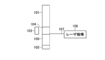
- FIG. 1A is a configuration diagram showing the configuration of a crystal growth apparatus according to Embodiment 1 of the present invention.
- FIG. 1B is a perspective view showing a partial configuration of the crystal growth apparatus according to Embodiment 1 of the present invention.
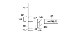
- FIG. 2A is a configuration diagram showing the configuration of a crystal growth apparatus according to Embodiment 2 of the present invention.
- FIG. 2B is a perspective view showing a partial configuration of a crystal growth apparatus according to Embodiment 2 of the present invention.
- FIG. 3A is a configuration diagram showing the configuration of a crystal growth apparatus according to Embodiment 3 of the present invention.
- 3B is a perspective view showing a partial configuration of a crystal growth apparatus according to Embodiment 3 of the present invention.
- a crystal growth apparatus according to an embodiment of the present invention will be described below.
- Embodiment 1 First, a crystal growth apparatus according to Embodiment 1 of the present invention will be described with reference to FIGS. 1A and 1B.
- This crystal growth apparatus is an apparatus for growing a raw material crystal 105 by heating and melting one end of a raw material body 101 made of a solid raw material, which is in contact with a seed crystal 102, with a heating mechanism 103. , further comprising a laser mechanism 106 .
- the raw material body 101 is, for example, rod-shaped.
- the heating mechanism 103 heats a desired portion by a heating method using, for example, induction heating, resistance heating, or a xenon lamp.
- the heating mechanism 103 is provided, for example, so as to surround the raw material body 101 .
- a plurality of laser mechanisms 106 can be arranged so as to surround the raw material body 101 . Also, the plurality of laser mechanisms 106 can be arranged so that the emitted laser light 107 passes over a first plane 151 perpendicular to the direction from one end side to the other end side of the raw material body 101 . In this case, it is desirable that each of the plurality of laser mechanisms 106 is arranged outside the optical path of the laser light 107 emitted from the other laser mechanisms 106 .
- Crystal growth can be carried out as follows by the floating zone melting method (floating zone method) or Bridgman method using this crystal growth apparatus.
- one end of the raw material body 101 with which the seed crystal 102 is in contact is heated and melted by the heating mechanism 103 to form the molten body 104, and the portion to be heated is directed toward the other end side of the raw material body 101.
- the location where the raw material 101 is melted (melted body 104) is moved from one end side to the other end side.
- the raw material crystal 105 is grown from the contact point of the seed crystal 102 toward the other end.
- the melt 104 in the vicinity of the boundary region between the melt 104 where the raw material 101 is melted and the crystal 105 is irradiated with the laser beam 107 emitted from the laser mechanism 106 to be heated.
- the temperature gradient from the melt 104 to the crystal 105 in the boundary region (interface) between the melt 104 and the crystal 105 is further increased by using the laser mechanism 106. can do.
- the laser mechanism 106 By using the laser mechanism 106, the temperature gradient in the boundary region between the crystal 105 and the melt 104 can be increased according to the composition distribution in the crystal growth direction.
- compositional supercooling occurs when the temperature gradient in the growth direction in the boundary region between the crystal 105 and the melt 104 is small. , the crystal growth progresses in a cell-like manner, and a single crystal of desired quality may not be obtained.
- the laser mechanism 106 irradiates the laser beam 107 to perform local heating, thereby further increasing the temperature gradient described above.
- a heating mechanism 103 using resistance heating is used to melt the raw material 101, and the seed crystal 102 is moved in a direction (one end side) opposite to the growth direction (the other end side) of the crystal 105 to heat the crystal 105. is grown, and the composition of the melt 104 changes along with this growth.
- the composition of the boundary region (interface) between the crystal 105 and the melt 104 differs from the composition of the boundary region between the raw material 101 and the melt 104, and a composition distribution occurs in the crystal growth direction.
- the differential value of this composition distribution in the boundary region between the crystal 105 and the melt 104 depends on the composition of the single crystal to be obtained and the composition of the raw material 101, and the concentration dependence of the liquidus line in the phase diagram of the raw material composition. change to reflect gender.
- the temperature gradient in the boundary region between the crystal 105 and the melt 104 can be increased to avoid compositional supercooling and grow a long crystal 105 .
- each of the plurality of laser mechanisms 106 is desirably arranged outside the optical path of the laser light 107 emitted from the other laser mechanism 106 .
- n virtual straight lines formed by the laser beams 107 emitted from each of the n laser mechanisms 106 two arbitrarily selected virtual straight lines do not form an angle of 180 degrees.
- a laser mechanism 106 is positioned.
- the energy conversion efficiency represented by Wout/Win is approximately 9%.
- the volume of the above device is approximately A 3 m 3 .
- the volume of the laser mechanism is approximately A 3 /25 m 3 , and it is expected that the volume of the device can be reduced to A 3 /8 m 3 . Therefore, when the heating mechanism is a laser mechanism and heating is performed only by the laser mechanism, the energy conversion efficiency can be increased and the volume of the device can be reduced as compared with a crystal growth device using a xenon lamp or resistance heating. For example, when heating is performed only by a laser mechanism, a high energy conversion efficiency of about 40% can be achieved compared to a crystal growth apparatus using the floating zone melting method, in which the heating mechanism is composed of a spheroidal mirror and a xenon lamp. , the volume of the device can be reduced to about 1/8.
- this crystal growth apparatus comprises one end of a raw material body 101 made of a solid raw material with which a seed crystal 102 is in contact.
- the apparatus is a device for crystal growth of a raw material crystal 105 by heating and melting the side of the apparatus with a heating mechanism 103 , and further includes a laser mechanism 106 .
- Embodiment 2 further includes a demultiplexing mechanism 108 for extracting a part of the laser beam 107 emitted from the laser mechanism 106 and irradiating the crystal 105 with it.
- the branching mechanism 108 includes, for example, a semireflector 108a and a reflector 108b.
- the laser beam 107 incident on the semi-reflecting mirror 108a is partially transmitted and partially reflected.
- the laser light reflected by the semi-reflecting mirror 108 a is reflected by the reflecting mirror 108 b to become the laser light 109 with which the crystal 105 is irradiated.
- the cooling rate of the crystal 105 is moderated, cracking of the crystal 105 is prevented, and a high-quality single crystal can be obtained.
- this crystal growth apparatus comprises one end of a raw material body 101 made of a solid raw material with which a seed crystal 102 is in contact. By heating and melting the side by the laser mechanism 106, the raw material crystal 105 is crystal-grown.
- the heating mechanism 103 is a laser mechanism 106 .
- each of the plurality of arranged laser mechanisms 106 is composed of a plurality of first laser mechanisms 106a and a plurality of second laser mechanisms 106b.
- the plurality of first laser mechanisms 106a pass the irradiated laser light 107a over a first plane 151 perpendicular to the direction from one end side to the other end side of the raw material body 101 .
- the plurality of second laser mechanisms 106 b causes the irradiated laser light 107 b to pass over a second plane 151 a with an angle different from that of the first plane 151 .
- the plurality of first laser mechanisms 106a form the melt 104, and the plurality of second laser mechanisms 106b further increase the temperature gradient from the melt 104 to the crystal 105 in the boundary region between the melt 104 and the crystal 105. do.
- Example 1 First, Example 1 will be described.
- crystal growth was performed by the floating zone melting method using the crystal growth apparatus according to the first embodiment.
- the heating mechanism 103 consisted of two spheroidal mirrors and two xenon lamps. Further, a plurality of laser mechanisms 106 are used, and the emitted laser light 107 is configured to pass over a first plane 151 perpendicular to the direction from one end side to the other end side of the raw material body 101 .
- a CW laser with an average output of 1 kW was used as each laser mechanism 106 .
- gadolinium pyrosilicate requires crystal growth from a non-stoichiometric melt (melt). Therefore, a raw material body 101 having a non-stoichiometric composition was prepared. This raw material body 101 is rod-shaped and has a constant composition regardless of location.
- the xenon lamp of the heating mechanism 103 is turned on, the light is collected by the spheroidal mirror, and the raw material 101 is melted to form the melt 104. After that, the raw material 101 and the crystal 105 are moved in the growth direction at a constant speed. , initiated crystal growth.
- the laser mechanism 106 is operated to irradiate the melt 104 with the laser beam 107 to increase the temperature of the melt 104 and increase the temperature gradient. to avoid compositional supercooling. As a result, a long crystal 105 could be grown.
- the temperature gradient at this time was 500° C./cm.
- Example 2 a crystal was grown by the Bridgman method using the crystal growth apparatus according to the second embodiment.
- the heating mechanism 103 is a resistance heating mechanism.
- a plurality of laser mechanisms 106 are used, and the emitted laser light 107 is configured to pass through a first plane 151 perpendicular to the direction from one end side to the other end side of the raw material body 101 .
- a CW laser with an average output of 1 kW was used as each laser mechanism 106 .
- the crystal 105 may be irradiated with the laser light 109 by using a laser mechanism similar to the laser mechanism 106 without using the branching mechanism 108 .
- a potassium tantalate niobate single crystal is grown using the above configuration.
- a raw material 101 of potassium tantalate niobate was melted by a heating mechanism 103 using resistance heating to form a melt 104, and crystal growth was started.
- Potassium tantalate niobate changes the composition of the melt 104 as the crystal 105 grows, and a composition distribution occurs along the growth direction of the crystal 105 . Therefore, when the length of the crystal 105 reaches 15 mm, the temperature gradient necessary for avoiding the compositional supercooling caused by the change in the compositional distribution cannot be realized by the heating by the heating mechanism 103, and the compositional Supercooling occurs.
- the laser beam 107 was emitted from the laser mechanism 106 to irradiate the melt 104 . This allowed the temperature of the melt 104 to rise and the required temperature gradient to be achieved.
- the crystal 105 was irradiated with a laser beam 109 . As a result, a long crystal 105 can be grown while avoiding compositional supercooling, and since the cooling rate is moderated by annealing, the occurrence of cracks is prevented, and a high-quality crystal 105 is obtained. was taken.
- Example 3 crystal growth was performed by the floating zone melting method using the crystal growth apparatus according to the third embodiment.
- the multiple first laser mechanisms 106 a are configured such that the emitted laser light 107 a passes over the first plane 151 .
- the plurality of second laser mechanisms 106b are configured such that the emitted laser light 107b passes over the second plane 151a.
- a CW laser with an average output of 1 kW was used as each laser mechanism.
- a single crystal of gadolinium pyrosilicate is grown using the above configuration.
- a gadolinium pyrosilicate single crystal should be grown from a non-stoichiometric melt 104 .
- a raw material body 101 having a non-stoichiometric composition was produced and melted by irradiation with a laser beam 107a to form a melt 104, and crystal growth was started.
- a laser mechanism for irradiating and heating a portion where the raw material is melted in the vicinity of the boundary region between the portion where the raw material is melted and the crystal. It is possible to further increase the temperature gradient in the boundary region between the part where the crystal is crystals can grow.
Landscapes
- Chemical & Material Sciences (AREA)
- Engineering & Computer Science (AREA)
- Crystallography & Structural Chemistry (AREA)
- Materials Engineering (AREA)
- Metallurgy (AREA)
- Organic Chemistry (AREA)
- Physics & Mathematics (AREA)
- Electromagnetism (AREA)
- Optics & Photonics (AREA)
- Plasma & Fusion (AREA)
- Mechanical Engineering (AREA)
- Crystals, And After-Treatments Of Crystals (AREA)
Abstract
Description
はじめに、本発明の実施の形態1に係る結晶成長装置について図1A、図1Bを参照して説明する。
次に、本発明の実施の形態2に係る結晶成長装置について、図2A、図2Bを参照してこの結晶成長装置は、固体の原料からなる原料体101の種結晶102が接触している一端側を、加熱機構103で加熱して溶融することにより、原料の結晶105を結晶成長させる装置であり、さらに、レーザ機構106を備える。これらの構成は、前述した実施の形態1と同様である。
次に、本発明の実施の形態3に係る結晶成長装置について、図3A、図3Bを参照してこの結晶成長装置は、固体の原料からなる原料体101の種結晶102が接触している一端側を、レーザ機構106で加熱して溶融することにより、原料の結晶105を結晶成長させる。実施の形態3では、加熱機構103は、レーザ機構106としている。
はじめに、実施例1について説明する。実施例1では、実施の形態1に係る結晶成長装置を用い、浮遊帯域溶融法で結晶成長をした。加熱機構103は、2台の回転楕円体ミラーと、2個とのキセノンランプとから構成した。また、複数のレーザ機構106を用い、出射されるレーザ光107が、原料体101の一端側から他端側の方向に垂直な第1平面151の上を通過する構成とした。各々のレーザ機構106として、平均出力が1kWのCWレーザを用いた。
次に、実施例2について説明する。実施例2では、実施の形態2に係る結晶成長装置を用い、ブリッジマン法で結晶成長をした。加熱機構103は、抵抗加熱による機構とした。また、複数のレーザ機構106を用い、出射されるレーザ光107が、原料体101の一端側から他端側の方向に垂直な第1平面151を通過する構成とした。各々のレーザ機構106として、平均出力が1kWのCWレーザを用いた。なお、分波機構108を用いることなく、レーザ機構106を同様のレーザ機構を用いて、結晶105にレーザ光109が照射される構成とすることもできる。
次に、実施例3について説明する。実施例3では、実施の形態3に係る結晶成長装置を用い、浮遊帯域溶融法で結晶成長をした。複数の第1レーザ機構106aは、出射されるレーザ光107aが、第1平面151の上を通過する構成とした。また、複数の第2レーザ機構106bは、出射されるレーザ光107bが、第2平面151aの上を通過する構成とした。また、各レーザ機構として、平均出力が1kWのCWレーザを用いた。
[参考文献2]IPGフォトニクス、「YLR-Uシリーズ、新型超コンパクト中出力1μmファイバーレーザー」、[令和3年5月12日検索]、(https://www.ipgphotonics.com/jp/products/lasers/mid-power-cw-fiber-lasers/1-micron/ylr-u-series)。
[参考文献3]S. Kawamura et al., "Phase Relations around the Pyrosilicate Phase in the Gd2O3-Ce2O3-SiO2 System", CRYSTAL GROWTH & DESIGN, vol. 9, no. 3, pp. 1470-1473, 2009.
Claims (5)
- 固体の原料からなる原料体の種結晶が接触している一端側を、加熱機構で加熱して溶融し、加熱する箇所を前記原料体の他端側の方向に移動させることで、前記原料体が溶融する箇所を前記一端側から前記他端側へ移動させ、前記種結晶が接触した箇所から前記他端側の方向に、前記原料の結晶を成長させる結晶成長装置であって、
前記原料体が溶融する箇所と前記結晶との境界領域の近傍の前記原料体が溶融する箇所にレーザ光を照射して加熱するレーザ機構を備えることを特徴とする結晶成長装置。 - 請求項1記載の結晶成長装置において、
前記レーザ機構は、前記原料体の周囲を囲う状態に複数配置されていることを特徴とする結晶成長装置。 - 請求項2記載の結晶成長装置において、
複数配置された前記レーザ機構の各々は、
照射されるレーザ光が前記原料体の前記一端側から前記他端側の方向に垂直な第1平面の上を通過する複数の第1レーザ機構と、
照射されるレーザ光が前記第1平面とは異なる角度の第2平面の上を通過する複数の第2レーザ機構と
を有することを特徴とする結晶成長装置。 - 請求項2または3記載の結晶成長装置において、
複数配置された前記レーザ機構の各々は、他の前記レーザ機構から出射されるレーザ光の光路上以外に配置されていることを特徴とする結晶成長装置。 - 請求項1~4のいずれか1項に記載の結晶成長装置において、
前記加熱機構は、前記レーザ機構であることを特徴とする結晶成長装置。
Priority Applications (3)
| Application Number | Priority Date | Filing Date | Title |
|---|---|---|---|
| PCT/JP2021/019517 WO2022249223A1 (ja) | 2021-05-24 | 2021-05-24 | 結晶成長装置 |
| US18/557,463 US20240263340A1 (en) | 2021-05-24 | 2021-05-24 | Method of growing crystal |
| JP2023523708A JPWO2022249223A1 (ja) | 2021-05-24 | 2021-05-24 |
Applications Claiming Priority (1)
| Application Number | Priority Date | Filing Date | Title |
|---|---|---|---|
| PCT/JP2021/019517 WO2022249223A1 (ja) | 2021-05-24 | 2021-05-24 | 結晶成長装置 |
Publications (1)
| Publication Number | Publication Date |
|---|---|
| WO2022249223A1 true WO2022249223A1 (ja) | 2022-12-01 |
Family
ID=84229658
Family Applications (1)
| Application Number | Title | Priority Date | Filing Date |
|---|---|---|---|
| PCT/JP2021/019517 Ceased WO2022249223A1 (ja) | 2021-05-24 | 2021-05-24 | 結晶成長装置 |
Country Status (3)
| Country | Link |
|---|---|
| US (1) | US20240263340A1 (ja) |
| JP (1) | JPWO2022249223A1 (ja) |
| WO (1) | WO2022249223A1 (ja) |
Citations (3)
| Publication number | Priority date | Publication date | Assignee | Title |
|---|---|---|---|---|
| JPS56160396A (en) * | 1980-05-09 | 1981-12-10 | Agency Of Ind Science & Technol | Zone melting method |
| JP2001257174A (ja) * | 2000-03-13 | 2001-09-21 | Sumitomo Heavy Ind Ltd | レーザアニール装置及びレーザアニール方法 |
| JP2019019046A (ja) * | 2017-07-12 | 2019-02-07 | 国立研究開発法人理化学研究所 | 単結晶育成装置 |
-
2021
- 2021-05-24 US US18/557,463 patent/US20240263340A1/en active Pending
- 2021-05-24 WO PCT/JP2021/019517 patent/WO2022249223A1/ja not_active Ceased
- 2021-05-24 JP JP2023523708A patent/JPWO2022249223A1/ja active Pending
Patent Citations (3)
| Publication number | Priority date | Publication date | Assignee | Title |
|---|---|---|---|---|
| JPS56160396A (en) * | 1980-05-09 | 1981-12-10 | Agency Of Ind Science & Technol | Zone melting method |
| JP2001257174A (ja) * | 2000-03-13 | 2001-09-21 | Sumitomo Heavy Ind Ltd | レーザアニール装置及びレーザアニール方法 |
| JP2019019046A (ja) * | 2017-07-12 | 2019-02-07 | 国立研究開発法人理化学研究所 | 単結晶育成装置 |
Also Published As
| Publication number | Publication date |
|---|---|
| US20240263340A1 (en) | 2024-08-08 |
| JPWO2022249223A1 (ja) | 2022-12-01 |
Similar Documents
| Publication | Publication Date | Title |
|---|---|---|
| US7519252B2 (en) | Laser annealing apparatus | |
| JP7554261B2 (ja) | マルチ波長調節可能半径方向モードファイバレーザ | |
| EP2186596B1 (en) | Laser working method and laser working apparatus | |
| US10556293B2 (en) | Laser machining device and laser machining method | |
| JP7392792B2 (ja) | 波長変換光デバイス | |
| EP2460614A1 (en) | Laser scribe processing method | |
| US5771117A (en) | Method and apparatus for nonlinear frequency generation using a strongly-driven local oscillator | |
| CN103038862B (zh) | 激光退火方法及其装置 | |
| WO2011086851A1 (ja) | 単結晶育成装置および単結晶育成方法 | |
| CN109465447A (zh) | 一种三激光辅助预热缓冷的增材制造方法及设备 | |
| JP3772933B2 (ja) | 3価のセリウムを含む磁性ガーネット単結晶の製造方法 | |
| KR20040020605A (ko) | 취성재료 절단용 레이저장치 및 이를 이용한 취성재료의절단방법 | |
| CN110336181B (zh) | 一种利用倍频系统实现会聚光束高效四倍频的方法 | |
| Huo et al. | The femtosecond laser fabrication of waveguide structures in transparent crystals | |
| US20240263340A1 (en) | Method of growing crystal | |
| JP4092414B2 (ja) | レーザアニール方法 | |
| JP2011161483A (ja) | レーザ加工装置 | |
| CN215698836U (zh) | 快速且提供较高加工品质的激光加工装置 | |
| EP3751339A1 (en) | Optical wavelength converter and method for manufacturing optical wavelength converter | |
| CN115609772A (zh) | 一种碳化硅晶片的剥离方法及其剥离装置 | |
| Lipatiev et al. | Space-selective crystallization of glass by an optical vortex beam | |
| JPS62160781A (ja) | レ−ザ光照射装置 | |
| US20230071407A1 (en) | Method for cutting a glass element and cutting system | |
| CN116441706A (zh) | 一种熔池搅拌方法及焊接装置 | |
| Lipat’ev et al. | Early stages of crystallization of lanthanum-borogermanate glass by a femtosecond laser beam |
Legal Events
| Date | Code | Title | Description |
|---|---|---|---|
| 121 | Ep: the epo has been informed by wipo that ep was designated in this application |
Ref document number: 21942881 Country of ref document: EP Kind code of ref document: A1 |
|
| WWE | Wipo information: entry into national phase |
Ref document number: 18557463 Country of ref document: US |
|
| WWE | Wipo information: entry into national phase |
Ref document number: 2023523708 Country of ref document: JP |
|
| NENP | Non-entry into the national phase |
Ref country code: DE |
|
| 122 | Ep: pct application non-entry in european phase |
Ref document number: 21942881 Country of ref document: EP Kind code of ref document: A1 |