WO2022244464A1 - Temperature calibration method - Google Patents
Temperature calibration method Download PDFInfo
- Publication number
- WO2022244464A1 WO2022244464A1 PCT/JP2022/013936 JP2022013936W WO2022244464A1 WO 2022244464 A1 WO2022244464 A1 WO 2022244464A1 JP 2022013936 W JP2022013936 W JP 2022013936W WO 2022244464 A1 WO2022244464 A1 WO 2022244464A1
- Authority
- WO
- WIPO (PCT)
- Prior art keywords
- temperature
- temperature calibration
- calibration method
- calibrated
- block
- Prior art date
Links
- 238000000034 method Methods 0.000 title claims abstract description 59
- 230000008569 process Effects 0.000 claims abstract description 11
- 230000007704 transition Effects 0.000 claims abstract description 11
- 238000003780 insertion Methods 0.000 claims description 23
- 230000037431 insertion Effects 0.000 claims description 23
- 238000009413 insulation Methods 0.000 claims description 19
- 230000002093 peripheral effect Effects 0.000 claims description 15
- 239000000463 material Substances 0.000 claims description 13
- 239000011810 insulating material Substances 0.000 claims description 11
- 230000005855 radiation Effects 0.000 claims description 8
- 238000003860 storage Methods 0.000 claims description 8
- 230000008859 change Effects 0.000 claims description 4
- 230000004308 accommodation Effects 0.000 abstract 1
- 229910052751 metal Inorganic materials 0.000 description 54
- 239000002184 metal Substances 0.000 description 54
- 239000010409 thin film Substances 0.000 description 18
- 239000000758 substrate Substances 0.000 description 8
- 238000009826 distribution Methods 0.000 description 6
- 238000012546 transfer Methods 0.000 description 5
- 238000012545 processing Methods 0.000 description 4
- 230000001681 protective effect Effects 0.000 description 4
- 239000004065 semiconductor Substances 0.000 description 4
- 238000010586 diagram Methods 0.000 description 3
- 229920005989 resin Polymers 0.000 description 3
- 239000011347 resin Substances 0.000 description 3
- IJGRMHOSHXDMSA-UHFFFAOYSA-N Atomic nitrogen Chemical compound N#N IJGRMHOSHXDMSA-UHFFFAOYSA-N 0.000 description 2
- MCMNRKCIXSYSNV-UHFFFAOYSA-N Zirconium dioxide Chemical compound O=[Zr]=O MCMNRKCIXSYSNV-UHFFFAOYSA-N 0.000 description 2
- 229910052782 aluminium Inorganic materials 0.000 description 2
- XAGFODPZIPBFFR-UHFFFAOYSA-N aluminium Chemical compound [Al] XAGFODPZIPBFFR-UHFFFAOYSA-N 0.000 description 2
- 238000011088 calibration curve Methods 0.000 description 2
- 230000008878 coupling Effects 0.000 description 2
- 238000010168 coupling process Methods 0.000 description 2
- 238000005859 coupling reaction Methods 0.000 description 2
- 239000000945 filler Substances 0.000 description 2
- 239000004519 grease Substances 0.000 description 2
- 238000010438 heat treatment Methods 0.000 description 2
- WABPQHHGFIMREM-UHFFFAOYSA-N lead(0) Chemical compound [Pb] WABPQHHGFIMREM-UHFFFAOYSA-N 0.000 description 2
- 239000007788 liquid Substances 0.000 description 2
- 238000004519 manufacturing process Methods 0.000 description 2
- 238000005259 measurement Methods 0.000 description 2
- 238000012986 modification Methods 0.000 description 2
- 230000004048 modification Effects 0.000 description 2
- BASFCYQUMIYNBI-UHFFFAOYSA-N platinum Chemical compound [Pt] BASFCYQUMIYNBI-UHFFFAOYSA-N 0.000 description 2
- 230000004043 responsiveness Effects 0.000 description 2
- 238000004544 sputter deposition Methods 0.000 description 2
- 229910000838 Al alloy Inorganic materials 0.000 description 1
- CURLTUGMZLYLDI-UHFFFAOYSA-N Carbon dioxide Chemical compound O=C=O CURLTUGMZLYLDI-UHFFFAOYSA-N 0.000 description 1
- RYGMFSIKBFXOCR-UHFFFAOYSA-N Copper Chemical compound [Cu] RYGMFSIKBFXOCR-UHFFFAOYSA-N 0.000 description 1
- 230000005679 Peltier effect Effects 0.000 description 1
- 238000010521 absorption reaction Methods 0.000 description 1
- 230000004075 alteration Effects 0.000 description 1
- PNEYBMLMFCGWSK-UHFFFAOYSA-N aluminium oxide Inorganic materials [O-2].[O-2].[O-2].[Al+3].[Al+3] PNEYBMLMFCGWSK-UHFFFAOYSA-N 0.000 description 1
- 238000009529 body temperature measurement Methods 0.000 description 1
- 239000005388 borosilicate glass Substances 0.000 description 1
- 235000011089 carbon dioxide Nutrition 0.000 description 1
- 239000000919 ceramic Substances 0.000 description 1
- 238000001816 cooling Methods 0.000 description 1
- 229910052802 copper Inorganic materials 0.000 description 1
- 239000010949 copper Substances 0.000 description 1
- PMHQVHHXPFUNSP-UHFFFAOYSA-M copper(1+);methylsulfanylmethane;bromide Chemical compound Br[Cu].CSC PMHQVHHXPFUNSP-UHFFFAOYSA-M 0.000 description 1
- 238000000151 deposition Methods 0.000 description 1
- 238000000605 extraction Methods 0.000 description 1
- 239000012467 final product Substances 0.000 description 1
- 239000007789 gas Substances 0.000 description 1
- 229910052732 germanium Inorganic materials 0.000 description 1
- GNPVGFCGXDBREM-UHFFFAOYSA-N germanium atom Chemical compound [Ge] GNPVGFCGXDBREM-UHFFFAOYSA-N 0.000 description 1
- 239000011521 glass Substances 0.000 description 1
- 230000017525 heat dissipation Effects 0.000 description 1
- 239000007769 metal material Substances 0.000 description 1
- 229910044991 metal oxide Inorganic materials 0.000 description 1
- 150000004706 metal oxides Chemical class 0.000 description 1
- 239000000203 mixture Substances 0.000 description 1
- 229910052757 nitrogen Inorganic materials 0.000 description 1
- 230000000149 penetrating effect Effects 0.000 description 1
- 229910052697 platinum Inorganic materials 0.000 description 1
- 229920001225 polyester resin Polymers 0.000 description 1
- 239000004645 polyester resin Substances 0.000 description 1
- 229920001296 polysiloxane Polymers 0.000 description 1
- 238000003908 quality control method Methods 0.000 description 1
- 239000003507 refrigerant Substances 0.000 description 1
- 230000035945 sensitivity Effects 0.000 description 1
- 229910052710 silicon Inorganic materials 0.000 description 1
- 239000010703 silicon Substances 0.000 description 1
- 229920002545 silicone oil Polymers 0.000 description 1
- 239000007787 solid Substances 0.000 description 1
- 239000010935 stainless steel Substances 0.000 description 1
- 229910001220 stainless steel Inorganic materials 0.000 description 1
- 238000006467 substitution reaction Methods 0.000 description 1
- 230000002195 synergetic effect Effects 0.000 description 1
- 238000003466 welding Methods 0.000 description 1
- 238000004804 winding Methods 0.000 description 1
Images


Classifications
-
- G—PHYSICS
- G01—MEASURING; TESTING
- G01K—MEASURING TEMPERATURE; MEASURING QUANTITY OF HEAT; THERMALLY-SENSITIVE ELEMENTS NOT OTHERWISE PROVIDED FOR
- G01K15/00—Testing or calibrating of thermometers
Definitions
- the present invention relates to a temperature calibration method using a temperature calibration device.
- thermometer calibration devices have been proposed that compare and calibrate temperatures using a reference thermometer and a thermometer to be calibrated as temperature sensors.
- This conventional temperature calibrating device calibrates the temperature of the thermometer to be calibrated by arranging the reference thermometer and the thermometer to be calibrated in a temperature calibration block that is kept at a constant temperature in a thermal equilibrium state.
- a liquefied gas, a refrigerator, an electric heater, or the like is used as a means for maintaining the temperature calibration block at a constant temperature, and the inside of the temperature calibration block is in a state of thermal equilibrium. generally takes a long time. Furthermore, since a constant temperature is maintained, the configuration of the device may become complicated. In addition, since it is difficult to maintain the temperature of the temperature calibration block at a constant and uniform temperature, temperature calibration accuracy is insufficient and temperature calibration is not performed efficiently.
- Embodiments of the present invention provide a temperature calibration method that can efficiently perform multi-point temperature calibration in a short time and can improve the calibration accuracy of the calibration temperature range by calibrating multiple temperature points. intended to provide
- the temperature calibration method according to the present embodiment is a temperature calibration method using a temperature calibration device having a temperature calibration block in which a reference temperature sensor and a temperature sensor to be calibrated are arranged.
- the temperature state in the transition process of is used as the calibration temperature.
- the embodiment of the present invention it is possible to provide a temperature calibration method capable of efficiently performing temperature calibration in a short time and improving the temperature calibration accuracy.
- FIG. 1 is a configuration diagram showing a temperature calibrating device according to an embodiment of the present invention;
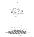
- FIG. The temperature sensor to be calibrated is shown, (a) is a perspective view, and (b) is a sectional view.
- 5 is a graph for explaining the concept of the temperature calibration method according to the embodiment of the present invention in comparison with the conventional one. It is a graph for explaining the concept of the same temperature calibration method. It is a flowchart which shows the same temperature calibration method. It is a graph which shows the temperature calibration data of the to-be-calibrated temperature sensor in the same temperature calibration method.
- 1 is a perspective view showing a temperature calibrating device according to an embodiment of the invention; FIG. It is an exploded perspective view of the temperature calibrating device.
- FIG. 1 is a configuration diagram showing a temperature calibration device
- FIG. 2 is a perspective view and cross-sectional view showing a temperature sensor to be calibrated
- FIGS. 3 and 4 are graphs for explaining the concept of the temperature calibration method.
- FIG. 5 is a flow chart showing the temperature calibration method
- FIG. 6 is a graph showing temperature calibration data of the temperature sensor to be calibrated.
- the scale of each part is appropriately changed so that each part has a recognizable size.
- the temperature calibration method of this embodiment is to compare and calibrate temperatures using a reference thermometer as a reference temperature sensor and a thermistor as a temperature sensor to be calibrated.
- the temperature calibrating device 10 includes a temperature calibrating block 2 and temperature control means 3.
- a control processing means 101 is also connected to the temperature calibrating device 10 .
- the temperature calibration block 2 is made of a material having high thermal conductivity and good thermal conductivity, and has a reference thermometer as a reference temperature sensor and a thermistor as a temperature sensor to be calibrated. This is the block where the thermometer and thermistor are placed.
- the temperature control means 3 is thermally coupled with the temperature calibration block 2 and controls the temperature of the temperature calibration block 2.
- a Peltier module for example, a Peltier module, a heater, or the like is used.
- the control processing means 101 has an input part and an output part, monitors and controls the temperature of the temperature calibration block 2, acquires data of the reference thermometer and thermistor, and controls the temperature calibration device 10 as a whole. control of
- the temperature sensor to be calibrated is a thin film thermistor T as shown in FIG.
- the thin film thermistor T includes an element substrate T11, a conductive layer T12 formed on the substrate T11 , a thin film element layer T13 , and a protective insulating layer T14 .
- the element substrate T11 has a substantially rectangular shape and is made of an insulating alumina material.
- the material for forming the substrate T11 ceramics such as aluminum nitride and zirconia, or semiconductor materials such as silicon and germanium may be used.
- the substrate T11 is extremely thin and formed to have a thickness of 50 ⁇ m to 150 ⁇ m, preferably 100 ⁇ m or less. By using such an ultra-thin substrate T11 for a thin film thermistor, it is possible to realize a thermosensitive element with reduced heat capacity, high sensitivity, and excellent thermal responsiveness.
- the conductive layer T12 constitutes a wiring pattern and is formed on the substrate T11.
- the conductive layer T12 is formed by depositing a metal thin film by a sputtering method.
- a pair of electrode portions T12a electrically connected to the conductive layer T12 are formed integrally with the conductive layer T12 on both ends of the substrate T11.
- the thin film element layer T13 is a thermistor composition and is composed of an oxide semiconductor having a negative temperature coefficient.
- the thin film element layer T13 is formed on the conductive layer T12 by sputtering or the like, and is electrically connected to the conductive layer T12 .
- the thin film element layer may be composed of an oxide semiconductor having a positive temperature coefficient.
- a protective insulating layer T14 is formed to cover the thin film element layer T13 and the conductive layer T12 .
- the protective insulating layer T14 is a protective glass layer made of borosilicate glass.
- a lead wire T12b made of metal is welded and electrically connected to the electrode portion T12a .
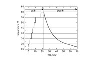
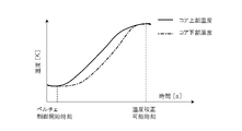
- the horizontal axis indicates time (h), and the vertical axis indicates the temperature (°C) of the temperature calibration block.
- the left side shows the conventional temperature calibration method, and the right side shows the temperature calibration method of this embodiment.
- the conventional temperature calibration method is a stationary comparison method that performs calibration in the thermal equilibrium state of the temperature calibration block.
- the temperature of the temperature calibration block is set to, for example, 30°C, 35°C, 40°C, etc., and calibration is performed after waiting until the set constant temperature state, that is, the thermal equilibrium state is reached. be. Therefore, in the steady-state comparison method, it takes about 20 hours when calibration is performed at 7 points from 30°C to 60°C every 5°C. Since multipoint calibration takes time, two to six point calibration is generally performed for general temperature calibration.
- the temperature calibration method of this embodiment is a non-stationary comparison method in which calibration is performed in the temperature state in the transition process of gradual temperature changes without the temperature calibration block reaching a thermal equilibrium state. Therefore, there is no need to wait until the temperature of the temperature calibration block reaches thermal equilibrium, and calibration can be performed in a short time by gradually controlling the temperature calibration block to different calibration temperatures.
- the figure shows a temperature curve of a gradual transition process of temperature change when the temperature calibration block is naturally cooled.
- the temperature curve in the figure which is the temperature state in the transition process of the gradual temperature change of the present invention, takes about 30 hours to cool from 60°C to 30°C, and changes by 1°C per hour. It is confirmed that the temperature sensor with a small thermal time constant to be calibrated can be regarded as a thermally stable state equivalent to the thermal equilibrium state although it is not in the thermal equilibrium state.
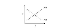
- the horizontal axis indicates time
- the vertical axis indicates the temperature (°C) of the temperature calibration block. It shows the transition process.
- calibration is performed using the temperature in the transition process in the case of temperature increase or temperature decrease as the calibration temperature. It is preferable that the temperature control means 3 control whether the temperature calibration block is raised or lowered.
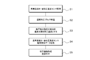
- a thin film thermistor T is placed as a reference thermometer and a temperature sensor to be calibrated in the placement part of the temperature calibration block 2 (S1).
- the temperature calibration block 2 is heated to a predetermined temperature by setting the temperature control means 3 (S2).
- the temperature calibration block 2 is heated to the set predetermined temperature.
- the temperature state in the transition process of gradual temperature rise before the temperature calibration block 2 reaches a predetermined temperature (thermal equilibrium state) is referred to as the calibration temperature.
- the calibration temperature can be calibrated by capturing a large number of temperature points (multiple points) (S3). This is because the thin film thermistor T has a small thermal time constant, excellent thermal responsiveness, and high resolution. That is, it is possible to calibrate at a large number of temperature points corresponding to the resolution.
- the relationship between the reference thermometer and the thin-film thermistor T of the temperature sensor to be calibrated that is, the data of the correlation between the temperature of the reference thermometer and the resistance value of the thin-film thermistor T is obtained (S4).
- a calibration curve for the resistance value of the thin-film thermistor T of the temperature sensor to be calibrated is created to calibrate the temperature (S5).
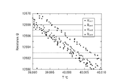
- FIG. 6 shows detailed data around 40° C. of the temperature calibration block (reference thermometer), where the horizontal axis indicates temperature (° C.) and the vertical axis indicates the resistance value ( ⁇ ) of the thin film thermistor T.
- the calibration data shows the results of four repeated measurements of the thin film thermistor T.
- the calibration data are from 39.99° C. to 40.01° C., showing that calibration at 40 temperature points is possible in this temperature range. It can be seen from the results of four repeated measurements that there is only a slight difference in each comparison.
- the temperature can be changed by 1° C. per hour under the control of the temperature control means 3.
- calibration at 4000 temperature points is possible. Therefore, a large number of temperature points can be captured and continuously calibrated, and the calibration accuracy can be remarkably improved.
- an electronic thermometer using a thermistor can be calibrated at 40,000 temperature points with a temperature range of 32°C to 42°C. As described above, according to the present embodiment, temperature calibration can be performed efficiently in a short time, and temperature calibration accuracy can be improved.
- thermoelectric thermistor as a temperature sensor to be calibrated to a customer
- temperature calibration data at a large number of temperature points for example, at least 20 temperature points
- the thermistor is provided as a thermistor with temperature calibration data.
- FIG. 7 and 8 are a perspective view and an exploded perspective view showing the temperature calibration device
- FIGS. 9 and 10 are a perspective view and an exploded perspective view showing the temperature calibration block and the Peltier module taken out
- FIG. 4 is an exploded perspective view showing a temperature calibration block
- FIG. 12 is a longitudinal sectional view and a top view showing the temperature calibrating device
- FIG. 13 is a transverse sectional view showing the temperature calibrating device.
- 14 is a front view and a top view showing the core of the temperature calibration block
- FIGS. 15 and 16 are a front view and a top view showing the Peltier holder
- FIG. 17 is a cross section schematically showing the heat insulating material. It is a diagram. Also, FIG. 18 is a graph showing the temperature distribution of the temperature calibration block. In each figure, illustration of wiring relationships such as lead wires is omitted. Also, the same or corresponding parts are denoted by the same reference numerals, and redundant description may be omitted.
- the temperature calibrating device of this embodiment compares and calibrate the temperature using a reference thermometer as a reference temperature sensor and a thermistor as a temperature sensor to be calibrated.
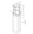
- the reference thermometer 5 uses a platinum resistance thermometer calibrated according to the method defined by the International Temperature Scale (see FIG. 12).
- the thermistor is, for example, a thin film thermistor.
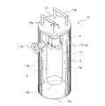
- the temperature calibration device 10 comprises a vacuum insulation container 1, a temperature calibration block 2 housed in the vacuum insulation container 1, and a Peltier module 3 as temperature control means.
- the temperature calibration device 10 has a substantially cylindrical shape with a diameter of ⁇ 150 mm and a height of about 360 mm.
- the vacuum insulation container 1 constitutes the appearance of the temperature calibrating device 10, is formed in a substantially cylindrical shape from a thin stainless steel material, and has an outer cylindrical portion 11 and an inner cylindrical portion 12.
- the outer cylindrical portion 11 is composed of an outer peripheral side wall 11a, a circular bottom wall 11b forming the bottom surface of the outer peripheral side wall 11a, and a ring-shaped upper wall 11c forming the upper surface of the outer peripheral side wall 11a.
- the inner cylindrical portion 12 has a cylindrical shape with a bottom, and is composed of an outer peripheral side wall 12a and a circular bottom wall 12b forming the bottom surface of the outer peripheral side wall 12a, and a circular opening 12c is formed at the top. .
- the edge of the opening 12c of the inner cylindrical portion 12 is joined to the ring-shaped upper wall 11c of the outer cylindrical portion 11 by welding or the like.
- the outer cylindrical portion 11 and the inner cylindrical portion 12 form a closed spatial region, that is, a vacuum region Va on the outer peripheral side of the inner cylindrical portion 12 .
- a vacuum flange 11d is formed on the upper side of the outer cylindrical portion 11 as a connection port to which a vacuum pump is connected. By connecting a vacuum pump to the vacuum flange 11d and operating the vacuum pump, the vacuum area Va can be evacuated.
- a heat insulating material which will be described later, is arranged in the vacuum area Va.
- a temperature calibration block 2 and a Peltier module 3 thermally coupled to the temperature calibration block 2 are inserted into the inner cylindrical portion 12 in a connected state. Specifically, the member 230 connecting the temperature calibration block 2 and the Peltier module 3 is inserted from the opening 12c of the inner cylindrical portion 12 toward the bottom wall 12b.
- the top plate 13 is connected and fixed to the member 230 . Therefore, the temperature calibration block 2, the Peltier module 3, and the top plate 13 are integrally connected and thermally coupled by fixing means such as screws.
- the top plate 13 has a substantially circular shape, is made of a material with good thermal conductivity such as an aluminum alloy, and is arranged on the upper surface of the vacuum insulation container 1 . Further, the top plate 13 is provided with a pair of take-out handles 13a formed in a substantially U-shape, and is further formed with a lead-out hole for wiring, etc., which will be described later.
- the inner cylindrical portion 12 constitutes a storage portion for storing the temperature calibration block 2 in the vacuum insulation container 1, and the temperature calibration block 2 can be removed from the storage portion, which is the inner cylindrical portion 12, by operating the extraction handle 13a. It can be inserted into and stored in the storage part, and can be taken out from the storage part.
- the temperature calibration block 2 is made of a material having high thermal conductivity and good thermal conductivity, and includes a reference thermometer as a reference temperature sensor and a temperature to be calibrated. It is a block in which a thermistor as a sensor is placed and kept at a constant temperature.
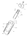
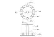
- the temperature calibration block 2 includes a plurality of cores, that is, a first metal core 21, a second metal core 22, a third metal core 23 and a fourth metal core.
- a metal core 24 is provided.
- Each of the metal cores 21 to 24 is made of a material having good thermal conductivity such as copper or aluminum and is formed in a substantially cylindrical shape with a different diameter. is inserted, the third metal core 23 is inserted into the inner diameter of the second metal core 22, and the fourth metal core 24 is inserted into the inner diameter of the third metal core 23 to form the temperature calibration block 2 is configured. That is, the temperature calibration block 2 has a plurality of substantially cylindrical cores with different diameters, and the inner core is inserted into the inner diameter of the outer core.
- the Peltier module 3 is a module having a Peltier element, which is a thermoelectric element.
- a Peltier element utilizes the Peltier effect, and is a semiconductor element in which one surface becomes a heat absorbing surface and the other surface becomes a heat radiating surface when direct current is passed through it. By reversing the direction of the current, the heat absorption surface and the heat dissipation surface are reversed.
- the Peltier module 3 is round and has a circular through-hole 3a in its substantially central portion, through which a lead wire (not shown) is led out.
- Such a Peltier module 3 is sandwiched and held by a lower holder 31 and an upper holder 32, which are Peltier holders, and attached to the temperature calibration block 2 side.
- the lower holder 31 and the upper holder 32 are made of, for example, an aluminum material having good thermal conductivity, and have a short cylindrical shape with a flange portion.
- the upper surface of the lower holder 31 has substantially the same shape as the surface of the Peltier module 3, a circular through hole 31a is formed in the substantially central portion, and a flange portion 31b is formed on the lower surface side. Further, the flange portion 31b is formed with screw holes and through holes for attaching and coupling the lower holder 31 to the temperature calibration block 2 side.
- the lower surface of the upper holder 32 has substantially the same shape as the surface of the Peltier module 3, a circular through hole 32a is formed in a substantially central portion, and a flange portion 32b is formed on the upper surface side.
- the flange portion 32b has a through hole through which a mounting screw SL for mounting and coupling the upper holder 32 to the temperature calibration block 2 with the Peltier module 3 sandwiched between the upper holder 32 and the lower holder 31 penetrates.
- a hole is formed.
- the heat transfer body Ht is heat transfer grease such as modified silicone, and it is desirable that this heat transfer grease is mixed with a metal or metal oxide filler having high thermal conductivity. As a result, a joint surface is formed between the Peltier module 3 and the lower holder 31 , and the heat of the Peltier module 3 can be efficiently transferred from the lower holder 31 to the temperature calibration block 2 .
- the temperature calibration block 2, Peltier module 3 and top plate 13 are mechanically coupled and thermally coupled. Therefore, the temperature calibration block 2 can be inserted and stored in the storage portion of the vacuum insulation container 1 or removed from the storage portion by gripping and operating the take-out handle 13a as described above. Further, the heat generated from the Peltier module 3 is transferred to the upper surface side of the temperature calibration block 2 via the lower holder 31 and radiated to the top plate 13 side via the upper holder 32 .
- the temperature calibration block 2 is housed in the vacuum insulation container 1 so as to be surrounded by the vacuum region Va of the vacuum insulation container 1, the temperature calibration block 2 is kept in a highly adiabatic state.
- the inner cylindrical portion 12 of the vacuum insulation container 1 constitutes a housing portion for housing the temperature calibration block 2.
- a vacuum region Va is formed around the outer circumference of this housing portion (inner cylindrical portion 12).
- a heat insulating material 4 is arranged so as to cover the inner cylindrical portion 12 of the housing portion. .
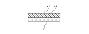
- the heat insulating material 4 has the function of a high-performance radiation shield, and the material of this heat insulating material 4 is, as shown in FIG.
- a radiation layer 43 having The radiation layer 43 is a resin layer made of polyester resin or the like.
- the thickness dimension of the base material layer 41 is about 7 ⁇ m to 11 ⁇ m
- the thickness dimension of the radiation layer 43 is about 9 ⁇ m to 15 ⁇ m
- the layer thickness dimension is about 16 ⁇ m to 26 ⁇ m.
- This material is a flexible sheet-like and tape-like one, is formed into a shape and the like so as to fit the vacuum area Va, and is laminated in multiple layers, specifically 10 to 20 layers. It is disposed so as to cover the cylindrical portion 12 by winding it. In order to effectively exhibit the function of the radiation shield, it is preferable to place the radiation layer 43 so as to face the inner cylindrical portion 12 .
- the top plate 13 is arranged in contact with the upper surface of the vacuum insulation container 1 .
- An insertion hole 13b for the reference thermometer 5 and a wiring lead-out hole 13c for taking out the wiring of the thermistor are formed in substantially the center of the top plate 13. As shown in FIG.
- the insertion hole 13b of the reference thermometer 5 is also used as a wiring lead-out hole for a thermistor that controls the temperature of the Peltier module 3, which will be described later.
- the temperature calibration block 2 is composed of a first metal core 21, a second metal core 22, a third metal core 23 and a fourth metal core 24.
- These metal cores 21, 22, 23, and 24 are substantially cylindrical, and an arrangement portion 25 elongated in the axial direction for the reference thermometer 5 as a reference temperature sensor and the thermistor as a temperature sensor to be calibrated is formed.
- the first metal core 21 is in the shape of a hollow cylinder with a bottom, and a pair of wiring lead-out grooves 211 having a small area and narrow width are formed in the upper end to face each other, and the fourth metal core 24 is positioned in the bottom. A recessed portion 212 is formed.
- the wiring lead-out groove 211 is mainly used as a path for leading wiring such as lead wires of a thermistor as a temperature sensor to be calibrated.
- the second metal core 22 has a hollow cylindrical shape, and a pair of narrow wiring lead-out grooves 221 having a small area are formed in the upper end of the annular ring so as to face each other.
- a plurality of insertion grooves 222 are formed throughout. Specifically, eight insertion grooves 222 are formed at equal intervals of 45 degrees on the circumference.
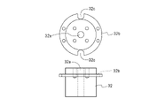
- the diameter of the outer periphery of the second metal core 22 is substantially the same as the diameter of the inner periphery of the first metal core 21, and the second metal core 22 is positioned within the inner periphery of the first metal core 21. It is adapted to be inserted in close contact. Accordingly, a thermistor placement portion 251 is formed by the insertion groove 222 of the second metal core 22 and the inner peripheral wall of the first metal core 21 (see FIG. 13(c)).
- the third metal core 23 is similarly hollow and cylindrical, and has a pair of wiring lead-out grooves 231 formed in the upper end of the annular ring so as to face each other. , an insertion groove 232 is formed. Eight insertion grooves 232 are formed at equal intervals of 45 degrees on the circumference.
- the diameter of the outer circumference of the third metal core 23 is substantially the same as the diameter of the inner circumference of the second metal core 22, and the third metal core 23 is positioned within the inner circumference of the second metal core 22. It is adapted to be inserted in close contact. Therefore, the insertion groove 232 of the third metal core 23 and the inner peripheral wall of the second metal core 22 form the thermistor placement portion 252 .
- the fourth metal core 24 has a substantially solid cylindrical shape, and has an insertion hole 240 formed in the central portion from the top end to the bottom, and an outer peripheral portion extending axially from the top to the bottom. A plurality of insertion grooves 242 are formed throughout.
- the insertion hole 240 functions as a placement portion 250 for the reference thermometer 5 .
- Four insertion grooves 242 are formed at equal intervals of 90 degrees on the circumference.
- the diameter of the outer periphery of the fourth metal core 24 is substantially the same as the diameter of the inner periphery of the third metal core 23, and the fourth metal core 24 is positioned within the inner periphery of the third metal core 23. It is adapted to be inserted in close contact.
- the insertion groove 242 of the fourth metal core 24 and the inner peripheral wall of the third metal core 23 form a thermistor placement portion 253 .
- a projection 243 is formed on the bottom of the fourth metal core 24, and is fitted into the positioning recess 212 of the first metal core 21 to determine the position.
- the relative relationship among the plurality of cores of the first metal core 21, the second metal core 22, the third metal core 23, and the fourth metal core 24 is the outer hollow cylindrical shape.
- the outer peripheral wall of the inner cylindrical core is in contact with the inner peripheral wall of the core, and the insertion groove of the inner core and the inner peripheral wall of the outer core form a placement portion 25 for the temperature sensor to be calibrated.
- the thermistor arrangement portions 251, 252 and 253 have different insertion opening sizes. Therefore, it is possible to arrange temperature sensors to be calibrated such as thermistors of different sizes and types.
- the insertion hole 240 of the fourth metal core 24 includes the through hole 31a of the lower holder 31 of the Peltier module 3, the through hole 3a of the Peltier module 3, the through hole 32a of the upper holder 32, and the insertion hole 13b of the top plate 13. It is continuously penetrating so that the reference thermometer 5 can be arranged from the insertion hole 13 b of the top plate 13 to the insertion hole 240 of the fourth metal core 24 .
- the Peltier module 3 is sandwiched between the lower holder 31 and the upper holder 32 and attached to the temperature calibration block 2 side as described above.
- the flange portion 31b of the lower holder 31 is formed with a pair of notches 31c that open outward. This notch 31c functions as a passage through which wiring of the thermistor as a temperature sensor to be calibrated passes.
- the lower holder 31 is formed with an arrangement hole 31d in which a temperature control thermistor (not shown) of the Peltier module 3 is arranged. 31 d of arrangement
- the temperature control thermistor has a function of sensing the temperature of the Peltier module 3 and controlling it to a predetermined temperature.
- the flange portion 32b of the upper holder 32 is similarly formed with a pair of notches 32c that open outward and face each other as passages for wiring of the thermistor.
- the vacuum region Va of the vacuum insulation container 1 is assumed to be in a vacuum state. Further, the temperature calibrating device 10 is connected to wiring led out from the temperature calibrating device 10 and is connected to control processing means such as a microcomputer for controlling the temperature calibrating device 10 .
- control processing means such as a microcomputer for controlling the temperature calibrating device 10 .
- the temperature calibration block 2 and the Peltier holder Separate the temperature calibration block 2 and the Peltier holder (lower holder 31 and upper holder 32 ), and place the thermistor of the temperature sensor to be calibrated and the reference thermometer 5 in the temperature calibration block 2 .
- the thermistor of the temperature sensor to be calibrated is inserted into the thermistor arrangement portion 25 and arranged, and the reference thermometer 5 is inserted into the arrangement portion 250 and arranged.
- the temperature measuring part of the reference thermometer 5 and the temperature measuring part of the thermistor should be located at substantially the same position in the axial direction (vertical direction), and should be near the bottoms of the respective metal cores 21, 22, 23 and 24. is desirable.
- the arrangement part 25 by putting a liquid such as silicone oil having insulating properties and good thermal conductivity into the arrangement part 25 and the arrangement part 250 and inserting the temperature sensor to be calibrated and the reference thermometer 5 therein, the arrangement part 25 Also, the internal temperature of the placement unit 250 can be made uniform to improve the accuracy of temperature calibration.
- a Peltier holder is fixed to the temperature calibration block 2, and the temperature calibration block 2 is housed in the housing portion of the vacuum insulation container 1 again. (4) Heat the Peltier module 3 to a predetermined temperature.
- the temperature calibration block 2 reaches a predetermined temperature (thermal equilibrium state), and the quasi-equilibrium state in the temperature state in the transition process of the gradual temperature rise is used as the calibration temperature. get the point
- a table of the temperature of the reference thermometer 5 and the resistance value of the thermistor of the temperature sensor to be calibrated ie, a calibration curve, is created to calibrate the temperature.
- the Peltier module 3 since the Peltier module 3 is used, the heat from the Peltier module 3 is transferred to the upper surface of the temperature calibration block 2 via the lower holder 31, and the temperature calibration block 2 is calibrated with a simple configuration. Control of the possible temperature distribution can be achieved in a short period of time. Moreover, even when the calibration temperature is lower or higher than the ambient temperature, the temperature distribution inside the temperature calibration block 2 can be significantly reduced.
- the temperature calibration block 2 is surrounded by the vacuum region Va of the vacuum insulation container 1, the synergistic effect of the heat insulation of the vacuum and the heat insulation of the heat insulating material 4 ensures high heat insulation. It is possible to achieve control in a short time so that the temperature calibration block 2 has a temperature distribution that can be calibrated.
- the thermistor of the reference thermometer 5 and the temperature sensor to be calibrated has a very low heat transfer coefficient on the outer periphery of the temperature calibration block 2 due to the axially long arrangement portion 25 in the axial direction and the vacuum region Va in the radial direction. Therefore, the Biot number of the temperature calibration block 2 is remarkably small. Therefore, the temperature distribution inside the temperature calibration block 2 is kept extremely uniform, so that the temperature sensor to be calibrated can be accurately calibrated.
- the temperatures of the upper and lower portions of the temperature calibration block 2 can be brought into a quasi-equilibrium state in a short time after starting the control of the Peltier module 3, and temperature calibration can be performed in a short time. Become.
- the temperature calibration block 2 can be controlled stepwise to different calibration temperatures, it is possible to continuously perform temperature calibration at a plurality of temperatures in one temperature calibration operation.
- the Peltier module is not limited to a round type. A rectangular one may also be used. Also, in the vicinity of normal temperature, temperature calibration is possible by the method of the above-described embodiment, but in temperature calibration at lower temperatures, the temperature calibration block is cooled by cooling the top plate with ice, dry ice, refrigerant, liquid nitrogen, etc. Low temperature calibration is possible at low temperature.
- the core that constitutes the temperature calibration block is preferably made of a metal material, but may be made of resin if a predetermined thermal conductivity can be secured. A resin mixed with a filler having a high thermal conductivity can be applied.
- Vacuum insulation container 2 Temperature calibration block 3: Temperature control means (Peltier module) 3a: through hole 4: heat insulating material 43: radiation layer 5: reference thermometer 10: temperature calibration device 101: control Processing means 11...Outer cylindrical portion 12...Inner cylindrical portion (accommodating portion) 13 Top plate 21 First metal core 22 Second metal core 23 Third metal core 24 Fourth Metal core 25 .. Arrangement portion 31 .. Peltier holder (lower holder) 32 Peltier holder (upper holder) 211, 221, 231... Wiring lead-out grooves 222, 232, 242... Insertion groove T... Temperature sensor to be calibrated (thin film thermistor) Va: vacuum region
Abstract
Provided is a temperature calibration method that makes it possible to efficiently calibrate temperature in a short time and enhance temperature calibration accuracy. This temperature calibration method uses a temperature calibration device (10) comprising a temperature calibration block (2) having formed therein a placement part (25) for a reference temperature sensor (5) and a temperature sensor (T) to be calibrated. In this temperature calibration method, a temperature state in a gradual temperature variation transition process of the temperature calibration block (2) is taken to be a calibration temperature. The temperature calibration device (10) comprises: a vacuum-insulated container (1) comprising a vacuum region (Va) surrounding the temperature calibration block (2) and an accommodation part for accommodating the temperature calibration block (2); and a Peltier module (3) that is thermally coupled to the temperature calibration block (2).
Description
本発明は、温度校正装置による温度校正方法に関する。
The present invention relates to a temperature calibration method using a temperature calibration device.
食品又は薬剤の製造のように安全性が重視される分野を含み、ほとんどの産業分野における製造工程では、温度を正確に制御する必要がある。また、最終的な製品品質に影響を与えかねない品質管理システムにおいても温度計測の正確性が重要となっている。
したがって、温度を制御したり計測したりするために用いられる温度センサを校正する必要がある。 Manufacturing processes in most industries, including safety-critical areas such as food or pharmaceutical manufacturing, require precise temperature control. Accurate temperature measurements are also important in quality control systems that can affect the final product quality.
Therefore, there is a need to calibrate temperature sensors that are used to control or measure temperature.
従来、温度センサとしての基準温度計及び被校正温度計によって温度を比較校正する温度校正装置が提案されている。この従来の温度校正装置は、基準温度計及び被校正温度計を、熱平衡状態の一定温度に保持された温度校正ブロックに配置して被校正温度計の温度を校正するものである。
Conventionally, temperature calibration devices have been proposed that compare and calibrate temperatures using a reference thermometer and a thermometer to be calibrated as temperature sensors. This conventional temperature calibrating device calibrates the temperature of the thermometer to be calibrated by arranging the reference thermometer and the thermometer to be calibrated in a temperature calibration block that is kept at a constant temperature in a thermal equilibrium state.
しかしながら、上記のような従来の温度校正方法では、温度校正ブロックを一定温度に保持する手段としては、液化ガス、冷凍機や電気ヒータ等が用いられており、温度校正ブロック内が熱平衡状態となるまでには、一般的に長い時間を要する。さらに、一定温度を保持するため、装置の構成が複雑化する虞がある。また、温度校正ブロックを一定及び一様の温度に保持する均熱化が難しいため、温度の校正精度は十分ではなく、温度の校正が効率的に行われないという問題が生じる。
However, in the conventional temperature calibration method as described above, a liquefied gas, a refrigerator, an electric heater, or the like is used as a means for maintaining the temperature calibration block at a constant temperature, and the inside of the temperature calibration block is in a state of thermal equilibrium. generally takes a long time. Furthermore, since a constant temperature is maintained, the configuration of the device may become complicated. In addition, since it is difficult to maintain the temperature of the temperature calibration block at a constant and uniform temperature, temperature calibration accuracy is insufficient and temperature calibration is not performed efficiently.
本発明の実施形態は、温度の多点校正を短時間で効率的に行うことができるとともに温度の多点を校正することで校正温度範囲の校正精度を向上することが可能な温度校正方法を提供することを目的とする。
Embodiments of the present invention provide a temperature calibration method that can efficiently perform multi-point temperature calibration in a short time and can improve the calibration accuracy of the calibration temperature range by calibrating multiple temperature points. intended to provide
本実施形態による温度校正方法は、基準温度センサ及び被校正温度センサの配置部が形成された温度校正ブロックを備える温度校正装置による温度校正方法であって、前記温度校正ブロックの漸次的な温度変化の移行過程における温度状態を校正温度とすることを特徴とする。
かかる実施形態の温度校正方法により、温度の校正を短時間で効率的に行うことができるとともに温度の校正精度を向上することが可能となる。 The temperature calibration method according to the present embodiment is a temperature calibration method using a temperature calibration device having a temperature calibration block in which a reference temperature sensor and a temperature sensor to be calibrated are arranged. The temperature state in the transition process of is used as the calibration temperature.
With the temperature calibration method of this embodiment, temperature calibration can be performed efficiently in a short period of time, and temperature calibration accuracy can be improved.
本発明の実施形態によれば、温度の校正を短時間で効率的に行うことができるとともに温度の校正精度を向上することが可能な温度校正方法を提供することができる。
According to the embodiment of the present invention, it is possible to provide a temperature calibration method capable of efficiently performing temperature calibration in a short time and improving the temperature calibration accuracy.
以下、本発明の実施形態に係る温度校正方法について図1乃至図6を参照して説明する。図1は、温度校正装置を示す構成図であり、図2は、被校正温度センサを示す斜視図及び断面図であり、図3及び図4は、温度校正方法の概念を説明するためのグラフである。図5は、温度校正方法を示すフロー図であり、図6は、被校正温度センサの温度校正データを示すグラフである。なお、図2では、各部を認識可能な大きさとするために、各部の縮尺を適宜変更している。
本実施形態の温度校正方法は、基準温度センサとしての基準温度計及び被校正温度センサとしてのサーミスタによって温度を比較校正するものである。 A temperature calibration method according to an embodiment of the present invention will be described below with reference to FIGS. 1 to 6. FIG. FIG. 1 is a configuration diagram showing a temperature calibration device, FIG. 2 is a perspective view and cross-sectional view showing a temperature sensor to be calibrated, and FIGS. 3 and 4 are graphs for explaining the concept of the temperature calibration method. is. FIG. 5 is a flow chart showing the temperature calibration method, and FIG. 6 is a graph showing temperature calibration data of the temperature sensor to be calibrated. In addition, in FIG. 2, the scale of each part is appropriately changed so that each part has a recognizable size.
The temperature calibration method of this embodiment is to compare and calibrate temperatures using a reference thermometer as a reference temperature sensor and a thermistor as a temperature sensor to be calibrated.
図1に示すように温度校正装置10は、温度校正ブロック2と、温度制御手段3とを備えている。また、温度校正装置10には制御処理手段101が接続されている。
As shown in FIG. 1, the temperature calibrating device 10 includes a temperature calibrating block 2 and temperature control means 3. A control processing means 101 is also connected to the temperature calibrating device 10 .
温度校正ブロック2は、高熱伝導率を有して熱伝導性が良好な材料から形成され、基準温度センサとしての基準温度計及び被校正温度センサとしてのサーミスタの配置部が形成されていて、基準温度計及びサーミスタが配置されるブロックである。
The temperature calibration block 2 is made of a material having high thermal conductivity and good thermal conductivity, and has a reference thermometer as a reference temperature sensor and a thermistor as a temperature sensor to be calibrated. This is the block where the thermometer and thermistor are placed.
温度制御手段3は、温度校正ブロック2と熱的に結合されており、温度校正ブロック2の温度を制御するものであり、例えば、ペルチェモジュールやヒータ等が用いられる。
The temperature control means 3 is thermally coupled with the temperature calibration block 2 and controls the temperature of the temperature calibration block 2. For example, a Peltier module, a heater, or the like is used.
制御処理手段101は、入力部及び出力部を有していて、温度校正ブロック2の温度を監視して制御したり、基準温度計及びサーミスタのデータを取得したりして、温度校正装置10全体の制御を実行する。
The control processing means 101 has an input part and an output part, monitors and controls the temperature of the temperature calibration block 2, acquires data of the reference thermometer and thermistor, and controls the temperature calibration device 10 as a whole. control of
図2に示すように被校正温度センサは、薄膜サーミスタTである。薄膜サーミスタTは、素子基板T11と、この基板T11上に形成された導電層T12と、薄膜素子層T13と、保護絶縁層T14とを備えている。
The temperature sensor to be calibrated is a thin film thermistor T as shown in FIG. The thin film thermistor T includes an element substrate T11, a conductive layer T12 formed on the substrate T11 , a thin film element layer T13 , and a protective insulating layer T14 .
素子基板T11は、略長方形状をなしていて、絶縁性のアルミナ材料で形成されている。なお、基板T11を形成する材料は、窒化アルミニウム、ジルコニア等のセラミックス又は半導体のシリコン、ゲルマニウム等の材料を用いてもよい。基板T11は極薄で厚さ寸法が50μm~150μm、好ましくは100μm以下に形成されている。
このような極薄の基板T11を薄膜サーミスタに用いることで、熱容量が小さくなり高感度で、かつ熱応答性の優れた感温素子の実現が可能となっている。 The element substrate T11 has a substantially rectangular shape and is made of an insulating alumina material. As the material for forming the substrate T11 , ceramics such as aluminum nitride and zirconia, or semiconductor materials such as silicon and germanium may be used. The substrate T11 is extremely thin and formed to have a thickness of 50 μm to 150 μm, preferably 100 μm or less.
By using such an ultra-thin substrate T11 for a thin film thermistor, it is possible to realize a thermosensitive element with reduced heat capacity, high sensitivity, and excellent thermal responsiveness.
導電層T12は、配線パターンを構成するものであり、基板T11上に形成されている。導電層T12は、金属薄膜をスパッタリング法によって成膜して形成されものである。また、基板T11の両端部には、導電層T12と一体的に、導電層T12と電気的に接続された一対の電極部T12aが形成されている。
The conductive layer T12 constitutes a wiring pattern and is formed on the substrate T11. The conductive layer T12 is formed by depositing a metal thin film by a sputtering method. A pair of electrode portions T12a electrically connected to the conductive layer T12 are formed integrally with the conductive layer T12 on both ends of the substrate T11.
薄膜素子層T13は、サーミスタ組成物であり、負の温度係数を有する酸化物半導体から構成されている。薄膜素子層T13は、前記導電層T12の上に、スパッタリング法等によって成膜して導電層T12と電気的に接続されている。なお、薄膜素子層は、正の温度係数を有する酸化物半導体から構成してもよい。保護絶縁層T14は、薄膜素子層T13及び導電層T12を被覆するように形成されている。保護絶縁層T14は、ホウケイ酸ガラスによって形成された保護ガラス層である。また、前記電極部T12aには、金属製のリード線T12bが溶接によって接合されて電気的に接続されている。
次に、図3及び図4を参照して温度校正方法の概念について説明する。 The thin film element layer T13 is a thermistor composition and is composed of an oxide semiconductor having a negative temperature coefficient. The thin film element layer T13 is formed on the conductive layer T12 by sputtering or the like, and is electrically connected to the conductive layer T12 . Note that the thin film element layer may be composed of an oxide semiconductor having a positive temperature coefficient. A protective insulating layer T14 is formed to cover the thin film element layer T13 and the conductive layer T12 . The protective insulating layer T14 is a protective glass layer made of borosilicate glass. A lead wire T12b made of metal is welded and electrically connected to the electrode portion T12a .
Next, the concept of the temperature calibration method will be described with reference to FIGS. 3 and 4. FIG.
図3において、横軸は時間(h)を示し、縦軸は温度校正ブロックの温度(℃)を示している。また、図中、左側は従来の温度校正方法を示し、右側は本実施形態の温度校正方法を示している。
In FIG. 3, the horizontal axis indicates time (h), and the vertical axis indicates the temperature (°C) of the temperature calibration block. In the figure, the left side shows the conventional temperature calibration method, and the right side shows the temperature calibration method of this embodiment.
まず、従来の温度校正方法は、温度校正ブロックの熱平衡状態で校正を行う定常比較法である。具体的には、温度校正ブロックの温度を例えば、30℃、35℃、40℃・・・に設定し、設定した一定の温度状態、つまり、熱平衡状態になるまで待機して校正を行うものである。したがって、定常比較法では、5℃ごとに30℃から60℃まで、7点で校正を行う場合、約20時間の時間を要することとなる。このように多点の校正には時間がかかるので一般的な温度校正は2点から6点校正が一般的に実施されている。
First, the conventional temperature calibration method is a stationary comparison method that performs calibration in the thermal equilibrium state of the temperature calibration block. Specifically, the temperature of the temperature calibration block is set to, for example, 30°C, 35°C, 40°C, etc., and calibration is performed after waiting until the set constant temperature state, that is, the thermal equilibrium state is reached. be. Therefore, in the steady-state comparison method, it takes about 20 hours when calibration is performed at 7 points from 30°C to 60°C every 5°C. Since multipoint calibration takes time, two to six point calibration is generally performed for general temperature calibration.
一方、本実施形態の温度校正方法は、温度校正ブロックが熱平衡状態に至ることなく、漸次的な温度変化の移行過程における温度状態で校正を行う非定常比較法である。したがって、温度校正ブロックの温度が熱平衡状態になるまで待機する必要はなく、温度校正ブロックを漸次的に異なる校正温度に制御して、短時間で校正を行うことが可能となる。なお、図においては、温度校正ブロックを自然冷却した場合の漸次的な温度変化の移行過程の温度カーブを示している。漸次的な温度変化の移行過程における温度状態で校正を行うことで10点以上の多点の校正が容易に実現できる。
On the other hand, the temperature calibration method of this embodiment is a non-stationary comparison method in which calibration is performed in the temperature state in the transition process of gradual temperature changes without the temperature calibration block reaching a thermal equilibrium state. Therefore, there is no need to wait until the temperature of the temperature calibration block reaches thermal equilibrium, and calibration can be performed in a short time by gradually controlling the temperature calibration block to different calibration temperatures. The figure shows a temperature curve of a gradual transition process of temperature change when the temperature calibration block is naturally cooled. By performing calibration in the temperature state in the transition process of gradual temperature change, multi-point calibration of 10 points or more can be easily realized.
本発明の漸次的な温度変化の移行過程における温度状態である図の温度カーブは60℃~30℃に冷却するときの時間は約30時間であり、1時間で1℃変化している。熱平衡状態ではないが校正する熱時定数の小さい温度センサに対しては熱平衡状態と同等の熱的な安定状態とみなすことができることを確認している。
The temperature curve in the figure, which is the temperature state in the transition process of the gradual temperature change of the present invention, takes about 30 hours to cool from 60°C to 30°C, and changes by 1°C per hour. It is confirmed that the temperature sensor with a small thermal time constant to be calibrated can be regarded as a thermally stable state equivalent to the thermal equilibrium state although it is not in the thermal equilibrium state.
図4において、横軸は時間を示し、縦軸は温度校正ブロックの温度(℃)を示しており、温度校正ブロックの漸次的な温度変化、つまり、昇温の場合又は降温の場合の温度の移行過程を示している。本実施形態の温度校正方法は、このように昇温の場合又は降温の場合の移行過程の温度を校正温度として校正を実行する。この温度校正ブロックの昇温状態又は降温状態は、温度制御手段3によって制御することが好ましいが、自然冷却によって降温状態とする場合であってもよい。
次に、温度校正方法の一例について図5を参照し説明する。 In FIG. 4, the horizontal axis indicates time, and the vertical axis indicates the temperature (°C) of the temperature calibration block. It shows the transition process. In the temperature calibration method of the present embodiment, calibration is performed using the temperature in the transition process in the case of temperature increase or temperature decrease as the calibration temperature. It is preferable that the temperature control means 3 control whether the temperature calibration block is raised or lowered.
Next, an example of the temperature calibration method will be described with reference to FIG.
温度校正ブロック2の配置部に基準温度計及び被校正温度センサとして薄膜サーミスタTを配置する(S1)。温度制御手段3の設定により温度校正ブロック2を所定の温度に昇温する(S2)。温度校正ブロック2は設定された所定の温度に昇温していく。この温度校正ブロック2が所定の温度に到達する(熱平衡状態)前における漸次的な温度上昇の移行過程における温度状態を校正温度とする。校正温度は多数の温度点(多点)をとらえて校正することが可能である(S3)。これは、薄膜サーミスタTは、熱時定数が小さく、熱応答性に優れていて、分解能が高いことに起因している。つまり、分解能に対応した多数の温度点での校正が可能となる。
A thin film thermistor T is placed as a reference thermometer and a temperature sensor to be calibrated in the placement part of the temperature calibration block 2 (S1). The temperature calibration block 2 is heated to a predetermined temperature by setting the temperature control means 3 (S2). The temperature calibration block 2 is heated to the set predetermined temperature. The temperature state in the transition process of gradual temperature rise before the temperature calibration block 2 reaches a predetermined temperature (thermal equilibrium state) is referred to as the calibration temperature. The calibration temperature can be calibrated by capturing a large number of temperature points (multiple points) (S3). This is because the thin film thermistor T has a small thermal time constant, excellent thermal responsiveness, and high resolution. That is, it is possible to calibrate at a large number of temperature points corresponding to the resolution.
次いで、基準温度計と被校正温度センサの薄膜サーミスタTとの関係、つまり、基準温度計の温度と薄膜サーミスタTの抵抗値との相関関係のデータを取得し(S4)、基準温度計の温度と被校正温度センサの薄膜サーミスタTの抵抗値の校正曲線を作成し温度校正を行う(S5)。
Then, the relationship between the reference thermometer and the thin-film thermistor T of the temperature sensor to be calibrated, that is, the data of the correlation between the temperature of the reference thermometer and the resistance value of the thin-film thermistor T is obtained (S4). Then, a calibration curve for the resistance value of the thin-film thermistor T of the temperature sensor to be calibrated is created to calibrate the temperature (S5).
なお、本例は、温度制御手段3の設定により温度校正ブロック2を昇温状態にする場合について説明したが、温度制御手段3の設定により温度校正ブロック2を降温状態にする場合であっても勿論適用可能である。
In this example, the case where the temperature calibration block 2 is raised in temperature by setting the temperature control means 3 has been described. Of course, it is applicable.
続いて、多数の温度点をとらえて校正する場合の校正データの一例について図6を参照して説明する。図6は温度校正ブロック(基準温度計)の40℃付近の詳細なデータを示すものであり、横軸は温度(℃)、縦軸は薄膜サーミスタTの抵抗値(Ω)を示している。校正データは、薄膜サーミスタTについて4回繰り返し測定した結果を示している。39.99℃~40.01℃の校正データであり、この温度範囲において40の温度点での校正が可能であることを示している。4回の繰り返し測定した結果では、各回の比較において微差に過ぎないことが分かる。
Next, an example of calibration data when calibrating by capturing a large number of temperature points will be described with reference to FIG. FIG. 6 shows detailed data around 40° C. of the temperature calibration block (reference thermometer), where the horizontal axis indicates temperature (° C.) and the vertical axis indicates the resistance value (Ω) of the thin film thermistor T. As shown in FIG. The calibration data shows the results of four repeated measurements of the thin film thermistor T. FIG. The calibration data are from 39.99° C. to 40.01° C., showing that calibration at 40 temperature points is possible in this temperature range. It can be seen from the results of four repeated measurements that there is only a slight difference in each comparison.
なお、本実施形態の非定常比較法による温度校正方法では、温度制御手段3の制御により1時間で1℃の温度変化が可能であり、この場合4000の温度点での校正が可能である。したがって、多数の温度点をとらえて連続的に校正することができ、校正精度を著しく向上することができる。また、例えば、サーミスタを用いる電子体温計では、温度範囲を32℃~42℃として40000の温度点での校正が可能である。
以上のように本実施形態によれば、温度の校正を短時間で効率的に行うことができるとともに温度の校正精度を向上することができる。 In the temperature calibration method based on the unsteady comparison method of this embodiment, the temperature can be changed by 1° C. per hour under the control of the temperature control means 3. In this case, calibration at 4000 temperature points is possible. Therefore, a large number of temperature points can be captured and continuously calibrated, and the calibration accuracy can be remarkably improved. Further, for example, an electronic thermometer using a thermistor can be calibrated at 40,000 temperature points with a temperature range of 32°C to 42°C.
As described above, according to the present embodiment, temperature calibration can be performed efficiently in a short time, and temperature calibration accuracy can be improved.
加えて、被校正温度センサとしてのサーミスタを顧客に提供する場合、サーミスタとともに、多数の温度点、例えば少なくとも20以上の温度点での温度校正データを付属して、温度校正データ付きサーミスタとして提供することにより、顧客の有効利用に資することができる。
In addition, when providing a thermistor as a temperature sensor to be calibrated to a customer, temperature calibration data at a large number of temperature points, for example, at least 20 temperature points, are attached together with the thermistor, and the thermistor is provided as a thermistor with temperature calibration data. By doing so, it is possible to contribute to the effective use of customers.
次に、本実施形態による温度校正方法を好適に実現する温度校正装置について図7乃至図18を参照して説明する。図7及び図8は、温度校正装置を示す斜視図及び分解斜視図であり、図9及び図10は、温度校正ブロック及びペルチェモジュールを取り出して示す斜視図及び分解斜視図であり、図11は、温度校正ブロックを示す分解斜視図である。図12は、温度校正装置を示す縦断面図及び上面図であり、図13は、温度校正装置を示す横断面図である。図14は、温度校正ブロックのコアを示す正面図及び上面図であり、図15及び図16は、ペルチェホルダを示す正面図及び上面図であり、図17は、断熱材を模式的に示す断面図である。また、図18は、温度校正ブロックの温度分布を示すグラフである。
なお、各図においてはリード線等の配線関係の図示は省略している。また、同一又は相当部分には同一符号を付し、重複する説明を省略している場合がある。 Next, a temperature calibrating device that suitably implements the temperature calibrating method according to this embodiment will be described with reference to FIGS. 7 to 18. FIG. 7 and 8 are a perspective view and an exploded perspective view showing the temperature calibration device, FIGS. 9 and 10 are a perspective view and an exploded perspective view showing the temperature calibration block and the Peltier module taken out, and FIG. 4 is an exploded perspective view showing a temperature calibration block; FIG. 12 is a longitudinal sectional view and a top view showing the temperature calibrating device, and FIG. 13 is a transverse sectional view showing the temperature calibrating device. 14 is a front view and a top view showing the core of the temperature calibration block, FIGS. 15 and 16 are a front view and a top view showing the Peltier holder, and FIG. 17 is a cross section schematically showing the heat insulating material. It is a diagram. Also, FIG. 18 is a graph showing the temperature distribution of the temperature calibration block.
In each figure, illustration of wiring relationships such as lead wires is omitted. Also, the same or corresponding parts are denoted by the same reference numerals, and redundant description may be omitted.
まず、図7乃至図11を参照して温度校正装置の基本的な構成について説明する。本実施形態の温度校正装置は、基準温度センサとしての基準温度計及び被校正温度センサとしてのサーミスタによって温度を比較校正するものである。基準温度計5は、国際温度目盛が定める方法に従い校正された白金抵抗温度計を用いている(図12参照)。また、サーミスタは、例えば薄膜サーミスタである。
First, the basic configuration of the temperature calibrating device will be described with reference to FIGS. 7 to 11. FIG. The temperature calibrating device of this embodiment compares and calibrate the temperature using a reference thermometer as a reference temperature sensor and a thermistor as a temperature sensor to be calibrated. The reference thermometer 5 uses a platinum resistance thermometer calibrated according to the method defined by the International Temperature Scale (see FIG. 12). Also, the thermistor is, for example, a thin film thermistor.
図7及び図8に示すように温度校正装置10は、真空断熱容器1と、この真空断熱容器1の中に収容される温度校正ブロック2と、温度制御手段としてのペルチェモジュール3とを備えている。温度校正装置10は、略円筒状をなしていて径寸法がφ150mmであり、高さ寸法が360mm程度の大きさである。
As shown in FIGS. 7 and 8, the temperature calibration device 10 comprises a vacuum insulation container 1, a temperature calibration block 2 housed in the vacuum insulation container 1, and a Peltier module 3 as temperature control means. there is The temperature calibration device 10 has a substantially cylindrical shape with a diameter of φ150 mm and a height of about 360 mm.
真空断熱容器1は、温度校正装置10の外観を構成するものであり、ステンレス鋼の薄肉材料により略円筒状に形成されていて、外円筒部11及び内円筒部12を有している。
The vacuum insulation container 1 constitutes the appearance of the temperature calibrating device 10, is formed in a substantially cylindrical shape from a thin stainless steel material, and has an outer cylindrical portion 11 and an inner cylindrical portion 12.
外円筒部11は、外周側壁11aと、この外周側壁11aの底面を形成する円形状の底壁11bと、外周側壁11aの上面を形成するリング状の上壁11cとによって構成されている。内円筒部12は、有底筒状であり、外周側壁12aと、外周側壁12aの底面を形成する円形状の底壁12bとによって構成され、上部に円形状の開口部12cが形成されている。この内円筒部12は、開口部12cの縁部が外円筒部11のリング状の上壁11cに溶接等によって接合されている。
The outer cylindrical portion 11 is composed of an outer peripheral side wall 11a, a circular bottom wall 11b forming the bottom surface of the outer peripheral side wall 11a, and a ring-shaped upper wall 11c forming the upper surface of the outer peripheral side wall 11a. The inner cylindrical portion 12 has a cylindrical shape with a bottom, and is composed of an outer peripheral side wall 12a and a circular bottom wall 12b forming the bottom surface of the outer peripheral side wall 12a, and a circular opening 12c is formed at the top. . The edge of the opening 12c of the inner cylindrical portion 12 is joined to the ring-shaped upper wall 11c of the outer cylindrical portion 11 by welding or the like.
したがって、外円筒部11と内円筒部12とによって、内円筒部12の外周側には、密閉的な空間領域、つまり、真空領域Vaが形成されるようになっている。外円筒部11の上部側には真空ポンプが接続される接続口としての真空フランジ11dが形成されている。この真空フランジ11dに真空ポンプを接続して、真空ポンプを動作させることにより真空領域Vaを真空状態とすることができる。なお、真空領域Vaには、後述する断熱材が配設されるようになっている。
Therefore, the outer cylindrical portion 11 and the inner cylindrical portion 12 form a closed spatial region, that is, a vacuum region Va on the outer peripheral side of the inner cylindrical portion 12 . A vacuum flange 11d is formed on the upper side of the outer cylindrical portion 11 as a connection port to which a vacuum pump is connected. By connecting a vacuum pump to the vacuum flange 11d and operating the vacuum pump, the vacuum area Va can be evacuated. A heat insulating material, which will be described later, is arranged in the vacuum area Va.
内円筒部12には、温度校正ブロック2と、この温度校正ブロック2と熱的に結合されるペルチェモジュール3とが連結された状態で挿入される。具体的には、温度校正ブロック2とペルチェモジュール3とが連結された部材230は、内円筒部12の開口部12cから底壁12bへ向かって挿入され配置される。
A temperature calibration block 2 and a Peltier module 3 thermally coupled to the temperature calibration block 2 are inserted into the inner cylindrical portion 12 in a connected state. Specifically, the member 230 connecting the temperature calibration block 2 and the Peltier module 3 is inserted from the opening 12c of the inner cylindrical portion 12 toward the bottom wall 12b.
また、部材230には、天板13が連結され固定されるようになっている。したがって、温度校正ブロック2、ペルチェモジュール3及び天板13は、ねじ等の固定手段によって一体的に連結され、また、熱的に結合されるようになっている。
In addition, the top plate 13 is connected and fixed to the member 230 . Therefore, the temperature calibration block 2, the Peltier module 3, and the top plate 13 are integrally connected and thermally coupled by fixing means such as screws.
天板13は、略円形状であり、アルミニウム合金等の熱伝導性が良好な材料で形成されていて、真空断熱容器1の上面に配置される。また、天板13には、略コ字状に形成された一対の取出しハンドル13aが設けられており、さらに、後述する配線の導出孔等が形成されている。
The top plate 13 has a substantially circular shape, is made of a material with good thermal conductivity such as an aluminum alloy, and is arranged on the upper surface of the vacuum insulation container 1 . Further, the top plate 13 is provided with a pair of take-out handles 13a formed in a substantially U-shape, and is further formed with a lead-out hole for wiring, etc., which will be described later.
したがって、内円筒部12は、真空断熱容器1における温度校正ブロック2を収容する収容部を構成しており、取出しハンドル13aを操作することにより、温度校正ブロック2を内円筒部12である収容部に挿入して収容したり、収容部から取り出したりすることができる。
Therefore, the inner cylindrical portion 12 constitutes a storage portion for storing the temperature calibration block 2 in the vacuum insulation container 1, and the temperature calibration block 2 can be removed from the storage portion, which is the inner cylindrical portion 12, by operating the extraction handle 13a. It can be inserted into and stored in the storage part, and can be taken out from the storage part.
図9乃至図11を併せて参照して示すように温度校正ブロック2は、高熱伝導率を有して熱伝導性が良好な材料から形成され、基準温度センサとしての基準温度計及び被校正温度センサとしてのサーミスタが配置されて、一定の温度に保持されるブロックである。
9 to 11, the temperature calibration block 2 is made of a material having high thermal conductivity and good thermal conductivity, and includes a reference thermometer as a reference temperature sensor and a temperature to be calibrated. It is a block in which a thermistor as a sensor is placed and kept at a constant temperature.
具体的には、図11に代表して示すように温度校正ブロック2は、複数のコア、すなわち、第1の金属コア21、第2の金属コア22、第3の金属コア23及び第4の金属コア24を備えている。各金属コア21~24は、銅やアルミニウム等の熱伝導性が良好な材料によって径寸法の異なる略円筒状に形成されていて、第1の金属コア21の内径内に第2の金属コア22が挿嵌され、第2の金属コア22の内径内に第3の金属コア23が挿嵌され、第3の金属コア23の内径内に第4の金属コア24が挿嵌されて温度校正ブロック2が構成される。つまり、温度校正ブロック2は、略円筒状の径寸法の異なる複数のコアを備えていて、外側のコアの内径内に内側のコアが挿嵌されている構成である。
Specifically, as representatively shown in FIG. 11, the temperature calibration block 2 includes a plurality of cores, that is, a first metal core 21, a second metal core 22, a third metal core 23 and a fourth metal core. A metal core 24 is provided. Each of the metal cores 21 to 24 is made of a material having good thermal conductivity such as copper or aluminum and is formed in a substantially cylindrical shape with a different diameter. is inserted, the third metal core 23 is inserted into the inner diameter of the second metal core 22, and the fourth metal core 24 is inserted into the inner diameter of the third metal core 23 to form the temperature calibration block 2 is configured. That is, the temperature calibration block 2 has a plurality of substantially cylindrical cores with different diameters, and the inner core is inserted into the inner diameter of the outer core.
ペルチェモジュール3は、熱電素子であるペルチェ素子を有するモジュールである。ペルチェ素子はペルチェ効果を利用するものであり、直流電流を流すことにより一方の面が吸熱面となり、他方の面が放熱面となる半導体素子である。電流の向きを逆転させることにより吸熱面と放熱面とが反転する。ペルチェモジュール3は、丸型であり略中央部に円形状の貫通孔3aを有し、図示しないリード線が導出されている。
The Peltier module 3 is a module having a Peltier element, which is a thermoelectric element. A Peltier element utilizes the Peltier effect, and is a semiconductor element in which one surface becomes a heat absorbing surface and the other surface becomes a heat radiating surface when direct current is passed through it. By reversing the direction of the current, the heat absorption surface and the heat dissipation surface are reversed. The Peltier module 3 is round and has a circular through-hole 3a in its substantially central portion, through which a lead wire (not shown) is led out.
このようなペルチェモジュール3は、ペルチェホルダである下ホルダ31及び上ホルダ32に挟持され保持されて温度校正ブロック2側に取り付けられる。下ホルダ31及び上ホルダ32は、熱伝導性が良好な例えば、アルミニウム材料から形成されていて、フランジ部を有して短円筒状をなしている。
Such a Peltier module 3 is sandwiched and held by a lower holder 31 and an upper holder 32, which are Peltier holders, and attached to the temperature calibration block 2 side. The lower holder 31 and the upper holder 32 are made of, for example, an aluminum material having good thermal conductivity, and have a short cylindrical shape with a flange portion.
下ホルダ31は、上面がペルチェモジュール3の面と略同一形状をなし、略中央部に円形状の貫通孔31aが形成され、下面側にはフランジ部31bが形成されている。また、フランジ部31bには、下ホルダ31を温度校正ブロック2側に取り付けて結合するためのねじ孔や貫通孔が形成されている。
The upper surface of the lower holder 31 has substantially the same shape as the surface of the Peltier module 3, a circular through hole 31a is formed in the substantially central portion, and a flange portion 31b is formed on the lower surface side. Further, the flange portion 31b is formed with screw holes and through holes for attaching and coupling the lower holder 31 to the temperature calibration block 2 side.
上ホルダ32は、下面がペルチェモジュール3の面と略同一形状をなし、略中央部に円形状の貫通孔32aが形成され、上面側にはフランジ部32bが形成されている。また、フランジ部32bには、上ホルダ32と下ホルダ31との間にペルチェモジュール3を挟んで、上ホルダ32を温度校正ブロック2側に取り付けて結合するための取付けねじSLが貫通する貫通孔が形成されている。
なお、下ホルダ31の上面及び下面には、伝熱体Htを設けるのが好ましい。具体的には、伝熱体Htは変性シリコーン等の伝熱グリスであり、この伝熱グリスに熱伝導率の高い金属や金属酸化物のフィラーを混入したものであることが望ましい。これによりペルチェモジュール3と下ホルダ31との接合面が形成され、ペルチェモジュール3の熱を下ホルダ31から温度校正ブロック2へと効率的に伝熱することができる。 The lower surface of theupper holder 32 has substantially the same shape as the surface of the Peltier module 3, a circular through hole 32a is formed in a substantially central portion, and a flange portion 32b is formed on the upper surface side. The flange portion 32b has a through hole through which a mounting screw SL for mounting and coupling the upper holder 32 to the temperature calibration block 2 with the Peltier module 3 sandwiched between the upper holder 32 and the lower holder 31 penetrates. A hole is formed.
In addition, it is preferable to provide heat transfer bodies Ht on the upper and lower surfaces of thelower holder 31 . Specifically, the heat transfer body Ht is heat transfer grease such as modified silicone, and it is desirable that this heat transfer grease is mixed with a metal or metal oxide filler having high thermal conductivity. As a result, a joint surface is formed between the Peltier module 3 and the lower holder 31 , and the heat of the Peltier module 3 can be efficiently transferred from the lower holder 31 to the temperature calibration block 2 .
なお、下ホルダ31の上面及び下面には、伝熱体Htを設けるのが好ましい。具体的には、伝熱体Htは変性シリコーン等の伝熱グリスであり、この伝熱グリスに熱伝導率の高い金属や金属酸化物のフィラーを混入したものであることが望ましい。これによりペルチェモジュール3と下ホルダ31との接合面が形成され、ペルチェモジュール3の熱を下ホルダ31から温度校正ブロック2へと効率的に伝熱することができる。 The lower surface of the
In addition, it is preferable to provide heat transfer bodies Ht on the upper and lower surfaces of the
再び、図7及び図8に代表して示すように温度校正ブロック2、ペルチェモジュール3及び天板13は、機械的に連結され熱的に結合されている。したがって、温度校正ブロック2は、既述のように取出しハンドル13aを把持して操作することにより、真空断熱容器1の収容部に挿入して収容したり、収容部から取り出したりすることができる。また、ペルチェモジュール3から発生する熱は、下ホルダ31を介して温度校正ブロック2の上面側へ伝熱され、一方、上ホルダ32を介して天板13側へ放熱される。
Again, as representatively shown in FIGS. 7 and 8, the temperature calibration block 2, Peltier module 3 and top plate 13 are mechanically coupled and thermally coupled. Therefore, the temperature calibration block 2 can be inserted and stored in the storage portion of the vacuum insulation container 1 or removed from the storage portion by gripping and operating the take-out handle 13a as described above. Further, the heat generated from the Peltier module 3 is transferred to the upper surface side of the temperature calibration block 2 via the lower holder 31 and radiated to the top plate 13 side via the upper holder 32 .
さらに、温度校正ブロック2は、真空断熱容器1の真空領域Vaに囲まれるように真空断熱容器1に収容されるので、温度校正ブロック2は高い断熱状態に保持されるようになる。
次に、図12乃至図18を参照して温度校正装置の詳細な構成について説明する。 Furthermore, since thetemperature calibration block 2 is housed in the vacuum insulation container 1 so as to be surrounded by the vacuum region Va of the vacuum insulation container 1, the temperature calibration block 2 is kept in a highly adiabatic state.
Next, the detailed configuration of the temperature calibrating device will be described with reference to FIGS. 12 to 18. FIG.
次に、図12乃至図18を参照して温度校正装置の詳細な構成について説明する。 Furthermore, since the
Next, the detailed configuration of the temperature calibrating device will be described with reference to FIGS. 12 to 18. FIG.
図12及び図13に示すように真空断熱容器1の内円筒部12は、温度校正ブロック2を収容する収容部を構成しており、この収容部(内円筒部12)の外周囲には、真空領域Vaが形成されている。また、真空領域Va内、詳しくは内円筒部12の外周囲と外円筒部11の内周囲との間には、収容部の内円筒部12を覆うように断熱材4が配設されている。
As shown in FIGS. 12 and 13, the inner cylindrical portion 12 of the vacuum insulation container 1 constitutes a housing portion for housing the temperature calibration block 2. Around the outer circumference of this housing portion (inner cylindrical portion 12), A vacuum region Va is formed. Further, in the vacuum region Va, more specifically, between the outer periphery of the inner cylindrical portion 12 and the inner periphery of the outer cylindrical portion 11, a heat insulating material 4 is arranged so as to cover the inner cylindrical portion 12 of the housing portion. .
断熱材4は、高性能の輻射シールドの機能を有し、この断熱材4の素材は、図17に示すように例えば、不織布の基材層41に、両面にアルミニウムが蒸着された反射層42を有する輻射層43が積層されて構成されている。輻射層43は樹脂層であり、ポリエステル樹脂等で形成されている。因みに、基材層41の厚さ寸法は7μm~11μm、輻射層43の厚さ寸法は9μm~15μmであり、層厚寸法は16μm~26μm程度である。
The heat insulating material 4 has the function of a high-performance radiation shield, and the material of this heat insulating material 4 is, as shown in FIG. A radiation layer 43 having The radiation layer 43 is a resin layer made of polyester resin or the like. Incidentally, the thickness dimension of the base material layer 41 is about 7 μm to 11 μm, the thickness dimension of the radiation layer 43 is about 9 μm to 15 μm, and the layer thickness dimension is about 16 μm to 26 μm.
この素材は可撓性を有するシート状であってテープ状のものであり、真空領域Vaに適合するように形状等を形成し、複数層、具体的には10層~20層重ねられて内円筒部12を巻回して覆うように配設されている。なお、輻射シールドの機能を効果的に発揮するためには、輻射層43側が内円筒部12側に対向するように配置するのが好ましい。
This material is a flexible sheet-like and tape-like one, is formed into a shape and the like so as to fit the vacuum area Va, and is laminated in multiple layers, specifically 10 to 20 layers. It is disposed so as to cover the cylindrical portion 12 by winding it. In order to effectively exhibit the function of the radiation shield, it is preferable to place the radiation layer 43 so as to face the inner cylindrical portion 12 .
天板13は、真空断熱容器1の上面に接触して配置されている。天板13の略中央部には、基準温度計5の挿入孔13bやサーミスタの配線を取り出す配線導出孔13cが形成されている。なお、基準温度計5の挿入孔13bは、後述するペルチェモジュール3の温度を制御するサーミスタの配線導出孔としても兼用されている。
The top plate 13 is arranged in contact with the upper surface of the vacuum insulation container 1 . An insertion hole 13b for the reference thermometer 5 and a wiring lead-out hole 13c for taking out the wiring of the thermistor are formed in substantially the center of the top plate 13. As shown in FIG. The insertion hole 13b of the reference thermometer 5 is also used as a wiring lead-out hole for a thermistor that controls the temperature of the Peltier module 3, which will be described later.
図14を併せて参照して示すように温度校正ブロック2は、第1の金属コア21、第2の金属コア22、第3の金属コア23及び第4の金属コア24から構成されている。これら金属コア21、22、23、24は略円筒状であり、基準温度センサとしての基準温度計5及び被校正温度センサとしてのサーミスタの軸方向に長い配置部25が形成されている。
As shown in conjunction with FIG. 14, the temperature calibration block 2 is composed of a first metal core 21, a second metal core 22, a third metal core 23 and a fourth metal core 24. These metal cores 21, 22, 23, and 24 are substantially cylindrical, and an arrangement portion 25 elongated in the axial direction for the reference thermometer 5 as a reference temperature sensor and the thermistor as a temperature sensor to be calibrated is formed.
第1の金属コア21は、有底の中空円筒状であり、上端部には対向して面積が小さく狭隘な一対の配線導出溝211が形成され、底部には第4の金属コア24の位置決め用凹部212が形成されている。配線導出溝211は、主として被校正温度センサとしてのサーミスタのリード線等の配線を取り出す通路として用いられる。
The first metal core 21 is in the shape of a hollow cylinder with a bottom, and a pair of wiring lead-out grooves 211 having a small area and narrow width are formed in the upper end to face each other, and the fourth metal core 24 is positioned in the bottom. A recessed portion 212 is formed. The wiring lead-out groove 211 is mainly used as a path for leading wiring such as lead wires of a thermistor as a temperature sensor to be calibrated.
第2の金属コア22は、中空円筒状であり、円環状の上端部には対向して面積が小さく狭隘な一対の配線導出溝221が形成され、外周部には軸方向に上部から底部に亘って複数の挿入溝222が形成されている。具体的には、挿入溝222は円周上45度の等間隔を空けて8つ形成されている。この第2の金属コア22の外周の径寸法は、第1の金属コア21の内周の径寸法と略同等であり、第2の金属コア22は第1の金属コア21の内周内に緊密に接触して挿嵌されるようになっている。したがって、第2の金属コア22の挿入溝222と第1の金属コア21の内周壁とによってサーミスタの配置部251が形成される(図13(c)参照)。
The second metal core 22 has a hollow cylindrical shape, and a pair of narrow wiring lead-out grooves 221 having a small area are formed in the upper end of the annular ring so as to face each other. A plurality of insertion grooves 222 are formed throughout. Specifically, eight insertion grooves 222 are formed at equal intervals of 45 degrees on the circumference. The diameter of the outer periphery of the second metal core 22 is substantially the same as the diameter of the inner periphery of the first metal core 21, and the second metal core 22 is positioned within the inner periphery of the first metal core 21. It is adapted to be inserted in close contact. Accordingly, a thermistor placement portion 251 is formed by the insertion groove 222 of the second metal core 22 and the inner peripheral wall of the first metal core 21 (see FIG. 13(c)).
第3の金属コア23は、同様に中空円筒状であり、円環状の上端部には対向して一対の配線導出溝231が形成され、外周部には軸方向に上部から底部に亘って複数の挿入溝232が形成されている。挿入溝232は円周上45度の等間隔を空けて8つ形成されている。この第3の金属コア23の外周の径寸法は、第2の金属コア22の内周の径寸法と略同等であり、第3の金属コア23は第2の金属コア22の内周内に緊密に接触して挿嵌されるようになっている。したがって、第3の金属コア23の挿入溝232と第2の金属コア22の内周壁とによってサーミスタの配置部252が形成される。
The third metal core 23 is similarly hollow and cylindrical, and has a pair of wiring lead-out grooves 231 formed in the upper end of the annular ring so as to face each other. , an insertion groove 232 is formed. Eight insertion grooves 232 are formed at equal intervals of 45 degrees on the circumference. The diameter of the outer circumference of the third metal core 23 is substantially the same as the diameter of the inner circumference of the second metal core 22, and the third metal core 23 is positioned within the inner circumference of the second metal core 22. It is adapted to be inserted in close contact. Therefore, the insertion groove 232 of the third metal core 23 and the inner peripheral wall of the second metal core 22 form the thermistor placement portion 252 .
第4の金属コア24は、概略としては中実円筒状であり、中央部に上端部から底部に亘って挿入孔240が形成されており、また、外周部には軸方向に上部から底部に亘って複数の挿入溝242が形成されている。挿入孔240は、基準温度計5の配置部250として機能する。挿入溝242は円周上90度の等間隔を空けて4つ形成されている。この第4の金属コア24の外周の径寸法は、第3の金属コア23の内周の径寸法と略同等であり、第4の金属コア24は第3の金属コア23の内周内に緊密に接触して挿嵌されるようになっている。したがって、第4の金属コア24の挿入溝242と第3の金属コア23の内周壁とによってサーミスタの配置部253が形成される。また、第4の金属コア24の底部には凸部243が形成されており、前記第1の金属コア21の位置決め用凹部212に嵌合して位置が定まるようになっている。
The fourth metal core 24 has a substantially solid cylindrical shape, and has an insertion hole 240 formed in the central portion from the top end to the bottom, and an outer peripheral portion extending axially from the top to the bottom. A plurality of insertion grooves 242 are formed throughout. The insertion hole 240 functions as a placement portion 250 for the reference thermometer 5 . Four insertion grooves 242 are formed at equal intervals of 90 degrees on the circumference. The diameter of the outer periphery of the fourth metal core 24 is substantially the same as the diameter of the inner periphery of the third metal core 23, and the fourth metal core 24 is positioned within the inner periphery of the third metal core 23. It is adapted to be inserted in close contact. Accordingly, the insertion groove 242 of the fourth metal core 24 and the inner peripheral wall of the third metal core 23 form a thermistor placement portion 253 . Further, a projection 243 is formed on the bottom of the fourth metal core 24, and is fitted into the positioning recess 212 of the first metal core 21 to determine the position.
以上のような構成において、第1の金属コア21、第2の金属コア22、第3の金属コア23及び第4の金属コア24の複数のコアの相対的な関係は、外側の中空円筒状のコアの内周壁に、内側の円筒状のコアの外周壁が接し、内側のコアの挿入溝と外側のコアの内周壁とによって被校正温度センサの配置部25が形成される関係にある。
In the configuration as described above, the relative relationship among the plurality of cores of the first metal core 21, the second metal core 22, the third metal core 23, and the fourth metal core 24 is the outer hollow cylindrical shape. The outer peripheral wall of the inner cylindrical core is in contact with the inner peripheral wall of the core, and the insertion groove of the inner core and the inner peripheral wall of the outer core form a placement portion 25 for the temperature sensor to be calibrated.
また、図13(c)に代表して示すように各サーミスタの配置部251、252及び253は、その挿入口の大きさが異なっている。したがって、サイズや種類の異なるサーミスタ等の被校正温度センサを配置することが可能となる。
Also, as representatively shown in FIG. 13(c), the thermistor arrangement portions 251, 252 and 253 have different insertion opening sizes. Therefore, it is possible to arrange temperature sensors to be calibrated such as thermistors of different sizes and types.
さらに、第4の金属コア24の挿入孔240は、ペルチェモジュール3の下ホルダ31の貫通孔31a、ペルチェモジュール3の貫通孔3a、上ホルダ32の貫通孔32a及び天板13の挿入孔13bと連続して貫通状態となっていて、基準温度計5を天板13の挿入孔13bから第4の金属コア24の挿入孔240へ配置できるようになっている。
Further, the insertion hole 240 of the fourth metal core 24 includes the through hole 31a of the lower holder 31 of the Peltier module 3, the through hole 3a of the Peltier module 3, the through hole 32a of the upper holder 32, and the insertion hole 13b of the top plate 13. It is continuously penetrating so that the reference thermometer 5 can be arranged from the insertion hole 13 b of the top plate 13 to the insertion hole 240 of the fourth metal core 24 .
さらにまた、各配線導出溝211、221及び231から被校正温度センサとしてのサーミスタのリード線等の配線が外部へ取り出されるので、配線を通じてサーミスタから温度校正ブロック2に熱が侵入するのを抑制することができる。
Furthermore, since wiring such as lead wires of the thermistor as a temperature sensor to be calibrated is taken out from each of the wiring lead-out grooves 211, 221 and 231, heat is prevented from entering the temperature calibration block 2 from the thermistor through the wiring. be able to.
ペルチェモジュール3は、既述のように下ホルダ31及び上ホルダ32に挟持されて温度校正ブロック2側に取り付けられる。図15に示すように下ホルダ31のフランジ部31bには、対向して一対の外側へ開放する切欠き31cが形成されている。この切欠き31cは、被校正温度センサとしてのサーミスタの配線が通る通路として機能する。また、下ホルダ31には、ペルチェモジュール3の図示しない温度制御用サーミスタが配置される配置孔31dが形成されている。配置孔31dは外周から中央部へ向かって貫通孔31aまで形成されている。温度制御用サーミスタは、ペルチェモジュール3の温度を感知し所定の温度に制御する機能を有している。
The Peltier module 3 is sandwiched between the lower holder 31 and the upper holder 32 and attached to the temperature calibration block 2 side as described above. As shown in FIG. 15, the flange portion 31b of the lower holder 31 is formed with a pair of notches 31c that open outward. This notch 31c functions as a passage through which wiring of the thermistor as a temperature sensor to be calibrated passes. Further, the lower holder 31 is formed with an arrangement hole 31d in which a temperature control thermistor (not shown) of the Peltier module 3 is arranged. 31 d of arrangement|positioning holes are formed to the through-hole 31a toward the center part from the outer periphery. The temperature control thermistor has a function of sensing the temperature of the Peltier module 3 and controlling it to a predetermined temperature.
図16に示すように上ホルダ32のフランジ部32bには、同様にサーミスタの配線が通る通路として、対向して一対の外側へ開放する切欠き32cが形成されている。
As shown in FIG. 16, the flange portion 32b of the upper holder 32 is similarly formed with a pair of notches 32c that open outward and face each other as passages for wiring of the thermistor.
次に、温度校正装置10の使用手順(温度校正方法)について、主として図12を参照して説明する。まず、前提として真空断熱容器1の真空領域Vaは真空状態となっているものとする。また、温度校正装置10には、温度校正装置10から導出される配線が接続され、温度校正装置10の制御を実行するマイクロコンピュータ等の制御処理手段が接続されている。
(1)天板13の取出しハンドル13a把持して操作し、温度校正ブロック2を真空断熱容器1の収容部から取り出す。 Next, the procedure for using the temperature calibrating device 10 (temperature calibrating method) will be described mainly with reference to FIG. First, as a premise, the vacuum region Va of thevacuum insulation container 1 is assumed to be in a vacuum state. Further, the temperature calibrating device 10 is connected to wiring led out from the temperature calibrating device 10 and is connected to control processing means such as a microcomputer for controlling the temperature calibrating device 10 .
(1) Take-out handle 13a of top plate 13 is gripped and manipulated to take out temperature calibration block 2 from storage portion of vacuum insulation container 1.
(1)天板13の取出しハンドル13a把持して操作し、温度校正ブロック2を真空断熱容器1の収容部から取り出す。 Next, the procedure for using the temperature calibrating device 10 (temperature calibrating method) will be described mainly with reference to FIG. First, as a premise, the vacuum region Va of the
(1) Take-
(2)温度校正ブロック2とペルチェホルダ(下ホルダ31及び上ホルダ32)とを分離し、温度校正ブロック2に被校正温度センサのサーミスタ及び基準温度計5を配置する。具体的には、被校正温度センサのサーミスタをサーミスタの配置部25に挿入して配置するとともに、基準温度計5を配置部250に挿入して配置する。この場合、基準温度計5の測温部とサーミスタの測温部とは、軸方向(垂直方向)において略同位置に位置され、各金属コア21、22、23及び24の底部近傍であることが望ましい。また、配置部25及び配置部250に、絶縁性及び良好な熱伝導性を有するシリコーンオイル等の液体を入れ、その中に被校正温度センサ及び基準温度計5を挿入することにより、配置部25及び配置部250の内部温度を均一にして温度校正の精度を向上させることができる。
(3)温度校正ブロック2にペルチェホルダを固定し、再び温度校正ブロック2を真空断熱容器1の収容部に収容する。
(4)ペルチェモジュール3を加熱し、所定の温度まで昇温する。 (2) Separate thetemperature calibration block 2 and the Peltier holder (lower holder 31 and upper holder 32 ), and place the thermistor of the temperature sensor to be calibrated and the reference thermometer 5 in the temperature calibration block 2 . Specifically, the thermistor of the temperature sensor to be calibrated is inserted into the thermistor arrangement portion 25 and arranged, and the reference thermometer 5 is inserted into the arrangement portion 250 and arranged. In this case, the temperature measuring part of the reference thermometer 5 and the temperature measuring part of the thermistor should be located at substantially the same position in the axial direction (vertical direction), and should be near the bottoms of the respective metal cores 21, 22, 23 and 24. is desirable. In addition, by putting a liquid such as silicone oil having insulating properties and good thermal conductivity into the arrangement part 25 and the arrangement part 250 and inserting the temperature sensor to be calibrated and the reference thermometer 5 therein, the arrangement part 25 Also, the internal temperature of the placement unit 250 can be made uniform to improve the accuracy of temperature calibration.
(3) A Peltier holder is fixed to thetemperature calibration block 2, and the temperature calibration block 2 is housed in the housing portion of the vacuum insulation container 1 again.
(4) Heat thePeltier module 3 to a predetermined temperature.
(3)温度校正ブロック2にペルチェホルダを固定し、再び温度校正ブロック2を真空断熱容器1の収容部に収容する。
(4)ペルチェモジュール3を加熱し、所定の温度まで昇温する。 (2) Separate the
(3) A Peltier holder is fixed to the
(4) Heat the
(5)ペルチェモジュール3の加熱により、温度校正ブロック2が所定の温度に到達する(熱平衡状態)前における漸次的な温度上昇の移行過程における温度状態で準平衡状態を校正温度として、多数の温度点をとらえる。
(5) By heating the Peltier module 3, the temperature calibration block 2 reaches a predetermined temperature (thermal equilibrium state), and the quasi-equilibrium state in the temperature state in the transition process of the gradual temperature rise is used as the calibration temperature. get the point
(6)温度校正ブロック2(基準温度計5)と被校正温度センサのサーミスタとの関係、つまり、基準温度計5の温度(校正温度)とサーミスタの抵抗値との相関関係のデータを取得する。なお、その後、ペルチェモジュール3の加熱温度を再度制御し、温度校正ブロック2を例えば、段階的に異なる校正温度に制御してもよい。
(6) Acquire data on the relationship between the temperature calibration block 2 (reference thermometer 5) and the thermistor of the temperature sensor to be calibrated, that is, the correlation data between the temperature (calibration temperature) of the reference thermometer 5 and the resistance value of the thermistor. . After that, the heating temperature of the Peltier module 3 may be controlled again, and the temperature calibration block 2 may be controlled, for example, to a stepwise different calibration temperature.
(7)前記(6)の操作を繰り返し実行し、基準温度計5の温度と被校正温度センサのサーミスタの抵抗値のテーブル表、すなわち、校正曲線を作成し温度校正を行う。
以上のように本実施形態によれば、簡単な構成で、温度の校正精度を向上できるとともに効率的な温度の校正を行うことが可能となる。 (7) By repeating the operation in (6) above, a table of the temperature of thereference thermometer 5 and the resistance value of the thermistor of the temperature sensor to be calibrated, ie, a calibration curve, is created to calibrate the temperature.
As described above, according to the present embodiment, it is possible to improve the accuracy of temperature calibration and to perform efficient temperature calibration with a simple configuration.
以上のように本実施形態によれば、簡単な構成で、温度の校正精度を向上できるとともに効率的な温度の校正を行うことが可能となる。 (7) By repeating the operation in (6) above, a table of the temperature of the
As described above, according to the present embodiment, it is possible to improve the accuracy of temperature calibration and to perform efficient temperature calibration with a simple configuration.
具体的には、ペルチェモジュール3を用いているので、ペルチェモジュール3からの熱は、下ホルダ31を経由して温度校正ブロック2の上面に伝熱され、簡単な構成により温度校正ブロック2の校正可能な温度分布にする制御を短時間で達成することができる。また、校正温度が環境温度より低い場合や高い場合でも温度校正ブロック2内部の温度分布を著しく小さくすることができる。
Specifically, since the Peltier module 3 is used, the heat from the Peltier module 3 is transferred to the upper surface of the temperature calibration block 2 via the lower holder 31, and the temperature calibration block 2 is calibrated with a simple configuration. Control of the possible temperature distribution can be achieved in a short period of time. Moreover, even when the calibration temperature is lower or higher than the ambient temperature, the temperature distribution inside the temperature calibration block 2 can be significantly reduced.
さらに、温度校正ブロック2は、真空断熱容器1の真空領域Vaに囲まれるようになっているので、真空の断熱性と断熱材4による断熱性との相乗効果により、高い断熱性が確保され、温度校正ブロック2を校正可能な温度分布にする制御を短時間で達成することが可能となる。
Furthermore, since the temperature calibration block 2 is surrounded by the vacuum region Va of the vacuum insulation container 1, the synergistic effect of the heat insulation of the vacuum and the heat insulation of the heat insulating material 4 ensures high heat insulation. It is possible to achieve control in a short time so that the temperature calibration block 2 has a temperature distribution that can be calibrated.
基準温度計5及び被校正温度センサのサーミスタは、軸方向については軸方向に長い配置部25により、半径方向については真空領域Vaによって温度校正ブロック2の外周の熱伝達率は非常に小さく抑えられて、温度校正ブロック2のビオ数は著しく小さくなっている。そのために、温度校正ブロック2の内部の温度分布は非常に均質に保たれることから、被校正温度センサの温度校正を正確に実施することができる。
The thermistor of the reference thermometer 5 and the temperature sensor to be calibrated has a very low heat transfer coefficient on the outer periphery of the temperature calibration block 2 due to the axially long arrangement portion 25 in the axial direction and the vacuum region Va in the radial direction. Therefore, the Biot number of the temperature calibration block 2 is remarkably small. Therefore, the temperature distribution inside the temperature calibration block 2 is kept extremely uniform, so that the temperature sensor to be calibrated can be accurately calibrated.
図18に示すようにペルチェモジュール3の制御を開始してから短時間で温度校正ブロック2の上部と下部の温度を準平衡状態にすることができ、短時間で温度校正を行うことが可能となる。
加えて、温度校正ブロック2を段階的に異なる校正温度に制御することができるので、複数温度の温度校正が1回の温度校正の操作で連続的に実施可能となる。 As shown in FIG. 18, the temperatures of the upper and lower portions of thetemperature calibration block 2 can be brought into a quasi-equilibrium state in a short time after starting the control of the Peltier module 3, and temperature calibration can be performed in a short time. Become.
In addition, since thetemperature calibration block 2 can be controlled stepwise to different calibration temperatures, it is possible to continuously perform temperature calibration at a plurality of temperatures in one temperature calibration operation.
加えて、温度校正ブロック2を段階的に異なる校正温度に制御することができるので、複数温度の温度校正が1回の温度校正の操作で連続的に実施可能となる。 As shown in FIG. 18, the temperatures of the upper and lower portions of the
In addition, since the
なお、上記温度校正装置ついて、例えば、ペルチェモジュールは丸型のものに限らない。角型のものを用いてもよい。また、常温近傍では上述の実施形態の方法で温度校正が可能であるが、より低温の温度校正では、天板を氷やドライアイス、冷媒、液体窒素などで冷却することにより、温度校正ブロックを低温にして低温の温度校正が可能となる。
Regarding the above temperature calibration device, for example, the Peltier module is not limited to a round type. A rectangular one may also be used. Also, in the vicinity of normal temperature, temperature calibration is possible by the method of the above-described embodiment, but in temperature calibration at lower temperatures, the temperature calibration block is cooled by cooling the top plate with ice, dry ice, refrigerant, liquid nitrogen, etc. Low temperature calibration is possible at low temperature.
さらに、温度校正ブロックを構成するコアは、金属材料が好ましいが、所定の熱伝導率が確保できれば樹脂であってもよい。樹脂に熱伝導率の高いフィラーを混入したものが適用できる。
Furthermore, the core that constitutes the temperature calibration block is preferably made of a metal material, but may be made of resin if a predetermined thermal conductivity can be secured. A resin mixed with a filler having a high thermal conductivity can be applied.
本発明は、上記実施形態に限定されることなく、発明の要旨を逸脱しない範囲で種々の変形が可能である。また、上記実施形態は、一例として提示したものであり、発明の範囲を限定することは意図していない。これら新規な実施形態は、その他の様々な形態で実施されることが可能であり、種々の省略、置き換え、変更を行うことができる。これら実施形態やその変形は、発明の範囲や要旨に含まれるとともに、特許請求の範囲に記載された発明とその均等の範囲に含まれる。
The present invention is not limited to the above embodiments, and various modifications are possible without departing from the scope of the invention. Moreover, the above-described embodiment is presented as an example and is not intended to limit the scope of the invention. These novel embodiments can be embodied in various other forms, and various omissions, substitutions and alterations can be made. These embodiments and modifications thereof are included in the scope and gist of the invention, and are included in the scope of the invention described in the claims and equivalents thereof.
1・・・・・・真空断熱容器
2・・・・・・温度校正ブロック
3・・・・・・温度制御手段(ペルチェモジュール)
3a・・・・・貫通孔
4・・・・・・断熱材
43・・・・・輻射層
5・・・・・・基準温度計
10・・・・・温度校正装置
101・・・・制御処理手段
11・・・・・外円筒部
12・・・・・内円筒部(収容部)
13・・・・・天板
21・・・・・第1の金属コア
22・・・・・第2の金属コア
23・・・・・第3の金属コア
24・・・・・第4の金属コア
25・・・・・配置部
31・・・・・ペルチェホルダ(下ホルダ)
32・・・・・ペルチェホルダ(上ホルダ)
211、221、231・・・配線導出溝
222、232、242・・・挿入溝
T・・・・・・被校正温度センサ(薄膜サーミスタ)
Va・・・・・真空領域 1: Vacuum insulation container 2: Temperature calibration block 3: Temperature control means (Peltier module)
3a: through hole 4: heat insulating material 43: radiation layer 5: reference thermometer 10: temperature calibration device 101: control Processing means 11...Outercylindrical portion 12...Inner cylindrical portion (accommodating portion)
13Top plate 21 First metal core 22 Second metal core 23 Third metal core 24 Fourth Metal core 25 .. Arrangement portion 31 .. Peltier holder (lower holder)
32 Peltier holder (upper holder)
211, 221, 231... Wiring lead-out grooves 222, 232, 242... Insertion groove T... Temperature sensor to be calibrated (thin film thermistor)
Va: vacuum region
2・・・・・・温度校正ブロック
3・・・・・・温度制御手段(ペルチェモジュール)
3a・・・・・貫通孔
4・・・・・・断熱材
43・・・・・輻射層
5・・・・・・基準温度計
10・・・・・温度校正装置
101・・・・制御処理手段
11・・・・・外円筒部
12・・・・・内円筒部(収容部)
13・・・・・天板
21・・・・・第1の金属コア
22・・・・・第2の金属コア
23・・・・・第3の金属コア
24・・・・・第4の金属コア
25・・・・・配置部
31・・・・・ペルチェホルダ(下ホルダ)
32・・・・・ペルチェホルダ(上ホルダ)
211、221、231・・・配線導出溝
222、232、242・・・挿入溝
T・・・・・・被校正温度センサ(薄膜サーミスタ)
Va・・・・・真空領域 1: Vacuum insulation container 2: Temperature calibration block 3: Temperature control means (Peltier module)
3a: through hole 4: heat insulating material 43: radiation layer 5: reference thermometer 10: temperature calibration device 101: control Processing means 11...Outer
13
32 Peltier holder (upper holder)
211, 221, 231... Wiring lead-out
Va: vacuum region
Claims (11)
- 基準温度センサ及び被校正温度センサの配置部が形成された温度校正ブロックを備える温度校正装置による温度校正方法であって、
前記温度校正ブロックの漸次的な温度変化の移行過程における温度状態を校正温度とすることを特徴とする温度校正方法。 A temperature calibration method using a temperature calibration device comprising a temperature calibration block in which a reference temperature sensor and a temperature sensor to be calibrated are arranged,
A temperature calibrating method, wherein the temperature state of the temperature calibrating block in the transition process of the gradual temperature change is used as the calibrating temperature. - 前記温度校正装置は、前記温度校正ブロックを囲むように真空領域を有し、前記温度校正ブロックを収容する収容部が設けられた真空断熱容器と、前記温度校正ブロックと熱的に結合されるペルチェモジュールと、を具備することを特徴とする請求項1に記載の温度校正方法。 The temperature calibration device has a vacuum area surrounding the temperature calibration block, and includes a vacuum insulation container provided with a storage portion for storing the temperature calibration block, and a Peltier thermally coupled with the temperature calibration block. The temperature calibration method according to claim 1, comprising: a module.
- 前記真空領域には、断熱材が配設されていることを特徴とする請求項2に記載の温度校正方法。 The temperature calibration method according to claim 2, characterized in that a heat insulating material is arranged in the vacuum area.
- 前記断熱材の素材は、可撓性を有し輻射層を備えていて、複数層重ねられて断熱材が構成されていることを特徴とする請求項3に記載の温度校正方法。 The temperature calibration method according to claim 3, wherein the material of the heat insulating material is flexible and has a radiation layer, and the heat insulating material is constructed by stacking a plurality of layers.
- 前記温度校正ブロックは、略円筒状の径寸法の異なる複数のコアを備えていて、外側のコアの内径内に内側のコアが挿嵌されて構成されていることを特徴とする請求項1乃至請求項4のいずれか一項に記載の温度校正方法。 1. The temperature calibration block comprises a plurality of substantially cylindrical cores with different diameters, wherein the inner core is inserted into the inner diameter of the outer core. The temperature calibration method according to claim 4.
- 前記内側のコアの外周部には、軸方向に挿入溝が形成されており、この挿入溝と外側のコアの内周壁とによって、前記被校正温度センサの配置部が形成されていることを特徴とする請求項5に記載の温度校正方法。 An insertion groove is formed in the outer peripheral portion of the inner core in the axial direction, and the insertion groove and the inner peripheral wall of the outer core form a placement portion for the temperature sensor to be calibrated. The temperature calibration method according to claim 5, wherein
- 前記被校正温度センサの配置部は複数形成されており、前記配置部の挿入口の大きさが異なっていることを特徴とする請求項6に記載の温度校正方法。 The temperature calibration method according to claim 6, wherein a plurality of placement portions for the temperature sensor to be calibrated are formed, and the sizes of the insertion openings of the placement portions are different.
- 前記コアの上端部には配線導出溝が形成されていることを特徴とする請求項5乃至請求項7のいずれか一項に記載の温度校正方法。 The temperature calibration method according to any one of claims 5 to 7, characterized in that a wiring lead-out groove is formed in the upper end of the core.
- 前記温度校正ブロックの配置部に基準温度センサ及び被校正温度センサが配置された状態において、基準温度センサの測温部及び被校正温度センサの測温部は、軸方向において略同位置となることを特徴とする請求項1乃至請求項8のいずれか一項に記載の温度校正方法。 In a state in which the reference temperature sensor and the temperature sensor to be calibrated are arranged in the arrangement portion of the temperature calibration block, the temperature measuring portion of the reference temperature sensor and the temperature measuring portion of the temperature sensor to be calibrated are at approximately the same position in the axial direction. The temperature calibration method according to any one of claims 1 to 8, characterized by:
- 前記ペルチェモジュールは、略中央部に貫通孔が形成されていることを特徴とする請求項2乃至請求項4のいずれか一項に記載の温度校正方法。 The temperature calibration method according to any one of claims 2 to 4, characterized in that the Peltier module has a through hole formed substantially in the center.
- 前記ペルチェモジュールは、ペルチェホルダによって保持され、ペルチェモジュールからの熱はペルチェホルダを介して前記温度校正ブロックへ伝熱されることを特徴とする請求項2に記載の温度校正方法。 The temperature calibration method according to claim 2, wherein the Peltier module is held by a Peltier holder, and heat from the Peltier module is transferred to the temperature calibration block via the Peltier holder.
Priority Applications (1)
| Application Number | Priority Date | Filing Date | Title |
|---|---|---|---|
| CN202280030959.2A CN117203508A (en) | 2021-05-21 | 2022-03-24 | Temperature correction method |
Applications Claiming Priority (2)
| Application Number | Priority Date | Filing Date | Title |
|---|---|---|---|
| JP2021-086036 | 2021-05-21 | ||
| JP2021086036A JP7339983B2 (en) | 2021-05-21 | 2021-05-21 | Temperature calibration method |
Publications (1)
| Publication Number | Publication Date |
|---|---|
| WO2022244464A1 true WO2022244464A1 (en) | 2022-11-24 |
Family
ID=84141193
Family Applications (1)
| Application Number | Title | Priority Date | Filing Date |
|---|---|---|---|
| PCT/JP2022/013936 WO2022244464A1 (en) | 2021-05-21 | 2022-03-24 | Temperature calibration method |
Country Status (3)
| Country | Link |
|---|---|
| JP (1) | JP7339983B2 (en) |
| CN (1) | CN117203508A (en) |
| WO (1) | WO2022244464A1 (en) |
Citations (4)
| Publication number | Priority date | Publication date | Assignee | Title |
|---|---|---|---|---|
| JP2007248277A (en) * | 2006-03-16 | 2007-09-27 | National Institute Of Advanced Industrial & Technology | Low temperature calibrating device for thermometer |
| JP2012013496A (en) * | 2010-05-31 | 2012-01-19 | Chino Corp | Soaking block for thermostatic devices |
| JP2016191566A (en) * | 2015-03-30 | 2016-11-10 | 株式会社岡崎製作所 | Low-temperature comparison/calibration apparatus |
| US20210123822A1 (en) * | 2019-10-28 | 2021-04-29 | Beamex Oy Ab | Detecting and indicating stability in an industrial temperature dry block calibrator |
-
2021
- 2021-05-21 JP JP2021086036A patent/JP7339983B2/en active Active
-
2022
- 2022-03-24 WO PCT/JP2022/013936 patent/WO2022244464A1/en active Application Filing
- 2022-03-24 CN CN202280030959.2A patent/CN117203508A/en active Pending
Patent Citations (4)
| Publication number | Priority date | Publication date | Assignee | Title |
|---|---|---|---|---|
| JP2007248277A (en) * | 2006-03-16 | 2007-09-27 | National Institute Of Advanced Industrial & Technology | Low temperature calibrating device for thermometer |
| JP2012013496A (en) * | 2010-05-31 | 2012-01-19 | Chino Corp | Soaking block for thermostatic devices |
| JP2016191566A (en) * | 2015-03-30 | 2016-11-10 | 株式会社岡崎製作所 | Low-temperature comparison/calibration apparatus |
| US20210123822A1 (en) * | 2019-10-28 | 2021-04-29 | Beamex Oy Ab | Detecting and indicating stability in an industrial temperature dry block calibrator |
Also Published As
| Publication number | Publication date |
|---|---|
| CN117203508A (en) | 2023-12-08 |
| JP7339983B2 (en) | 2023-09-06 |
| JP2022178910A (en) | 2022-12-02 |
Similar Documents
| Publication | Publication Date | Title |
|---|---|---|
| TWI801366B (en) | Non-contact temperature calibration tool for a substrate support and method of using the same | |
| US8814428B2 (en) | Temperature sensing apparatus | |
| JP4579993B2 (en) | Differential scanning calorimeter (DSC) with temperature controlled furnace | |
| US7537377B2 (en) | Thermal cycler for PCR | |
| US8496374B2 (en) | Differential scanning calorimeter | |
| KR20170088352A (en) | Electrostatic chuck device | |
| KR20080012329A (en) | Heated pressure transducer | |
| JP2011185697A (en) | Thermoelectric material evaluation device and thermoelectric characteristic evaluation method | |
| WO2014024945A1 (en) | Calorimeter and method for designing calorimeter | |
| WO2022244464A1 (en) | Temperature calibration method | |
| KR102536180B1 (en) | Apparatus for measuring temperature in test chamber and method of calibrating temperature in test chamber using the same | |
| EP3870961B1 (en) | High sample throughput differential scanning calorimeter | |
| KR101992478B1 (en) | Probe system for low-temperature high precision heat transport measurement and apparatus including the same | |
| US3280630A (en) | Cold junction | |
| US3130553A (en) | Variable-temperature portable testing chambers | |
| JP4998333B2 (en) | Temperature measuring device, mounting table structure, and heat treatment device | |
| JP5266452B2 (en) | Temperature characteristic measuring device | |
| Edler et al. | Reference material for Seebeck coefficients | |
| US20230375418A1 (en) | Thermopile laser sensor with response time acceleration and methods of use and manufacture | |
| US5356216A (en) | Apparatus for measuring heat of circuit module | |
| US20230377819A1 (en) | Vacuum degree detection device, monitoring system, and vacuum arc extinguishing chamber thereof | |
| Kim et al. | Variable temperature cryostat for cryogenic temperature sensor calibration | |
| US20230296445A1 (en) | Stacked Active Thick Film Device | |
| JPH07198500A (en) | Surface temperature measuring method | |
| Ulanovskiy et al. | Tungsten–Rhenium Thermocouples Calibration in Ultra-High Temperature Range |
Legal Events
| Date | Code | Title | Description |
|---|---|---|---|
| 121 | Ep: the epo has been informed by wipo that ep was designated in this application |
Ref document number: 22804382 Country of ref document: EP Kind code of ref document: A1 |
|
| WWE | Wipo information: entry into national phase |
Ref document number: 18556679 Country of ref document: US |
|
| NENP | Non-entry into the national phase |
Ref country code: DE |