WO2022239672A1 - 情報提示装置 - Google Patents
情報提示装置 Download PDFInfo
- Publication number
- WO2022239672A1 WO2022239672A1 PCT/JP2022/019292 JP2022019292W WO2022239672A1 WO 2022239672 A1 WO2022239672 A1 WO 2022239672A1 JP 2022019292 W JP2022019292 W JP 2022019292W WO 2022239672 A1 WO2022239672 A1 WO 2022239672A1
- Authority
- WO
- WIPO (PCT)
- Prior art keywords
- vehicle
- door
- driver
- display
- information presentation
- Prior art date
- Legal status (The legal status is an assumption and is not a legal conclusion. Google has not performed a legal analysis and makes no representation as to the accuracy of the status listed.)
- Ceased
Links
Images








Classifications
-
- G—PHYSICS
- G08—SIGNALLING
- G08G—TRAFFIC CONTROL SYSTEMS
- G08G1/00—Traffic control systems for road vehicles
- G08G1/16—Anti-collision systems
- G08G1/168—Driving aids for parking, e.g. acoustic or visual feedback on parking space
-
- B—PERFORMING OPERATIONS; TRANSPORTING
- B60—VEHICLES IN GENERAL
- B60K—ARRANGEMENT OR MOUNTING OF PROPULSION UNITS OR OF TRANSMISSIONS IN VEHICLES; ARRANGEMENT OR MOUNTING OF PLURAL DIVERSE PRIME-MOVERS IN VEHICLES; AUXILIARY DRIVES FOR VEHICLES; INSTRUMENTATION OR DASHBOARDS FOR VEHICLES; ARRANGEMENTS IN CONNECTION WITH COOLING, AIR INTAKE, GAS EXHAUST OR FUEL SUPPLY OF PROPULSION UNITS IN VEHICLES
- B60K35/00—Instruments specially adapted for vehicles; Arrangement of instruments in or on vehicles
-
- B—PERFORMING OPERATIONS; TRANSPORTING
- B60—VEHICLES IN GENERAL
- B60K—ARRANGEMENT OR MOUNTING OF PROPULSION UNITS OR OF TRANSMISSIONS IN VEHICLES; ARRANGEMENT OR MOUNTING OF PLURAL DIVERSE PRIME-MOVERS IN VEHICLES; AUXILIARY DRIVES FOR VEHICLES; INSTRUMENTATION OR DASHBOARDS FOR VEHICLES; ARRANGEMENTS IN CONNECTION WITH COOLING, AIR INTAKE, GAS EXHAUST OR FUEL SUPPLY OF PROPULSION UNITS IN VEHICLES
- B60K35/00—Instruments specially adapted for vehicles; Arrangement of instruments in or on vehicles
- B60K35/20—Output arrangements, i.e. from vehicle to user, associated with vehicle functions or specially adapted therefor
- B60K35/28—Output arrangements, i.e. from vehicle to user, associated with vehicle functions or specially adapted therefor characterised by the type of the output information, e.g. video entertainment or vehicle dynamics information; characterised by the purpose of the output information, e.g. for attracting the attention of the driver
-
- B—PERFORMING OPERATIONS; TRANSPORTING
- B60—VEHICLES IN GENERAL
- B60Q—ARRANGEMENT OF SIGNALLING OR LIGHTING DEVICES, THE MOUNTING OR SUPPORTING THEREOF OR CIRCUITS THEREFOR, FOR VEHICLES IN GENERAL
- B60Q1/00—Arrangement of optical signalling or lighting devices, the mounting or supporting thereof or circuits therefor
- B60Q1/02—Arrangement of optical signalling or lighting devices, the mounting or supporting thereof or circuits therefor the devices being primarily intended to illuminate the way ahead or to illuminate other areas of way or environments
- B60Q1/24—Arrangement of optical signalling or lighting devices, the mounting or supporting thereof or circuits therefor the devices being primarily intended to illuminate the way ahead or to illuminate other areas of way or environments for lighting other areas than only the way ahead
- B60Q1/247—Arrangement of optical signalling or lighting devices, the mounting or supporting thereof or circuits therefor the devices being primarily intended to illuminate the way ahead or to illuminate other areas of way or environments for lighting other areas than only the way ahead for illuminating the close surroundings of the vehicle, e.g. to facilitate entry or exit
-
- B—PERFORMING OPERATIONS; TRANSPORTING
- B60—VEHICLES IN GENERAL
- B60Q—ARRANGEMENT OF SIGNALLING OR LIGHTING DEVICES, THE MOUNTING OR SUPPORTING THEREOF OR CIRCUITS THEREFOR, FOR VEHICLES IN GENERAL
- B60Q3/00—Arrangement of lighting devices for vehicle interiors; Lighting devices specially adapted for vehicle interiors
- B60Q3/20—Arrangement of lighting devices for vehicle interiors; Lighting devices specially adapted for vehicle interiors for lighting specific fittings of passenger or driving compartments; mounted on specific fittings of passenger or driving compartments
- B60Q3/217—Doors, e.g. door sills; Steps
-
- B—PERFORMING OPERATIONS; TRANSPORTING
- B60—VEHICLES IN GENERAL
- B60Q—ARRANGEMENT OF SIGNALLING OR LIGHTING DEVICES, THE MOUNTING OR SUPPORTING THEREOF OR CIRCUITS THEREFOR, FOR VEHICLES IN GENERAL
- B60Q3/00—Arrangement of lighting devices for vehicle interiors; Lighting devices specially adapted for vehicle interiors
- B60Q3/80—Circuits; Control arrangements
-
- B—PERFORMING OPERATIONS; TRANSPORTING
- B60—VEHICLES IN GENERAL
- B60Q—ARRANGEMENT OF SIGNALLING OR LIGHTING DEVICES, THE MOUNTING OR SUPPORTING THEREOF OR CIRCUITS THEREFOR, FOR VEHICLES IN GENERAL
- B60Q9/00—Arrangement or adaptation of signal devices not provided for in one of main groups B60Q1/00 - B60Q7/00, e.g. haptic signalling
-
- B—PERFORMING OPERATIONS; TRANSPORTING
- B60—VEHICLES IN GENERAL
- B60Q—ARRANGEMENT OF SIGNALLING OR LIGHTING DEVICES, THE MOUNTING OR SUPPORTING THEREOF OR CIRCUITS THEREFOR, FOR VEHICLES IN GENERAL
- B60Q9/00—Arrangement or adaptation of signal devices not provided for in one of main groups B60Q1/00 - B60Q7/00, e.g. haptic signalling
- B60Q9/008—Arrangement or adaptation of signal devices not provided for in one of main groups B60Q1/00 - B60Q7/00, e.g. haptic signalling for anti-collision purposes
-
- B—PERFORMING OPERATIONS; TRANSPORTING
- B60—VEHICLES IN GENERAL
- B60R—VEHICLES, VEHICLE FITTINGS, OR VEHICLE PARTS, NOT OTHERWISE PROVIDED FOR
- B60R99/00—Subject matter not provided for in other groups of this subclass
-
- B—PERFORMING OPERATIONS; TRANSPORTING
- B60—VEHICLES IN GENERAL
- B60W—CONJOINT CONTROL OF VEHICLE SUB-UNITS OF DIFFERENT TYPE OR DIFFERENT FUNCTION; CONTROL SYSTEMS SPECIALLY ADAPTED FOR HYBRID VEHICLES; ROAD VEHICLE DRIVE CONTROL SYSTEMS FOR PURPOSES NOT RELATED TO THE CONTROL OF A PARTICULAR SUB-UNIT
- B60W30/00—Purposes of road vehicle drive control systems not related to the control of a particular sub-unit, e.g. of systems using conjoint control of vehicle sub-units
- B60W30/06—Automatic manoeuvring for parking
-
- B—PERFORMING OPERATIONS; TRANSPORTING
- B60—VEHICLES IN GENERAL
- B60W—CONJOINT CONTROL OF VEHICLE SUB-UNITS OF DIFFERENT TYPE OR DIFFERENT FUNCTION; CONTROL SYSTEMS SPECIALLY ADAPTED FOR HYBRID VEHICLES; ROAD VEHICLE DRIVE CONTROL SYSTEMS FOR PURPOSES NOT RELATED TO THE CONTROL OF A PARTICULAR SUB-UNIT
- B60W50/00—Details of control systems for road vehicle drive control not related to the control of a particular sub-unit, e.g. process diagnostic or vehicle driver interfaces
- B60W50/08—Interaction between the driver and the control system
- B60W50/14—Means for informing the driver, warning the driver or prompting a driver intervention
-
- G—PHYSICS
- G08—SIGNALLING
- G08G—TRAFFIC CONTROL SYSTEMS
- G08G1/00—Traffic control systems for road vehicles
- G08G1/09—Arrangements for giving variable traffic instructions
- G08G1/0962—Arrangements for giving variable traffic instructions having an indicator mounted inside the vehicle, e.g. giving voice messages
- G08G1/0967—Systems involving transmission of highway information, e.g. weather, speed limits
-
- G—PHYSICS
- G08—SIGNALLING
- G08G—TRAFFIC CONTROL SYSTEMS
- G08G1/00—Traffic control systems for road vehicles
- G08G1/16—Anti-collision systems
-
- B—PERFORMING OPERATIONS; TRANSPORTING
- B60—VEHICLES IN GENERAL
- B60K—ARRANGEMENT OR MOUNTING OF PROPULSION UNITS OR OF TRANSMISSIONS IN VEHICLES; ARRANGEMENT OR MOUNTING OF PLURAL DIVERSE PRIME-MOVERS IN VEHICLES; AUXILIARY DRIVES FOR VEHICLES; INSTRUMENTATION OR DASHBOARDS FOR VEHICLES; ARRANGEMENTS IN CONNECTION WITH COOLING, AIR INTAKE, GAS EXHAUST OR FUEL SUPPLY OF PROPULSION UNITS IN VEHICLES
- B60K2360/00—Indexing scheme associated with groups B60K35/00 or B60K37/00 relating to details of instruments or dashboards
- B60K2360/20—Optical features of instruments
- B60K2360/21—Optical features of instruments using cameras
-
- B—PERFORMING OPERATIONS; TRANSPORTING
- B60—VEHICLES IN GENERAL
- B60K—ARRANGEMENT OR MOUNTING OF PROPULSION UNITS OR OF TRANSMISSIONS IN VEHICLES; ARRANGEMENT OR MOUNTING OF PLURAL DIVERSE PRIME-MOVERS IN VEHICLES; AUXILIARY DRIVES FOR VEHICLES; INSTRUMENTATION OR DASHBOARDS FOR VEHICLES; ARRANGEMENTS IN CONNECTION WITH COOLING, AIR INTAKE, GAS EXHAUST OR FUEL SUPPLY OF PROPULSION UNITS IN VEHICLES
- B60K2360/00—Indexing scheme associated with groups B60K35/00 or B60K37/00 relating to details of instruments or dashboards
- B60K2360/77—Instrument locations other than the dashboard
- B60K2360/794—Instrument locations other than the dashboard on or in doors
-
- B—PERFORMING OPERATIONS; TRANSPORTING
- B60—VEHICLES IN GENERAL
- B60K—ARRANGEMENT OR MOUNTING OF PROPULSION UNITS OR OF TRANSMISSIONS IN VEHICLES; ARRANGEMENT OR MOUNTING OF PLURAL DIVERSE PRIME-MOVERS IN VEHICLES; AUXILIARY DRIVES FOR VEHICLES; INSTRUMENTATION OR DASHBOARDS FOR VEHICLES; ARRANGEMENTS IN CONNECTION WITH COOLING, AIR INTAKE, GAS EXHAUST OR FUEL SUPPLY OF PROPULSION UNITS IN VEHICLES
- B60K35/00—Instruments specially adapted for vehicles; Arrangement of instruments in or on vehicles
- B60K35/60—Instruments characterised by their location or relative disposition in or on vehicles
-
- B—PERFORMING OPERATIONS; TRANSPORTING
- B60—VEHICLES IN GENERAL
- B60Q—ARRANGEMENT OF SIGNALLING OR LIGHTING DEVICES, THE MOUNTING OR SUPPORTING THEREOF OR CIRCUITS THEREFOR, FOR VEHICLES IN GENERAL
- B60Q2400/00—Special features or arrangements of exterior signal lamps for vehicles
- B60Q2400/40—Welcome lights, i.e. specific or existing exterior lamps to assist leaving or approaching the vehicle
-
- B—PERFORMING OPERATIONS; TRANSPORTING
- B60—VEHICLES IN GENERAL
- B60W—CONJOINT CONTROL OF VEHICLE SUB-UNITS OF DIFFERENT TYPE OR DIFFERENT FUNCTION; CONTROL SYSTEMS SPECIALLY ADAPTED FOR HYBRID VEHICLES; ROAD VEHICLE DRIVE CONTROL SYSTEMS FOR PURPOSES NOT RELATED TO THE CONTROL OF A PARTICULAR SUB-UNIT
- B60W50/00—Details of control systems for road vehicle drive control not related to the control of a particular sub-unit, e.g. process diagnostic or vehicle driver interfaces
- B60W50/08—Interaction between the driver and the control system
- B60W50/14—Means for informing the driver, warning the driver or prompting a driver intervention
- B60W2050/146—Display means
-
- B—PERFORMING OPERATIONS; TRANSPORTING
- B60—VEHICLES IN GENERAL
- B60W—CONJOINT CONTROL OF VEHICLE SUB-UNITS OF DIFFERENT TYPE OR DIFFERENT FUNCTION; CONTROL SYSTEMS SPECIALLY ADAPTED FOR HYBRID VEHICLES; ROAD VEHICLE DRIVE CONTROL SYSTEMS FOR PURPOSES NOT RELATED TO THE CONTROL OF A PARTICULAR SUB-UNIT
- B60W2556/00—Input parameters relating to data
- B60W2556/45—External transmission of data to or from the vehicle
Definitions
- the present disclosure relates to an information presentation device that provides vehicle occupants with information regarding concerns outside the vehicle.
- Patent Document 1 discloses that a warning light provided near a doorknob inside a vehicle is turned on when an occupant attempts to open a door in a situation where a bicycle or automobile is approaching from behind the vehicle. Also disclosed is a configuration for outputting a warning sound from a speaker.
- Patent Document 1 In addition to the approach of the vehicle from the rear disclosed in Patent Document 1, there are various scenes in which a warning is issued to the occupants, such as forgetting to leave the vehicle key and forgetting to turn off the driving power source. In addition, if the driver's door is opened or the seat belt is unfastened while the driving power is on and the shift position is in the forward position, a warning sound and warning light will be displayed to warn the driver. can be done.
- the present disclosure has been made based on the above considerations or points of focus, and one of its purposes is to provide an information presentation device that allows passengers to easily recognize the content of notifications.
- An information presentation device disclosed herein is an information presentation device configured so that a display destination of information for an occupant sitting in a predetermined seat provided in a vehicle can be selected from among a plurality of display areas.
- the area includes at least a door display area formed on the door adjacent to the seat.
- a line-of-sight direction acquisition unit that acquires information indicating the line-of-sight direction of the passenger
- the display processing unit is configured to change the display location of the information related to the situation outside the vehicle according to the line-of-sight direction of the occupant.
- FIG. 1 is a block diagram showing the configuration of an in-vehicle system
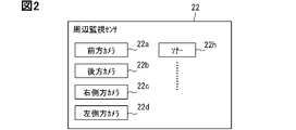
- FIG. It is a block diagram which shows an example of the periphery monitoring sensor with which an in-vehicle system is provided.
- FIG. 5 is a diagram showing an example of a combination of display areas selectable by the HCU as information display destinations. It is a functional block diagram of HCU. It is a figure which shows an example of an alerting image.
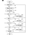
- 4 is a flowchart for explaining an example of the operation of the HCU when getting off the vehicle;
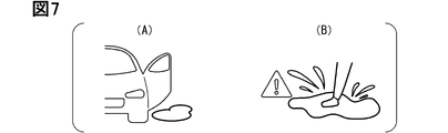
- FIG. 10 is a diagram showing an example of a summary image that notifies the existence of a puddle; It is a figure which shows an example of the outline
- FIG. 10 is a diagram showing an example of a summary image that notifies a mobile object approaching from behind; 4 is a flowchart for explaining an example of the operation of the HCU when getting off the vehicle; It is a figure which shows an example of the outline
- FIG. 10 is a diagram showing an example of a summary image that notifies a mobile object approaching from behind; 4 is a flowchart for explaining an example of the operation of the HCU when getting off the vehicle; It is a figure which shows an example of the outline
- FIG. 10 is a flowchart for explaining an example of HCU operation when entering a parking lot;
- FIG. 4 is a flowchart for explaining an example of the operation of the HCU when starting the vehicle;
- 4 is a flowchart for explaining an example of HCU operation based on entry into a predetermined permitted area;
- FIG. 10 is a flowchart for explaining an example of HCU operation associated with approaching a destination;
- FIG. It is a figure which shows the modification of a door display. It is a figure which shows an example of the variation of a display area.
- FIG. 1 is a diagram showing an example of a schematic configuration of an HCU 1 as an information presentation device according to the present disclosure.
- the HCU 1 is a device that controls the operation of an HMI (Human Machine Interface), and stands for HMI Control Unit.
- HMI Human Machine Interface
- the present disclosure can also be applied to information presentation control for passengers in front passenger seats and passengers in rear seats.
- the information presentation target according to the present disclosure is applied to a passenger in a front passenger seat, etc.
- the following description can be appropriately changed and implemented so as to correspond to the information presentation target seat.
- the driver's seat is provided on the right side of the vehicle will be exemplified below. Therefore, the right side of the vehicle corresponds to the seat side direction.
- the present disclosure may be applied to vehicles in which the driver's seat is provided on the left side. In that case, the left side of the vehicle corresponds to the seat side direction.
- the vehicle equipped with HCU1 is also referred to as own vehicle/equipped vehicle.
- directions of front and rear, left and right, and up and down are defined with reference to the host vehicle.
- the longitudinal direction corresponds to the longitudinal direction of the vehicle.
- the left-right direction corresponds to the width direction of the host vehicle.
- the vertical direction corresponds to the height direction of the vehicle. From another point of view, the vertical direction corresponds to a direction perpendicular to a plane parallel to the front-rear direction and the left-right direction.
- the HCU 1 is used by being connected to various in-vehicle devices.
- the HCU 1 is connected to various in-vehicle sensors 21, a surrounding monitoring sensor 22, an in-vehicle camera 23, an exterior microphone 24, an input device 25, a V2X in-vehicle device 26, an automatic parking ECU 27, and a navigation ECU 28.
- HCU 1 is also connected to meter display 31 , center display 32 , HUD 33 , door display 34 , vehicle interior speaker 35 , vehicle exterior speaker 36 , road surface light 37 , air conditioner 38 , and interior lighting device 39 .
- HUD as a member name means a head-up display (Head-Up Display).
- V2X is an abbreviation for Vehicle to X (everything/something), and refers to communication technology that connects cars to various things.
- the "V” in V2X can refer to a car as the own vehicle, and the "X” can refer to various entities other than the own vehicle, such as pedestrians, other vehicles, road facilities, networks, and servers.
- the HCU 1 and various in-vehicle devices may be connected via a dedicated line or via an in-vehicle network. Further, an ECU may be interposed between the HCU 1 and the in-vehicle device. For convenience, the configuration including the in-vehicle device connected to HCU1 and HCU1 is described as in-vehicle system Sys.
- the in-vehicle sensor 21 is a sensor that detects physical state quantities that indicate the state of the vehicle and the content of the driver's driving operation.
- Examples of the in-vehicle sensor 21 include a vehicle speed sensor, an acceleration sensor, a steering angle sensor, a shift position sensor, an accelerator pedal sensor, a brake pedal sensor, and the like.
- the accelerator pedal sensor is a sensor that detects the depression amount/depression force of the accelerator pedal.
- the brake pedal sensor is a sensor that detects the depression amount/depression force of the brake pedal.
- In-vehicle sensors also include sensors/switches that detect the operating state of the parking brake and the power state of the vehicle.
- the in-vehicle sensor 21 also includes a seat belt sensor for the driver's seat and a seating sensor.
- the seat belt sensor is a sensor that detects the wearing state of the seat belt.
- a seat sensor is a sensor that detects that a person is seated, and is provided for each seat, for example.
- the seating sensors can be, for example, pressure sensors embedded in the seating surface of each seat.
- the concept of the in-vehicle sensor 21 also includes an inner door handle sensor and an in-vehicle microphone.
- An inner door handle is a door handle provided inside the door for the driver's seat.
- the inner door handle sensor is a sensor that detects that the driver is gripping the inner door handle, more preferably gripping force (gripping pressure).
- the inner door handle sensor can be a capacitive or pressure sensitive touch sensor provided on the inner door handle.
- the inner door handle sensor may be an infrared sensor whose detection range is very close to the inner door handle (for example, within 5 cm).
- the in-vehicle microphone is a microphone that acquires the voice spoken by the driver, and is provided near the driver's seat.
- the surroundings monitoring sensor 22 is a device that collects information about the external environment around the vehicle.
- a camera millimeter wave radar, LiDAR (Light Detection and Ranging/Laser Imaging Detection and Ranging), sonar, or the like can be employed.
- the millimeter-wave radar transmits millimeter waves or quasi-millimeter waves in a predetermined direction, and analyzes the reception data of the reflected waves returned by the transmitted waves reflected by the object.
- It is a device that detects the relative position and relative velocity of LiDAR is a device that generates three-dimensional point cloud data indicating the positions of reflection points for each detection direction by irradiating laser light.
- a sonar is a sensor that detects obstacles by transmitting ultrasonic waves as search waves.
- the in-vehicle system Sys includes a front camera 22a, a rear camera 22b, a right side camera 22c, and a left side camera 22d as perimeter monitoring sensors 22, as shown in FIG.
- the front camera 22a, the rear camera 22b, the right side camera 22c, and the left side camera 22d can be called peripheral monitoring cameras.
- the in-vehicle system Sys includes a plurality of sonars 22h as surrounding monitoring sensors 22 .
- the front camera 22a is a camera that captures an image of the front of the vehicle with a predetermined angle of view.
- the front camera 22a is arranged, for example, at the upper end of the windshield on the interior side of the vehicle or at the front grill.
- the rear camera 22b is a camera that captures an image of the rear of the vehicle with a predetermined angle of view.
- the rear camera 22b is arranged at a predetermined position on the rear surface of the vehicle body, such as near the rear license plate or near the rear window.
- the term “near” a certain member refers to a range within, for example, 30 cm from the member.
- near the license plate refers to a range within 30 cm from the license plate.
- the right side camera 22c and the left side camera 22d are cameras for capturing an image of the side of the vehicle at a predetermined angle of view, and are arranged, for example, in the side mirrors, at predetermined positions on the left and right sides of the body, and near the base of the A pillar. .
- the right side camera 22c corresponds to an exterior camera whose imaging range includes the vicinity of the door for the driver's seat.
- the right side camera 22c and the left side camera 22d are simply referred to as side cameras.
- Multiple sonar 22h are distributed in multiple locations such as front/rear bumpers, fenders, and door panels. For example, four sonars 22h are distributed from the right corner to the left corner of the front bumper. Four sonars 22h are distributed from the right corner to the left corner of the rear bumper of the vehicle. Such an arrangement mode of the sonar 22h enables the in-vehicle system Sys to detect an object existing in front of or behind the own vehicle. Some sonars 22h may be attached to side sills, fenders, and door panels so as to emit ultrasonic waves toward the sides of the vehicle.
- the in-vehicle system Sys may be equipped with millimeter wave radar and LiDAR. Since the sonar 22h, millimeter wave radar, and LiDAR are sensors capable of acquiring distance information from an object, they can be called ranging sensors.
- the in-vehicle system Sys may include an underfloor sonar, which is a sonar whose detection range is below the bottom of the vehicle body, that is, under the floor, or an underfloor camera that captures an image of the underfloor. Underfloor cameras can also be included in perimeter surveillance cameras.
- the various surroundings monitoring sensors 22 described above detect a predetermined object to be detected and specify the relative position of the detected object with respect to the own vehicle. Then, detection result data indicating the position, type, etc. of the detected object is sequentially provided to the HCU 1 and the automatic parking ECU 27 (hereinafter referred to as the HCU 1 and the like).
- the HCU 1 or the automatic parking ECU 27 may have the function of recognizing an object based on image data. Image data also includes video signals.
- the objects to be detected here are, for example, pedestrians, animals other than humans, other vehicles, and structures installed along the road.
- Other vehicles include bicycles, motorized bicycles and motorcycles.
- the structures installed along the road include, for example, guardrails, curbs, trees, utility poles, road signs, and traffic lights.
- road markings such as lane markings and fallen objects on the road are also registered as objects to be detected by the perimeter monitoring camera as a more preferable aspect. Pavement markings may also include parking lot numbers, etc. that are printed on parking lots.
- a peripheral monitoring camera such as the front camera 22a may output a video signal to the HCU 1 or the like.
- the position of the detected object is expressed, for example, in a vehicle coordinate system, which is a three-dimensional coordinate system with a predetermined reference point of the own vehicle as the origin.
- the X-axis forming the vehicle coordinate system is parallel to the left-right direction of the vehicle, and is set so that the right direction, for example, is the positive direction.
- the Y-axis is parallel to the longitudinal direction of the vehicle, and is set so that the forward direction of the vehicle is the positive direction.
- the Z axis is set to correspond to the vehicle height direction.
- the vehicle coordinate system may be a two-dimensional coordinate system omitting the Z-axis.
- the in-vehicle camera 23 is a camera (hereinafter referred to as an in-vehicle camera) that is arranged to capture an image of an occupant in the driver's seat.
- the in-vehicle camera 23 may be arranged on the ceiling of the vehicle interior, such as an overhead console, so as to be able to capture an image of the entire vehicle interior.
- a driver status monitor can be adopted as the in-vehicle camera 23, for example.
- the DSM is a device that detects the line-of-sight direction and behavior of the driver based on the driver's facial image.
- a DSM includes, for example, a near-infrared light source, a near-infrared camera, and a control module for controlling them.
- the DSM is installed, for example, on the upper surface of the steering column or the upper surface of the instrument panel, with the near-infrared camera facing the direction in which the headrest of the driver's seat exists.
- the camera that constitutes the DSM may be a visible light camera.
- the in-vehicle camera 23 outputs the driver state information extracted from the driver's image to the HCU 1 .
- the driver status information includes, for example, the orientation of the driver's face and line of sight.
- the HCU 1 may have the function of detecting the line-of-sight direction of the driver based on the driver's image analysis.
- the in-vehicle camera 23 should just be comprised so that an output of a driver's face image to HCU1 is possible.
- the vehicle exterior microphone 24 is a microphone arranged on the exterior of the vehicle.
- the outside microphone 24 is installed at the door for the driver's seat or around the door, for example, the A pillar, so as to easily acquire the voice of the driver who is about to get into the vehicle.
- the outside microphone 24 converts an external sound into an electric signal and outputs the electric signal to the HCU 1 .
- the input device 25 is an operation member for receiving the driver's instructions to the in-vehicle system Sys.
- the input device 25 may be a mechanical switch (so-called steer switch) provided on the spoke portion of the steering wheel, or may be a voice input device that recognizes the content of the driver's speech.
- the input device 25 may be a touch panel laminated on a display panel of a display provided in an instrument panel, such as the center display 32, for example.
- the input device 25 outputs to the HCU 1 an electrical signal corresponding to an operation performed by the user on the device as a user operation signal.
- the user operation signal includes information indicating the details of the user's operation.
- the V2X vehicle-mounted device 26 is a communication module for wireless communication between the vehicle and other devices.
- the V2X vehicle-mounted device 26 is configured to be able to implement cellular communication, which is wireless communication conforming to, for example, LTE (Long Term Evolution), 4G, 5G, and the like.
- the V2X vehicle-mounted device 26 acquires weather information such as the probability of rain for each hour from an external server, a roadside device, or the like.
- the V2X vehicle-mounted device 26 may be configured to be capable of performing short-range communication, which is communication based on Wi-Fi (registered trademark) or Bluetooth (registered trademark).
- the V2X vehicle-mounted device 26 may be configured to be capable of performing communication conforming to a short-range communication standard for vehicles, such as DSRC (Dedicated Short Range Communications).
- the V2X vehicle-mounted device 26 includes an antenna that can transmit and receive radio waves of frequencies used in various communication standards, an IC that performs modulation and demodulation, and the like.
- the automatic parking ECU 27 is an ECU that automatically parks the vehicle at the target parking position based on information such as the image of the surroundings of the vehicle and the position of the detected object input from the surroundings monitoring sensor 22 .
- the automatic parking ECU 27 automatically controls the wheel angle and traveling speed from the point at which the driver instructs to execute automatic parking to the target parking position, and autonomously moves the vehicle to the target parking position.
- the automatic parking here also includes a mode in which a so-called driver parks the vehicle autonomously by remote control using a device such as a smartphone that is linked to the vehicle.
- the automatic parking ECU 27 performs control to autonomously drive the vehicle toward the target parking position on condition that the user as the driver presses a predetermined automatic parking button displayed on the smartphone. may be configured to
- the automatic parking ECU 27 is triggered by an instruction signal from a mobile terminal linked to the own vehicle, powers on the own vehicle in the parked state, and autonomously moves to a position designated by the driver or near the driver. It may be configured to be able to execute automatic garage leaving control to make the vehicle travel.
- the automatic parking ECU 27 may be configured to be able to execute automatic parking control and automatic garage leaving control, for example, on condition that the driver exists within a predetermined distance from the own vehicle.
- the automatic parking ECU 27 may perform automatic parking and automatic exit in cooperation with the infrastructure installed in the parking lot.
- the navigation ECU 28 is a device that displays a map image according to the current position of the vehicle and provides route guidance.
- the navigation ECU 28 has, for example, a map database and a GNSS (Global Navigation Satellite System) receiver.
- a GNSS receiver is a device that sequentially detects the current position of the GNSS receiver (for example, every 100 milliseconds) by receiving positioning signals from a plurality of positioning satellites.
- the map data used by the navigation ECU 28 includes location information of parking lots associated with facilities.
- the navigation ECU 28 outputs position information of the own vehicle and surrounding map information to the HCU 1 . Further, as a more preferable aspect, the navigation ECU 28 outputs to the HCU 1 a signal indicating that the vehicle has entered a parking lot attached to the facility, based on the location information of the vehicle and the map data.
- the meter display 31 is a display arranged in an area located in front of the driver's seat on the instrument panel.
- a liquid crystal display, an organic EL (Electro-Luminescence) display, or the like can be used as the display.
- the center display 32 is a display arranged near the center in the vehicle width direction on the instrument panel.
- the center display 32 is arranged near the shift lever/shift button.
- the center display 32 may be a display arranged on the center console.
- the HUD 33 is a device that displays a virtual image that can be perceived by the driver by projecting image light onto a predetermined area of the windshield based on control signals and image data input from the HCU 1, navigation ECU, and the like.
- the HUD 33 displays an image superimposed on the scenery in front of the vehicle.
- 33a in FIG. 3 indicates a display area (projection area) of an image by the HUD 33. As shown in FIG.
- the door display 34 is a display provided on the door for the driver's seat.
- the door display 34 is arranged along the lower edge of the window frame of the driver's seat door trim, as shown in FIG.
- the door display 34 may have a curved display surface along the shape of the door trim.
- a light transmissive skin display can be adopted.
- a light-transmissive skin display is a display that has an artificial skin that allows light to pass through.
- the door display 34 can be implemented using an organic EL display, a liquid crystal panel, or the like.
- the size of the display area of the door display 34 is preferably set to 3 cm long and 5 cm wide or more so that various texts or summary images can be displayed.
- the door display 34 is set to approximately 5 cm long and 20 cm wide.
- the vertical and horizontal directions are concepts for explaining the size of the display area of the door display 34, and the vertical direction corresponds to the height direction or the vehicle width direction of the vehicle, and the horizontal direction corresponds to the longitudinal direction of the vehicle.
- the display screen of the door display 34 corresponds to the door display area.
- Each of the meter display 31, the center display 32, the HUD 33, and the door display 34 displays an image according to the signal input from the HCU1.
- the meter display 31 and the HUD 33 correspond to devices forming a front display area, which is a display area located in front of the driver's seat.
- the center display 32 corresponds to a device that provides a passenger seat side display area, which is a display area positioned closer to the passenger seat than the front display area.
- the HCU 1 of the present disclosure is configured to be able to selectively adopt a front display area, a front passenger seat side display area, and a door display area as display destinations of information images.
- Each display area is formed by a different device, and is distributed so as to be separated from each other by 5 cm or more in the actual space inside the vehicle.
- the in-vehicle speaker 35 is a speaker provided inside the vehicle.
- the in-vehicle speaker 35 is provided, for example, on an instrument panel.
- the vehicle exterior speaker 36 is a speaker provided on the exterior of the vehicle.
- the outside speaker 36 is arranged at the bottom of the vehicle body or near the door for the driver's seat.
- the outside speaker 36 is a speaker mainly for communicating with a person in the vicinity of the vehicle.
- the vehicle exterior speaker 36 is also used for the driver in the vehicle to speak to an animal such as a cat that has entered under the vehicle body, or to make a sound for moving the animal.
- the in-vehicle speaker 35 and the out-of-vehicle speaker 36 each convert the electrical signal input from the HCU 1 into sound and output the sound.
- the expression "sound" includes voice and music.
- the road surface light 37 is a lighting device that illuminates the road surface near the door for the driver's seat.
- the road surface light 37 is provided, for example, in the side mirror on the side of the driver's seat, in the lower end of the door for the driver's seat, or in the vicinity of the side sill on the side of the driver's seat.
- the road surface light 37 includes light source elements such as LEDs.
- the road surface light 37 illuminates a predetermined area of the road surface with color and brightness according to the instruction signal from the HCU 1 .
- the air conditioner 38 is a device that outputs conditioned air, which is air whose temperature has been adjusted according to the set temperature, from an outlet provided in the vehicle.
- the air conditioner 38 is configured to perform cooling and heating by a heat pump cycle capable of performing heating and cooling with one refrigerant circuit, for example.
- the air conditioner 38 has a function as an aroma shooter that injects a preset fragrance into the passenger compartment.
- the air conditioner 38 is configured to be capable of outputting scents such as lemon and mint, which can be expected to have a refreshing effect, into the passenger compartment.
- the in-vehicle lighting device 39 is a lighting device arranged in the vehicle interior.
- the in-vehicle lighting device 39 can be a lighting device in which a plurality of light sources are arranged in a line along joints or edges of parts, for example, in door trims and instrument panels.
- the in-vehicle lighting device 39 is configured, for example, so that light leaks out from joints of interior parts.
- the in-vehicle lighting device 39 may be configured as indirect lighting that indirectly illuminates the feet and the like.
- the in-vehicle lighting device 39 may be configured as a so-called ambient light.
- the HCU 1 is a computer that comprehensively controls presentation of information to the driver using various displays/projectors.
- the HCU 1 is configured as a computer including a processor 11, a RAM (Random Access Memory) 12, a storage 13, a communication interface 14 (I/O in the drawing), and a bus line connecting these components.
- the processor 11 is an arithmetic core such as a CPU (Central Processing Unit).
- the processor 11 accesses the RAM 12 to perform various processes.
- RAM 12 is a volatile memory.
- a communication interface 14 is a circuit for the HCU 1 to communicate with other devices.
- the communication interface 14 may be implemented using an analog circuit element, an IC, or the like.
- the storage 13 is configured to include a non-volatile storage medium such as flash memory.
- the storage 13 stores a display control program, which is a program for causing the computer to function as the HCU1. Execution of the display control program by the processor 11 corresponds to execution of a display control method, which is a method corresponding to the display control program.
- a display control method which is a method corresponding to the display control program.
- data indicating the driver's schedule, personality, etc. are registered.
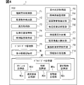
- the HCU 1 provides each functional unit shown in FIG. 4 by executing the display control program stored in the storage 13 by the processor 11 . That is, the HCU 1 includes a line-of-sight direction acquisition section F1, a vehicle exit motion detection section F2, a wind force acquisition section F3, a parking position acquisition section F4, a driver data management section F5, and a vehicle exterior situation acquisition section F6. The HCU 1 also includes a waiting necessity determination unit F7, a parking lot entry detection unit F8, an adjacent parking probability acquisition unit F9, and an information presentation processing unit F10.
- the parking position acquisition section F4 includes a candidate section acquisition section F41 as a sub-function section.
- the vehicle exterior condition acquisition unit F6 includes, as sub-function units, an exit road surface monitoring unit F61 and an open door obstacle detection unit F62. Data acquired or generated by each functional unit is temporarily stored in a memory such as the RAM 12 and used by other functional units as a reference.
- the HCU 1 also includes a display information storage unit M1 and a driver data storage unit M2.
- the display information storage unit M1 stores display data for each predetermined event to be notified.
- a notification target event is an event occurring outside the vehicle that should be notified to the driver, and includes, for example, an event that may impair the driver's safety or convenience.
- the notifiable events related to safety correspond to events targeted for alerting/warning.
- the content of the display data is, for example, an outline of the event to be notified, or a recommended action indicating the action pattern that the driver should take in response to the event.
- the display data may be text indicating an overview or recommended action, or may be an overview image that schematically indicates an overview or recommended action.
- a summary image is an image that includes image elements that indicate the contents of the attention target and the contents of the proposal.
- a summary image is different from a simple reminder image that does not contain specific content of attention targets.
- the alert image refers to an icon image combining an exclamation mark/exclamation mark and a figure such as a circle or a triangle, as shown in FIGS. 5A and 5B.
- the alert image corresponds to an image that does not make it clear what the driver should pay attention to or what the driver should do.
- the overview image is an image including an image element indicating an attention target or a coping method (recommended action). Details of the recommended action and the summary image for each event to be alerted will be described separately later.
- the driver data storage unit M2 stores personal data such as the driver's schedule.
- the driver data storage unit M2 includes, as more detailed elements, a schedule storage unit M2a, a personality storage unit M2b, a pet animal storage unit M2c, a normal opening storage unit M2d, and a proficiency storage unit M2e.
- the schedule storage unit M2a is a storage area for driver schedule data.
- the personality storage unit M2b is a storage area for data indicating the personality of the driver, such as whether the driver is neat, impatient, methodical, and rough.
- the favorite animal storage unit M2c is a storage area for data indicating the animal that the driver likes.
- the pet-loving memory unit M2c may be integrated with the personality memory unit M2b.
- the normal opening degree storage unit M2d is a storage area for data indicating the normal opening degree, which is the daily opening degree of the door.
- the normal opening may be learned based on the driver's vehicle usage history, or may be registered by the driver. For example, the normal opening may be determined based on the door opening/closing operation performed by the driver in the registration mode. The normal opening can be represented by an angle or the like.
- the normal opening storage unit M2d may store the speed at which the door is opened, etc. in association with the normal opening.
- the proficiency level storage unit M2e is a storage area for data indicating the driving skill level, in other words, the driving proficiency level.
- the degree of driving skill may be determined automatically based on the frequency of sudden braking or steering, the number of times of turning during parking, or may be manually input by the driver.
- the display information storage unit M1 and the driver data storage unit M2 can be implemented using storage areas provided in the storage 13 .
- the driver data storage unit M2 may be implemented using part of the storage area of the RAM 12 .
- the line-of-sight direction acquisition unit F1 acquires the driver's line-of-sight direction, face orientation, and head position based on the output signal of the in-vehicle camera 23 .
- the in-vehicle camera 23 recognizes the line-of-sight direction of the driver and outputs the recognition result, but the present invention is not limited to this.
- the line-of-sight direction acquisition unit F1 may analyze the image captured by the in-vehicle camera 23 to identify the line-of-sight direction and the like.
- the getting-off motion detection unit F2 is configured to detect the driver's getting-off motion.
- the getting off operation corresponds to a preliminary operation for opening the door and getting off the vehicle.
- the getting-off motion can be read as a getting-off preliminary motion.
- Detecting the getting-off operation corresponds to determining that the driver is about to open the door.
- Dismounting actions include, for example, the act of setting the shift lever to the parking position, turning off the driving power supply, setting the parking brake on, removing the seat belt, and placing the hand on the inner door handle. and unlocking the door.
- the driver's turning his body toward the door or uttering a get-off phrase which is a phrase suggesting arrival at the destination, can also be used as a get-off motion.
- the get-off phrase includes a phrase indicating arrival at the destination such as "I've arrived” and a phrase such as "Get off” that prompts fellow passengers to get off.
- Various actions can be specified based on the output signals of various on-vehicle sensors/ECUs such as a shift position sensor, power switch, image of the in-vehicle camera 23, seat belt sensor, door lock sensor, and in-vehicle microphone.
- the getting-off operation detection unit F2 may determine that the driver is going to get off the vehicle by combining some of the above actions.
- the wind force acquisition unit F3 is configured to acquire the strength of the wind outside the vehicle.
- wind speed is used as an index indicating wind strength (that is, wind power), but the present invention is not limited to this.
- the strength of the wind may be expressed in multiple stages such as levels 1 to 3, for example.
- the wind force acquisition unit F3 cooperates with, for example, the V2X vehicle-mounted device 26 and acquires the wind speed at the current position from a server that handles weather information.
- the wind force acquisition unit F3 may acquire the wind speed based on the magnitude of the wind noise acquired by the external microphone 24 . Wind noise is detected as noise by the external microphone 24, and the noise level tends to increase as the wind becomes stronger. Therefore, the wind force acquisition unit F3 may determine the wind speed based on the noise level output by the external microphone 24 .
- the parking position acquisition unit F4 is configured to acquire the target parking position, which is the target position for parking by the automatic parking ECU 27 or the driver. For example, the parking position acquisition unit F4 automatically determines the target parking position based on the result of recognition of the outside world by the surroundings monitoring sensor 22 .
- the parking position acquisition unit F4 may determine the target parking position based on the driver's operation signal output by the input device 25 in cooperation with the HCU1. Specifically, the target parking position is determined by the HCU 1 presenting parking space candidates to the driver based on the results of recognition of the external environment by the surroundings monitoring sensor 22, and finally determining the target parking position by the driver's operation on the input device 25. Also good.
- the target parking position may be determined based on vacant parking space information received by wireless communication from a parking lot device, which is infrastructure equipment provided in the parking lot.
- a parking lot device corresponds to a kind of roadside unit.
- the target parking position corresponds in one aspect to a target point for the automatic parking ECU 27 to perform automatic parking or parking assistance.
- the target parking position may be a target point when the driver manually parks.
- the candidate section acquisition unit F41 acquires position information on the presence of a candidate section, which is a section in which vehicles can be parked, in a parallel parking lot, which is a parking lot provided with a plurality of parking sections for parallel parking of a plurality of vehicles. do.
- the facility-associated parking lot described above may also correspond to the parallel parking lot depending on the arrangement of the parking lots.
- the information of the candidate section may be generated based on the detection result of the perimeter monitoring sensor 22, or may be obtained through wireless communication with the parking lot device.
- a parking lot device for example, distributes information about empty spaces in a parking lot.
- the parking apparatus may distribute data indicating the probability of use for each section. The use probability for each section is statistically determined from the past use history.
- the candidate block acquisition unit F41 can identify an empty area in a specific time zone such as noon.
- the driver data management unit F5 acquires the driver's personal information and stores it in the driver data storage unit M2.
- the personal information includes, for example, a part or all of the driver's schedule, personality, favorite animal, normal opening, level of driving skill, and the like.
- the driver's schedule can be acquired from an external server that holds driver information or from the driver's smartphone in cooperation with the V2X vehicle-mounted device 26 .
- the driver's personality and normal opening may be learned based on the driver's vehicle usage history.
- the usage history can include a driving history, which is a history of driving operations. If the own vehicle is a vehicle provided for a sharing service, the driver data management unit F5 obtains the information of the next user from a predetermined external server based on the change of the user, and stores the driver data. Rewrite the data stored in the storage unit M2.
- the vehicle-exterior situation acquisition unit F6 recognizes the situation outside the vehicle, in other words, the surrounding environment, based on the output signal of the surroundings monitoring sensor and the data received by the V2X vehicle-mounted device 26 .
- the vehicle exterior situation acquisition unit F6 recognizes the surrounding environment based on the image of the surrounding monitoring camera.
- the surrounding environment here includes the positions and moving speeds of other moving bodies existing around the own vehicle, the shapes and sizes of surrounding objects, and the like.
- the vehicle exterior condition acquisition unit F6 also acquires road markings such as lane markings added to the road surface and road surface conditions based on the image data of the peripheral monitoring camera.
- the vehicle exterior condition acquisition unit F6 may acquire detection results from each of the plurality of surroundings monitoring sensors 22 and combine them to recognize the position and type of an object existing around the vehicle.
- the external situation acquisition unit F6 may specify the surrounding environment using other vehicle information received by the V2X vehicle-mounted device 26 from other vehicles, dynamic map information received from roadside units through road-to-vehicle communication, and the like.
- the dynamic map information indicates the position, movement speed, and the like of the moving object.
- the vehicle exterior situation acquisition unit F6 dynamically generates a three-dimensional map of the surroundings of the vehicle and the vicinity of the target parking point based on the detection results of the surroundings monitoring sensor 22.
- the three-dimensional map corresponds to map data obtained by mapping detected objects of the perimeter monitoring sensor 22 in a virtual space corresponding to the vehicle coordinate system.
- the vehicle exterior condition acquisition unit F6 detects notification target events outside the vehicle interior based on the output data of the surroundings monitoring sensor 22 and the like.
- Notification target events can include, for example, other moving bodies approaching the own vehicle, three-dimensional objects that are likely to come into contact with the own vehicle, unevenness of the road surface that can affect the posture of the vehicle, steps, and the like.
- the alighting road surface monitoring unit F61 and the door opening obstacle detection unit F62 are functional elements that detect notification target events according to the scene.
- the getting-off road surface monitoring unit F61 detects an event to be notified at the getting-off spot, which is a road surface area where the driver can land when getting off, based on the image of the peripheral monitoring camera such as the side camera on the driver's seat side (that is, the right side camera 22c). exists.
- the drop-off spot corresponds to a road surface area within a predetermined distance (for example, 1 m) from the door for the driver's seat.
- Notification target events that can occur at the drop-off spot include puddles, recesses such as gutters, three-dimensional objects such as steps, and garbage. For example, low fences with a height of less than 0.5 m, road cones, large stones, etc. can be included in notification target events at the drop-off spot.
- a three-dimensional object whose height is less than a predetermined threshold (for example, 0.2 m) and which is lower than the lower edge of the door or the bottom of the vehicle body is also referred to as a low-height three-dimensional object.
- a low-height three-dimensional object corresponds to a three-dimensional object that does not come into contact with a door that is opened and closed.
- HCU 1 detects a notification target event such as a puddle based on the camera image as an example here.
- the detection (recognition) of puddles and the like may be performed by a peripheral monitoring camera or another ECU.
- the alighting road surface monitoring unit F61 starts searching for an obstacle for opening the door, for example, when the vehicle speed becomes equal to or less than a predetermined monitoring start threshold.
- the monitoring start threshold can be, for example, 0 km/h, 5 km/h, 10 km/h, or the like.
- the door-opening obstacle detection unit F62 is based on the image captured by the side camera on the driver's side and the detection result of the sonar 22h. Determines whether or not there is a three-dimensional object that may come into contact with A three-dimensional object that may come into contact with the driver's seat door is also referred to herein as an obstacle for opening the door.
- Door-opening obstacles are, for example, other vehicles, utility poles, walls, and the like.
- the door opening obstacle detection section F62 detects that there is an obstacle for opening the door within 0.75 m from the driver's seat door based on the output signal of the sensor. Note that obstacles that interfere with door opening (door opening) are not limited to stationary objects. Pedestrians and the like existing within the movable range of the driver's door can also be included in the door opening obstacles.
- the door-opening obstacle detection unit F62 also starts searching for the door-opening obstacle, for example, when the vehicle speed becomes equal to or less than a predetermined monitoring start threshold. Further, when the parking position acquisition unit F4 specifies the target parking point, the opening obstacle detection unit F62 determines whether or not there is an obstacle for opening the door based on the detection result of the surrounding monitoring sensor 22 for the vicinity of the target parking point. judge. That is, the door-opening obstacle detection unit F62 determines whether the target parking position is in a narrow environment that hinders the opening and closing of the driver's seat door at a stage a predetermined distance before the target parking position (that is, in advance). The door-opening obstacle detection part F62 outputs the determination result concerning the presence or absence of the door-opening obstacle to the information presentation processing part F10.
- the pre-start surroundings confirmation unit F63 detects animals or pedestrians existing in the vicinity of the vehicle based on the output signal of the surroundings monitoring sensor 22 that is driven when the power supply for running is turned on.
- the near area here is an area within 0.3 m from the vehicle body, and includes around tires and around bumpers.
- the neighborhood area can include the underfloor.
- the pre-start surroundings confirmation unit F63 compares an image outside the vehicle captured by a camera for monitoring the surroundings when the vehicle is parked with an image outside the vehicle that is acquired after the power source for running is turned on, to determine whether a cat or the like exists in the vicinity area. Detect animals and pedestrians (children).
- the pre-start surrounding confirmation part F63 may be configured to detect a small animal such as a cat that has entered under the vehicle body based on the detection results of the underfloor camera or underfloor sonar.
- the vehicle exterior situation acquisition unit F6 determines whether or not there is another moving object scheduled to pass on the side of the vehicle on the driver's seat side.
- Other moving bodies scheduled to pass on the side of the vehicle on the driver's seat side correspond to notification objects as notification target events.
- the vehicle-outside situation acquisition unit F6 extracts moving objects (hereinafter referred to as approaching objects) in which other vehicles or pedestrians are moving toward the own vehicle from behind or in front of the own vehicle. Then, the vehicle exterior situation acquisition unit F6 passes within a predetermined distance (for example, 1.5 m) from the driver's door within a predetermined time period, such as 10 seconds, based on the moving speed, moving direction, and position information of the approaching object.
- a predetermined distance for example, 1.5 m
- a predetermined time period such as 10 seconds
- the outside-vehicle situation acquisition unit F6 detects an approaching object that satisfies the above conditions as a notification target.
- the vehicle exterior situation acquisition unit F6 notifies the detected approaching object. You may exclude it from a target object.
- the vehicle exterior condition acquisition unit F6 determines whether or not there is a strong wind outside the vehicle based on the wind speed acquired by the wind force acquisition unit F3, and outputs the determination result to the information presentation processing unit F10.
- the outside-vehicle situation acquisition unit F6 sequentially acquires surrounding environment information, which is information about the surrounding environment, based on, for example, that the vehicle speed is equal to or less than the monitoring start threshold. Acquisition here also includes generation/detection by internal computation.
- a state in which the vehicle speed is equal to or lower than the monitoring start threshold includes a state in which the vehicle is stopped.
- the waiting necessity determination unit F7 determines whether or not it is recommended to open the door and wait based on the surrounding environment information acquired by the vehicle exterior situation acquisition unit F6.
- the door open standby recommended state is a state in which the driver should wait for the door to open. For example, when it is recommended to wait for the door to open, there may be another moving object that is scheduled to pass near the driver's door, or if a person is coming from a parallel parked vehicle that is parked alongside the driver's seat. For example, when you are about to get off.
- the standby necessity determination unit F7 determines that the open door standby recommended state applies when the vehicle exterior situation acquisition unit F6 detects an approaching object scheduled to pass near the driver's seat door.
- the waiting necessity determination unit F7 detects that a person is about to leave the parallel parked vehicle, for example, that the front passenger door is moving, by analyzing the image of the side camera on the driver's seat side. If it is, it is determined that it corresponds to the open door standby recommended situation.
- the parking lot entry detection unit F8 Based on the signal from the navigation ECU 28, the parking lot entry detection unit F8 detects that the vehicle has entered the parking lot attached to the facility. Whether or not the vehicle has entered the parking lot attached to the facility can be specified by, for example, matching the vehicle position information with the map data.
- the navigation ECU 28 or the parking lot entry detector F8 may determine whether the vehicle has entered the parking lot attached to the facility based on the vehicle position information and the map data.
- the functional arrangement in the in-vehicle system Sys can be changed as appropriate.
- the parking lot entry detection unit F8 may detect entry into the facility-attached parking lot based on the reception of a radio signal from the parking lot device. Further, it may be detected that the vehicle has entered the parking lot attached to the facility based on the detection of a plurality of parking lane lines by analyzing the image of the peripheral monitoring camera.
- the adjacent parking probability acquisition unit F9 detects that the parking lot entry detection unit F8 has entered the facility-attached parking lot, and the candidate block acquisition unit F41 has acquired the candidate block, and calculates the adjacent parking probability. to get The adjacent parking probability is the probability that another vehicle will park in the adjacent parking space on the driver's seat side among the parking spaces adjacent to the candidate space.
- the adjacent parking probability can be calculated based on data indicating the probability of use for each section provided by wireless communication from the parking lot device. Also, the adjacent parking probability may be calculated based on the parking history data when the own vehicle was parked in the candidate section in the past.
- the parking history data is data in which the location information of the parked section, the parking time, the start time, and whether or not another vehicle was parked in the adjacent section on the driver's seat side at the start. It can be specified based on the detection result of the perimeter monitoring sensor 22 whether or not another vehicle was present in the adjacent section when the vehicle started.
- the information presentation processing unit F10 positions the image indicating the content of the event to be notified detected by the external situation acquisition unit F6 or the recommended action corresponding to the event in the line-of-sight direction of the driver acquired by the line-of-sight direction acquisition unit F1. Display in the display area. Note that the concept of image display also includes text display. Display data such as a recommended action corresponding to the detected event is obtained by referring to the display information storage unit M1. The display area located in the line-of-sight direction can be understood as the display closest to the line-of-sight direction.
- the information presentation processing unit F10 corresponds to the display processing unit.
- the exiting operation detection unit F2 detects the exiting operation
- the detected notification target is displayed on the door display 34.
- the details of the notification target event detected or the recommended action is displayed on the center display 32 .
- the content of the detected event to be notified or the recommended action is displayed on the meter display 31 or the display area 33a of the HUD 33.
- the information presentation processing unit F10 changes the information display location according to the line-of-sight direction of the driver.
- information is displayed in the display area positioned in the line of sight when the driving power source is switched from off to on, or when the shift position is switched from the parking position to the driving position. That is, in the start scene, the display area/display corresponding to the line-of-sight direction at the time when the predetermined start operation is detected based on the output signal of the in-vehicle sensor 21 is adopted as the display destination of various information.
- the display area corresponding to the line-of-sight direction refers to the display area arranged at a position within the driver's stable fixation field.
- the stable fixation field is a range in which the focus is quickly stabilized even when the fixation point is moved, and is an elliptical range of ⁇ 80 degrees in the horizontal direction and ⁇ 60 degrees in the vertical direction.
- the display area closest to the direction of the center of the line of sight is selected as the information output destination.
- the information presentation processing unit F10 preferentially selects a display area within the driver's effective field of view as the information display destination.
- the effective field of view is the range in which objects can be recognized, and is generally said to be a range of ⁇ 35 degrees in the horizontal direction and ⁇ 30 degrees in the vertical direction centered on the gaze point.
- the line-of-sight direction acquired by the line-of-sight direction acquisition unit F1 may contain an error, it can be expected that the line-of-sight direction acquired by the line-of-sight direction acquisition unit F1 is within the actual effective viewing angle of the driver. Therefore, by displaying the content of the detected event or the recommended action corresponding to the detected event in the display area positioned in the detected line-of-sight direction, it is possible to make the driver more easily aware of the actions that the driver should take.
- the display control process when getting off includes steps S101 to S112.
- the number of steps and the processing order of the flowchart shown in FIG. 6 can be changed as appropriate.
- the display control process when getting off the vehicle shown in FIG. 6 is sequentially performed at a predetermined execution cycle while the traveling speed of the own vehicle is equal to or less than a predetermined threshold, for example.
- the number of steps and processing order included in various flowcharts of the present disclosure can be changed as appropriate.
- step S101 the exit motion detection unit F2 determines whether or not the driver has exited the vehicle. If the exit motion is not detected, a negative decision is made in step S101, and this flow ends. On the other hand, when the getting-off operation is detected, an affirmative decision is made in step S101 and the process proceeds to step S102. Note that this flow may be triggered by the detection of the driver's exiting motion by the exiting motion detector F2.
- step S102 the line-of-sight direction acquisition unit F1 acquires the line-of-sight direction of the driver, and the process proceeds to step S103.
- step S103 the alighting road surface monitoring unit F61 acquires the vehicle exterior image from the peripheral monitoring camera, and the process proceeds to step S104.
- step S104 the alighting road surface monitoring unit F61 determines whether or not there is a puddle in the alighting spot by analyzing the image acquired in step S103.
- detection of a notification target event based on image analysis may be performed by another ECU specialized for an image analysis function, such as an ECU included in a camera, for example.
- step S104 If there is a puddle at the get-off spot, an affirmative decision is made in step S104 and step S105 is executed. On the other hand, if there is no puddle at the drop-off spot, a negative determination is made in step S104 and step S106 is executed.
- step S105 the information presentation processing unit F10 displays text or a summary image indicating that there is a puddle near the door in the display area corresponding to the line-of-sight direction of the driver acquired in step S102. Text can also be read as a message or character string. For example, when the driver faces the driver's seat door, the door display 34 displays a notification image of a puddle.
- the text indicating that there is a puddle near the door is, for example, "There is a puddle at your feet" or "Beware of puddle".
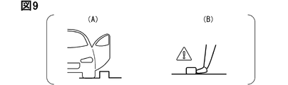
- the overview image indicating that there is a puddle near the door is an image that simply simulates a puddle near the door or the vehicle body as shown in FIG. 7, or an image that simulates a foot stepping on a puddle. .
- the information presentation processing unit F10 may display both the text indicating that there is a puddle and the icon image side by side in the display area corresponding to the line-of-sight direction of the driver.
- the information presentation processing unit F10 may display a text such as "Caution” and an icon image indicating that there is a puddle under your feet side by side.
- step S106 the alighting road surface monitoring unit F61 analyzes the image acquired in step S103 to determine whether or not the alighting spot has a recess such as a gutter. If there is a concave portion in the exit spot, an affirmative determination is made in step S106 and step S107 is carried out. On the other hand, if there is no recess in the exit spot, a negative determination is made in step S106 and step S108 is executed.
- step S107 the information presentation processing unit F10 displays text or a summary image indicating that there is a recess near the door in the display area corresponding to the driver's line of sight acquired in step S102.
- the text indicating that there is a recess near the door is, for example, "there is a recess under your feet" or "beware of the recess".
- the outline image indicating that there is a concave portion near the door is an image that simply simulates the concave portion near the door or the vehicle body as shown in FIG. .
- the information presentation processing unit F10 may display a text indicating that there is a concave portion and an icon image side by side in a display area corresponding to the line-of-sight direction of the driver.
- the information presentation processing unit F10 may display a text such as "Caution” and an icon image indicating that there is a recess at the foot side by side.
- step S108 the alighting road surface monitoring unit F61 analyzes the image acquired in step S103 to determine whether or not there are large stones, steps, blocks, bricks, or other low-profile solid objects in the alighting spot. If there is a three-dimensional object at the get-off spot, an affirmative decision is made in step S108 and step S109 is executed. On the other hand, if there is no three-dimensional object at the drop-off spot, a negative determination is made in step S106 and step S110 is executed.
- step S109 the information presentation processing unit F10 displays text or a summary image indicating that there is a three-dimensional object near the door in the display area corresponding to the line-of-sight direction of the driver acquired in step S102.
- the text indicating that there is a three-dimensional object near the door is, for example, "There is a three-dimensional object at your feet" or "Beware of three-dimensional object”.
- the overview image indicating that there is a three-dimensional object near the door is an image simulating a three-dimensional object near the door or the vehicle body as shown in FIG. be.
- the information presentation processing unit F10 may display a text indicating that there is a three-dimensional object and an icon image side by side in a display area corresponding to the line-of-sight direction of the driver.
- the information presentation processing unit F10 may display a text such as "Caution” and an icon image indicating that there is a three-dimensional object at the driver's feet side by side in a display area corresponding to the line-of-sight direction of the driver.
- step S110 the vehicle exterior condition acquisition unit F6 determines the safety when getting off the vehicle based on the output signal of the surroundings monitoring sensor 22. For example, it is determined whether or not there is another mobile object scheduled to pass within a predetermined distance from the driver's side door. If another moving body scheduled to pass within a predetermined distance from the driver's side door is detected, it is determined that the safety is low, and step S111 is executed. On the other hand, if no other moving body expected to pass within the predetermined distance from the driver's side door is detected, step S112 is executed.
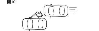
- step S111 the information presentation processing unit F10 performs approaching object alerting processing by displaying text or an outline indicating that another moving object is scheduled to pass near the door in the display area corresponding to the line-of-sight direction of the driver acquired in step S102.
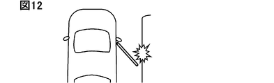
- Display an image The overview image indicating that another mobile object is scheduled to pass near the door is, for example, an overview image that indicates another vehicle that is scheduled to pass by the side of the own vehicle, as shown in FIG. 10 .
- the information presentation processing unit F10 may display text or a summary image prompting the driver to visually recognize the direction in which the approaching object exists.
- step S111 the information presentation processing unit F10 may turn on the in-vehicle lighting device 39 installed on the inner panel of the door for the driver's seat (so-called door trim) in red.
- the information presentation processing unit F10 may cause the in-vehicle speaker 35 to output a predetermined notification sound in accordance with the display of the text or summary image.
- step S112 the information presentation processing unit F10 displays, as safety notification processing, a text or a summary image indicating that there is no danger of collision detected in the display area corresponding to the line-of-sight direction of the driver acquired in step S102. You may Alternatively, text or an overview image may be displayed suggesting that the door be opened after checking the surroundings. In step S112, the information presentation processing unit F10 may suggest that the safety confirmation has been completed by turning on the interior lighting device 39 installed in the door trim in green. Note that step S112 is an optional element and may be omitted.
- the information presentation processing unit F10 moves to a place where there is no puddle. You may suggest that you park your car. Also, if the schedule information indicates that the driver is not in a rush at the moment, that is, that he has time to spare, the text advising him to move and park in a place free of puddles is also displayed at a given/ It may be displayed in a display area in the line-of-sight direction of the driver.
- the case where the schedule information indicates that the crew has time to spare is, for example, the case where there is no other schedule within 30 minutes from the current time.
- the HCU 1 may cooperate with the automatic parking ECU 27 and automatically move to a different location when a positive response is input from the driver to the proposal to change the parking position as described above. Further, the automatic parking ECU 27 may change the direction of parking, such as forward or backward, so as to avoid puddles.
- FIG. 11 ⁇ Example of application to getting off scene (Part 2)>
- Another operation example of the HCU 1 in a scene where the driver parks and gets off the vehicle will be described using the flowchart shown in FIG.
- a series of processes shown in FIG. 11 may alternatively be executed as a modified example of the display control process when getting out of the vehicle in FIG. 6, or may be executed in combination with/in parallel with the processes shown in FIG.
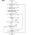
- the flowchart shown in FIG. 11 has steps S201 to S211 as an example.
- the process shown in FIG. 11 is performed sequentially at predetermined execution cycles while the vehicle's running speed is equal to or less than a predetermined threshold, for example. Note that this flow may be triggered by the detection of the driver's exiting motion by the exiting motion detection unit F2, and in this case, step S201 may be omitted.
- step S201 the exit motion detection unit F2 determines whether or not the driver has exited the vehicle. If the exit motion is not detected, a negative decision is made in step S201, and this flow ends. On the other hand, if the exiting motion is detected, an affirmative decision is made in step S201 and the process proceeds to step S202.
- step S202 the line-of-sight direction acquisition unit F1 acquires the line-of-sight direction of the driver, and the process proceeds to step S203.
- step S203 the vehicle exterior condition acquisition unit F6 acquires information on objects existing around the vehicle based on the output signal of the surroundings monitoring sensor 22, and the process proceeds to step S204.
- step S204 the opening obstacle detection unit F62 determines whether or not there is an opening obstacle based on the information acquired in step S203. If there is an obstacle for opening the door, the process proceeds to step S205. On the other hand, if there is no obstacle for opening the door, this flow ends.
- step S205 based on the relative position of the door-opening obstacle with respect to the driver's door, the allowable degree of opening, which is the degree to which the driver's door can be opened, is calculated, and the process proceeds to step S206.
- the allowable degree of opening indicates a range in which the driver's door can be opened without contacting an opening obstacle.
- the allowable opening can be calculated based on concepts such as angles, for example.
- the permissible degree of opening can be calculated, for example, as the degree of opening of the driver's door at which the distance between the obstacle to open the door and the driver's door is equal to or greater than a predetermined value (eg, 5 cm). ⁇ a in the figure indicates the allowable opening.
- step S206 the information presentation processing unit F10 reads the normal opening degree stored in the driver data storage unit M2, and proceeds to step S207. ⁇ d in the figure indicates the normal opening.
- step S207 the information presentation processing unit F10 compares the allowable opening calculated in step S205 with the normal opening read in step S206. Then, when the normal opening is larger than the allowable opening, step S208 is executed. On the other hand, when the normal opening is equal to or less than the allowable opening, step S209 is executed.
- step S208 the information presentation processing unit F10 displays a text or a summary image indicating that there is a possibility that the door will collide with another vehicle as a door collision warning in the display area corresponding to the line-of-sight direction of the driver acquired in step S202. to display. For example, when the driver's line of sight is directed to the vicinity of the shift lever, the above information is displayed on the display closest to the shift lever, such as the center display 32 .
- the outline image indicating that there is a possibility that the door will come into contact with another vehicle is, for example, an image showing a state in which the open door contacts another object, as shown in FIG.
- the information presentation processing unit F10 may display a text prompting the driver to slowly open the door as a door collision warning in a display area in the direction of the line of sight of the driver.
- the text prompting the user to open the door slowly may be "Please open slowly (carefully)".
- the driver does not need to think about a countermeasure compared to the case of presenting the possibility of a door collision itself, so convenience can be improved.
- the driver can recognize the reason in the process of opening the door according to the coping method notified by the system.
- steps S209 to S211 can be the same as that of steps S110 to S112, so the description is omitted.
- the lighting color of the interior lighting device 39 provided on the inner surface of the driver's door is used to indicate whether the door should be opened. A sense of distance between the door obstacle and the door may be notified.
- the information presentation processing unit F10 determines that the driver will get off at that time and that the automatic parking function will be used. You may suggest that you park at
- FIG. 13 ⁇ Example of application to getting off scene (Part 3)>
- the series of processes shown in FIG. 13 may be alternatively executed as a modification of the display control process at the time of getting off the vehicle described above, or may be executed in combination with/in parallel with the already described processes.
- the flowchart shown in FIG. 13 has steps S301 to S308 as an example.
- the processing shown in FIG. 13 is sequentially performed at predetermined execution cycles while the traveling speed of the own vehicle is equal to or less than a predetermined threshold, for example. Note that this flow may be triggered by the detection of the driver's exiting motion by the exiting motion detection unit F2, in which case step S301 may be omitted.
- step S301 the exit motion detection unit F2 determines whether or not the driver has exited the vehicle. If the exit motion is not detected, a negative decision is made in step S301, and this flow ends. On the other hand, if the exiting motion is detected, affirmative determination is made in step S301 and the process proceeds to step S302.
- step S302 the line-of-sight direction acquisition unit F1 acquires the line-of-sight direction of the driver, and the process proceeds to step S303.
- step S303 the vehicle exterior condition acquisition unit F6 acquires information on objects existing around the vehicle as an output signal from the surroundings monitoring sensor 22, and the process proceeds to step S304.
- step S304 the standby necessity determination unit F7 determines whether or not it is recommended to open the door and wait based on the information acquired in step S303. Specifically, it is determined whether or not there is an approaching object that is scheduled to pass within a predetermined distance from the driver's side door. If there is an approaching object that satisfies the condition, the process moves to step S305. On the other hand, if there is no approaching body that satisfies the condition, this flow ends.
- step S305 the information presentation processing unit F10 displays a text or a summary image suggesting waiting for the door to open in the display area corresponding to the line-of-sight direction of the driver acquired in step S302.
- the processing of step S305 can be the same as that of step S111. That is, the information presentation processing unit F10 may light the vehicle interior lighting device 39 installed on the door trim of the driver's seat in red, in addition to displaying an image suggesting waiting for the door to open. In addition, the information presentation processing unit F10 may output a predetermined notification sound from the in-vehicle speaker 35 in accordance with the display of the image.
- the content displayed in step S305 may be text or a summary image indicating the reason for recommending waiting for the door to open.
- step S306 the vehicle exterior condition acquisition unit F6 determines whether or not it is possible to exit the vehicle safely based on the output signal of the surroundings monitoring sensor 22. determine whether or not This determination corresponds to a process of determining whether or not it is no longer necessary to wait for the door to be opened. If there is no approaching object that is scheduled to pass near the door, an affirmative decision is made in step S306, and the process proceeds to step S307. On the other hand, if there is an approaching object scheduled to pass near the door, step S306 is performed periodically (for example, every second).
- step S307 the getting-off operation detection unit F2 determines whether or not the driver still intends to get off based on the images of the in-vehicle sensor 21 and the in-vehicle camera 23. For example, if it is possible to detect that the driver is holding the inner door handle or looking toward the outside of the door, it is determined that the driver still intends to get off the vehicle, and the process proceeds to step S308. On the other hand, if the driver has no intention of getting off the vehicle, various displays and lighting of the vehicle interior lighting device 39 are terminated, and then this flow is terminated. For example, when the driver performs an action other than preparing to get off, such as operating a smartphone, it is determined that the driver no longer intends to get off. In this case, this flow may be performed periodically in case the driver tries to get off the vehicle again.
- step S308 as in step S112, processing is performed to notify that it is possible to get off safely or that the reason for waiting has been resolved.
- step S308 is an optional element and may be omitted. That is, the information presentation processing unit F10 may express that the safety confirmation is completed by switching the lighting color of the in-vehicle lighting device 39 installed in the door trim of the driver's seat from red to green. Also, the content displayed in step S308 may be a text or a summary image indicating that the reason for waiting has disappeared or that the door may be opened.
- the HCU 1 similarly executes the processing from step S305 onward when a person is about to exit the parallel parked vehicle, more specifically, when it is detected that the front passenger door of the parallel parked vehicle is moving. sell.
- the waiting proposal may be performed in the same manner.
- FIG. 14 ⁇ Example of application to getting off scene (No. 4)>
- a series of processes shown in FIG. 14 may be alternatively executed as a modification of the display control process when getting off the vehicle described above, or may be executed in combination with/in parallel with the already described processes.
- the flowchart shown in FIG. 14 has steps S401 to S405 as an example.
- the processing shown in FIG. 14 is sequentially performed at predetermined execution cycles while the traveling speed of the own vehicle is equal to or less than a predetermined threshold, for example. Note that this flow may be triggered by the detection of the driver's exiting motion by the exiting motion detection unit F2, and in this case, step S401 may be omitted.
- step S401 the exit motion detection unit F2 determines whether or not the driver has exited the vehicle. If the exit motion is not detected, a negative decision is made in step S401, and this flow ends. On the other hand, if the exiting motion is detected, an affirmative decision is made in step S401 and the process proceeds to step S402.
- step S402 the line-of-sight direction acquisition unit F1 acquires the line-of-sight direction of the driver, and the process proceeds to step S403.
- step S403 the wind force acquisition unit F3 acquires wind speed information through communication with an external server, for example, and the process proceeds to step S404. Wv in the figure indicates the wind speed.
- the wind speed level may be specified by analyzing the electrical signal output from the external microphone 24 .
- step S404 the vehicle exterior condition acquisition unit F6 determines whether the wind speed acquired in step S403 exceeds a predetermined strong wind threshold. Thw in the figure indicates a strong wind threshold.
- the strong wind threshold can be, for example, 6.0 m/sec, 8.0 m/sec, 10.0 m/sec, or the like. This step corresponds to the process of determining whether or not the outside of the vehicle is in a strong wind state. If the acquired wind speed exceeds the strong wind threshold, the process moves to step S405. On the other hand, if the acquired wind speed does not exceed the strong wind threshold, this flow ends.
- step S405 the information presentation processing unit F10 displays text or a summary image indicating that there is a possibility that the door may open forcefully due to strong winds as a strong wind warning in the display area corresponding to the line-of-sight direction of the driver acquired in step S402. indicate.
- the overview image indicating that there is a possibility that the door may be opened vigorously by strong wind is, for example, an image schematically showing the wind and the opened door as shown in FIG. 15 .
- the information presentation processing unit F10 may display a text prompting the driver to open the door slowly or by gripping it firmly in a display area in the line of sight of the driver as a door collision warning.
- a text prompting the door to be opened carefully might be "Hold it tight to open it.”
- the HCU 1 may warn the driver to grip the door handle more strongly.
- the force with which the driver grips the inner door handle may be determined by analyzing an image captured by the in-vehicle camera 23, or a sensor may be provided on the inner door handle to detect the gripping force. If the driver is a person with weak muscles, such as an elderly person, the notification mode may be strengthened. Further, when the present disclosure is applied to a rear seat or the like, and if the occupant sitting in the target seat is a child or an elderly person, in step S405, the driver is instructed to open and close the door for the target seat. You can suggest to help.
- FIG. 16 ⁇ Example of application to a scene of parking in a parking lot of a facility>
- the series of processes shown in FIG. 16 can be executed in combination/in parallel with the display control process at the time of getting off described above.
- the flowchart shown in FIG. 16 has steps S501 to S509 as an example.
- the processing shown in FIG. 16 is sequentially executed in a predetermined execution cycle. Note that this flow may be triggered by the detection of entry into the facility-attached parking lot by the parking lot entry detection unit F8, in which case step S501 may be omitted.
- step S501 the parking lot entry detection unit F8 determines whether or not the vehicle has entered the facility-attached parking lot based on the signal from the navigation ECU 28. If the signal indicating that the vehicle has entered the parking lot associated with the facility has not been input, a negative determination is made in step S501, and this flow ends. On the other hand, when the signal indicating that the vehicle has entered the parking lot associated with the facility is input from the navigation ECU 28, an affirmative determination is made in step S501 and step S502 is executed. As described above, the determination of entry into the facility-attached parking lot may be performed by the parking lot entry detection unit F8 using various methods.
- step S502 the candidate section acquisition unit F41 acquires the position information of the parking section provided in the parking lot based on the detection result of the perimeter monitoring sensor 22 or the distribution data from the parking device, and proceeds to step S502.
- step S503 a candidate section is automatically selected from among the parking sections acquired in step S502 according to a preset rule (algorithm), and the process proceeds to step S504. It should be noted that the selection of the candidate section may be made based on the driver's operation, as described above.
- step S504 the parking position acquisition unit F4 refers to the driver data storage unit M2, acquires information such as the driver's driving skill level and preferences, and proceeds to step S505.
- step S505 based on the driver information acquired in step S504, it is determined whether or not a predetermined verification condition is satisfied.
- the verification condition here is a condition for verifying whether or not the candidate section is a section in which there is a high possibility that another vehicle will be parked in the adjacent section on the driver's seat side. When another vehicle is parked in the adjacent section on the driver's seat side, it becomes difficult to open and close the door depending on the size of the parking section.
- the verification condition can also be interpreted as a condition for verifying whether or not the selected candidate section is a section in which opening and closing of the door is easily performed.
- the parking position acquisition unit F4 determines that the verification conditions are satisfied when the driver's driving skill is at a low level. Further, when the door is likely to protrude from the parking frame when the door is opened by the normal opening degree of the driver, it may be determined that the verification condition is satisfied. In addition, if it is automatically/manually registered as driver data that other vehicles do not like parking in the adjacent section on the driver's seat side, it is determined that the verification conditions are satisfied. may
- step S506 is executed. On the other hand, if the verification conditions are not satisfied, this flow ends. Therefore, for example, when the driving skill of the driver is equal to or higher than a predetermined threshold value, the proposal to change the parking position, which will be described later, is not implemented.
- the adjacent parking probability acquisition unit F9 calculates the adjacent parking probability based on the usage probability data for each section acquired by wireless communication from the parking device or the parking history data of the own vehicle in the relevant section, The process moves to step S507.
- pn in the figure indicates the adjacent parking probability.
- the adjacent parking probability used in subsequent processing is preferably the probability that an adjacent vehicle exists on the driver's seat side at the time of leaving the garage.
- the adjacent parking probability acquisition unit F9 may estimate the time zone for exiting the parking lot based on the schedule information of the driver and the past visit history of the facility, and calculate the adjacent parking probability in the exit time zone.
- the future adjacent parking probability may be calculated from the usage probability data for each time period distributed from the parking lot device.
- step S507 it is determined whether or not the adjacent parking probability (pn) exceeds a predetermined probability threshold (Thp). If the adjacent parking probability exceeds the threshold for probability, step S508 is executed. On the other hand, if the adjacent parking probability is equal to or less than the probability threshold, step S509 is executed.
- the probability threshold can be, for example, 50%.
- step S508 the information presentation processing unit F10 displays text or a summary image suggesting parking in another section with a lower adjacent parking probability.
- a section with a smaller adjacent parking probability mainly corresponds to a section far from the entrance/exit of the facility.
- the display destination of the information is assumed to be a display area in the line-of-sight direction of the user. If an operation to change the section in which the vehicle is to be parked is received from the driver, processing for setting another section as the target parking position is started. By proposing a change of parking position when the adjacent parking probability value is high, it is expected to have the effect of eliminating in advance anxiety about the narrowness when exiting the parking lot.
- the HCU 1 cooperates with the automatic parking ECU 27 to execute parking assistance processing.
- the contents of the parking assistance process may be designed as appropriate.
- the automatic parking ECU 27 may automatically perform the steering, while the acceleration and deceleration may be left to the driver.
- the HCU 1 displays, on the center display 32 or the like, an image showing the positional relationship between the parking position and the own vehicle, or an overhead image obtained by synthesizing images of surrounding monitoring cameras.
- a bird's-eye view image is an image looking down on the own vehicle and its surrounding area from above.
- the composite image displayed as the parking assistance process may be a composite image showing the road surface in the traveling direction of the own vehicle with a part of the vehicle body transparent.
- FIG. 17 ⁇ Example of application to starting scene>
- the flowchart shown in FIG. 17 includes steps S601 to S606 as an example.
- the processing shown in FIG. 17 is performed when the power source for running is turned on. It should be noted that this flow may also be triggered by the fact that the seat belt is fastened, or that the driver's seat door is opened while the vehicle is parked.
- step S601 the vehicle exterior condition acquisition unit F6 acquires the current image data outside the vehicle room from the peripheral monitoring camera that is activated when the driving power source is turned on, and the process proceeds to step S602.
- the pre-start surroundings confirmation unit F63 detects animals present in the vicinity of the host vehicle by analyzing the image data acquired in step S602.
- the pre-start surroundings confirmation unit F63 detects an animal such as a cat existing in the vicinity area by comparing the outside image captured by the surroundings monitoring camera when the vehicle is parked with the outside image acquired in step S601.
- Animals to be detected may be cats, dogs, birds such as pigeons and chickens, rabbits, and raccoon dogs.
- the HCU 1 is configured to store the image data of the peripheral monitoring camera at that point in the storage 13 as data for comparison when the vehicle is parked.
- step S603 is executed.
- the information presentation processing unit F10 refers to the driver data stored in the driver data storage unit M2, and proceeds to step S604.
- step S604 the information presentation processing unit F10 determines whether the driver likes animals or the animal detected in step S602 based on the driver data read in step S603. If the driver likes animals or likes animals detected in step S602, step S605 is executed. On the other hand, if the driver does not like animals or does not like the animals detected in step S602, step S606 is executed.
- the information presentation processing unit F10 displays text or a summary image indicating the presence of animals.
- the display destination of the information is preferably a display area in the line-of-sight direction of the user, but may be a predetermined display.
- the information presentation processing unit F10 may project an image of a peripheral monitoring camera capturing an animal on the center display 32.
- FIG. the HCU 1 may drive the external speaker 36 so that the driver can speak to the animal.
- step S606 the information presentation processing unit F10 displays a text or a summary image suggesting outputting a predetermined sound effect for chasing away from the external speaker 36 in the display area in the direction of the user's line of sight.
- the chasing effect sound is a sound effect prepared in advance for chasing away animals present in the vicinity of the vehicle.
- the above configuration corresponds to a configuration that changes the content of the proposal depending on whether or not the detected animal corresponds to the driver's favorite animal.
- the detection target may be a pedestrian including a child. If a pedestrian is detected near the vehicle, the HCU 1 may suggest turning on the outside speaker 36 . According to this configuration, the driver himself/herself can use the outside speaker 36 to call attention to pedestrians.
- an image or text indicating an overview of the notification event or a recommended action is displayed in the display area corresponding to the direction of the driver's line of sight.
- the door display 34 displays a summary image or the like corresponding to the notification event.
- the HCU 1 of the present disclosure autonomously determines and displays information to be presented to the driver according to the detection target and the scene. Therefore, it is possible to present the information according to the situation to the driver in an easy-to-understand manner.
- the HCU 1 of the present disclosure proposes changes in the parking position, etc., after considering the driver's personality, schedule, driving skill, and the like. According to the configuration of the present disclosure, it is possible to further improve the convenience of the driver compared to a configuration in which a uniform proposal is made regardless of the driver.
- the display provided on the side mirror is assumed as the display provided on the door side as seen from the driver.
- the display provided in the side mirror has a small display screen, so it is difficult to display text and complicated overview images.
- the configuration provided with the door display 34 having a relatively large display area as in the present disclosure it is possible to present various information to the driver looking at the door.
- the HCU 1 may switch the doors from the locked state to the unlocked state based on the vehicle's entry into a specific unlocked area such as the entrance of a hotel, the entrance of a restaurant, a company, or an office building.
- the HCU 1 determines whether or not the vehicle has entered an unlocked area based on the output signal from the navigation ECU 28 (step S701 in FIG. 18).
- the unlocking area may be registered in the HCU 1 in advance as driver data by the driver's operation, or may be automatically registered based on the past visit history.
- the driver data management unit F5 may communicate with a predetermined server to acquire information on the hotel reserved by the driver, and register the entrance of the hotel in the unlocking area.
- the entrance of the office where the driver works may be registered in the unlocking area.
- the unlocked area can be an area where the driver has consented to switch the locked state of the door to the unlocked state. Similar to the determination of entry into a parking lot attached to a facility, various methods can be used to determine entry into an unlocked area, such as comparing location information with map data and detecting a specific signboard through image recognition.
- the HCU 1 switches the doors from locked to unlocked based on the fact that the vehicle has entered the unlocked area (step S702).
- a change in the locked state of the door may be performed in cooperation with the body ECU.
- the HCU 1 may output an unlock request signal to the body ECU to cause the body ECU to drive the door lock motor.
- the HCU 1 displays text or a summary image indicating that the doors have been switched to the unlocked state on the center display 32, HUD 33, etc. (step S703).
- the HCU 1 may only propose to switch the doors to the unlocked state based on the vehicle's entry into the unlocked area.
- a configuration has been described in which automatic unlocking or an unlocking proposal is performed based on the vehicle's entry into a predetermined unlocking area, but the present invention is not limited to this.
- the HCU 1 may automatically unlock or suggest unlocking based on detecting a person wearing a specific badge or uniform by analyzing the image of the surrounding surveillance camera. .
- a person wearing a specific badge or uniform may be a hotel doorman or an office security guard.
- the HCU 1 may be configured to execute control to refresh the body according to the time of arrival at the destination so that the driver can move smoothly after arriving at the destination.
- Refresh control is control for dealing with fatigue associated with driving. Refresh control is mainly performed in cooperation with the air conditioner 38 .
- the HCU 1 acquires the remaining arrival time, which is the remaining time until the destination is reached, from the navigation ECU 28 (step S801 in FIG. 19). Tr in the figure indicates the remaining arrival time. Then, the HCU 1 causes the air conditioner 38 to start refresh control (step S803) based on the fact that the remaining arrival time has become shorter than the predetermined refresh start threshold (step S802 YES). Tht in the figure is a refresh start threshold.
- the refresh start threshold can be set to, for example, 10 minutes or 15 minutes.
- Refresh control includes, for example, outputting scents such as mint and lemon, driving seat massage, and adjusting air conditioning temperature. The refresh control described above may be applied only when the total travel time by car is equal to or greater than a predetermined threshold (eg, 3 hours).
- the HCU 1 may gradually bring the target temperature of the air conditioner 38 closer to the outside temperature as refresh control.
- the display areas selectable by the HCU 1 are not limited to the above combinations.
- the rearview mirror (rearview mirror) is configured as an electronic mirror using a display
- the rearview mirror can also be included in the display area selectable by the HCU 1 as a display destination of information.
- the combination of display areas selectable by the HCU 1 and the individual specific positions can be changed as appropriate.
- the door display 34 may be a device that displays an image on the window glass Wg adjacent to the driver's seat by irradiating the window glass Wg adjacent to the driver's seat with image light.
- the door display 34 may be implemented using a projector 41 for emitting image light and a screen 42 as shown in FIG. 20, for example.
- the screen 42 is a transparent film for reflecting the image light toward the vehicle interior, and is attached to the vehicle interior side surface of the window glass Wg to which the image light is irradiated.
- the screen 42 and the window glass Wg may be integrated.
- a mirror 43 may be interposed between the projector 41 and the screen 42 to magnify and reflect the image light emitted from the projector 41 toward the screen 42 .
- Mirror 43 is preferably a concave mirror.
- Mirror 43 may be a plane mirror.
- the projector 41 and the mirror 43 are arranged on the surface of the roof portion Rf on the vehicle interior side, that is, on the vehicle interior ceiling.
- FIG. 21 indicates the display area by the projector 41.
- FIG. The display area 34a formed on the side window of the door also corresponds to the door display area.
- the projector 41 may be configured to project the image light onto a region within a predetermined distance from the lower end of the window frame in the door trim for the driver's seat. With such a configuration, the image can be displayed at a position corresponding to the direction of the line of sight of the driver, such as the upper panel of the door trim or the armrest.
- the projector 41 and the mirror 43 may be configured to dynamically change their orientation with respect to the vehicle using an actuator such as a motor so that an image can be projected at any position inside the vehicle. In that case, the display area (projection area) of the projector 41 may be controlled by the HCU1.
- the HCU 1 uses the projector 41 to display the outline image on the A pillar on the driver's seat side, the A pillar on the passenger's seat side, the front passenger's seat area of the instrument panel, the door on the passenger's seat side, etc., as shown in FIG. etc., can be displayed.
- 34c shown in FIG. 21 indicates the display area of the A pillar on the driver's seat side by the projector 41.
- 34d indicates the display area of the A pillar on the passenger seat side by the projector 41;
- 34e indicates a display area arranged on the front passenger door.
- 34f indicates a display area formed in the front passenger seat area of the instrument panel.
- a plurality of display areas may be realized by dynamically adjusting the posture of the projector 41 using a motor or the like.
- a plurality of projectors 41 may be arranged on the ceiling of the passenger compartment so as to form a plurality of display areas.
- Some or all of the display areas indicated by 34c to 34e may be realized using a transmissive skin display or the like instead of the projector 41.
- the present disclosure is applicable to a wide variety of vehicles traveling on roads.
- the present disclosure can be mounted on various vehicles capable of traveling on roads, such as trucks and trailers, in addition to four-wheeled vehicles.
- a vehicle to which the system/device/method, etc. of the present disclosure is applied may be an owner car owned by an individual, or may be a service car.
- a service car refers to, for example, a vehicle that is provided for a car sharing service or a vehicle rental service.
- the present disclosure may be applied to robotic taxis, unmanned buses, etc., where no driver is on board.
- part or all of the present disclosure can be implemented as an information presentation device for a passenger sitting in a seat other than the driver's seat, such as a passenger seat.
- the predetermined seat is not limited to the driver's seat, but may be the passenger's seat or the rear seat.
- the rear seats can be divided into right rear seats and left rear seats.
- the door adjacent to the passenger seat refers to the door for the passenger seat.
- the door adjacent to the right rear seat refers to the door for the right rear seat provided in the vehicle.
- a door adjacent to a certain seat is a door for the relevant seat, and can be understood as a seat closest to the relevant seat.
- the apparatus, systems, and techniques described in the present disclosure may be implemented by a special purpose computer comprising a processor programmed to perform one or more functions embodied by the computer program. .
- the apparatus and techniques described in this disclosure may also be implemented using dedicated hardware logic.
- the apparatus and techniques described in this disclosure may be implemented by one or more special purpose computers configured in combination with a processor executing a computer program and one or more hardware logic circuits.
- some or all of the functions provided by the HCU 1 may be implemented as hardware.
- Implementation of a function as hardware includes implementation using one or more ICs.
- a CPU, an MPU, a GPU, a DFP (Data Flow Processor), or the like can be used as a processor (arithmetic core).
- HCU 1 may be implemented by combining multiple types of arithmetic processing units. Some or all of the functions provided by the HCU 1 may be implemented using a system-on-chip (SoC), FPGA, ASIC, or the like.
- SoC system-on-chip
- FPGA Field-Programmable Gate Array
- ASIC is an abbreviation for Application Specific Integrated Circuit.
- the computer program may be stored in a computer-readable non-transitory tangible storage medium as instructions executed by a computer.
- a HDD Hard-disk Drive
- an SSD Solid State Drive
- a flash memory an SD (Secure Digital) card, or the like can be used as a program storage medium.
- the scope of the present disclosure also includes, for example, a program for causing a computer to function as HCU1, a non-transitional substantive recording medium such as a semiconductor memory recording this program, a system having HCU1 as a component, and the like.
Landscapes
- Engineering & Computer Science (AREA)
- Mechanical Engineering (AREA)
- Transportation (AREA)
- Automation & Control Theory (AREA)
- General Physics & Mathematics (AREA)
- Physics & Mathematics (AREA)
- Human Computer Interaction (AREA)
- Chemical & Material Sciences (AREA)
- Combustion & Propulsion (AREA)
- Life Sciences & Earth Sciences (AREA)
- Atmospheric Sciences (AREA)
- Traffic Control Systems (AREA)
- Control Of Driving Devices And Active Controlling Of Vehicle (AREA)
Abstract
HCUは、複数の表示領域の中から情報の表示先を選択的に採用可能に構成されている。HCUは、車内カメラの画像に基づいてドライバの視線方向を取得する。HCUは、車載センサの出力信号に基づいてドライバの降車動作を検出した場合、運転席用ドア付近の路面に、例えば水溜まりや段差、他車両等といった、注意が必要な事象が存在する場合には、その内容又は対処法を具体的に示す画像を、ドライバの視線方向に対応する表示領域に表示する。
Description
この出願は、2021年5月12日に日本に出願された特許出願第2021-081241号を基礎としており、基礎の出願の内容を、全体的に、参照により援用している。
本開示は、車両の乗員に対して車外の懸念事項に関する情報を提供する情報提示装置に関する。
特許文献1には、自車両の後方から自転車や自動車などが接近している状況において乗員がドアを開けようとする挙動を検出した場合に、車内のドアノブ付近に設けられた警告灯を点灯させるとともに、スピーカから警告音を出力する構成が開示されている。
乗員に警告が発せられるシーンとしては、特許文献1に開示される後方からの車両の接近の他に、車両鍵の置き忘れ、走行用電源の切り忘れなど、多様なものがある。また、走行用電源がオン、かつ、シフトポジションが前進ポジションである状態で、運転席用ドアが開いたり、シートベルトの装着を解除したりした場合にも、警報音や警告灯の提示による警告が行われうる。
このように乗員への警告は、多様な事象に対して行われるため、警告音が出力されたり、警告灯が点灯されたりしても、乗員は直感的にその警告の理由を特定することが難しい。その結果、乗員を困惑させてしまう恐れがある。また、警告内容が不明であるとその対処法も不明である。故に、警告音が出力された場合、乗員は、その理由と対処法を自分で考える必要があった。
そのような課題に対し、警告対象の内容(理由)を音声メッセージで出力する構成も考えられるが、音声メッセージの場合、メッセージの出力開始から理由を示すキーワードが出力されるまで乗員はその原因を特定することができない。換言すれば音声メッセージでは、即座に/相対的に短い時間で、警告されている内容や対処法を理解できない。
想定構成として、メータディスプレイ又はセンターディスプレイに、警告内容を示す画像を表示する構成も考えられるが、例えば降車シーンにおいては、乗員は必ずしも車両前方に目を向けているとは限らない。警告内容の詳細情報をメータディスプレイ等、常に一定のディスプレイに表示する構成では、当該情報表示に乗員が気づきにくいといった課題があった。
本開示は、上記の検討又は着眼点に基づいて成されたものであり、その目的の1つは、通知内容を乗員が認識しやすい情報提示装置を提供することにある。
ここに開示される情報提示装置は、車両に設けられた所定の座席の乗員に対する情報の表示先を、複数の表示領域の中から選択可能に構成された情報提示装置であって、複数の表示領域の中には、少なくとも座席に隣接するドアに形成されているドア表示領域が含まれており、車外状況に関連する情報を、複数の表示領域の何れかに表示する表示処理部と、乗員の視線方向を示す情報を取得する視線方向取得部と、を備え、表示処理部は、乗員の視線方向に応じて車外状況に関連する情報の表示場所を変更するように構成されている。
以上の構成によれば、乗員の視線方向に対応する表示領域に、例えば警告対象の概要を示すテキスト又は画像を表示可能となる。その結果、乗員による通知内容の認識性を高めることが可能となる。
なお、請求の範囲に記載した括弧内の符号は、一つの態様として後述する実施形態に記載の具体的手段との対応関係を示すものであって、本開示の技術的範囲を限定するものではない。
以下、本開示の実施形態について図を用いて説明する。図1は、本開示に係る情報提示装置としてのHCU1の概略的な構成の一例を示す図である。HCU1は、HMI(Human Machine Interface)の作動を制御する装置であって、HMI Control Unitの略である。
以下では、一例として運転席の乗員(つまりドライバ)に対する情報提示を制御する場合について説明する。ドライバは車両の使用者であるため、ユーザと呼ぶ事もできる。なお、本開示は助手席の乗員や、後部座席の乗員への情報提示制御にも適用可能である。本開示にかかる情報提示対象を助手席乗員等に適用する場合、以下の説明は情報提示対象の座席に対応するように適宜変更して実施することができる。以下では車両の右側に運転席が設けられている場合について例示する。故に車両右側が座席側方向に対応する。本開示は運転席が左側に設けられた車両に適用されても良い。その場合は車両左側が座席側方向に対応する。
便宜上、HCU1が搭載されている車両のことを自車両/搭載車両とも記載する。以下の説明における前後、左右、上下の各方向は、自車両を基準として規定される。具体的に、前後方向は、自車両の長手方向に相当する。左右方向は、自車両の幅方向に相当する。上下方向は、自車両の高さ方向に相当する。別の観点によれば、上下方向は、前後方向及び左右方向に平行な平面に対して垂直な方向に相当する。
図1に示すようにHCU1は、多様な車載装置と接続されて使用される。例えばHCU1は、種々の車載センサ21、周辺監視センサ22、車内カメラ23、車外マイク24、入力装置25、V2X車載器26、自動駐車ECU27、及びナビゲーションECU28と接続されている。また、HCU1は、メータディスプレイ31、センターディスプレイ32、HUD33、ドアディスプレイ34、車内スピーカ35、車外スピーカ36、路面ライト37、空調装置38、及び車内照明装置39と接続されている。なお、部材名称としてのHUDは、ヘッドアップディスプレイ(Head-Up Display)を意味する。また、部材名称中のECUは、Electronic Control Unitの略であって、電子制御装置を指す。V2XはVehicle to X(everything/something)の略で、車を様々なものをつなぐ通信技術を指す。V2Xの「V」は自車両としての自動車を指し、「X」は、歩行者や、他車両、道路設備、ネットワーク、サーバなど、自車両以外の多様な存在を指しうる。
HCU1と種々の車載装置とは専用線で接続されていても良いし、車両内ネットワークを介して接続されていてもよい。また、HCU1と車載装置との間にはECUが介在していてもよい。便宜上、HCU1に連なる車載装置とHCU1とを含む構成を車載システムSysと記載する。
車載センサ21は、車両の状態やドライバの運転操作の内容を示す物理状態量を検出するセンサである。車載センサ21としては、例えば、車速センサ、加速度センサ、操舵角センサ、シフトポジションセンサ、アクセルペダルセンサ、ブレーキペダルセンサ等が挙げられる。なお、アクセルペダルセンサはアクセルペダルの踏み込み量/踏み込み力を検出するセンサである。ブレーキペダルセンサはブレーキペダルの踏み込み量/踏み込み力を検出するセンサである。また、車載センサにはパーキングブレーキの作動状態や、自車両の電源状態を検出するセンサ/スイッチなども含まれる。運転席のシートベルトセンサや、着座センサも車載センサ21に含まれる。シートベルトセンサはシートベルトの装着状態を検出するセンサである。着座センサは、人間が着座していることを検知するセンサであって、例えばシート毎に設けられている。着座センサは、例えば、各座席の着座面に埋設された圧力センサとすることができる。
その他、インナードアハンドルセンサや、車内マイクなども車載センサ21の概念に含まれる。インナードアハンドルとは、運転席用のドアの内側に設けられたドアハンドルである。インナードアハンドルセンサは、ドライバがインナードアハンドルを握っていること、より好ましくはその把持力(把持圧)を検出するセンサである。インナードアハンドルセンサは、インナードアハンドルに設けられた静電容量式あるいは感圧式のタッチセンサとすることができる。インナードアハンドルセンサは、インナードアハンドルの極近傍(例えば5cm以内)を検知範囲とする赤外線センサであってもよい。車内マイクはドライバの発話音声を取得するマイクであって、運転席付近に設けられている。
周辺監視センサ22は、自車両周辺の外部環境についての情報を収集する装置である。周辺監視センサ22としては、例えば、カメラ、ミリ波レーダ、LiDAR(Light Detection and Ranging/Laser Imaging Detection and Ranging)、ソナー等を採用することができる。なお、ミリ波レーダは、所定方向に向けてミリ波又は準ミリ波を送信するとともに、当該送信波が物体で反射されて返ってきた反射波の受信データを解析することにより、自車両に対する物体の相対位置や相対速度を検出するデバイスである。LiDARは、レーザ光を照射することによって、検出方向ごとの反射点の位置を示す3次元点群データを生成するデバイスである。ソナーは探査波としての超音波を発信することにより、障害物を検出するセンサである。
ここでは一例として車載システムSysは図2に示すように、前方カメラ22a、後方カメラ22b、右側方カメラ22c、左側方カメラ22dを周辺監視センサ22として備える。前方カメラ22a、後方カメラ22b、右側方カメラ22c、及び左側方カメラ22dは周辺監視カメラと呼ぶことができる。また、車載システムSysは周辺監視センサ22として複数のソナー22hを備える。
前方カメラ22aは、車両前方を所定の画角で撮像するカメラである。前方カメラ22aは、例えばフロントガラスの車室内側の上端部や、フロントグリル等に配置されている。後方カメラ22bは、車両後方を所定の画角で撮像するカメラである。後方カメラ22bは、例えばリアナンバープレート付近やリアウインドウ付近など、ボディ背面部の所定位置に配置されている。なお、周辺監視センサ22の搭載位置の説明において、或る部材の「付近」とは、当該部材から例えば30cm以内となる範囲を指す。例えばナンバープレート付近とはナンバープレートから30cm以内となる範囲を指す。
右側方カメラ22c及び左側方カメラ22dは、車両側方を所定の画角で撮像するカメラであって、例えばサイドミラーや、ボディの左右側面の所定位置、Aピラーの付け根付近に配置されている。ここでは運転席が車室内の右側に設けられているため、右側方カメラ22cが運転席用のドア付近を撮像範囲に含む車室外カメラに相当する。右側方カメラ22cと左側方カメラ22dを区別しない場合には単に側方カメラとも記載する。
複数のソナー22hは、フロント/リアバンパや、フェンダー、ドアパネルなど複数箇所に分散配置されている。例えば、フロントバンパの右側コーナー部から左側コーナー部にかけて4つのソナー22hが分散配置されている。また、自車両のリアバンパの右側コーナー部から左側コーナー部にかけて、4つのソナー22hが分散配置されている。このようなソナー22hの配置態様により、車載システムSysは自車両の前方又は後方に存在する物体を検出可能となる。一部のソナー22hは、車両側方に向けて超音波を発するように、サイドシルやフェンダー、ドアパネルに取り付けられていてもよい。
もちろん、車載システムSysはミリ波レーダやLiDARを備えていても良い。ソナー22hや、ミリ波レーダ、LiDARは物体との距離情報を取得可能なセンサであるため、測距センサと呼ぶことができる。また、車載システムSysは車体の底部の下方、つまり床下を検知範囲とするソナーである床下ソナーや、床下を撮像する床下カメラを備えていてもよい。床下カメラも周辺監視カメラに含めることができる。
上記の種々の周辺監視センサ22は、例えば、所定の検出対象物を検出するとともに、当該検出物の自車両に対する相対位置等を特定する。そして、検出物の位置や種別等を示す検出結果データを、HCU1や自動駐車ECU27(以降、HCU1等)に逐次提供する。なお、画像データに基づき物体を認識する機能はHCU1又は自動駐車ECU27が備えていても良い。画像データには映像信号も含まれる。
ここでの検出対象物とは、例えば、歩行者、人間以外の動物、他車両、道路沿いに設置される構造物などである。他車両には自転車や原動機付き自転車、オートバイも含まれる。道路沿いに設置される構造物とは、例えば、ガードレール、縁石、樹木、電柱、道路標識、信号機などである。また、本実施形態ではより好ましい態様として、レーン区画線等の路面標示や、路上の落下物なども周辺監視カメラの検出対象物として登録されているものとする。路面標示には、駐車場の駐車区画に記載されている駐車区画番号なども含まれうる。なお、前方カメラ22aなどの周辺監視カメラは、映像信号をHCU1等に出力しても良い。
検出物の位置は、例えば自車の所定の基準点を原点とする3次元座標系である車両座標系で表現される。この車両座標系を構成するX軸は車両の左右方向に平行であって、例えば右方向を正方向とするように設定されている。Y軸は車両の前後方向に平行であって、車両の前方に向かう方向を正方向とするように設定されている。Z軸は車両高さ方向に対応するように設定される。なお、車両座標系はZ軸を省略した2次元座標系であってもよい。
車内カメラ23は、運転席の乗員を撮像するように配されているカメラ(以降、車室内カメラ)である。車内カメラ23は、車室内全体を撮像可能なように、例えばオーバーヘッドコンソールなど、車室内天井部に配されていてもよい。車内カメラ23としては例えばドライバステータスモニタ(DSM:Driver Status Monitor)を採用することができる。DSMは、ドライバの顔画像に基づいてドライバの視線方向や挙動を検出する装置である。DSMは、例えば近赤外光源と、近赤外カメラと、これらを制御する制御モジュールと、を含む。DSMは、近赤外カメラが運転席のヘッドレストが存在する方向に向いた姿勢にて、例えばステアリングコラム部の上面、又はインストゥルメントパネルの上面等に設置されている。なお、DSMを構成するカメラは可視光カメラであってもよい。車内カメラ23は、ドライバの画像から抽出したドライバ状態情報をHCU1に出力する。
ドライバ状態情報には、例えばドライバの顔の向きや、視線方向などを含む。なお、ドライバの画像解析に基づいてドライバの視線方向を検出する機能は、HCU1が備えていても良い。その場合、車内カメラ23はドライバの顔部画像をHCU1に出力可能に構成されていればよい。
車外マイク24は、車両の外面部に配置されているマイクである。車外マイク24は、例えば車両に乗車しようとするドライバの音声を取得しやすいように、運転席用のドアやドア周り、例えばAピラーなどに設置されている。車外マイク24は外部の音を電気信号に変換してHCU1に出力する。
入力装置25は、車載システムSysに対するドライバの指示を受け付けるための操作部材である。入力装置25は、ステアリングホイールのスポーク部に設けられたメカニカルスイッチ(いわゆるステアスイッチ)であってもよいし、ドライバの発話内容を認識する音声入力装置であってもよい。また、入力装置25は、例えばセンターディスプレイ32など、インストゥルメントパネルに設けられたディスプレイの表示パネル上に積層されたタッチパネルであってもよい。入力装置25は、当該装置に対してユーザが行った操作に対応する電気信号をユーザ操作信号としてHCU1に出力する。ユーザ操作信号は、ユーザの操作内容を示す情報を含む。
V2X車載器26は、自車両が他の装置と無線通信を実施するための通信モジュールである。V2X車載器26は、例えばLTE(Long Term Evolution)や4G、5Gなどに準拠した無線通信であるセルラー通信を実施可能に構成されている。V2X車載器26は、外部サーバや路側機などから、時刻ごとの降水確率等の天気情報を取得する。また、V2X車載器26は、Wi-Fi(登録商標)や、Bluetooth(登録商標)に準拠した通信である狭域通信を実施可能に構成されていてもよい。その他、V2X車載器26は、例えばDSRC(Dedicated Short Range Communications)など、車両用の狭域通信規格に準拠した通信を実施可能に構成されていても良い。V2X車載器26は、各種通信規格で使用される周波数の電波を送受信可能なアンテナや、変復調を行うICなどを含む。
自動駐車ECU27は、周辺監視センサ22から入力された車両周辺の画像及び検出物体の位置等の情報に基づいて、目標駐車位置に自車両を自動的に駐車させるECUである。自動駐車ECU27は、自動駐車の実行がドライバによって指示された地点から目標駐車位置まで、車輪の角度や走行速度を自動制御し、目標駐車位置まで自律的に自車両を移動させる。ここでの自動駐車は、いわゆるドライバがスマートフォン等といった車両と紐付けられたデバイスを用いた遠隔操作によって、車両を自律的に駐車させる態様も含まれる。例えば自動駐車ECU27は、ドライバとしてのユーザがスマートフォンに表示される所定の自動駐車ボタンを押下していることを条件に、目標駐車位置に向かって自車両を自律的に走行させる制御を実施するように構成されていても良い。
なお、自動駐車ECU27は、自車両と紐付けられた携帯端末からの指示信号をトリガに、駐車状態にある自車両をパワーオンして、ドライバが指定した位置、又はドライバの近くまで自律的に走行させる、自動出庫制御を実行可能に構成されていても良い。自動駐車ECU27は例えばドライバが自車両から所定距離以内に存在することを条件として自動駐車制御や自動出庫制御を実行可能に構成されていてもよい。自動駐車ECU27は、駐車場に設けられたインフラ設備と協調して自動駐車や自動出庫を行うものであっても良い。
ナビゲーションECU28は、車両の現在位置に応じた地図画像の表示及び経路案内を行う装置である。ナビゲーションECU28は、例えば地図データベースとGNSS(Global Navigation Satellite System)受信機を有している。GNSS受信機は、複数の測位衛星からの測位信号を受信することで、当該GNSS受信機の現在位置を逐次(例えば100ミリ秒毎に)検出するデバイスである。ナビゲーションECU28が使用する地図データは、施設に付随する駐車場の位置情報などを含む。ナビゲーションECU28は自車両の位置情報や、周辺地図情報をHCU1に出力する。また、ナビゲーションECU28はより好ましい態様として、自車両の位置情報と地図データに基づき、施設に付随する駐車場である施設付随駐車場に自車両が入ったことを示す信号をHCU1に出力する。
メータディスプレイ31は、インストゥルメントパネルにおいて運転席の正面に位置する領域に配置されているディスプレイである。ディスプレイとしては液晶ディスプレイや有機EL(Electro-Luminescence)ディスプレイなどを採用可能である。
センターディスプレイ32は、インストゥルメントパネルにおいて車幅方向中央付近に配置されているディスプレイである。例えば、センターディスプレイ32は、シフトレバー/シフトボタン付近に配置されている。センターディスプレイ32は、センターコンソールに配置されたディスプレイであってもよい。
HUD33は、HCU1やナビゲーションECUなどから入力される制御信号及び映像データに基づき、フロントガラスの所定領域に画像光を投影することにより、ドライバによって知覚されうる虚像を映し出すデバイスである。HUD33は、車両の前方の風景と重畳した画像を表示する。図3における33aはHUD33による画像の表示領域(投影領域)を示している。
ドアディスプレイ34は、運転席用のドアに設けられたディスプレイである。例えばドアディスプレイ34は、図3に示すように運転席用のドアトリムのうち、窓枠の下端部に沿って配置されている。ドアディスプレイ34は、ドアトリムの形状に沿うように湾曲状の表示面を備えていてもよい。ドアディスプレイ34としては、例えば光透過表皮ディスプレイを採用することができる。光透過表皮ディスプレイは、光を透過させる人工表皮を有するディスプレイである。ドアディスプレイ34は有機ELディスプレイや液晶パネル等を用いて実現されうる。ドアディスプレイ34の表示領域の大きさは、多様なテキスト又は概要画像が表示可能なように、縦3cm、横5cm以上に設定されていることが好ましい。例えばドアディスプレイ34は、縦5cm、横20cm程度に設定されている。ここでの縦横はドアディスプレイ34の表示領域のサイズを説明するための概念であって、縦方向は車両の高さ方向又は車幅方向に、横方向は車両の前後方向に対応する。ドアディスプレイ34の表示画面がドア表示領域に相当する。
メータディスプレイ31、センターディスプレイ32、HUD33、ドアディスプレイ34のそれぞれは、HCU1から入力された信号に応じた画像を表示する。メータディスプレイ31やHUD33は、運転席の正面方向に位置する表示領域である前方表示領域を形成するデバイスに相当する。センターディスプレイ32は、前方表示領域よりも助手席側に位置する表示領域である助手席側表示領域を提供するデバイスに相当する。本開示のHCU1は、情報画像の表示先として、前方表示領域、助手席側表示領域、及びドア表示領域を選択的に採用可能に構成されている。各表示領域は、それぞれ異なるデバイスが形成する表示領域であって、車内の実空間において5cm以上離れるように分散配置されている。
車内スピーカ35は、車室内に設けられたスピーカである。車内スピーカ35は例えばインストゥルメントパネルなどに設けられている。車外スピーカ36は、車両の外面部に設けられたスピーカである。車外スピーカ36は車体底部や、運転席用のドア付近に配置されている。車外スピーカ36は主として車両近傍にいる人物とのコミュニケーションをとるためのスピーカである。車外スピーカ36は、車体下に入り込んでいる猫などの動物に向けて車内にいるドライバが声をかけたり、当該動物を移動させるための音を出したりするためにも供される。車内スピーカ35及び車外スピーカ36はそれぞれ、HCU1から入力された電気信号を音に変換して出力する。音との表現には、音声、音楽も含まれる。
路面ライト37は、運転席用のドア付近の路面を照らす照明装置である。路面ライト37は、例えば運転席側のサイドミラーや、運転席用のドアの下端部、運転席側のサイドシル付近に設けられている。路面ライト37はLED等の光源素子を含む。路面ライト37は、HCU1からの指示信号に基づき、当該信号に応じた色、明るさで路面の所定領域を照らす。
空調装置38は、設定温度に応じて温度が調整された空気である空調空気を車両に設けられた吹出口から出力する装置である。空調装置38は、例えば一つの冷媒回路で暖房と冷房とを行うことが可能なヒートポンプサイクルによって冷暖房を実施可能に構成されている。また、空調装置38は、予めセットされた香料を車室内に噴射するアロマシューターとしての機能を備える。例えば空調装置38は、レモンやミントといったリフレッシュ効果が期待できる香りを車室内に出力可能に構成されている。
車内照明装置39は、車室内に配置された照明装置である。車内照明装置39は、例えばドアトリム及びインストゥルメントパネルにおいて、部品のつなぎ目や縁部に沿うように複数の光源がライン状に配置された照明装置とすることができる。車内照明装置39は、例えば光が内装部品のつなぎ目から漏れ出るように構成されている。また、車内照明装置39は、足元などを間接的に照らす間接照明として構成されていても良い。車内照明装置39は、いわゆるアンビエントライトとして構成されていても良い。
<HCU1の構成について>
HCU1は、種々のディスプレイ/プロジェクタ等を用いたドライバへの情報提示を統合的に制御するコンピュータである。HCU1は、プロセッサ11、RAM(Random Access Memory)12、ストレージ13、通信インターフェース14(図中のI/O)、及びこれらの構成を接続するバスラインなどを備えた、コンピュータとして構成されている。
HCU1は、種々のディスプレイ/プロジェクタ等を用いたドライバへの情報提示を統合的に制御するコンピュータである。HCU1は、プロセッサ11、RAM(Random Access Memory)12、ストレージ13、通信インターフェース14(図中のI/O)、及びこれらの構成を接続するバスラインなどを備えた、コンピュータとして構成されている。
プロセッサ11は、例えばCPU(Central Processing Unit)等の演算コアである。プロセッサ11は、RAM12へのアクセスにより、種々の処理を実行する。RAM12は揮発性のメモリである。通信インターフェース14は、HCU1が他の装置と通信するための回路である。通信インターフェース14は、アナログ回路素子やICなどを用いて実現されればよい。
ストレージ13は、フラッシュメモリ等の不揮発性の記憶媒体を含む構成である。ストレージ13には、コンピュータをHCU1として機能させるためのプログラムである表示制御プログラムが格納されている。プロセッサ11が表示制御プログラムを実行することは、表示制御プログラムに対応する方法である表示制御方法が実行されることに相当する。また、ストレージ13には、ドライバのスケジュールや性格などを示すデータが登録されている。
HCU1は、プロセッサ11がストレージ13に保存されている表示制御プログラムを実行することにより図4に示す各機能部を提供する。つまり、HCU1は、視線方向取得部F1、降車動作検出部F2、風力取得部F3、駐車位置取得部F4、ドライバデータ管理部F5、及び車外状況取得部F6を備える。また、HCU1は、待機要否判定部F7、駐車場進入検出部F8、隣接駐車確率取得部F9、及び情報提示処理部F10を備える。駐車位置取得部F4は、サブ機能部として候補区画取得部F41を備える。車外状況取得部F6はサブ機能部として、降車路面監視部F61及び開扉障害物検出部F62を備える。各機能部が取得又は生成したデータは、RAM12などのメモリに一時保存され、他の機能部による参照により使用される。
また、HCU1は、表示情報記憶部M1及びドライバデータ記憶部M2を備える。表示情報記憶部M1は、所定の通知対象事象ごとの表示用データを記憶している。通知対象事象とは、車外に生じているドライバに通知すべき事象であって、例えばドライバの安全性や利便性を損ないかねない事象を含む。なお、安全性にかかる通知対象事象は、注意喚起/警告の対象とする事象に相当する。
表示用データの内容は、例えば通知対象とする事象の概要、又は、当該事象に対してドライバが取るべき行動パターンを示す推奨行動である。表示用データは、概要又は推奨行動を示すテキストであっても良いし、概要又は推奨行動を示す模式的に示す概要画像であってもよい。
概要画像とは、注意対象の内容や、提案内容を示す画像要素を含む画像である。概要画像は、注意対象の具体的な内容を含まない単なる注意喚起画像とは相違する。注意喚起画像とは、図5の(A)や(B)のように感嘆符記号/エクスクラメーションマークと、丸又は三角などの図形を組み合わせたアイコン画像を指す。注意喚起画像は、それだけ見ても、ドライバは何に注意すればよいのか、又は、何をすればよいのかが不明な画像に相当する。対して概要画像は、注意対象あるいは対処法(推奨行動)を示す画像要素を含む画像である。注意喚起の対象とする事象ごとの推奨行動や概要画像の詳細は別途後述する。
ドライバデータ記憶部M2はドライバのスケジュール等、パーソナルなデータを記憶している。ドライバデータ記憶部M2はより細かい要素として、スケジュール記憶部M2a、性格記憶部M2b、愛好動物記憶部M2c、通常開度記憶部M2d、及び習熟度記憶部M2eを備える。スケジュール記憶部M2aは、ドライバのスケジュールデータの保存領域である。性格記憶部M2bは、ドライバがきれい好きか、せっかちか、几帳面か、大雑把か、などといったドライバの性格を示すデータの保存領域である。愛好動物記憶部M2cは、ドライバが好きな動物を示すデータの保存領域である。愛好動物記憶部M2cは性格記憶部M2bと統合されていても良い。
通常開度記憶部M2dは、日常的なドアの開き度合いである通常開度を示すデータの保存領域である。通常開度は、ドライバの車両の使用履歴に基づいて学習されても良いし、ドライバによって登録されてもよい。例えば登録モード時にドライバが実施したドアの開閉操作に基づいて、通常開度が決定されても良い。通常開度は、角度などによって表現されうる。なお、通常開度記憶部M2dは、通常開度に加えて、ドアを開ける速度などを通常開度に対応付けて記憶していても良い。習熟度記憶部M2eは、運転スキルの高さ、換言すれば運転の習熟度を示すデータの保存領域である。運転スキルの高低は、急ブレーキや急ハンドルの実施頻度、駐車時における切り返し回数などをもとに自動的に決定されても良いし、ドライバによって手入力されてもよい。
表示情報記憶部M1及びドライバデータ記憶部M2はストレージ13が備える記憶領域を用いて実現されうる。なお、ドライバデータ記憶部M2は、RAM12が備える記憶領域の一部を用いて実現されていても良い。
視線方向取得部F1は、車内カメラ23の出力信号に基づき、ドライバの視線方向、顔の向き及び頭部位置を取得する。なお、ここでは一例として車内カメラ23がドライバの視線方向等を認識し、その認識結果を出力するものとするがこれに限らない。視線方向取得部F1が、車内カメラ23の撮影画像を解析して視線方向等を特定しても良い。
降車動作検出部F2は、ドライバの降車動作を検出する構成である。降車動作とはドアを開けて降車するための予備動作に相当する。降車動作は、降車予備動作と読み替えることができる。降車動作を検出することはドライバがドアをあけようとしていると判定することに対応する。降車動作とは、例えば、シフトレバーをパーキングポジションに設定する行為や、走行用電源をオフにすること、パーキングブレーキンをオンに設定すること、シートベルトを外すこと、インナードアハンドルに手をかけること、ドアロックの解除などである。その他、ドライバが体をドア側に向けたことや、目的地への到着を示唆するフレーズである降車フレーズを発話したことなども、降車動作として採用可能である。降車フレーズとは、「到着したよ」など目的地への到着を示すフレーズや、「降りるよ」など同乗者に降車を促すフレーズなどである。各種行為は、シフトポジションセンサや、電源スイッチ、車内カメラ23の画像、シートベルトセンサ、ドアロックセンサ、車内マイクなど、種々の車載センサ/ECUの出力信号に基づき特定することができる。降車動作検出部F2は、上記行為のうちのいくつかを組み合わせることによりドライバが降車しようとしていると判定しても良い。
風力取得部F3は、車室外の風の強さを取得する構成である。ここでは風の強さ(つまり風力)を示す指標として風速を使用するがこれに限らない。風の強さは、例えばレベル1~3などの複数段階で表現されても良い。風力取得部F3は、例えばV2X車載器26と連携し、気象情報を取り扱うサーバから現在位置の風速を取得する。なお、風力取得部F3は、車外マイク24が取得した風音の大きさに基づき、風速を取得しても良い。車外マイク24において、風音はノイズとして検出され、風が強いほどノイズレベルは高くなる傾向がある。故に、風力取得部F3は、車外マイク24が出力するノイズレベルに基づいて風速を判定しても良い。
駐車位置取得部F4は、自動駐車ECU27又はドライバによる駐車の目標位置である目標駐車位置を取得する構成である。例えば駐車位置取得部F4は、周辺監視センサ22による外界の認識結果に基づいて自動的に目標駐車位置を決定する。駐車位置取得部F4は、HCU1との協働により、入力装置25が出力するドライバの操作信号に基づき、目標駐車位置を決定してもよい。具体的には目標駐車位置は、周辺監視センサ22による外界の認識結果に基づき、HCU1が駐車スペースの候補をドライバに提示し、入力装置25に対するドライバ操作によって目標駐車位置を最終的に決定しても良い。その他、目標駐車位置は、駐車場に設けられたインフラ設備である駐車場装置から無線通信で受信した、空き駐車区画情報に基づいて決定されても良い。駐車場装置は路側機の一種に相当する。目標駐車位置は、1つの側面において自動駐車ECU27が自動駐車又は駐車支援を実施するための目標地点に相当する。また、目標駐車位置は、ドライバが手動で駐車する際の目標地点であってもよい。
候補区画取得部F41は、複数の車両が並列駐車するための複数の駐車区画が設けられた駐車場である並列駐車場において、車両が駐車可能な区画である候補区画が存在する位置情報を取得する。前述の施設付随駐車場も、駐車区画の配置態様によっては並列駐車場に該当しうる。候補区画の情報は、周辺監視センサ22の検出結果に基づいて生成されてもよいし、駐車場装置と無線通信することで取得しても良い。駐車場装置は例えば駐車場の空き区画に関する情報を配信する。また、駐車場装置は、区画ごとの使用確率を示すデータを配信しても良い。区画ごとの使用確率は、過去の使用履歴から統計的に定まる。例えば施設の入り口に近い区画は使用確率が高くなり、施設の入り口から相対的に遠い区画ほど使用確率は低下しうる。個々の区画の使用確率情報は、時間帯ごとの使用確率を示すものであってもよい。当該データ構成によれば、候補区画取得部F41は、正午など、特定の時間帯において空いているエリアなどを特定可能となる。
ドライバデータ管理部F5は、ドライバのパーソナルな情報を取得してドライバデータ記憶部M2に保存する。パーソナルな情報には、例えばドライバのスケジュールや、性格、愛好動物、通常開度、運転スキルの高さ等の一部又は全部が含まれる。ドライバのスケジュールは、V2X車載器26との連携により、ドライバの情報を保持する外部サーバや、ドライバのスマートフォンから取得することができる。ドライバの性格や通常開度は、ドライバの車両の使用履歴に基づき学習されても良い。使用履歴には、運転操作の履歴である運転履歴を含めることができる。仮に自車両がシェアリングサービスに供される車両である場合には、ドライバデータ管理部F5はユーザが変更されたことに基づいて、所定の外部サーバから次のユーザの情報を取得してドライバデータ記憶部M2の保存データを書き換える。
車外状況取得部F6は、周辺監視センサの出力信号やV2X車載器26が受信したデータに基づいて、車両外部の状況、換言すれば周辺環境を認識する。例えば車外状況取得部F6は、周辺監視カメラの画像に基づいて周辺環境を認識する。ここでの周辺環境には、自車両の周りに存在する他の移動体の位置や移動速度、周辺物体の形状及びサイズ等などが含まれる。また、車外状況取得部F6は、周辺監視カメラの画像データに基づいて、路面に付与されている区画線などの路面標示や、路面状態も取得する。もちろん、車外状況取得部F6は、複数の周辺監視センサ22のそれぞれから検出結果を取得し、それらを組み合わせることにより、自車周辺に存在する物体の位置及び種別を認識してもよい。また、車外状況取得部F6はV2X車載器26が他車両から受信した他車両情報や、路車間通信にて路側機から受信した動的地図情報等を用いて周辺環境を特定しても良い。動的地図情報は、移動体の位置や移動速度などを示す。
車外状況取得部F6は、より好ましい態様として、周辺監視センサ22の検出結果に基づき、自車両周辺や、目標駐車地点付近の3次元地図を動的に生成する。3次元地図は車両座標系に対応する仮想空間に周辺監視センサ22の検出物をマッピングした地図データに相当する。
また、車外状況取得部F6は、周辺監視センサ22の出力データなどをもとに、車室外における通知対象事象を検出する。通知対象事象は例えば、自車両に接近中の他の移動体や、自車両と接触しそうな立体物、車体姿勢に影響を与えうる路面の凹凸、段差などを含めることができる。降車路面監視部F61及び開扉障害物検出部F62は、シーンに応じた通知対象事象を検出する機能要素である。
降車路面監視部F61は、例えば運転席側の側方カメラ(つまり右側方カメラ22c)など、周辺監視カメラの画像に基づき、ドライバが降車時に着地しうる路面領域である降車スポットに、通知対象事象が存在するか否かを判定する。降車スポットは、運転席用のドアから所定距離(例えば1m)以内となる路面領域に相当する。降車スポットに生じうる通知対象事象とは、水溜まりや、側溝などの凹部、段差等の立体物、ゴミなどを指す。例えば高さが0.5m未満などの低いフェンスや、ロードコーン、大きな石なども降車スポットにおける通知対象事象に含めることができる。便宜上、立体物のうち、高さが所定の閾値(例えば0.2m)未満であって、ドアの下端部又は車体の底部よりも高さが低い立体物のことを低背立体物とも称する。低背立体物は、開閉されるドアとは接触しない程度の立体物に相当する。カメラ画像に基づく水溜まりなどの通知対象事象の検出は、ここでは一例としてHCU1が行う。もちろん、水溜まりなどの検出(認識)は、周辺監視カメラや他のECUが実施しても良い。降車路面監視部F61は、例えば車速が所定の監視開始閾値以下となったことに基づき、開扉障害物の探索を開始する。監視開始閾値は例えば0km/hや5km/h、10km/hなどとすることができる。
開扉障害物検出部F62は、運転席側の側方カメラの撮影画像やソナー22hの検出結果に基づき、運転席用ドアから所定距離以内に、運転席用ドアが開かれた場合に当該ドアと接触する可能性がある立体物があるか否かを判定する。運転席用ドアと接触する可能性がある立体物のことをここでは開扉障害物とも称する。開扉障害物とは、例えば他車両や電柱、壁などである。開扉障害物検出部F62は、上記センサの出力信号に基づき運転席用ドアから0.75m以内に開扉障害物が存在することを検出する。なお、ドアオープン(開扉)にかかる障害物は静止物に限定されない。運転席用ドアの可動範囲内に存在する歩行者なども開扉障害物に含めることができる。
開扉障害物検出部F62もまた、例えば車速が所定の監視開始閾値以下となったことに基づき、開扉障害物の探索を開始する。また、開扉障害物検出部F62は、駐車位置取得部F4が目標駐車地点を特定した場合、目標駐車地点付近に対する周辺監視センサ22の検出結果に基づき、開扉障害物が存在するか否かを判定する。すなわち開扉障害物検出部F62は、目標駐車位置が運転席用ドアの開閉に支障が生じる狭小環境であるかを、目標駐車位置から所定距離手前の段階で(つまり事前に)判断する。開扉障害物検出部F62は、開扉障害物の有無にかかる判定結果を情報提示処理部F10に出力する。
発進前周辺確認部F63は、走行用電源がオンに設定されたことに基づいて駆動した周辺監視センサ22の出力信号に基づき、自車両の近傍領域に存在する動物又は歩行者を検出する。ここでの近傍領域とは車体から0.3m以内となる領域であって、タイヤ周りやバンパ付近を含む。また、近傍領域には床下を含めることができる。例えば発進前周辺確認部F63は、駐車時に周辺監視カメラで撮影した車室外画像と、走行用電源がオンになってから取得した車室外画像を比較することにより、近傍領域に存在する猫などの動物や歩行者(子供)を検出する。発進前周辺確認部F63は、床下カメラや床下ソナーの検出結果に基づいて、車体下に入り込んでいる猫などの小動物を検出するように構成されていてもよい。
その他、車外状況取得部F6は、周辺監視センサ22の出力信号に基づき、運転席側の車両側方を通過予定の他の移動体が存在するか否かを判定する。運転席側の車両側方を通過予定の他の移動体は、通知対象事象としての通知対象物に相当する。例えば車外状況取得部F6は、自車両の後方又は前方から他車両や歩行者が自車両に向かって移動している移動体(以降、接近体)を抽出する。そして、車外状況取得部F6は、当該接近体の移動速度や移動方向、位置情報に基づき、例えば10秒など、所定時間以内に運転席用ドアから所定距離(例えば1.5m)以内を通過するか否かを判定する。車外状況取得部F6は、上記条件を充足する接近体を通知対象物として検出する。なお、車外状況取得部F6は、検出した接近体が助手席側を通過予定である場合や、運転席用ドアから十分に離れた側方を通過予定である場合には、当該接近体を通知対象物から除外しても良い。
また、車外状況取得部F6は、風力取得部F3が取得した風速に基づき、車外が強風状態であるか否かを判定し、その判定結果を情報提示処理部F10に出力する。車外状況取得部F6は、例えば車速が監視開始閾値以下であることに基づき周辺環境についての情報である周辺環境情報を逐次取得する。ここでの取得には、内部演算によって生成/検出することも含まれる。車速が監視開始閾値以下である状態には、停車している状態も含まれる。
待機要否判定部F7は、車外状況取得部F6が取得している周辺環境情報に基づき、開扉待機推奨状況かどうかを判定する。開扉待機推奨状況とは、ドライバがドアを開くことを待機すべき状況である。例えば開扉待機推奨状況には、運転席用ドア付近を通過予定の他の移動体が存在する場合や、運転席側において自車両と並んで停車している車両である並列駐車車両から人が降りようとしている場合などが挙げられる。例えば待機要否判定部F7は、車外状況取得部F6が運転席用ドア付近を通過予定の接近体を検出している場合には開扉待機推奨状況に該当すると判定する。また、待機要否判定部F7は、運転席側の側方カメラの画像を解析することにより、並列駐車車両から人が出てこようとしていること、例えば助手席ドアが動いていることが検出されている場合に、開扉待機推奨状況に該当すると判定する。
駐車場進入検出部F8は、ナビゲーションECU28からの信号に基づき、施設付随駐車場に自車両が進入したことを検出する。施設付随駐車場に進入したか否かは、例えば自車位置情報と地図データとの照合により特定されうる。自車位置情報と地図データとによる施設付随駐車場への進入判定は、ナビゲーションECU28が実施しても良いし、駐車場進入検出部F8が実施しても良い。車載システムSysにおける機能配置は適宜変更可能である。その他、駐車場進入検出部F8は、駐車場装置から無線信号を受信したことに基づいて施設付随駐車場に入ったことを検出しても良い。また、周辺監視カメラの画像を解析することにより、複数の駐車区画線を検出したことに基づき、施設付随駐車場に入ったことを検出しても良い。
隣接駐車確率取得部F9は、駐車場進入検出部F8が施設付随駐車場に入ったことを検出しており、且つ、候補区画取得部F41が候補区画を取得している状態において、隣接駐車確率を取得する。隣接駐車確率は、候補区画に隣接する駐車区画のうち運転席側の駐車区画である隣接区画に、他車両が駐車する確率である。隣接駐車確率は、駐車場装置から無線通信で提供される区画ごとの使用確率を示すデータに基づいて算出されうる。また、隣接駐車確率は、過去に当該候補区画に自車両が駐車した際の駐車履歴データをもとに算出しても良い。駐車履歴データは、駐車した区画の位置情報と、駐車した時刻、及び発進した時刻、発進時において運転席側の隣接区画に他車両が駐車されていたか否かを紐付けたデータである。発進時に隣接区画に他車両が存在していたか否かは、周辺監視センサ22の検出結果に基づき特定されうる。
情報提示処理部F10は、車外状況取得部F6が検出した通知対象事象の内容又は当該事象に対応する推奨行動を示す画像を、視線方向取得部F1が取得しているドライバの視線方向に位置する表示領域に表示する。なお、画像表示の概念にはテキスト表示も含まれる。検出された事象に対応する推奨行動等の表示用データは、表示情報記憶部M1を参照することにより取得される。視線方向に位置する表示領域とは、視線方向から最も近いディスプレイと解することができる。情報提示処理部F10が表示処理部に相当する。
例えば降車動作検出部F2が降車動作を検出した時点において、ドライバが運転席用ドアの方向、又は、ドアの外側に視線を向けている場合には、ドアディスプレイ34に、検出されている通知対象事象の内容又は推奨行動を表示する。また、ドライバの視線がシフトレバー付近に向けられている場合には、センターディスプレイ32に検出されている通知対象事象の内容又は推奨行動を表示する。ドライバの視線が車両前方に向けられている場合には、メータディスプレイ31やHUD33の表示領域33aに、検出されている通知対象事象の内容又は推奨行動を表示する。
このように情報提示処理部F10は、ドライバの視線方向に応じて情報の表示場所を変更する。なお、発進シーンにおいては、走行用電源がオフからオンに切り替えられた時点や、シフトポジションがパーキングポジションから走行用ポジションに切り替えられた時点での視線方向に位置する表示領域に情報を表示する。つまり、発進シーンにおいては所定の発進用動作が行われたことを車載センサ21の出力信号に基づき検出した時点での視線方向に対応する表示領域/ディスプレイを、各種情報の表示先として採用する。
なお、視線方向に対応する表示領域とは、ドライバの安定注視野に入る位置に配置されている表示領域を指す。安定注視野は、注視点を移動させた場合であっても焦点が迅速に安定する範囲であって、水平方向で±80度、垂直方向で±60度以下となる楕円形状の範囲である。また、安定注視野に含まれる表示領域、つまり表示先の候補が複数存在する場合には、その中でも視線の中心方向に最も近い表示領域を、情報の出力先として選択する。たとえば、情報提示処理部F10は、ドライバの有効視野に入る表示領域を情報の表示先として優先的に選択する。有効視野は事物の認識できる範囲であって、一般的に、注視点を中心として水平方向に±35度,垂直方向に±30度となる範囲と言われている。視線方向取得部F1が取得する視線方向には誤差が含まれうるが、視線方向取得部F1が取得する視線方向は、実際のドライバの有効視野角に収まっていることが期待できる。故に、検出されている視線方向に位置する表示領域に検出事象の内容又は当該事象に対応する推奨行動を表示することにより、ドライバに自身が取るべき行動を認識させやすくできる。
<降車シーンへの適用例(その1)>
ここでは図6に示すフローチャートを用いて、ドライバが駐車して降車するシーンにおけるHCU1の作動について説明する。便宜上、図6に示す一連の処理を降車時表示制御処理と称する。降車時表示制御処理は一例としてステップS101~S112を備える。図6に示すフローチャートが備えるステップ数や処理順序は適宜変更可能である。図6に示す降車時表示制御処理は、例えば自車両の走行速度が所定の閾値以下となっている間、所定の実行周期で逐次実施される。本開示の種々のフローチャートが備えるステップ数や処理順序は適宜変更可能である。
ここでは図6に示すフローチャートを用いて、ドライバが駐車して降車するシーンにおけるHCU1の作動について説明する。便宜上、図6に示す一連の処理を降車時表示制御処理と称する。降車時表示制御処理は一例としてステップS101~S112を備える。図6に示すフローチャートが備えるステップ数や処理順序は適宜変更可能である。図6に示す降車時表示制御処理は、例えば自車両の走行速度が所定の閾値以下となっている間、所定の実行周期で逐次実施される。本開示の種々のフローチャートが備えるステップ数や処理順序は適宜変更可能である。
まずステップS101では降車動作検出部F2が、ドライバの降車動作が行われたか否かを判定する。降車動作を検出していない場合にはステップS101を否定判定して本フローを終了する。一方、降車動作を検出している場合にはステップS101を肯定判定してステップS102に移る。なお、本フローは降車動作検出部F2がドライバの降車動作を検出したことをトリガとして開始されても良い。
ステップS102では視線方向取得部F1がドライバの視線方向を取得してステップS103に移る。ステップS103では降車路面監視部F61が周辺監視カメラから車室外画像を取得して、ステップS104に移る。
ステップS104では降車路面監視部F61が、ステップS103で取得された画像を解析することにより、降車スポットに水溜まりがあるか否かを判断する。なお、前述の通り、画像解析に基づく通知対象事象の検出は、例えばカメラが備えるECUなど、画像解析機能に特化した別のECUが実施してもよい。
降車スポットに水溜まりがある場合にはステップS104を肯定判定してステップS105を実施する。一方、降車スポットに水溜まりはない場合にはステップS104を否定判定してステップS106を実施する。ステップS105では情報提示処理部F10が、ステップS102で取得したドライバの視線方向に対応する表示領域に、ドア付近に水溜まりがあることを示すテキスト又は概要画像を表示する。テキストはメッセージや文字列と読み替えることもできる。例えばドライバが運転席ドアの方に顔を向けている場合にはドアディスプレイ34に水溜まりの通知画像を表示する。ドア付近に水溜まりがあることを示すテキストとは例えば「足元に水溜まりがあります」や「水溜り注意」などである。ドア付近に水溜まりがあることを示す概要画像とは、図7に示すようにドア又は車体付近にある水溜りを簡略的に模した画像や、水溜りを踏んでいる足を模した画像である。情報提示処理部F10は、ドライバの視線方向に対応する表示領域に、水溜まりがあることを示すテキストとアイコン画像の両方を並べて表示してもよい。情報提示処理部F10は「注意」などのテキストと、足元に水溜りが有ることを示すアイコン画像とを並べて表示しても良い。ステップS105が完了すると本フローは終了する。
ステップS106では、降車路面監視部F61がステップS103で取得した画像を解析することにより、降車スポットに側溝などの凹部があるか否かを判断する。降車スポットに凹部がある場合にはステップS106を肯定判定してステップS107を実施する。一方、降車スポットに凹部はない場合にはステップS106を否定判定してステップS108を実施する。
ステップS107では情報提示処理部F10が、ステップS102で取得したドライバの視線方向に対応する表示領域に、ドア付近に凹部があることを示すテキスト又は概要画像を表示する。ドア付近に凹部があることを示すテキストとは例えば「足元に凹部があります」や「凹部注意」などである。ドア付近に凹部があることを示す概要画像とは、図8に示すようにドア又は車体付近にある凹部を簡略的に模した画像や、凹部で体勢を崩している人を模した画像である。情報提示処理部F10は、ドライバの視線方向に対応する表示領域に、凹部があることを示すテキストとアイコン画像とを並べて表示してもよい。情報提示処理部F10は「注意」などのテキストと足元に凹部が有ることを示すアイコン画像とを並べて表示しても良い。ステップS107が完了すると本フローは終了する。
ステップS108では、降車路面監視部F61がステップS103で取得した画像を解析することにより、降車スポットに大きめの石や段差、ブロック、レンガなどの低背立体物があるか否かを判断する。降車スポットに立体物がある場合にはステップS108を肯定判定してステップS109を実施する。一方、降車スポットに立体物はない場合にはステップS106を否定判定してステップS110を実施する。
ステップS109では情報提示処理部F10が、ステップS102で取得したドライバの視線方向に対応する表示領域に、ドア付近に立体物があることを示すテキスト又は概要画像を表示する。ドア付近に立体物があることを示すテキストとは例えば「足元に立体物があります」や「立体物注意」などである。ドア付近に立体物があることを示す概要画像とは、図9に示すようにドア又は車体付近にある立体物を簡略的に模した画像や、立体物で躓いている人を模した画像である。情報提示処理部F10は、ドライバの視線方向に対応する表示領域に、立体物があることを示すテキストとアイコン画像とを並べて表示してもよい。情報提示処理部F10は、ドライバの視線方向に対応する表示領域に、「注意」などのテキストと、足元に立体物が有ることを示すアイコン画像とを並べて表示してもよい。ステップS109が完了すると本フローは終了する。
ステップS110では車外状況取得部F6が周辺監視センサ22の出力信号に基づき、降車時の安全性を判断する。例えば運転席側ドアから所定距離以内を通過予定の他の移動体があるか否かを判定する。運転席側ドアから所定距離以内を通過予定の他の移動体が検出されている場合には、安全性が低いと判断してステップS111を実施する。一方、運転席側ドアから所定距離以内を通過予定の他の移動体が検出されていない場合には、ステップS112を実施する。
ステップS111では情報提示処理部F10が接近体注意喚起処理として、ステップS102で取得したドライバの視線方向に対応する表示領域に、ドア付近を他の移動体が通過予定であることを示すテキスト又は概要画像を表示する。ドア付近を他の移動体が通過予定であることを示す概要画像とは、例えば図10に示すように、自車両の側方を通過予定の他車両を示す概要画像である。又は、ドアオープンを待機することを提案するテキスト又は概要画像を表示する。その他、情報提示処理部F10はドライバに対して接近体が存在する方向を視認するように促すテキスト又は概要画像を表示してもよい。
また、情報提示処理部F10はステップS111において、運転席用ドアの内側パネル(いわゆるドアトリム)に設置された車内照明装置39を赤色で点灯させてもよい。加えて、情報提示処理部F10は、上記テキスト又は概要画像の表示にあわせて、所定の通知音を車内スピーカ35から出力させても良い。ステップS111が完了すると本フローは終了する。
ステップS112では情報提示処理部F10が安全通知処理として、ステップS102で取得したドライバの視線方向に対応する表示領域に、衝突の危険があるものは検出されていないことを示すテキスト又は概要画像を表示してもよい。あるいは、周囲を確認の上ドアを開けることを提案するテキスト又は概要画像を表示してもよい。情報提示処理部F10はステップS112において、ドアトリムに設置された車内照明装置39を緑色で点灯させることで、安全確認が完了したことを示唆してもよい。なお、ステップS112は任意の要素であって、省略されても良い。
なお、情報提示処理部F10は、降車スポットに水溜まりが検出されており、かつ、ドライバは衣服の汚れを嫌がることがドライバデータ記憶部M2に登録されている場合には、水溜まりがないところに移動して駐車することを提案しても良い。また、ドライバが今は予定が急いでいないこと、つまり時間的余裕があることを、スケジュール情報が示している場合にも、水たまりがない場所に移動して駐車することを勧めるテキストを所定の/ドライバの視線方向にある表示領域に表示してもよい。スケジュール情報が乗員に時間的余裕があることを示す場合とは、現在時刻から30分以内に別の予定が入っていない場合などである。
HCU1は上記のような駐車位置の変更提案に対してドライバから肯定的な応答が入力されると、自動駐車ECU27と連携して、自動で違う場所へ移動してもよい。また、自動駐車ECU27は、前向きか後ろ向きかといった駐車の向きを変更することで、水溜まりを避けるように駐車し直しても良い。
<降車シーンへの適用例(その2)>
ここでは図11に示すフローチャートを用いて、ドライバが駐車して降車するシーンにおけるHCU1の他の作動例について説明する。図11に示す一連の処理は、図6の降車時表示制御処理の変形例として代替的に実行されても良いし、図6に示す処理と組み合わせて/並列的に実行されても良い。図11に示すフローチャートは一例としてステップS201~S211を備える。図11に示す処理は、例えば自車両の走行速度が所定の閾値以下となっている間、所定の実行周期で逐次実施される。なお、本フローは降車動作検出部F2がドライバの降車動作を検出したことをトリガとして開始されても良く、その場合にはステップS201が省略されうる。
ここでは図11に示すフローチャートを用いて、ドライバが駐車して降車するシーンにおけるHCU1の他の作動例について説明する。図11に示す一連の処理は、図6の降車時表示制御処理の変形例として代替的に実行されても良いし、図6に示す処理と組み合わせて/並列的に実行されても良い。図11に示すフローチャートは一例としてステップS201~S211を備える。図11に示す処理は、例えば自車両の走行速度が所定の閾値以下となっている間、所定の実行周期で逐次実施される。なお、本フローは降車動作検出部F2がドライバの降車動作を検出したことをトリガとして開始されても良く、その場合にはステップS201が省略されうる。
まずステップS201では降車動作検出部F2が、ドライバの降車動作が行われたか否かを判定する。降車動作を検出していない場合にはステップS201を否定判定して本フローを終了する。一方、降車動作を検出している場合にはステップS201を肯定判定してステップS202に移る。ステップS202では視線方向取得部F1がドライバの視線方向を取得してステップS203に移る。ステップS203では車外状況取得部F6が、周辺監視センサ22の出力信号に基づき、自車両周辺に存在する物体の情報を取得してステップS204に移る。
ステップS204では開扉障害物検出部F62が、ステップS203で取得された情報に基づき、開扉障害物があるか否かを判定する。開扉障害物が存在する場合にはステップS205に移る。一方、開扉障害物がない場合には本フローを終了する。
ステップS205では運転席ドアに対する開扉障害物の相対位置に基づき、運転席ドアを開けることができる度合いである許容開度を算出し、ステップS206に移る。許容開度は、運転席ドアが開扉障害物と接触しない範囲で開けることができる範囲を示す。許容開度は例えば角度などの概念で算出されうる。許容開度は例えば開扉障害物と運転席ドアとの離隔が所定値(例えば5cm)以上となる運転席ドアの開度として算出されうる。図中のθaは許容開度を示す。
ステップS206では情報提示処理部F10が、ドライバデータ記憶部M2に保存されている通常開度を読み出してステップS207に移る。図中のθdは通常開度を示す。ステップS207では情報提示処理部F10が、ステップS205で算出した許容開度とステップS206で読みだした通常開度とを比較する。そして通常開度が許容開度よりも大きい場合には、ステップS208を実行する。一方、通常開度が許容開度以下である場合にはステップS209を実行する。
ステップS208では情報提示処理部F10がドア衝突注意喚起として、他車両などとドアが接触する可能性が有ることを示すテキスト又は概要画像を、ステップS202で取得したドライバの視線方向に対応する表示領域に表示する。例えばドライバの視線がシフトレバー付近に向けられている場合には、センターディスプレイ32など、シフトレバーから最も近いディスプレイに上記情報を表示する。
他車両などとドアが接触する可能性が有ることを示す概要画像とは例えば図12に示すように開かれたドアと他の物体とが接触した状態を示す画像である。なお、情報提示処理部F10はドア衝突注意喚起として、ドアをゆっくり開けるように促すテキストをドライバの視線方向にある表示領域に表示しても良い。ドアをゆっくり開けるように促すテキストとは「ゆっくり(慎重に)開けてください」などである。衝突の可能性ではなく、推奨行動(対処法)を提示することでドライバは何をすればよいのかがより一層認識しやすくなる。ドア衝突注意喚起として対処法を提示する構成によれば、ドアが衝突する可能性があることそのものを提示する場合よりも、ドライバとしては対処法を考える必要もなくなるため、利便性が向上しうる。また、ドライバとしてはとりあえずシステムから通知された対処法に従ってドアを開ける過程において、その理由を認識できる。
ステップS209~S211の処理はステップS110~S112と同様とすることができるため、説明は省略する。
なお、開扉障害物が存在する状況下においてドライバが運転席用ドアを開けた場合には、音声や運転席用ドアの内側面に設けられた車内照明装置39の点灯色を用いて、開扉障害物とドアとの距離感を通知しても良い。
また、目標駐車位置から所定距離手前の段階で目標駐車位置が狭小環境であると判定している場合、情報提示処理部F10は、当該時点でドライバが降車すること、及び、自動駐車機能を用いて駐車を行うことを提案しても良い。
<降車シーンへの適用例(その3)>
ここでは図13に示すフローチャートを用いて、ドライバが駐車して降車するシーンにおけるHCU1の他の作動例について説明する。図13に示す一連の処理は、先に説明した降車時における表示制御処理の変形例として代替的に実行されても良いし、説明済みの処理と組み合わせて/並列的に実行されても良い。図13に示すフローチャートは一例としてステップS301~S308を備える。図13に示す処理は、例えば自車両の走行速度が所定の閾値以下となっている間、所定の実行周期で逐次実施される。なお、本フローは降車動作検出部F2がドライバの降車動作を検出したことをトリガとして開始されても良く、その場合にはステップS301が省略されうる。
ここでは図13に示すフローチャートを用いて、ドライバが駐車して降車するシーンにおけるHCU1の他の作動例について説明する。図13に示す一連の処理は、先に説明した降車時における表示制御処理の変形例として代替的に実行されても良いし、説明済みの処理と組み合わせて/並列的に実行されても良い。図13に示すフローチャートは一例としてステップS301~S308を備える。図13に示す処理は、例えば自車両の走行速度が所定の閾値以下となっている間、所定の実行周期で逐次実施される。なお、本フローは降車動作検出部F2がドライバの降車動作を検出したことをトリガとして開始されても良く、その場合にはステップS301が省略されうる。
まずステップS301では降車動作検出部F2が、ドライバの降車動作が行われたか否かを判定する。降車動作を検出していない場合にはステップS301を否定判定して本フローを終了する。一方、降車動作を検出している場合にはステップS301を肯定判定してステップS302に移る。ステップS302では視線方向取得部F1がドライバの視線方向を取得してステップS303に移る。ステップS303では車外状況取得部F6が周辺監視センサ22の出力信号として、自車両周辺に存在する物体の情報を取得してステップS304に移る。
ステップS304では待機要否判定部F7がステップS303で取得した情報に基づき、開扉待機推奨状況かどうかを判定する。具体的には、運転席側ドアから所定距離以内を通過予定の接近体があるか否かを判定する。当該条件を充足する接近体が存在する場合にはステップS305に移る。一方、当該条件を充足する接近体がない場合には本フローを終了する。
ステップS305では情報提示処理部F10が、ドアオープンを待機することを提案するテキスト又は概要画像を、ステップS302で取得したドライバの視線方向に対応する表示領域に表示する。ステップS305の処理はステップS111と同様とする事ができる。すなわち、情報提示処理部F10は、ドアオープンの待機を提案する画像表示に加えて、運転席のドアトリムに設置された車内照明装置39を赤色で点灯させてもよい。加えて、情報提示処理部F10は、上記画像の表示にあわせて、所定の通知音を車内スピーカ35から出力させても良い。ステップS305での表示内容は、ドアオープンの待機を推奨する理由を示すテキスト又は概要画像であってもよい。
ステップS306では車外状況取得部F6が、周辺監視センサ22の出力信号に基づき、安全に降車可能な状況となったか否か、具体的には、運転席側ドア付近を通過予定の接近体が残存しているか否かを判定する。当該判定は、ドアを開くことを待機する必要がなくなったか否かを判定する処理に相当する。ドア付近を通過予定の接近体がいなくなった場合にはステップS306を肯定判定してステップS307に移る。一方、ドア付近を通過予定の接近体が存在する場合には定期的に(例えば1秒ごとに)、ステップS306を実施する。
ステップS307では降車動作検出部F2が、車載センサ21や車内カメラ23の画像に基づき、ドライバがまだ降車の意思をもっているか否かを判定する。例えばインナードアハンドルに手をかけていることや、ドアの外側に視線を向けていることを検知できている場合にはまだ降車の意思を持っていると判定してステップS308に移る。一方、降車の意思がなくなっている場合には、各種表示や車内照明装置39の点灯を終了させたうえで本フローを終了する。例えばスマートフォンの操作など、降車準備以外の行動をドライバが実施している場合には降車の意思がなくなったものと判断する。なお、その場合には、再びドライバが降車しようとする場合に備えて、本フローを定期的に実施すればよい。
ステップS308ではステップS112と同様に、安全に降車可能であること、又は待機理由が解消したことを通知する処理を実施する。なお、ステップS308は任意の要素であって省略されても良い。すなわち、情報提示処理部F10は、運転席のドアトリムに設置された車内照明装置39の点灯色を赤色から緑色に切り替えることで安全確認が完了したことを表現してもよい。また、ステップS308での表示内容は、待機理由がなくなったこと、或いは、ドアを開けても良いことを示すテキスト又は概要画像であってもよい。
以上では開扉待機推奨状況として、接近体が存在する場合について述べたが、これに限らない。HCU1は、並列駐車車両から人が出てこようとしている場合、より具体的には並列駐車車両の助手席ドアが動いていることが検出されている場合も同様にステップS305以降の処理を実行しうる。並列駐車車両に対して助手席側から人が乗ろうとしている場合、つまり、自車両と並列駐車車両の間に人がいる場合も同様に待機提案を実施しても良い。
<降車シーンへの適用例(その4)>
ここでは図14に示すフローチャートを用いて、ドライバが駐車して降車するシーンにおけるHCU1の他の作動例について説明する。図14に示す一連の処理は、先に説明した降車時における表示制御処理の変形例として代替的に実行されても良いし、説明済みの処理と組み合わせて/並列的に実行されても良い。図14に示すフローチャートは一例としてステップS401~S405を備える。図14に示す処理は、例えば自車両の走行速度が所定の閾値以下となっている間、所定の実行周期で逐次実施される。なお、本フローは降車動作検出部F2がドライバの降車動作を検出したことをトリガとして開始されても良く、その場合にはステップS401が省略されうる。
ここでは図14に示すフローチャートを用いて、ドライバが駐車して降車するシーンにおけるHCU1の他の作動例について説明する。図14に示す一連の処理は、先に説明した降車時における表示制御処理の変形例として代替的に実行されても良いし、説明済みの処理と組み合わせて/並列的に実行されても良い。図14に示すフローチャートは一例としてステップS401~S405を備える。図14に示す処理は、例えば自車両の走行速度が所定の閾値以下となっている間、所定の実行周期で逐次実施される。なお、本フローは降車動作検出部F2がドライバの降車動作を検出したことをトリガとして開始されても良く、その場合にはステップS401が省略されうる。
まずステップS401では降車動作検出部F2が、ドライバの降車動作が行われたか否かを判定する。降車動作を検出していない場合にはステップS401を否定判定して本フローを終了する。一方、降車動作を検出している場合にはステップS401を肯定判定してステップS402に移る。ステップS402では視線方向取得部F1がドライバの視線方向を取得してステップS403に移る。ステップS403では風力取得部F3が、例えば外部サーバとの通信により風速情報を取得してステップS404に移る。図中のWvは風速を示す。風速のレベルは車外マイク24から出力される電気信号を解析することで特定されても良い。
ステップS404では車外状況取得部F6が、ステップS403で取得された風速が、所定の強風閾値を超過しているか否かを判定する。図中のThwは強風閾値を示している。強風閾値は例えば6.0m/secや、8.0m/sec、10.0m/secなどとすることができる。本ステップは車室外が強風状態に該当するか否かを判定する処理に相当する。取得された風速が強風閾値を超過している場合にはステップS405に移る。一方、取得された風速が強風閾値を超過していない場合には本フローを終了する。
ステップS405では情報提示処理部F10が、強風注意喚起として、強風によりドアが勢いよく開く可能性が有ることを示すテキスト又は概要画像を、ステップS402で取得したドライバの視線方向に対応する表示領域に表示する。強風によりドアが勢いよく開く可能性が有ることを示す概要画像とは例えば図15に示すように風と開かれたドアを模式的に示す画像である。なお、情報提示処理部F10はドア衝突注意喚起として、ドアをゆっくり、又はしっかり握って開けるように促すテキストをドライバの視線方向にある表示領域に表示しても良い。ドアを慎重に開けるように促すテキストとは「しっかり握って開けてください」などである。衝突の可能性ではなく、対処法を提示することでドライバは何をすればよいのかがより一層認識しやすくなる。ステップS405での処理が完了すると本フローを終了する。
HCU1は、ステップS405の情報提示処理を実施後、ドライバがインナードアハンドルを握る力が弱かった場合は、ドライバに対してより強くドアハンドルを握るよう警告してもよい。ドライバがインナードアハンドルを握る力は、車内カメラ23の撮影画像を解析することで判断してもよいし、インナードアハンドルに把持力を検出するためのセンサを設けても良い。ドライバが高齢者などの筋力が弱い人物である場合には、通知態様を強めてよい。また、本開示を後部座席等に適用した場合において、さらに、対象座席に着座している乗員が子供や高齢者である場合には、ステップS405ではドライバに対して対象座席用のドアの開閉を補助するように提案しても良い。
<施設の駐車場に駐車するシーンへの適用例>
ここでは図16に示すフローチャートを用いて、ドライバが施設付随駐車場に設けられた複数の駐車区画のうちの何れかに駐車するシーンにおけるHCU1の他の作動例について説明する。図16に示す一連の処理は、先に説明した降車時における表示制御処理と組み合わせて/並列的に実行することができる。図16に示すフローチャートは一例としてステップS501~S509を備える。図16に示す処理は、所定の実行周期で逐次実施される。なお、本フローは駐車場進入検出部F8が施設付随駐車場への進入を検出したことをトリガとして開始されても良く、その場合にはステップS501が省略されうる。
ここでは図16に示すフローチャートを用いて、ドライバが施設付随駐車場に設けられた複数の駐車区画のうちの何れかに駐車するシーンにおけるHCU1の他の作動例について説明する。図16に示す一連の処理は、先に説明した降車時における表示制御処理と組み合わせて/並列的に実行することができる。図16に示すフローチャートは一例としてステップS501~S509を備える。図16に示す処理は、所定の実行周期で逐次実施される。なお、本フローは駐車場進入検出部F8が施設付随駐車場への進入を検出したことをトリガとして開始されても良く、その場合にはステップS501が省略されうる。
ステップS501では駐車場進入検出部F8が、ナビゲーションECU28からの信号に基づき、施設付随駐車場に進入したか否かを判定する。施設付随駐車場に進入したことを示す信号が入力されていない場合にはステップS501を否定判定して本フローを終了する。一方、施設付随駐車場に進入したことを示す信号がナビゲーションECU28から入力された場合にはステップS501を肯定判定してステップS502を実行する。なお、前述の通り、施設付随駐車場への進入判定は、多様な方法にて駐車場進入検出部F8が実施しても良い。
ステップS502では候補区画取得部F41が、周辺監視センサ22の検出結果又は駐車場装置からの配信データに基づき、駐車場に設けられている駐車区画の位置情報を取得してステップS502に移る。ステップS503では、ステップS502で取得した駐車区画の中から、予め設定されているルール(アルゴリズム)により自動的に候補区画を選択してステップS504に移る。なお、候補区画の選択は前述の通り、ドライバの操作に基づいて選択されても良い。
ステップS504では駐車位置取得部F4がドライバデータ記憶部M2を参照し、例えばドライバの運転スキルの高さや好みなどの情報を取得し、ステップS505に移る。ステップS505では、ステップS504で取得したドライバの情報をもとに、所定の検証条件を充足しているか否かを判定する。ここでの検証条件は、候補区画が、運転席側の隣接区画に他車両が駐車される可能性が高い区画であるか否かの検証を行う条件である。運転席側の隣接区画に他車両が駐車されると、駐車区画の大きさによっては、ドアの開閉が行いにくくなる。検証条件は、1つの側面において、選択された候補区画がドアの開閉が行いやすい区画であるか否かを検証する条件と解する事もできる。
例えば駐車位置取得部F4は、ドライバの運転スキルが低レベルである場合に、検証条件が充足していると判定する。また、ドライバの通常開度でドアが開かれると駐車枠からドアがはみ出す可能性がある場合に、検証条件が充足していると判定しても良い。その他、ドライバデータとして、運転席側の隣接区画に他車両が駐車されることを好まないことが自動的に/手動操作にて登録されている場合に、検証条件が充足していると判定されてもよい。
ステップS505の判定の結果、検証条件が充足している場合にはステップS506を実行する。一方、検証条件が充足していない場合には本フローを終了する。故に、例えばドライバの運転スキルが所定の閾値以上である場合などには、以降の処理で述べる駐車位置の変更提案は実施されなくなる。
ステップS506では隣接駐車確率取得部F9が、駐車場装置から無線通信で取得した区画ごとの使用確率データ、又は、当該区画での自車両の駐車履歴データに基づいて、隣接駐車確率を算出し、ステップS507に移る。図中のpnは隣接駐車確率を示す。なお、以降の処理で使用される隣接駐車確率は、出庫時において運転席側に隣接車両が存在する確率であることが好ましい。隣接駐車確率取得部F9は、ドライバのスケジュール情報や、当該施設の過去の訪問履歴に基づき、駐車場を退出する時間帯を概算し、当該退出時間帯における隣接駐車確率を算出してもよい。将来の隣接駐車確率は、駐車場装置から配信される時間帯ごとの使用確率データから算出されればよい。
ステップS507では隣接駐車確率(pn)が所定の確率用閾値(Thp)を超過しているか否かを判定する。隣接駐車確率が確率用閾値を超過している場合にはステップS508を実行する。一方、隣接駐車確率が確率用閾値以下である場合にはステップS509を実行する。確率用閾値は例えば50%などとすることができる。
ステップS508では情報提示処理部F10が、より隣接駐車確率が小さい他の区画に駐車することを提案するテキスト又は概要画像を表示する。より隣接駐車確率が小さい区画とは主として施設の出入り口から遠い区画に相当する。当該情報の表示先は、ユーザの視線方向にある表示領域とする。仮にドライバから自車両を駐車させる区画を変更する操作を受け付けた場合には、別の区画を目標駐車位置に設定するための処理を開始する。隣接駐車確率値が高い場合には駐車位置の変更を提案することで、出庫時の狭さの不安感を前もってなくす効果が期待できる。
ステップS509ではHCU1が、自動駐車ECU27との連携により、駐車支援処理を実行する。駐車支援処理の内容は適宜設計されれば良い。例えば、自動駐車ECU27が操舵を自動的に実施する一方、加減速はドライバに任せるものであっても良い。HCU1は、駐車支援処理として、センターディスプレイ32などに駐車位置と自車両との位置関係を示す画像や、周辺監視カメラの画像を合成してなる俯瞰画像などに表示する。俯瞰画像は自車両及びその周辺領域を上方から見下ろした画像である。駐車支援処理として表示する合成画像は、車体の一部を透過させて自車両の進行方向側の路面を示す合成画像であってもよい。
<発進シーンへの適用例>
ここでは図17に示すフローチャートを用いて、ドライバが乗車したシーンにおけるHCU1の作動の一例について説明する。図17に示すフローチャートは一例としてステップS601~S606を備える。図17に示す処理は、走行用電源がオンになったことに基づいて実施される。なお、本フローはその他、シートベルトが装着されたことや、駐車状態において運転席用ドアを開かれたことをトリガとして開始されても良い。
ここでは図17に示すフローチャートを用いて、ドライバが乗車したシーンにおけるHCU1の作動の一例について説明する。図17に示すフローチャートは一例としてステップS601~S606を備える。図17に示す処理は、走行用電源がオンになったことに基づいて実施される。なお、本フローはその他、シートベルトが装着されたことや、駐車状態において運転席用ドアを開かれたことをトリガとして開始されても良い。
まずステップS601では車外状況取得部F6が、走行用電源がオンとなったことに基づいて駆動した周辺監視カメラから、現在の車室外の画像データを取得してステップS602に移る。ステップS602では発進前周辺確認部F63が、ステップS602で取得した画像データを解析することにより、自車両の近傍領域に存在する動物を検出する。例えば発進前周辺確認部F63は、駐車時に周辺監視カメラで撮影した車室外画像と、ステップS601で取得した車室外画像を比較することにより、近傍領域に存在する猫などの動物を検出する。検出対象とする動物は、猫、犬、鳩や鶏などの鳥、兎、狸などであってもよい。なお、前提としてHCU1は車両が駐車された際、その時点での周辺監視カメラの画像データを比較用データとしてストレージ13に保存するように構成されているものとする。
近傍領域に動物を検出しなかった場合にはステップS602を否定判定して本フローを終了する。一方、近傍領域に動物を検出した場合にはステップS603を実行する。ステップS603では情報提示処理部F10がドライバデータ記憶部M2に保存されているドライバデータを参照し、ステップS604に移る。
ステップS604では情報提示処理部F10が、ステップS603で読みだしたドライバのデータに基づき、ドライバが動物好き、或いはステップS602で検出された動物をドライバが好きかどうかを判定する。ドライバが動物好き、或いはステップS602で検出された動物をドライバが好きである場合にはステップS605を実行する。一方、ドライバが動物好きではない場合、或いは、ステップS602で検出された動物が好きではない場合には、ステップS606を実行する。
ステップS605では情報提示処理部F10が、動物が存在することを示すテキスト又は概要画像を表示する。当該情報の表示先は、ユーザの視線方向にある表示領域であることが好ましいが、所定のディスプレイであってもよい。また、情報提示処理部F10は、センターディスプレイ32に動物を捕捉している周辺監視カメラの映像を写してもよい。さらに、HCU1は、動物に対してドライバが声をかけられるよう、車外スピーカ36を駆動させてもよい。
ステップS606では情報提示処理部F10が、ユーザの視線方向にある表示領域に、所定の追い払い用効果音を車外スピーカ36から出力することを提案するテキスト又は概要画像を表示する。追い払い用効果音は、車両近傍に存在する動物を追い払うための予め用意された効果音であって、例えば動物が苦手な周波数の音、或いは超音波とすることができる。
上記構成は、検出された動物がドライバの好む動物に該当するか否かに応じて、提案内容を変更する構成に相当する。以上では動物を検出した場合について例示したが、検出対象は、子供を含む歩行者であってもよい。車両近傍に歩行者を検出した場合には、HCU1は車外スピーカ36をオンにすることを提案しても良い。当該構成によれば、ドライバ自らが車外スピーカ36を用いて歩行者に注意を促すことも可能となる。
<上記実施形態の効果について>
上記の構成は次の新規の課題に着眼して創出されたものである。すなわち、一般的に車両が走行している間は、ドライバの視線方向は概ね車両前方を向いている。一方、車両を駐車したあとは、ドライバの視線方向は、例えばドアの外側や、シフトレバー付近、など、多様となる。つまり、必ずしもドライバが前を向いているとは限らない。ドライバが前を向いていない状態においてメータディスプレイ31等に、通知対象の概要や推奨行動(以降、概要等)を提示する構成ではドライバは当該情報を認識しづらい。
上記の構成は次の新規の課題に着眼して創出されたものである。すなわち、一般的に車両が走行している間は、ドライバの視線方向は概ね車両前方を向いている。一方、車両を駐車したあとは、ドライバの視線方向は、例えばドアの外側や、シフトレバー付近、など、多様となる。つまり、必ずしもドライバが前を向いているとは限らない。ドライバが前を向いていない状態においてメータディスプレイ31等に、通知対象の概要や推奨行動(以降、概要等)を提示する構成ではドライバは当該情報を認識しづらい。
そのような課題に対し、上記構成によればドライバの視線方向に対応する表示領域に通知事象の概要又は推奨行動を示す画像又はテキストを表示する。例えばドライバが運転席用ドアのほうに視線方向/顔を向けている場合には、ドアディスプレイ34に通知事象に対応する概要画像等を表示する。当該構成によれば、ドライバが通知対象の概要等に対する認識性を高めることができる。
また、比較構成としては、推奨行動や具体的な警告理由等の情報を含まないシンプルなアイコン画像、つまり図5に示す注意喚起画像を、ユーザの視線方向あるいは注意対象が存在する方向に存在するディスプレイに表示する構成も考えられる。しかしながら、そのような比較構成では、ドライバは何かについて注意喚起されていることは理解できても、その具体的な理由や、取るべき行動(対処法)が直感的に理解しづらい。
そのような課題に対し、本開示の構成によれば、通知対象事象の内容又は対処法を示すテキスト又は概要画像を、ユーザの視線方向に表示する。そのため、ドライバは自身が取るべき行動及びその理由を直感的に認識しやすい。また、本開示のHCU1は、検出対象とシーンに応じてドライバに提示すべき情報を自律的に判断して表示する。よって、状況に応じた情報を、ドライバにわかりやすく提示する事が可能となる。
さらに、本開示のHCU1はより好ましい態様として、ドライバの性格やスケジュール、運転スキルなどを考慮したうえで、駐車位置の変更等の提案を行う。本開示の構成によれば、ドライバによらずに一律的な提案を行う構成に比べて、ドライバの利便性を更に高める事が可能となる。
その他、ドライバから見てドア側となる位置に設けられたディスプレイとしては、サイドミラーに設けられたディスプレイが想定される。しかし、サイドミラーに設けられたディスプレイは表示画面が小さいため、テキストや複雑な概要画像を表示しづらい。これに対し、本開示のように相対的に表示面積が大きいドアディスプレイ34を備える構成によれば、ドアのほうを見ているドライバに対して多様な情報を提示可能となる。
以上、本開示の実施形態を説明したが、本開示は上述の実施形態に限定されるものではなく、以降で述べる種々の変形例も本開示の技術的範囲に含まれ、さらに、下記以外にも要旨を逸脱しない範囲内で種々変更して実施することができる。例えば下記の種々の補足や変形例などは、技術的な矛盾が生じない範囲において適宜組み合わせて実施することができる。なお、以上で述べた部材と同一の機能を有する部材については、同一の符号を付し、その説明を省略することがある。また、構成の一部のみに言及している場合、他の部分については上記説明を適用することができる。
<HCU1のその他の作動例(その1)>
HCU1は、ホテルのエントランスや、レストラン、会社、オフィスビルの入り口など、特定の開錠エリアに自車両が進入したことに基づいて、ドアの施錠状態を開錠状態に切り替えても良い。
HCU1は、ホテルのエントランスや、レストラン、会社、オフィスビルの入り口など、特定の開錠エリアに自車両が進入したことに基づいて、ドアの施錠状態を開錠状態に切り替えても良い。
例えばHCU1は、ナビゲーションECU28の出力信号に基づき、開錠エリアに進入したか否かを判定する(図18 ステップS701)。開錠エリアは、ドライバの操作により予めドライバデータとしてHCU1に登録されていても良いし、過去の訪問履歴に基づき自動的に登録されていても良い。例えばドライバデータ管理部F5が所定のサーバと通信することで、ドライバが予約しているホテルの情報を取得し、当該ホテルのエントランスを開錠エリアに登録しても良い。また、ドライバが勤務しているオフィスのエントランスを開錠エリアに登録されていても良い。開錠エリアは、ドアの施錠を開錠状態に切り替えることをドライバが承諾しているエリアとすることができる。開錠エリアへの進入判定は、施設付随駐車場への進入判定と同様、位置情報と地図データとの比較や、特定の看板を画像認識により検出したことなど、多様な方法を援用できる。
HCU1は、開錠エリアに自車両が進入したことに基づき、ドアの施錠を開錠状態に切り替える(ステップS702)。ドアの施錠状態の変更は、ボディECUと連携して実施されればよい。例えばHCU1はボディECUに向けて開錠要求信号を出力することにより、ボディECUにドアロックモータを駆動させてもよい。ドアの開錠が完了すると、HCU1はセンターディスプレイ32やHUD33などにドアを開錠状態に切り替えたことを示すテキスト又は概要画像を表示する(ステップS703)。
なお、以上ではドアを開錠してからドライバにそのことを事後報告する態様について述べたが、これに限らない。HCU1は自車両が開錠エリアに進入したことに基づいてドアを開錠状態に切り替えることを提案するだけであっても良い。また、以上では所定の開錠エリアに自車両が進入したことに基づいて自動的な開錠又は開錠提案を実施する構成について述べたがこれに限らない。例えば、HCU1は、周辺監視カメラの画像を解析することで特定のバッジや制服を身に着けている人物を検出したことに基づいて、自動的な開錠又は開錠提案を実施しても良い。特定のバッジや制服を身に着けている人物としては、ホテルのドアマンや、オフィスの警備員などが想定される。
<HCU1のその他の作動例(その2)>
HCU1は、ドライバが目的地に到着後、スムーズに身体が動かせるよう、目的地への到着時刻に合わせて身体をリフレッシュさせる制御を実行するように構成されていてもよい。一般的に、移動中の車内において身体活動は少ないため、運転時間が長いほど体が疲労状態となってしまう。リフレッシュ制御は、上記運転に伴う疲労に対応する制御である。リフレッシュ制御は主として空調装置38との協働により実施される。
HCU1は、ドライバが目的地に到着後、スムーズに身体が動かせるよう、目的地への到着時刻に合わせて身体をリフレッシュさせる制御を実行するように構成されていてもよい。一般的に、移動中の車内において身体活動は少ないため、運転時間が長いほど体が疲労状態となってしまう。リフレッシュ制御は、上記運転に伴う疲労に対応する制御である。リフレッシュ制御は主として空調装置38との協働により実施される。
例えばHCU1は、ナビゲーションECU28から目的地に到着するまでの残り時間である到着残余時間を取得する(図19 ステップS801)。図中のTrは到着残余時間を示す。そして、HCU1は、到着残余時間が所定のリフレッシュ開始閾値よりも短くなったことに基づいて(ステップS802 YES)、空調装置38にリフレッシュ制御を開始させる(ステップS803)。図中のThtはリフレッシュ開始閾値である。リフレッシュ開始閾値は、例えば10分や15分などに設定されうる。リフレッシュ制御は、例えば、ミントやレモンなどの香りの出力や、シートマッサージの駆動、空調温度の調整などが含まれる。上記のリフレッシュ制御は、車での合計移動時間が所定の閾値(例えば3時間)以上となる場合にのみ適用されても良い。
また、仮にドライバの健康状態が悪く、かつ車外気温が低い場合、降車時にエコノミー症候群(肺血栓塞栓症、肺塞栓症)が生じる可能性が高まる。そのような懸念に対し、HCU1は、リフレッシュ制御として、空調装置38の目標温度を徐々に外気温に近づけていってもよい。
<表示領域のバリエーションについて>
HCU1が選択可能な表示領域は、上記の組み合わせに限定されない。ルームミラー(バックミラー)が、ディスプレイを用いてなる電子ミラーとして構成されている場合には、ルームミラーもまたHCU1が情報の表示先として選択可能な表示領域に含めることができる。サイドミラーについても同様である。HCU1が選択可能な表示領域の組み合わせや、個々の具体的な位置は適宜変更可能である。
HCU1が選択可能な表示領域は、上記の組み合わせに限定されない。ルームミラー(バックミラー)が、ディスプレイを用いてなる電子ミラーとして構成されている場合には、ルームミラーもまたHCU1が情報の表示先として選択可能な表示領域に含めることができる。サイドミラーについても同様である。HCU1が選択可能な表示領域の組み合わせや、個々の具体的な位置は適宜変更可能である。
また、ドアディスプレイ34は、運転席に隣接する窓ガラスWgに画像光を照射することによって、当該窓ガラスWgに画像を表示する装置であってもよい。例えばドアディスプレイ34は、例えば図20に示すように、画像光を射出するためのプロジェクタ41と、スクリーン42とを用いて実現されていても良い。スクリーン42は、画像光を車室内に向けて反射するための透明フィルムであって、画像光の照射対象となる窓ガラスWgの車室内側の面に貼り付けられている。スクリーン42と窓ガラスWgは一体化されていてもよい。プロジェクタ41とスクリーン42の間には、プロジェクタ41から射出された画像光をスクリーン42に向けて拡大反射するためのミラー43が介在していてもよい。ミラー43は凹面鏡が好ましい。ミラー43は平面鏡であってもよい。プロジェクタ41やミラー43はルーフ部Rfの車室内側の面、すなわち車室内天井部に配置されている。
図21における34aは、プロジェクタ41による表示領域を示している。ドアのサイドウインドウ上に形成される表示領域34aもまたドア表示領域に相当する。プロジェクタ41は、運転席用のドアトリムにおいて、窓枠の下端部から所定距離以内となる領域に画像光を投影するように構成されていても良い。そのような構成によっても、ドアトリムのアッパーパネルや、アームレスト等、ドライバの視線方向に応じた位置に画像を表示することができる。プロジェクタ41やミラー43は、車室内の任意の位置に画像を投影可能なように、モータ等のアクチュエータを用いて車両に対する姿勢を動的に変更可能に構成されていても良い。その場合、プロジェクタ41の表示領域(投影領域)はHCU1によって制御されればよい。
さらに、HCU1はプロジェクタ41を用いて、図21に示すように運転席側のAピラーや助手席側のAピラー、インストゥルメントパネルの助手席正面領域、助手席側のドアなどにも概要画像等を表示可能に構成されていても良い。図21に示す34cは、プロジェクタ41による運転席側のAピラーの表示領域を示す。34dは、プロジェクタ41による助手席側のAピラーの表示領域を示す。34eは、助手席用ドアに配置される表示領域を示す。34fは、インストゥルメントパネルの助手席正面領域に形成される表示領域を示す。複数の表示領域は、プロジェクタ41の姿勢がモータ等を用いて動的に調整されることで実現されても良い。車室内天井部には複数の表示領域を形成可能なように複数のプロジェクタ41が配置されていても良い。34c~34eで示す表示領域の一部又は全部はプロジェクタ41ではなく、透過表皮ディスプレイなどを用いて実現されていても良い。
<適用車両のバリエーションについて>
本開示は、道路上を走行する多様な車両に適用可能である。本開示は、四輪自動車のほか、トラックやトレーラなど、道路上を走行可能な多様な車両に搭載可能である。本開示のシステム/装置/方法等が適用される車両は、個人によって所有されるオーナーカーであってもよいし、サービスカーであってもよい。サービスカーとは、例えば、カーシェアリングサービスや車両貸し出しサービスに供される車両を指す。本開示は、運転手が搭乗していない、ロボットタクシー又は無人運行バスなどに適用されても良い。
本開示は、道路上を走行する多様な車両に適用可能である。本開示は、四輪自動車のほか、トラックやトレーラなど、道路上を走行可能な多様な車両に搭載可能である。本開示のシステム/装置/方法等が適用される車両は、個人によって所有されるオーナーカーであってもよいし、サービスカーであってもよい。サービスカーとは、例えば、カーシェアリングサービスや車両貸し出しサービスに供される車両を指す。本開示は、運転手が搭乗していない、ロボットタクシー又は無人運行バスなどに適用されても良い。
<助手席等への適用について>
冒頭に記載の通り、本開示の一部又は全部は、助手席など、運転席以外の座席に着座する乗員への情報提示装置として実施する事ができる。つまり、所定の座席とは、運転席に限らず、助手席や後部座席であっても良い。後部座席は右側後部座席と左側後部座席に区分可能である。助手席に隣接するドアとは助手席用のドアを指す。右側後部座席に隣接するドアとは車両が備える右側後部座席用のドアを指す。或る座席に隣接するドアとは、当該座席用のドアであって、当該座席から最も近い座席と解する事ができる。
冒頭に記載の通り、本開示の一部又は全部は、助手席など、運転席以外の座席に着座する乗員への情報提示装置として実施する事ができる。つまり、所定の座席とは、運転席に限らず、助手席や後部座席であっても良い。後部座席は右側後部座席と左側後部座席に区分可能である。助手席に隣接するドアとは助手席用のドアを指す。右側後部座席に隣接するドアとは車両が備える右側後部座席用のドアを指す。或る座席に隣接するドアとは、当該座席用のドアであって、当該座席から最も近い座席と解する事ができる。
<付言(1)>
本開示に記載の装置、システム、並びにそれらの手法は、コンピュータプログラムにより具体化された一つ乃至は複数の機能を実行するようにプログラムされたプロセッサを構成する専用コンピュータにより、実現されてもよい。また、本開示に記載の装置及びその手法は、専用ハードウェア論理回路を用いて実現されてもよい。さらに、本開示に記載の装置及びその手法は、コンピュータプログラムを実行するプロセッサと一つ以上のハードウェア論理回路との組み合わせにより構成された一つ以上の専用コンピュータにより、実現されてもよい。例えばHCU1が備える機能の一部又は全部はハードウェアとして実現されても良い。或る機能をハードウェアとして実現する態様には、1つ又は複数のICなどを用いて実現する態様が含まれる。プロセッサ(演算コア)としては、CPUや、MPU、GPU、DFP(Data Flow Processor)などを採用可能である。また、HCU1が備える機能の一部又は全部は、複数種類の演算処理装置を組み合わせて実現されていてもよい。HCU1が備える機能の一部又は全部は、システムオンチップ(SoC:System-on-Chip)や、FPGA、ASICなどを用いて実現されていても良い。FPGAはField-Programmable Gate Arrayの略である。ASICはApplication Specific Integrated Circuitの略である。
本開示に記載の装置、システム、並びにそれらの手法は、コンピュータプログラムにより具体化された一つ乃至は複数の機能を実行するようにプログラムされたプロセッサを構成する専用コンピュータにより、実現されてもよい。また、本開示に記載の装置及びその手法は、専用ハードウェア論理回路を用いて実現されてもよい。さらに、本開示に記載の装置及びその手法は、コンピュータプログラムを実行するプロセッサと一つ以上のハードウェア論理回路との組み合わせにより構成された一つ以上の専用コンピュータにより、実現されてもよい。例えばHCU1が備える機能の一部又は全部はハードウェアとして実現されても良い。或る機能をハードウェアとして実現する態様には、1つ又は複数のICなどを用いて実現する態様が含まれる。プロセッサ(演算コア)としては、CPUや、MPU、GPU、DFP(Data Flow Processor)などを採用可能である。また、HCU1が備える機能の一部又は全部は、複数種類の演算処理装置を組み合わせて実現されていてもよい。HCU1が備える機能の一部又は全部は、システムオンチップ(SoC:System-on-Chip)や、FPGA、ASICなどを用いて実現されていても良い。FPGAはField-Programmable Gate Arrayの略である。ASICはApplication Specific Integrated Circuitの略である。
また、コンピュータプログラムは、コンピュータにより実行されるインストラクションとして、コンピュータ読み取り可能な非遷移有形記録媒体(non- transitory tangible storage medium)に記憶されていてもよい。プログラムの保存媒体としては、HDD(Hard-disk Drive)やSSD(Solid State Drive)、フラッシュメモリ、SD(Secure Digital)カード等を採用可能である。
本開示の範囲には、例えばコンピュータをHCU1として機能させるためのプログラム、このプログラムを記録した半導体メモリ等の非遷移的実態的記録媒体、HCU1を構成要素とするシステムなども含まれる。
Claims (15)
- 車両に設けられた所定の座席の乗員に対する情報の表示先を、複数の表示領域の中から選択可能に構成された情報提示装置であって、
複数の前記表示領域の中には、少なくとも前記座席に隣接するドアに形成されているドア表示領域(34、34a)が含まれており、
車外状況に関連する情報を、複数の前記表示領域の何れかに表示する表示処理部(F10)と、
前記乗員の視線方向を示す情報を取得する視線方向取得部(F1)と、を備え、
前記表示処理部は、前記乗員の視線方向に応じて前記車外状況に関連する情報の表示場所を変更するように構成されている情報提示装置。 - 請求項1に記載の情報提示装置であって、
前記表示処理部は、前記乗員の視線方向が前記ドアの存在する方向に向けられている場合には前記ドア表示領域に前記車外状況に関連する情報を表示するように構成されている情報提示装置。 - 請求項1又は2に記載の情報提示装置であって、
前記車両に搭載された周辺監視センサの出力信号に基づき、前記車両の周辺における他の移動体の挙動及び路面状態の少なくとも何れか一方を示す情報を取得する車外状況取得部(F6)を備え、
前記車外状況取得部は、取得した情報に基づき、車外における所定の通知対象事象を検出するように構成されており、
前記表示処理部は、前記車外状況取得部が検出した前記通知対象事象の内容又は対処法を示すテキスト又は画像を、前記乗員の視線方向に位置する前記表示領域に表示する情報提示装置。 - 請求項1から3の何れか1項に記載の情報提示装置であって、
前記乗員の降車動作を検出する降車動作検出部(F2)と、
車外を撮像するカメラの画像に基づき、前記ドアから所定距離以内となる路面領域である降車スポットに、所定の検出対象が存在するか否かを判定する降車路面監視部(F61)と、を備え、
前記表示処理部は、前記降車路面監視部によって前記降車スポットに前記検出対象が存在すると判定された場合には、前記検出対象の内容又は対処法を示すテキスト又は画像を、前記乗員の視線方向に位置する前記表示領域に表示する情報提示装置。 - 請求項4に記載の情報提示装置であって、
前記乗員のスケジュール情報が保存されているスケジュール記憶部(M2a)を備え、
前記表示処理部は、前記降車路面監視部が前記降車スポットに前記検出対象が存在すると判定した場合において、前記スケジュール情報が前記乗員に時間的余裕があることを示す場合には、駐車位置を変更することを提案するテキスト又は画像を表示する情報提示装置。 - 請求項1から5の何れか1項に記載の情報提示装置であって、
前記乗員の降車動作を検出する降車動作検出部(F2)と、
前記車両に搭載された周辺監視センサの出力信号に基づき、前記ドアから所定距離以内に、開かれた前記ドアと接触する可能性がある立体物があるか否かを判定する開扉障害物検出部(F62)と、を備え、
前記表示処理部は、前記立体物の存在が検出されていることに基づいて、前記ドアが前記立体物と接触する可能性が有ることを示すテキスト又は画像を、前記乗員の視線方向に位置する前記表示領域に表示する情報提示装置。 - 請求項6に記載の情報提示装置であって、
前記乗員の日常的なドアの開き度合いを示す通常開度が登録されている通常開度記憶部(M2d)を備え、
前記表示処理部は、
前記周辺監視センサの出力に基づき、前記立体物と接触しない前記ドアの開度である許容開度を取得し、
前記通常開度が前記許容開度よりも大きい場合には、前記ドアが前記立体物と接触する可能性が有ることを示すテキスト又は画像を、前記乗員の視線方向に位置する前記表示領域に表示する情報提示装置。 - 自動駐車が可能に構成された車両で使用される、請求項6又は7に記載の情報提示装置であって、
目標駐車位置を取得する駐車位置取得部(F4)を備え、
前記開扉障害物検出部は、前記周辺監視センサの出力信号に基づき、前記目標駐車位置の周辺に前記ドアが開かれた場合に当該ドアと接触する可能性がある立体物があるか否かを判定し、
前記表示処理部は、前記目標駐車位置よりも手前において前記開扉障害物検出部にて前記立体物があると判定された場合には、前記目標駐車位置に前記車両が到達する前に、前記乗員の降車及び前記自動駐車の実施を提案するテキスト又は画像を、前記乗員の視線方向に位置する前記表示領域に表示する情報提示装置。 - 請求項1から8の何れか1項に記載の情報提示装置であって、
複数の車両が並列駐車するための区画が複数設けられた駐車場である並列駐車場へ前記車両が進入したことを検出する駐車場進入検出部(F8)と
前記並列駐車場において前記車両が駐車しようとしている区画を候補区画として取得する候補区画取得部(F41)と、
前記車両の左右のうち前記座席が設けられている方向である座席側方向において前記候補区画に隣接する区画である隣接区画に、他車両が駐車する確率を示す隣接駐車確率を、前記並列駐車場に設けられた設備から無線配信されるデータ、又は、前記候補区画での前記車両の駐車履歴データをもとに取得する隣接駐車確率取得部(F9)と、を備え、
前記表示処理部は、前記隣接駐車確率が所定の確率用閾値以上である場合には、別の区画へ駐車することを提案する情報提示装置。 - 請求項9に記載の情報提示装置であって、
前記乗員の運転スキルの高さを示す情報が格納されている習熟度記憶部(M2e)を備え、
前記表示処理部は、前記習熟度記憶部に格納されている前記運転スキルの高さが所定の閾値以上である場合には、前記隣接駐車確率に応じた提案を実施しないように構成されている情報提示装置。 - 請求項1から10の何れか1項に記載の情報提示装置であって、
前記車両の走行用電源がオンになったことに基づいて駆動した周辺監視センサの出力信号に基づき、前記車両の近傍領域に存在する動物又は歩行者を検出する発進前周辺確認部(F63)を備え、
前記表示処理部は、
前記発進前周辺確認部が前記近傍領域において前記動物又は前記歩行者を検出した場合には、車外スピーカを駆動させることを提案するテキスト又は画像を、前記乗員の視線方向に存在する表示領域に提示する情報提示装置。 - 請求項11に記載の情報提示装置であって、
前記乗員の好む動物を情報が格納されている愛好動物記憶部(M2c)を備え、
前記表示処理部は、前記発進前周辺確認部が前記近傍領域に前記動物を検出した場合において、当該検出された前記動物が前記乗員の好む動物に該当するか否かに応じて、提案内容を変更する情報提示装置。 - 請求項1から12の何れか1項に記載の情報提示装置であって、
前記乗員の降車動作を検出する降車動作検出部(F2)と、
前記車両に搭載された周辺監視センサの出力信号に基づき、前記車両の周辺における他の移動体の挙動を示す情報を取得する車外状況取得部(F6)と、
前記降車動作検出部が前記降車動作を検出した時点において、前記車外状況取得部が取得した前記他の移動体の挙動を示す情報に基づき、前記ドアを開くことを前記乗員は待機すべき所定の開扉待機推奨状況に該当するか否かを判定する待機要否判定部(F7)と、を備え、
前記表示処理部は、前記待機要否判定部が前記開扉待機推奨状況に該当すると判定したことに基づいて、待機理由又は前記ドアのオープンを待機することを推奨するテキスト又は画像を、前記乗員の視線方向に位置する前記表示領域に表示する情報提示装置。 - 請求項13に記載の情報提示装置であって、
前記表示処理部は、前記ドアのオープンを待機することを推奨するテキスト又は画像を出力したあとに、前記待機要否判定部が前記ドアを開くことを待機する必要がなくなったと判定した場合には、前記乗員の視線方向に対応する前記表示領域に、待機理由がなくなったこと、又は、前記ドアを開けても良いことを示す画像を表示する情報提示装置。 - 請求項1から14の何れか1項に記載の情報提示装置であって、
前記乗員の降車動作を検出する降車動作検出部(F2)と、
車外の風の強さを取得する風力取得部(F3)と、を備え、
前記表示処理部は、前記風力取得部が取得した前記風の強さが所定の強風閾値以上である状況において、前記降車動作検出部が前記降車動作を検出した場合には、前記風が強いことを示すテキスト又は画像を、前記乗員の視線方向に位置する前記表示領域に表示する情報提示装置。
Priority Applications (1)
| Application Number | Priority Date | Filing Date | Title |
|---|---|---|---|
| US18/505,791 US20240071231A1 (en) | 2021-05-12 | 2023-11-09 | Information presentation device |
Applications Claiming Priority (2)
| Application Number | Priority Date | Filing Date | Title |
|---|---|---|---|
| JP2021081241A JP7444133B2 (ja) | 2021-05-12 | 2021-05-12 | 情報提示装置 |
| JP2021-081241 | 2021-05-12 |
Related Child Applications (1)
| Application Number | Title | Priority Date | Filing Date |
|---|---|---|---|
| US18/505,791 Continuation US20240071231A1 (en) | 2021-05-12 | 2023-11-09 | Information presentation device |
Publications (1)
| Publication Number | Publication Date |
|---|---|
| WO2022239672A1 true WO2022239672A1 (ja) | 2022-11-17 |
Family
ID=84028272
Family Applications (1)
| Application Number | Title | Priority Date | Filing Date |
|---|---|---|---|
| PCT/JP2022/019292 Ceased WO2022239672A1 (ja) | 2021-05-12 | 2022-04-28 | 情報提示装置 |
Country Status (3)
| Country | Link |
|---|---|
| US (1) | US20240071231A1 (ja) |
| JP (1) | JP7444133B2 (ja) |
| WO (1) | WO2022239672A1 (ja) |
Families Citing this family (8)
| Publication number | Priority date | Publication date | Assignee | Title |
|---|---|---|---|---|
| EP4112411B1 (en) * | 2021-07-01 | 2024-03-27 | Zenseact AB | Estimation of accident intensity for vehicles |
| JP7681501B2 (ja) * | 2021-12-20 | 2025-05-22 | マクセル株式会社 | ヘッドアップディスプレイ装置 |
| US12017657B2 (en) * | 2022-01-07 | 2024-06-25 | Ford Global Technologies, Llc | Vehicle occupant classification using radar point cloud |
| KR20230151141A (ko) * | 2022-04-22 | 2023-11-01 | 현대자동차주식회사 | 차량의 안전 하차 보조 장치 및 그 방법 |
| JP7635792B2 (ja) * | 2023-03-03 | 2025-02-26 | いすゞ自動車株式会社 | コミュニケーションシステム、車両、コミュニケーション方法、コンピュータプログラムおよびサーバー |
| JP2024140804A (ja) * | 2023-03-28 | 2024-10-10 | パナソニックオートモーティブシステムズ株式会社 | 運転支援システム、運転支援方法及びプログラム |
| JP7845296B2 (ja) * | 2023-06-30 | 2026-04-14 | トヨタ自動車株式会社 | 車両 |
| WO2025084037A1 (ja) * | 2023-10-18 | 2025-04-24 | ソニーセミコンダクタソリューションズ株式会社 | 車両制御システムおよび車両制御方法 |
Citations (10)
| Publication number | Priority date | Publication date | Assignee | Title |
|---|---|---|---|---|
| JP2003104055A (ja) * | 2001-09-27 | 2003-04-09 | Equos Research Co Ltd | 車両ドア開放支援装置 |
| JP2007245812A (ja) * | 2006-03-14 | 2007-09-27 | Alpine Electronics Inc | 降車時における危険防止警告装置 |
| JP2009056984A (ja) * | 2007-09-03 | 2009-03-19 | Alpine Electronics Inc | 車両下部侵入警告装置 |
| JP2019040354A (ja) * | 2017-08-24 | 2019-03-14 | 本田技研工業株式会社 | 運転支援装置、および運転支援方法 |
| JP2020040442A (ja) * | 2018-09-07 | 2020-03-19 | 本田技研工業株式会社 | 自動駐車装置及び自動駐車方法 |
| JP2020069958A (ja) * | 2018-11-01 | 2020-05-07 | トヨタ自動車株式会社 | 駐車支援装置 |
| JP2020093575A (ja) * | 2018-12-10 | 2020-06-18 | 株式会社東海理化電機製作所 | 制御装置及び制御システム |
| JP2020194379A (ja) * | 2019-05-29 | 2020-12-03 | トヨタ紡織株式会社 | 警報システム |
| JP2020194311A (ja) * | 2019-05-27 | 2020-12-03 | 株式会社トヨタマップマスター | 車両用案内装置、その方法及びそのコンピュータ用プログラム |
| EP3822931A1 (en) * | 2019-11-12 | 2021-05-19 | Aptiv Technologies Limited | A vehicle alert system for notifying a potentially dangerous driving situation to a driver |
-
2021
- 2021-05-12 JP JP2021081241A patent/JP7444133B2/ja active Active
-
2022
- 2022-04-28 WO PCT/JP2022/019292 patent/WO2022239672A1/ja not_active Ceased
-
2023
- 2023-11-09 US US18/505,791 patent/US20240071231A1/en active Pending
Patent Citations (10)
| Publication number | Priority date | Publication date | Assignee | Title |
|---|---|---|---|---|
| JP2003104055A (ja) * | 2001-09-27 | 2003-04-09 | Equos Research Co Ltd | 車両ドア開放支援装置 |
| JP2007245812A (ja) * | 2006-03-14 | 2007-09-27 | Alpine Electronics Inc | 降車時における危険防止警告装置 |
| JP2009056984A (ja) * | 2007-09-03 | 2009-03-19 | Alpine Electronics Inc | 車両下部侵入警告装置 |
| JP2019040354A (ja) * | 2017-08-24 | 2019-03-14 | 本田技研工業株式会社 | 運転支援装置、および運転支援方法 |
| JP2020040442A (ja) * | 2018-09-07 | 2020-03-19 | 本田技研工業株式会社 | 自動駐車装置及び自動駐車方法 |
| JP2020069958A (ja) * | 2018-11-01 | 2020-05-07 | トヨタ自動車株式会社 | 駐車支援装置 |
| JP2020093575A (ja) * | 2018-12-10 | 2020-06-18 | 株式会社東海理化電機製作所 | 制御装置及び制御システム |
| JP2020194311A (ja) * | 2019-05-27 | 2020-12-03 | 株式会社トヨタマップマスター | 車両用案内装置、その方法及びそのコンピュータ用プログラム |
| JP2020194379A (ja) * | 2019-05-29 | 2020-12-03 | トヨタ紡織株式会社 | 警報システム |
| EP3822931A1 (en) * | 2019-11-12 | 2021-05-19 | Aptiv Technologies Limited | A vehicle alert system for notifying a potentially dangerous driving situation to a driver |
Also Published As
| Publication number | Publication date |
|---|---|
| JP7444133B2 (ja) | 2024-03-06 |
| US20240071231A1 (en) | 2024-02-29 |
| JP2022175096A (ja) | 2022-11-25 |
Similar Documents
| Publication | Publication Date | Title |
|---|---|---|
| JP7444133B2 (ja) | 情報提示装置 | |
| JP7124700B2 (ja) | 移動体制御装置、移動体制御方法、及び、移動体 | |
| CN109849906B (zh) | 自主行驶车辆及其控制方法 | |
| CN109656244B (zh) | 自主行驶车辆及其控制方法 | |
| US10366610B2 (en) | Vehicle control device mounted at vehicle and method for controlling vehicle | |
| JP7382327B2 (ja) | 情報処理装置、移動体、情報処理方法及びプログラム | |
| JP6331714B2 (ja) | 通信方法、路側装置、移動通信機、車両、車両の制御装置、及び車両の動作決定方法 | |
| US10814865B2 (en) | Parking device | |
| US11815887B2 (en) | Vehicle control device, vehicle control method, vehicle, information processing device, information processing method, and program | |
| JP2019051933A (ja) | 車両制御装置 | |
| CN113242825B (zh) | 车辆控制设备、车辆控制方法、程序以及车辆 | |
| KR20190045554A (ko) | 자동주차장치 및 이의 제어방법 | |
| KR20190065042A (ko) | 차량의 운행 시스템 | |
| CN111148674A (zh) | 自动驾驶车辆及其控制方法 | |
| US20180165959A1 (en) | Vehicle controlling technology | |
| CN114194104A (zh) | 自动驾驶车用信息提示装置 | |
| WO2021131789A1 (ja) | 車両 | |
| KR20190038055A (ko) | 차량 주행 제어 장치 및 차량 주행 방법 | |
| JP2020083301A (ja) | 移動体用投影装置、携帯端末、プログラム | |
| WO2023068162A1 (ja) | 自動運行装置、合流車応答制御方法 | |
| KR20170035238A (ko) | 차량 및 그 제어방법 | |
| KR20250016091A (ko) | 차량내 펫 모니터링 장치, 및 이를 포함하는 차량 및 차량의 동작방법 | |
| US20240409113A1 (en) | Vehicle control device and vehicle control method | |
| CN113168773A (zh) | 移动体控制设备、移动体控制方法、移动体、信息处理装置、信息处理方法以及程序 | |
| JP7161986B2 (ja) | 車両起動制御装置、車両起動制御方法およびプログラム |
Legal Events
| Date | Code | Title | Description |
|---|---|---|---|
| 121 | Ep: the epo has been informed by wipo that ep was designated in this application |
Ref document number: 22807374 Country of ref document: EP Kind code of ref document: A1 |
|
| NENP | Non-entry into the national phase |
Ref country code: DE |
|
| 122 | Ep: pct application non-entry in european phase |
Ref document number: 22807374 Country of ref document: EP Kind code of ref document: A1 |