WO2022239644A1 - 追跡装置 - Google Patents
追跡装置 Download PDFInfo
- Publication number
- WO2022239644A1 WO2022239644A1 PCT/JP2022/018928 JP2022018928W WO2022239644A1 WO 2022239644 A1 WO2022239644 A1 WO 2022239644A1 JP 2022018928 W JP2022018928 W JP 2022018928W WO 2022239644 A1 WO2022239644 A1 WO 2022239644A1
- Authority
- WO
- WIPO (PCT)
- Prior art keywords
- hypothesis
- target
- tracer
- observation
- tracking device
- Prior art date
- Legal status (The legal status is an assumption and is not a legal conclusion. Google has not performed a legal analysis and makes no representation as to the accuracy of the status listed.)
- Ceased
Links
Images






Classifications
-
- G—PHYSICS
- G01—MEASURING; TESTING
- G01S—RADIO DIRECTION-FINDING; RADIO NAVIGATION; DETERMINING DISTANCE OR VELOCITY BY USE OF RADIO WAVES; LOCATING OR PRESENCE-DETECTING BY USE OF THE REFLECTION OR RERADIATION OF RADIO WAVES; ANALOGOUS ARRANGEMENTS USING OTHER WAVES
- G01S13/00—Systems using the reflection or reradiation of radio waves, e.g. radar systems; Analogous systems using reflection or reradiation of waves whose nature or wavelength is irrelevant or unspecified
- G01S13/88—Radar or analogous systems specially adapted for specific applications
- G01S13/93—Radar or analogous systems specially adapted for specific applications for anti-collision purposes
- G01S13/931—Radar or analogous systems specially adapted for specific applications for anti-collision purposes of land vehicles
-
- G—PHYSICS
- G01—MEASURING; TESTING
- G01S—RADIO DIRECTION-FINDING; RADIO NAVIGATION; DETERMINING DISTANCE OR VELOCITY BY USE OF RADIO WAVES; LOCATING OR PRESENCE-DETECTING BY USE OF THE REFLECTION OR RERADIATION OF RADIO WAVES; ANALOGOUS ARRANGEMENTS USING OTHER WAVES
- G01S13/00—Systems using the reflection or reradiation of radio waves, e.g. radar systems; Analogous systems using reflection or reradiation of waves whose nature or wavelength is irrelevant or unspecified
- G01S13/66—Radar-tracking systems; Analogous systems
-
- G—PHYSICS
- G01—MEASURING; TESTING
- G01S—RADIO DIRECTION-FINDING; RADIO NAVIGATION; DETERMINING DISTANCE OR VELOCITY BY USE OF RADIO WAVES; LOCATING OR PRESENCE-DETECTING BY USE OF THE REFLECTION OR RERADIATION OF RADIO WAVES; ANALOGOUS ARRANGEMENTS USING OTHER WAVES
- G01S13/00—Systems using the reflection or reradiation of radio waves, e.g. radar systems; Analogous systems using reflection or reradiation of waves whose nature or wavelength is irrelevant or unspecified
- G01S13/66—Radar-tracking systems; Analogous systems
- G01S13/72—Radar-tracking systems; Analogous systems for two-dimensional [2D] tracking, e.g. combination of angle and range tracking, track-while-scan radar
- G01S13/723—Radar-tracking systems; Analogous systems for two-dimensional [2D] tracking, e.g. combination of angle and range tracking, track-while-scan radar by using numerical data
-
- G—PHYSICS
- G01—MEASURING; TESTING
- G01S—RADIO DIRECTION-FINDING; RADIO NAVIGATION; DETERMINING DISTANCE OR VELOCITY BY USE OF RADIO WAVES; LOCATING OR PRESENCE-DETECTING BY USE OF THE REFLECTION OR RERADIATION OF RADIO WAVES; ANALOGOUS ARRANGEMENTS USING OTHER WAVES
- G01S17/00—Systems using the reflection or reradiation of electromagnetic waves other than radio waves, e.g. lidar systems
- G01S17/66—Tracking systems using electromagnetic waves other than radio waves
-
- G—PHYSICS
- G01—MEASURING; TESTING
- G01S—RADIO DIRECTION-FINDING; RADIO NAVIGATION; DETERMINING DISTANCE OR VELOCITY BY USE OF RADIO WAVES; LOCATING OR PRESENCE-DETECTING BY USE OF THE REFLECTION OR RERADIATION OF RADIO WAVES; ANALOGOUS ARRANGEMENTS USING OTHER WAVES
- G01S17/00—Systems using the reflection or reradiation of electromagnetic waves other than radio waves, e.g. lidar systems
- G01S17/88—Lidar systems specially adapted for specific applications
- G01S17/93—Lidar systems specially adapted for specific applications for anti-collision purposes
- G01S17/931—Lidar systems specially adapted for specific applications for anti-collision purposes of land vehicles
-
- G—PHYSICS
- G01—MEASURING; TESTING
- G01S—RADIO DIRECTION-FINDING; RADIO NAVIGATION; DETERMINING DISTANCE OR VELOCITY BY USE OF RADIO WAVES; LOCATING OR PRESENCE-DETECTING BY USE OF THE REFLECTION OR RERADIATION OF RADIO WAVES; ANALOGOUS ARRANGEMENTS USING OTHER WAVES
- G01S15/00—Systems using the reflection or reradiation of acoustic waves, e.g. sonar systems
- G01S15/66—Sonar tracking systems
-
- G—PHYSICS
- G01—MEASURING; TESTING
- G01S—RADIO DIRECTION-FINDING; RADIO NAVIGATION; DETERMINING DISTANCE OR VELOCITY BY USE OF RADIO WAVES; LOCATING OR PRESENCE-DETECTING BY USE OF THE REFLECTION OR RERADIATION OF RADIO WAVES; ANALOGOUS ARRANGEMENTS USING OTHER WAVES
- G01S15/00—Systems using the reflection or reradiation of acoustic waves, e.g. sonar systems
- G01S15/88—Sonar systems specially adapted for specific applications
- G01S15/93—Sonar systems specially adapted for specific applications for anti-collision purposes
- G01S15/931—Sonar systems specially adapted for specific applications for anti-collision purposes of land vehicles
-
- G—PHYSICS
- G01—MEASURING; TESTING
- G01S—RADIO DIRECTION-FINDING; RADIO NAVIGATION; DETERMINING DISTANCE OR VELOCITY BY USE OF RADIO WAVES; LOCATING OR PRESENCE-DETECTING BY USE OF THE REFLECTION OR RERADIATION OF RADIO WAVES; ANALOGOUS ARRANGEMENTS USING OTHER WAVES
- G01S13/00—Systems using the reflection or reradiation of radio waves, e.g. radar systems; Analogous systems using reflection or reradiation of waves whose nature or wavelength is irrelevant or unspecified
- G01S13/88—Radar or analogous systems specially adapted for specific applications
- G01S13/93—Radar or analogous systems specially adapted for specific applications for anti-collision purposes
- G01S13/931—Radar or analogous systems specially adapted for specific applications for anti-collision purposes of land vehicles
- G01S2013/9323—Alternative operation using light waves
-
- G—PHYSICS
- G01—MEASURING; TESTING
- G01S—RADIO DIRECTION-FINDING; RADIO NAVIGATION; DETERMINING DISTANCE OR VELOCITY BY USE OF RADIO WAVES; LOCATING OR PRESENCE-DETECTING BY USE OF THE REFLECTION OR RERADIATION OF RADIO WAVES; ANALOGOUS ARRANGEMENTS USING OTHER WAVES
- G01S13/00—Systems using the reflection or reradiation of radio waves, e.g. radar systems; Analogous systems using reflection or reradiation of waves whose nature or wavelength is irrelevant or unspecified
- G01S13/88—Radar or analogous systems specially adapted for specific applications
- G01S13/93—Radar or analogous systems specially adapted for specific applications for anti-collision purposes
- G01S13/931—Radar or analogous systems specially adapted for specific applications for anti-collision purposes of land vehicles
- G01S2013/9324—Alternative operation using ultrasonic waves
Definitions
- the present disclosure relates to a tracking device that tracks targets.
- NN tracking and RFS tracking are known as tracking that sequentially updates the state of a tracer representing a target candidate being tracked using observation point information.
- NN is an abbreviation for Nearest Neighbor
- RFS is an abbreviation for Random Finite Set.
- RFS tracking uses information from all observation points within a certain range from the RFS tracer. RFS tracking is disclosed, for example, in US Pat.
- RFS tracking using the detection probability of each of a plurality of observation points and the existence probability of each of a plurality of tracers, a plurality of hypotheses representing the correspondence relationship between a plurality of tracers and a plurality of observation points are generated, and each hypothesis , and tracking is performed considering all hypotheses. Also known is a method of reducing the number of hypotheses to be propagated to the next processing cycle by convolving the state of the tracer updated according to each hypothesis using the likelihood of each hypothesis.
- One aspect of the present disclosure provides a technique for reducing the amount of computation while maintaining tracking accuracy.
- One aspect of the present disclosure is a tracking device that includes an information acquisition unit, a tracer generation unit, a state prediction unit, and a state update unit.
- the information acquisition unit is configured to acquire observation information from sensors that observe the states of targets existing around the vehicle for each processing cycle.
- the tracer generation unit probabilistically updates the state of observation information for observation points satisfying a preset generation condition among observation point groups that are one or more observation points from which observation information has been acquired by the information acquisition unit. It is configured to generate a tracer with the indicated state distribution.
- the state prediction unit predicts the state of observation information of the existing tracer in the current processing cycle based on the state distribution of the existing tracer for each of the existing tracers generated up to the previous processing cycle.
- the state update unit updates the state distribution of the existing tracer using the prediction distribution generated by the state prediction unit and the observation information of the observation point group obtained in the current processing cycle. configured to update.
- the state updater includes an observation assigner and a hypothesis generator.
- the observation allocation unit is configured to exclusively allocate observation points to each of the existing tracers according to the distance between the observation information acquired by the information acquisition unit and the observation information indicated by the prediction distribution.
- the hypothesis generation unit generates, for each target tracer, a hypothesis likelihood that is the likelihood of the hypothesis and a hypothesis that the hypothesis is correct for each of the hypotheses belonging to the hypothesis group including the first hypothesis and the second hypothesis. It is configured to generate a hypothetical distribution that is the updated state distribution.
- the first hypothesis is that the target observation point is the result of observing the target target.
- the second hypothesis is that the target observation point is not the result of observing the target target.
- An object tracer is an existing tracer to which observation points have been assigned by the observation assigner.
- a target observer is an observer assigned to a target tracker.
- a target target is a target associated with a target tracker.
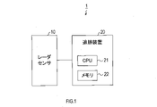
- FIG. 1 is a block diagram showing the configuration of a radar system
- FIG. FIG. 4 is an explanatory diagram showing an overview of processing by a PMB filter
- FIG. 10 is an explanatory diagram showing that the number of hypotheses to be processed increases sharply when there are many tracers and observation points
- FIG. 4 is an explanatory diagram showing hypotheses to be processed in an FMB filter
- FIG. 4 is an explanatory diagram showing an overview of processing by an FMB filter
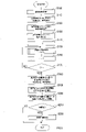
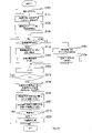
- 4 is a flowchart showing tracking processing in the first embodiment
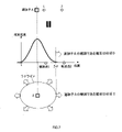
- FIG. 5 is an explanatory diagram showing how to set the search range
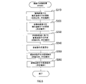
- 6 is a flow chart showing tracer update processing in the first embodiment.
- FIG. 10 is an explanatory diagram illustrating how the state distribution changes due to the tracer update process when Gaussian distribution is used as the state distribution;
- FIG. 10 is a graph showing the result of calculating the calculation time required for tracking processing by simulation, in comparison with the result of the conventional method;
- FIG. 7 is a graph showing the results of calculating the computation time for each type of processing in comparison with the results of the conventional method;
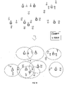
- FIG. 4 is an explanatory diagram showing grouping of tracers using search ranges;
- FIG. 4 is an explanatory diagram showing hypotheses to be considered in tracers with no overlapping search ranges;
- 11 is a flowchart showing tracking processing in the third embodiment;
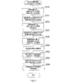
- FIG. 12 is a flowchart showing tracer update processing in the third embodiment;
- FIG. FIG. 10 is an explanatory diagram illustrating how the state distribution changes due to tracer processing when a mixed Gaussian distribution
- the radar system 1 of this embodiment is mounted on a vehicle and used to detect various targets existing around the vehicle on which the radar system 1 is mounted.
- the radar system 1 includes a radar sensor 10 and a tracking device 20.
- the radar sensor 10 uses a LiDAR that irradiates a detection area with laser light and receives reflected light to generate position information of an observation point representing the point where the laser light is reflected.
- LiDAR is an abbreviation for Light Detection and Ranging.
- the radar sensor 10 is not limited to the LiDAR, and may be a millimeter wave radar, an ultrasonic radar, or the like as long as the position information of the observation point can be obtained.
- the detection area is set in front of the vehicle, for example. However, the detection area is not limited to the front of the vehicle. Or a plurality may be set. If there are multiple detection areas, the radar sensor 10 may be provided for each detection area.
- the detection areas may be set so as not to overlap each other, or may be set so that the detection areas partially overlap each other.
- the detection area range is defined by a horizontal angular range ⁇ h and a vertical angular range ⁇ v.
- the radar sensor 10 scans the detection area with an angular resolution ⁇ h in the horizontal direction and an angular resolution ⁇ in the vertical direction. That is, the radar sensor 10 irradiates the detection area with ( ⁇ h/ ⁇ h) ⁇ ( ⁇ v/ ⁇ v) light beams in each preset processing cycle, and samples each light beam a predetermined number of times.
- the sampling interval is set to satisfy the specified range resolution ⁇ R. That is, the radar sensor 10 performs sampling in one second the number of times obtained by dividing the time required for the light to reciprocate the maximum detected distance Rmax by the sampling interval (that is, 2 ⁇ Rmax/c/ ⁇ R times).
- a peak having a signal intensity equal to or higher than the peak threshold is extracted, and the sampling timing (that is, distance) of the peak and the horizontal angle and vertical angle of the irradiated ray are used. to generate the position information of the observation point.
- the peak threshold is set to obtain the desired S/N.
- the position information does not necessarily have to be expressed in a three-dimensional polar coordinate system using distance, horizontal angle, and vertical angle, and may be expressed in a three-dimensional orthogonal coordinate system.
- the tracking device 20 comprises a microcomputer having a CPU 21 and semiconductor memory such as RAM, ROM, flash memory (hereinafter referred to as memory 22). Tracking device 20 may include a co-processor.
- the tracking device 20 executes at least tracking processing by causing the CPU 21 to execute a program stored in the memory 22 .
- target information which is information about targets existing within the detection area, is generated.
- Driving assistance includes, for example, following distance control (ACC), lane keeping assistance (LKA), lane change assistance (LCA), lane departure warning, overtaking assistance, intervention control, automatic braking, and automatic including driving.
- ACC is an abbreviation for Auto Cruise Control
- LKA is an abbreviation for Lane Keeping Assist
- LCA is an abbreviation for Lane Change Assist.
- FMB FMB filter
- PNB PMB filter
- the position of the target is used as the state of the target to be estimated.
- the state of the target to be estimated is not limited to the position.
- two observation points are obtained while two targets are being tracked by the tracers A and B will be described as an example.
- the seven hypotheses are K1 (view 1, view 2), K2 (not, view 2), K3 (view 1, view 1), K4 (view 2, view 1), K5 (not, view 1), K6 (view View 2, not yet), K7 (not yet, not yet).
- the state distribution and the hypothesis likelihood are calculated for each of the hypotheses K1 to K7, and the state distributions of all the hypotheses K1 to K7 are convoluted using the calculated hypothesis likelihoods to obtain the hypotheses K1 to K7 integrate into one.
- the state distribution is a distribution stochastically representing the state (that is, position) of the tracer. Gaussian distribution is used for the state distribution, for example.
- the state distribution is calculated by updating the state distribution obtained in the previous processing cycle using an extended Kalman filter (hereinafter referred to as EKF) or the like based on observation information obtained by observation. However, for each hypothesis, an updated state distribution is generated assuming that each hypothesis is correct with respect to the state distribution obtained in the previous processing cycle.
- EKF extended Kalman filter
- the hypothesis likelihood is a value representing the plausibility of the hypothesis of interest.
- the hypothetical likelihood is calculated from the proximity of the tracer to the observation point, the error of the sensor used for observation, the probability of detection, the probability of false detection, the existence probability of the tracer in the previous processing cycle, and the like.
- Equation (1) the number of hypotheses to be considered in PMB, Knum, is given by equation (1).
- the tracer of interest is always assigned the nearest neighbor observation point, and the likelihood of hypotheses 4 to 6 that the tracer is assigned an observation point other than the nearest neighbor is always close to 0.
- the hypotheses that need to be considered for each tracer are only two patterns, whether it was observed at the nearest observation point or not. That is, the number Knum of hypotheses to be considered is reduced from the number calculated by the formula (1) to 2n.
- the tracking process is executed by the radar sensor 10 every time it takes to scan the entire detection area (hereinafter referred to as a processing cycle).
- observation information representing observation results from the radar sensor 10.
- the observation information includes all observation points whose signal strength exceeds the threshold (hereinafter referred to as observation point group) in the detection area.
- the tracking device 20 sets the number of tracers generated up to the previous processing cycle (hereinafter, existing tracers) as n, and performs existing tracking in the current processing cycle for each of the existing tracers T1 to Tn. Predict child state distributions. Further, the tracking device 20 calculates the existence probability of the target associated with the existing tracer Ti for each of the existing tracers T1 to Tn according to the formula (2).
- k ⁇ 1 is the existence probability of the existing tracer after prediction
- k ⁇ 1 is the existence probability of the existing tracer before prediction
- Ps is a constant representing the survival probability of the target. , and values less than one but close to one are used.
- the state distribution prediction uses the method used in EKF.
- the state distribution is represented by a Gaussian distribution.
- the position of the peak in the state distribution of the tracer in the previous processing cycle (that is, the average value of the state distribution) is moved by the elapsed time of one cycle according to the speed information of the tracer.
- the spread of the state distribution (that is, the variance of the Gaussian distribution) is diffused by the elapsed time of one cycle to obtain the predicted value of the state distribution (hereinafter referred to as the predicted distribution).
- the tracking device 20 sets a search range in which the distance from the position indicated by the average value of the prediction distribution is equal to or less than the upper limit distance for each of the existing tracers T1 to Tn. Mahalanobis distance is used as the distance. However, other distances such as Euclidean distance may be used.
- the tracking device 20 exclusively assigns observation points belonging to the observation point group to each of the existing tracers T1 to Tn. Specifically, among the observation points existing within the search range set for the focused existing tracer, the closest observation point to the center of the searched range is assigned to the focused existing tracer. This process is also called gating. As a result of gating, each extant tracer is assigned at most one observation point. Also, each observation point may or may not be assigned to any one extant tracer.
- the upper limit distance that defines the search range for example, as shown in FIG. 7, a distance corresponding to 5 ⁇ in Gaussian distribution is used. In the Gaussian distribution, the existence probability is almost 0 in the range outside 5 ⁇ . However, in order to suppress erroneous detection, the upper limit distance may be set smaller than 5 ⁇ . In other words, as the upper limit distance is increased, the non-detection probability decreases even though it exists. False positive probability increases. Conversely, the smaller the upper limit distance, the higher the non-detection probability but the lower the false detection probability.
- the tracking device 20 sets 1 to an identifier i that identifies the existing tracers T1 to Tn.
- the tracking device 20 executes a tracer update process for updating the state distribution of the existing tracer Ti.
- the tracking device 20 updates the state of the existing tracer Ti based on the hypothesis (hereinafter, detection hypothesis) that the observation point assigned to the existing tracer Ti observed the existing tracer Ti. do. Specifically, the state distribution of the existing tracer Ti is updated by the EKF, and the existence probability rr_det of the target associated with the existing tracer Ti is updated according to the equation (3).
- the tracking device 20 detects the state of the existing tracer Ti based on the hypothesis that the observation point assigned to the existing tracer Ti does not observe the existing tracer Ti (hereinafter referred to as the undetected hypothesis). to update.
- the predicted distribution calculated in S210 is used as the estimated distribution of the existing tracer Ti, and the existence probability rr mis of the target associated with the existing tracer Ti is updated according to the equation (4).
- Pd represents the detection probability of the radar sensor 10, that is, the probability that an existing target can be detected.
- the detection probability Pd is a constant determined by the performance of the radar sensor 10 . Note that undetected includes the case where the target corresponding to the existing tracer Ti does not exist in the first place, and the case where the object corresponding to the existing tracer Ti exists but is not detected by the radar sensor 10. Equation (4) shows the probability of the latter case.
- the tracking device 20 generates a new tracer based on the undetected hypothesis. Specifically, the tracking device 20 generates a state distribution of the new tracer with the position of the observation point as the mean of the distribution and the error variance of the radar sensor 10 as the variance of the distribution. Further, the tracking device 20 calculates the existence probability rr new of the target associated with the new tracker according to the formula (5).
- D new is a burst rate, and represents how many observation points are detected per sample in one light beam with respect to a plurality of light beams irradiated in a determined azimuth within the scanning range.
- C represents the erroneous detection probability of the radar sensor 10, that is, the probability of detecting a target that does not actually exist, and is also called a clutter rate. Both the burst rate D new and the false positive probability C are constants determined experimentally.
- the tracking device 20 calculates the hypothesis likelihood W 1 of the detection hypothesis and the hypothesis likelihood W 2 of the undetected hypothesis. Specifically, the hypothesis likelihood WD 1 before normalization regarding the detected hypothesis is calculated by the formula (6), and the hypothesis likelihood WD 2 before normalization regarding the undetected hypothesis is calculated by the formula (7). . Furthermore, by normalizing the hypothetical likelihoods WD 1 and WD 2 using equations (8) and (9), hypothetical likelihoods W 1 and W 2 with a total value of 1 are calculated.
- the tracking device 20 updates the state distribution by integrating the two hypotheses generated for the existing tracer Ti. Specifically, the state distribution p(i) of the existing tracer Ti is generated according to the equation (10), and the existence probability r of the target associated with the existing tracer Ti is calculated according to the equation (11).
- the averages ⁇ 1 and ⁇ 2 of two state distributions based on two hypotheses are synthesized using hypothetical likelihoods W 1 and W 2 (that is, folding ) value is the mean of the distribution in the updated state distribution p(i).
- the value obtained by synthesizing (that is, convoluting) the variances P 1 and P 2 of the two hypothetical distributions using the hypothetical likelihoods W 1 and W 2 is the distribution of the updated state distribution p(i). disperse.
- the tracking device 20 integrates the existence probabilities of the new tracers generated in S330 according to formula (12), and ends the tracer update process.
- the tracking device 20 increments the identifier i in the following S160.
- the tracking device 20 determines whether the identifier i is greater than the number n of existing tracers. If i>n, the tracking device 20 assumes that the tracer update process has been executed for all existing tracers, and shifts the process to S180, and if i ⁇ n, the tracer update process is executed. Since there is an existing tracer that has not been updated, the process returns to S150.
- the tracking device 20 generates new tracers based on each of the observation points satisfying the generation conditions, with the fact that the existing tracers T1 to Tn were not assigned in S130 as a generation condition. . Specifically, the tracking device 20 generates a state distribution of the new tracer represented by a Gaussian distribution in which the position of the observation point is the average of the distribution and the error variance of the radar sensor 10 is the variance of the distribution. Further, the tracking device 20 calculates the existence probability of the target associated with the new tracker according to the formula (5).
- the tracking device 20 calculates the existence probability of the target associated with the tracers among the existing tracers T1 to Tn inherited from the previous processing cycle and the new tracers generated in the current processing cycle. Eliminate tracers whose r is less than or equal to the tracer pruning threshold.
- the tracer pruning threshold is set according to the processing capability of the tracking device 20 so that the number of tracers propagated to the next processing cycle is within the number that can be processed by the tracking device 20 .
- the tracking device 20 extracts, from among the tracers remaining without being erased in S190, those tracers for which the existence probability r of the target associated with the tracer is equal to or greater than the target threshold, A target associated with each of the extracted tracers is recognized as an existing target.
- the tracking device 20 determines whether or not there is a target recognized as existing in S200 (hereinafter referred to as a recognition target), and if there is a recognition target, the process proceeds to S220, If there is no recognition target, the processing ends.
- a recognition target a target recognized as existing in S200
- the tracking device 20 uses the information of the tracer associated with the recognition target to generate target information, which is information related to the recognition target, and ends the process.
- Target information includes at least position information.
- S100 corresponds to the information acquisition unit in the present disclosure
- S110 corresponds to the state prediction unit in the present disclosure
- S120 corresponds to the range setting unit in the present disclosure
- S180 corresponds to the tracer generation unit in the present disclosure
- S190 corresponds to the tracer pruning unit in the present disclosure
- S130 corresponds to the observation allocation unit in the present disclosure.
- S310 to S320 correspond to the hypothesis generating section in the present disclosure
- S340 to S350 correspond to the hypothesis integrating section in the present disclosure
- S110, S150, and S180 correspond to the judgment value generating section in the present disclosure.
- the existing tracer to which the observation point is assigned corresponds to the target tracer in the present disclosure
- the observation point assigned to the target tracer corresponds to the target observation point in the present disclosure
- the target tracking A target associated with a child corresponds to a target target in the present disclosure.
- a detected hypothesis corresponds to the first hypothesis in the present disclosure
- an undetected hypothesis corresponds to the second hypothesis in the present disclosure.
- the two hypotheses generated for the extant tracer Ti correspond to the hypothesis group in this disclosure.
- the tracking device 20 generates two hypotheses, a detected hypothesis and an undetected hypothesis, for one observation point assigned to the existing tracer Ti for each existing tracer Ti.
- the number of hypotheses about how to assign observation points is 2n, and the number of hypotheses handled in tracking processing is greatly reduced compared to PMB, in which the number of hypotheses increases exponentially with respect to the number of existing tracers n. can.
- the calculation load of the hypothesis likelihood which needs to be calculated for each hypothesis, is the heaviest, so reducing the number of hypotheses can significantly reduce the calculation load. As a result, it is possible to realize tracking processing with a low load compared to PMB and high performance compared to NN that does not consider undetected hypotheses.
- the tracking device 20 updates the existence probability of the target associated with the existing tracer Ti using the hypothesis likelihood. Therefore, it is possible to improve the performance of determining whether the target associated with the existing tracer Ti exists or does not exist (that is, is noise).
- FIG. 10 and FIG. 11 show the calculation results of the calculation time required for tracking processing for each frame by simulation. Simulations were performed for the case of using the FMB corresponding to the present embodiment, the case of using the PMB of the prior art that does not perform hypothesis integration, and the case of using the PHD that is of the prior art and performs hypothesis integration.
- PHD is an abbreviation for Probability Hypothesis Density.
- the simulation conditions are, as shown in FIG. Both the angular resolution and the angular resolution in the vertical direction were set to 0.1°. That is, the number of light beams used for scanning is 194 in the horizontal direction and 13 in the vertical direction.
- the sampling interval for A/D conversion for each light beam was set to a time corresponding to a distance resolution of 1.9 m, the maximum detection distance was set to 250 m, and the number of samples per light beam was set to 132.
- the applicable range of this process is set to 103.2 m to 131.7 m, the maximum number of samples within the applicable range is set to 37364, and the assumed amount of noise is set to 306.
- FMB significantly reduces the calculation time for hypothesis generation and update compared to PMB. I understand. In addition, it can be seen that FMB has substantially the same overall computation time as PHD, but the pruning computation time is reduced.
- S110 corresponds to prediction, S120 to gating, S130 to hypothesis generation, S150 to update, and S190 to pruning.
- FMB is applied to all tracers.
- the second embodiment differs from the first embodiment in that PMB is applied to tracers in which combinatorial explosion does not occur.
- the tracking device 20 performs the same processing as in the first embodiment.
- the tracking device 20 initializes to 1 the identifier i used for identifying the existing tracers T1 to Tn.
- the tracking device 20 determines whether or not the search range of the existing tracer Ti overlaps with the search range of another tracer. If not, the process proceeds to S152. For example, when tracers A to H and observation points 1 to 18 are located as shown in FIG. C and H are determined to have no overlapping search ranges.
- the tracking device 20 assigns the nearest observation point existing within the search range of the existing tracer Ti to the existing tracer Ti. For example, in FIG. 14, “view 1” for tracer A, “view 2” for tracer B, “view 8” for tracer D, “view 10” for tracer E, and “view 10” for tracer F. is assigned “view 12", and tracer G is assigned “view 14".
- the tracking device 20 executes the tracer update process as in the case of the first embodiment, and advances the process to S160.
- the tracking device 20 assigns all observation points existing within the search range set for the existing tracer Ti to the existing tracer Ti. For example, in FIG. 14, tracer C is assigned “Kan 3”, “Kan 4”, “Kan 5” and “Kan 6”, and tracer H is assigned “Kan 15” and “Kan 16”.
- the tracking device 20 executes tracer update processing using the PMB, and advances the processing to S160.
- the number of generated hypotheses is m+1, where m is the number of assigned observation points.
- m is the number of assigned observation points.
- S142 corresponds to the sorting unit in the present disclosure
- S144 corresponds to the observation allocation unit in the present disclosure
- S152 to S154 correspond to the precise update unit in the present disclosure.
- Gaussian distribution is used as the state distribution of the tracer.
- the third embodiment differs from the first embodiment in that mixed Gaussian distributions are used instead of Gaussian distributions.
- the tracking device 20 performs the same processing as in the first embodiment.
- the tracking device 20 updates the likelihood of each local maximum value (hereinafter, mixed likelihood) included in the state distribution using equation (13). .
- the mixed likelihood calculated in the above processing cycle that is, the mixed likelihood before prediction is used as it is as the mixed likelihood in the prediction distribution.
- j in equation (13) is an identifier for identifying a local maximum existing in the state distribution (that is, individual Gaussian distribution peaks forming the mixed Gaussian distribution).
- m be the number of local maxima that exist in the state distribution.
- the tracking device 20 performs the same processing as in the first embodiment.
- the tracking device 20 executes a tracer update process using the Gaussian mixture distribution as the state distribution.
- the tracking device 20 performs the same processing as in the first embodiment.
- the tracking device 20 calculates the likelihood of each local maximum value in the state distribution (that is, hypothesis distribution) updated with the detection hypothesis using equations (14) and (15).
- Equation (15) means normalizing each mixed likelihood such that the total value of mixed likelihoods of a plurality of local maxima belonging to the same prediction distribution is one.
- the tracking device 20 performs the same processing as in the first embodiment.
- the tracking device 20 uses the prediction distribution as it is as the state distribution after updating (that is, the hypothesis distribution), and the mixed likelihood of each local maximum value in the hypothesis distribution is calculated as (16) Calculate using the formula.
- the mixed likelihood of the hypothetical distribution based on the undetected hypothesis is also used as is the mixed likelihood of the predicted distribution calculated in S115.
- the tracking device 20 performs the same processing as in the first embodiment.
- the tracking device 20 integrates the hypotheses generated for the existing tracer Ti. Specifically, the updated state distribution p(i) of the existing tracer Ti is generated according to the equation (17), and the existence probability r of the target associated with the existing tracer Ti is calculated according to the equation (18). do.
- Equation (17) is such that, as shown in FIG. 18, the updated state distribution is m Gaussian distributions that individually represent each local maximum value in the hypothesis distribution of the detection hypothesis and each local maximum value in the hypothesis distribution of the undetected hypothesis. This means that the m Gaussian distributions that individually represent are simply added together. Equation (18) is the same as Equation (11).
- the tracking device 20 calculates the mixed likelihood of each local maximum in the state distribution updated in S350 using equations (19) and (20).
- Equation (19) is the mixed likelihood of maximum values based on the hypothesis distribution of the detected hypothesis
- Equation (20) is the mixed likelihood of each maximum value based on the hypothesis distribution of the undetected hypothesis. That is, in the present embodiment, each time the tracking update process is performed, the number of local maximum values included in the state distribution after update is double the number of local maximum values included in the state distribution before update.
- the tracking device 20 executes the same processing as in the first embodiment, and terminates the tracer update processing.
- the tracking device 20 performs the same processes as in the first embodiment in subsequent S160 to S190.
- the tracking device 20 deletes the maximal value in the state distribution updated in S155 whose mixed likelihood is equal to or less than the maximal value pruning threshold. Furthermore, for a state distribution in which even one maximum value has been eliminated, the tracking device 20 calculates the mixed likelihood of each maximum value in the state distribution so that the sum of the mixed likelihoods becomes 1 (that is, normalized recalculate as
- the tracking device 20 executes the same processing as in the first embodiment, and ends the tracking processing.
- S354 corresponds to the mixed likelihood calculation unit in the present disclosure
- S195 corresponds to the local maximum value pruning unit in the present disclosure.
- the mixed likelihood is calculated for each local maximum contained in the state distribution, and the local maximum where the mixed likelihood is equal to or less than the local maximum value pruning threshold is removed, so the state distribution becomes unnecessarily complicated. Therefore, it is possible to suppress an increase in computational load due to an increase in the number of local maximum values.
- the position of the observation point is used as the state to be updated by the tracking process, but the present disclosure is not limited to the position of the observation point. Any information obtained from the target, such as acceleration, may be used.
- the state of the tracer is updated using the PMB filter, but the state of the tracer is updated by filters other than the PMB filter used in the theory of RFS, such as PHD filter, LMB A filter, a PMBM filter, or the like may be used.
- PHD filter labeled Multi-Bernoulli
- PMBM Poisson Multi-Bernoulli Mixture.
- the presence probability represented by a value of 0 to 1 is used as the presence determination value used to determine whether or not there is a target associated with the tracer, but the present disclosure is not limited to the existence probability.
- radix information that allows a value of 1 or more may be used as the presence determination value.
- the tracking device 20 and techniques described in this disclosure may be provided by configuring a processor and memory programmed to perform one or more functions embodied by a computer program. It may be implemented by a computer. Alternatively, the tracking device 20 and techniques described in this disclosure may be implemented by a dedicated computer provided by configuring the processor with one or more dedicated hardware logic circuits. Alternatively, the tracking device 20 and techniques described in this disclosure are a combination of a processor and memory programmed to perform one or more functions and a processor configured by one or more hardware logic circuits. may be implemented by one or more dedicated computers configured by Computer programs may also be stored as computer-executable instructions on a computer-readable non-transitional tangible storage medium. The method of realizing the function of each part included in the tracking device 20 does not necessarily include software, and all the functions may be realized using one or more pieces of hardware.
- a plurality of functions possessed by one component in the above embodiment may be realized by a plurality of components, or a function possessed by one component may be realized by a plurality of components. . Also, a plurality of functions possessed by a plurality of components may be realized by a single component, or a function realized by a plurality of components may be realized by a single component. Also, part of the configuration of the above embodiment may be omitted. Moreover, at least part of the configuration of the above embodiment may be added or replaced with respect to the configuration of the other above embodiment.
Landscapes
- Engineering & Computer Science (AREA)
- Radar, Positioning & Navigation (AREA)
- Remote Sensing (AREA)
- Physics & Mathematics (AREA)
- Computer Networks & Wireless Communication (AREA)
- General Physics & Mathematics (AREA)
- Electromagnetism (AREA)
- Radar Systems Or Details Thereof (AREA)
- Optical Radar Systems And Details Thereof (AREA)
Abstract
観測割当部は、情報取得部にて取得された観測情報と予測分布が示す観測情報との距離に従って、現存追跡子のそれぞれに、観測点を排他的に割り当てる。仮説生成部は、対象追跡子毎に、第1の仮説及び第2の仮説を含む仮説群に属する仮説のそれぞれについて、仮説尤度、及び仮説分布を生成する。第1の仮説は、対象観測点が対象物標を観測した結果であるとする仮説である。第2の仮説は、対象観測点が対象物標を観測した結果ではないとする仮説である。仮説尤度は、仮説の尤度である。仮説分布は、仮説が正しいと仮定して更新した状態分布である。
Description
本国際出願は、2021年5月12日に日本国特許庁に出願された日本国特許出願第2021-081239号に基づく優先権を主張するものであり、日本国特許出願第2021-081239号の全内容を本国際出願に参照により援用する。
本開示は、物標を追跡する追跡装置に関する。
追跡中の物標候補を表す追跡子の状態を、観測点の情報を用いて逐次更新するトラッキングとして、NNトラッキング、及びRFSトラッキングが知られている。NNは、Nearest Neighborの略であり、RFSは、Random Finite Setの略である。
NNトラッキングでは、追跡子の状態の更新に、追跡子に最も近い1つの観測点の情報を用いる。RFSトラッキングでは、RFS追跡子から一定の範囲内にあるすべての観測点の情報を用いる。RFSトラッキングは、例えば、特許文献1に開示されている。
RFSトラッキングでは、複数の観測点それぞれの検知確率と、複数の追跡子それぞれの存在確率を用いて、複数の追跡子と複数の観測点との対応関係を表す複数の仮説を生成し、各仮説の尤度演算を行い、すべての仮説を考慮したトラッキングが実行される。また、各仮説に従って更新される追跡子の状態を、各仮説の尤度を用いて畳み込むことで、次回の処理サイクルに伝搬する仮説の数を削減する手法も知られている。
しかしながら、発明者の詳細な検討の結果、以下の課題が見出された。すなわち、RFSトラッキングでは、観測点や追跡子の数が増加するに従って仮説の数、ひいてはトラッキングに要する演算量、特に仮説の尤度の算出に要する演算量が指数関数的に増大する。従って、RFSトラッキングは、リアルタイムでの処理が要求される車載の追跡装置等への適用が困難であった。
本開示の1つの局面は、トラッキングの精度を維持しつつ演算量を抑制する技術を提供する。
本開示の1つの局面は、追跡装置であって、情報取得部と、追跡子生成部と、状態予測部と、状態更新部と、を備える。
情報取得部は、処理サイクル毎に、車両の周囲に存在する物標の状態を観測するセンサから観測情報を取得するように構成される。追跡子生成部は、情報取得部により観測情報が取得された1つ以上の観測点である観測点群のうち、予め設定された生成条件を満たす観測点について、観測情報の状態を確率的に示した状態分布を有する追跡子を生成するように構成される。状態予測部は、前回の処理サイクルまでに生成された追跡子である現存追跡子のそれぞれについて、現存追跡子が有する状態分布から、現存追跡子の今回の処理サイクルでの観測情報の状態を予測した状態分布である予測分布を生成するように構成される。状態更新部は、現存追跡子のそれぞれについて、状態予測部にて生成された予測分布、及び今回の処理サイクルで得られた観測点群の観測情報を用いて、現存追跡子が有する状態分布を更新するように構成される。
また、状態更新部は、観測割当部と、仮説生成部と、を備える。
観測割当部は、情報取得部にて取得された観測情報と予測分布が示す観測情報との距離に従って、現存追跡子のそれぞれに、観測点を排他的に割り当てるように構成される。仮説生成部は、対象追跡子毎に、第1の仮説、及び第2の仮説を含む仮説群に属する仮説のそれぞれについて、仮説の尤度である仮説尤度、及び仮説が正しいと仮定して更新した状態分布である仮説分布を生成するように構成される。第1の仮説は、対象観測点が対象物標を観測した結果であるとする仮説である。第2の仮説は、対象観測点が対象物標を観測した結果ではないとする仮説である。対象追跡子は、観測割当部により観測点が割り当てられた現存追跡子である。対象観測点は、対象追跡子に割り当てられた観測点である。対象物標は、対象追跡子に対応づけられる物標である。
このような構成によれば、一つの観測点が複数の追跡子に割り当てられることがないため、追跡子と観測点との組み合わせの数、すなわち仮説の数が削減され、追跡処理の演算負荷を軽減できる。
以下、図面を参照しながら、本開示の実施形態を説明する。
[1.第1実施形態]
[1-1.構成]
本実施形態のレーダシステム1は、車両に搭載され、当該レーダシステム1を搭載する車両の周囲に存在する種々の物標を検出するために用いられる。
[1-1.構成]
本実施形態のレーダシステム1は、車両に搭載され、当該レーダシステム1を搭載する車両の周囲に存在する種々の物標を検出するために用いられる。
図1に示すように、レーダシステム1は、レーダセンサ10と、追跡装置20とを備える。
レーダセンサ10は、検知エリアにレーザ光を照射し、反射光を受光することで、レーザ光を反射した点を表す観測点の位置情報を生成するLiDARが用いられる。LiDARは、Light Detection and Rangingの略である。但し、レーダセンサ10は、LiDARに限定されるものではなく、観測点の位置情報が得られればよく、ミリ波レーダ、超音波レーダ等であってもよい。
検知エリアは、例えば車両の前方に設定される。但し、検知エリアは、車両の前方に限定されるものではなく、車両の後方、右側方、左側方、右前方、右後方、左前方、左後方のいずれかが検知エリアとなるように一つ又は複数設定されてもよい。検知エリアが複数存在する場合、検知エリア毎にレーダセンサ10を備えてもよい。各検知エリアは互いに重なり合うことがないように設定されてもよいし、検知エリアの一部が互いに重なり合うように設定されてもよい。検知エリアの範囲は、水平角度範囲θh及び垂直角度範囲θvによって規定される。
レーダセンサ10は、検知エリア内を、水平方向には角度分解能Δθh、垂直方向には角度分解能Δθで走査する。すなわち、レーダセンサ10は、予め設定された処理サイクル毎に、検知エリア内に、(θh/Δθh)×(θv/Δθv)本の光線を照射し、光線毎に所定回のサンプリングを実施する。サンプリング間隔は、指定された距離分解能ΔRを満たすように設定される。つまり、レーダセンサ10は、最大検距離Rmaxを光が往復するのに要する時間を、サンプリング間隔で除した回数(すなわち、2×Rmax/c/ΔR回)のサンプリングを1秒間に実行する。
そして、光線毎にサンプリングされた値によって示される波形から、ピーク閾値以上の信号強度を有するピークを抽出して、そのピークのサンプリングタイミング(すなわち距離)、照射した光線の水平角度及び垂直角度を用いて、観測点の位置情報を生成する。ピーク閾値は、所望のS/Nが得られるように設定される。位置情報は、必ずしも、距離、水平角度、垂直角度を用いた3次元の極座標系で表されている必要はなく、3次元の直交座標系で表されてもよい。
追跡装置20は、CPU21と、RAM、ROM、フラッシュメモリ等の半導体メモリ(以下、メモリ22)とを有するマイクロコンピュータを備える。追跡装置20は、コプロセッサを備えてもよい。
追跡装置20は、CPU21がメモリ22に記憶されたプログラムを実行することで、少なくとも追跡処理を実行する。
追跡処理は、レーダセンサ10から得られる観測点の位置情報に基づいて、検知エリア内に存在する物標に関する情報である物標情報を生成する。
追跡処理によって生成された物標情報は、運転支援のために実施される種々の処理や、レーダセンサ10の軸ずれを推定する処理等に用いられる。運転支援には、例えば、車間距離制御(以下、ACC)、車線維持支援(以下、LKA)、車線変更支援(以下、LCA)、車線逸脱警報、追越支援、介入制御、自動制動、及び自動運転等が含まれる。ACCは、Auto Cruise Controlの略であり、LKAは、Lane Keeping Assistの略であり、LCAはLane Change Assistの略である。
[1-2.トラッキングの概要]
追跡処理にて採用するRFSトラッキングの一種であるFMBフィルタを用いた処理(以下、FMB)の概要について説明する。FMBは、PMBフィルタを用いた既存の処理(以下、PNB)を改良して処理を高速化した手法である。FMBは、Fast Multi-Bernoulliの略であり、PMBは、Poisson Multi-Bernoulliの略である。
追跡処理にて採用するRFSトラッキングの一種であるFMBフィルタを用いた処理(以下、FMB)の概要について説明する。FMBは、PMBフィルタを用いた既存の処理(以下、PNB)を改良して処理を高速化した手法である。FMBは、Fast Multi-Bernoulliの略であり、PMBは、Poisson Multi-Bernoulliの略である。
ここでは、推定する物標の状態として、物標の位置を用いる。但し、推定する物標の状態は、位置に限られるものではない。また、ここでは、理解を容易にするため、2つの物標を追跡子A,Bで追跡中に、2つの観測点が得られた場合を例にして説明する。
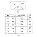
RFSトラッキングでは、図2に示すように、2つの追跡子A,Bと2つの観測点との組み合わせを表す7個の仮説が考慮される。すなわち、仮説iをKi(追跡子Aを観測した観測点,追跡子Bを観測した観測点)で表し、2つの観測点を「観1」,「観2」、いずれの観測点にも対応しない場合を「未」で表すものとする。7個の仮説は、K1(観1,観2)、K2(未,観2)、K3(観1,未)、K4(観2,観1)、K5(未,観1)、K6(観2,未)、K7(未,未)となる。
そして、PMBでは、仮説K1~K7のそれぞれについて、状態分布及び仮説尤度を算出し、算出した仮説尤度を用いて全ての仮説K1~K7の状態分布を畳みこむことで、仮説K1~K7を一つに統合する。なお、状態分布は、追跡子の状態(すなわち、位置)を確率的に表した分布である。状態分布には、例えば、ガウス分布が用いられる。状態分布は、観測によって得られる観測情報に基づき拡張カルマンフィルタ(以下、EKF)等を用いて前回の処理サイクルで得られた状態分布を更新することで算出される。但し、前回の処理サイクルで得られた状態分布に対して、仮説毎に、各仮説が正しいと仮定して更新された状態分布がそれぞれ生成される。仮説尤度は、着目する仮説のもっともらしさを表す値である。仮説尤度は、追跡子から観測点までの近さ、観測に用いたセンサの誤差、検知確率、誤検知確率、前回の処理サイクルでの追跡子の存在確率等から算出される。
次に、前述の処理を、n個の追跡子で物標を追跡中に、n個の観測が得られた場合に一般化すると、PMBにおいて考慮すべき仮説の数Knumは、(1)式で表される。

そこで、FMBでは、追跡の対象となる路上障害物は「静止」しており、予測不能な動きをしないこと、及び、LiDARの測距精度は極めて高いが、未検知及び誤検知は無視できない程度に発生することを前提とする。
前述の前提の下では、図4に示すように、着目する追跡子には、必ず最近傍の観測点が割り当てられ、追跡子に最近傍の観測点以外が割り当てられる仮説4~6の尤度は、必ず0に近い値となる。
すると、図5に示すように、追跡子毎に考慮が必要な仮説は、最近傍の観測点にて観測されたか、観測されなかったかの2パターンのみとなる。つまり、考慮すべき仮説の数Knumは、(1)式で算出される数から2n個に減少する。
[1-3.処理]
次に、追跡装置20が実行する追跡処理について、図6のフローチャートを用いて説明する。
次に、追跡装置20が実行する追跡処理について、図6のフローチャートを用いて説明する。
追跡処理は、レーダセンサ10にて、検知エリア全体の走査に要する時間(以下、処理サイクル)毎に実行される。
追跡処理が開始されると、S100では、追跡装置20は、レーダセンサ10から観測結果を表す観測情報を取得する。観測情報には、検知エリアの中で、信号強度が閾値を超えるすべての観測点(以下、観測点群)が含まれる。
続くS110では、追跡装置20は、前回の処理サイクルまでに生成された追跡子(以下、現存追跡子)の数をnとして、現存追跡子T1~Tnのそれぞれについて、今回の処理サイクルにおける現存追跡子の状態分布を予測する。更に、追跡装置20は、現存追跡子T1~Tnのそれぞれについて、現存追跡子Tiに対応づけられる物標の存在確率を、(2)式に従って算出する。

状態分布の予測は、EKFで使用される手法を用いる。なお、状態分布は、ガウス分布で表される。EKFでは、前回の処理サイクルでの追跡子の状態分布におけるピークの位置(すなわち、状態分布の平均値)を、追跡子が持つ速度情報に従って、1サイクルの時間経過分だけ移動させる。更に、EKFでは、状態分布の広がり(すなわち、ガウス分布の分散)を、1サイクルの時間経過分だけ拡散させることで、状態分布の予測値(以下、予測分布)が得られる。
続くS120では、追跡装置20は、現存追跡子T1~Tnのそれぞれについて、予測分布の平均値が示す位置からの距離が上限距離以下となる探査範囲を設定する。距離は、マハラノビス距離を用いる。但し、ユークリッド距離等、その他の距離を用いてもよい。
続くS130では、追跡装置20は、現存追跡子T1~Tnのそれぞれに、観測点群に属する観測点を排他的に割り当てる。具体的には、着目する現存追跡子について設定された探査範囲内に存在する観測点のうち、探査範囲の中心に最も近い観測点を、着目する現存追跡子に割り当てる。この処理をゲーティングともいう。ゲーティングの結果、各現存追跡子には、最大で1つの観測点が割り当てられる。また、各観測点は、いずれか1つの現存追跡子に割り当てられる場合と、いずれの現存追跡子にも割り当てられない場合とがある。
探査範囲を規定する上限距離は、例えば、図7に示すように、ガウス分布において5σに相当する距離を用いる。なお、ガウス分布において5σより外側の範囲では、存在確率がほぼ0となる。但し、誤検知を抑制するために、上限距離を5σより小さく設定してもよい。つまり、上限距離を大きくするほど、存在するにも関わらず検知できない未検知確率は減少するが、着目する現存追跡子に対して、その現存追跡子を観測したものではない観測点が対応づけられる誤検知確率が増大する。逆に、上限距離を小さくするほど、未検知確率は増大するが誤検知確率が減少する。
続くS140では、追跡装置20は、現存追跡子T1~Tnを識別する識別子iを1に設定する。
続くS150では、追跡装置20は、現存追跡子Tiの状態分布を更新する追跡子更新処理を実行する。
ここで、追跡子更新処理の詳細を図8のフローチャートを用いて説明する。追跡子更新処理では、先に説明したFMBが適用される。
S310では、追跡装置20は、現存追跡子Tiに割り当てられた観測点が、現存追跡子Tiを観測したものであるとの仮説(以下、検知仮説)に基づいて現存追跡子Tiの状態を更新する。具体的には、現存追跡子Tiの状態分布を、EKFによって更新し、現存追跡子Tiに対応づけられる物標の存在確率rrdetを(3)式に従って更新する。


続くS330では、追跡装置20は、未検知仮説に基づく新規の追跡子を生成する。具体的には、追跡装置20は、観測点の位置を分布の平均、レーダセンサ10の誤差分散を分布の分散とする新規追跡子の状態分布を生成する。更に、追跡装置20は、新規追跡子に対応付けられる物標の存在確率rrnewを、(5)式に従って算出する。

続くS340では、追跡装置20は、検知仮説の仮説尤度W1、及び未検知仮説の仮説尤度W2を算出する。具体的には、検知仮説に関する正規化前の仮説尤度WD1は、(6)式により算出され、未検知仮説に関する正規化前の仮説尤度WD2は、(7)式により算出される。更に、(8)(9)式により、仮説尤度WD1,WD2を正規化することで、合計値が1となる仮説尤度W1,W2が算出される。


続くS360では、追跡装置20は、S330で生成された新規追跡子の存在確率を、(12)式に従って統合して、追跡子更新処理を終了する。

続くS170では、追跡装置20は、識別子iが現存追跡子の数nより大きいか否かを判定する。追跡装置20は、i>nであれば、全ての現存追跡子に対して追跡子更新処理が実行されたものとして処理をS180に移行し、i≦nであれば、追跡子更新処理が実行されていない現存追跡子が存在するため、処理をS150に戻す。
S180では、追跡装置20は、先のS130にて、現存追跡子T1~Tnに割り当てられなかったことを生成条件とし、生成条件を満たす観測点のそれぞれに基づいて、新規の追跡子を生成する。具体的には、追跡装置20は、観測点の位置を分布の平均、レーダセンサ10の誤差分散を分布の分散とするガウス分布で示される新規追跡子の状態分布を生成する。更に、追跡装置20は、新規追跡子に対応づけられる物標の存在確率を、(5)式に従って算出する。
続くS190では、追跡装置20は、前回の処理サイクルから引き継いだ現存追跡子T1~Tn、及び今回の処理サイクルにて生成された新規追跡子のうち、追跡子に対応づけられる物標の存在確率rが追跡子剪定閾値以下である追跡子を消去する。追跡子剪定閾値は、次回の処理サイクルに伝搬される追跡子の数が、追跡装置20にて処理可能な数に収まるように、追跡装置20の処理能力に応じて設定される。
続くS200では、追跡装置20は、S190にて消去されずに残った追跡子のうち、該追跡子に対応づけられる物標の存在確率rが物標化閾値以上である追跡子を抽出し、該抽出された追跡子のそれぞれに対応づけられる物標を、実在する物標として認識する。
続くS210では、追跡装置20は、S200にて、実在すると認識された物標(以下、認識物標)が有るか否かを判定し、認識物標が有れば処理をS220に移行し、認識物標が無ければ処理を終了する。
S220では、追跡装置20は、認識物標に対応づけられる追跡子の情報を用いて認識物標に関する情報である物標情報を生成して、処理を終了する。物標情報には、少なくとも位置情報が含まれる。
[1-4.用語の対応]
本実施形態において、S100が本開示における情報取得部に相当し、S110が本開示における状態予測部に相当し、S120が本開示における範囲設定部に相当し、S130~S170が本開示における状態更新部に相当する。また、S180が本開示における追跡子生成部に相当し、S190が本開示における追跡子剪定部に相当し、S130が本開示における観測割当部に相当する。更に、S310~S320が本開示における仮説生成部に相当し、S340~S350が本開示における仮説統合部に相当し、S110、S150、S180が本開示における判定値生成部に相当する。なお、S130にて、観測点が割り当てられた現存追跡子が、本開示における対象追跡子に相当し、対象追跡子に割り当てられた観測点が、本開示における対象観測点に相当し、対象追跡子に対応づけられる物標が、本開示における対象物標に相当する。検知仮説が本開示における第1の仮説に相当し、未検知仮説が本開示における第2の仮説に相当する。現存追跡子Tiについて生成される2つの仮説が本開示における仮説群に相当する。
本実施形態において、S100が本開示における情報取得部に相当し、S110が本開示における状態予測部に相当し、S120が本開示における範囲設定部に相当し、S130~S170が本開示における状態更新部に相当する。また、S180が本開示における追跡子生成部に相当し、S190が本開示における追跡子剪定部に相当し、S130が本開示における観測割当部に相当する。更に、S310~S320が本開示における仮説生成部に相当し、S340~S350が本開示における仮説統合部に相当し、S110、S150、S180が本開示における判定値生成部に相当する。なお、S130にて、観測点が割り当てられた現存追跡子が、本開示における対象追跡子に相当し、対象追跡子に割り当てられた観測点が、本開示における対象観測点に相当し、対象追跡子に対応づけられる物標が、本開示における対象物標に相当する。検知仮説が本開示における第1の仮説に相当し、未検知仮説が本開示における第2の仮説に相当する。現存追跡子Tiについて生成される2つの仮説が本開示における仮説群に相当する。
[1-5.効果]
以上詳述した第1実施形態によれば、以下の効果を奏する。
以上詳述した第1実施形態によれば、以下の効果を奏する。
(1a)追跡装置20では、現存追跡子T1~Tnに対して観測点を割り当てるときに、着目する現存追跡子Tiについて設定された探査範囲内に存在する観測点を対象として、最も近い距離にある観測点を割り当てる。つまり、現存追跡子Tiとの距離が遠いため仮説尤度がほぼ0となるような観測点に関する仮説は、生成されることがなく、演算をする前に除去されるため、追跡処理の演算負荷を軽減できる。
(1b)追跡装置20では、現存追跡子Ti毎に、現存追跡子Tiに割り当てられた1つの観測点に対する検知仮説及び未検知仮説の2つの仮説を生成する。つまり、観測点の割り当て方についての仮説数が2n個となり、現存追跡子の数nに対して仮説数が指数関数的に増大するPMBと比較して、追跡処理で扱う仮説数を大幅に削減できる。なお、追跡処理では、仮説毎に算出する必要がある仮説尤度の演算負荷が最も重いため、仮説数を削減することで、演算負荷を大幅に削減できる。その結果、PMBと比較して低負荷で、かつ、未検知仮説を考慮しないNNと比較して高性能な追跡処理を実現できる。
(1c)追跡装置20では、現存追跡子Ti毎に生成される2つの仮説を畳み込みによって統合することで、仮説の数、ひいては追跡子の数を半減させ、更に、現存追跡子及び新規追跡子のうち、存在確率が追跡子剪定閾値以下となる追跡子を削除する。従って、次回の処理サイクルに伝搬される追跡子の数が削減されるため、追跡処理に要する演算負荷を更に軽減できる。
(1d)追跡装置20では、処理サイクル毎に、現存追跡子Tiに対応づけられる物標の存在確率を、仮説尤度を用いて更新する。従って、現存追跡子Tiに対応づけられる物標が実在するか実在しない(すなわち、ノイズである)かの切り分け性能を向上させることができる。
[1-6.実験]
フレーム毎に追跡処理に要する演算時間を、シミュレーションによって算出した結果を図10、図11に示す。シミュレーションは、本実施形態に対応するFMBを用いた場合、従来技術であり仮説統合を行わないPMB、及び従来技術であり仮説統合を行うPHDを用いた場合について実施した。PHDは、Probability Hypothesis Densityの略である。
フレーム毎に追跡処理に要する演算時間を、シミュレーションによって算出した結果を図10、図11に示す。シミュレーションは、本実施形態に対応するFMBを用いた場合、従来技術であり仮説統合を行わないPMB、及び従来技術であり仮説統合を行うPHDを用いた場合について実施した。PHDは、Probability Hypothesis Densityの略である。
シミュレーションの条件は、図12に示すように、観測点の抽出に用いる閾値レベルを2.40σ、水平方向の視野角を19.4°、垂直方向の視野角を1.3°、水平方向の角度分解能及び垂直方向の角度分解能をいずれも0.1°とした。つまり、走査に用いる光線本数は、水平方向に194本、垂直方向に13本となる。各光線においてA/D変換のサンプリング間隔は、距離分解能が1.9mに相当する時間とし、最大検知距離を250mとして、光線一本当たりのサンプリング数を132個とした。また、本処理の適用範囲を103.2m~131.7mの範囲として、適用範囲内の最大サンプル数を37364個、想定雑音量を306個とした。
図10に示すように、FMBを適用した場合、PMBを適用した場合と比較して、演算時間が1/10程度に減少する。また、PHDと比較しても減少することがわかる。
図11に示すように、予測、ゲーティング、仮説生成、更新、剪定に分けて演算時間を測定した結果、FMBでは、PMBと比較して、仮説生成及び更新で大幅に演算時間が削減されることがわかる。また、FMBでは、PHDと比較して、全体的な演算時間が略同様となるが、剪定の演算時間が削減されることがわかる。なお、S110が予測、S120がゲーティング、S130が仮説生成、S150が更新、S190が剪定に相当する。
[2.第2実施形態]
[2-1.第1実施形態との相違点]
第2実施形態は、基本的な構成は第1実施形態と同様であるため、相違点について以下に説明する。なお、第1実施形態と同じ符号は、同一の構成を示すものであって、先行する説明を参照する。
[2-1.第1実施形態との相違点]
第2実施形態は、基本的な構成は第1実施形態と同様であるため、相違点について以下に説明する。なお、第1実施形態と同じ符号は、同一の構成を示すものであって、先行する説明を参照する。
前述した第1実施形態では、すべての追跡子に対してFMBを適用している。第2実施形態では、組み合わせ爆発が生じない追跡子に対してはPMBを適用する点で、第1実施形態と相違する。
[2-2.処理]
次に、第2実施形態の追跡装置20が、図6に示した第1実施形態の追跡処理に代えて実行する追跡処理について、図13のフローチャートを用いて説明する。
次に、第2実施形態の追跡装置20が、図6に示した第1実施形態の追跡処理に代えて実行する追跡処理について、図13のフローチャートを用いて説明する。
S100~S120は、追跡装置20は、第1実施形態の場合と同様の処理を実行する。
続くS140では、追跡装置20は、現存追跡子T1~Tnの識別に用いる識別子iを1に初期化する。
続くS142では、追跡装置20は、現存追跡子Tiの探査範囲は、他の追跡子の探査範囲との重複があるか否かを判定し、重複がある場合は処理をS144に移行し、重複がない場合は、処理をS152に移行する。例えば、図14に示すように、追跡子A~Hと、観測点1~18とが位置する場合、追跡子A,B,D~Gは、探査範囲に重複があると判定され、追跡子C,Hは、探査範囲に重複がないと判定される。
S144では、追跡装置20は、現存追跡子Tiの探査範囲内に存在する直近の観測点を、現存追跡子Tiに割り当てる。例えば、図14では、追跡子Aには「観1」、追跡子Bには「観2」、追跡子Dには「観8」、追跡子Eには「観10」、追跡子Fには「観12」、追跡子Gには「観14」が割り当てられる。
続くS150では、追跡装置20は、第1実施形態の場合と同様に追跡子更新処理を実行して、S160に処理を進める。
S152では、追跡装置20は、現存追跡子Tiについて設定された探査範囲内に存在するすべての観測点を、現存追跡子Tiに割り当てる。例えば、図14では、追跡子Cには「観3」「観4」「観5」「観6」、追跡子Hには「観15」「観16」が割り当てられる。
続くS154では、追跡装置20は、PMBを用いた追跡子更新処理を実行して、処理をS160に進める。
探査範囲が他の追跡子の探査範囲と重複しない追跡子では、図15に示すように、割り当てられた観測点の数をmとすると、生成される仮説の数はm+1個となる。つまり、組み合わせ爆発は生じないため、すべての仮説を考慮するPMBの手法を用いて計算することが可能となる。
以下、S160~S220の処理は、第1実施形態の場合と同様である。
[2-3.用語の対応]
本実施形態において、S142が本開示における振分部に相当し、S144が本開示における観測割当部に相当し、S152~S154が本開示における精密更新部に相当する。
本実施形態において、S142が本開示における振分部に相当し、S144が本開示における観測割当部に相当し、S152~S154が本開示における精密更新部に相当する。
[2-4.効果]
以上詳述した第2実施形態によれば、前述した第1実施形態の効果(1a)~(1d)を奏し、さらに、以下の効果を奏する。
以上詳述した第2実施形態によれば、前述した第1実施形態の効果(1a)~(1d)を奏し、さらに、以下の効果を奏する。
(2a)本実施形態では、探査範囲が他とは重ならないことを条件として、部分的にPMBを適用することで、処理負荷を大幅に増大させることなく、PMBを適用した追跡子に対する追跡処理の精度を向上させることができる。
[3.第3実施形態]
[3-1.第1実施形態との相違点]
第2実施形態は、基本的な構成は第1実施形態と同様であるため、相違点について以下に説明する。なお、第1実施形態と同じ符号は、同一の構成を示すものであって、先行する説明を参照する。
[3-1.第1実施形態との相違点]
第2実施形態は、基本的な構成は第1実施形態と同様であるため、相違点について以下に説明する。なお、第1実施形態と同じ符号は、同一の構成を示すものであって、先行する説明を参照する。
前述した第1実施形態では、追跡子の状態分布としてガウス分布を使用している。第3実施形態では、ガウス分布の代わりに混合ガウス分布を用いる点で、第1実施形態と相違する。
[3-2.処理]
次に、第3実施形態の追跡装置20が、図6に示す第1実施形態の追跡処理に代えて実行する追跡処理について、図16のフローチャートを用いて説明する。
次に、第3実施形態の追跡装置20が、図6に示す第1実施形態の追跡処理に代えて実行する追跡処理について、図16のフローチャートを用いて説明する。
S100では、追跡装置20は、第1実施形態の場合と同様の処理を実行する。
続くS115では、追跡装置20は、第1実施形態のS110の処理に加えて、状態分布に含まれる各極大値の尤度(以下、混合尤度)を、(13)式を用いて更新する。

続くS120~S140では、追跡装置20は、第1実施形態の場合と同様の処理を実行する。
続くS155では、追跡装置20は、状態分布として混合ガウス分布を用いる追跡子更新処理を実行する。
ここで、追跡子更新処理の詳細を図17のフローチャートを用いて説明する。追跡子更新処理では、図8に示した第1実施形態の追跡子更新処理と相違する点について説明する。
S310では、追跡装置20は、第1実施形態の場合と同様の処理を実行する。
続くS315では、追跡装置20は、検知仮説で更新された状態分布(すなわち、仮説分布)における各極大値の尤度を、(14)(15)式を用いて算出する。

続くS320では、追跡装置20は、第1実施形態の場合と同様の処理を実行する。
続くS325では、追跡装置20は、未検知仮説を採用した場合、予測分布をそのまま更新後の状態分布(すなわち、仮説分布)として用い、仮説分布における各極大値の混合尤度を、(16)式を用いて算出する。

続く330~S340では、追跡装置20は、第1実施形態の場合と同様の処理を実行する。
続くS352では、追跡装置20は、現存追跡子Tiについて生成された仮説を統合する。具体的には、現存追跡子Tiの更新後の状態分布p(i)を、(17)式に従って生成し、現存追跡子Tiに対応づけられる物標の存在確率rを(18)式に従って算出する。

続くS354では、追跡装置20は、S350にて更新された状態分布中の各極大値の混合尤度を、(19)(20)式を用いて算出する。

続くS360では、追跡装置20は、第1実施形態の場合と同様の処理を実行して、追跡子更新処理を終了する。
図16に戻り、追跡子更新処理が終了すると、続くS160~S190では、追跡装置20は、第1実施形態の場合と同様の処理を実行する。
続くS195では、追跡装置20は、S155にて更新された状態分布中において混合尤度が極大値剪定閾値以下となる極大値を消去する。更に、追跡装置20は、一つでも極大値が消去された状態分布については、その状態分布中の各極大値の混合尤度を、混合尤度の合計が1となる(すなわち、正規化される)ように再計算する。
続くS200~S220では、追跡装置20は、第1実施形態の場合と同様の処理を実行して、追跡処理を終了する。
[3-3.用語の対応]
本実施形態において、S354が本開示における混合尤度算出部に相当し、S195が本開示における極大値剪定部に相当する。
本実施形態において、S354が本開示における混合尤度算出部に相当し、S195が本開示における極大値剪定部に相当する。
[3-4.効果]
以上詳述した第3実施形態によれば、前述した第1実施形態の効果(1a)~(1d)を奏し、さらに、以下の効果を奏する。
以上詳述した第3実施形態によれば、前述した第1実施形態の効果(1a)~(1d)を奏し、さらに、以下の効果を奏する。
(3a)本実施形態では、状態分布として、単純なガウス分布の代わりに混合ガウス分布を用いているため、仮説の統合による情報の消失を抑制でき、ロバスト性を向上させることができる。
(3b)本実施形態では、状態分布に含まれる極大値毎に混合尤度を算出し、混合尤度が極大値剪定閾値以下となる極大値を除去するため、状態分布が必要以上に複雑化すること、ひいては、極大値の数が増大することによる演算負荷の増大を抑制できる。
[4.他の実施形態]
以上、本開示の実施形態について説明したが、本開示は前述の実施形態に限定されることなく、種々変形して実施することができる。
以上、本開示の実施形態について説明したが、本開示は前述の実施形態に限定されることなく、種々変形して実施することができる。
(3a)上記実施形態では、追跡処理によって更新の対象となる状態として、観測点の位置を用いているが、本開示は、観測点の位置に限定されるものではなく、観測点の速度や加速度等、物標から得られる情報であればよい。
(3b)上記実施形態では、追跡子の状態を、PMBフィルタを用いて更新しているが、追跡子の状態は、RFSの理論において使用されるPMBフィルタ以外のフィルタ、例えば、PHDフィルタ、LMBフィルタ、PMBMフィルタ等を用いてもよい。LMBは、Labeled Multi-Bernoulliの略であり、PMBMは、Poisson Multi-Bernoulli Mixtureの略である。
(3c)上記実施形態では、追跡子に対応づけられる物標が存在するか否かの判定に用いる存在判定値として、0~1の値で表される存在確率を用いているが、本開示は存在確率に限定されるものではない。例えば、存在判定値として、1以上の値も許容される基数情報を用いてもよい。
(3d)本開示に記載の追跡装置20及びその手法は、コンピュータプログラムにより具体化された一つ乃至は複数の機能を実行するようにプログラムされたプロセッサ及びメモリを構成することによって提供された専用コンピュータにより、実現されてもよい。あるいは、本開示に記載の追跡装置20及びその手法は、一つ以上の専用ハードウェア論理回路によってプロセッサを構成することによって提供された専用コンピュータにより、実現されてもよい。もしくは、本開示に記載の追跡装置20及びその手法は、一つ乃至は複数の機能を実行するようにプログラムされたプロセッサ及びメモリと一つ以上のハードウェア論理回路によって構成されたプロセッサとの組み合わせにより構成された一つ以上の専用コンピュータにより、実現されてもよい。また、コンピュータプログラムは、コンピュータにより実行されるインストラクションとして、コンピュータ読み取り可能な非遷移有形記録媒体に記憶されてもよい。追跡装置20に含まれる各部の機能を実現する手法には、必ずしもソフトウェアが含まれている必要はなく、その全部の機能が、一つあるいは複数のハードウェアを用いて実現されてもよい。
(3e)上記実施形態における1つの構成要素が有する複数の機能を、複数の構成要素によって実現したり、1つの構成要素が有する1つの機能を、複数の構成要素によって実現したりしてもよい。また、複数の構成要素が有する複数の機能を、1つの構成要素によって実現したり、複数の構成要素によって実現される1つの機能を、1つの構成要素によって実現したりしてもよい。また、上記実施形態の構成の一部を省略してもよい。また、上記実施形態の構成の少なくとも一部を、他の上記実施形態の構成に対して付加又は置換してもよい。
(3f)前述した追跡装置20の他、当該追跡装置20を構成要素とするシステム、当該追跡装置20としてコンピュータを機能させるためのプログラム、このプログラムを記録した半導体メモリ等の非遷移的実体的記録媒体、物標追跡方法など、種々の形態で本開示を実現することもできる。
Claims (8)
- 処理サイクル毎に、車両の周囲に存在する物標の状態を観測するセンサから観測情報を取得するように構成された情報取得部(20:S100)と、
前記情報取得部により前記観測情報が取得された1つ以上の観測点である観測点群のうち、予め設定された生成条件を満たす前記観測点について、前記観測情報の状態を確率的に示した状態分布を有する追跡子を生成するように構成された追跡子生成部(20:S180)と、
前回の処理サイクルまでに生成された前記追跡子である現存追跡子のそれぞれについて、前記現存追跡子が有する前記状態分布から、前記現存追跡子の今回の処理サイクルでの前記観測情報の状態を予測した前記状態分布である予測分布を生成するように構成された状態予測部(20:S110)と、
前記現存追跡子のそれぞれについて、前記状態予測部にて生成された前記予測分布、及び今回の処理サイクルで得られた前記観測点群の前記観測情報を用いて、前記現存追跡子が有する前記状態分布を更新するように構成された状態更新部(20:S130~S170)と、
を備え、
前記状態更新部は、
前記情報取得部にて取得された前記観測情報と前記予測分布が示す前記観測情報との距離に従って、前記現存追跡子のそれぞれに、前記観測点を排他的に割り当てるように構成された観測割当部(20:S130,S144)と、
対象追跡子毎に、対象観測点が対象物標を観測した結果であるとする第1の仮説、及び前記対象観測点が前記対象物標を観測した結果ではないとする第2の仮説を含む仮説群に属する仮説のそれぞれについて、前記仮説の尤度である仮説尤度、及び前記仮説が正しいと仮定して更新した前記状態分布である仮説分布を生成するように構成された仮説生成部(20:S310~S320)と、
を備え、
前記対象追跡子は、前記観測割当部により前記観測点が割り当てられた前記現存追跡子であり、前記第1の仮説は、前記対象観測点が前記対象物標を観測した結果であるとする仮説であり、前記第2の仮説は、前記対象観測点が前記対象物標を観測した結果ではないとする仮説であり、前記対象観測点は、前記対象追跡子に割り当てられた前記観測点であり、前記対象物標は、前記対象追跡子に対応づけられる物標である、
追跡装置。 - 請求項1に記載の追跡装置であって、
前記状態更新部は、
前記仮説生成部にて前記仮説群に属する仮説毎に生成された前記仮説分布を、前記仮説尤度を用いた畳み込みによって統合することで、更新後の前記状態分布を生成するように構成された仮説統合部(20:S340~S350)を更に備える
追跡装置。 - 請求項1又は請求項2に記載の追跡装置であって、
前記観測割当部は、前記現存追跡子のそれぞれに、前記観測点を最大で1つ割り当てるように構成された、
追跡装置。 - 請求項1から請求項3までのいずれか1項に記載の追跡装置であって、
前記追跡子のそれぞれについて、該追跡子に対応づけられる物標が存在するか否かの判定に用いる存在判定値を算出するように構成された判定値生成部(20:S110,S150,S180)と、
前記存在判定値が剪定閾値以下となる前記追跡子を除去するように構成された追跡子剪定部(20:S190)と、
を更に備える追跡装置。 - 請求項1から請求項4までのいずれか1項に記載の追跡装置であって、
前記観測割当部は、前記現存追跡子のそれぞれについて探査範囲を設定するように構成された範囲設定部(20:S120)を更に備え、
前記観測割当部は、前記探査範囲内に存在する前記観測点を割り当てるように構成された
追跡装置。 - 請求項5に記載の追跡装置であって、
前記探査範囲内に存在する全ての前記観測点を用いて前記追跡子の状態を更新するように構成された精密更新部(20:S152~S154)と、
前記探査範囲が他と重複する前記追跡子については、前記状態更新部が適用され、前記探査範囲が他と重複しない前記追跡子については、前記精密更新部が適用されるように、前記追跡子を振り分けるように構成された振分部(20:S142)と、
を更に備える
追跡装置。 - 請求項1から請求項6までのいずれか1項に記載の追跡装置であって、
前記状態分布は、混合ガウス分布によって表される
追跡装置。 - 請求項7に記載の追跡装置であって、
前記状態分布を表す前記混合ガウス分布の構成要素となる複数のガウス分布のそれぞれについて、前記ガウス分布の尤度である混合尤度を算出するように構成された混合尤度算出部(20:S354)と、
前記混合尤度が極大値剪定閾値以下となる前記ガウス分布を前記状態分布から除去する極大値剪定部(20:S195)と、
を更に備える追跡装置。
Priority Applications (2)
| Application Number | Priority Date | Filing Date | Title |
|---|---|---|---|
| DE112022002527.1T DE112022002527T5 (de) | 2021-05-12 | 2022-04-26 | Tracking-vorrichtung |
| US18/505,976 US20240069187A1 (en) | 2021-05-12 | 2023-11-09 | Tracking apparatus |
Applications Claiming Priority (2)
| Application Number | Priority Date | Filing Date | Title |
|---|---|---|---|
| JP2021081239A JP7593877B2 (ja) | 2021-05-12 | 2021-05-12 | 追跡装置 |
| JP2021-081239 | 2021-05-12 |
Related Child Applications (1)
| Application Number | Title | Priority Date | Filing Date |
|---|---|---|---|
| US18/505,976 Continuation US20240069187A1 (en) | 2021-05-12 | 2023-11-09 | Tracking apparatus |
Publications (1)
| Publication Number | Publication Date |
|---|---|
| WO2022239644A1 true WO2022239644A1 (ja) | 2022-11-17 |
Family
ID=84028279
Family Applications (1)
| Application Number | Title | Priority Date | Filing Date |
|---|---|---|---|
| PCT/JP2022/018928 Ceased WO2022239644A1 (ja) | 2021-05-12 | 2022-04-26 | 追跡装置 |
Country Status (4)
| Country | Link |
|---|---|
| US (1) | US20240069187A1 (ja) |
| JP (1) | JP7593877B2 (ja) |
| DE (1) | DE112022002527T5 (ja) |
| WO (1) | WO2022239644A1 (ja) |
Citations (6)
| Publication number | Priority date | Publication date | Assignee | Title |
|---|---|---|---|---|
| WO2009113265A1 (ja) * | 2008-03-11 | 2009-09-17 | パナソニック株式会社 | タグセンサシステムおよびセンサ装置、ならびに、物体位置推定装置および物体位置推定方法 |
| JP2011123551A (ja) * | 2009-12-08 | 2011-06-23 | Toyota Central R&D Labs Inc | 死角領域推定装置及びプログラム |
| WO2011101945A1 (ja) * | 2010-02-19 | 2011-08-25 | パナソニック株式会社 | 物体位置補正装置、物体位置補正方法、及び物体位置補正プログラム |
| JP2013072858A (ja) * | 2011-09-29 | 2013-04-22 | Panasonic Corp | 移動体位置推定装置、移動体位置推定方法、及び、移動体位置推定プログラム |
| JP2016114988A (ja) * | 2014-12-11 | 2016-06-23 | 株式会社メガチップス | 状態推定装置、プログラムおよび集積回路 |
| US20190035088A1 (en) * | 2017-07-31 | 2019-01-31 | National Technology & Engineering Solutions Of Sandia, Llc | Data-driven delta-generalized labeled multi-bernoulli tracker |
Family Cites Families (2)
| Publication number | Priority date | Publication date | Assignee | Title |
|---|---|---|---|---|
| WO2019012575A1 (ja) | 2017-07-10 | 2019-01-17 | 三菱電機株式会社 | 目標追尾装置 |
| JP7384390B2 (ja) | 2019-11-15 | 2023-11-21 | 国立大学法人東北大学 | プローブ型センサー |
-
2021
- 2021-05-12 JP JP2021081239A patent/JP7593877B2/ja active Active
-
2022
- 2022-04-26 WO PCT/JP2022/018928 patent/WO2022239644A1/ja not_active Ceased
- 2022-04-26 DE DE112022002527.1T patent/DE112022002527T5/de active Pending
-
2023
- 2023-11-09 US US18/505,976 patent/US20240069187A1/en active Pending
Patent Citations (6)
| Publication number | Priority date | Publication date | Assignee | Title |
|---|---|---|---|---|
| WO2009113265A1 (ja) * | 2008-03-11 | 2009-09-17 | パナソニック株式会社 | タグセンサシステムおよびセンサ装置、ならびに、物体位置推定装置および物体位置推定方法 |
| JP2011123551A (ja) * | 2009-12-08 | 2011-06-23 | Toyota Central R&D Labs Inc | 死角領域推定装置及びプログラム |
| WO2011101945A1 (ja) * | 2010-02-19 | 2011-08-25 | パナソニック株式会社 | 物体位置補正装置、物体位置補正方法、及び物体位置補正プログラム |
| JP2013072858A (ja) * | 2011-09-29 | 2013-04-22 | Panasonic Corp | 移動体位置推定装置、移動体位置推定方法、及び、移動体位置推定プログラム |
| JP2016114988A (ja) * | 2014-12-11 | 2016-06-23 | 株式会社メガチップス | 状態推定装置、プログラムおよび集積回路 |
| US20190035088A1 (en) * | 2017-07-31 | 2019-01-31 | National Technology & Engineering Solutions Of Sandia, Llc | Data-driven delta-generalized labeled multi-bernoulli tracker |
Also Published As
| Publication number | Publication date |
|---|---|
| JP7593877B2 (ja) | 2024-12-03 |
| DE112022002527T5 (de) | 2024-04-11 |
| US20240069187A1 (en) | 2024-02-29 |
| JP2022175094A (ja) | 2022-11-25 |
Similar Documents
| Publication | Publication Date | Title |
|---|---|---|
| CN113536850B (zh) | 基于77g毫米波雷达的目标物体大小测试方法和装置 | |
| CN115151836B (zh) | 用于探测车辆周围环境中的移动对象的方法和机动车辆 | |
| CN100549724C (zh) | 物体探测系统和物体探测方法 | |
| CN109581353B (zh) | 一种基于汽车雷达的多目标跟踪方法及系统 | |
| CN113008296A (zh) | 用于通过在点云平面上融合传感器数据来检测汽车环境的方法和汽车控制单元 | |
| Li et al. | An adaptive 3D grid-based clustering algorithm for automotive high resolution radar sensor | |
| JP2017151043A (ja) | 物体認識装置及びプログラム | |
| CN111103587A (zh) | 用于预测同时并线车辆的方法和设备及包括其的车辆 | |
| CN115061138B (zh) | 探地雷达自聚焦并行掩膜后向投影成像方法、设备及介质 | |
| US12092733B2 (en) | Radar anti-spoofing system for identifying ghost objects created by reciprocity-based sensor spoofing | |
| WO2021102676A1 (zh) | 物体状态获取方法、可移动平台及存储介质 | |
| CN111175730A (zh) | 一种用于无人船的毫米波雷达目标点迹凝聚方法 | |
| JP2018066716A (ja) | 物体追跡装置 | |
| CN106772382A (zh) | 多目标识别配对方法及系统和防撞雷达 | |
| CN114973193A (zh) | 识别车辆与障碍物距离的方法、装置、设备和存储介质 | |
| CN114137562A (zh) | 一种基于改进全局最邻近的多目标跟踪方法 | |
| US20230115115A1 (en) | Object recognition device | |
| WO2024197519A1 (zh) | 一种点云评估方法及装置 | |
| US12123939B2 (en) | Object tracking apparatus | |
| WO2022239644A1 (ja) | 追跡装置 | |
| Polychronopoulos et al. | Integrated object and road border tracking using 77 GHz automotive radars | |
| CN116381611A (zh) | 一种基于区间扩展合并的雷达点迹凝聚方法 | |
| JP2020008351A (ja) | トラキング装置、方法及びプログラム | |
| CN116879863B (zh) | 一种连续波4d毫米波雷达多目标测量方法及系统 | |
| Stellet et al. | Post processing of laser scanner measurements for testing advanced driver assistance systems |
Legal Events
| Date | Code | Title | Description |
|---|---|---|---|
| 121 | Ep: the epo has been informed by wipo that ep was designated in this application |
Ref document number: 22807346 Country of ref document: EP Kind code of ref document: A1 |
|
| WWE | Wipo information: entry into national phase |
Ref document number: 112022002527 Country of ref document: DE |
|
| 122 | Ep: pct application non-entry in european phase |
Ref document number: 22807346 Country of ref document: EP Kind code of ref document: A1 |