WO2022239516A1 - 画像形成部の状態を推定する画像形成システム、画像形成方法、及び画像形成プログラム - Google Patents
画像形成部の状態を推定する画像形成システム、画像形成方法、及び画像形成プログラム Download PDFInfo
- Publication number
- WO2022239516A1 WO2022239516A1 PCT/JP2022/014104 JP2022014104W WO2022239516A1 WO 2022239516 A1 WO2022239516 A1 WO 2022239516A1 JP 2022014104 W JP2022014104 W JP 2022014104W WO 2022239516 A1 WO2022239516 A1 WO 2022239516A1
- Authority
- WO
- WIPO (PCT)
- Prior art keywords
- self
- image forming
- organizing map
- learning
- hits
- Prior art date
- Legal status (The legal status is an assumption and is not a legal conclusion. Google has not performed a legal analysis and makes no representation as to the accuracy of the status listed.)
- Ceased
Links
Images






Classifications
-
- G—PHYSICS
- G06—COMPUTING OR CALCULATING; COUNTING
- G06N—COMPUTING ARRANGEMENTS BASED ON SPECIFIC COMPUTATIONAL MODELS
- G06N20/00—Machine learning
-
- G—PHYSICS
- G03—PHOTOGRAPHY; CINEMATOGRAPHY; ANALOGOUS TECHNIQUES USING WAVES OTHER THAN OPTICAL WAVES; ELECTROGRAPHY; HOLOGRAPHY
- G03G—ELECTROGRAPHY; ELECTROPHOTOGRAPHY; MAGNETOGRAPHY
- G03G21/00—Arrangements not provided for by groups G03G13/00 - G03G19/00, e.g. cleaning, elimination of residual charge
-
- G—PHYSICS
- G06—COMPUTING OR CALCULATING; COUNTING
- G06N—COMPUTING ARRANGEMENTS BASED ON SPECIFIC COMPUTATIONAL MODELS
- G06N3/00—Computing arrangements based on biological models
- G06N3/02—Neural networks
- G06N3/04—Architecture, e.g. interconnection topology
- G06N3/045—Combinations of networks
-
- G—PHYSICS
- G06—COMPUTING OR CALCULATING; COUNTING
- G06N—COMPUTING ARRANGEMENTS BASED ON SPECIFIC COMPUTATIONAL MODELS
- G06N3/00—Computing arrangements based on biological models
- G06N3/02—Neural networks
- G06N3/08—Learning methods
- G06N3/084—Backpropagation, e.g. using gradient descent
-
- G—PHYSICS
- G06—COMPUTING OR CALCULATING; COUNTING
- G06N—COMPUTING ARRANGEMENTS BASED ON SPECIFIC COMPUTATIONAL MODELS
- G06N3/00—Computing arrangements based on biological models
- G06N3/02—Neural networks
- G06N3/08—Learning methods
- G06N3/088—Non-supervised learning, e.g. competitive learning
Definitions
- the present invention relates to an image forming system, an image forming method, and an image forming program for estimating the state of an image forming unit, and more particularly to state estimation technology using machine learning.
- Document 1 includes a life counter for calculating the life of the photosensitive drum and detecting the life of the photosensitive drum, and contact member detection means for detecting whether or not a contact member that contacts the photosensitive drum 1 is attached. , proposes a technique for changing the calculation method of the life of a photoreceptor drum based on the detection result of a contact member detection means, whereby parts of an image forming apparatus can be changed according to market needs. Even if additions or changes are made after production, the life counter can detect the end of the proper life.
- the above-described technique only uses the value of the life counter, which is a single state quantity, to predict the end of the life of the photoreceptor and enables appropriate replacement of the photoreceptor. It is difficult to provide the status of the photoreceptor to service personnel who are required to take measures such as availability of the self-recovery function performed by the forming apparatus itself and appropriate measures according to the status of the photoreceptor.
- machine learning that can estimate the state of the photoreceptor using a plurality of state quantities can be considered as a countermeasure.
- there are various types of machine learning and adequate consideration has not been given to how to select and apply the type of artificial intelligence suitable for the operation of image forming apparatuses.
- An image forming system includes an image forming section, a state measuring section, a learning processing section, and a state estimating section.
- the image forming section forms an image.
- the state measuring section measures a plurality of state quantities of the image forming section.
- the learning processing unit has an input layer and an output layer having a plurality of nodes based on the learning data, which are the plurality of state quantities, and generates a self-organizing map for classifying the image forming units. .
- the state estimator estimates the state of the imaging unit by classifying the imaging unit using the self-organizing map.
- the learning processing unit performs the first learning data using the first learning data acquired earlier in time series and the second learning data acquired later in time series among the learning data. Acquiring a first number of hits, which is the number of hits for each of the plurality of nodes, and generating a first self-organizing map by batch processing using data, and generating the first self-organizing map and the second self-organizing map; a second self-organizing map by acquiring a second number of hits, which is the number of hits for each of the plurality of nodes, and updating the first self-organizing map by batch processing using learning data of to generate In the updating, the product of the Euclidean distance between the first self-organizing map for each of the plurality of nodes and the self-organizing map to be updated and the number of hits for each of the plurality of nodes, and the The update amount is adjusted based on the product of the Euclidean distance between the second learning data and the self-organizing map to be updated and the second number of hits.
- An image forming method includes a state measuring step of measuring a plurality of state quantities of an image forming unit for forming an image; an output layer having a plurality of nodes, and generating a self-organizing map for classifying the imaging features; and classifying the imaging features using the self-organizing map.
- the learning processing step includes first learning data acquired earlier in time series from among the learning data, and first learning data acquired later in time series from among the learning data Acquiring a first number of hits, which is the number of hits for each of the plurality of nodes, by batch processing using the first learning data, and obtaining a first self-organizing map using the acquired second learning data; and obtaining a second hit number, which is the number of hits for each of the plurality of nodes, by batch processing using the first self-organizing map and the second learning data, and obtaining the first generating a second self-organizing map by updating the self-organizing map, wherein the updating includes updating the first self-organizing map and the self-organizing map to be updated for each of the plurality of nodes; The product of the Euclidean distance between and the first number of hits, and the Euclidean distance and the second number of hits between the second learning data and the self-organizing map to be updated for each of the plurality of nodes;
- An image forming program is an image forming program comprising a first program and a second program.
- the first program causes a first processor provided in a support computer to operate as an input layer and an output layer having a plurality of nodes based on learning data, which are a plurality of state quantities of an image forming unit for forming an image. and functions as a learning processing unit that generates a self-organizing map for classifying the image forming units.
- the second program causes a second processor provided in the image forming apparatus to classify the image forming units using the self-organizing map, thereby estimating the state of the image forming units.
- the learning processing unit uses the first learning data acquired earlier in time series and the second learning data acquired later in time series out of the learning data, and calculates the first learning data. Acquiring a first number of hits, which is the number of hits for each of the plurality of nodes, and generating a first self-organizing map by batch processing to be used; generating a second self-organizing map by acquiring a second number of hits, which is the number of hits for each of the plurality of nodes, and updating the first self-organizing map by batch processing using data and do.
- the product of the Euclidean distance between the first self-organizing map for each of the plurality of nodes and the self-organizing map to be updated and the number of hits for each of the plurality of nodes, and the The amount of update is adjusted based on the Euclidean distance between the second learning data and the self-organizing map to be updated and the product of the second number of hits.
- FIG. 1 is a block diagram showing the functional configuration of an image forming system 10 according to a first embodiment of the present invention
- FIG. 1 is an explanatory diagram showing the configuration of a learning system according to a first embodiment
- FIG. 9 is a flowchart showing the contents of self-organizing map generation processing according to a comparative example
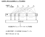
- FIG. 9 is an explanatory diagram showing the configuration of self-organizing map generation processing according to a comparative example
- FIG. 10 is an explanatory diagram showing formulas used in the self-organizing map generation process according to the comparative example
- 7 is a table showing the contents of a self-organizing map according to a comparative example
- FIG. 5 is an explanatory diagram showing an outline of a self-organizing map generated in a comparative example
- FIG. 1 is a block diagram showing the functional configuration of an image forming system 10 according to the first embodiment of the invention.
- the image forming system 10 includes an image forming apparatus 100 as a multifunction peripheral (MFP) and a plurality of personal computers (also simply called PCs) 300 .
- the image forming system 10 is connected to a support server 700 via a hub 500 and a router 600 that constitute a local area network (also simply called a network) LAN, and the Internet.
- the support server 700 has a learning processing unit 710 and is also called a support computer.
- FIG. 2 is an explanatory diagram showing the configuration of the learning system 10 according to the first embodiment.
- the image forming system 10 functions as a learning system that employs edge computing, and is a distributed computing system that collects sensor information at local edges (a plurality of image forming apparatuses 100) and processes and analyzes using the learned data. based on the operating environment.
- the support server 700 is configured by cloud computing.
- the support server 700 can store sensor information collected at the edge (many image forming apparatuses 100) as big data.
- the learning processing unit 710 of the support server 700 can generate a self-organizing map M (SOM) as a state estimation model by executing learning processing, for example, using large-scale parallel software.
- SOM self-organizing map M
- the support server 700 downloads (receives by the many image forming apparatuses 100) the state estimation model as learned data to the edge (the many image forming apparatuses 100).
- the state estimation model is learned data as a self-organizing map M (see FIG. 6).
- the support server 700 further comprises a storage unit 730.
- the storage unit 730 is a storage device composed of a non-temporary recording medium such as a hard disk drive or a flash memory, and stores a control program for processing executed by the first control unit 720 (a second program forming part of the image forming program). ) and data.
- the support server 700 has a first control unit 720 .
- the first control unit 720 includes main storage means such as RAM and ROM, and control means such as MPU (Micro Processing Unit) and CPU (Central Processing Unit) which is an example of the first processor. Also, the first control unit 710 has controller functions related to interfaces such as various I/O, USB (Universal Serial Bus), buses, and other hardware, and controls the entire support server 700 .
- MPU Micro Processing Unit
- CPU Central Processing Unit
- the first control unit 720 includes the learning processing section 710 described above.
- the first control unit 720 functions as the learning processing section 710 as the first processor operates according to the first program.
- the first program and the second program which will be described later, constitute an image forming program.
- the image forming apparatus 100 includes a control unit 110, an image forming section 120, a storage section 140, an image reading section 150, and a communication interface section 160 (also called communication I/F).
- the image reading unit 150 reads an image from a document and generates an image data ID that is digital data.
- Image forming apparatus 100 is connected to a plurality of personal computers 300 via communication interface section 160 and a LAN.
- the communication interface unit 160 is configured to communicate with the support server 700 .
- the personal computer 300 can transmit a print job to the image forming apparatus 100 and cause the image forming apparatus 100 to execute image forming processing.
- a print job can be described, for example, in a page description language (PDL).
- PDL page description language
- the control unit 110 analyzes a print job described in a page description language, extracts objects such as text (characters), images, and vector graphics included in the print job, and executes drawing processing and font processing.
- a print job is also called an imaging job.
- the image forming unit 120 includes a color conversion processing unit 121, a halftone processing unit 122, an exposure unit 124, photosensitive drums (image carriers) 123c to 123k which are amorphous silicon photosensitive members, and developing units 125c to 125k. , charging units 126 c to 126 k and a state sensor 127 .
- the color conversion processing unit 121 color-converts the image data ID, which is RGB image data, and the RGB image data in the print job into CMYK data.
- the halftone processing unit 122 performs halftone processing on the CMYK data to generate print data PD as CMYK halftone data.
- the halftone data represents the formation state of dots formed by each toner of CMYK, and is also called dot data.
- the state sensor 127 functions as a state measuring unit and, as the above sensor information, the internal state of the image forming apparatus 100, that is, the temperature and humidity inside the image forming apparatus 100, and the photosensitive drums 123c to 123c of the image forming unit 120.
- Total number of revolutions of 123k (an example of total running distance) x1, exposure amount of exposure unit 124 x2, patch density (an example of image forming density) x3 by image forming unit 120, number of prints (an example of image forming amount) x4, etc. can be measured.
- the state sensor 127 detects that each photosensitive drum 123 has an N-dimensional (in this example, four-dimensional) feature vector X (x1, x2, x3, x4) as a state quantity of the data space, which is the space of the input data. ) can be obtained. That is, the state sensor 127 includes a thermometer, a hygrometer, an optical sensor that measures the total number of rotations of the photosensitive drums 123c to 123k, the exposure amount of the exposure unit 124, the patch density of the image forming unit 120, and the number of prints. is configured by a control unit 110 that measures
- the storage unit 140 is a storage device composed of a non-temporary recording medium such as a hard disk drive or a flash memory, and stores a control program for processing executed by the control unit 110 (including a first program forming part of an image forming program). ) and data.
- the storage unit 140 further has a sensor information storage area R1 and a learned model storage area R2 in this embodiment.
- the control unit (second control unit) 110 includes main storage means such as RAM and ROM, and control means such as MPU (Micro Processing Unit) and CPU (Central Processing Unit) which is an example of the second processor. . Also, the control unit 110 has a controller function related to interfaces such as various I/O, USB (Universal Serial Bus), buses, and other hardware, and controls the entire image forming apparatus 100 .
- main storage means such as RAM and ROM
- control means such as MPU (Micro Processing Unit) and CPU (Central Processing Unit) which is an example of the second processor.
- the control unit 110 has a controller function related to interfaces such as various I/O, USB (Universal Serial Bus), buses, and other hardware, and controls the entire image forming apparatus 100 .
- the control unit 110 includes a learning data processing section 111 and a state estimation section 112 .
- the control unit 110 functions as a learning data processing section 111 and a state estimation section 112 as the second processor operates according to the second program.
- the learning data processing unit 111 uploads the feature vector X (x1, x2, x3, x4) acquired from the state sensor 127 to the support server 700 .
- the state estimation unit 112 can estimate the internal state of the image forming apparatus 100 through clustering processing using the self-organizing map M downloaded from the support server 700 .
- the self-organizing map generation function can be implemented in the support server 700 using tools and libraries such as Python and Tensorflow.
- FIG. 3 is a flowchart showing the contents of the self-organizing map generation process according to the comparative example.
- FIG. 4 is an explanatory diagram showing the configuration of the self-organizing map generation process according to the comparative example.
- FIG. 5 is a table showing contents of a self-organizing map according to a comparative example.
- Self-Organizing Map (SOM) is an unsupervised neural network algorithm proposed by T. Kohonen, and is a data analysis method that nonlinearly maps high-dimensional data onto a two-dimensional plane. . Since this algorithm is an unsupervised neural network algorithm, it has the advantage that it can be easily implemented without preparing a teacher.
- step S110c the image forming system 10 executes input data accumulation processing.
- learning data processing section 111 of control unit 110 of image forming apparatus 100 uses state sensor 127 at a first predetermined interval (for example, one week) to obtain feature vector X(x1 , x2, x3, and x4) are acquired and stored in the sensor information storage area R1 of the storage unit 140.
- FIG. 1 A first predetermined interval (for example, one week) to obtain feature vector X(x1 , x2, x3, and x4) are acquired and stored in the sensor information storage area R1 of the storage unit 140.
- the learning data processing unit 111 reads out a plurality of state quantities including the feature vector X from the sensor information storage area R1 at a second interval (for example, one month) as a predetermined interval longer than the first interval, and supports Upload to server 700 .
- the learning processing unit 710 receives a preset amount, that is, a sufficient amount for learning for generating a self-organizing map, from a plurality of image forming apparatuses 100 with a plurality of state quantities including the feature vector X as learning data. When it is determined that they have gathered, the process proceeds to step S120c.
- step S120c the learning processing unit 710 of the support server 700 executes input/output layer setting processing.
- the learning processing unit 710 sets the feature vector X from a plurality of state quantities in the input layer of the self-organizing map, and has 16 nodes that specify each point in the map space, which is the space to be mapped. Shall set the output layer.
- the learning processing unit 710 sets a 4 ⁇ 4 two-dimensional map as the map space.
- a self-organizing map is a two-layer neural network composed of an input layer and an output layer, as shown in FIG.
- Each node in the output layer has an N-dimensional weight vector Y(y1, y2 , y3, y4).
- step S130c the learning processing unit 710 executes initial setting processing.
- learning processing unit 710 sets weight vector Y (y1, y2, y3, y4) using, for example, random numbers.
- random numbers are used to set the initial value of the weight Y for each link.
- the weight vector Y is a vector to be updated by learning processing.
- step S140 the learning processing unit 710 executes winner node determination processing.
- the learning processing unit 710 determines a winner node using feature vectors (x1, x2, x3, x4) as learning data collected from the plurality of image forming apparatuses 100 as input data.
- the winning node is selected as the node with the weight vector Y whose Euclidean distance is closest to the feature vector X(x1, x2, x3, x4) of the input data.
- step S150c the learning processing unit 710 executes weight vector update processing.
- the learning processing unit 710 uses a predetermined update formula set in advance to update the weight vector Y of the winner node and the weight vectors Y of neighboring nodes that are neighboring nodes of the winner node.
- the learning data is used to repeat and update a predetermined number of times.
- the update is performed so that the weight vector Y of the winner node and the weight vector Y of the neighboring nodes are brought closer to the feature vector X (x1, x2, x3, x4) of the input data.
- the update amount is set so that the weight vector Y of the winner node has the largest update amount, and the closer the node is to the winner node, the closer the update amount of the weight vector Y of the neighboring node is to the update amount of the weight vector Y of the winner node. .
- the winner node and neighboring nodes are also called update target nodes.
- FIG. 5 is an explanatory diagram showing formulas used in the self-organizing map generation process according to the comparative example.
- Equation 1c is the objective function Fc used in the self-organizing mapping algorithm.
- the self-organizing mapping is processed to maximize the objective function Fc with negative values. That is, the self-organizing mapping is processed so that the Euclidean distance between the feature vector X of the input data and the update target node is reduced.
- Equation 2c is a partial differential equation derived by partially differentiating Equation 1c with weight vector Y.
- Formula 3c is an update formula derived as a solution of the partial differential equation (Formula 2c).
- the update formula 3c is a formula for updating the weight vector Y of the update target node so as to approach the feature vector X of the input data.
- Such winner node determination processing (step S140) and weight vector update processing (step S150) are executed in batch processing, so the total amount of processing is reduced compared to online learning, and stable state estimation is realized. can do.
- the learning processing unit 710 outputs the state estimation model.
- the state estimation model is constructed as a weight vector Y of all nodes (16 nodes in this example) of the output layer.
- Support server 700 notifies a plurality of image forming apparatuses 100 that learned state estimation models are available, and downloads the state estimation models in response to requests from image forming apparatuses 100 .
- a plurality of image forming apparatuses 100 store state estimation models in the learned model storage area R2 of the storage unit 140 .
- FIG. 6 is a table showing the contents of the self-organizing map according to the comparative example.
- the state estimation model M self-organizing map
- the state estimation model M is configured as a table showing a plurality of state quantities (input data) of the photoreceptor drum 123 and the estimated state of the photoreceptor drum 123 for each node of the output layer. It is In the state estimation model M, descriptions such as “small”, “normal”, and “low” of the input data are expressions for making the explanation easier to understand, and in reality, normalized values of 0 to 1 are entered. .
- the state estimation unit 112 of the control unit 110 of the plurality of image forming apparatuses 100 uses the state estimation model M stored in the learned model storage area R2, and obtains a plurality of state quantities using the state sensor 127.
- the state of the photosensitive drum 123 can be estimated (diagnosed) based on the latest feature vector X (x1, x2, x3, x4), that is, the total running distance x1, the exposure amount x2, the print density x3, and the number of prints x4. can.
- the state estimating unit 112 corresponds to node 9, and the photoreceptor drum 123 It can be specified that the state is "normal".
- FIG. 7 is an explanatory diagram showing an outline of a self-organizing map generated in a comparative example.
- FIG. 7(a) shows a state of a self-organizing map as a learning result according to the comparative example.
- FIG. 7(a) conceptually shows the state estimation model M as an image in a two-dimensional map.
- the clustering by the learning processing unit 710 classifies the nodes 1 to 8 of the state estimation model M into the state A cluster, the nodes 9 to 12 into the state B cluster, and the nodes 13 and 14 into the state C cluster.
- the node 15 is classified into the state D cluster
- the node 16 is classified into the state E cluster.
- FIG. 7(b) shows a self-organizing map as a result of additional learning according to the comparative example.
- the additional learning according to the comparative example is learning processing according to the flowchart of the batch type learning processing (FIG. 3) according to the comparative example, using the state estimation model M as the previous learning result and using it as the initial value of the weight vector Y.
- FIG. 7B shows that the phases of the clusters have changed significantly from the previous learning results, and the mutual positional relationships of the clusters have changed. The reason for this is that the previous learning result does not contribute to the weight update formula 3c at the time of additional learning.
- the inventors of the present application created the following novel configuration.
- FIG. 8 is an explanatory diagram showing an overview of the additional learning process according to the first embodiment.
- FIG. 9 is a flowchart showing additional learning processing according to the first embodiment.
- FIG. 10 is an explanatory diagram showing the configuration of additional learning processing according to the first embodiment.
- the number of wins for each node that is, the number of node hits
- an additional learning process is created in which weighting is performed based on the number of node hits. .
- step S110 learning processing unit 710 acquires feature A plurality of state quantities including a vector X (x1, x2, x3, x4) are acquired from the plurality of image forming apparatuses 100 .
- the state estimation model M generated in the previous learning process is also called a first self-organizing map.
- step S120 the learning processing unit 710 executes input/output layer setting processing.
- the same configuration as the previous learning shall be adopted.
- step S130 the learning processing unit 710 executes initial setting processing.
- the learning processing unit 710 sets the state estimation model M as an initial state in principle.
- the learning processing unit 710 can also change the contents of the initial settings according to changes such as deletion, addition, and replacement of variables.
- step S140 the learning processing unit 710 executes winner node determination processing.
- the contents of the winner node determination process are the same as those of the comparative example.
- step S141 the learning processing unit 710 executes node hit count processing unlike the comparative example. In the node hit count process, the learning processing unit 710 counts the number of times each node becomes a winner for each node during batch processing.
- step S150 the learning processing unit 710 executes weight vector update processing.
- the vector update process (step S150) according to the first embodiment differs from the weight vector update process (step S150c) is different.
- FIG. 11 is an explanatory diagram showing formulas used in the additional learning process according to the first embodiment.
- Equation 1 is the objective function F of the self-organizing mapping algorithm in additional learning.
- the first term T1 of the objective function F represents the objective function for the additional learning, that is, the contribution of the additional learning to the objective function F.
- the second term T2 of the objective function F represents the objective function for the previous learning, that is, the contribution of the previous learning to the objective function F.
- the first term T1 of the objective function F is the number of node hits S of the additional learning data (second learning data), the additional learning data and the self-organizing map to be updated for each node of the self-organizing map to be updated. contains the product of the Euclidean distance between
- the second term T2 of the objective function F is the number of node hits R of the previous learning data (first learning data) and the previously learned self-organizing map for each node of the self-organizing map to be updated. It contains the product of the Euclidean distance with the self-organizing map to be updated.
- the node hit number R of the previous learning data is also called the first hit number.
- the node hit count S of the additional learning data is also called a second hit count. Therefore, the update amount of the weight vector Y of the update target node is adjusted by the first hit count, the second hit count, and the previous learning data.
- Equation 2 is a partial differential equation derived by partially differentiating Equation 1 with weight vector Y.
- Formula 3 is an update formula derived as a solution of the partial differential equation (Formula 2). The update formula 3 considers the contribution rate based on the learning amount of the additional learning data and the learning amount of the previous learning data for each node, and updates the weight vector Y of the update target node so as to approach the feature vector X of the input data. is.
- Formula 3 can also be interpreted as follows. That is, according to Equation 3, it is possible to adjust the contribution rate of the additional learning data X and the learned weight vector w to the weight vector Y from the node hit numbers S and R. Specifically, when the number of node hits R of the previous learning data is 0, that is, under the conditions of the initial learning when the previous learning is not performed, the number of node hits S during learning is canceled, and Equation 3 is a comparative example. is the same as the update formula of formula 3c.
- Equation 3 when the number of node hits during additional learning increases sharply, the contribution rate of the weight vector w during previous learning decreases, which means that the self-organizing model is rebuilt.
- the ratio of the number of additional learning node hits S during additional learning and the number R of node hits during previous learning is A:A.
- the additional learning data X does not include the previously learned data set, additional learning is possible with a data set containing only the additional learning data. Therefore, it is possible to suppress the enlargement of the learning data set and the additional learning processing time.
- FIG. 12 is an explanatory diagram showing an overview of the self-organizing map generated in the first embodiment.
- the clustering by the learning processing unit 710 is such that each cluster of the state estimation model M learns while maintaining the phase with each other, and each region thereof is expanded. This makes it possible to easily analyze changes in the self-organizing map due to additional learning.
- the state estimation model Ma generated by the additional learning process is also called a second self-organizing map.
- the image forming apparatus 100 considers the number of winners in each node, that is, the number of node hits, as one of the indices representing the amount of learning, and performs weighting based on the number of node hits. Since the additional learning process is executed, each cluster of the state estimation model M can learn while maintaining the phase with each other. This makes it possible to easily analyze changes in the self-organizing map due to additional learning.
- the image forming apparatus 100 according to the first embodiment is capable of additional learning using a data set of only additional learning data, compared to the method of re-learning from the beginning, the learning data set is enlarged and the additional learning process is excessive. It is possible to suppress the occurrence of time.
- the image forming apparatus 100 according to the first embodiment can update the weights while maintaining the topological relationship of the nodes. parameter transition, etc.) can also be performed efficiently. Furthermore, there is no need to relabel the nodes after additional learning to maintain the topological relationships of the nodes.
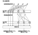
- FIG. 13 is an explanatory diagram showing the configuration of the self-organizing map generation process according to the second embodiment.
- the self-organizing map generation processing according to the second embodiment is different from general self-organizing map generation processing in that the low-resolution clustering for generating the low-resolution state estimation model L and the high-resolution state estimation model H are performed.
- Multiple (two in this example) state estimation models can be generated with multiple stages of clustering, including high-resolution clustering to generate them.
- the learning processing unit 710 executes the same processing as the self-organizing map generation processing according to the first embodiment. Thereby, the learning processing unit 710 can generate the low-resolution state estimation model L using the objective function Fc.
- the low-resolution state estimation model L (y1 to y16) is the same learning model as the state estimation model M (see FIG. 6) generated in the self-organizing map generation process according to the comparative example.
- the state estimation model M as can be seen from FIG. 6, nodes 1 to 12 are classified as state A (good) or state B (normal), and nodes 13 to 16 are classified as abnormal (states C to E). .
- the learning processing unit 710 calculates feature vectors X(xi, xi+1, . • Extract only xj).
- the learning processing unit 710 uses the extracted input data and performs clustering again using a two-dimensional map of 4 ⁇ 4 (16 nodes in total) as a map space.
- the learning processing unit 710 uses the objective function Fc to reclassify the abnormal states of the nodes 13 to 16, which have been classified into four, with high resolution, and the high resolution state estimation model H (y'1 to y' 16) can be generated.
- FIG. 14 is a flowchart showing the contents of self-organizing map generation processing according to the second embodiment.
- FIG. 15(a) is an explanatory diagram showing a high-resolution learning process according to the second embodiment.
- the self-organizing map generation process according to the second embodiment is the first embodiment in that a plurality of (two in this example) state estimation models are generated by multi-stage clustering including low-resolution clustering and high-resolution clustering. It is different from the self-organizing map generation processing according to the form.
- the first processing of steps S110 to S130 and steps S140 to S160 is performed in the same manner as the self-organizing map generation processing according to the first embodiment.
- a state estimation model L (y1 to y16: see FIG. 15(a)) of normal resolution) is generated.
- the learning processing unit 710 executes learning data extraction processing (step S170) in advance.
- the learning processing unit 710 extracts learning data corresponding to a node that meets a preset criterion (classified as abnormal in this example) and learning data corresponding to nodes in the vicinity of the node. to extract
- the learning processing unit 710 processes the learning data of the nodes classified as abnormal (nodes 13 to 16) in the low-resolution state estimation model L (same as the state estimation model M), and the nodes 4 and 7 in the vicinity thereof. , 8, 10, and 12 training data are extracted. Using the extracted learning data extracted in this way, the learning processing unit 710 uses a 4 ⁇ 4 (total of 16 nodes) two-dimensional map, and uses the low-resolution state estimation model L as an initial value in the first embodiment.
- a high-resolution state estimation model H (y'1 to y'16: see FIG. 15) is generated by the same method as the self-organizing map generation process, and the process is terminated (step S180).
- the learning processing unit 710 notifies all of the plurality of image forming apparatuses 100 of the generation of the low-resolution state estimation model L and the high-resolution state estimation model H.
- the learning processing unit 710 downloads the low-resolution state estimation model L and the high-resolution state estimation model H in response to requests from a plurality of image forming apparatuses 100 .
- the high-resolution state estimation model H is configured such that some nodes in the low-resolution state estimation model L taxonomy are partially increased in resolution.
- the learning processing unit 710 is configured so as to generate an ultra-high resolution state estimation model UH configured so that the resolution is partially increased in some nodes of the classification of the high resolution state estimation model H. may
- FIG. 15(b) is an explanatory diagram showing state estimation processing according to the second embodiment.
- step S210 the state estimation section 112 of the control unit 110 of each of the plurality of image forming apparatuses 100 executes low-resolution state estimation processing.
- the state estimation unit 112 uses the low-resolution state estimation model L downloaded and stored in the learned model storage area R2, and the latest feature vector obtained using the state sensor 127.
- the state of the photosensitive drum 123 is estimated based on X(x1, x2, x3, x4) (primary diagnosis).
- step S220 the state estimator 112 determines whether the primary diagnosis result corresponds to normal (that is, good or normal). If it is determined to be normal, that is, if it is determined to correspond to nodes 1 to 12 in the state estimation model M (see FIG. 6), the state estimation unit 112 advances the process to step S230 and determines that the node is normal. A display or the like (not shown) notifies the user of the fact that there is.
- the state estimation unit 112 proceeds to step processing. Proceed to S240.
- step S240 the state estimation unit 112 executes high-resolution state estimation processing.
- the state estimation unit 112 uses the high-resolution state estimation model H downloaded and stored in the learned model storage area R2, and uses the latest feature vector obtained using the state sensor 127.
- the state of the photosensitive drum 123 is estimated based on X(x1, x2, x3, x4) (secondary diagnosis).
- the state estimating unit 112 can determine an abnormal mode, ie, a more detailed abnormal state (abnormal mode) (step S250), and report the details to the user on a display or the like (not shown).
- the high-resolution state estimation model H is also called the first high-resolution self-organizing map.
- FIG. 16 is an explanatory diagram showing the configuration of self-organizing map generation processing according to the second embodiment.
- the learning processing unit 710 uses the objective function F, the number of node hits S of the additional learning data and the number of node hits R of the previous learning data, and the low-resolution state estimation model L and the high-resolution state estimation model H.
- additional learning can be performed in the same manner as in the first embodiment.
- the model generated by performing additional training on the high-resolution state estimation model H is also called a second high-resolution self-organizing map.
- the objective function Fc of the comparative example may be used.
- the learning processing unit 710 effectively utilizes the second learning data acquired later in chronological order, and has the advantage of being able to promote the classification of abnormal states that have increased due to an increase in the number of years of operation. be.
- the objective function F may also be used when the low-resolution state estimation model L is used to generate the high-resolution state estimation model H. This has the advantage that the learning processing unit 710 can easily analyze the change from clustering by the low-resolution state estimation model L to the high-resolution state estimation model H. FIG. Furthermore, by correcting the number of node hits, it is also possible to adjust the classification method to an appropriate position between the two.
- the image forming apparatus 100 according to the second embodiment uses a learning model with the same number of nodes to learn multiple times by changing the extracted input data narrowed down by a specific classification, thereby obtaining a common inference execution model. It is possible to implement multiple types of models with different resolutions. As a result, the image forming apparatus 100 according to the second embodiment can implement resource-saving implementation and extensive and highly accurate state estimation.
- the present invention can be implemented not only in the above embodiments, but also in the following modifications.
- the learning data processing unit 111 uploads the learning data acquired from the state sensor 127 to the support server 700 at specific intervals (second intervals in the first embodiment).
- the learning data may be uploaded separately before and after part replacement according to part replacement such as replacement of a photosensitive drum.
- the image forming system 10 estimates the state of the photosensitive drum, but is not limited to the photosensitive drum. At least one state estimate may be made, including an overall state estimate.
Landscapes
- Engineering & Computer Science (AREA)
- Theoretical Computer Science (AREA)
- Physics & Mathematics (AREA)
- Software Systems (AREA)
- General Physics & Mathematics (AREA)
- Computing Systems (AREA)
- Artificial Intelligence (AREA)
- Mathematical Physics (AREA)
- Data Mining & Analysis (AREA)
- Evolutionary Computation (AREA)
- General Engineering & Computer Science (AREA)
- Biomedical Technology (AREA)
- Molecular Biology (AREA)
- General Health & Medical Sciences (AREA)
- Computational Linguistics (AREA)
- Biophysics (AREA)
- Life Sciences & Earth Sciences (AREA)
- Health & Medical Sciences (AREA)
- Computer Vision & Pattern Recognition (AREA)
- Medical Informatics (AREA)
- Control Or Security For Electrophotography (AREA)
- Image Analysis (AREA)
Priority Applications (2)
| Application Number | Priority Date | Filing Date | Title |
|---|---|---|---|
| JP2023520896A JP7529150B2 (ja) | 2021-05-14 | 2022-03-24 | 画像形成部の状態を推定する画像形成システム、画像形成方法、及び画像形成プログラム |
| US18/289,770 US20240273403A1 (en) | 2021-05-14 | 2022-03-24 | Image formation system, image formation method, and image formation program for estimating state of image forming device |
Applications Claiming Priority (2)
| Application Number | Priority Date | Filing Date | Title |
|---|---|---|---|
| JP2021082550 | 2021-05-14 | ||
| JP2021-082550 | 2021-05-14 |
Publications (1)
| Publication Number | Publication Date |
|---|---|
| WO2022239516A1 true WO2022239516A1 (ja) | 2022-11-17 |
Family
ID=84029535
Family Applications (1)
| Application Number | Title | Priority Date | Filing Date |
|---|---|---|---|
| PCT/JP2022/014104 Ceased WO2022239516A1 (ja) | 2021-05-14 | 2022-03-24 | 画像形成部の状態を推定する画像形成システム、画像形成方法、及び画像形成プログラム |
Country Status (3)
| Country | Link |
|---|---|
| US (1) | US20240273403A1 (https=) |
| JP (1) | JP7529150B2 (https=) |
| WO (1) | WO2022239516A1 (https=) |
Citations (1)
| Publication number | Priority date | Publication date | Assignee | Title |
|---|---|---|---|---|
| JP2011086132A (ja) * | 2009-10-16 | 2011-04-28 | Tokyo Institute Of Technology | 連想記憶装置、連想記憶方法、及びプログラム |
Family Cites Families (1)
| Publication number | Priority date | Publication date | Assignee | Title |
|---|---|---|---|---|
| JP4767595B2 (ja) * | 2005-06-15 | 2011-09-07 | パナソニック株式会社 | 対象物検出装置及びその学習装置 |
-
2022
- 2022-03-24 WO PCT/JP2022/014104 patent/WO2022239516A1/ja not_active Ceased
- 2022-03-24 US US18/289,770 patent/US20240273403A1/en active Pending
- 2022-03-24 JP JP2023520896A patent/JP7529150B2/ja active Active
Patent Citations (1)
| Publication number | Priority date | Publication date | Assignee | Title |
|---|---|---|---|---|
| JP2011086132A (ja) * | 2009-10-16 | 2011-04-28 | Tokyo Institute Of Technology | 連想記憶装置、連想記憶方法、及びプログラム |
Non-Patent Citations (1)
| Title |
|---|
| ATSUSHI SHIMADA, RIN-ICHIRO TANIGUCHI : "Incremental Learning in Self-Organizing Map", RESEARCH REPORTS ON INFORMATION SCIENCE AND ELECTRICALENGINEERING, KYUSHU UNIVERSITY, FUKUOKA,, JP, vol. 12, no. 1, 13 December 2006 (2006-12-13), JP , pages 49 - 54, XP093004480, ISSN: 1342-3819, DOI: 10.15017/1517818 * |
Also Published As
| Publication number | Publication date |
|---|---|
| JP7529150B2 (ja) | 2024-08-06 |
| US20240273403A1 (en) | 2024-08-15 |
| JPWO2022239516A1 (https=) | 2022-11-17 |
Similar Documents
| Publication | Publication Date | Title |
|---|---|---|
| US7903844B2 (en) | Failure analysis system, failure analysis method, and program product for failure analysis | |
| JP5413012B2 (ja) | 画像欠陥診断システム、画像形成装置、およびプログラム | |
| JP7242495B2 (ja) | 推論結果評価システム、推論結果評価装置及びその方法 | |
| JP6992780B2 (ja) | 情報処理装置、学習装置及び学習済モデル | |
| CN111340178A (zh) | 学习装置、印刷控制装置以及存储装置 | |
| US11481266B2 (en) | Diagnosing an information processing system malfunction via diagnostic modeling | |
| US20230115987A1 (en) | Data adjustment system, data adjustment device, data adjustment method, terminal device, and information processing apparatus | |
| JP2022029702A (ja) | 学習システム、電子機器、及びその制御方法、並びにプログラム | |
| JP2020009156A (ja) | システム、システムの制御方法及びプログラム | |
| US10949135B2 (en) | Print system, print setting prediction method, and non-transitory computer-readable storage medium | |
| US8724168B2 (en) | Updating a smoothness constrained cluster model for color control in a color management system | |
| CN118781028A (zh) | 掩模版校正方法、装置、计算机设备及可读存储介质 | |
| US8531734B2 (en) | Cluster model for controlling color in a color marking device | |
| US20210149605A1 (en) | Print system, server, and print method | |
| JP7529150B2 (ja) | 画像形成部の状態を推定する画像形成システム、画像形成方法、及び画像形成プログラム | |
| JP5676465B2 (ja) | 複写システム | |
| JP4844606B2 (ja) | 画像分類装置及びプログラム | |
| JP5471659B2 (ja) | 情報処理装置、画像処理システム、及びプログラム | |
| US12113938B2 (en) | Image processing system, image processing apparatus, control method | |
| JP7059978B2 (ja) | 情報処理装置、学習装置及び学習済モデル | |
| JP7512765B2 (ja) | 印刷時推定画像生成装置、印刷時推定画像生成方法及びプログラム | |
| JP2013061732A (ja) | 画像識別情報付与プログラム及び画像識別情報付与装置 | |
| JP7408325B2 (ja) | 情報処理装置、学習方法およびプログラム | |
| US20260099286A1 (en) | Information processing system, non-transitory computer readable medium storing information processing program, and information processing method | |
| US20250208555A1 (en) | Electronic apparatus, anomaly detection system, and anomaly detection method |
Legal Events
| Date | Code | Title | Description |
|---|---|---|---|
| 121 | Ep: the epo has been informed by wipo that ep was designated in this application |
Ref document number: 22807221 Country of ref document: EP Kind code of ref document: A1 |
|
| WWE | Wipo information: entry into national phase |
Ref document number: 2023520896 Country of ref document: JP |
|
| WWE | Wipo information: entry into national phase |
Ref document number: 18289770 Country of ref document: US |
|
| NENP | Non-entry into the national phase |
Ref country code: DE |
|
| 122 | Ep: pct application non-entry in european phase |
Ref document number: 22807221 Country of ref document: EP Kind code of ref document: A1 |