WO2022239397A1 - 室内機 - Google Patents
室内機 Download PDFInfo
- Publication number
- WO2022239397A1 WO2022239397A1 PCT/JP2022/008971 JP2022008971W WO2022239397A1 WO 2022239397 A1 WO2022239397 A1 WO 2022239397A1 JP 2022008971 W JP2022008971 W JP 2022008971W WO 2022239397 A1 WO2022239397 A1 WO 2022239397A1
- Authority
- WO
- WIPO (PCT)
- Prior art keywords
- flap
- indoor
- air
- control
- control unit
- Prior art date
- Legal status (The legal status is an assumption and is not a legal conclusion. Google has not performed a legal analysis and makes no representation as to the accuracy of the status listed.)
- Ceased
Links
Images






Classifications
-
- F—MECHANICAL ENGINEERING; LIGHTING; HEATING; WEAPONS; BLASTING
- F24—HEATING; RANGES; VENTILATING
- F24F—AIR-CONDITIONING; AIR-HUMIDIFICATION; VENTILATION; USE OF AIR CURRENTS FOR SCREENING
- F24F1/00—Room units for air-conditioning, e.g. separate or self-contained units or units receiving primary air from a central station
- F24F1/0007—Indoor units, e.g. fan coil units
- F24F1/0018—Indoor units, e.g. fan coil units characterised by fans
- F24F1/0025—Cross-flow or tangential fans
-
- F—MECHANICAL ENGINEERING; LIGHTING; HEATING; WEAPONS; BLASTING
- F24—HEATING; RANGES; VENTILATING
- F24F—AIR-CONDITIONING; AIR-HUMIDIFICATION; VENTILATION; USE OF AIR CURRENTS FOR SCREENING
- F24F1/00—Room units for air-conditioning, e.g. separate or self-contained units or units receiving primary air from a central station
- F24F1/0007—Indoor units, e.g. fan coil units
- F24F1/0043—Indoor units, e.g. fan coil units characterised by mounting arrangements
- F24F1/0057—Indoor units, e.g. fan coil units characterised by mounting arrangements mounted in or on a wall
-
- F—MECHANICAL ENGINEERING; LIGHTING; HEATING; WEAPONS; BLASTING
- F24—HEATING; RANGES; VENTILATING
- F24F—AIR-CONDITIONING; AIR-HUMIDIFICATION; VENTILATION; USE OF AIR CURRENTS FOR SCREENING
- F24F11/00—Control or safety arrangements
- F24F11/70—Control systems characterised by their outputs; Constructional details thereof
- F24F11/72—Control systems characterised by their outputs; Constructional details thereof for controlling the supply of treated air, e.g. its pressure
- F24F11/74—Control systems characterised by their outputs; Constructional details thereof for controlling the supply of treated air, e.g. its pressure for controlling air flow rate or air velocity
-
- F—MECHANICAL ENGINEERING; LIGHTING; HEATING; WEAPONS; BLASTING
- F24—HEATING; RANGES; VENTILATING
- F24F—AIR-CONDITIONING; AIR-HUMIDIFICATION; VENTILATION; USE OF AIR CURRENTS FOR SCREENING
- F24F11/00—Control or safety arrangements
- F24F11/70—Control systems characterised by their outputs; Constructional details thereof
- F24F11/72—Control systems characterised by their outputs; Constructional details thereof for controlling the supply of treated air, e.g. its pressure
- F24F11/74—Control systems characterised by their outputs; Constructional details thereof for controlling the supply of treated air, e.g. its pressure for controlling air flow rate or air velocity
- F24F11/75—Control systems characterised by their outputs; Constructional details thereof for controlling the supply of treated air, e.g. its pressure for controlling air flow rate or air velocity for maintaining constant air flow rate or air velocity
-
- F—MECHANICAL ENGINEERING; LIGHTING; HEATING; WEAPONS; BLASTING
- F24—HEATING; RANGES; VENTILATING
- F24F—AIR-CONDITIONING; AIR-HUMIDIFICATION; VENTILATION; USE OF AIR CURRENTS FOR SCREENING
- F24F11/00—Control or safety arrangements
- F24F11/70—Control systems characterised by their outputs; Constructional details thereof
- F24F11/72—Control systems characterised by their outputs; Constructional details thereof for controlling the supply of treated air, e.g. its pressure
- F24F11/79—Control systems characterised by their outputs; Constructional details thereof for controlling the supply of treated air, e.g. its pressure for controlling the direction of the supplied air
-
- Y—GENERAL TAGGING OF NEW TECHNOLOGICAL DEVELOPMENTS; GENERAL TAGGING OF CROSS-SECTIONAL TECHNOLOGIES SPANNING OVER SEVERAL SECTIONS OF THE IPC; TECHNICAL SUBJECTS COVERED BY FORMER USPC CROSS-REFERENCE ART COLLECTIONS [XRACs] AND DIGESTS
- Y02—TECHNOLOGIES OR APPLICATIONS FOR MITIGATION OR ADAPTATION AGAINST CLIMATE CHANGE
- Y02B—CLIMATE CHANGE MITIGATION TECHNOLOGIES RELATED TO BUILDINGS, e.g. HOUSING, HOUSE APPLIANCES OR RELATED END-USER APPLICATIONS
- Y02B30/00—Energy efficient heating, ventilation or air conditioning [HVAC]
- Y02B30/70—Efficient control or regulation technologies, e.g. for control of refrigerant flow, motor or heating
Definitions
- Patent Document 1 Japanese Unexamined Patent Application Publication No. 2002-195595 discloses an air conditioner that includes a cylindrical cross-flow fan and a casing that accommodates the cross-flow fan and has an outlet for blowing out airflow generated by the cross-flow fan. An indoor unit of the device is disclosed.
- This disclosure proposes an indoor unit that can ensure the reach of the airflow blown out from the outlet even during low-load operation.
- the indoor unit of the first point of view is the indoor unit of an air conditioner.
- An indoor unit includes a cross-flow fan, a casing, a flap, and a controller.
- a cross-flow fan is a cylindrical fan.
- the casing accommodates the cross-flow fan, and is formed with an air outlet for blowing out the airflow generated by the cross-flow fan.
- the flap opens and closes the outlet.
- the controller controls the attitude of the flap.
- the control unit throttles the ventilation path formed by the flap and the outlet when the amount of airflow generated by the cross-flow fan or the number of rotations of the cross-flow fan during low-load air-conditioning operation with a low air-conditioning operation load falls below a predetermined value.
- the first control is executed to control the attitude of the flap as follows.
- the indoor unit according to the second aspect is the indoor unit according to the first aspect, wherein in the first control, the control unit controls the attitude of the flap so that the amount of constriction of the ventilation passage increases as the air volume or rotation speed decreases. .
- the indoor unit according to the third aspect is the indoor unit according to the second aspect, in which the control unit controls the attitude of the flap so that the amount of constriction of the ventilation passage increases stepwise in the first control.
- the indoor unit according to the fourth aspect is the indoor unit according to any one of the first aspect to the third aspect, and the cross-flow fan has an outer diameter of 115 mm or more.
- the indoor unit of the fifth aspect is the indoor unit of any one of the first to fourth aspects, and is a wall-mounted type.
- the cross-flow fan is housed in the casing with its longitudinal direction aligned with the horizontal direction.
- the outlet is formed below the cross-flow fan in the vertical direction.
- the control unit controls the attitude of the flap so that the airflow blown out from the air outlet is directed downward from the air outlet in the vertical direction.
- the indoor unit of the seventh aspect is the indoor unit of any one of the first aspect to the sixth aspect, and the cross-flow fan has an outer diameter of 115 mm or more and 150 mm or less.
- the wind speed of the airflow blown out from the outlet when the first control is executed is 2.8 m or more and 5 m or less per second.
- FIG. 1 is a schematic configuration diagram of an air conditioner 1;
- FIG. 2 is a diagram showing a refrigerant circuit 10 of the air conditioner 1;
- FIG. 3 is a cross-sectional view of the indoor unit 3.
- FIG. 3 is a control block diagram of an indoor controller 62.
- FIG. 3 is a control block diagram of an outdoor controller 61.
- FIG. 4 is a flowchart showing a control flow of first control;
- FIG. 4 is a cross-sectional view of the indoor unit 3 for explaining the attitude of the flap 35 during the first control;
- FIG. 11 is a cross-sectional view of the indoor unit 3 showing how the indoor control unit 62 according to Modification A changes the attitude of the flap 35 in the first control during cooling operation.
- FIG. 4 is a flowchart showing a control flow of first control;
- FIG. 4 is a cross-sectional view of the indoor unit 3 for explaining the attitude of the flap 35 during the first control;
- FIG. 11 is a cross-sectional view
- FIG. 11 is a cross-sectional view of the indoor unit 3 showing how the indoor control unit 62 according to Modification B changes the attitude of the flap 35 in the first control during the heating operation.
- 10 is a flowchart showing a control flow of first control executed by an indoor control unit 62 in the air conditioner 1 according to Modification C.
- FIG. 10 is a flowchart showing a control flow of first control executed by an indoor control unit 62 in the air conditioner 1 according to Modification C.
- the air conditioner 1 is a device that uses a vapor compression refrigeration cycle to realize an air conditioning operation including a cooling operation and a heating operation in the target space SP.
- FIG. 1 is a schematic configuration diagram of the air conditioner 1.
- the air conditioner 1 mainly includes an outdoor unit 2, an indoor unit 3, a liquid refrigerant communication pipe 41, and a gas refrigerant communication pipe 42, as shown in FIG.
- the air conditioner 1 has only one indoor unit 3, but the air conditioner 1 may have a plurality of indoor units 3 connected in parallel.
- Both the liquid refrigerant communication pipe 41 and the gas refrigerant communication pipe 42 are pipes that connect the outdoor unit 2 and the indoor unit 3 .
- FIG. 2 is a diagram showing the refrigerant circuit 10 of the air conditioner 1. As shown in FIG.
- the refrigerant circuit 10 is configured by connecting the outdoor unit 2 and the indoor unit 3 via a liquid refrigerant communication pipe 41 and a gas refrigerant communication pipe 42 .
- the refrigerant circuit 10 mainly includes a compressor 21 of the outdoor unit 2, a flow direction switching mechanism 22, an outdoor heat exchanger 23, an expansion valve 24, and an indoor heat exchanger 31 of the indoor unit 3.
- the indoor unit 3 is installed in the target space SP.
- the indoor unit 3 is a wall-mounted unit installed on the wall of the target space SP.
- FIG. 3 is a cross-sectional view of the indoor unit 3.
- the indoor unit 3 mainly includes an indoor heat exchanger 31, an indoor fan 32, a liquid refrigerant pipe 33, a gas refrigerant pipe 34, a flap 35, a casing 39, an indoor controller 62, and various sensors (not shown). ).
- the casing 39 accommodates each device of the indoor unit 3 including the indoor fan 32 .
- the casing 39 has a substantially rectangular parallelepiped shape elongated in the left-right direction.
- the casing 39 has a suction port 39a formed in its upper portion for sucking the air in the target space SP.
- the casing 39 has an outlet 39b for blowing out the airflow generated by the indoor fan 32 at its lower portion.
- Both the suction port 39a and the blowout port 39b are substantially rectangular holes formed by two sides extending in the left-right direction and two sides extending in the front-rear direction.
- the indoor heat exchanger 31 causes heat exchange between the refrigerant flowing through the indoor heat exchanger 31 and the air in the target space SP sucked from the suction port 39a.
- the indoor heat exchanger 31 is a cross-fin type fin-and-tube heat exchanger having a plurality of heat transfer fins 31a and a plurality of heat transfer tubes 31b.
- the indoor heat exchanger 31 has a liquid-side end connected to a liquid refrigerant pipe 33 and a gas-side end connected to a gas refrigerant pipe 34 .
- the indoor fan 32 is a fan for sucking the air in the target space SP into the indoor unit 3 for heat exchange, and then blowing the air back into the target space SP.
- the indoor fan 32 is a cylindrical cross-flow fan driven by a fan motor 32m.
- the indoor fan 32 is housed in the casing 39 with its longitudinal direction aligned with the horizontal direction (horizontal direction in FIG. 1).
- the air outlet 39b of the casing 39 is formed below the indoor fan 32 in the vertical direction (the vertical direction in FIGS. 1 and 3).
- the indoor fan motor 32m is an inverter motor with a variable rotation speed.
- the indoor controller 62 controls the rotation speed of the indoor fan motor 32m.
- the indoor fan 32 preferably has an outer diameter (D in FIG. 3) of 115 mm or more in order to ensure air blowing performance.
- the flap 35 is a plate-shaped member that opens and closes the air outlet 39b and adjusts the direction of the airflow that is blown out from the air outlet 39b.
- the flap 35 has a first flap 35a1 and a second flap 35a2.
- the first flap 35a1 adjusts the opening/closing of the air outlet 39b and the direction of the airflow blown out from the air outlet 39b.
- the first flap 35a1 is a rectangular plate member substantially the same as the outlet 39b.
- the first flap 35a1 is rotatably attached around a rotation axis O1 provided near the rear side of the blowout port 39b. As the first flap 35a1 rotates about the rotation axis O1, the attitude of the first flap 35a1 changes between a state in which the main surface closes the outlet 39b and a state in which the main surface hangs down substantially below the rotation axis O1. Change.
- the attitude of the first flap 35a1 is controlled by the indoor controller 62 via the first flap motor 35a1m (not shown).
- the second flap 35a2 adjusts the direction of the airflow blown out from the blowout port 39b by the Coanda effect.
- the second flap 35a2 is a rectangular plate-like member whose length in the left-right direction is substantially the same as the length in the left-right direction of the outlet 39b and which has a predetermined width.
- the second flap 35a2 is rotatably attached around a rotation axis O2 provided in the vicinity of the front side of the outlet 39b.
- the second flap 35a2 rotates about the rotation axis O2 so that the main surface hangs down substantially below the rotation axis O2, and the main surface rises at a predetermined angle as it goes forward from the rotation axis O2.
- the posture changes between the state toward the The posture of the second flap 35a2 is controlled by the indoor controller 62 via the second flap motor 35a2m (not shown).
- the area formed by the flap 35 and the air outlet 39b more specifically, the area through which the airflow blown out from the air outlet 39b between the first flap 35a1 and the second flap 35a2 passes. , are called air passages 40 .
- the liquid refrigerant pipe 33 is a pipe having one end connected to the indoor heat exchanger 31 and the other end connected to the liquid refrigerant communication pipe 41 .
- the gas refrigerant pipe 34 is a pipe having one end connected to the indoor heat exchanger 31 and the other end connected to the gas refrigerant communication pipe 42 .
- the indoor control unit 62 controls the rotation speed of the indoor fan motor 32m and the attitude of the flap 35.
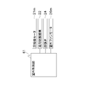
- FIG. 4 is a control block diagram of the indoor control unit 62. As shown in FIG. The indoor control unit 62 is connected to the indoor fan motor 32m, the first flap motor 35a1m, the second flap motor 35a2m, and various sensors (not shown) so as to be able to transmit and receive control signals.
- the indoor control unit 62 is configured to be able to receive various signals transmitted from a remote controller (not shown) for operating the air conditioner 1 .
- the various signals include, for example, signals for instructing start and stop of air-conditioning operation and signals for various settings.
- Signals related to various settings include, for example, signals related to set temperature and set humidity.
- the indoor control unit 62 exchanges various signals with the outdoor control unit 61 of the outdoor unit 2, which will be described later, via a communication line.
- the indoor controller 62 and the outdoor controller 61 cooperate to perform the air conditioning operation.
- the indoor controller 62 executes the first control.
- the first control is an operation that can ensure a reaching distance of the airflow blown out from the blowout port 39b even during low-load operation. Details of the cooling operation, the heating operation, and the first control will be described later.
- the indoor control unit 62 and the outdoor control unit 61 are referred to as the control unit 60 when describing the state in which they are functioning in cooperation.
- the indoor control unit 62 has a control arithmetic device and a storage device (both not shown).
- the control arithmetic device is a processor such as a CPU or GPU.
- the storage device is a storage medium such as RAM, ROM and flash memory.
- the control arithmetic device reads a program stored in the storage device and performs predetermined arithmetic processing according to the program, thereby controlling the operation of each device that constitutes the indoor unit 3 . Further, the control arithmetic device can write the arithmetic result to the storage device and read the information stored in the storage device according to the program.
- Outdoor Unit The outdoor unit 2 is installed outside the target space SP, for example, although not limited thereto.
- the outdoor unit 2 mainly includes a compressor 21, a flow direction switching mechanism 22, an outdoor heat exchanger 23, an expansion valve 24, an accumulator 25, an outdoor fan 26, a liquid closing valve 27, and a gas closing valve 28. , a suction pipe 10a, a discharge pipe 10b, a first gas refrigerant pipe 10c, a liquid refrigerant pipe 10d, a second gas refrigerant pipe 10e, an outdoor controller 61, and various sensors (not shown).
- the suction pipe 10 a connects the flow direction switching mechanism 22 and the suction end of the compressor 21 .
- the discharge pipe 10 b connects the discharge end of the compressor 21 and the flow direction switching mechanism 22 .
- the first gas refrigerant pipe 10 c connects the flow direction switching mechanism 22 and the gas side end of the outdoor heat exchanger 23 .
- the liquid refrigerant pipe 10 d connects the liquid side end of the outdoor heat exchanger 23 and the liquid refrigerant communication pipe 41 .
- a liquid shut-off valve 27 is provided at the connection between the liquid refrigerant pipe 10d and the liquid refrigerant communication pipe 41 .
- An expansion valve 24 is provided in the liquid refrigerant pipe 10d.
- the second gas refrigerant pipe 10 e connects the flow direction switching mechanism 22 and the gas refrigerant communication pipe 42 .
- a gas shut-off valve 28 is provided at the connecting portion of the second gas refrigerant pipe 10 e with the gas refrigerant communication pipe 42 .
- the liquid shutoff valve 27 and the gas shutoff valve 28 are manually opened and closed valves.
- the compressor 21 is a device that compresses and discharges refrigerant using a compression mechanism 21a.
- Compressor 21 pressurizes low-pressure refrigerant in the refrigeration cycle to high pressure in the refrigeration cycle.
- the compressor 21 is, for example, a volumetric compressor such as a rotary type or a scroll type, although the type is not limited.
- a compression mechanism 21a of the compressor 21 is driven by a compressor motor 21m.
- the compressor motor 21m is a variable speed inverter motor.
- the outdoor controller 61 controls the rotation speed of the compressor motor 21m.
- the flow direction switching mechanism 22 is a mechanism for switching the flow direction of the refrigerant in the refrigerant circuit 10 .
- the flow direction switching mechanism 22 is a four-way switching valve.
- the flow direction switching mechanism 22 is switched between the first state and the second state by the outdoor control section 61 .
- the flow direction switching mechanism 22 communicates the suction pipe 10a with the second gas refrigerant pipe 10e and the discharge pipe 10b with the first gas refrigerant pipe 10c, as indicated by solid lines in FIG.
- the flow direction switching mechanism 22 communicates the intake pipe 10a with the first gas refrigerant pipe 10c and the discharge pipe 10b with the second gas refrigerant pipe 10e, as indicated by broken lines in FIG.
- the outdoor heat exchanger 23 causes heat exchange between the refrigerant flowing through the outdoor heat exchanger 23 and the air outside the target space SP, which is the heat source air.
- the structure of the outdoor heat exchanger 23 is not limited, for example, it is a cross-fin type fin-and-tube heat exchanger composed of a heat transfer tube (not shown) and a large number of fins (not shown). is.
- the expansion valve 24 is an expansion valve capable of adjusting the degree of opening for adjusting the flow rate of the refrigerant.
- the expansion valve 24 is provided in the liquid refrigerant pipe 10d.
- the opening degree of the expansion valve 24 is controlled by the outdoor controller 61 .
- the accumulator 25 separates the inflowing refrigerant into gas refrigerant and liquid refrigerant.
- the accumulator 25 is provided in the intake pipe 10a.
- the refrigerant flowing into the accumulator 25 is divided into gas refrigerant and liquid refrigerant, and the gas refrigerant flows into the compressor 21 .
- the outdoor fan 26 is a fan for sucking the heat source air into the outdoor unit 2 for heat exchange, and then blowing it out of the outdoor unit 2 again.
- the outdoor fan 26 is, but not limited to, an axial fan such as a propeller fan driven by an outdoor fan motor 26m.
- the outdoor fan motor 26m is a variable speed inverter motor. The rotation speed of the outdoor fan motor 26m is controlled by the outdoor controller 61. FIG.
- Outdoor Control Unit 61 controls the rotation speed of the compressor motor 21m, the state of the flow direction switching mechanism 22, the opening degree of the expansion valve 24, and the rotation speed of the outdoor fan motor 26m.
- FIG. 5 is a control block diagram of the outdoor control unit 61.
- the outdoor control unit 61 is connected to the compressor motor 21m, the flow direction switching mechanism 22, the expansion valve 24, and the outdoor fan motor 26m so that control signals can be transmitted and received.
- the refrigerant discharged from the compressor 21 flows through the refrigerant circuit 10 in order of the outdoor heat exchanger 23, the expansion valve 24, and the indoor heat exchanger 31, and returns to the suction end of the compressor 21.
- the outdoor heat exchanger 23 functions as a condenser
- the indoor heat exchanger 31 functions as an evaporator.
- control unit 60 controls the rotational speeds of the compressor motor 21m, the outdoor fan motor 26m, and the indoor fan motor 32m, the rotation speed of the expansion valve 24, and the like, based on the measurement values of various sensors, the transmission from the operation remote control, and the like. It controls the degree of opening and the posture of the flap 35 .
- the control unit 60 starts controlling each device of the air conditioner 1 .
- the indoor controller 62 drives the indoor fan motor 32m.
- the outdoor control unit 61 switches the flow direction switching mechanism 22 to the second state, drives the compressor motor 21m and the outdoor fan motor 26m, and adjusts the opening degree of the expansion valve 24 .
- the refrigerant discharged from the compressor 21 flows through the refrigerant circuit 10 in the order of the indoor heat exchanger 31, the expansion valve 24, and the outdoor heat exchanger 23, and returns to the suction end of the compressor 21.
- the indoor heat exchanger 31 functions as a condenser
- the outdoor heat exchanger 23 functions as an evaporator.
- control unit 60 controls the rotational speeds of the compressor motor 21m, the outdoor fan motor 26m, and the indoor fan motor 32m, the rotation speed of the expansion valve 24, and the like, based on the measured values of various sensors, the transmission from the operation remote control, and the like. It controls the degree of opening and the posture of the flap 35 .
- the first control is executed in parallel with the air conditioning operation.
- the indoor control unit 62 controls the flap 35 so as to narrow the ventilation passage 40 formed by the flap 35 and the outlet 39b.
- the posture of The low-load air-conditioning operation is an operation in which the load of the air-conditioning operation is low. or the rotation speed of the indoor fan motor 32m becomes a low rotation speed lower than a predetermined rotation speed.
- FIG. 6 is a flow chart showing the control flow of the first control.
- the control flow shown in FIG. 6 starts when the low-load air conditioning operation starts.
- the indoor control unit 62 detects that the low-load air conditioning operation has started, for example, by detecting the intake air temperature (the temperature of the air sucked from the intake port 39a) and the power consumption of the fan motor 32m.
- step S100 the indoor control unit 62 acquires the air volume Vf of the airflow generated by the indoor fan 32, and proceeds to step S110.
- the indoor control unit 62 can calculate the air volume Vf of the airflow generated by the indoor fan 32 based on the rotation speed of the indoor fan motor 32m.
- the first air volume Vth1 is set to an air volume that does not allow the airflow blown out from the indoor unit 3 to reach a sufficient distance.
- the first air volume Vth1 is set, for example, to an air volume at which the velocity of the airflow blown out from the air outlet 39b is 2.8 m/s.
- step S120 the indoor control unit 62 controls the attitude of the flap 35 to a preset attitude according to the air volume Vf so as to narrow the ventilation path 40 formed by the flap 35 and the air outlet 39b, and proceeds to step S130. move on.
- the preset attitude of the flap 35 is such that even if the airflow generated by the indoor fan 32 is less than or equal to the first air volume Vth1, the airflow blown out from the outlet 39b reaches a sufficient distance.
- the indoor control unit 62 adjusts the attitude of the flap 35 so that the wind speed of the airflow blown out from the air outlet 39b is 2.8 m or more and 5 m or less per second. to control.
- the indoor control unit 62 controls the posture of the flap 35 so that the amount of restriction of the ventilation passage 40 increases as the air volume Vf decreases.
- step S130 the indoor control unit 62 acquires the air volume Vf of the airflow generated by the indoor fan 32, and proceeds to step S140.
- step S140 the indoor control unit 62 determines whether the air volume Vf is equal to or greater than a second air volume Vth2 set in advance, and if it determines that the air volume Vf is equal to or greater than the second air volume Vth2 (Yes), the process proceeds to step S150. If it is determined that the air volume Vf is not equal to or less than the second air volume Vth2 (No), the process proceeds to step S130.
- the second air volume Vth2 is an air volume larger than the first air volume Vth1.
- the second air volume Vth2 is an air volume that can reduce the amount of restriction of the ventilation passage 40 by the flap 35 .
- the second air volume Vth2 is set to an air volume that allows the airflow to reach a required distance with the normal throttling amount of the ventilation passage 40 .
- the second air volume Vth2 is set, for example, to an air volume in which the wind speed of the airflow blown out from the air outlet 39b is in the range of 2.8 m or more and 5 m or less per second.
- step S150 the indoor control unit 62 restores the posture of the flap 35 to the state before the ventilation passage 40 is narrowed in step S120, and proceeds to step S100.
- the indoor control unit 62 ends this control flow when the indoor control unit 62 ends the low-load air conditioning operation.
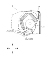
- FIG. 7 is a cross-sectional view of the indoor unit 3 for explaining the attitude of the flap 35 during the first control.
- the attitude of the flap 35 when the first control is not executed is indicated by a dashed line
- the attitude of the flap 35 when the first control is being executed is indicated by a solid line.
- the indoor control unit 62 rotates the second flap 35a2 about the rotation axis O2 to perform air conditioning.
- the apparatus 1 is rotated by a predetermined angle counterclockwise when viewed from the right side to assume a posture a1.
- the indoor control unit 62 rotates the first flap 35a1 about the rotation axis O1 clockwise by a predetermined angle as viewed from the right side of the air conditioner 1 to take the posture b1.
- the ventilation passage 40 is narrowed compared to the case where the indoor fan 32 generates an airflow larger than the first air volume Vth1.
- the indoor control unit 62 causes the second flap 35a2 in the attitude a1 to move about the rotation axis O2. Then, the air conditioner 1 is rotated counterclockwise by a predetermined angle as viewed from the right side to assume a posture a2. At this time, the indoor control unit 62 does not change the posture of the first flap 35a1. Thereby, compared with the case where the indoor fan 32 produces
- the indoor control unit 62 controls the attitude of the flap 35 so that the amount of restriction of the ventilation passage 40 increases as the air volume Vf decreases.
- the indoor control unit 62 controls the attitude of the flap 35 so that the throttle amount of the air passage 40 increases in two stages.
- the attitude of the flap 35 may be controlled to increase the amount.
- the air current after passing through the ventilation passage 40 can be increased compared to before starting the first control. Therefore, according to the indoor unit 3, even when the indoor fan 32 is rotated at a low rotational speed during low-load operation, the reaching distance of the airflow blown out from the outlet 39b can be ensured.
- the indoor controller 62 controls the attitude of the flap 35 so that the smaller the air volume generated by the indoor fan 32, the greater the throttle amount of the ventilation passage 40 .
- the indoor control unit 62 controls the attitude of the flap 35 so that the amount of constriction of the air passage 40 is increased step by step.
- the attitude of the flap 35 can be easily controlled.
- the outer diameter of the indoor fan 32 is 115 mm or more.
- the indoor fan 32 is a cross-flow fan with a large outer diameter of 115 mm or more, it is possible to ensure the reaching distance of the airflow blown out from the outlet 39b during low-load operation.
- the outer peripheral diameter of the indoor fan 32 is 115 mm or more and 150 mm or less, and the wind speed of the airflow blown out from the air outlet 39b when the first control is executed is 2.8 m or more and 5 m or less per second.
- FIG. 8 is a cross-sectional view of the indoor unit 3 showing how the indoor control unit 62 according to Modification A changes the posture of the flap 35 in the first control during cooling operation.
- the indoor control unit 62 In the first control during the cooling operation, the indoor control unit 62 according to the modification A directs the airflow blown out from the blowout port 39b upward in the vertical direction as it moves away from the flap 35, as indicated by the arrow in FIG. to control the attitude of the flap 35.
- the indoor control unit 62 controls the posture of the first flap 35a1 so that most of the airflow blown out from the outlet 39b flows along the surface of the second flap 35a2. Further, the indoor control unit 62 controls the posture of the second flap 35a2 so that the main surface faces upward at a predetermined angle as it goes forward from the rotation axis O2. As a result, the airflow flowing along the surface of the second flap 35a2 moves vertically upward as it separates from the flap 35 due to the Coanda effect.
- the indoor unit 3 according to the modification A the phenomenon that dew condensation occurs on the surface of the casing 39 due to the direct contact of the airflow blown out from the blowout port 39b during the cooling operation with the casing 39 is suppressed. be done.
- FIG. 9 is a cross-sectional view of the indoor unit 3 showing how the indoor control unit 62 according to Modification B changes the posture of the flap 35 in the first control during the heating operation.
- the indoor control unit 62 controls the posture of the first flap 35a1 so that the main surface hangs down substantially downward of the rotation axis O1. Further, the indoor control unit 62 controls the posture of the second flap 35a2 so that the main surface hangs down substantially downward of the rotation axis O2. As a result, the airflow blown out from the air outlet 39b and passing through the ventilation passage 40 is directed downward in the vertical direction. The phenomenon that people feel cold (feeling of draft) due to direct contact with the airflow blown out from is suppressed.
- FIG. 10 is a flowchart showing the control flow of the first control executed by the indoor control unit 62 in the air conditioner 1 according to Modification C.
- FIG. 10 is a flowchart showing the control flow of the first control executed by the indoor control unit 62 in the air conditioner 1 according to Modification C.
- step S200 the indoor control unit 62 acquires the rotation speed Rm of the indoor fan motor 32m, and proceeds to step S210.
- step S210 the indoor control unit 62 determines whether the rotation speed Rm is equal to or lower than a preset first rotation speed Rth1. If it is determined that the rotation speed Rm is equal to or lower than the first rotation speed Rth1 (Yes), Proceeding to S220, if it is determined that the number of revolutions Rm is not equal to or less than the first number of revolutions Rth1 (No), the process proceeds to step S200.
- the first rotation speed Rth1 is set to a rotation speed at which the airflow blown out from the indoor unit 3 cannot reach a sufficient distance.
- the first rotation speed Rth1 is set, for example, to a rotation speed at which the wind velocity of the airflow blown out from the outlet 39b is 2.8 m/s.
- step S220 the indoor control unit 62 controls the attitude of the flap 35 to a preset attitude according to the rotational speed Rm so as to narrow the air passage 40 formed by the flap 35 and the air outlet 39b. proceed to
- the preset posture of the flap 35 is a posture that allows the airflow blown out from the outlet 39b to reach a sufficient distance even if the airflow generated by the indoor fan 32 is the first rotation speed Rth1 or less. .
- the indoor control unit 62 adjusts the attitude of the flap 35 so that the wind speed of the airflow blown out from the air outlet 39b is 2.8 m or more and 5 m or less per second. to control.
- the indoor control unit 62 controls the attitude of the flap 35 so that the amount of restriction of the air passage 40 increases as the rotational speed Rm decreases.
- step S230 the indoor control unit 62 acquires the rotation speed Rm of the indoor fan motor 32m, and proceeds to step S240.
- step S240 the indoor control unit 62 determines whether the rotation speed Rm is equal to or higher than a second rotation speed Rth2 set in advance. If it is determined that the rotation speed Rm is equal to or higher than the second rotation speed Rth2 (Yes) Proceeding to S250, if it is determined that the number of revolutions Rm is not equal to or less than the second number of revolutions Rth2 (No), the process proceeds to step S230.
- the second rotation speed Rth2 is a rotation speed higher than the first rotation speed Rth1.
- the second rotation speed Rth2 is an air volume that can reduce the amount of throttling of the ventilation passage 40 by the flap 35 .
- the second rotation speed Rth2 is set to an air volume that allows the airflow to reach a required distance with the normal throttle amount of the ventilation passage 40 .
- the second rotation speed Rth2 is set, for example, to a rotation speed at which the wind speed of the airflow blown out from the blower outlet 39b is in the range of 2.8 m/s or more and 5 m/s or less.
- step S250 the indoor control unit 62 restores the posture of the flap 35 to the state before the ventilation passage 40 is narrowed in step S220, and proceeds to step S200.
- the indoor control unit 62 ends this control flow when the indoor control unit 62 ends the low-load air conditioning operation.
- the indoor control unit 62 sets the second flap 35a2 to the posture a1, and the first flap Let 35a1 be posture b1 (see FIG. 7). Thereby, compared with the case where the rotation speed of the indoor fan 32 is larger than 1st rotation speed, the ventilation path 40 is throttled.
- the indoor control unit 62 changes the second flap 35a2 in the posture a1 to the posture a2. , the posture of the first flap 35a1 is not changed. As a result, the ventilation passage 40 is narrowed compared to the case where the indoor fan 32 is rotating at the rotation speed Rm1.
Landscapes
- Engineering & Computer Science (AREA)
- Chemical & Material Sciences (AREA)
- Combustion & Propulsion (AREA)
- Mechanical Engineering (AREA)
- General Engineering & Computer Science (AREA)
- Physics & Mathematics (AREA)
- Fluid Mechanics (AREA)
- Air Conditioning Control Device (AREA)
- Air-Conditioning Room Units, And Self-Contained Units In General (AREA)
Abstract
低負荷運転時でも、吹出口から吹き出される気流の到達距離を確保できる室内機を提案する。室内機(3)は、室内ファン(32)と、ケーシング(39)と、フラップ(35)と、室内制御部(62)とを備える。室内ファン(32)は、円筒状のクロスフローファンである。ケーシング(39)は、室内ファン(32)を収容し、室内ファン(32)が生成する気流を吹き出す吹出口(39b)が形成されている。フラップ(35)は、吹出口(39b)を開閉する。室内制御部(62)は、フラップ(35)の姿勢を制御する。室内制御部(62)は、空調運転の負荷が低い低負荷空調運転時に室内ファン(32)が生成する風量(Vf)または室内ファン(32)の回転数(Rm)が所定値以下になると、フラップ(35)と吹出口(39b)とが形成する通風路(40)を絞るようにフラップ(35)の姿勢を制御する、第1制御を実行する。
Description
室内機に関する。
特許文献1(特開2002-195595号公報)は、円筒状のクロスフローファンと、クロスフローファンを収容し、クロスフローファンが生成する気流を吹き出す吹出口が形成されたケーシングとを備える、空調装置の室内機を開示する。
空調装置の分野では、送風性能の向上を目的としてクロスフローファンの大径化が図られているが、クロスフローファンが大型化すると生成された気流を吹き出すためにケーシングに形成された吹出口も大きくなる。このため、低負荷運転時に低回転数でクロスフローファンを回転させると、吹出口から吹き出す気流の風速を確保できず、生成された気流を空調装置から離れた位置まで到達させることが困難になるという問題がある。
本開示は、低負荷運転時でも、吹出口から吹き出される気流の到達距離を確保できる室内機を提案する。
第1観点の室内機は、空調装置の室内機である。室内機は、クロスフローファンと、ケーシングと、フラップと、制御部とを備える。クロスフローファンは、円筒状のファンである。ケーシングは、クロスフローファンを収容し、クロスフローファンが生成する気流を吹き出す吹出口が形成されている。フラップは、吹出口を開閉する。制御部は、フラップの姿勢を制御する。制御部は、空調運転の負荷が低い低負荷空調運転時にクロスフローファンが生成する気流の風量またはクロスフローファンの回転数が所定値以下になると、フラップと吹出口とが形成する通風路を絞るようにフラップの姿勢を制御する、第1制御を実行する。
本室内機によれば、低負荷運転時に低回転数でクロスフローファンを回転させた場合であっても、吹出口から吹き出される気流の到達距離を確保できる。
第2観点の室内機は、第1観点の室内機であって、制御部が、第1制御において、風量または回転数が小さいほど通風路の絞り量が増加するようにフラップの姿勢を制御する。
本室内機によれば、低負荷運転時にクロスフローファンの回転数がさらに低下した場合であっても、吹出口から吹き出される気流の到達距離を確保できる。
第3観点の室内機は、第2観点の室内機であって、制御部が、第1制御において、段階的に通風路の絞り量が増加するようにフラップの姿勢を制御する。
本室内機によれば、容易にフラップの姿勢を制御できる。
第4観点の室内機は、第1観点から第3観点のいずれかの室内機であって、クロスフローファンの外周直径が、115mm以上である。
本室内機によれば、外周直径が115mm以上と大径なクロスフローファンであっても、低負荷運転時において吹出口から吹き出される気流の到達距離を確保できる。
第5観点の室内機は、第1観点から第4観点のいずれかの室内機であって、壁掛け型である。クロスフローファンは、長手方向が水平方向に沿う姿勢でケーシングに収容される。吹出口は、鉛直方向において、クロスフローファンの下方に形成される。制御部は、暖房運転中の第1制御において、吹出口から吹き出される気流が、鉛直方向において吹出口の下方へ向かうようにフラップの姿勢を制御する。
本室内機によれば、暖房運転中に吹出口から吹き出される気流が、直接当たることにより人が寒さ(ドラフト感)を感じる現象が抑制される。
第6観点の室内機は、第1観点から第5観点のいずれかの室内機であって、壁掛け型である。クロスフローファンは、長手方向が水平方向に沿う姿勢でケーシングに収容される。吹出口は、鉛直方向において、クロスフローファンの下方に形成される。制御部は、冷房運転中の第1制御において、吹出口から吹き出される気流が、フラップから離れるにしたがって鉛直方向上方へ向かうようにフラップの姿勢を制御する。
本室内機によれば、冷房運転中に吹出口から吹き出される気流がケーシングに直接当たることでケーシングの表面に結露が発生する現象(露付き)が抑制される。
第7観点の室内機は、第1観点から第6観点のいずれかの室内機であって、クロスフローファンの外周直径は、115mm以上150mm以下である。第1制御が実行されるときに吹出口から吹き出される気流の風速は、毎秒2.8m以上5m以下である。
(1)全体構成
空調装置1は、蒸気圧縮式の冷凍サイクルを利用して、対象空間SPにおける冷房運転、及び暖房運転を含む空調運転)を実現する装置である。
空調装置1は、蒸気圧縮式の冷凍サイクルを利用して、対象空間SPにおける冷房運転、及び暖房運転を含む空調運転)を実現する装置である。
図1は、空調装置1の概略構成図である。空調装置1は、図1に示すように、主として、室外機2と、室内機3と、液冷媒連絡管41と、ガス冷媒連絡管42とを有する。本実施形態では、空調装置1は、室内機3を1台だけ有するが、空調装置1は、互いに並列に接続される複数の室内機3を有してもよい。液冷媒連絡管41及びガス冷媒連絡管42は、いずれも室外機2と室内機3とを接続する配管である。図2は、空調装置1の冷媒回路10を示す図である。冷媒回路10は、室外機2と室内機3とが、液冷媒連絡管41及びガス冷媒連絡管42を介して接続されることで構成される。冷媒回路10は、主として、室外機2の圧縮機21、流向切換機構22、室外熱交換器23、及び膨張弁24と、室内機3の室内熱交換器31と、を含む。
なお、以下の説明で用いる、上、下、前、後、左、右の各方向は、各図に矢印で示す方向である。
(2)詳細構成
(2-1)室内機
室内機3は、対象空間SP内に設置されている。室内機3は、対象空間SPの壁に掛けて設置される壁掛け型のユニットである。
(2-1)室内機
室内機3は、対象空間SP内に設置されている。室内機3は、対象空間SPの壁に掛けて設置される壁掛け型のユニットである。
図3は、室内機3の断面図である。室内機3は、主として、室内熱交換器31と、室内ファン32と、液冷媒管33と、ガス冷媒管34と、フラップ35と、ケーシング39と、室内制御部62と、各種センサ(図示省略)とを備える。
(2-1-1)ケーシング
ケーシング39は、室内ファン32をはじめとした室内機3の各機器を収容する。ケーシング39は、左右方向に長い略直方体形状である。ケーシング39は、上部に対象空間SPの空気を吸入するための吸込口39aが形成されている。ケーシング39は、下部に室内ファン32が生成する気流を吹き出すための吹出口39bが形成されている。吸込口39a及び吹出口39bは、どちらも左右方向に伸びる2つの辺及び前後方向に伸びる2つの辺により形成される略矩形状の孔である。
ケーシング39は、室内ファン32をはじめとした室内機3の各機器を収容する。ケーシング39は、左右方向に長い略直方体形状である。ケーシング39は、上部に対象空間SPの空気を吸入するための吸込口39aが形成されている。ケーシング39は、下部に室内ファン32が生成する気流を吹き出すための吹出口39bが形成されている。吸込口39a及び吹出口39bは、どちらも左右方向に伸びる2つの辺及び前後方向に伸びる2つの辺により形成される略矩形状の孔である。
(2-1-2)室内熱交換器
室内熱交換器31は、室内熱交換器31を流れる冷媒と、吸込口39aから吸い込まれた対象空間SPの空気との間で熱交換を行わせる。室内熱交換器31は、複数の伝熱フィン31aと、複数の伝熱管31bとを有するクロスフィン式のフィン・アンド・チューブ型熱交換器である。室内熱交換器31は、液側端に液冷媒管33が接続され、ガス側端にガス冷媒管34が接続されている。
室内熱交換器31は、室内熱交換器31を流れる冷媒と、吸込口39aから吸い込まれた対象空間SPの空気との間で熱交換を行わせる。室内熱交換器31は、複数の伝熱フィン31aと、複数の伝熱管31bとを有するクロスフィン式のフィン・アンド・チューブ型熱交換器である。室内熱交換器31は、液側端に液冷媒管33が接続され、ガス側端にガス冷媒管34が接続されている。
(2-1-3)室内ファン
室内ファン32は、対象空間SPの空気を室内機3内に吸入し熱交換を行わせた後、再び対象空間SPに吹き出すためのファンである。室内ファン32は、ファンモータ32mにより駆動される、円筒状のクロスフローファンである。
室内ファン32は、対象空間SPの空気を室内機3内に吸入し熱交換を行わせた後、再び対象空間SPに吹き出すためのファンである。室内ファン32は、ファンモータ32mにより駆動される、円筒状のクロスフローファンである。
室内ファン32は、長手方向が水平方向(図1の左右方向)に沿う姿勢でケーシング39に収容されている。ケーシング39の吹出口39bは、鉛直方向(図1、図3の上下方向)において、室内ファン32の下方に形成されている。室内ファンモータ32mは、回転数可変のインバータモータである。室内ファンモータ32mの回転数は、室内制御部62により制御される。室内ファン32は、送風性能を確保するために、外周径(図3のD)が115mm以上であることが好ましい。
(2-1-4)フラップ
フラップ35は、吹出口39bの開放・閉塞、及び吹出口39bから吹き出される気流の方向を調整する板状部材である。フラップ35は、第1フラップ35a1と、第2フラップ35a2とを有する。
フラップ35は、吹出口39bの開放・閉塞、及び吹出口39bから吹き出される気流の方向を調整する板状部材である。フラップ35は、第1フラップ35a1と、第2フラップ35a2とを有する。
第1フラップ35a1は、吹出口39bの開放・閉塞と、吹出口39bから吹き出される気流の方向を調整する。第1フラップ35a1は、吹出口39bと略同じ矩形状の板状部材である。第1フラップ35a1は、吹出口39bの後側の辺の近傍に設けられた回転軸O1を軸として回転可能に取り付けられる。第1フラップ35a1は、回転軸O1を中心に回転することにより、主面によって吹出口39bを閉塞した状態と、主面が回転軸O1の略下方に向かって垂れ下がった状態との間で姿勢が変化する。第1フラップ35a1の姿勢は、室内制御部62が第1フラップモータ35a1m(図示省略)を介して制御する。
第2フラップ35a2は、コアンダ効果によって吹出口39bから吹き出される気流の方向を調整する。第2フラップ35a2は、左右方向における長さが、吹出口39bの左右方向における長さと略同じで、所定の幅を有する矩形の板状部材である。第2フラップ35a2は、吹出口39bの前側の辺の近傍に設けられた回転軸O2を軸として回転可能に取り付けられる。第2フラップ35a2は、回転軸O2を中心に回転することにより、主面が回転軸O2の略下方に向かって垂れ下がった状態と、回転軸O2から前方に向かうにつれて主面が所定の角度で上方に向かう状態との間で姿勢が変化する。第2フラップ35a2の姿勢は、室内制御部62が第2フラップモータ35a2m(図示省略)を介して制御する。
以下では、フラップ35と吹出口39bとが形成する領域、より詳細には、第1フラップ35a1と第2フラップ35a2とにより挟まれ吹出口39bから吹き出された気流が通過する領域のことを、便宜上、通風路40とよぶ。
(2-1-5)液冷媒管及びガス冷媒管
液冷媒管33は、一端に室内熱交換器31が接続され、他端に液冷媒連絡管41が接続された配管である。
液冷媒管33は、一端に室内熱交換器31が接続され、他端に液冷媒連絡管41が接続された配管である。
ガス冷媒管34は、一端に室内熱交換器31が接続され、他端にガス冷媒連絡管42が接続された配管である。
(2-1-6)室内制御部
室内制御部62は、室内ファンモータ32mの回転数、及びフラップ35の姿勢を制御する。
室内制御部62は、室内ファンモータ32mの回転数、及びフラップ35の姿勢を制御する。
図4は、室内制御部62の制御ブロック図である。室内制御部62は、室内ファンモータ32m、第1フラップモータ35a1m、第2フラップモータ35a2m、及び各種センサ(図示省略)と制御信号を送受信可能に接続されている。
室内制御部62は、空調装置1の操作用リモコン(図示省略)から送信される各種信号を、受信可能に構成されている。各種信号には、例えば、空調運転の開始及び停止を指示する信号や、各種設定に関する信号が含まれる。各種設定に関する信号には、例えば、設定温度や設定湿度に関する信号が含まれる。
室内制御部62は、通信回線を介し、後述する室外機2の室外制御部61との間で各種信号等のやりとりを行う。室内制御部62及び室外制御部61は、協働して空調運転を実行する。室内制御部62は、第1制御を実行する。第1制御は、低負荷運転時でも、吹出口39bから吹き出される気流の到達距離を確保できる運転である。冷房運転、暖房運転、及び第1制御の詳細については、後述する。以下の説明では、室内制御部62と室外制御部61とが協働して機能している状態を説明する際には、制御部60とよぶ。
室内制御部62は、制御演算装置及び記憶装置(いずれも図示省略)を有する。制御演算装置は、CPUやGPU等のプロセッサである。記憶装置は、RAM、ROM及びフラッシュメモリ等の記憶媒体である。制御演算装置は、記憶装置に記憶されているプログラムを読み出し、プログラムに従って所定の演算処理を行うことで、室内機3を構成する各機器の動作を制御する。また、制御演算装置は、プログラムに従って、演算結果を記憶装置に書き込んだり、記憶装置に記憶されている情報を読み出したりすることができる。
(2-2)室外機
室外機2は、限定するものではないが、例えば、対象空間SPの外部に設置されている。
室外機2は、限定するものではないが、例えば、対象空間SPの外部に設置されている。
室外機2は、主として、圧縮機21と、流向切換機構22と、室外熱交換器23と、膨張弁24と、アキュムレータ25と、室外ファン26と、液閉鎖弁27と、ガス閉鎖弁28と、吸入管10aと、吐出管10bと、第1ガス冷媒管10cと、液冷媒管10dと、第2ガス冷媒管10eと、室外制御部61と、各種センサ(図示省略)とを有する。吸入管10aは、流向切換機構22と圧縮機21の吸入端とを接続する。吐出管10bは、圧縮機21の吐出端と流向切換機構22とを接続する。第1ガス冷媒管10cは、流向切換機構22と室外熱交換器23のガス側端とを接続する。液冷媒管10dは、室外熱交換器23の液側端と液冷媒連絡管41とを接続する。液冷媒管10dの液冷媒連絡管41との接続部には、液閉鎖弁27が設けられている。液冷媒管10dには、膨張弁24が設けられている。第2ガス冷媒管10eは、流向切換機構22とガス冷媒連絡管42とを接続する。第2ガス冷媒管10eのガス冷媒連絡管42との接続部には、ガス閉鎖弁28が設けられている。液閉鎖弁27及びガス閉鎖弁28は、手動で開閉される弁である。
(2-2-1)圧縮機
圧縮機21は、圧縮機構21aにより冷媒を圧縮して吐出する機器である。圧縮機21は、冷凍サイクルにおける低圧の冷媒を、冷凍サイクルにおける高圧にまで加圧する。圧縮機21は、タイプを限定するものではないが、例えば、ロータリ式やスクロール式等の容積圧縮機である。圧縮機21の圧縮機構21aは、圧縮機モータ21mによって駆動される。圧縮機モータ21mは、回転数可変のインバータモータである。圧縮機モータ21mの回転数は、室外制御部61により制御される。
圧縮機21は、圧縮機構21aにより冷媒を圧縮して吐出する機器である。圧縮機21は、冷凍サイクルにおける低圧の冷媒を、冷凍サイクルにおける高圧にまで加圧する。圧縮機21は、タイプを限定するものではないが、例えば、ロータリ式やスクロール式等の容積圧縮機である。圧縮機21の圧縮機構21aは、圧縮機モータ21mによって駆動される。圧縮機モータ21mは、回転数可変のインバータモータである。圧縮機モータ21mの回転数は、室外制御部61により制御される。
(2-2-2)流向切換機構
流向切換機構22は、冷媒回路10における冷媒の流向を切り換える機構である。本実施形態では、流向切換機構22は四路切換弁である。
流向切換機構22は、冷媒回路10における冷媒の流向を切り換える機構である。本実施形態では、流向切換機構22は四路切換弁である。
流向切換機構22は、室外制御部61によって第1状態と、第2状態との間で切換えらえる。流向切換機構22は、第1状態で、図2において実線で示されるように、吸入管10aを第2ガス冷媒管10eと連通させ、吐出管10bを第1ガス冷媒管10cと連通させる。流向切換機構22は、第2状態で、図2において破線で示されるように、吸入管10aを第1ガス冷媒管10cと連通させ、吐出管10bを第2ガス冷媒管10eと連通させる。
(2-2-3)室外熱交換器
室外熱交換器23は、室外熱交換器23を流れる冷媒と、熱源空気である対象空間SPの外部の空気との間で熱交換が行わせる。室外熱交換器23は、構造を限定するものではないが、例えば、伝熱管(図示省略)と多数のフィン(図示省略)とにより構成されるクロスフィン式のフィン・アンド・チューブ型熱交換器である。
室外熱交換器23は、室外熱交換器23を流れる冷媒と、熱源空気である対象空間SPの外部の空気との間で熱交換が行わせる。室外熱交換器23は、構造を限定するものではないが、例えば、伝熱管(図示省略)と多数のフィン(図示省略)とにより構成されるクロスフィン式のフィン・アンド・チューブ型熱交換器である。
(2-2-4)膨張弁
膨張弁24は、冷媒の流量を調節する開度調節が可能な膨張弁である。膨張弁24は、液冷媒管10dに設けられている。膨張弁24は、室外制御部61によって開度が制御される。
膨張弁24は、冷媒の流量を調節する開度調節が可能な膨張弁である。膨張弁24は、液冷媒管10dに設けられている。膨張弁24は、室外制御部61によって開度が制御される。
(2-2-5)アキュムレータ
アキュムレータ25は、流入する冷媒をガス冷媒と液冷媒とに分離する。アキュムレータ25は、吸入管10aに設けられる。アキュムレータ25に流入する冷媒は、ガス冷媒と液冷媒とに分けられ、ガス冷媒が圧縮機21へと流入する。
アキュムレータ25は、流入する冷媒をガス冷媒と液冷媒とに分離する。アキュムレータ25は、吸入管10aに設けられる。アキュムレータ25に流入する冷媒は、ガス冷媒と液冷媒とに分けられ、ガス冷媒が圧縮機21へと流入する。
(2-2-6)室外ファン
室外ファン26は、熱源空気を室外機2内に吸入し熱交換を行わせた後、再び室外機2の外部に吹き出すためのファンである。室外ファン26は、限定するものではないが、室外ファンモータ26mによって駆動されるプロペラファン等の軸流ファンである。室外ファンモータ26mは、回転数可変のインバータモータである。室外ファンモータ26mの回転数は、室外制御部61により制御される。
室外ファン26は、熱源空気を室外機2内に吸入し熱交換を行わせた後、再び室外機2の外部に吹き出すためのファンである。室外ファン26は、限定するものではないが、室外ファンモータ26mによって駆動されるプロペラファン等の軸流ファンである。室外ファンモータ26mは、回転数可変のインバータモータである。室外ファンモータ26mの回転数は、室外制御部61により制御される。
(2-2-7)室外制御部
室外制御部61は、圧縮機モータ21mの回転数、流向切換機構22の状態、膨張弁24の開度、及び室外ファンモータ26mの回転数を制御する。
室外制御部61は、圧縮機モータ21mの回転数、流向切換機構22の状態、膨張弁24の開度、及び室外ファンモータ26mの回転数を制御する。
図5は、室外制御部61の制御ブロック図である。室外制御部61は、圧縮機モータ21m、流向切換機構22、膨張弁24、及び室外ファンモータ26mと制御信号を送受信可能に接続されている。
室外制御部61は、制御演算装置及び記憶装置(いずれも図示省略)を有する。制御演算装置は、CPUやGPU等のプロセッサである。記憶装置は、RAM、ROM及びフラッシュメモリ等の記憶媒体である。制御演算装置は、記憶装置に記憶されているプログラムを読み出し、プログラムに従って所定の演算処理を行うことで、室外機2を構成する各機器の動作を制御する。また、制御演算装置は、プログラムに従って、演算結果を記憶装置に書き込んだり、記憶装置に記憶されている情報を読み出したりすることができる。
(3)空調装置の動作
制御部60が実行する冷房運転及び暖房運転、及び室内制御部62が実行する第1制御について説明をする。
制御部60が実行する冷房運転及び暖房運転、及び室内制御部62が実行する第1制御について説明をする。
(3-1)冷房運転
室内制御部62が操作用リモコンから送信される冷房運転の開始を指示する信号を受信すると、制御部60は、空調装置1の各機器の制御を開始する。具体的には、室内制御部62は、室内ファンモータ32mを駆動する。室外制御部61は、流向切換機構22を第1状態に切換え、圧縮機モータ21m及び室外ファンモータ26mを駆動し、膨張弁24の開度を調整する。
室内制御部62が操作用リモコンから送信される冷房運転の開始を指示する信号を受信すると、制御部60は、空調装置1の各機器の制御を開始する。具体的には、室内制御部62は、室内ファンモータ32mを駆動する。室外制御部61は、流向切換機構22を第1状態に切換え、圧縮機モータ21m及び室外ファンモータ26mを駆動し、膨張弁24の開度を調整する。
これにより、圧縮機21から吐出される冷媒は、冷媒回路10内を、室外熱交換器23、膨張弁24、室内熱交換器31の順に流れ、圧縮機21の吸入端へと戻る。この結果、室外熱交換器23は、凝縮器として機能し、室内熱交換器31は蒸発器として機能する。
冷房運転の間、制御部60は、各種センサの計測値や操作用リモコンから送信される等に基づき、圧縮機モータ21m、室外ファンモータ26m、及び室内ファンモータ32mの回転数、膨張弁24の開度、ならびにフラップ35の姿勢を制御する。
(3-2)暖房運転
室内制御部62が操作用リモコンから送信される暖房運転の開始を指示する信号を受信すると、制御部60は、空調装置1の各機器の制御を開始する。具体的には、室内制御部62は、室内ファンモータ32mを駆動する。室外制御部61は、流向切換機構22を第2状態に切換え、圧縮機モータ21m及び室外ファンモータ26mを駆動し、膨張弁24の開度を調整する。
室内制御部62が操作用リモコンから送信される暖房運転の開始を指示する信号を受信すると、制御部60は、空調装置1の各機器の制御を開始する。具体的には、室内制御部62は、室内ファンモータ32mを駆動する。室外制御部61は、流向切換機構22を第2状態に切換え、圧縮機モータ21m及び室外ファンモータ26mを駆動し、膨張弁24の開度を調整する。
これにより、圧縮機21から吐出される冷媒は、冷媒回路10内を、室内熱交換器31、膨張弁24、室外熱交換器23、の順に流れ、圧縮機21の吸入端へと戻る。この結果、室内熱交換器31は、凝縮器として機能し、室外熱交換器23は蒸発器として機能する。
暖房運転の間、制御部60は、各種センサの計測値や操作用リモコンから送信される等に基づき、圧縮機モータ21m、室外ファンモータ26m、及び室内ファンモータ32mの回転数、膨張弁24の開度、ならびにフラップ35の姿勢を制御する。
(3-3)第1制御
第1制御は、空調運転と並行して実行される。第1制御において室内制御部62は、低負荷空調運転時に室内ファン32が生成する気流の風量が所定値以下になると、フラップ35と吹出口39bとが形成する通風路40を絞るようにフラップ35の姿勢を制御する。低負荷空調運転とは、空調運転の負荷が低い運転であって、具体的には、圧縮機モータ21mの回転数が所定回転数よりも低い低回転数となったり、膨張弁24が全開となったり、室内ファンモータ32mの回転数が所定回転数よりも低い低回転数となったりする運転をいう。
第1制御は、空調運転と並行して実行される。第1制御において室内制御部62は、低負荷空調運転時に室内ファン32が生成する気流の風量が所定値以下になると、フラップ35と吹出口39bとが形成する通風路40を絞るようにフラップ35の姿勢を制御する。低負荷空調運転とは、空調運転の負荷が低い運転であって、具体的には、圧縮機モータ21mの回転数が所定回転数よりも低い低回転数となったり、膨張弁24が全開となったり、室内ファンモータ32mの回転数が所定回転数よりも低い低回転数となったりする運転をいう。
図6は、第1制御の制御フローを示すフローチャートである。図6に示された制御フローは、低負荷空調運転が始まると、開始される。室内制御部62は、例えば、吸込み空気温度(吸込口39aから吸入される空気の温度)やファンモータ32mの消費電力を検知することによって、低負荷空調運転が始まったことを検知する。
ステップS100において、室内制御部62は、室内ファン32が生成する気流の風量Vfを取得して、ステップS110に進む。
室内制御部62は、室内ファンモータ32mの回転数に基づいて室内ファン32が生成する気流の風量Vfを算出することができる。
ステップS110において、室内制御部62は、風量Vfがあらかじめ設定された第1風量Vth1以下であるかを判断し、風量Vfが第1風量Vth1以下であると判断すると(Yes)ステップS120に進み、風量Vfが第1風量Vth1以下でないと判断すると(No)ステップS100に進む。
第1風量Vth1は、室内機3から吹き出される気流を十分な距離まで到達させることができない風量に設定される。第1風量Vth1は、たとえば、吹出口39bから吹き出される気流の風速が毎秒2.8mとなる風量に設定される。
ステップS120において、室内制御部62は、フラップ35と吹出口39bとが形成する通風路40を絞るようにフラップ35の姿勢を風量Vfに応じてあらかじめ設定された姿勢に制御して、ステップS130に進む。
あらかじめ設定されたフラップ35の姿勢は、室内ファン32が生成する気流が第1風量Vth1以下であっても、吹出口39bから吹き出される気流を十分な距離まで到達させることができる姿勢である。例えば、室内制御部62は、ファン32の外周直径が115mm以上150mm以下である場合に、吹出口39bから吹き出される気流の風速が毎秒2.8m以上5m以下となるように、フラップ35の姿勢を制御する。室内制御部62は、風量Vfが小さいほど通風路40の絞り量が増加するようにフラップ35の姿勢を制御する。
ステップS130において、室内制御部62は、室内ファン32が生成する気流の風量Vfを取得して、ステップS140に進む。
ステップS140において、室内制御部62は、風量Vfがあらかじめ設定された第2風量Vth2以上であるかを判断し、風量Vfが第2風量Vth2以上であると判断すると(Yes)ステップS150に進み、風量Vfが第2風量Vth2以下でないと判断すると(No)ステップS130に進む。
第2風量Vth2は、第1風量Vth1よりも大きい風量である。第2風量Vth2は、フラップ35による通風路40の絞り量を緩和できる風量である。言い換えると、第2風量Vth2は、通常の通風路40の絞り量で気流を必要な距離まで到達させることができる風量に設定される。第2風量Vth2は、たとえば、吹出口39bから吹き出される気流の風速が毎秒2.8m以上5m以下の範囲となる風量に設定される。
ステップS150において、室内制御部62は、フラップ35の姿勢を、ステップS120において通風路40が絞られる前の状態に戻して、ステップS100に進む。
室内制御部62は、室内制御部62が低負荷空調運転を終了すると本制御フローを終了する。
(4)フラップの姿勢
次に、第1制御が実行された際のフラップ35の姿勢の変化について例を挙げて説明する。図7は、第1制御中におけるフラップ35の姿勢を説明するための室内機3の断面図である。図7は、第1制御が実行されていない時のフラップ35の姿勢を破線で示し、第1制御が実行されている時のフラップ35の姿勢を実線で示している。
次に、第1制御が実行された際のフラップ35の姿勢の変化について例を挙げて説明する。図7は、第1制御中におけるフラップ35の姿勢を説明するための室内機3の断面図である。図7は、第1制御が実行されていない時のフラップ35の姿勢を破線で示し、第1制御が実行されている時のフラップ35の姿勢を実線で示している。
第1制御が実行されて、室内ファン32が第1風量Vth1以下の風量Vf1を生成している場合には、室内制御部62は、第2フラップ35a2を、回転軸O2を中心にして、空調装置1を右側から見た反時計回りに所定角度回転させて姿勢a1とする。また、室内制御部62は、第1フラップ35a1を、回転軸O1を中心にして、空調装置1を右側から見て時計回りに所定角度回転させて姿勢b1とする。これにより、室内ファン32が第1風量Vth1より大きい気流を生成している場合と比較して、通風路40が絞られる。
さらに、第1制御が実行されて、室内ファン32が風量Vf1未満の風量Vf2を生成している場合には、室内制御部62は、姿勢a1である第2フラップ35a2を、回転軸O2を中心にして、空調装置1を右側から見て反時計回りに所定角度回転させて姿勢a2とする。この際、室内制御部62は、第1フラップ35a1の姿勢は変更しない。これにより、室内ファン32が風量Vf1の気流を生成している場合と比較して、通風路40が絞られる。
このようにして、室内制御部62は、第1制御において、風量Vfが小さいほど通風路40の絞り量が増加するようにフラップ35の姿勢を制御する。以上で説明した制御において、室内制御部62は、2段階で通風路40の絞り量が増加するようにフラップ35の姿勢を制御したが、室内制御部62は、無段階で通風路40の絞り量が増加するようにフラップ35の姿勢を制御してもよい。
(5)特徴
(5-1)
室内機3は、空調運転を行う空調装置1の室内機である。室内機3は、室内ファン32と、ケーシング39と、フラップ35と、室内制御部62とを備える。室内ファン32は、円筒状のクロスフローファンである。ケーシング39は、室内ファン32を収容し、室内ファン32が生成する気流を吹き出す吹出口39bが形成されている。フラップ35は、吹出口39bを開閉する。室内制御部62は、フラップ35の姿勢を制御する。室内制御部62は、空調運転の負荷が低い低負荷空調運転時に室内ファン32が生成する気流の風量Vfが所定の風量Vth1以下になると、フラップ35と吹出口39bとが形成する通風路40を絞るようにフラップ35の姿勢を制御する、第1制御を実行する。
(5-1)
室内機3は、空調運転を行う空調装置1の室内機である。室内機3は、室内ファン32と、ケーシング39と、フラップ35と、室内制御部62とを備える。室内ファン32は、円筒状のクロスフローファンである。ケーシング39は、室内ファン32を収容し、室内ファン32が生成する気流を吹き出す吹出口39bが形成されている。フラップ35は、吹出口39bを開閉する。室内制御部62は、フラップ35の姿勢を制御する。室内制御部62は、空調運転の負荷が低い低負荷空調運転時に室内ファン32が生成する気流の風量Vfが所定の風量Vth1以下になると、フラップ35と吹出口39bとが形成する通風路40を絞るようにフラップ35の姿勢を制御する、第1制御を実行する。
これにより、室内ファン32が生成する気流の風量Vfが、室内機3から吹き出される気流を十分な距離まで到達させることができない風量となった場合には、通風路40を通過した後の気流の速度を、第1制御を開始する前と比べて増加させることができる。したがって、室内機3によれば、低負荷運転時に低回転数で室内ファン32を回転させた場合であっても、吹出口39bから吹き出される気流の到達距離を確保できる。
(5-2)
室内制御部62は、第1制御において、室内ファン32が生成する気流の風量が小さいほど通風路40の絞り量が増加するようにフラップ35の姿勢を制御する。
室内制御部62は、第1制御において、室内ファン32が生成する気流の風量が小さいほど通風路40の絞り量が増加するようにフラップ35の姿勢を制御する。
これにより、低負荷運転時に室内ファン32の回転数がさらに低下した場合であっても、吹出口39bから吹き出される気流の到達距離を確保できる。
(5-3)
室内制御部62は、第1制御において、段階的に通風路40の絞り量が増加するようにフラップ35の姿勢を制御する。
室内制御部62は、第1制御において、段階的に通風路40の絞り量が増加するようにフラップ35の姿勢を制御する。
これにより、容易にフラップ35の姿勢を制御できる。
(5-4)
室内ファン32の外周直径は、115mm以上である。
室内ファン32の外周直径は、115mm以上である。
これにより、外周直径が115mm以上と大径なクロスフローファンが室内ファン32であっても、低負荷運転時において吹出口39bから吹き出される気流の到達距離を確保できる。
(5-5)
室内ファン32の外周直径は、115mm以上150mm以下であり、第1制御が実行されるときに吹出口39bから吹き出される気流の風速は、毎秒2.8m以上5m以下である。
室内ファン32の外周直径は、115mm以上150mm以下であり、第1制御が実行されるときに吹出口39bから吹き出される気流の風速は、毎秒2.8m以上5m以下である。
(6)変形例
(6-1)変形例A
第1制御において室内制御部62は、フラップ35を上述以外の姿勢に制御してもよい。図8は、変形例Aに係る室内制御部62が、冷房運転中の第1制御においてフラップ35の姿勢を変える様子を示した室内機3の断面図である。
(6-1)変形例A
第1制御において室内制御部62は、フラップ35を上述以外の姿勢に制御してもよい。図8は、変形例Aに係る室内制御部62が、冷房運転中の第1制御においてフラップ35の姿勢を変える様子を示した室内機3の断面図である。
変形例A係る室内制御部62は、冷房運転中の第1制御において、図8に矢印で示されるように、吹出口39bから吹き出される気流がフラップ35から離れるにしたがって鉛直方向上方へ向かうようにフラップ35の姿勢を制御する。
具体的には、室内制御部62は、第1フラップ35a1の姿勢を、吹出口39bから吹き出された気流の多くが第2フラップ35a2の表面に沿って流れるように制御する。また、室内制御部62は、第2フラップ35a2の姿勢を、回転軸O2から前方に向かうにつれて主面が所定の角度で上方に向かう状態となるように制御する。この結果、第2フラップ35a2の表面に沿って流れる気流はコアンダ効果によって、フラップ35から離れるにしたがって鉛直方向上方へ向かう。
したがって、変形例Aに係る室内機3によれば、冷房運転中に吹出口39bから吹き出される気流がケーシング39に直接当たることでケーシング39の表面に結露が発生する現象(露付き)が抑制される。
(6-2)変形例B
図9は、変形例Bに係る室内制御部62が、暖房運転中の第1制御においてフラップ35の姿勢を変える様子を示した室内機3の断面図である。
図9は、変形例Bに係る室内制御部62が、暖房運転中の第1制御においてフラップ35の姿勢を変える様子を示した室内機3の断面図である。
変形例B係る室内制御部62は、暖房運転中の第1制御において、図9に矢印で示されるように、吹出口39bから吹き出される気流が、鉛直方向において吹出口39bの下方へ向かうようにフラップ35の姿勢を制御する。
具体的には、室内制御部62は、第1フラップ35a1の姿勢を、主面が回転軸O1の略下方に向かって垂れ下がった状態となるように制御する。また、室内制御部62は、第2フラップ35a2の姿勢を、主面が回転軸O2の略下方に向かって垂れ下がった状態となるように制御する。この結果、吹出口39bから吹き出されて通風路40を通過する気流が、鉛直方向において吹出口39bの下方へ向かう
したがって、変形例Bに係る室内機3によれば、暖房運転中に吹出口39bから吹き出される気流が、直接当たることにより人が寒さ(ドラフト感)を感じる現象が抑制される。
したがって、変形例Bに係る室内機3によれば、暖房運転中に吹出口39bから吹き出される気流が、直接当たることにより人が寒さ(ドラフト感)を感じる現象が抑制される。
(6-3)変形例C
室内制御部62は、風量Vfを室内ファンモータ32mの回転数に基づいて算出できるため、風量に代えて室内ファンモータ32mの回転数に基づいてフラップ35の姿勢を制御してもよい。
室内制御部62は、風量Vfを室内ファンモータ32mの回転数に基づいて算出できるため、風量に代えて室内ファンモータ32mの回転数に基づいてフラップ35の姿勢を制御してもよい。
(6-3-1)第1制御
変形例Cに係る空調装置1で室内制御部62が実行する第1制御について、実施形態に係る第1制御との相違点を中心に説明する。変形例Cに係る第1制御において室内制御部62は、低負荷空調運転時に室内ファンモータ32mの回転数が所定値以下になると、フラップ35と吹出口39bとが形成する通風路40を絞るようにフラップ35の姿勢を制御する。
変形例Cに係る空調装置1で室内制御部62が実行する第1制御について、実施形態に係る第1制御との相違点を中心に説明する。変形例Cに係る第1制御において室内制御部62は、低負荷空調運転時に室内ファンモータ32mの回転数が所定値以下になると、フラップ35と吹出口39bとが形成する通風路40を絞るようにフラップ35の姿勢を制御する。
図10は、変形例Cに係る空調装置1で室内制御部62が実行する第1制御の制御フローを示すフローチャートである。
ステップS200において、室内制御部62は、室内ファンモータ32mの回転数Rmを取得して、ステップS210に進む。
ステップS210において、室内制御部62は、回転数Rmがあらかじめ設定された第1回転数Rth1以下であるかを判断し、回転数Rmが第1回転数Rth1以下であると判断すると(Yes)ステップS220に進み、回転数Rmが第1回転数Rth1以下でないと判断すると(No)ステップS200に進む。
第1回転数Rth1は、室内機3から吹き出される気流を十分な距離まで到達させることができない回転数に設定される。第1回転数Rth1は、たとえば、吹出口39bから吹き出される気流の風速が毎秒2.8mとなる回転数に設定される。
ステップS220において、室内制御部62は、フラップ35と吹出口39bとが形成する通風路40を絞るようにフラップ35の姿勢を回転数Rmに応じてあらかじめ設定された姿勢に制御して、ステップS230に進む。
あらかじめ設定されたフラップ35の姿勢は、室内ファン32が生成する気流が第1回転数Rth1以下であっても、吹出口39bから吹き出される気流を十分な距離まで到達させることができる姿勢である。例えば、室内制御部62は、ファン32の外周直径が115mm以上150mm以下である場合に、吹出口39bから吹き出される気流の風速が毎秒2.8m以上5m以下となるように、フラップ35の姿勢を制御する。室内制御部62は、回転数Rmが小さいほど通風路40の絞り量が増加するようにフラップ35の姿勢を制御する。
ステップS230において、室内制御部62は、室内ファンモータ32mの回転数Rmを取得して、ステップS240に進む。
ステップS240において、室内制御部62は、回転数Rmがあらかじめ設定された第2回転数Rth2以上であるかを判断し、回転数Rmが第2回転数Rth2以上であると判断すると(Yes)ステップS250に進み、回転数Rmが第2回転数Rth2以下でないと判断すると(No)ステップS230に進む。
第2回転数Rth2は、第1回転数Rth1よりも大きい回転数である。第2回転数Rth2は、フラップ35による通風路40の絞り量を緩和できる風量である。言い換えると、第2回転数Rth2は、通常の通風路40の絞り量で気流を必要な距離まで到達させることができる風量に設定される。第2回転数Rth2は、たとえば、吹出口39bから吹き出される気流の風速が毎秒2.8m以上5m以下の範囲となる回転数に設定される。
ステップS250において、室内制御部62は、フラップ35の姿勢を、ステップS220において通風路40が絞られる前の状態に戻して、ステップS200に進む。
室内制御部62は、室内制御部62が低負荷空調運転を終了すると本制御フローを終了する。
(6-3-2)フラップの姿勢
変形例Cに係る第1制御が実行された際のフラップ35の姿勢の変化も、実施形態に係る第1制御と基本的に同じである。
変形例Cに係る第1制御が実行された際のフラップ35の姿勢の変化も、実施形態に係る第1制御と基本的に同じである。
第1制御が実行されて、室内ファン32が第1回転数Rth1以下の回転数Rm1で回転をしている場合には、室内制御部62は、第2フラップ35a2を姿勢a1とし、第1フラップ35a1を姿勢b1とする(図7参照)。これにより、室内ファン32の回転数が第1回転数より大きい場合と比較して、通風路40が絞られる。
さらに、第1制御が実行されて、室内ファン32が回転数Rm1未満の回転数Rm2で回転をしている場合には、室内制御部62は、姿勢a1である第2フラップ35a2を姿勢a2とし、第1フラップ35a1の姿勢は変更しない。これにより、室内ファン32が回転数Rm1で回転している場合と比較して、通風路40が絞られる。
以上、本開示の実施形態を説明したが、特許請求の範囲に記載された本開示の趣旨及び範囲から逸脱することなく、形態や詳細の多様な変更が可能なことが理解されるであろう。
1 空調装置
3 室内機
32 室内ファン(クロスフローファン)
35 フラップ
39 ケーシング
39b 吹出口
62 室内制御部(制御部)
Rm 回転数
Rth1 第1回転数
Vf 風量
Vth1 第1風量
3 室内機
32 室内ファン(クロスフローファン)
35 フラップ
39 ケーシング
39b 吹出口
62 室内制御部(制御部)
Rm 回転数
Rth1 第1回転数
Vf 風量
Vth1 第1風量
Claims (7)
- 空調運転を行う空調装置(1)の室内機(3)であって、
円筒状のクロスフローファン(32)と、
前記クロスフローファンを収容し、前記クロスフローファンが生成する気流を吹き出す吹出口(39b)が形成された、ケーシング(39)と、
前記吹出口を開閉する、フラップ(35)と、
前記フラップの姿勢を制御する、制御部(62)と、
を備え、
前記制御部は、
前記空調運転の負荷が低い低負荷空調運転時に前記クロスフローファンが生成する気流の風量(Vf)または前記クロスフローファンの回転数(Rm)が所定値(Vth1、Rth1)以下になると、前記フラップと前記吹出口とが形成する通風路(40)を絞るように前記フラップの姿勢を制御する、第1制御を実行する、
室内機。 - 前記制御部は、
前記第1制御において、前記風量または前記回転数が小さいほど前記通風路の絞り量が増加するように前記フラップの姿勢を制御する、
請求項1に記載の室内機。 - 前記制御部は、
前記第1制御において、段階的に前記通風路の絞り量が増加するように前記フラップの姿勢を制御する、
請求項2に記載の室内機。 - 前記クロスフローファンの外周直径(D)は、
115mm以上である、
請求項1から3のいずれかに記載の室内機。 - 壁掛け型であって、
前記クロスフローファンは、
長手方向が水平方向に沿う姿勢で前記ケーシングに収容され、
前記吹出口は、
鉛直方向において、前記クロスフローファンの下方に形成され、
前記制御部は、
暖房運転中の前記第1制御において、
前記吹出口から吹き出される気流が、前記鉛直方向において前記吹出口の下方へ向かうように前記フラップの姿勢を制御する、
請求項1から4のいずれかに記載の室内機。 - 壁掛け型であって、
前記クロスフローファンは、
長手方向が水平方向に沿う姿勢で前記ケーシングに収容され、
前記吹出口は、
鉛直方向において、前記クロスフローファンの下方に形成され、
前記制御部は、
冷房運転中の前記第1制御において、
前記吹出口から吹き出される気流が、前記フラップから離れるにしたがって前記鉛直方向上方へ向かうように前記フラップの姿勢を制御する、
請求項1から5のいずれかに記載の室内機。 - 前記クロスフローファンの外周直径は、
115mm以上150mm以下であって、
前記第1制御が実行されるときに前記吹出口から吹き出される気流の風速は、
毎秒2.8m以上5m以下である、
請求項1から6のいずれかに記載の室内機。
Applications Claiming Priority (2)
| Application Number | Priority Date | Filing Date | Title |
|---|---|---|---|
| JP2021082059 | 2021-05-14 | ||
| JP2021-082059 | 2021-05-14 |
Publications (1)
| Publication Number | Publication Date |
|---|---|
| WO2022239397A1 true WO2022239397A1 (ja) | 2022-11-17 |
Family
ID=84029154
Family Applications (1)
| Application Number | Title | Priority Date | Filing Date |
|---|---|---|---|
| PCT/JP2022/008971 Ceased WO2022239397A1 (ja) | 2021-05-14 | 2022-03-02 | 室内機 |
Country Status (2)
| Country | Link |
|---|---|
| JP (1) | JP2022176074A (ja) |
| WO (1) | WO2022239397A1 (ja) |
Citations (4)
| Publication number | Priority date | Publication date | Assignee | Title |
|---|---|---|---|---|
| JPH0861746A (ja) * | 1994-08-19 | 1996-03-08 | Sanyo Electric Co Ltd | 空気調和機の制御装置 |
| JP2016194388A (ja) * | 2015-03-31 | 2016-11-17 | 三菱重工業株式会社 | 空気調和システム |
| JP2019178852A (ja) * | 2018-03-30 | 2019-10-17 | ダイキン工業株式会社 | 空気調和機の室内機 |
| CN112283864A (zh) * | 2020-09-21 | 2021-01-29 | 珠海格力电器股份有限公司 | 一种空调控制方法、装置、存储介质及空调 |
Family Cites Families (2)
| Publication number | Priority date | Publication date | Assignee | Title |
|---|---|---|---|---|
| JP6771340B2 (ja) * | 2016-08-31 | 2020-10-21 | 日立ジョンソンコントロールズ空調株式会社 | 空気調和機 |
| JP7329969B2 (ja) * | 2019-06-06 | 2023-08-21 | シャープ株式会社 | 空気調和機 |
-
2022
- 2022-03-02 JP JP2022031871A patent/JP2022176074A/ja active Pending
- 2022-03-02 WO PCT/JP2022/008971 patent/WO2022239397A1/ja not_active Ceased
Patent Citations (4)
| Publication number | Priority date | Publication date | Assignee | Title |
|---|---|---|---|---|
| JPH0861746A (ja) * | 1994-08-19 | 1996-03-08 | Sanyo Electric Co Ltd | 空気調和機の制御装置 |
| JP2016194388A (ja) * | 2015-03-31 | 2016-11-17 | 三菱重工業株式会社 | 空気調和システム |
| JP2019178852A (ja) * | 2018-03-30 | 2019-10-17 | ダイキン工業株式会社 | 空気調和機の室内機 |
| CN112283864A (zh) * | 2020-09-21 | 2021-01-29 | 珠海格力电器股份有限公司 | 一种空调控制方法、装置、存储介质及空调 |
Also Published As
| Publication number | Publication date |
|---|---|
| JP2022176074A (ja) | 2022-11-25 |
Similar Documents
| Publication | Publication Date | Title |
|---|---|---|
| JP3302906B2 (ja) | 空気調和装置 | |
| CN101825328B (zh) | 空调机及其控制方法 | |
| CN100356115C (zh) | 空调机及空调机的控制方法 | |
| US12287109B2 (en) | Air blower | |
| CN101932885A (zh) | 空调机 | |
| JP2012102926A (ja) | 空気調和装置 | |
| JP2008215721A (ja) | 空気調和機 | |
| CN110249187B (zh) | 空调机 | |
| JP2022176074A (ja) | 室内機 | |
| US20240328718A1 (en) | Heat exchange unit | |
| JP7216309B2 (ja) | 空気調和装置 | |
| WO2021229794A1 (ja) | 空気調和装置の室内ユニット、および、空気調和装置 | |
| JP2001090977A (ja) | 空気調和機 | |
| CN117190465A (zh) | 一种空调器的控制方法、装置、空调器和存储介质 | |
| JP2024076802A (ja) | 空気調和装置 | |
| JP2004076973A (ja) | 空気調和機および空気調和機の制御方法 | |
| CN1875226B (zh) | 空调机 | |
| JP2008157503A (ja) | 空気調和装置 | |
| JPH10185280A (ja) | 空気調和装置 | |
| JP7545086B2 (ja) | 空気調和装置 | |
| KR20070113894A (ko) | 루버부를 구비한 공기조화기 | |
| JP7244773B2 (ja) | 壁掛け式の空調室内機、および空気調和装置 | |
| JP2020063860A (ja) | 空気調和装置 | |
| JP2025021612A (ja) | 加湿ユニット | |
| WO2022163624A1 (ja) | 暖房装置 |
Legal Events
| Date | Code | Title | Description |
|---|---|---|---|
| 121 | Ep: the epo has been informed by wipo that ep was designated in this application |
Ref document number: 22807104 Country of ref document: EP Kind code of ref document: A1 |
|
| NENP | Non-entry into the national phase |
Ref country code: DE |
|
| 32PN | Ep: public notification in the ep bulletin as address of the adressee cannot be established |
Free format text: NOTING OF LOSS OF RIGHTS PURSUANT TO RULE 112(1) EPC (EPO FORM 1205A DATED 23/02/2024) |
|
| 122 | Ep: pct application non-entry in european phase |
Ref document number: 22807104 Country of ref document: EP Kind code of ref document: A1 |