WO2022239388A1 - 車両制御装置 - Google Patents
車両制御装置 Download PDFInfo
- Publication number
- WO2022239388A1 WO2022239388A1 PCT/JP2022/008419 JP2022008419W WO2022239388A1 WO 2022239388 A1 WO2022239388 A1 WO 2022239388A1 JP 2022008419 W JP2022008419 W JP 2022008419W WO 2022239388 A1 WO2022239388 A1 WO 2022239388A1
- Authority
- WO
- WIPO (PCT)
- Prior art keywords
- vehicle
- target
- vehicle speed
- speed
- value
- Prior art date
- Legal status (The legal status is an assumption and is not a legal conclusion. Google has not performed a legal analysis and makes no representation as to the accuracy of the status listed.)
- Ceased
Links
Images







Classifications
-
- B—PERFORMING OPERATIONS; TRANSPORTING
- B60—VEHICLES IN GENERAL
- B60W—CONJOINT CONTROL OF VEHICLE SUB-UNITS OF DIFFERENT TYPE OR DIFFERENT FUNCTION; CONTROL SYSTEMS SPECIALLY ADAPTED FOR HYBRID VEHICLES; ROAD VEHICLE DRIVE CONTROL SYSTEMS FOR PURPOSES NOT RELATED TO THE CONTROL OF A PARTICULAR SUB-UNIT
- B60W30/00—Purposes of road vehicle drive control systems not related to the control of a particular sub-unit, e.g. of systems using conjoint control of vehicle sub-units
- B60W30/14—Adaptive cruise control
- B60W30/143—Speed control
-
- B—PERFORMING OPERATIONS; TRANSPORTING
- B60—VEHICLES IN GENERAL
- B60W—CONJOINT CONTROL OF VEHICLE SUB-UNITS OF DIFFERENT TYPE OR DIFFERENT FUNCTION; CONTROL SYSTEMS SPECIALLY ADAPTED FOR HYBRID VEHICLES; ROAD VEHICLE DRIVE CONTROL SYSTEMS FOR PURPOSES NOT RELATED TO THE CONTROL OF A PARTICULAR SUB-UNIT
- B60W30/00—Purposes of road vehicle drive control systems not related to the control of a particular sub-unit, e.g. of systems using conjoint control of vehicle sub-units
- B60W30/10—Path keeping
-
- B—PERFORMING OPERATIONS; TRANSPORTING
- B60—VEHICLES IN GENERAL
- B60W—CONJOINT CONTROL OF VEHICLE SUB-UNITS OF DIFFERENT TYPE OR DIFFERENT FUNCTION; CONTROL SYSTEMS SPECIALLY ADAPTED FOR HYBRID VEHICLES; ROAD VEHICLE DRIVE CONTROL SYSTEMS FOR PURPOSES NOT RELATED TO THE CONTROL OF A PARTICULAR SUB-UNIT
- B60W30/00—Purposes of road vehicle drive control systems not related to the control of a particular sub-unit, e.g. of systems using conjoint control of vehicle sub-units
- B60W30/14—Adaptive cruise control
- B60W30/143—Speed control
- B60W30/146—Speed limiting
-
- B—PERFORMING OPERATIONS; TRANSPORTING
- B60—VEHICLES IN GENERAL
- B60W—CONJOINT CONTROL OF VEHICLE SUB-UNITS OF DIFFERENT TYPE OR DIFFERENT FUNCTION; CONTROL SYSTEMS SPECIALLY ADAPTED FOR HYBRID VEHICLES; ROAD VEHICLE DRIVE CONTROL SYSTEMS FOR PURPOSES NOT RELATED TO THE CONTROL OF A PARTICULAR SUB-UNIT
- B60W30/00—Purposes of road vehicle drive control systems not related to the control of a particular sub-unit, e.g. of systems using conjoint control of vehicle sub-units
- B60W30/18—Propelling the vehicle
- B60W30/18009—Propelling the vehicle related to particular drive situations
- B60W30/18145—Cornering
-
- B—PERFORMING OPERATIONS; TRANSPORTING
- B60—VEHICLES IN GENERAL
- B60W—CONJOINT CONTROL OF VEHICLE SUB-UNITS OF DIFFERENT TYPE OR DIFFERENT FUNCTION; CONTROL SYSTEMS SPECIALLY ADAPTED FOR HYBRID VEHICLES; ROAD VEHICLE DRIVE CONTROL SYSTEMS FOR PURPOSES NOT RELATED TO THE CONTROL OF A PARTICULAR SUB-UNIT
- B60W60/00—Drive control systems specially adapted for autonomous road vehicles
- B60W60/005—Handover processes
- B60W60/0053—Handover processes from vehicle to occupant
-
- B—PERFORMING OPERATIONS; TRANSPORTING
- B60—VEHICLES IN GENERAL
- B60W—CONJOINT CONTROL OF VEHICLE SUB-UNITS OF DIFFERENT TYPE OR DIFFERENT FUNCTION; CONTROL SYSTEMS SPECIALLY ADAPTED FOR HYBRID VEHICLES; ROAD VEHICLE DRIVE CONTROL SYSTEMS FOR PURPOSES NOT RELATED TO THE CONTROL OF A PARTICULAR SUB-UNIT
- B60W60/00—Drive control systems specially adapted for autonomous road vehicles
- B60W60/005—Handover processes
- B60W60/0059—Estimation of the risk associated with autonomous or manual driving, e.g. situation too complex, sensor failure or driver incapacity
-
- B—PERFORMING OPERATIONS; TRANSPORTING
- B60—VEHICLES IN GENERAL
- B60W—CONJOINT CONTROL OF VEHICLE SUB-UNITS OF DIFFERENT TYPE OR DIFFERENT FUNCTION; CONTROL SYSTEMS SPECIALLY ADAPTED FOR HYBRID VEHICLES; ROAD VEHICLE DRIVE CONTROL SYSTEMS FOR PURPOSES NOT RELATED TO THE CONTROL OF A PARTICULAR SUB-UNIT
- B60W2552/00—Input parameters relating to infrastructure
- B60W2552/30—Road curve radius
-
- B—PERFORMING OPERATIONS; TRANSPORTING
- B60—VEHICLES IN GENERAL
- B60W—CONJOINT CONTROL OF VEHICLE SUB-UNITS OF DIFFERENT TYPE OR DIFFERENT FUNCTION; CONTROL SYSTEMS SPECIALLY ADAPTED FOR HYBRID VEHICLES; ROAD VEHICLE DRIVE CONTROL SYSTEMS FOR PURPOSES NOT RELATED TO THE CONTROL OF A PARTICULAR SUB-UNIT
- B60W2720/00—Output or target parameters relating to overall vehicle dynamics
- B60W2720/10—Longitudinal speed
- B60W2720/103—Speed profile
Definitions
- the present invention relates to a vehicle control device.
- the target vehicle speed in autonomous driving is a value arbitrarily set by the driver or the legal speed limit, and it is assumed that the vehicle will travel on paved roads at the specified target vehicle speed. Furthermore, in order to improve the running stability during cornering, a method of limiting the vehicle speed V based on the road friction force ⁇ and the curvature r (formula (1) in FIG. 9), and a method of limiting the vehicle speed V based on the preset maximum lateral acceleration Yg_t There is a method of limiting the vehicle speed V (equation (2) in FIG. 10). By generating the target vehicle speed by the method described above, it is possible to ensure the followability to the target trajectory when traveling in a general urban area or the like.
- Patent Document 1 discloses a technology that suppresses acceleration of the vehicle and suppresses deviation of the vehicle when it is predicted that the vehicle will deviate from the lane during autonomous driving or when it is determined that the vehicle has deviated. Further, in Patent Document 2, when the vehicle speed after the operation of the departure prevention device mounted on the own vehicle during autonomous driving is lower than the preset target vehicle speed, the target vehicle speed is set to the vehicle speed after the lane departure prevention control. to prevent the vehicle from being accelerated again.
- Patent Document 1 the vehicle speed is suppressed and acceleration is limited during the departure prevention control operation, but if the control is stopped after that, the vehicle may accelerate again and deviate again, or the acceleration and deceleration may be repeated by the departure prevention control. be.
- Patent Document 2 it is not always possible to return to the target lane at the vehicle speed after the control is activated, and no method of restoring the target vehicle speed is considered. It may make people feel uncomfortable.
- an object of the present invention is to appropriately reduce the target vehicle speed and to promptly reduce the possibility of re-departure in order to encourage the vehicle to return to the target trajectory when the vehicle deviates from the target trajectory.
- a vehicle control apparatus for solving the above-described problems is a vehicle control apparatus that performs control for causing a vehicle to travel along a target locus at a target vehicle speed, determining whether or not the vehicle is in a deviation state in which the vehicle deviates from the target trajectory; calculating a suppression amount for lowering the target vehicle speed based on the deviation amount indicating the deviation state when it is determined that the vehicle is in the deviation state; holding the maximum value of the suppression amount, and suppressing the target vehicle speed using the held value; The holding value of the suppression amount is decreased at a predetermined speed when the vehicle returns to the target trajectory from the deviation state and satisfies a preset cancellation condition.
- the vehicle speed when the vehicle deviates from the target trajectory, the vehicle speed is appropriately suppressed, and if the suppression is unnecessary, the vehicle speed is gradually restored to enable safe driving. Further features related to the present invention will become apparent from the description of the specification and the accompanying drawings. Further, problems, configurations, and effects other than those described above will be clarified by the following description of the embodiments.
- the figure explaining the structure of the target vehicle speed suppression amount calculation part. 4 is a flowchart showing the processing contents of a control necessity determination unit; 4 is a flowchart showing conditions for a suppression amount gradual reduction process;
- the figure which shows the example which the vehicle deviated from the target locus. 4 is a time chart showing an operation example in the embodiment; 4 is a time chart showing another operation example in the embodiment; 4 is a time chart showing still another operation example in the embodiment;
- the figure which shows Formula (6) The figure explaining the structure of the system which concerns on this embodiment.
- the figure explaining the structure of the target vehicle speed suppression amount calculation part. 4 is a flowchart showing the processing contents of a control necessity determination unit; 4 is a flowchart showing conditions for a suppression amount gradual reduction process;
- FIG. 1 is a diagram showing a schematic configuration of a vehicle control system according to this embodiment.
- the vehicle system is a system for autonomous or automatic driving of the vehicle along the target trajectory at the target vehicle speed, and manages the target vehicle speed when the target trajectory deviates.
- the vehicle system includes various information acquisition units 12 that acquire information such as the surrounding environment and the state of the vehicle, an ECU 11 mounted on the vehicle, and various actuators 13 that control the vehicle based on control signals output from the ECU 11. and
- the information acquisition unit 12 includes a vehicle information acquisition unit 101 such as a wheel speed sensor, an acceleration sensor, and a yaw rate sensor, a vehicle position acquisition unit 102 such as GPS and HD-MAP, and a route information acquisition unit such as NAVI and C2X. 103.
- vehicle information acquisition unit 101 such as a wheel speed sensor, an acceleration sensor, and a yaw rate sensor
- vehicle position acquisition unit 102 such as GPS and HD-MAP
- a route information acquisition unit such as NAVI and C2X. 103.
- the vehicle information acquisition unit 101 acquires information on vehicle motion such as yaw rate and acceleration, information on whether or not behavior control such as ABS and ESC is executed, etc., and outputs this information to the ECU 11 .
- the own vehicle position acquisition unit 102 acquires the position information of the own vehicle in an absolute coordinate system such as the world geodetic system, and outputs it to the own vehicle position estimation unit 104 and the route calculation unit 105 .
- an absolute coordinate system such as the world geodetic system
- the own vehicle position estimation unit 104 and the route calculation unit 105 In addition, when it becomes impossible to obtain the information of the vehicle position from the outside, it behaves so that it can be judged that the vehicle position can not be obtained, such as by holding the previous value or outputting a specific value. Outputs a signal indicating whether or not the vehicle position can be obtained.
- the route information acquisition unit 103 acquires the destination of the vehicle, the route to the destination, and traffic information and surrounding information associated therewith, and outputs the information to the route calculation unit 105 and the target vehicle speed calculation unit 108. .
- the ECU 11 constitutes a vehicle control device, and has internal functions such as a vehicle position estimation unit 104, a route calculation unit 105, a target trajectory calculation unit 106, a deviation amount calculation unit 107, and a target vehicle speed calculation unit 108. , a target vehicle speed suppression amount calculation unit 109 , a target vehicle speed subtraction unit 110 , and an operation amount calculation unit 111 .
- Each of these configurations is a specific expression of a part of a software program executed by a microcomputer built in the ECU 11 using functional blocks.
- the ECU 11 includes hardware such as a CPU and memory, and software programs executed by the hardware, and implements these functions through cooperation between the hardware and the software programs.
- the vehicle position estimation unit 104 uses the output of the vehicle information acquisition unit 101 and the output of the vehicle position acquisition unit 102 to estimate the vehicle position with higher precision than the vehicle position acquisition unit 102 .
- the route calculation unit 105 uses the output of the vehicle position acquisition unit 102 and the output of the route information acquisition unit 103 to calculate the travel route to the destination.
- the target trajectory calculation unit 106 calculates the target trajectory based on the output of the vehicle position estimation unit 104 and the output of the route calculation unit 105 .
- the target trajectory calculation unit 106 calculates detailed and continuous position information in the vicinity of the vehicle to be traveled as a target trajectory.
- the deviation calculation unit 107 determines whether or not the vehicle is in a deviation state from the target trajectory based on the output of the vehicle position estimation unit 104 and the output of the target trajectory calculation unit 106. When determined, the deviation amount indicating the deviation state is calculated.
- the amount of deviation is the separation distance between the vehicle center and the target trajectory, such as the distance in the road width direction from the target trajectory, or the distance of the vehicle from the target trajectory calculated by differentiating the separation distance with respect to time. Escape velocity can be used.
- the target vehicle speed calculation unit 108 calculates the target vehicle speed based on map information such as the regulations of the road on which the vehicle is traveling, arbitrary limit values, and the shape of the target trajectory.
- the target vehicle speed calculation unit 108 can acquire map information from, for example, a map database of an in-vehicle navigation device or an external server through road-to-vehicle communication.
- the target vehicle speed suppression amount calculation unit 109 calculates a suppression amount for suppressing the target vehicle speed when the vehicle deviates from the target trajectory based on the target trajectory, the target vehicle speed, and the deviation amount. At least one of a speed amount and a rate by which the target vehicle speed of the vehicle is reduced can be used as the suppression amount.
- the target vehicle speed subtraction unit 110 calculates the target vehicle speed during departure using the target vehicle speed before departure and the suppression amount.
- the amount of suppression is speed
- the amount of suppression is subtracted from the target vehicle speed before departure to calculate the target vehicle speed at the time of departure, and the amount of suppression lowers the target vehicle speed instead of the speed amount. If it is a ratio, the target vehicle speed before departure is multiplied by the ratio to calculate the target vehicle speed at departure.
- the target vehicle speed subtraction unit 110 subtracts the target vehicle speed calculated by the target vehicle speed calculation unit 108. is output to the manipulated variable calculation unit 111 as it is.
- the operation amount calculation unit 111 calculates operation amounts of the actuators 13 such as the steering control unit 112 , the braking control unit 113 and the drive control unit 114 according to the target vehicle speed calculated by the target vehicle speed subtraction unit 110 .
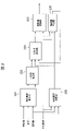
- FIG. 2 is a diagram for explaining the configuration of the target vehicle speed suppression amount calculation unit 109.
- Target vehicle speed suppression amount calculation unit 109 has reference vehicle speed calculation unit 201 , control necessity determination unit 202 , suppression amount calculation unit 203 , suppression amount storage unit 204 , suppression amount conversion unit 205 , and gradual decrease amount calculation unit 206 .
- a reference vehicle speed calculation unit 201 calculates a reference vehicle speed VSP R from the actual vehicle speed, curvature, and deviation amount of the vehicle.
- the reference vehicle speed VSP R is the maximum vehicle speed at which the target trajectory can be passed without deviating.
- Equation (3) shown in FIG. 11 is used as one method of calculating the reference vehicle speed VSPR during turning.
- VSP R reference vehicle speed
- VSP cur actual vehicle speed
- r cur turning radius during running
- r tgt turning radius of the target locus.
- the turning radius r_cur during running is calculated by the equation (4) shown in FIG. 12 using the turning radius r_tgt of the target locus and the deviation amount eY.
- threshold values may be provided for the turning radius rtgt of the target trajectory and the amount of deviation eY, respectively, to prevent the target vehicle speed from being suppressed due to malfunction while the vehicle is traveling on a straight line.
- a dead zone for the deviation amount eY may be provided to prevent the vehicle from being overly sensitive due to vehicle control, thereby preventing the passenger's ride comfort from deteriorating.
- the turning radius r tgt of the target trajectory becomes larger than the turning radius r cur during travel (r tgt >r cur ), and the reference vehicle speed VSP R is greater than the actual vehicle speed VSP cur (VSP R >VSP cur ), there is a possibility that the target vehicle speed will be controlled to increase. Therefore, a limit is set such that the reference vehicle speed VSP R is smaller than the actual vehicle speed VSP cur (VSP R ⁇ VSP cur ), or if the vehicle deviates from the target trajectory on the inner side of the turn, a deviation amount eY is generated. You may take preventive measures such as not doing so.
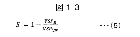
- a suppression amount calculation unit 203 calculates a suppression amount S from the reference vehicle speed VSP R and the target vehicle speed VSP tgt .
- the suppression amount S can be calculated by subtracting from 1 the ratio obtained by dividing the reference vehicle speed VSP R by the target vehicle speed VSP tgt , as shown in equation (5) in FIG.
- a suppression amount calculated using a certain standard according to the deviation speed may be used instead of the suppression amount S described above. In this case, the amount of suppression increases as the deviation speed increases.
- the suppression amount may be calculated based on each of the deviation amount and the deviation speed, and the larger value may be used.
- the control necessity determination unit 202 determines whether or not this control is necessary, that is, whether or not control to suppress the target vehicle speed is necessary based on the target vehicle speed, curvature, and amount of deviation from the target trajectory.
- the curvature c in this embodiment is the curvature of the trajectory of the vehicle during turning, and can be easily converted to an arbitrary turning radius r by equation (6) in FIG.
- the suppression amount holding unit 204 compares the suppression amount S with the suppression amount holding value Sh, and holds a larger value (maximum value). In the case of no control, the holding value Sh is gradually decreased to zero.
- the gradual reduction amount calculation unit 206 calculates the gradual reduction amount by which the holding value Sh is gradually reduced based on the holding value Sh, the target vehicle speed, and the determination of whether or not control is necessary. For example, when the suppression amount S is held as a percentage, when it is desired to restore the suppressed target vehicle speed at an arbitrary acceleration, it is necessary to calculate the gradual decrease amount according to an arbitrary acceleration and target vehicle speed. A gradual decrease calculation unit 206 is provided.
- the suppression amount conversion unit 205 converts the held value into the vehicle speed dimension based on the held value and the target vehicle speed.
- the hold value converted into the vehicle speed dimension by the suppression amount conversion unit 205 is output from the target vehicle speed suppression amount calculation unit 109 to the target vehicle speed subtraction unit 110 .
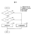
- FIG. 3 is a flow chart showing the processing contents of the control necessity determination unit in FIG.
- the control necessity determination unit 202 executes the determination process shown in the flowchart of FIG. 3, for example, in a predetermined program cycle set in advance.
- the suppression amount is held (S303).
- processing for holding the maximum value of the suppression amount is performed. Specifically, the amount of suppression calculated based on the amount of deviation eY is compared with the value of the amount of suppression that is held, and the larger value is held as the hold value Sh.
- a suppression amount gradual decrease process for gradually decreasing the hold value Sh is performed (S304).
- the deviation amount is determined based on the separation distance. Both may be used to provide inhibitory control if either exceeds the criteria.
- the deviation speed can be calculated, for example, by differentiating the separation distance with respect to time.
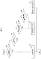
- FIG. 4 is a flowchart showing the content of the suppression amount gradual reduction process shown in S304 of FIG.
- the gradual decrease process is a portion for selecting a gradual decrease speed according to the situation, and the present embodiment is as follows.
- S401 to S404 are cancellation conditions for gradually decreasing the suppression amount to release the suppression control of the target vehicle speed.
- the vehicle is not turning or is about to escape from the turn.
- the vehicle is less likely to deviate or re-deviate. Therefore, it is determined that suppression of the target vehicle speed is not necessary, and processing for gradually decreasing the hold value Sh is performed (S405). That is, when the curvature of the target trajectory is less than a certain value, or when the curvature of the target trajectory gradually decreases as the vehicle travels in the direction of travel, the holding value Sh of the suppression amount is set at the first speed.
- a gradual decrease process is performed. The gradual decrease of the hold value Sh is performed using the gradual decrease amount calculated by the gradual decrease amount calculation unit 206, and the hold value Sh is decreased at a predetermined first speed.
- the process of gradually decreasing the hold value Sh at a second speed slower than that in S405 is performed (S406). That is, when the curvature of the vehicle during turning is constant, or when the target vehicle speed is reduced by a predetermined value or more due to suppression of the target vehicle speed, the hold value of the suppression amount is set at a second speed slower than the first speed. Decrease processing is performed.
- the vehicle is accelerated more slowly than in S405, and the hold value Sh is gradually decreased while ensuring safety by observing the amount of deviation, thereby reducing the sense of discomfort felt by the passenger.
- the second speed of S406 has a lower speed of gradually decreasing the hold value than the first speed of S405, and the second speed of S406 is set to decrease the hold value Sh at a slower rate.
- Departure is suppressed (S407). That is, the curvature of the target trajectory is greater than a certain value (NO in S401), the curvature of the target trajectory has not decreased (NO in S402), and the curvature increases while the vehicle is turning (NO in S403). And, if the target vehicle speed has not decreased by a predetermined value or more due to suppression of the target vehicle speed (NO in S404), processing for continuing suppression of the target vehicle speed using the hold value Sh is performed (S407).
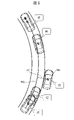
- FIG. 5 is a diagram showing an example in which the vehicle deviates from the target trajectory
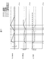
- FIG. 6 is a time chart showing an operation example in this embodiment.
- FIG. 5 and 6 show, as a basic operation of this embodiment, a vehicle 501 given a constant target vehicle speed deviates from the target trajectory 502 due to disturbance during turning, deviates from the target trajectory 502, and deviates from the target locus 502. It shows a case where the target locus 502 is restored by vehicle speed suppression control.
- the vehicle control system causes the vehicle 501 to travel along the target trajectory 502 at the target vehicle speed. Then, when the condition that the turning radius of the target locus is smaller than the turning determination threshold value N is satisfied (YES in S301), the vehicle 501 deviates from the target locus 502 due to disturbances, as indicated by t1 and t2 in FIG. , the traveling position begins to change to the outside of the turn.
- the control necessity determination unit 202 determines that control is necessary, and the determination in S302 shown in the flowchart of FIG. , the process of holding the suppression amount is started.
- the holding unit 204 holds it as a holding value Sh. That is, the reference vehicle speed calculation unit 201 calculates the reference vehicle speed, the suppression amount calculation unit 203 calculates the suppression amount S using the reference vehicle speed and the target vehicle speed, and the suppression amount storage unit 204 holds the suppression amount S as the storage value Sh. be done.
- the vehicle 501 is affected by the disturbance and the deviation eY further increases.
- the hold value Sh of the suppression amount S also increases.
- the target vehicle speed VSP tgt is reduced from the value V before suppression to the value V′ after suppression by subtracting the suppression amount S.
- the vehicle 501 performs control to return to the target trajectory 502.
- the flow chart of FIG. The determination in S302 shown remains YES, and in S303, processing is performed to hold the suppression amount at the hold value Sh.
- the determination in S302 is not NO, and the control amount gradual reduction process in S304 is not performed.
- the suppression amount S calculated by the suppression amount calculation unit 203 decreases according to the deviation amount eY, but the hold value Sh The value (maximum value) of the suppression amount S at t3 is held by the unit 204 . Therefore, the target vehicle speed VSP tgt is also held at the suppressed value V'.
- the process proceeds to S407, where the same control as in the previous period is executed. Therefore, as shown between t4 and t5 in FIG. 6, the hold value Sh continues to be held at the maximum value of the suppression amount S, and the target vehicle speed VSP tgt also continues to be held at the suppressed value V'.
- the target vehicle speed VSP tgt is suppressed and reduced by this control when deviating from the target trajectory 502, so that the vehicle 501 can quickly return to the target trajectory 502 by suppressing the actual vehicle speed and acceleration. becomes.
- target vehicle speed VSP tgt since the amount of suppression of target vehicle speed VSP tgt is held at the maximum hold value Sh, target vehicle speed VSP tgt can be appropriately suppressed, and vehicle 501 can be quickly returned to target trajectory 502 . Even if the vehicle 501 returns to the target trajectory 502, if the predetermined canceling conditions S401 to S404 are not satisfied, the suppression amount continues to be held at the maximum holding value Sh. It can prevent re-deviation after
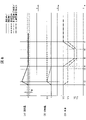
- FIG. 7 is a time chart showing another operation example in this embodiment. As shown in FIG. 6, this time chart shows the case where a vehicle given a constant target vehicle speed deviates from the target trajectory while turning, then temporarily returns to the target trajectory, but deviates again due to the influence of a further disturbance. is assumed.
- the suppression amount calculated by the suppression amount calculation unit 203 increases to S1, and the target vehicle speed is suppressed from V1 to V1'.
- the suppression amount holding unit 204 holds the suppression amount at S1 from t2, and at t3, the deviation amount eY falls within the deviation determination threshold value M, and the vehicle returns to the target trajectory.
- the hold value Sh is gradually decreased from S1 to gradually restore the target vehicle speed.
- the suppression amount S calculated by the suppression amount calculation unit 203 increases in accordance with the increase in the deviation amount eY of the vehicle. It is updated so as to gradually increase, and the target vehicle speed decreases again from V2'. Then, at t7, the deviation amount eY becomes maximum, so S3 of the suppression amount S is held as the holding value Sh.
- the gradual decrease is immediately stopped and the hold of the suppression amount is restarted. If the deviation amount eY further increases and the calculated suppression amount exceeds the previously held value, a larger suppression amount is held to suppress the vehicle from re-departing and reduce the time required for recovery. .
- FIG. 8 is a time chart showing still another operation example in this embodiment.
- the vehicle given a constant target vehicle speed deviates from the target trajectory while turning, and then temporarily returns to the target trajectory. is assumed to change.
- the vehicle From t1 to t2, the vehicle deviates from the target trajectory, the calculated suppression amount S increases to S1, the target vehicle speed is suppressed from V1 to V1′, and at t3, the vehicle deviation eY falls within the deviation determination threshold value M. , and the vehicle returns to the target trajectory.
- the target vehicle speed V decreases from V1 to V2, and the target vehicle speed V' after suppression also decreases from V'1 to V'2. Further, between t6 and t7, the target vehicle speed V increases from V2 to V1, and the target vehicle speed V' after suppression also increases from V'2 to V'1.
- V2 10 km/h at t5
- V'2 7.5 km/h and the vehicle does not stop.
- the automatic driving is terminated at an arbitrary timing, and the subject of driving is handed over to the passenger's manual driving. may be processed.
- the vehicle control system maintains the amount of suppression, continues to suppress the target vehicle speed, informs the passenger that automatic driving will end, and prepares for the passenger to start driving. In that case, the vehicle is immediately switched to manual operation, and the subject of driving is transferred to the passenger.
- the vehicle control system of the present embodiment described above determines whether or not the vehicle 501 is in a deviation state in which the vehicle 501 deviates from the target trajectory 502. to calculate the suppression amount for lowering the target vehicle speed. Then, the maximum value of the suppression amount is held, and the held value is used to suppress the target vehicle speed, and when the vehicle returns to the target trajectory from the deviation state and the preset release condition is satisfied, the suppression amount is satisfied. is decreased at a predetermined rate.
- the amount of suppression for lowering the target vehicle speed is calculated based on the amount of deviation. Then, the target vehicle speed is reduced using the suppression amount to suppress acceleration and vehicle speed of the vehicle. Further, by holding the suppression amount as a ratio to the target vehicle speed, even if the target vehicle speed changes, it is possible to respond without requiring complicated calculations, and it is possible to prevent the target vehicle speed from becoming zero. .
- the target vehicle speed is appropriately reduced and the target trajectory is restored in order to prompt the vehicle 501 to return to the target trajectory 502.
- the target vehicle speed can be kept suppressed appropriately so as not to deviate again later. If the possibility of the vehicle deviating again is low, the target vehicle speed is quickly restored, and when the target vehicle speed changes, excessive acceleration/deceleration and stopping of the vehicle are prevented. can be secured.
Landscapes
- Engineering & Computer Science (AREA)
- Automation & Control Theory (AREA)
- Transportation (AREA)
- Mechanical Engineering (AREA)
- Human Computer Interaction (AREA)
- Control Of Driving Devices And Active Controlling Of Vehicle (AREA)
Abstract
Description
前記車両が前記目標軌跡から逸脱した逸脱状態であるか否かを判定し、
前記逸脱状態であると判定された場合に、前記逸脱状態を示す逸脱量に基づいて目標車速を下げる抑制量を算出し、
前記抑制量の最大値を保持し、該保持した保持値を用いて前記目標車速を抑制し、
前記車両が前記逸脱状態から前記目標軌跡に復帰し、かつ予め設定された解除条件を満たす場合に、前記抑制量の保持値を所定の速さで減少させることを特徴とする。
図1は、本実施形態に係る車両制御システムの概略構成を示す図である。
目標車速抑制量算出部109は、規範車速算出部201、制御要否判断部202、抑制量算出部203、抑制量保持部204、抑制量変換部205、および漸減量算出部206を有する。
本実施例では旋回中の規範車速VSPRの算出方法の一つとして、図11に示す式(3)を用いる。
式(3)において、VSPR:規範車速、VSPcur:実車速、rcur:走行中の旋回半径、rtgt:目標軌跡の旋回半径となる。
このとき、走行中の旋回半径rcurは、目標軌跡の旋回半径rtgtと逸脱量eYを用いて、図12に示す式(4)により算出される。
制御要否判断部202は、例えば予め設定された所定周期のプログラムサイクルで図3のフローチャートに示す判断処理を実行する。
図4は、図3のS304に示す抑制量漸減処理の内容を示したフローチャートである。漸減処理は、状況に応じた漸減速度を選択する部位であり、本実施例としては以下の通りである。S401~S404は、抑制量を漸減させて目標車速の抑制制御を解除する解除条件となる。
本タイムチャートは、図6のように一定の目標車速を与えられた車両が旋回中に目標軌跡から逸脱し、その後に一時的に目標軌跡に復帰したが、さらなる外乱の影響で再度逸脱した場合を想定している。車両が外乱により目標軌跡から逸脱すると、図7のt1からt2に示すように、抑制量算出部203において算出される抑制量がS1まで増加し、目標車速はV1からV1’に抑制される。そして、抑制量保持部204によってt2から抑制量がS1に保持され、t3において逸脱量eYが逸脱判定閾値M内へと収まり、車両が目標軌跡へ復帰する。次に、t4において、図4のS401~S404の解除条件の何れかが満たされると、保持値ShがS1から漸減され、徐々に目標車速を回復させる。
本タイムチャートは、図6のように一定の目標車速を与えられた車両が旋回中に目標軌跡から逸脱し、その後に一時的に目標軌跡に復帰したが、保持値の漸減開始前に目標車速が変化した場合を想定している。
以上のように抑制量を割合で算出し保持することで、目標車速が変化した場合でも複雑な計算を要さず、スムーズな走行が可能となる。
Claims (7)
- 目標車速で目標軌跡に沿って車両を走行させるための制御を行う車両制御装置であって、
前記車両が前記目標軌跡から逸脱した逸脱状態であるか否かを判定し、
前記逸脱状態であると判定された場合に、前記逸脱状態を示す逸脱量に基づいて目標車速を下げる抑制量を算出し、
前記抑制量の最大値を保持し、該保持した保持値を用いて前記目標車速を抑制し、
前記車両が前記逸脱状態から前記目標軌跡に復帰し、かつ予め設定された解除条件を満たす場合に、前記抑制量の保持値を所定の速さで減少させることを特徴とする車両制御装置。 - 前記逸脱量は、前記車両と前記目標軌跡との間の離間距離、または、前記目標軌跡から逸脱する逸脱速度であることを特徴とする請求項1に記載の車両制御装置。
- 前記抑制量は、前記車両の目標車速を低下させる速度量、もしくは、前記目標車速を低下させる割合の少なくとも一方であることを特徴とする請求項1に記載の車両制御装置。
- 前記抑制量の保持値を所定の速さで減少させている途中で、前記車両が再び前記逸脱状態であると判定された場合に、前記抑制量の保持値の漸減を停止し、前記抑制量の最大値の保持と、前記保持値を用いた前記目標車速の抑制を行うことを特徴とする請求項1に記載の車両制御装置。
- 前記目標軌跡の曲率が一定値以下、もしくは、前記目標軌跡の曲率が前記車両の進行方向に移行するにしたがって漸次減少している場合には、前記抑制量の保持値を第1の速さで減少させ、
前記目標軌跡の曲率が一定値よりも大きく、かつ前記目標軌跡の曲率が前記車両の進行方向に移行するにしたがって漸次減少していない場合であって、前記車両の旋回中の曲率が一定、もしくは、前記目標車速の抑制により前記目標車速が所定値以上低下しているときは、前記抑制量の保持値を前記第1の速さよりも遅い第2の速さで減少させることを特徴とする請求項1に記載の車両制御装置。 - 前記目標軌跡の曲率が一定値よりも大きく、かつ前記目標軌跡の曲率が減少しておらず、かつ前記車両の旋回中の曲率が増加し、かつ前記目標車速の抑制により前記目標車速が所定値以上低下していない場合に、前記保持値を用いた前記目標車速の抑制を継続することを特徴とする請求項5に記載の車両制御装置。
- 前記車両の前記目標軌跡からの逸脱により前記保持値を用いて前記目標車速を抑制した後に、前記車両の運転を自動運転から手動運転へと切り替えるハンドオーバー処理を行うことを特徴とする請求項1に記載の車両制御装置。
Priority Applications (2)
| Application Number | Priority Date | Filing Date | Title |
|---|---|---|---|
| DE112022001116.5T DE112022001116T5 (de) | 2021-05-13 | 2022-02-28 | Fahrzeugsteuervorrichtung |
| US18/553,619 US12576840B2 (en) | 2021-05-13 | 2022-02-28 | Vehicle control device |
Applications Claiming Priority (2)
| Application Number | Priority Date | Filing Date | Title |
|---|---|---|---|
| JP2021081505A JP7606408B2 (ja) | 2021-05-13 | 2021-05-13 | 車両制御装置 |
| JP2021-081505 | 2021-05-13 |
Publications (1)
| Publication Number | Publication Date |
|---|---|
| WO2022239388A1 true WO2022239388A1 (ja) | 2022-11-17 |
Family
ID=84029125
Family Applications (1)
| Application Number | Title | Priority Date | Filing Date |
|---|---|---|---|
| PCT/JP2022/008419 Ceased WO2022239388A1 (ja) | 2021-05-13 | 2022-02-28 | 車両制御装置 |
Country Status (4)
| Country | Link |
|---|---|
| US (1) | US12576840B2 (ja) |
| JP (1) | JP7606408B2 (ja) |
| DE (1) | DE112022001116T5 (ja) |
| WO (1) | WO2022239388A1 (ja) |
Families Citing this family (2)
| Publication number | Priority date | Publication date | Assignee | Title |
|---|---|---|---|---|
| JP7871795B2 (ja) * | 2023-12-13 | 2026-06-09 | トヨタ自動車株式会社 | 車両制御装置 |
| US20260124912A1 (en) * | 2024-11-01 | 2026-05-07 | Deere & Company | Speed control system for an agricultural machine |
Citations (4)
| Publication number | Priority date | Publication date | Assignee | Title |
|---|---|---|---|---|
| JP2004284484A (ja) * | 2003-03-20 | 2004-10-14 | Nissan Motor Co Ltd | 車線逸脱防止装置 |
| JP2007008332A (ja) * | 2005-06-30 | 2007-01-18 | Nissan Motor Co Ltd | 車両用走行制御装置 |
| JP2008050001A (ja) * | 2007-10-05 | 2008-03-06 | Nissan Motor Co Ltd | 減速制御装置 |
| JP2018158641A (ja) * | 2017-03-22 | 2018-10-11 | いすゞ自動車株式会社 | 走行制御装置、車両および走行制御方法 |
Family Cites Families (8)
| Publication number | Priority date | Publication date | Assignee | Title |
|---|---|---|---|---|
| JP3783562B2 (ja) * | 2000-12-28 | 2006-06-07 | 日産自動車株式会社 | 車両の走行制御装置 |
| JP2003327011A (ja) | 2002-05-10 | 2003-11-19 | Mitsubishi Electric Corp | 車両用走行制御装置 |
| JP3987044B2 (ja) * | 2004-02-19 | 2007-10-03 | 本田技研工業株式会社 | 車間距離制御装置 |
| US7881848B2 (en) * | 2006-04-28 | 2011-02-01 | Nissan Motor Co., Ltd. | Lane departure prevention apparatus and method |
| JP6731234B2 (ja) * | 2015-10-30 | 2020-07-29 | 日立オートモティブシステムズ株式会社 | 車両運動制御装置及びその方法 |
| JP6728558B2 (ja) * | 2016-01-25 | 2020-07-22 | 日立オートモティブシステムズ株式会社 | 自動運転制御装置および自動運転制御方法 |
| JP6970807B2 (ja) * | 2018-03-16 | 2021-11-24 | 株式会社日立製作所 | 移動体制御装置 |
| US20230202558A1 (en) * | 2020-06-12 | 2023-06-29 | Mitsubishi Electric Corporation | Automatic steering control device and automatic steering control system for vehicle |
-
2021
- 2021-05-13 JP JP2021081505A patent/JP7606408B2/ja active Active
-
2022
- 2022-02-28 US US18/553,619 patent/US12576840B2/en active Active
- 2022-02-28 DE DE112022001116.5T patent/DE112022001116T5/de active Pending
- 2022-02-28 WO PCT/JP2022/008419 patent/WO2022239388A1/ja not_active Ceased
Patent Citations (4)
| Publication number | Priority date | Publication date | Assignee | Title |
|---|---|---|---|---|
| JP2004284484A (ja) * | 2003-03-20 | 2004-10-14 | Nissan Motor Co Ltd | 車線逸脱防止装置 |
| JP2007008332A (ja) * | 2005-06-30 | 2007-01-18 | Nissan Motor Co Ltd | 車両用走行制御装置 |
| JP2008050001A (ja) * | 2007-10-05 | 2008-03-06 | Nissan Motor Co Ltd | 減速制御装置 |
| JP2018158641A (ja) * | 2017-03-22 | 2018-10-11 | いすゞ自動車株式会社 | 走行制御装置、車両および走行制御方法 |
Also Published As
| Publication number | Publication date |
|---|---|
| US20240182029A1 (en) | 2024-06-06 |
| JP2022175257A (ja) | 2022-11-25 |
| JP7606408B2 (ja) | 2024-12-25 |
| DE112022001116T5 (de) | 2023-12-21 |
| US12576840B2 (en) | 2026-03-17 |
Similar Documents
| Publication | Publication Date | Title |
|---|---|---|
| JP5353211B2 (ja) | 走行制御装置 | |
| JP5780996B2 (ja) | 車両走行制御装置 | |
| JP4354998B2 (ja) | 自動車の間隔制御システム | |
| US11383698B2 (en) | Device and method for controlling vehicle movement, and device and method for generating target course | |
| EP2853457B1 (en) | Method and apparatus for performing driving assistance | |
| JP4497231B2 (ja) | 車両用速度制御装置 | |
| JP3167987B2 (ja) | カーブ進入制御装置 | |
| JP2013248925A (ja) | 車両制御装置 | |
| EP4045370A1 (en) | Adaptive cruise control | |
| JP2009061878A (ja) | 走行制御装置 | |
| JPWO2017077807A1 (ja) | 車両走行制御装置 | |
| US12371018B2 (en) | Driver assistance method with virtual target for adaptive cruise control | |
| WO2014119171A1 (ja) | 車両の走行制御装置 | |
| JP5762647B2 (ja) | 後輪軸操舵システムを有する自動車用の装置および自動車の制御方法 | |
| JP2018052427A (ja) | 車両制御装置 | |
| JP7606408B2 (ja) | 車両制御装置 | |
| JP2018203126A (ja) | 車両運動制御装置 | |
| US10286910B2 (en) | Vehicle running control apparatus | |
| JP3987044B2 (ja) | 車間距離制御装置 | |
| JP7637253B2 (ja) | 車両制御装置、車両制御方法、及び車両制御システム | |
| KR102562411B1 (ko) | 전방에 위치한 커브를 통과할 시 자기차량의 차량운전자를 지원하기 위한 방법 | |
| JP6313834B2 (ja) | 車両制御装置 | |
| JP2008068752A (ja) | 車両の走行制御装置 | |
| JP2003312309A (ja) | 車両用走行制御装置 | |
| JP2007331580A (ja) | 車両速度制御システム |
Legal Events
| Date | Code | Title | Description |
|---|---|---|---|
| 121 | Ep: the epo has been informed by wipo that ep was designated in this application |
Ref document number: 22807095 Country of ref document: EP Kind code of ref document: A1 |
|
| WWE | Wipo information: entry into national phase |
Ref document number: 18553619 Country of ref document: US |
|
| WWE | Wipo information: entry into national phase |
Ref document number: 112022001116 Country of ref document: DE |
|
| 122 | Ep: pct application non-entry in european phase |
Ref document number: 22807095 Country of ref document: EP Kind code of ref document: A1 |
|
| WWG | Wipo information: grant in national office |
Ref document number: 18553619 Country of ref document: US |