WO2022239136A1 - ネットワーク管理装置、ネットワーク管理方法およびプログラム - Google Patents
ネットワーク管理装置、ネットワーク管理方法およびプログラム Download PDFInfo
- Publication number
- WO2022239136A1 WO2022239136A1 PCT/JP2021/017977 JP2021017977W WO2022239136A1 WO 2022239136 A1 WO2022239136 A1 WO 2022239136A1 JP 2021017977 W JP2021017977 W JP 2021017977W WO 2022239136 A1 WO2022239136 A1 WO 2022239136A1
- Authority
- WO
- WIPO (PCT)
- Prior art keywords
- path
- route
- redundant
- node
- nodes
- Prior art date
Links
- 238000007726 management method Methods 0.000 title claims description 54
- 238000004891 communication Methods 0.000 claims abstract description 86
- 238000000605 extraction Methods 0.000 claims abstract description 16
- 239000000284 extract Substances 0.000 claims abstract description 15
- 238000004364 calculation method Methods 0.000 claims abstract description 13
- 230000006866 deterioration Effects 0.000 claims abstract description 7
- 238000000034 method Methods 0.000 description 11
- 238000010586 diagram Methods 0.000 description 10
- 230000005540 biological transmission Effects 0.000 description 6
- 230000006870 function Effects 0.000 description 6
- 238000012706 support-vector machine Methods 0.000 description 6
- 230000015654 memory Effects 0.000 description 5
- 238000005516 engineering process Methods 0.000 description 2
- 239000000203 mixture Substances 0.000 description 2
- 235000008694 Humulus lupulus Nutrition 0.000 description 1
- 238000010276 construction Methods 0.000 description 1
- 230000001186 cumulative effect Effects 0.000 description 1
- 230000000694 effects Effects 0.000 description 1
- 230000003287 optical effect Effects 0.000 description 1
- 238000004549 pulsed laser deposition Methods 0.000 description 1
- 239000004065 semiconductor Substances 0.000 description 1
- 238000004904 shortening Methods 0.000 description 1
Images


Classifications
-
- H—ELECTRICITY
- H04—ELECTRIC COMMUNICATION TECHNIQUE
- H04L—TRANSMISSION OF DIGITAL INFORMATION, e.g. TELEGRAPHIC COMMUNICATION
- H04L41/00—Arrangements for maintenance, administration or management of data switching networks, e.g. of packet switching networks
- H04L41/14—Network analysis or design
- H04L41/142—Network analysis or design using statistical or mathematical methods
-
- H—ELECTRICITY
- H04—ELECTRIC COMMUNICATION TECHNIQUE
- H04L—TRANSMISSION OF DIGITAL INFORMATION, e.g. TELEGRAPHIC COMMUNICATION
- H04L41/00—Arrangements for maintenance, administration or management of data switching networks, e.g. of packet switching networks
- H04L41/06—Management of faults, events, alarms or notifications
- H04L41/0654—Management of faults, events, alarms or notifications using network fault recovery
- H04L41/0663—Performing the actions predefined by failover planning, e.g. switching to standby network elements
Definitions
- the present invention relates to a network management device, network management method and program.
- Non-Patent Document 1 discloses a technology for calculating redundant paths for improving network reliability.
- the main route and the redundant route are two routes that share the same transmission node and reception node and do not have a common relay node. Of the two paths, the one with the shorter path length is the primary path, and the one with the longer path length is the redundant path.
- the main route and the redundant route have overlapping relay nodes, if a failure occurs in the relay node, both the main route and the redundant route become unusable. It is possible to increase the reliability of the redundant path against failure of the main path.
- the path length difference between the main path and the redundant path may increase depending on the combination of the transmission node and the reception node.
- the communication network is not a complete graph and has limited edges to choose from. If the path length difference is large, the communication performance will deteriorate when the communication path is switched from the main path to the redundant path. Therefore, it is desirable to identify combinations of sending nodes and receiving nodes where communication performance is relatively degraded due to the path length difference between the primary path and the redundant path, and modify the network so that an appropriate redundant path can be configured.
- One aspect of the present invention is a network management device that manages a communication network having a plurality of nodes and a plurality of edges that connect the nodes, the network management device comprising: For each node pair that is a pair, a main path and a redundant path that are configured by the plurality of edges and connect between the node pairs, the relay node on the main path and the relay node on the redundant path a route identifying unit that identifies the primary route and the redundant route that do not overlap, a route length difference calculator that calculates a route length difference between the primary route and the redundant route for each of the node pairs, and the route length difference and an extracting unit for extracting an outlier pair that causes deterioration in communication performance when switching from the primary path to the redundant path from the node pair based on the above.
- One aspect of the present invention is the network management device described above, wherein an edge not included in the communication network is added to the communication network, and the edge is added to the communication network so that the edge pair is changed from the primary path to the redundant path an additional edge identifying unit that identifies an additional edge that suppresses a decrease in communication performance when switching to the communication network; , and the additional edge identifying unit identifies the main path and the redundant path for each of the outlier pairs in the case of adding to The smaller ones are identified as the additional edges.
- the extraction unit extracts the outlier pair by statistical processing based on a combination of the path length difference and the distance between the node pairs.
- One aspect of the present invention is a network management method for managing a communication network having a plurality of nodes and a plurality of edges connecting the nodes, the network management method comprising: For each node pair that is a pair, a main path and a redundant path that are configured by the plurality of edges and connect between the node pairs, the relay node on the main path and the relay node on the redundant path identifying a main route and a redundant route that do not overlap; obtaining a route length difference between the main route and the redundant route for each of the node pairs; and extracting an outlier pair that causes deterioration in communication performance when switching from the primary path to the redundant path.
- a program in which a computer that manages a communication network having a plurality of nodes and a plurality of edges that connect between the nodes is given to a computer for each node pair that is a pair of nodes on the communication network.
- a main route and a redundant route configured by the plurality of edges and connecting between the node pairs, wherein the relay node on the main route and the relay node on the redundant route do not overlap; and identifying the redundant system path; obtaining a path length difference between the primary path and the redundant path for each of the node pairs; and determining the primary path among the node pairs based on the path length difference a step of extracting an outlier pair that causes a decrease in communication performance when switching from the redundant system path to the redundant system path.
- a communication network it is possible to identify a pair of nodes in which the communication performance is degraded when switching from the primary path to the redundant path.
- FIG. 3 is a diagram showing an example of a main path and redundant paths according to the first embodiment
- 1 is a schematic block diagram showing the configuration of a network management device according to a first embodiment
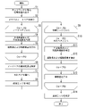
- FIG. 4 is a flow chart showing the operation of the network management device according to the first embodiment
- FIG. 2 is a diagram illustrating an example of distribution of path length differences of node pairs in a communication network
- FIG. 8 is a diagram showing an example of the distribution of path length differences of node pairs when additional edges are determined by the method according to the first embodiment
- 1 is a schematic block diagram showing a configuration of a computer according to at least one embodiment
- FIG. 1 is a diagram showing an example of a main route Rp and a redundant route Rs according to the first embodiment.
- a communication network is composed of a plurality of nodes N and edges E connecting the nodes N.
- the nodes of the communication network according to the first embodiment normally communicate via the primary route Rp, and when a failure occurs in the primary route Rp, switch to the redundant route Rs for communication.
- the main route Rp and the redundant route Rs do not have relay nodes in common.
- a relay node is a node excluding a transmission node and a reception node among nodes constituting a route. Of the two paths, the one with the shorter path length is the primary path Rp, and the one with the longer path length is the redundant path Rs.
- the communication network shown in FIG. 1 includes six nodes N, node N1 to node N7.
- the shortest path when the transmission node is N1 and the reception node is N7 is the path connecting N1, N2, N3, and N7 in this order.
- this shortest route cannot constitute a redundant route Rs that does not have a common relay node, it is not adopted as the primary route Rp.
- the route connecting N1, N4, N3 and N7 in this order is the primary route Rp
- the route connecting N1, N2, N6, N5 and N7 in this order is the redundant route Rs.
- the network management device 1 determines appropriate additional edges so as to improve the quality of multiple routes with low communication performance. In other words, the network management device 1 identifies the minimum additional edges that improve the communication performance of the entire communication network.
- FIG. 2 is a schematic block diagram showing the configuration of the network management device 1 according to the first embodiment.
- the network management device 1 includes a request reception unit 11, a network database 12, a node pair identification unit 13, a route identification unit 14, a path length difference calculation unit 15, an extraction unit 16, a candidate edge identification unit 17, an index value calculation unit 18, an additional edge A determination unit 19 is provided.
- the request receiving unit 11 receives requests for improving the communication network.
- the improvement request contains the ID of the communication network to be improved.
- the network management device 1 starts the additional edge determination process with the reception of the improvement request as a trigger.
- the network database 12 stores, for each communication network, information related to the nodes and edges that make up the communication network. For example, network database 12 stores the latitude and longitude of each node, the start node, end node and length of each edge. The network database 12 also stores information on edges that should not be added (prohibited edges) for each communication network. Examples of prohibited edges include edges that are expensive to add, such as edges that connect nodes across a mountain range.
- the node pair identifying unit 13 Based on the information stored in the network database 12, the node pair identifying unit 13 identifies all combinations of transmitting nodes and receiving nodes (node pairs) from a plurality of nodes that make up the communication network.
- the route identification unit 14 identifies the main route Rp and the redundant route Rs connecting the node pairs identified by the node pair identification unit 13 . As shown in FIG. 1, the main route Rp and the redundant route Rs are two routes having the same transmission node and reception node and no common relay node. The route identifying unit 14 identifies the main route Rp and the redundant route Rs such that, for example, the sum of the route lengths of the main route Rp and the redundant route Rs is minimized. The route identifying unit 14 can identify the main route Rp and the redundant route Rs by the technique described in Non-Patent Document 1, for example.
- the path length difference calculation unit 15 calculates the path lengths of the main path Rp and the redundant path Rs identified by the path identification unit 14, and the path length difference between the main path Rp and the redundant path Rs.
- the path length may be obtained, for example, by summing the lengths associated with the edges forming the route, or by summing the distances between the relay nodes forming the route.
- the distance between nodes can be obtained from the latitude and longitude of the nodes.
- the extraction unit 16 extracts outlier pairs, which are node pairs with relatively large path length differences, based on the path lengths and path length differences calculated by the path length difference calculation unit 15 .
- the extraction unit 16 extracts outlier pairs according to the following procedure. First, the extraction unit 16 sets the sum of path lengths and the path length difference as attributes of a plurality of node pairs. Next, the extraction unit 16 generates an identification boundary for identifying normal classes using a one-class SVM (Support Vector Machine). At this time, the extraction unit 16 extracts node pairs closer to the origin than the set identification boundaries as outlier pairs.
- the extraction unit 16 according to another embodiment may extract outlier pairs by a technique other than SVM.
- the extraction unit 16 may learn a Gaussian mixture model representing the distribution of path length differences based on node pairs, and extract outlier pairs by comparison with the Gaussian mixture model.
- the candidate edge identification unit 17 Based on the information stored in the network database 12, the candidate edge identification unit 17 identifies a plurality of candidate edges that are candidates for edges to be added to the communication network.
- the candidate edge identification unit 17 identifies, as a candidate edge group, edges that form a complete graph of a group of nodes that form the communication network, excluding edges that already exist in the communication network and forbidden edges.
- the index value calculation unit 18 calculates an index value indicating the degree of deterioration in communication performance when switching from the main route Rp to the redundant route Rs for the plurality of out pairs extracted by the extraction unit 16 .
- the index value serves as an index for optimizing communication performance.
- the index value is obtained by the root mean square of the path length differences of the plurality of outlier pairs extracted by the extraction unit 16 .
- the additional edge determination unit 19 identifies the edge with the smallest index value as an additional edge.
- FIG. 3 is a flow chart showing the operation of the network management device 1 according to the first embodiment.
- An administrator of a communication network transmits an improvement request to the network management device 1 when he/she wants to consider improving the performance of a certain communication network.
- the node pair identification unit 13 reads out information related to the network to be improved from the network database 12 based on the communication network ID included in the improvement request. (Step S1).
- the node pair identification unit 13 identifies all combinations (node pairs) of transmission nodes and reception nodes from all nodes constituting the network (step S2).
- the network management device 1 selects each of the identified node pairs one by one (step S3), and performs the following calculations in steps S4 and S5 for the selected node pairs.
- the route identifying unit 14 identifies the main route Rp and the redundant route Rs connecting the transmitting node and the receiving node for the node pair selected in step S3 (step S4).
- the path length difference calculator 15 calculates the path lengths of the main path Rp and the redundant path Rs identified in step S4, and the path length difference between the main path Rp and the redundant path Rs (step S5).
- the extraction unit 16 uses the sum of the path lengths and the path length difference as attributes to identify an identification boundary that identifies a normal class using the one-class SVM (step S6).
- the extraction unit 16 extracts, from among the node pairs specified in step S2, those closer to the origin than the set identification boundary as outlier pairs (step S7).
- the candidate edge identification unit 17 Based on the information stored in the network database 12, the candidate edge identification unit 17 identifies a plurality of candidate edges that are candidates for edges to be added to the communication network (step S8).
- the network management device 1 selects one by one from the plurality of candidate edges identified in step S8 (step S9), and performs the following calculations in steps S10 to S13 for each candidate edge.
- the network management device 1 selects each of the plurality of outlier pairs extracted in step S7 (step S10), and performs the following calculations in steps S11 and S12 for each outlier pair.
- the route identifying unit 14 determines the main route Rp and the redundant route Rs connecting the disjoint pairs selected in step S10 for the candidate network obtained by adding the candidate edge selected in step S9 to the communication network read out in step S1. is specified (step S11).
- the path length difference calculator 15 calculates the path lengths of the main path Rp and the redundant path Rs identified in step S11 and the path length difference between the main path Rp and the redundant path Rs (step S12).
- the index value calculator 18 calculates the root mean square of the path length differences of the plurality of outlier pairs calculated in step S12 as an index value (step S13). .
- the additional edge determination unit 19 identifies the edge with the smallest index value calculated in step S13 as an additional edge (step S14).
- the additional edge determining unit 19 displays the specified additional edge on a terminal operated by the administrator of the communication network.
- the additional edge determining unit 19 may display the distribution of the path length difference of the current communication network and the distribution of the path length difference of the communication network when the additional edge is added so that they can be compared.
- the additional edge determination unit 19 may indicate the degree of improvement by superimposing the graph in FIG. 4 and the graph in FIG. 5 to be described later.
- FIG. 4 is a diagram showing an example of distribution of path length differences of node pairs in a communication network.
- FIG. 4 is a graph in which the horizontal axis represents the path length difference between node pairs, and the vertical axis represents the frequency of the path length difference and the cumulative relative frequency.
- the path length difference has a distribution close to the logarithmic normal distribution.
- node pairs with long path length differences are scattered. According to the network management device 1 according to the first embodiment, such node pairs are extracted as outlier pairs. From the example shown in FIG.
- the network management device 1 determines an additional edge such that the root mean square of the path length difference of such an outlier pair becomes small, thereby reducing the path length difference according to the distribution of the outlier pair.
- the communication network can be modified to have
- FIG. 5 is a diagram showing an example of distribution of path length differences of node pairs when additional edges are determined by the method according to the first embodiment.
- the network management device 1 can reduce the amount of calculation involved in the additional edge determination processing by limiting the calculation of the main route Rp and the redundant route Rs when adding a candidate edge to only the outlier pair.
- the network management device 1 can positively determine additional edges so that there are no outlier pairs by limiting the calculation target of the index value to outlier pairs. If the index value is obtained based on all node pairs, there is a possibility that the path length difference of outlier pairs is not improved and additional edges are obtained that reduce the path length difference of already distributed node pairs.
- the network management device 1 extracts outlier pairs based on the path length difference between the main path Rp and the redundant path Rs for each node pair on the communication network. As a result, the network management device 1 can identify communication between nodes in the communication network in which deterioration in communication performance occurs. In other words, the network management device 1 can identify a pair of nodes in which the communication performance is degraded when switching from the primary route Rp to the redundant route Rs.
- the network management device 1 identifies, for each of a plurality of candidate edges, the main route Rp and the redundant route Rs for each outlier pair when the candidate edge is added to the communication network. , the candidate edge with the smallest index value related to the path length difference of the outlier pair is specified as the additional edge. Additional edges identified by this method are edges that contribute significantly to shortening the path length difference of outlier pairs. As a result, the network management device 1 can positively determine additional edges so that there are no disconnected pairs.
- the network management device 1 extracts outlier pairs by SVM using a combination of the path length difference and the sum of the path lengths as elements.
- the sum of the path lengths of the main path Rp and the redundant path Rs is a value corresponding to the distance between the node pairs.
- the path length difference between the main path Rp and the redundant path Rs varies depending on the distance between the node pairs.
- the redundant route Rs has a constraint that it does not include the same relay node as the primary route Rp connecting the node pair by the shortest route. Therefore, the longer the distance between the node pairs, the longer the length of the redundant route Rs. Therefore, by obtaining an outlier using a combination of the path length difference and the sum of the path lengths as an element, it is possible to prevent a path length difference that increases due to the distance between node pairs from becoming an outlier.
- the network management device 1 may be composed of a single computer, or the configuration of the network management device 1 may be divided into a plurality of computers, and the plurality of computers may cooperate with each other. It may function as the network management device 1 by doing so.
- the network management device 1 identifies a plurality of outlier pairs, which are node pairs with low communication performance, and determines appropriate additional edges so as to improve the quality of the plurality of outlier pairs. Not limited.
- the network management device 1 according to another embodiment may extract and present outlier pairs in the communication network, but may not determine additional edges.
- the network management device 1 extracts outlier pairs by performing statistical processing such as SVM using the sum of the path lengths of the primary path Rp and the redundant path Rs as an element, but is not limited to this. .
- statistical processing such as SVM
- other values according to the distance between node pairs such as the number of hops between node pairs and the linear distance between nodes, may be used as factors.
- the network management device 1 according to another embodiment may extract outlier pairs based only on the path length without using the value corresponding to the distance between the node pairs.
- the network management device 1 stores information related to the network configuration in the network database 12 in advance, it is not limited to this.
- the network management device 1 according to another embodiment does not need to include the network database 12 when receiving an improvement request including data related to a communication network to be improved.
- FIG. 6 is a schematic block diagram showing the configuration of a computer according to at least one embodiment.
- Computer 90 comprises processor 91 , main memory 93 , storage 95 and interface 97 .
- the network management device 1 described above is implemented in a computer 90 .
- the operation of each processing unit described above is stored in the storage 95 in the form of a program.
- the processor 91 reads out a program from the storage 95, develops it in the main memory 93, and executes the above processes according to the program.
- the processor 91 secures storage areas corresponding to the storage units described above in the main memory 93 according to the program. Examples of the processor 91 include a CPU (Central Processing Unit), a GPU (Graphic Processing Unit), a microprocessor, and the like.
- the program may be for realizing part of the functions to be exhibited by the computer 90.
- the program may function in combination with another program already stored in the storage or in combination with another program installed in another device.
- the computer 90 may include a custom LSI (Large Scale Integrated Circuit) such as a PLD (Programmable Logic Device) in addition to or instead of the above configuration.
- PLDs include PAL (Programmable Array Logic), GAL (Generic Array Logic), CPLD (Complex Programmable Logic Device), and FPGA (Field Programmable Gate Array).
- part or all of the functions implemented by processor 91 may be implemented by the integrated circuit.
- Such an integrated circuit is also included as an example of a processor.
- Examples of the storage 95 include magnetic disks, magneto-optical disks, optical disks, and semiconductor memories.
- the storage 95 may be an internal medium directly connected to the bus of the computer 90, or an external medium connected to the computer 90 via an interface 97 or communication line. Further, when this program is delivered to the computer 90 via a communication line, the computer 90 receiving the delivery may load the program into the main memory 93 and execute the above process.
- storage 95 is a non-transitory, tangible storage medium.
- the program may be for realizing part of the functions described above.
- the program may be a so-called difference file (difference program) that implements the above-described functions in combination with another program already stored in the storage 95 .
- Network management device 11 Request receiving unit 12
- Network database 13
- Node pair specifying unit 14
- Path specifying unit 15
- Path length difference calculating unit 16
- Extracting unit 17
- Candidate edge specifying unit 18
- Index value calculating unit 19
- Addition Edge determination unit E
Landscapes
- Physics & Mathematics (AREA)
- Algebra (AREA)
- General Physics & Mathematics (AREA)
- Mathematical Analysis (AREA)
- Mathematical Optimization (AREA)
- Mathematical Physics (AREA)
- Probability & Statistics with Applications (AREA)
- Pure & Applied Mathematics (AREA)
- Engineering & Computer Science (AREA)
- Computer Networks & Wireless Communication (AREA)
- Signal Processing (AREA)
- Data Exchanges In Wide-Area Networks (AREA)
Abstract
経路特定部は、通信ネットワーク上のノードのペアであるノードペアそれぞれについて、主系経路および冗長系経路を特定する。主系路および冗長系経路は、複数のエッジで構成され、主系経路上のノードと冗長系経路上のノードが重複しない経路である。経路長差算出部は、ノードペアそれぞれについて主系経路と冗長系経路との経路長差を求める。抽出部は、経路長差に基づいて、ノードペアのうち主系経路から冗長系経路に切り替えたときに通信性能の低下が生じる外れペアを抽出する。
Description
本発明は、ネットワーク管理装置、ネットワーク管理方法およびプログラムに関する。
非特許文献1には、ネットワークの信頼性を向上させるための冗長系経路の算出技術が開示されている。非特許文献1によれば、主系経路と冗長系経路は、送信ノード及び受信ノードを同じくし、共通する中継ノードを有しない2つの経路である。2つの経路のうち経路長が短いものが主系経路であり、経路長が長いものが冗長系経路である。主系経路と冗長系経路とで重複する中継ノードを有する場合、当該中継ノードに障害が発生すると主系経路および冗長系経路の両方が使用できなくなるところ、重複する中継ノードを備えないことで、主系経路の障害に対する冗長系経路の信頼性を高めることができる。
R. Bhandari, "Optimal Physical Diversity Algorithms and Survivable Networks", IEEE Conference Paper, pp. 433-441
非特許文献1に記載の技術を通信ネットワークに適用する場合、送信ノードと受信ノードの組み合わせによっては、主系経路と冗長系経路の経路長差が大きくなることがある。この理由の一つとして、通信ネットワークが完全グラフではなく、選択可能なエッジが限られることが挙げられる。経路長差が大きいと、通信経路を主系経路から冗長系経路に切り替えたときに通信性能の低下が生じる。そのため、主系経路と冗長系経路の経路長差による通信性能の低下が相対的に大きい送信ノードと受信ノードの組み合わせを特定し、適切な冗長系経路を構成できるようネットワークを変更することが望まれる。
本発明の目的は、通信ネットワークにおいて、主系経路から冗長系経路に切り替えたときに通信性能の低下が生じる送信ノードと受信ノードのペアを特定することができるネットワーク管理装置、ネットワーク管理方法およびプログラムを提供することにある。
本発明の一態様は、ネットワーク管理装置であって、複数のノードと、前記ノード間を接続する複数のエッジとを有する通信ネットワークを管理するネットワーク管理装置であって、前記通信ネットワーク上のノードのペアであるノードペアそれぞれについて、前記複数のエッジで構成され、当該ノードペア間を接続する主系経路および冗長系経路であって、前記主系経路上の中継ノードと前記冗長系経路上の中継ノードが重複しない前記主系経路および前記冗長系経路を特定する経路特定部と、前記ノードペアそれぞれについて前記主系経路と前記冗長系経路との経路長差を求める経路長差算出部と、前記経路長差に基づいて、前記ノードペアのうち前記主系経路から前記冗長系経路に切り替えたときに通信性能の低下が生じる外れペアを抽出する抽出部とを備える。
本発明の一態様は、上記のネットワーク管理装置であって、前記通信ネットワークに含まれないエッジであって、前記通信ネットワークに追加することで、前記外れペアにおいて前記主系経路から前記冗長系経路に切り替えたときの通信性能の低下を抑制する追加エッジを特定する追加エッジ特定部を備え、前記経路特定部は、前記追加エッジの候補である複数の候補エッジについて、前記候補エッジを前記通信ネットワークに加えた場合における前記外れペアそれぞれに係る主系経路および冗長系経路を特定し、前記追加エッジ特定部は、前記複数の候補エッジのうち、前記外れペアの経路長差に係る指標値が最も小さくなるものを、前記追加エッジとして特定する。
本発明の一態様は、上記のネットワーク管理装置において、前記抽出部は、前記経路長差と、前記ノードペア間の距離との組み合わせに基づく統計処理によって、前記外れペアを抽出する。
本発明の一態様は、ネットワーク管理方法であって、複数のノードと、前記ノード間を接続する複数のエッジとを有する通信ネットワークを管理するネットワーク管理方法であって、前記通信ネットワーク上のノードのペアであるノードペアそれぞれについて、前記複数のエッジで構成され、当該ノードペア間を接続する主系経路および冗長系経路であって、前記主系経路上の中継ノードと前記冗長系経路上の中継ノードが重複しない主系経路および冗長系経路を特定するステップと、前記ノードペアそれぞれについて前記主系経路と前記冗長系経路との経路長差を求めるステップと、前記経路長差に基づいて、前記ノードペアのうち前記主系経路から前記冗長系経路に切り替えたときに通信性能の低下が生じる外れペアを抽出するステップとを有する。
本発明の一態様は、プログラムであって、複数のノードと、前記ノード間を接続する複数のエッジとを有する通信ネットワークを管理するコンピュータに、前記通信ネットワーク上のノードのペアであるノードペアそれぞれについて、前記複数のエッジで構成され、当該ノードペア間を接続する主系経路および冗長系経路であって、前記主系経路上の中継ノードと前記冗長系経路上の中継ノードが重複しない前記主系経路および前記冗長系経路を特定するステップと、前記ノードペアそれぞれについて前記主系経路と前記冗長系経路との経路長差を求めるステップと、前記経路長差に基づいて、前記ノードペアのうち前記主系経路から前記冗長系経路に切り替えたときに通信性能の低下が生じる外れペアを抽出するステップとを実行させる。
上記少なくとも1つの態様によれば、通信ネットワークにおいて、主系経路から冗長系経路に切り替えたときに通信性能の低下が生じるノードのペアを特定することができる。
〈第1の実施形態〉
以下、図面を参照しながら実施形態について詳しく説明する。
第1の実施形態に係るネットワーク管理装置1は、通信ネットワークを管理する。
図1は、第1の実施形態に係る主系経路Rpと冗長系経路Rsの例を示す図である。通信ネットワークは、複数のノードNと、ノードN間を接続するエッジEによって構成される。第1の実施形態に係る通信ネットワークのノード同士は、平常時に主系経路Rpを介して通信を行い、主系経路Rpに障害が発生したときに冗長系経路Rsに切り替えて通信を行う。
以下、図面を参照しながら実施形態について詳しく説明する。
第1の実施形態に係るネットワーク管理装置1は、通信ネットワークを管理する。
図1は、第1の実施形態に係る主系経路Rpと冗長系経路Rsの例を示す図である。通信ネットワークは、複数のノードNと、ノードN間を接続するエッジEによって構成される。第1の実施形態に係る通信ネットワークのノード同士は、平常時に主系経路Rpを介して通信を行い、主系経路Rpに障害が発生したときに冗長系経路Rsに切り替えて通信を行う。
主系経路Rpと冗長系経路Rsは、互いに共通する中継ノードを有しない。中継ノードとは、経路を構成するノードのうち、送信ノードおよび受信ノードを除くものである。2つの経路のうち経路長が短いものが主系経路Rpであり、経路長が長いものが冗長系経路Rsである。図1に示す通信ネットワークは、ノードN1~ノードN7の6つのノードNを備える。当該通信ネットワークにおいて、送信ノードをN1とし、受信ノードをN7とする場合の最短経路はN1、N2、N3、N7を順に結ぶ経路である。しかしながら、この最短経路は、共通する中継ノードを有しない冗長系経路Rsを構成することができないため、主系経路Rpとして採用されない。図1に示す例では、N1、N4、N3、N7を順に結ぶ経路が主系経路Rpとなり、N1、N2、N6、N5、N7を順に結ぶ経路を冗長系経路Rsとなる。
主系経路Rpと冗長系経路Rsの経路長差が大きいと、通信経路を主系経路Rpから冗長系経路Rsに切り替えたときに通信性能の低下が生じる。経路長差を小さくするためには、通信ネットワークにエッジを追加する必要がある。例えば、図1に示す例では、冗長系経路Rsが他のノードNから比較的離れたノードN6を経由するために主系経路Rpに対して冗長系経路Rsの経路長が長くなっている。これに対し、ノードN2とノードN5を結ぶエッジを追加することで、冗長系経路RsがN1、N2、N5、N7を結ぶ経路となり、冗長系経路Rsの経路長を短くすることができる。一方で、通信ネットワークにエッジを追加するためには大規模な工事が必要となる。そのため、第1の実施形態に係るネットワーク管理装置1は、通信性能の低い複数の経路について品質が向上するように適切な追加エッジを決定する。つまり、ネットワーク管理装置1は、通信ネットワーク全体の通信性能を向上させる最小限の追加エッジを特定する。
《ネットワーク管理装置1の構成》
図2は、第1の実施形態に係るネットワーク管理装置1の構成を示す概略ブロック図である。ネットワーク管理装置1は、要求受信部11、ネットワークデータベース12、ノードペア特定部13、経路特定部14、経路長差算出部15、抽出部16、候補エッジ特定部17、指標値算出部18、追加エッジ決定部19を備える。
図2は、第1の実施形態に係るネットワーク管理装置1の構成を示す概略ブロック図である。ネットワーク管理装置1は、要求受信部11、ネットワークデータベース12、ノードペア特定部13、経路特定部14、経路長差算出部15、抽出部16、候補エッジ特定部17、指標値算出部18、追加エッジ決定部19を備える。
要求受信部11は、通信ネットワークの改善要求を受信する。改善要求は、改善すべき通信ネットワークのIDを含む。ネットワーク管理装置1は、改善要求の受信をトリガに追加エッジの決定処理を開始する。
ネットワークデータベース12は、通信ネットワークごとに、当該通信ネットワークを構成するノード及びエッジに係る情報を記憶する。例えば、ネットワークデータベース12は、各ノードの緯度および経度、各エッジの始点ノード、終点ノード及び長さを記憶する。また、ネットワークデータベース12は、通信ネットワークごとに、追加すべきでないエッジ(禁止エッジ)に係る情報を記憶する。禁止エッジの例としては、山脈を隔てて設けられるノード間を結ぶエッジなど、追加する場合に必要となるコストが高いエッジが挙げられる。
ノードペア特定部13は、ネットワークデータベース12が記憶する情報に基づいて、通信ネットワークを構成する複数のノードから、送信ノードと受信ノードの組み合わせ(ノードペア)をすべて特定する。
経路特定部14は、ノードペア特定部13が特定したノードペア間を接続する主系経路Rpおよび冗長系経路Rsを特定する。図1に示すように、主系経路Rpと冗長系経路Rsは、送信ノード及び受信ノードを同じくし、共通する中継ノードを有しない2つの経路である。経路特定部14は、例えば主系経路Rpと冗長系経路Rsの経路長の和が最小となるように、主系経路Rpおよび冗長系経路Rsを特定する。
経路特定部14は、例えば非特許文献1に記載の手法によって主系経路Rpおよび冗長系経路Rsを特定することができる。
経路特定部14は、例えば非特許文献1に記載の手法によって主系経路Rpおよび冗長系経路Rsを特定することができる。
経路長差算出部15は、経路特定部14が特定した主系経路Rpおよび冗長系経路Rsそれぞれの経路長と、主系経路Rpと冗長系経路Rsの経路長差を算出する。経路長は、例えば経路を構成するエッジに関連付けられた長さの総和によって求めてもよいし、経路を構成する中継ノード間の距離の総和によって求めてもよい。ノード間の距離は、ノードの緯度及び経度から求めることができる。
抽出部16は、経路長差算出部15が算出した経路長および経路長差に基づいて、経路長差が相対的に大きいノードペアである外れペアを抽出する。例えば、抽出部16は以下の手順で外れペアを抽出する。まず、抽出部16は、複数のノードペアの属性として、経路長の和と、経路長差を設定する。次に、抽出部16は、ワンクラスSVM(Support Vector Machine)によって正常なクラスを識別する識別境界を生成する。このとき、ノードペアは、抽出部16は、設定した識別境界より原点に近いノードペアを、外れペアとして抽出する。なお、他の実施形態に係る抽出部16は、SVMでない手法で外れペアを抽出してもよい。例えば他の実施形態に係る抽出部16は、ノードペアに基づいて経路長差の分布を表す混合ガウスモデルを学習し、混合ガウスモデルとの比較によって外れペアを抽出してもよい。
候補エッジ特定部17は、ネットワークデータベース12が記憶する情報に基づいて、通信ネットワークに追加するエッジの候補となる複数の候補エッジを特定する。候補エッジ特定部17は、通信ネットワークを構成するノード群による完全グラフを構成するエッジから、通信ネットワークに既に存在するエッジと禁止エッジを除いたものを、候補エッジ群として特定する。
指標値算出部18は、抽出部16が抽出した複数の外れペアについて、主系経路Rpから冗長系経路Rsに切り替えたときの通信性能の低下の度合いを示す指標値を算出する。当該指標値は、通信性能の最適化の指標となる。指標値は、抽出部16が抽出した複数の外れペアに係る経路長差の二乗平均平方根によって求められる。
追加エッジ決定部19は、候補エッジ特定部17が特定した候補エッジのうち、指標値が最も小さくなるものを、追加エッジとして特定する。
《ネットワーク管理装置1の動作》
図3は、第1の実施形態に係るネットワーク管理装置1の動作を示すフローチャートである。
通信ネットワークの管理者は、ある通信ネットワークにおいて性能改善を検討したい場合に、ネットワーク管理装置1に改善要求を送信する。ネットワーク管理装置1の要求受信部11が通信ネットワークの改善要求を受信すると、ノードペア特定部13は、改善要求に含まれる通信ネットワークのIDに基づいてネットワークデータベース12から改善すべきネットワークに係る情報を読み出す(ステップS1)。ノードペア特定部13は、ネットワークを構成するすべてのノードから、送信ノードと受信ノードのすべての組み合わせ(ノードペア)を特定する(ステップS2)。ネットワーク管理装置1は、特定した複数のノードペアを1つずつ選択し(ステップS3)、選択したノードペアについて、以下のステップS4およびステップS5の計算を行う。
経路特定部14は、ステップS3で選択されたノードペアについて、送信ノードと受信ノードとの間を接続する主系経路Rpおよび冗長系経路Rsを特定する(ステップS4)。経路長差算出部15は、ステップS4で特定した主系経路Rpおよび冗長系経路Rsそれぞれの経路長と、主系経路Rpと冗長系経路Rsの経路長差を算出する(ステップS5)。
各ノードペアについて経路長および経路長差を算出すると、抽出部16は、経路長の和と経路長差を属性として、ワンクラスSVMによって正常なクラスを識別する識別境界を特定する(ステップS6)。抽出部16は、ステップS2で特定したノードペアのうち、設定した識別境界より原点に近いものを、外れペアとして抽出する(ステップS7)。
候補エッジ特定部17は、ネットワークデータベース12が記憶する情報に基づいて、通信ネットワークに追加するエッジの候補となる複数の候補エッジを特定する(ステップS8)。ネットワーク管理装置1は、ステップS8で特定した複数の候補エッジを1つずつ選択し(ステップS9)、各候補エッジについて以下のステップS10からステップS13の計算を行う。
ネットワーク管理装置1は、ステップS7で抽出した複数の外れペアを1つずつ選択し(ステップS10)、各外れペアについて以下のステップS11およびステップS12の計算を行う。経路特定部14は、ステップS1で読み出した通信ネットワークに、ステップS9で選択した候補エッジを加えた候補ネットワークについて、ステップS10で選択した外れペアの間を接続する主系経路Rpおよび冗長系経路Rsを特定する(ステップS11)。経路長差算出部15は、ステップS11で特定した主系経路Rpおよび冗長系経路Rsそれぞれの経路長と、主系経路Rpと冗長系経路Rsの経路長差を算出する(ステップS12)。
各外れペアについて経路長および経路長差を算出すると、指標値算出部18は、ステップS12で算出された複数の外れペアの経路長差の二乗平均平方根を、指標値として算出する(ステップS13)。
追加エッジ決定部19は、ステップS8で特定された候補エッジのうち、ステップS13で算出された指標値が最も小さくなるものを、追加エッジとして特定する(ステップS14)。追加エッジ決定部19は、特定した追加エッジを通信ネットワークの管理者が操作する端末に表示させる。このとき、追加エッジ決定部19は、現在の通信ネットワークの経路長差の分布と、追加エッジを追加した場合の通信ネットワークの経路長差の分布とを比較可能に表示してよい。例えば、追加エッジ決定部19は、後述する図4のグラフと図5のグラフを重ね合わせて表示させることで、改善度合いを示してよい。
《具体例》
図4は、通信ネットワークにおけるノードペアの経路長差の分布の例を示す図である。
図4は、横軸にノードペアの経路長差をとり、縦軸に経路長差の度数および累積相対度数をとったグラフである。図4に示す例では、経路長差は対数正規分布に近い分布をとっている。一方で、図4に示す例では、経路長差が長いノードペアが点在していることが分かる。第1の実施形態に係るネットワーク管理装置1によれば、このようなノードペアは、外れペアとして抽出される。図4に示す例からは、このような外れペアにおいて、主系経路Rpと冗長系経路Rsの切替が生じたときに通信性能の劣化が生じることが分かる。第1の実施形態に係るネットワーク管理装置1は、このような外れペアの経路長差の二乗平均平方根が小さくなるように追加エッジを決定することで、外れペアが分布に従った経路長差を有するように通信ネットワークを変更することができる。
図5は、第1の実施形態に係る手法で追加エッジを決定した場合のノードペアの経路長差の分布の例を示す図である。図5に示す例では、図4においてみられた外れペアが減少していることが分かる。このように、第1の実施形態によれば、外れペアについて通信性能が向上するように追加エッジを決定することで、通信ネットワーク全体の品質向上を図ることができる。特に、ネットワーク管理装置1は、候補エッジを追加した場合の主系経路Rpと冗長系経路Rsの計算を外れペアに限ることで、追加エッジの決定処理に係る計算量を抑えることができる。また、ネットワーク管理装置1は、指標値の算出対象を外れペアに限ることで、積極的に外れペアがなくなるように追加エッジを決定することができる。全てのノードペアに基づいて指標値を求める場合、外れペアの経路長差が改善されず既に分布に従ったノードペアの経路長差を小さくするような追加エッジが得られる可能性がある。
《作用・効果》
このように、第1の実施形態に係るネットワーク管理装置1は、通信ネットワーク上のノードペアそれぞれに係る主系経路Rpと冗長系経路Rsとの経路長差に基づいて外れペアを抽出する。これにより、ネットワーク管理装置1は、通信ネットワークのどのノード間の通信において通信性能の低下が生じるのかを特定することができる。つまり、ネットワーク管理装置1は、主系経路Rpから冗長系経路Rsに切り替えたときに通信性能の低下が生じるノードのペアを特定することができる。
このように、第1の実施形態に係るネットワーク管理装置1は、通信ネットワーク上のノードペアそれぞれに係る主系経路Rpと冗長系経路Rsとの経路長差に基づいて外れペアを抽出する。これにより、ネットワーク管理装置1は、通信ネットワークのどのノード間の通信において通信性能の低下が生じるのかを特定することができる。つまり、ネットワーク管理装置1は、主系経路Rpから冗長系経路Rsに切り替えたときに通信性能の低下が生じるノードのペアを特定することができる。
また、第1の実施形態に係るネットワーク管理装置1は、複数の候補エッジそれぞれについて、その候補エッジを通信ネットワークに加えた場合における外れペアそれぞれに係る主系経路Rpおよび冗長系経路Rsを特定し、外れペアの経路長差に係る指標値が最も小さくなる候補エッジを、追加エッジとして特定する。この手法によって特定された追加エッジは、外れペアの経路長差を短くすることに大きく寄与するエッジとなる。これにより、ネットワーク管理装置1は、積極的に外れペアがなくなるように追加エッジを決定することができる。
また、第1の実施形態に係るネットワーク管理装置1は、経路長差と、経路長の和との組み合わせを要素としてSVMによって、外れペアを抽出する。主系経路Rpと冗長系経路Rsの経路長の和は、ノードペア間の距離に応じた値となる。主系経路Rpと冗長系経路Rsの経路長差は、ノードペア間の距離によって異なる。冗長系経路Rsは、ノードペア間を最短経路で結ぶ主系経路Rpと同じ中継ノードを含まないという制約を持つ。そのため、ノードペア間の距離が長いほど、冗長系経路Rsの長さは長くなる可能性がある。したがって、経路長差と、経路長の和との組み合わせを要素として外れ値を求めることで、ノードペア間の距離によって経路長差が長くなるものを外れ値とならないようにすることができる。
〈他の実施形態〉
以上、図面を参照して一実施形態について詳しく説明してきたが、具体的な構成は上述のものに限られることはなく、様々な設計変更等をすることが可能である。すなわち、他の実施形態においては、上述の処理の順序が適宜変更されてもよい。また、一部の処理が並列に実行されてもよい。
上述した実施形態に係るネットワーク管理装置1は、単独のコンピュータによって構成されるものであってもよいし、ネットワーク管理装置1の構成を複数のコンピュータに分けて配置し、複数のコンピュータが互いに協働することでネットワーク管理装置1として機能するものであってもよい。
以上、図面を参照して一実施形態について詳しく説明してきたが、具体的な構成は上述のものに限られることはなく、様々な設計変更等をすることが可能である。すなわち、他の実施形態においては、上述の処理の順序が適宜変更されてもよい。また、一部の処理が並列に実行されてもよい。
上述した実施形態に係るネットワーク管理装置1は、単独のコンピュータによって構成されるものであってもよいし、ネットワーク管理装置1の構成を複数のコンピュータに分けて配置し、複数のコンピュータが互いに協働することでネットワーク管理装置1として機能するものであってもよい。
上述した実施形態に係るネットワーク管理装置1は、通信性能の低いノードペアである複数の外れペアを特定し、当該複数の外れペアについて品質が向上するように適切な追加エッジを決定するが、これに限られない。例えば、他の実施形態に係るネットワーク管理装置1は、通信ネットワークにおける外れペアを抽出して提示する一方で、追加エッジの決定をしないものであってもよい。
上述した実施形態に係るネットワーク管理装置1は、主系経路Rpと冗長系経路Rsの経路長の和を要素としてSVMなどの統計処理を行うことで外れペアを抽出するが、これに限られない。例えば、他の実施形態では、ノードペア間のホップ数や、ノード間の直線距離など、ノードペア間の距離に応じた他の値を要素として用いてもよい。また、他の実施形態に係るネットワーク管理装置1は、ノードペア間の距離に応じた値を用いずに、経路長のみに基づいて外れペアを抽出するものであってもよい。
上述した実施形態に係るネットワーク管理装置1は、予めネットワーク構成に係る情報をネットワークデータベース12に記憶しているが、これに限られない。例えば、他の実施形態に係るネットワーク管理装置1は、改善すべき通信ネットワークに係るデータを含む改善要求を受信する場合、ネットワークデータベース12を備えなくてもよい。
〈コンピュータ構成〉
図6は、少なくとも1つの実施形態に係るコンピュータの構成を示す概略ブロック図である。
コンピュータ90は、プロセッサ91、メインメモリ93、ストレージ95、インタフェース97を備える。
上述のネットワーク管理装置1は、コンピュータ90に実装される。そして、上述した各処理部の動作は、プログラムの形式でストレージ95に記憶されている。プロセッサ91は、プログラムをストレージ95から読み出してメインメモリ93に展開し、当該プログラムに従って上記処理を実行する。また、プロセッサ91は、プログラムに従って、上述した各記憶部に対応する記憶領域をメインメモリ93に確保する。プロセッサ91の例としては、CPU(Central Processing Unit)、GPU(Graphic Processing Unit)、マイクロプロセッサなどが挙げられる。
プログラムは、コンピュータ90に発揮させる機能の一部を実現するためのものであってもよい。例えば、プログラムは、ストレージに既に記憶されている他のプログラムとの組み合わせ、または他の装置に実装された他のプログラムとの組み合わせによって機能を発揮させるものであってもよい。なお、他の実施形態においては、コンピュータ90は、上記構成に加えて、または上記構成に代えてPLD(Programmable Logic Device)などのカスタムLSI(Large Scale Integrated Circuit)を備えてもよい。PLDの例としては、PAL(Programmable Array Logic)、GAL(Generic Array Logic)、CPLD(Complex Programmable Logic Device)、FPGA(Field Programmable Gate Array)が挙げられる。この場合、プロセッサ91によって実現される機能の一部または全部が当該集積回路によって実現されてよい。このような集積回路も、プロセッサの一例に含まれる。
ストレージ95の例としては、磁気ディスク、光磁気ディスク、光ディスク、半導体メモリ等が挙げられる。ストレージ95は、コンピュータ90のバスに直接接続された内部メディアであってもよいし、インタフェース97または通信回線を介してコンピュータ90に接続される外部メディアであってもよい。また、このプログラムが通信回線によってコンピュータ90に配信される場合、配信を受けたコンピュータ90が当該プログラムをメインメモリ93に展開し、上記処理を実行してもよい。少なくとも1つの実施形態において、ストレージ95は、一時的でない有形の記憶媒体である。
また、当該プログラムは、前述した機能の一部を実現するためのものであってもよい。さらに、当該プログラムは、前述した機能をストレージ95に既に記憶されている他のプログラムとの組み合わせで実現するもの、いわゆる差分ファイル(差分プログラム)であってもよい。
1…ネットワーク管理装置 11…要求受信部 12…ネットワークデータベース 13…ノードペア特定部 14…経路特定部 15…経路長差算出部 16…抽出部 17…候補エッジ特定部 18…指標値算出部 19…追加エッジ決定部 E…エッジ N…ノード Rp…主系経路 Rs…冗長系経路
Claims (5)
- 複数のノードと、前記ノード間を接続する複数のエッジとを有する通信ネットワークを管理するネットワーク管理装置であって、
前記通信ネットワーク上のノードのペアであるノードペアそれぞれについて、前記複数のエッジで構成され、当該ノードペア間を接続する主系経路および冗長系経路であって、前記主系経路上の中継ノードと前記冗長系経路上の中継ノードが重複しない前記主系経路および前記冗長系経路を特定する経路特定部と、
前記ノードペアそれぞれについて前記主系経路と前記冗長系経路との経路長差を求める経路長差算出部と、
前記経路長差に基づいて、前記ノードペアのうち前記主系経路から前記冗長系経路に切り替えたときに通信性能の低下が生じる外れペアを抽出する抽出部と
を備えるネットワーク管理装置。 - 前記通信ネットワークに含まれないエッジであって、前記通信ネットワークに追加することで、前記外れペアにおいて前記主系経路から前記冗長系経路に切り替えたときの通信性能の低下を抑制する追加エッジを特定する追加エッジ特定部を備え、
前記経路特定部は、前記追加エッジの候補である複数の候補エッジについて、前記候補エッジを前記通信ネットワークに加えた場合における前記外れペアそれぞれに係る主系経路および冗長系経路を特定し、
前記追加エッジ特定部は、前記複数の候補エッジのうち、前記外れペアの経路長差に係る指標値が最も小さくなるものを、前記追加エッジとして特定する
請求項1に記載のネットワーク管理装置。 - 前記抽出部は、前記経路長差と、前記ノードペア間の距離との組み合わせに基づく統計処理によって、前記外れペアを抽出する
請求項1または請求項2に記載のネットワーク管理装置。 - 複数のノードと、前記ノード間を接続する複数のエッジとを有する通信ネットワークを管理するネットワーク管理方法であって、
前記通信ネットワーク上のノードのペアであるノードペアそれぞれについて、前記複数のエッジで構成され、当該ノードペア間を接続する主系経路および冗長系経路であって、前記主系経路上の中継ノードと前記冗長系経路上の中継ノードが重複しない主系経路および冗長系経路を特定するステップと、
前記ノードペアそれぞれについて前記主系経路と前記冗長系経路との経路長差を求めるステップと、
前記経路長差に基づいて、前記ノードペアのうち前記主系経路から前記冗長系経路に切り替えたときに通信性能の低下が生じる外れペアを抽出するステップと
を有するネットワーク管理方法。 - 複数のノードと、前記ノード間を接続する複数のエッジとを有する通信ネットワークを管理するコンピュータに、
前記通信ネットワーク上のノードのペアであるノードペアそれぞれについて、前記複数のエッジで構成され、当該ノードペア間を接続する主系経路および冗長系経路であって、前記主系経路上の中継ノードと前記冗長系経路上の中継ノードが重複しない前記主系経路および前記冗長系経路を特定するステップと、
前記ノードペアそれぞれについて前記主系経路と前記冗長系経路との経路長差を求めるステップと、
前記経路長差に基づいて、前記ノードペアのうち前記主系経路から前記冗長系経路に切り替えたときに通信性能の低下が生じる外れペアを抽出するステップと
を実行させるためのプログラム。
Priority Applications (2)
| Application Number | Priority Date | Filing Date | Title |
|---|---|---|---|
| JP2023520648A JPWO2022239136A1 (ja) | 2021-05-12 | 2021-05-12 | |
| PCT/JP2021/017977 WO2022239136A1 (ja) | 2021-05-12 | 2021-05-12 | ネットワーク管理装置、ネットワーク管理方法およびプログラム |
Applications Claiming Priority (1)
| Application Number | Priority Date | Filing Date | Title |
|---|---|---|---|
| PCT/JP2021/017977 WO2022239136A1 (ja) | 2021-05-12 | 2021-05-12 | ネットワーク管理装置、ネットワーク管理方法およびプログラム |
Publications (1)
| Publication Number | Publication Date |
|---|---|
| WO2022239136A1 true WO2022239136A1 (ja) | 2022-11-17 |
Family
ID=84028977
Family Applications (1)
| Application Number | Title | Priority Date | Filing Date |
|---|---|---|---|
| PCT/JP2021/017977 WO2022239136A1 (ja) | 2021-05-12 | 2021-05-12 | ネットワーク管理装置、ネットワーク管理方法およびプログラム |
Country Status (2)
| Country | Link |
|---|---|
| JP (1) | JPWO2022239136A1 (ja) |
| WO (1) | WO2022239136A1 (ja) |
Citations (5)
| Publication number | Priority date | Publication date | Assignee | Title |
|---|---|---|---|---|
| JP2003348061A (ja) * | 2002-05-27 | 2003-12-05 | Nec Engineering Ltd | 無瞬断切替方式 |
| JP2006013642A (ja) * | 2004-06-23 | 2006-01-12 | Nec Corp | 無瞬断切替システム及びそれに用いる端局装置 |
| JP2014107823A (ja) * | 2012-11-29 | 2014-06-09 | Sei Optifrontier Co Ltd | 光伝送経路切替装置及び光伝送システム |
| US20190246331A1 (en) * | 2016-07-14 | 2019-08-08 | Nec Corporation | Management apparatus, communication system, and method therefor |
| WO2020255327A1 (ja) * | 2019-06-20 | 2020-12-24 | 日本電信電話株式会社 | 送信装置、受信装置、パケット転送システム、パケット転送方法、および、パケット転送プログラム |
-
2021
- 2021-05-12 JP JP2023520648A patent/JPWO2022239136A1/ja active Pending
- 2021-05-12 WO PCT/JP2021/017977 patent/WO2022239136A1/ja active Application Filing
Patent Citations (5)
| Publication number | Priority date | Publication date | Assignee | Title |
|---|---|---|---|---|
| JP2003348061A (ja) * | 2002-05-27 | 2003-12-05 | Nec Engineering Ltd | 無瞬断切替方式 |
| JP2006013642A (ja) * | 2004-06-23 | 2006-01-12 | Nec Corp | 無瞬断切替システム及びそれに用いる端局装置 |
| JP2014107823A (ja) * | 2012-11-29 | 2014-06-09 | Sei Optifrontier Co Ltd | 光伝送経路切替装置及び光伝送システム |
| US20190246331A1 (en) * | 2016-07-14 | 2019-08-08 | Nec Corporation | Management apparatus, communication system, and method therefor |
| WO2020255327A1 (ja) * | 2019-06-20 | 2020-12-24 | 日本電信電話株式会社 | 送信装置、受信装置、パケット転送システム、パケット転送方法、および、パケット転送プログラム |
Also Published As
| Publication number | Publication date |
|---|---|
| JPWO2022239136A1 (ja) | 2022-11-17 |
Similar Documents
| Publication | Publication Date | Title |
|---|---|---|
| US10942828B2 (en) | Method for storing data shards, apparatus, and system | |
| US8780701B2 (en) | Communication apparatus and packet distribution method | |
| US20160352578A1 (en) | System and method for adaptive paths locator for virtual network function links | |
| JP6325001B2 (ja) | 階層データ構造のノードにおいて再帰的イベントリスナを用いる方法およびシステム | |
| US9742698B2 (en) | Switch and setting method | |
| CN114650254A (zh) | 一种确定业务路径的方法、装置以及计算机可读存储介质 | |
| CN112532408B (zh) | 提取故障传播条件的方法、装置及存储介质 | |
| CN107547283B (zh) | 分布式聚合组的管理方法及装置 | |
| WO2014034060A1 (ja) | イベント処理制御装置、ノード装置、イベント処理システム、及び、イベント処理制御方法 | |
| US10216593B2 (en) | Distributed processing system for use in application migration | |
| US11595294B1 (en) | Satisfying demands in data communication networks | |
| CN114244713B (zh) | 一种电力5g网络切片的资源备份方法及装置 | |
| US8953492B2 (en) | Route determination device, node device, and route determination method | |
| WO2022239136A1 (ja) | ネットワーク管理装置、ネットワーク管理方法およびプログラム | |
| US20160150010A1 (en) | Information processing apparatus, data save method, and information processing system | |
| US20180262569A1 (en) | Selection device, device selection method, and program | |
| CN112965847A (zh) | 微服务架构的故障处理方法、装置、设备以及存储介质 | |
| JP2018025860A (ja) | データ分離評価装置、データ分離評価方法およびデータ分離評価プログラム | |
| US20220342787A1 (en) | Operation management apparatus, system, method, and non-transitory computer readable medium storing program | |
| US20170111262A1 (en) | Route search apparatus and route search method | |
| CN107797764B (zh) | 确定路径的方法及其装置 | |
| US20180123942A1 (en) | Route control apparatus and route control method | |
| US10097450B2 (en) | Relay device, configuration method, and recording medium | |
| US11979312B2 (en) | Network path selection for communication devices | |
| CN110738234B (zh) | 角色预测方法及装置 |
Legal Events
| Date | Code | Title | Description |
|---|---|---|---|
| WWE | Wipo information: entry into national phase |
Ref document number: 2023520648 Country of ref document: JP |
|
| NENP | Non-entry into the national phase |
Ref country code: DE |
|
| 122 | Ep: pct application non-entry in european phase |
Ref document number: 21941870 Country of ref document: EP Kind code of ref document: A1 |