WO2022239135A1 - ロボット、ロボット用カバー、ロボットの製造方法 - Google Patents
ロボット、ロボット用カバー、ロボットの製造方法 Download PDFInfo
- Publication number
- WO2022239135A1 WO2022239135A1 PCT/JP2021/017958 JP2021017958W WO2022239135A1 WO 2022239135 A1 WO2022239135 A1 WO 2022239135A1 JP 2021017958 W JP2021017958 W JP 2021017958W WO 2022239135 A1 WO2022239135 A1 WO 2022239135A1
- Authority
- WO
- WIPO (PCT)
- Prior art keywords
- cover
- arm
- fixed
- covering
- robot
- Prior art date
- Legal status (The legal status is an assumption and is not a legal conclusion. Google has not performed a legal analysis and makes no representation as to the accuracy of the status listed.)
- Ceased
Links
Images

















Classifications
-
- B—PERFORMING OPERATIONS; TRANSPORTING
- B25—HAND TOOLS; PORTABLE POWER-DRIVEN TOOLS; MANIPULATORS
- B25J—MANIPULATORS; CHAMBERS PROVIDED WITH MANIPULATION DEVICES
- B25J19/00—Accessories fitted to manipulators, e.g. for monitoring, for viewing; Safety devices combined with or specially adapted for use in connection with manipulators
Definitions
- the disclosed embodiments relate to robots, robot covers, and robot manufacturing methods.
- Patent Document 1 describes a robot system in which humans and robots work together.
- the present invention has been made in view of such problems, and aims to provide a robot, a robot cover, and a method of manufacturing a robot that can improve safety.
- an arm having a plurality of joints and having a hand attached to a distal end thereof, and at least one of the arm and the hand fixed to the arm.
- a robot is applied that has a stretchable cover covering a part of it.
- a robot cover that is attached to a robot having an arm that has a plurality of joints and a hand attached to a distal end thereof, the robot cover having elasticity and being fixed to the arm. and a covering portion covering at least a part of at least one of the arm and the hand.
- a method of manufacturing a robot comprising: fixing the fixing portion to the arm; and folding back the covering portion toward the arm side or the hand side to cover at least a portion of at least one of the arm and the hand. applies.
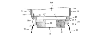
- FIG. 4 is a diagram showing an example of a distal end portion of an arm with a cover attached according to the first embodiment;
- FIG. 4 is a reference diagram for comparison showing an example of the distal end portion of the arm with no cover attached according to the first embodiment;
- FIG. 4 is a perspective view showing an example of the structure of a cover;
- FIG. 5 is an explanatory diagram showing an example of a change in shape of a cover when covering a spacer;
- FIG. 4 is a cross-sectional view showing a cross-sectional structure of a distal end portion of an arm for explaining an example of a procedure for attaching a cover according to the first embodiment;
- FIG. 4 is a diagram showing an example of a distal end portion of an arm with a cover attached according to the first embodiment;
- FIG. 4 is a reference diagram for comparison showing an example of the distal end portion of the arm with no cover attached according to the first embodiment;
- FIG. 4 is a perspective view showing an example of the structure of a
- FIG. 4 is a cross-sectional view showing a cross-sectional structure of a distal end portion of an arm for explaining an example of a procedure for attaching a cover according to the first embodiment
- FIG. 4 is a cross-sectional view showing a cross-sectional structure of a distal end portion of an arm for explaining an example of a procedure for attaching a cover according to the first embodiment
- 4 is a flow chart showing an example of a procedure for attaching a cover according to the first embodiment
- FIG. 10 is a diagram showing an example of the distal end portion of the arm with the cover attached in a modified example in which the arm is fixed to the flange by a straining force generated by the stretchability of the cover.
- FIG. 11 is a perspective view showing an example of the structure of a cover according to a modification;
- FIG. 11 is an explanatory diagram showing an example of a change in shape of a cover when covering a spacer in a modified example;
- FIG. 11 is a cross-sectional view showing the cross-sectional structure of the distal end portion of the arm for explaining an example of the procedure for attaching the cover according to the modified example;
- FIG. 11 is a cross-sectional view showing the cross-sectional structure of the distal end portion of the arm for explaining an example of the procedure for attaching the cover according to the modified example;
- FIG. 11 is a perspective view showing an example of the structure of a cover according to a modification;
- FIG. 11 is an explanatory diagram showing an example of a change in shape of a cover when covering a spacer in a modified example;
- FIG. 11 is a cross-sectional view showing the cross-sectional structure of the distal end portion of the arm for explaining an example of the procedure for attach
- FIG. 10 is a cross-sectional view showing the cross-sectional structure of the distal end portion of the arm in a modified example in which concave portions or convex portions are formed on the outer peripheral surface of the flange.
- FIG. 10 is a cross-sectional view showing the cross-sectional structure of the distal end portion of the arm in a modified example using a fastener.
- FIG. 10 is a cross-sectional view showing the cross-sectional structure of the distal end portion of the arm in a modified example in which a concave portion or a convex portion is formed on the outer peripheral surface of the flange, and the fastener has an engaging portion that engages with the concave portion or the convex portion.
- FIG. 10 is a diagram showing an example of a distal end portion of an arm and a proximal end portion of a hand with a cover attached in a modified example in which at least a portion of the hand is covered in addition to at least a portion of the arm.
- FIG. 11 is a reference diagram for comparison, showing an example of a distal end portion of an arm and a proximal end portion of a hand without a cover according to a modification;
- FIG. 11 is a perspective view showing an example of the structure of a cover according to a modification;
- FIG. 10 is a diagram showing an example of a distal end portion of an arm and a proximal end portion of a hand with a cover attached in a modified example in which at least a portion of the hand is covered in addition to at least a portion of the arm.
- FIG. 11 is a reference diagram for comparison, showing an example of a distal end portion of an arm and a proximal end portion of a hand without a cover
- FIG. 11 is a cross-sectional view showing the cross-sectional structure of the distal end portion of the arm for explaining an example of the procedure for attaching the cover according to the modified example;
- FIG. 11 is a cross-sectional view showing the cross-sectional structure of the distal end portion of the arm for explaining an example of the procedure for attaching the cover according to the modified example;
- FIG. 11 is a cross-sectional view showing the cross-sectional structure of the distal end portion of the arm for explaining an example of the procedure for attaching the cover according to the modified example;
- FIG. 11 is a cross-sectional view showing the cross-sectional structure of the distal end portion of the arm for explaining an example of the procedure for attaching the cover according to the modified example;
- FIG. 11 is a cross-sectional view showing the cross-sectional structure of the distal end portion of the arm for explaining an example of the procedure for attaching the cover according to the modified example;
- FIG. 11 is a cross-sectional view showing the cross-sectional structure of
- FIG. 11 is a cross-sectional view showing the cross-sectional structure of the distal end portion of the arm for explaining an example of the procedure for attaching the cover according to the modified example; It is a flow chart showing an example of the attachment procedure of the cover concerning a modification.
- FIG. 11 is a perspective view showing an example of a structure of a cover according to a modification in which only the base of the hand is covered with a cover fixed to a flange;
- FIG. 11 is a cross-sectional view showing the cross-sectional structure of the distal end portion of the arm for explaining an example of the procedure for attaching the cover according to the modified example;
- FIG. 10 is a diagram showing an example of a joint portion of an arm with a cover attached according to the second embodiment;
- FIG. 11 is a reference diagram for comparison showing an example of a joint portion of an arm without a cover according to the second embodiment
- FIG. 4 is a partial cross-sectional view showing an example of a cross-sectional structure near a joint portion of an arm with a broken line
- FIG. 12 is a perspective view showing an example of the structure of a cover attached to the wrist according to the second embodiment
- FIG. 4 is a partial cross-sectional view showing an example of a cross-sectional structure near a joint portion of a wrist for explaining an example of a procedure for attaching a cover to be attached to the wrist.
- FIG. 4 is a partial cross-sectional view showing an example of a cross-sectional structure near a joint portion of a wrist for explaining an example of a procedure for attaching a cover to be attached to the wrist.
- FIG. 11 is a perspective view showing an example of the structure of a cover attached to the upper arm according to the second embodiment;
- FIG. 10 is an explanatory diagram showing an example of change in shape of the cover attached to the upper arm according to the second embodiment when covering the housing member of the upper arm.
- FIG. 4 is a partial cross-sectional view showing an example of a cross-sectional structure near a joint portion of an upper arm by a broken line, for explaining an example of a procedure for attaching a cover to be attached to the upper arm;
- FIG. 4 is a partial cross-sectional view showing an example of a cross-sectional structure near a joint portion of an upper arm by a broken line, for explaining an example of a procedure for attaching a cover to be attached to the upper arm;
- FIG. 10 is a diagram showing an example of joints of an arm with a cover attached in a modification of the second embodiment in which the cover is configured as a single unit.
- FIG. 11 is a perspective view showing an example of the structure of a cover according to a modified example of the second embodiment;
- FIG. 11 is a partial cross-sectional view showing an example of a cross-sectional structure near a joint portion of an arm with broken lines for explaining an example of a procedure for attaching a cover according to a modification of the second embodiment;
- the first embodiment is an embodiment in which a cover is attached to the tip of an arm of a robot.
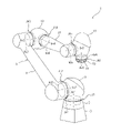
- FIG. 1 is a perspective view showing an example of the configuration of the robot according to the first embodiment.
- the robot 1 has a base 3 and an arm 5.
- the base 3 is installed, for example, on a floor, a frame, or the like.
- the arm 5 has a plurality of joints, and a hand (not shown in FIG. 1) is attached to the tip.
- the arm 5 has a base portion 7 , a swivel portion 9 , a lower arm portion 11 , an elbow portion 13 , an upper arm portion 15 , a wrist portion 17 and a flange 19 .
- the base portion 7 is fixed to the upper end portion of the base 3.
- the swivel portion 9 is supported by the upper end portion of the base portion 7 so as to be swivel around, for example, a rotation axis Ax1 parallel to the vertical up-down direction.
- the rotating portion 9 is driven to rotate about the rotation axis Ax1 with respect to the upper end portion of the base portion 7 by driving the actuator Ac1 provided at the joint portion Jt1 between the rotating portion 9 and the base portion 7 .
- the lower arm part 11 is supported on one side of the swivel part 9 so as to be swivelable around a rotation axis Ax2 perpendicular to the rotation axis Ax1.
- the lower arm 11 is driven to rotate about the rotation axis Ax2 with respect to one side of the rotating portion 9 by driving the actuator Ac2 provided at the joint Jt2 between the rotating portion 9 and the rotating portion 9 .
- the elbow portion 13 is supported on the distal end side of the lower arm portion 11 so as to be rotatable around a rotation axis Ax3 parallel to the rotation axis Ax2.
- the elbow portion 13 is driven to rotate about the rotation axis Ax3 with respect to the distal end side of the lower arm portion 11 by driving the actuator Ac3 provided at the joint portion Jt3 between the elbow portion 13 and the lower arm portion 11 .
- the upper arm 15 is supported on the distal end side of the elbow 13 so as to be rotatable about a rotation axis Ax4 perpendicular to the rotation axis Ax3.
- the upper arm 15 is driven to rotate about the rotation axis Ax4 with respect to the distal end of the elbow 13 by driving the actuator Ac4 provided at the joint Jt4 between the upper arm 15 and the elbow 13 .
- the wrist portion 17 is supported on the tip side of the upper arm portion 15 so as to be rotatable around a rotation axis Ax5 perpendicular to the rotation axis Ax4.
- the wrist portion 17 is driven to rotate about the rotation axis Ax5 with respect to the distal end side of the upper arm portion 15 by driving the actuator Ac5 provided at the joint portion Jt5 between the wrist portion 17 and the upper arm portion 15 .
- the flange 19 is rotatably supported on the distal end side of the wrist portion 17 about a rotation axis Ax6 perpendicular to the rotation axis Ax5 via a spacer 21 (an example of a pedestal; see FIG. 3, which will be described later).
- the flange 19 and the spacer 21 are driven to rotate about the rotation axis Ax6 with respect to the distal end of the wrist 17 by driving the actuator Ac6 provided at the joint Jt6 between the flange 19 and the spacer 21 .
- a cover 23 (a gray portion in FIG. 1) attached to the outer peripheral surface of the spacer 21 is illustrated. Details of the cover 23 will be described later.
- a hand (not shown in FIG. 1; see FIGS. 19 and 20 to be described later) is attached to the tip of the flange 19 .
- the hand rotates together with the flange 19 about the rotation axis Ax6.
- the robot 1 configured as described above is a 6-axis robot having six joints Jt1 to Jt6 each provided with actuators Ac1 to Ac6.
- Each of the actuators Ac1 to Ac6 that drives the joints Jt1 to Jt6 is composed of, for example, a motor and a speed reducer (not shown).
- a motor and a speed reducer not shown.
- the robot 1 collides with a person or an object it can immediately stop its operation, or can be operated in the direction opposite to the direction in which the external force acts. It is configured as a collaborative robot.
- the configuration of the robot 1 described above is an example, and is not limited to the content described above.
- the robot 1 may be a robot with axes other than 6 (for example, 5 or 7 axes).
- the robot 1 is not limited to the vertical articulated robot described above, and may be other types of robots such as a horizontal articulated robot or a parallel link robot.
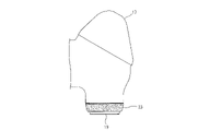
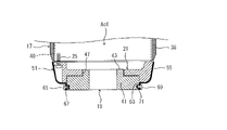
- FIG. 2 is a diagram showing an example of the tip portion of the arm 5 with the cover attached
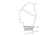
- FIG. 3 is a reference diagram for comparison, showing an example of the tip portion of the arm 5 without the cover attached. It is a diagram.
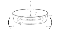
- FIG. 4 is a perspective view showing an example of the structure of the cover
- FIG. 5 is an explanatory view showing an example of change in shape of the cover when covering the spacer 21. As shown in FIG.
- the flange 19 is arranged at the tip of the wrist portion 17 of the arm 5 so as to be rotatable around the rotation axis.
- the spacer 21 to which the flange 19 is fixed is fixed to the actuator Ac6 with a plurality of bolts 25 (an example of first fasteners).
- a head portion 25 a of the bolt 25 is accommodated in a recess 27 formed in the outer peripheral surface of the spacer 21 .
- Head portions 25a of a plurality of bolts 25 are arranged so as to be exposed on the outer peripheral surface (an example of the outer surface) of the spacer 21 .
- a cover 23 covers the outer peripheral surface of the spacer 21, as shown in FIG.
- the outer peripheral surface of the spacer 21 is an example of at least part of the arm 5 .
- a cover 23 is fixed to the arm 5 . Details of the fixing structure will be described later.
- the cover 23 has elasticity.
- the cover 23 may be made of a material containing rubber, for example.
- the cover 23 may be made of, for example, a material containing resin or a material containing elastomer.
- the stretchability of the cover 23 it is possible to cover the arm 5 by following the surface shape of the arm 5 while reducing the gap, so that various shapes can be accommodated. Moreover, since the cover 23 has stretchability, the impact force when a person hits the robot 1 can be reduced.
- the cover 23 has a fixing portion 29 and a covering portion 31.
- the fixed portion 29 and the covering portion 31 are integrally formed, for example, so as to have the same thickness.
- the fixed portion 29 is a portion fixed to the arm 5 .
- the fixed portion 29 has a cylindrical cylindrical portion 33 and an annular collar portion 35 .
- Cylindrical portion 33 is formed to protrude to the outside of covering portion 31 from the edge of opening 36 formed in the bottom portion of covering portion 31 .
- the flange portion 35 is formed to extend inwardly from the edge of the tip portion of the cylindrical portion 33 .
- the fixing portion 29 is fixed to the flange 19 by being sandwiched between the flange 19 and the spacer 21, for example.
- the covering portion 31 (an example of the first covering portion) is a portion that covers the outer peripheral surface of the spacer 21 .
- the covering portion 31 is formed in a shape corresponding to the portion covered by the arm 5 .
- the covering portion 31 may be formed in a bowl shape corresponding to the outer peripheral surface of the spacer 21, for example.
- FIG. 4 shows an example of the initial shape of the cover 23, and the fixing portion 29 is fixed to the flange 19 in this state. From the state shown in FIG. 4 , as shown by an arrow 37 in FIG. cover the face
- the initial shape of the cover 23 is not limited to the shape shown in FIG. 4, and the shape shown in FIG. 5, for example, may be used as the initial shape.
- the covering portion 31 is first folded back to the side opposite to the fixing portion 29 to form the shape shown in FIG.
- the outer peripheral surface of the spacer 21 may be covered by folding back to the side.
- the fixing portion 29 and the covering portion 31 may be formed to have different thicknesses. For example, by making the fixing portion 29 thicker than the covering portion 31, the fixing function can be enhanced. In addition, for example, by making the thickness of the covering portion 31 thinner than that of the fixed portion 29, the flexibility of the covering portion 31 can be enhanced to improve the workability of the covering.
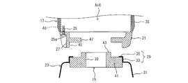
- FIG. 6 to 8 are cross-sectional views showing the cross-sectional structure of the distal end portion of the arm 5 for explaining an example of the procedure for attaching the cover according to the first embodiment.
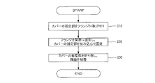
- FIG. 9 is a flowchart showing an example of a procedure for attaching the cover 23 (a robot manufacturing method).
- an actuator Ac6 is arranged inside the housing member 38 of the wrist portion 17.
- the spacer 21 is fixed to the output shaft 40 of the actuator Ac6 (for example, the output shaft of the speed reducer) with a plurality of bolts 25.
- the spacer 21 and the flange 19 are rotated relative to the housing member 38 by rotational driving of the output shaft 40 of the actuator Ac6.
- the flange 19 is a cylindrical member having a hollow portion 39, for example.
- the flange 19 may be a disk-shaped member having no hollow portion.
- the flange 19 has a body portion 41 and a projecting portion 43 .
- the fixing portion 29 of the cover 23 is fixed to the flange 19 in the state of the initial shape shown in FIG.
- the cylindrical portion 33 of the fixing portion 29 is attached to the outer peripheral surface of the body portion 41 of the flange 19
- the flange portion 35 of the fixing portion 29 is attached to the end surface of the body portion 41 on the side of the spacer 21 .
- the fixing portion 29 of the cover 23 covers the portion of the arm 5 that is not covered (the outer peripheral surface of the spacer 21).
- the peripheral length of the cylindrical portion 33 of the fixed portion 29 is set to be slightly shorter than the peripheral length of the outer peripheral surface of the main body portion 41, and the straining force generated by the elasticity of the cylindrical portion 33 causes the fixed portion 29 to move to the main body. It may be temporarily fixed to the portion 41 .
- the flange 19 is attached to the spacer 21 so that the body portion 41 fits into the recess 45 of the spacer 21 and the projecting portion 43 fits into the opening 47 of the spacer 21.
- the flange 19 (an example of a first member to be fixed) and the spacer 21 (an example of a second member to be fixed) are connected to each other by a plurality of bolts (an example of a second fastener, not shown) in the fitted state. ) to each other.
- the bolt is inserted toward the spacer 21 from the flange 19 side.
- the fixing portion 29 of the cover 23 is sandwiched between the flange 19 and the spacer 21 and fixed.
- the covering portion 31 of the cover 23 is folded back toward the spacer 21, so that the cover 23 assumes the shape shown in FIG. Thereby, the covering portion 31 covers the outer peripheral surface of the spacer 21 .
- Attachment of the cover 23 may be performed automatically by a robot, an automatic machine, or the like, or may be performed manually by an operator.
- step S10 the fixing portion 29 of the cover 23 is attached to the flange 19 (see FIG. 6).
- step S20 the flange 19 is fixed to the spacer 21 with a plurality of bolts, and the fixing portion 29 of the cover 23 is sandwiched and fixed between the flange 19 and the spacer 21 (see FIG. 7).
- step S30 the covering portion 31 of the cover 23 is folded back so that the covering portion 31 covers the outer peripheral surface of the spacer 21 (see FIG. 8). This flowchart is completed by the above.
- the above-described procedure is an example, and at least part of the above procedure may be deleted or changed, or procedures other than the above may be added. Moreover, the order of at least part of the above procedures may be changed, and a plurality of procedures may be combined into a single procedure.
- the bolt when fixing the flange 19 and the spacer 21, the bolt is inserted from the flange 19 side toward the spacer 21, but the bolt is inserted from the spacer 21 side toward the flange 19. may be inserted. In this case, with the spacer 21 removed from the wrist portion 17, the flange 19 with the cover 23 mounted thereon may be fixed to the spacer 21 as shown in FIGS.
- the bolt is inserted toward the flange 19 from the spacer 21 side.
- the spacer 21 to which the flange 19 is attached is fixed to the actuator Ac6 of the wrist portion 17 by the bolt 25, and the covering portion 31 of the cover 23 is folded back to cover the outer peripheral surface of the spacer 21 as shown in FIG. good.
- the robot 1 of the first embodiment includes a plurality of joints Jt1 to Jt6, an arm 5 to which a hand is attached at the distal end, and an arm 5 fixed to cover at least a part of the arm 5. , and an elastic cover 23 .
- the arm 5 has uneven portions such as the recessed portion 27 of the spacer 21, the head portion 25a of the bolt 25, or other cutouts, the uneven portions are exposed to the outside by covering with the cover 23. can be prevented. As a result, when a person touches the robot 1, the risk of being injured by the uneven portion can be reduced.
- the stretchability of the cover 23 it is possible to cover the arm 5 by following the surface shape of the arm 5 while reducing the gap, so that various shapes can be accommodated.
- the cover 23 has stretchability, the impact force when a person hits the robot 1 can be reduced. Therefore, safety can be improved.
- the cover 23 may be made of a material containing rubber.
- the elasticity of the rubber material can be used to reduce the impact force when a person hits the robot 1 .
- the rubber material covers at least a part of the surface of the arm 5, it is possible to give a more friendly impression to people than when the irregularities are exposed. Therefore, the appearance of the robot 1 can be improved.
- the cover 23 may have a fixing portion 29 fixed to the arm and a covering portion 31 covering at least part of the arm 5 .
- the cover 23 can have not only a covering function but also a fixing function for fixing to the arm 5. Also, the cover 23 can be divided into a portion that exhibits a fixing function and a portion that exhibits a covering function.
- the fixing function can be enhanced by, for example, reducing the peripheral length of the fixing portion 29 or making the thickness thicker than that of the covering portion 31 . Further, for example, by making the thickness of the covering portion 31 thinner than that of the fixed portion 29, it is possible to improve the workability of the covering. Therefore, the degree of freedom in designing the cover 23 can be improved.
- the arm 5 may have a flange 19 rotatably arranged around the rotation axis Ax6 at its distal end and to which a hand is attached. good too.
- the cover 23 fixed to the flange 19 can cover the portion of the arm 5 near the flange.
- the cover 23 fixed to the flange 19 can cover the portion of the arm 5 near the flange.
- the arm 5 may have a spacer 21 to which the flange 19 is fixed, arranged so that the head portion 25a of the bolt 25 is exposed on the outer surface. may have a covering portion 31 covering the outer surface of the spacer 21 .
- the head portion 25a of the bolt 25 arranged on the outer surface of the spacer 21 can be prevented from being exposed to the outside.
- the risk of being injured by the head portion 25a of the bolt 25, the recessed portion 27, or the like can be reduced.
- the arm 5 may have a flange 19 and a spacer 21 that are arranged near the joint Jt6 and fastened to each other by bolts. and the spacer 21 may be sandwiched and fixed.
- the fixing portion 29 of the cover 23 can seal between the flange 19 and the spacer 21 .
- the robot 1 having a plurality of joints Jt1 to Jt6 and an arm 5 to which a hand is attached at the distal end is manufactured by manufacturing a stretchable cover 23 having a fixing portion 29 and a covering portion 31.
- the fixing part 29 is fixed to the arm 5
- the covering part 31 is folded back toward the arm 5 to cover at least a part of the arm 5 .
- the stretchable cover 23 can be attached to the robot 1 by a simple procedure of fixing the fixing portion 29 and folding back the covering portion 31 to cover. As a result, the ease of attaching the cover 23 can be improved.
- the cover 23 is fixed by sandwiching the fixing portion 29 of the cover 23 between the flange 19 and the spacer 21, but the fixing method of the cover 23 is limited to this. is not.
- the fixing portion may be fixed to the arm 5 by a straining force generated by the stretchability of the cover.
- FIG. 10 is a diagram showing an example of the tip portion of the arm 5 with the cover according to this modified example attached.
- a cover 51 (the gray portion in FIG. 10 ; an example of a robot cover) is fixed to the outer peripheral surface of the flange 19 and covers the outer peripheral surface of the spacer 21 .
- a cover 51 is fixed to the arm 5 . Details of the fixing structure will be described later.
- the cover 51 has stretchability like the cover 23 described above.
- the cover 51 may be made of a material containing rubber, for example, or may be made of a material containing resin or an elastomer.
- FIG. 11 is a perspective view showing an example of the structure of the cover according to this modified example
- FIG. 12 is an explanatory diagram showing an example of change in the shape of the cover when the spacer 21 is covered.
- the cover 51 has a fixing portion 53 and a covering portion 55.
- the fixing portion 53 and the covering portion 55 are integrally formed, for example, so as to have the same thickness.
- the fixed portion 53 is a portion fixed to the arm 5 and is formed in a cylindrical shape.
- the fixing portion 53 is formed to protrude inside the covering portion 55 from the edge of an opening 57 formed in the bottom portion of the covering portion 55 .
- the fixed portion 53 is fixed so as to cover the outer peripheral surface of the flange 19 (an example of a member to be fixed).
- the peripheral length of the inner peripheral surface of the fixing portion 53 is formed to be shorter than the peripheral length of the outer peripheral surface of the flange 19 .
- the fixing portion 53 is fixed to the outer peripheral surface of the flange 19 by the straining force generated by the stretchability of the fixing portion 53 .
- the covering portion 55 (an example of the first covering portion) is a portion that covers the outer peripheral surface of the spacer 21, like the covering portion 31 described above.
- the covering portion 55 is formed in a bowl shape corresponding to the outer peripheral surface of the spacer 21 .
- FIG. 11 shows an example of the initial shape of the cover 51 , and the fixing portion 53 is fixed to the outer peripheral surface of the flange 19 while the covering portion 55 accommodates the fixing portion 53 inside. From the state shown in FIG. 11 , the covering portion 55 covers the outer peripheral surface of the spacer 21 by folding back the covering portion 55 to the side opposite to the fixing portion 53 as indicated by an arrow 59 in FIG. 12 .
- the initial shape of the cover 51 is not limited to the shape shown in FIG. 11, and for example, the shape shown in FIG. 12 may be used as the initial shape.
- the covering portion 55 is first folded back toward the fixing portion 53 to form the shape shown in FIG.
- the outer peripheral surface of the spacer 21 may be covered by folding back to the side.
- the fixing portion 53 and the covering portion 55 may be formed to have different thicknesses. For example, by making the fixing portion 53 thicker than the covering portion 55, the fixing function can be enhanced. Further, for example, by making the thickness of the covering portion 55 thinner than that of the fixed portion 53, the flexibility of the covering portion 55 can be enhanced, and the workability of the covering can be improved.
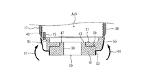
- FIGS. 13 and 14 are cross-sectional views showing the cross-sectional structure of the distal end portion of the arm 5 for explaining an example of the procedure for attaching the cover according to this modified example.
- FIGS. 13 and 14 the same components as in FIGS. 6 to 8 are denoted by the same reference numerals, and description thereof will be omitted as appropriate.
- the fixed portion 53 is fixed to the portion of the outer peripheral surface of the flange 19 exposed from the spacer 21 by straining force.
- the fixing portion 53 of the cover 51 covers the part of the arm 5 that is not covered (the outer peripheral surface of the spacer 21).
- the covering portion 55 of the cover 51 is folded toward the spacer 21 side, so that the cover 51 assumes the shape shown in FIG. cover the face
- the fixing part 53 can be fixed to the outer peripheral surface of the flange 19 by the tightening force generated by the elasticity of the fixing part 53 .
- the cover 51 can be fixed without using fasteners such as bolts, so that a boltless cover can be realized.
- the cover 51 since the cover 51 is fixed to the side surface of the flange 19 (the surface positioned perpendicular to the rotation axis Ax6; also called the outer peripheral surface), the cover 51 can be prevented from interfering with the hand attached to the flange 19.
- a concave portion or a convex portion may be formed on the outer peripheral surface of the flange 19 in order to further strengthen the fixation of the cover 51 by the fixing portion 53 .
- the shape of the concave portion or the convex portion is not particularly limited, for example, as shown in FIG. may be formed.
- the protrusions 63 may be separated at a plurality of locations in the circumferential direction, or recesses may be formed in addition to or instead of the protrusions.
- the fixed portion 53 of the cover 51 is fixed to the outer peripheral surface of the flange 19 so as to cover the convex portion 63 .
- the frictional force generated between the fixing portion 53 and the convex portion 63 is added to the straining force generated by the stretchability of the fixing portion 53 , thereby fixing the fixing portion 53 to the outer peripheral surface of the flange 19 more firmly. can do.
- a fastener for example, may be used.
- the configuration of the fastener is not particularly limited, for example, as shown in FIG.
- a band-like fastener 65 may also be used.
- the tightening force of the tightening tool 65 is added to the tightening force generated by the stretchability of the fixing part 53 , so that the fixing part 53 can be fixed more firmly to the outer peripheral surface of the flange 19 .
- a concave portion or a convex portion is formed on the outer peripheral surface of the flange 19, and an engaging portion for engaging the fastener with the concave portion or convex portion is provided.
- the shape of the concave or convex portion and the configuration of the fastener are not particularly limited, but for example, as shown in FIG. good too.
- the fastener 69 is, for example, a ring-shaped or band-shaped fastener wound around the outer periphery of the fixed portion 53 and has an engaging portion 71 that engages with the recess 67 .
- At least one of the recessed portion 67 and the engaging portion 71 may be separated at a plurality of locations in the circumferential direction.
- the fixing portion 53 of the cover 51 is sandwiched and fixed between the engaging portion 71 and the concave portion 67 that are engaged with each other.
- the tightening force generated by the stretchability of the fixing portion 53 is combined with the tightening force of the fastener 69 and the frictional force generated by the engagement between the engaging portion 71 of the fastener 69 and the concave portion 67 of the flange 19.
- the fixed portion 53 can be fixed to the outer peripheral surface of the flange 19 more firmly.
- FIG. 18 shows an example of the mounting procedure (robot manufacturing method) of the cover 51 according to this modified example. Attachment of the cover 51 may be performed automatically by a robot, an automatic machine, or the like, or may be performed manually by an operator.
- the fixing portion 53 of the cover 51 is attached to the flange 19 (see FIG. 13).
- the fixing portion 53 is fixed to the outer peripheral surface of the flange 19 so as to cover the convex portion 63 (see FIG. 15).
- the fastener 65 After the fixing part 53 is attached to the flange 19, the fastener 65 is wound around the outer circumference of the fixing part 53, and the fixing part 53 is attached to the outer peripheral surface of the flange 19. It is tightened (see Figure 16).
- step S120 the covering portion 55 of the cover 51 is folded back so that the covering portion 55 covers the outer peripheral surface of the spacer 21 (see FIG. 14). This flowchart is completed by the above.
- the above-described procedure is an example, and at least part of the above procedure may be deleted or changed, or procedures other than the above may be added. Moreover, the order of at least part of the above procedures may be changed, and a plurality of procedures may be combined into a single procedure.
- the cover covers a portion of the arm 5, but the cover may cover at least a portion of the hand in addition to a portion of the arm 5.
- FIG. 19 is a diagram showing an example of the distal end portion of the arm 5 and the proximal end portion of the hand with the cover according to this modified example attached
- FIG. 20 is a reference diagram for comparison, in which the cover is not attached.
- FIG. 10 is a diagram showing an example of the distal end portion of the arm 5 and the proximal end portion of the hand in a state;
- FIGS. 19 and 20 the same components as in FIGS. 2 and 3 are denoted by the same reference numerals, and description thereof will be omitted as appropriate.
- a hand 73 is attached to the tip of the flange 19 in this modification.
- the hand 73 is a tool corresponding to the work performed or handled by the robot 1, and is also called an end effector.
- the hand 73 may have, for example, a plurality of fingers or claws capable of gripping the work, or may have, for example, a vacuum pad or magnet capable of attracting the work.
- the hand 73 may be a spatula-shaped hand or the like.
- the hand 73 has a base portion 75 fixed to the flange 19 and a main body portion 77 .
- the base portion 75 is fixed to the body portion 77 with a plurality of bolts 79 .
- a head portion 79 a of the bolt 79 is accommodated in a recess 81 formed in the outer peripheral surface of the base portion 75 .
- Head portions 79 a of a plurality of bolts 79 are arranged to be exposed on the outer peripheral surface (an example of the outer surface) of the base portion 75 .
- the head portion 25a of the bolt 25 is housed so as to be exposed in the recess 27 formed in the outer peripheral surface of the spacer 21 is the same as in the above-described first embodiment.
- the concave portion 81 of the base portion 75, the head portion 79a of the bolt 79, the concave portion 27 of the spacer 21, the head portion 25a of the bolt 25, and other uneven portions such as notches are exposed to the outside. Therefore, when the worker touches the robot 1, there is a possibility that the worker may be injured by the uneven portion.
- a cover 83 (the gray portion in FIG. 19; an example of a robot cover) covers the outer peripheral surface of the spacer 21 and the outer periphery of the base 75 of the hand 73. cover the surface.
- the outer peripheral surface of the base portion 75 is an example of at least a portion of the hand 73 and a portion of the hand 73 on the flange side.
- a cover 83 is fixed to the arm 5 . Details of the fixing structure will be described later.
- the cover 83 has stretchability like the covers 23 and 51 described above.
- the cover 83 may be made of a material containing rubber, for example, or may be made of a material containing resin or an elastomer.
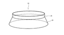
- FIG. 21 is a perspective view showing an example of the structure of the cover according to this modified example.
- the cover 83 has a fixing portion 85, a first covering portion 87, and a second covering portion 89.
- the fixing portion 85, the first covering portion 87, and the second covering portion 89 are integrally formed, for example, so as to have the same thickness.
- the fixed portion 85 is a portion fixed to the arm 5 and is formed in a cylindrical shape.
- the fixing portion 85 is formed to protrude from the edge of the opening 91 formed in the bottom of the first covering portion 87 toward the second covering portion 89 .
- the fixed portion 85 is fixed so as to cover the outer peripheral surface of the flange 19 .
- the peripheral length of the inner peripheral surface of the fixing portion 85 is formed to be shorter than the peripheral length of the outer peripheral surface of the flange 19 .
- the fixing portion 85 is fixed to the outer peripheral surface of the flange 19 by the straining force generated by the stretchability of the fixing portion 85 .
- the first covering portion 87 is a portion that covers the outer peripheral surface of the spacer 21, like the covering portions 31 and 55 described above.
- the first covering portion 87 is formed on one side of the fixing portion 85 and has a bowl shape corresponding to the outer peripheral surface of the spacer 21 .
- the second covering portion 89 is a portion that covers the outer peripheral surface of the base portion 75 of the hand 73 .
- the second covering portion 89 is formed on the other side of the fixing portion 85 and is formed in a shape corresponding to the portion covered by the hand 73 .
- the second covering portion 89 is formed, for example, in the shape of a hollow truncated cone corresponding to the outer peripheral surface of the base portion 75 of the hand 73 .
- the second covering portion 89 is formed to protrude from the edge of the fixing portion 85 on the side opposite to the first covering portion 87 toward the side opposite to the first covering portion 87 while enlarging the diameter. 21 shows an example of the initial shape of the cover 83. As shown in FIG.
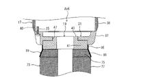
- FIGS. 22 to 26 are cross-sectional views showing the cross-sectional structure of the distal end portion of the arm 5 for explaining an example of the procedure for attaching the cover according to this modified example.
- FIGS. 22 to 26 the same components as in FIGS. 6 to 8, 13 and 14 are denoted by the same reference numerals, and description thereof will be omitted as appropriate.
- the cover 83 has the first covering part 87 folded back from the initial shape shown in FIG. In the folded state, the fixed portion 85 of the cover 83 is fixed to a portion of the outer peripheral surface of the flange 19 exposed from the spacer 21 by straining force.
- the first covering portion 87 of the cover 83 is folded back toward the spacer 21, so that the cover 83 assumes the shape shown in FIG. It covers the outer peripheral surface of the spacer 21 .
- the cover 83 has the second covering portion 89 folded back toward the outer circumference of the first covering portion 87 (the spacer 21 side).
- a hand 73 is attached to the tip of the flange 19 as shown in FIG.
- the second covering portion 89 of the cover 83 is folded back toward the hand 73, so that the cover 83 assumes the shape shown in FIG. It covers the outer peripheral surface of the base 75 of 73 .
- the initial shape of the cover 83 is not limited to the shape shown in FIG. 21, and for example the shape shown in FIG. 22 may be used as the initial shape.
- the procedure for folding back the first covering portion 87 to the outer peripheral side of the second covering portion 89 (the side opposite to the spacer 21) is not necessary.
- the fixing portion 85 and the first covering portion 87 and the second covering portion 89 may be formed to have different thicknesses. For example, by making the fixing portion 85 thicker than the first covering portion 87 and the second covering portion 89, the fixing function can be enhanced.
- the thickness of the first covering portion 87 and the second covering portion 89 thinner than that of the fixing portion 85, the flexibility of the first covering portion 87 and the second covering portion 89 is increased, and the workability of the covering is improved. etc. will be possible.
- FIG. 27 shows an example of the mounting procedure (robot manufacturing method) of the cover 83 according to this modified example. Attachment of the cover 83 may be automatically performed by a robot, an automatic machine, or the like, or may be manually performed by an operator.
- step S210 the first covering portion 87 of the cover 83 is folded back from the initial shape shown in FIG. 21 to the outer peripheral side of the second covering portion 89 (the side opposite to the spacer 21) (see FIG. 22). .
- step S220 the fixing portion 85 of the cover 83 is fixed to the portion of the outer peripheral surface of the flange 19 exposed from the spacer 21 by tightening force (see FIG. 22).
- step S230 the first covering portion 87 of the cover 83 is folded back toward the spacer 21, so that the outer peripheral surface of the spacer 21 is covered with the first covering portion 87 (see FIG. 23).
- step S240 the second covering portion 89 of the cover 83 is folded back toward the outer circumference of the first covering portion 87 (toward the spacer 21) (see FIG. 24).
- the hand 73 is attached to the tip of the flange 19 (see FIG. 25).
- step S260 the second covering portion 89 of the cover 83 is folded back toward the hand 73, so that the outer peripheral surface of the base portion 75 of the hand 73 is covered with the second covering portion 89.
- the above-described procedure is an example, and at least part of the above procedure may be deleted or changed, or procedures other than the above may be added. Moreover, the order of at least part of the above procedures may be changed, and a plurality of procedures may be combined into a single procedure. For example, when the initial shape of the cover 83 is the shape shown in FIG. 22, the step S210 of folding back the first covering portion 87 to the outer peripheral side of the second covering portion 89 (the side opposite to the spacer 21) is unnecessary.
- the cover 83 has the second covering portion 89 that covers a portion of the hand 73 on the flange side.
- the cover 83 includes a fixed portion 85 fixed to the flange 19, a first covering portion 87 formed on one side of the fixed portion 85 and covering the outer peripheral surface of the spacer 21, and a and a second covering portion 89 that is formed on the other side and covers the outer peripheral surface of the base portion 75 of the hand 73 .
- the fixing portion 85 can be shared between the first covering portion 87 covering the outer peripheral surface of the spacer 21 and the second covering portion 89 covering the outer peripheral surface of the base portion 75 of the hand 73 .
- This allows the single cover 83 to cover both the outer peripheral surface of the spacer 21 and the outer peripheral surface of the base portion 75 . Therefore, compared with the case where two covers are used, it is possible to improve maintainability by facilitating attachment and replacement of the covers, simplify the configuration by reducing the number of parts, and reduce costs.
- the cover 83 covers both the spacer 21 of the arm 5 and the base 75 of the hand 73.
- the cover fixed to the flange 19. can be In this case, as shown in FIGS. 28 and 29, the fixing portion 85 of the cover 99 having the fixing portion 85 and the second covering portion 89 is fixed to the flange 19, and the base portion 75 of the hand 73 is supported by the second covering portion 89. may be coated.
- Second Embodiment> 2nd Embodiment is embodiment in the case of attaching a cover to joint parts other than the front-end
- a cover is attached to the joint Jt5
- covers having a similar configuration may be attached to the other joints Jt1 to Jt4.
- FIG. 30 is a diagram showing an example of the joint Jt5 of the arm 5 with the cover attached
- FIG. 31 is a reference diagram for comparison, showing an example of the joint Jt5 of the arm 5 without the cover attached. It is a figure showing.
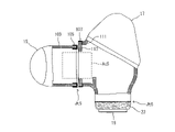
- FIG. 32 is a partial cross-sectional view showing an example of a cross-sectional structure near the joint Jt5 of the arm 5 with a broken line.
- the wrist portion 17 rotates about the rotation axis Ax5 with respect to the distal end side of the upper arm portion 15 by driving the actuator Ac5 provided at the joint portion Jt5 between the wrist portion 17 and the upper arm portion 15. driven.
- a positioning groove 101 is formed in the vicinity of the joint Jt5 of the upper arm 15, and a positioning groove 101 is formed in the vicinity of the joint Jt5 of the wrist 17. is formed with a groove 103 for positioning.
- the grooves 101 and 103 are formed, for example, as linear grooves parallel to the rotation axis Ax5.
- the grooves 101 and 103 relatively move in the circumferential direction around the rotation axis Ax5 as the wrist portion 17 rotates relative to the upper arm portion 15 .
- the circumferential position (rotational angle) at which the grooves 101 and 103 coincide is stored in, for example, a robot controller (not shown) as the origin of the rotational angle of the actuator Ac5.
- the origin is used, for example, when the robot 1 is installed.
- a cover 105 covers the outer peripheral surface of the upper arm 15 in the vicinity of the joint Jt5
- a cover 107 covers the outer peripheral surface of the wrist portion 17 in the vicinity of the joint portion Jt5.
- the portion of the upper arm 15 near the joint Jt5 and the portion of the wrist 17 near the joint Jt5 are examples of at least a portion of the arm 5 .
- Covers 105 and 107 are fixed to arm 5 .
- the cover 105 is fixed to the housing member 109 of the upper arm 15, and the cover 107 is sandwiched and fixed between the first housing member 111 and the second housing member 113 of the wrist section 17. .
- the covers 105, 107 are stretchable.
- the covers 105 and 107 may be made of a material containing rubber, for example, or may be made of a material containing resin or an elastomer.
- Covers 105 and 107 cover the outer peripheral surface of the portion of the upper arm 15 near the joint Jt5 and the outer peripheral surface of the portion of the wrist 17 near the joint Jt5, respectively. can be prevented from being exposed to the robot 1, and the risk of being injured when the worker touches the robot 1 can be reduced.
- the stretchability of the covers 105 and 107 it is possible to cover the arm 5 by following the surface shape of the arm 5 while reducing the gap, so that various shapes can be accommodated.
- the covers 105 and 107 have stretchability, the impact force when a person hits the robot 1 can be reduced.
- a concave portion or the like for accommodating the bolt head may be formed in the vicinity of the joint portion Jt5 as in the first embodiment described above.
- FIG. FIG. 33 is a perspective view showing an example of the structure of the cover 107 attached to the wrist 17, and FIGS.
- FIG. 10 is a partial cross-sectional view showing an example of the cross-sectional structure of the portion 17 near the joint Jt5 with a broken line.
- 36 and 37 are perspective views showing an example of the structure of the cover 105 attached to the upper arm 15, and FIGS. 38 and 39 are for explaining an example of the procedure for attaching the cover 105 attached to the upper arm 15.
- 2 is a partial cross-sectional view showing an example of the cross-sectional structure of the vicinity of the joint Jt5 of the upper arm 15 with a broken line.
- the cover 107 has an annular fixed portion 115 and a cylindrical covering portion 117 .
- the fixing portion 115 and the covering portion 117 are integrally formed and formed to have the same thickness, for example.
- the fixed part 115 is a part fixed to the arm 5 .
- Fixing portion 115 is formed to extend inwardly from the edge of the distal end portion of covering portion 117 .
- the fixed portion 115 is fixed by being sandwiched between the first housing member 111 and the second housing member 113 of the wrist portion 17 .
- the covering portion 117 is a portion that covers the outer peripheral surface of the second housing member 113 .
- the cover portion 117 is formed in a shape corresponding to the portion covered by the arm 5 .
- the covering portion 117 is formed in a cylindrical shape corresponding to the outer peripheral surface of the second housing member 113, for example.
- FIG. 33 shows an example of the initial shape of the cover 107, and the fixing portion 115 is fixed to the wrist portion 17 in this state.
- the second housing member 113 is removed from the first housing member 111.
- the cover 107 is in the initial shape state shown in FIG. 33, the covering portion 117 is attached to the outer peripheral surface of the second housing member 113, and the fixing portion 115 is attached to the first housing member 111 side of the second housing member 113. attached to the end face of the At this time, the circumferential length of the covering portion 117 is set to be slightly shorter than the circumferential length of the outer peripheral surface of the second housing member 113, and the elastic force generated by the elasticity of the covering portion 117 causes the covering portion 117 to move to the second position. It may be temporarily fixed to the housing member 113 .
- the second housing member 113 is attached to the first housing member 111, as shown in FIG.
- the second housing member 113 (an example of a first member to be fixed) and the first housing member 111 (an example of a second member to be fixed) are connected by a plurality of bolts (an example of a second fastener, not shown). ) to each other.
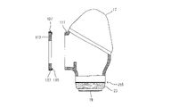
- the bolt may be inserted toward the first housing member 111 from the second housing member 113 side, or may be inserted toward the second housing member 113 from the first housing member 111 side.
- a fixed portion 115 of the cover 107 is sandwiched and fixed between the first housing member 111 and the second housing member 113 .
- the covering portion 117 covers the outer peripheral surface of the second housing member 113 .
- the procedure for attaching the cover 107 is not limited to the above.
- the covering portion 117 of the cover 107 is attached to the second housing member 113 side.
- the outer peripheral surface of the second housing member 113 may be covered by folding back.
- the fixing portion 115 and the covering portion 117 may be formed to have different thicknesses. For example, by making the fixing portion 115 thicker than the covering portion 117, the fixing function can be enhanced. Further, for example, by making the thickness of the covering portion 117 thinner than that of the fixed portion 115, the flexibility of the covering portion 117 can be enhanced, and the workability of covering can be improved.
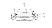
- the cover 105 includes a cylindrical fixing portion 119, a cylindrical covering portion 121 having a larger diameter than the fixing portion 119, and an end portion of the fixing portion 119 and an end portion of the covering portion 121. It has an annular connecting portion 123 that The fixing portion 119, the covering portion 121, and the connecting portion 123 are integrally formed, for example, so as to have the same thickness.
- the connecting portion 123 is formed to extend from the edge of the tip portion of the covering portion 121 toward the inner peripheral side.
- the radial width of the connecting portion 123 is formed to be substantially the same as the thickness of the housing member 109 of the upper arm portion 15 .
- the fixed portion 119 is a portion fixed to the arm 5 . Fixing portion 119 is formed to protrude from the edge of opening 125 formed in connecting portion 123 to the outside of covering portion 121 .
- the covering portion 121 is a portion that covers the outer peripheral surface of the housing member 109 of the upper arm 15 near the joint Jt5.
- the covering portion 121 is formed in a shape corresponding to the covered portion of the arm 5 .
- the covering portion 121 is formed, for example, in a cylindrical shape corresponding to the outer peripheral surface of the housing member 109 .
- FIG. 36 shows an example of the initial shape of the cover 105. In this state, the covering portion 121 is attached to the outer peripheral surface of the housing member 109.
- FIG. The peripheral length of the covering portion 121 is shorter than the peripheral length of the outer peripheral surface of the housing member 109, and is fixed to the outer peripheral surface of the housing member 109 by the straining force generated by the elasticity of the covering portion 121. .
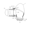
- the covering portion 121 also functions as a fixing portion. From the state shown in FIG. 36, as indicated by an arrow 127 in FIG. cover. As a result, the covering portion 121 and the fixing portion 119 sandwich the end portion of the housing member 109 from both sides, and the cover 105 is fixed to the end portion of the housing member 109 .
- the cover 105 is in the initial shape shown in FIG. It is attached to the end face on the part Jt5 side.
- the fixing portion 119 of the cover 105 is folded back inside the housing member 109, so that the cover 105 assumes the shape shown in FIG. As a result, the cover 105 is fixed to the end portion of the housing member 109 and the covering portion 121 covers the outer peripheral surface of the end portion of the housing member 109 .
- the fixing portion 119 of the cover 105 may be eliminated, and the cover 105 may have only the covering portion 121 and the connecting portion 123 .
- the covering portion 121 also functions as the fixing portion and serves as the fixing portion.
- concave portions or convex portions may be formed on the outer peripheral surface of the housing member 109 in order to fix the cover 105 more firmly.
- a fastener that is wound around the outer circumference of the covering portion 121 of the cover 105 and tightens the covering portion 121 against the outer peripheral surface of the housing member 109 may be used.
- the fastener may have an engaging portion that engages with a concave portion or a convex portion formed on the outer peripheral surface of the housing member 109. As shown in FIG.
- two covers 105 and 107 are provided as covers to be attached to the joint Jt5. It can be covered without impeding the driving of Jt5.
- FIG. 40 is a view showing an example of the joint Jt5 of the arm 5 with the cover according to this modification attached
- FIG. 41 is a perspective view showing an example of the structure of the cover according to this modification
- FIG. 4 is a partial cross-sectional view showing an example of a cross-sectional structure near a joint Jt5 of an arm 5 with a broken line.
- a cover 131 (an example of a robot cover) having a single configuration covers the outer peripheral surface of the upper arm 15 near the joint Jt5 and the wrist 17. It covers both outer peripheral surfaces of the vicinity of the joint Jt5.
- a cover 131 is fixed to the arm 5 .
- the cover 131 has elasticity.
- the cover 131 may be made of a material containing rubber, for example, or may be made of a material containing resin or an elastomer.
- the cover 131 has an annular fixing portion 133 and a cylindrical covering portion 135 .
- the fixing portion 133 and the covering portion 135 are integrally formed, for example, so as to have the same thickness.
- the fixed part 133 is a part fixed to the arm 5 .
- the fixing portion 133 is formed to extend from the edge of the tip portion of the covering portion 135 toward the inner peripheral side.
- the fixing portion 133 is fixed by being sandwiched between the first housing member 111 and the second housing member 113 of the wrist portion 17 .
- the covering portion 135 is a portion that covers the outer peripheral surface of the end portion of the upper arm portion 15 and the outer peripheral surface of the end portion of the wrist portion 17 .
- the covering portion 135 is formed in a shape corresponding to the covered portion of the arm 5 .
- the covering portion 135 is formed in a cylindrical shape corresponding to, for example, the outer peripheral surface of the end portion of the upper arm portion 15 and the outer peripheral surface of the end portion of the wrist portion 17 .
- FIG. 41 shows an example of the initial shape of the cover 131, and the fixing portion 133 is fixed to the wrist portion 17 in this state.
- the cover 131 is fixed to the wrist portion 17 by sandwiching the fixing portion 133 between the first housing member 111 and the second housing member 113 of the wrist portion 17 .
- the cover 131 covers the outer peripheral surface of the second housing member 113 of the wrist portion 17 in close contact, but covers the outer peripheral surface of the housing member 109 of the upper arm portion 15 via a clearance.
- the cover 131 is fixed to one portion (wrist portion 17) of the joint portion Jt5 and is provided with a clearance to the other portion (upper arm portion 15).
- both the groove 101 of the upper arm 15 and the groove 103 of the wrist 17, which rotate relative to each other, can be covered by the single cover 131 without impeding the driving of the joint Jt5. Therefore, compared with the case where two covers are used, it is possible to improve maintainability by facilitating attachment and replacement of the covers, simplify the configuration by reducing the number of parts, and reduce costs.
- the problems to be solved by the above-described first and second embodiments and the effects of the first and second embodiments are not limited to the contents described above. That is, the above-described first and second embodiments can solve problems not described above, achieve effects not described above, solve only a part of the problems described above, Only some of the described effects may be achieved.
Landscapes
- Engineering & Computer Science (AREA)
- Robotics (AREA)
- Mechanical Engineering (AREA)
- Manipulator (AREA)
Abstract
【課題】安全性を向上することが可能なロボット、ロボット用カバー、及びロボットの製造方法を提供する。 【解決手段】ロボット1は、複数の関節部Jt1~Jt6を備え、先端部にハンドが取り付けられるアーム5と、アーム5に固定され、アーム5の少なくとも一部を覆う、伸縮性を有するカバー23とを有する。カバー23は、ゴムを含む材質で構成されており、アームに固定される固定部29と、アーム5の少なくとも一部を覆う被覆部31とを有する。
Description
開示の実施形態は、ロボット、ロボット用カバー、及びロボットの製造方法に関する。
特許文献1には、人とロボットが協働作業を行うロボットシステムが記載されている。
人協働ロボットでは、安全性の観点から、ボルトヘッドや切欠き等の凹凸がロボットの外表面に露出しないことが好ましく、より高い安全性が求められていた。
本発明はこのような問題点に鑑みてなされたものであり、安全性を向上することが可能なロボット、ロボット用カバー、及びロボットの製造方法を提供することを目的とする。
上記課題を解決するため、本発明の一の観点によれば、複数の関節部を備え、先端部にハンドが取り付けられるアームと、前記アームに固定され、前記アーム及び前記ハンドの少なくとも一方の少なくとも一部を覆う、伸縮性を有するカバーと、を有する、ロボットが適用される。
また、本発明の別の観点によれば、複数の関節部を備え、先端部にハンドが取り付けられるアームを有するロボットに取り付けられるロボット用カバーであって、伸縮性を有し、前記アームに固定される固定部と、前記アーム及び前記ハンドの少なくとも一方の少なくとも一部を覆う被覆部と、を有する、ロボット用カバーが適用される。
また、本発明の別の観点によれば、複数の関節部を備え、先端部にハンドが取り付けられるアームを有するロボットの製造方法であって、固定部と被覆部を備え伸縮性を有するカバーの前記固定部を前記アームに固定することと、前記被覆部を前記アーム側又は前記ハンド側に折り返し、前記アーム及び前記ハンドの少なくとも一方の少なくとも一部を覆うことと、を有する、ロボットの製造方法が適用される。
本発明のロボット等によれば、安全性を向上することができる。
以下、実施の形態について図面を参照しつつ説明する。
<1.第1実施形態>
第1実施形態は、ロボットのアームの先端部にカバーを取り付ける場合の実施形態である。
第1実施形態は、ロボットのアームの先端部にカバーを取り付ける場合の実施形態である。
(1-1.ロボットの構成)
図1を参照しつつ、第1実施形態に係るロボットの構成の一例について説明する。図1は、第1実施形態に係るロボットの構成の一例を表す斜視図である。
図1を参照しつつ、第1実施形態に係るロボットの構成の一例について説明する。図1は、第1実施形態に係るロボットの構成の一例を表す斜視図である。
図1に示すように、ロボット1は、基台3と、アーム5とを有する。基台3は、例えば床や架台等に設置される。アーム5は、複数の関節部を備えており、先端部にハンド(図1では図示省略)が取り付けられる。アーム5は、ベース部7と、旋回部9と、下腕部11と、肘部13と、上腕部15と、手首部17と、フランジ19とを有する。
ベース部7は、基台3の上端部に固定されている。旋回部9は、ベース部7の上端部に、例えば鉛直上下方向に平行な回転軸Ax1周りに旋回可能に支持されている。旋回部9は、ベース部7との間の関節部Jt1に設けられたアクチュエータAc1の駆動により、ベース部7の上端部に対し、回転軸Ax1周りに旋回駆動される。
下腕部11は、旋回部9の一方側の側部に、回転軸Ax1に垂直な回転軸Ax2周りに旋回可能に支持されている。下腕部11は、旋回部9との間の関節部Jt2に設けられたアクチュエータAc2の駆動により、旋回部9の一方側の側部に対し、回転軸Ax2周りに旋回駆動される。
肘部13は、下腕部11の先端側に、回転軸Ax2に平行な回転軸Ax3周りに旋回可能に支持されている。肘部13は、下腕部11との間の関節部Jt3に設けられたアクチュエータAc3の駆動により、下腕部11の先端側に対し、回転軸Ax3周りに旋回駆動される。
上腕部15は、肘部13の先端側に、回転軸Ax3に垂直な回転軸Ax4周りに回動可能に支持されている。上腕部15は、肘部13との間の関節部Jt4に設けられたアクチュエータAc4の駆動により、肘部13の先端側に対し、回転軸Ax4周りに回動駆動される。
手首部17は、上腕部15の先端側に、回転軸Ax4に垂直な回転軸Ax5周りに旋回可能に支持されている。手首部17は、上腕部15との間の関節部Jt5に設けられたアクチュエータAc5の駆動により、上腕部15の先端側に対し、回転軸Ax5周りに旋回駆動される。
フランジ19は、手首部17の先端側に、間座21(台座の一例。後述の図3参照)を介して回転軸Ax5に垂直な回転軸Ax6周りに回動可能に支持されている。フランジ19及び間座21は、手首部17との間の関節部Jt6に設けられたアクチュエータAc6の駆動により、手首部17の先端側に対し、回転軸Ax6周りに回動駆動される。図1では、間座21の外周面に装着されたカバー23(図1中グレーの部分)が図示されている。カバー23の詳細については後述する。
ハンド(図1では図示省略。後述の図19及び図20参照)は、フランジ19の先端に取り付けられる。ハンドは、フランジ19の回転軸Ax6周りの回動により、フランジ19と共に回転軸Ax6周りに回動する。
以上の構成であるロボット1は、アクチュエータAc1~Ac6の各々を備えた6つの関節部Jt1~Jt6を有する6軸ロボットである。各関節部Jt1~Jt6を駆動するアクチュエータAc1~Ac6の各々は、例えばモータ及び減速機(図示省略)等により構成されている。ロボット1は、例えば人や物に衝突した場合には直ちに動作を停止させたり、外力が作用した方向と逆方向に動作させる等が可能となっており、作業者と共に稼働することが可能な人協働ロボットとして構成されている。
上記では、アーム5の長手方向(あるいは延在方向)に沿った回転軸周りの回転を「回動」と呼び、アーム5の長手方向(あるいは延在方向)に垂直な回転軸周りの回転を「旋回」と呼んで区別している。
なお、上述したロボット1の構成は一例であり、上述の内容に限定されるものではない。例えば、ロボット1を6軸以外(例えば5軸や7軸等)のロボットとしてもよい。また、ロボット1は上述した垂直多関節型のロボットに限定されるものではなく、例えば水平多関節型のロボットやパラレルリンクロボット等、他のタイプのロボットとしてもよい。
(1-2.カバーの構成)
図2~図5を参照しつつ、第1実施形態に係るカバーの構成の一例について説明する。図2は、カバーを装着した状態のアーム5の先端部の一例を表す図、図3は比較のための参考図であり、カバーを装着していない状態のアーム5の先端部の一例を表す図である。図4は、カバーの構造の一例を表す斜視図、図5は、間座21を被覆する際のカバーの形状の変化の一例を表す説明図である。
図2~図5を参照しつつ、第1実施形態に係るカバーの構成の一例について説明する。図2は、カバーを装着した状態のアーム5の先端部の一例を表す図、図3は比較のための参考図であり、カバーを装着していない状態のアーム5の先端部の一例を表す図である。図4は、カバーの構造の一例を表す斜視図、図5は、間座21を被覆する際のカバーの形状の変化の一例を表す説明図である。
図2及び図3に示すように、フランジ19は、アーム5の手首部17の先端部に回転軸周りに回転可能に配置されている。カバーを装着していない状態を表す図3に示すように、フランジ19が固定された間座21は、複数のボルト25(第1の締結具の一例)によりアクチュエータAc6に固定されている。ボルト25のヘッド部25aは、間座21の外周面に形成された凹部27に収容されている。間座21の外周面(外表面の一例)には、複数のボルト25のヘッド部25aが露出するように配置されている。ロボット1が作業者と共に稼働する場合、間座21の凹部27、ボルト25のヘッド部25a、その他切欠き等の凹凸部が外部に露出することで、作業者がロボット1に触れた際に凹凸部で外傷を負う可能性がある。
本実施形態のロボット1では、図2に示すように、カバー23(ロボット用カバーの一例)が間座21の外周面を被覆する。間座21の外周面はアーム5の少なくとも一部の一例である。カバー23は、アーム5に固定されている。固定構造の詳細については後述する。カバー23は伸縮性を有している。カバー23は、例えばゴムを含む材質で構成されてもよい。その他にも、カバー23は、例えば樹脂を含む材質やエラストマーを含む材質で構成されてもよい。間座21の外表面をカバー23で覆うことにより、凹部27やボルト25のヘッド部25a等の凹凸部が外部に露出することを防止でき、作業者がロボット1に触れた際に外傷を負うリスクを低減できる。また、カバー23の伸縮性を利用して、アーム5の表面形状に倣わせて隙間を低減しつつ覆うことが可能となり、多種多様な形状に対応できる。また、カバー23が伸縮性を有するため、人がロボット1に当たった際の衝撃力を低減できる。
図4及び図5に示すように、カバー23は、固定部29と被覆部31とを有する。固定部29と被覆部31は、一体として形成されており、例えば同じ厚みを有するように形成されている。固定部29は、アーム5に固定される部分である。固定部29は、円筒状の円筒部33と、円環状のつば部35とを有する。円筒部33は、被覆部31の底部に形成された開口部36の縁から被覆部31の外側に突出するように形成されている。つば部35は、円筒部33の先端部の縁から内周側に延びるように形成されている。固定部29は、例えばフランジ19と間座21に挟まれることでフランジ19に固定される。
被覆部31(第1被覆部の一例)は、間座21の外周面を覆う部分である。被覆部31は、アーム5の覆う部分に対応した形状に形成されている。被覆部31は、例えば間座21の外周面に対応したお椀型の形状に形成されてもよい。図4は、カバー23の初期形状の一例を表しており、この状態で固定部29がフランジ19に固定される。図4に示す状態から、図5の矢印37に示すように、被覆部31が固定部29を内側に収容するように固定部29側に折り返されることで、被覆部31が間座21の外周面を覆う。
なお、カバー23の初期形状は図4に示す形状に限定されるものではなく、例えば図5に示す形状を初期形状としてもよい。この場合、最初に被覆部31を固定部29とは反対側に折り返すことで図4に示す形状とし、固定部29をフランジ19に固定し、図5に示すように被覆部31を固定部29側に折り戻すことで間座21の外周面を被覆すればよい。また、固定部29と被覆部31とを異なる厚みを有するように形成してもよい。例えば、固定部29の厚みを被覆部31よりも厚くする等により、固定する機能を高めることが可能となる。また、例えば被覆部31の厚みを固定部29よりも薄くする等により、被覆部31の柔軟性を高めて被覆の作業性を向上すること等が可能となる。
(1-3.カバーの取り付け手順)
図6~図9を参照しつつ、第1実施形態に係るカバーの取り付け手順の一例について説明する。図6~図8は、第1実施形態に係るカバーの取り付け手順の一例を説明するための、アーム5の先端部の断面構造を表す断面図である。図9は、カバー23の取り付け手順(ロボットの製造方法)の一例を表すフローチャートである。
図6~図9を参照しつつ、第1実施形態に係るカバーの取り付け手順の一例について説明する。図6~図8は、第1実施形態に係るカバーの取り付け手順の一例を説明するための、アーム5の先端部の断面構造を表す断面図である。図9は、カバー23の取り付け手順(ロボットの製造方法)の一例を表すフローチャートである。
図6~図8に示すように、手首部17の筐体部材38の内部にはアクチュエータAc6が配置されている。間座21は、複数のボルト25によりアクチュエータAc6の出力軸40(例えば減速機の出力軸)に固定されている。間座21及びフランジ19は、アクチュエータAc6の出力軸40の回転駆動により筐体部材38に対して相対的に回転する。
図6に示すように、フランジ19は例えば中空部39を有する円筒状の部材である。なお、フランジ19を中空部を有しない円板状の部材としてもよい。フランジ19は、本体部41と突出部43とを有する。カバー23は、図4に示した初期形状の状態で、固定部29がフランジ19に固定される。固定部29の円筒部33がフランジ19の本体部41の外周面に取り付けられ、固定部29のつば部35が本体部41の間座21側の端面に取り付けられる。言い換えると、カバー23の固定部29により、アーム5の被覆対象(間座21の外周面)でない部位が被覆される。この際、固定部29の円筒部33の周長を、本体部41の外周面の周長よりも若干短い周長としておき、円筒部33の伸縮性により生じる緊迫力により、固定部29を本体部41に仮固定してもよい。
次に、図7に示すように、本体部41が間座21の凹部45に嵌合し、突出部43が間座21の開口47に嵌合するように、フランジ19を間座21に取り付ける。フランジ19(第1の被固定部材の一例)と間座21(第2の被固定部材の一例)とは、上記嵌合した状態で、複数のボルト(第2の締結具の一例。図示省略)により互いに締結される。ボルトは、フランジ19側から間座21に向けて挿入される。これにより、カバー23の固定部29は、フランジ19と間座21に挟まれて固定される。
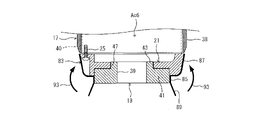
次に、図8の矢印49に示すように、カバー23の被覆部31が間座21側に折り返されることで、カバー23は図5に示した形状となる。これにより、被覆部31が間座21の外周面を覆う。
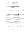
図9に、カバー23の取り付け手順(ロボットの製造方法)の一例を示す。カバー23の取り付けは、ロボットや自動機等により自動で実行されてもよいし、作業者によって手作業で実行されてもよい。
ステップS10では、カバー23の固定部29がフランジ19に取り付けられる(図6参照)。
ステップS20では、フランジ19が複数のボルトにより間座21に固定され、カバー23の固定部29がフランジ19と間座21の間に挟み込んで固定される(図7参照)。
ステップS30では、カバー23の被覆部31が折り返され、被覆部31により間座21の外周面が被覆される(図8参照)。以上により、本フローチャートは終了する。
なお、上述した手順は一例であって、上記手順の少なくとも一部を削除又は変更してもよいし、上記以外の手順を追加してもよい。また、上記手順の少なくとも一部の順番を変更してもよいし、複数の手順が単一の手順にまとめられてもよい。例えば、上述ではフランジ19と間座21とを固定する際に、ボルトがフランジ19側から間座21に向けて挿入される場合について説明したが、ボルトは間座21側からフランジ19に向けて挿入されてもよい。この場合、間座21が手首部17から取り外された状態で、図6及び図7に示すようにカバー23が装着されたフランジ19を間座21に対して固定すればよい。この際、ボルトは間座21側からフランジ19に向けて挿入される。その後、フランジ19が取り付けられた間座21をボルト25により手首部17のアクチュエータAc6に固定し、図8に示すようにカバー23の被覆部31を折り返して間座21の外周面を被覆すればよい。
(1-4.第1実施形態の効果)
以上説明したように、第1実施形態のロボット1は、複数の関節部Jt1~Jt6を備え、先端部にハンドが取り付けられるアーム5と、アーム5に固定され、アーム5の少なくとも一部を覆う、伸縮性を有するカバー23と、を有する。
以上説明したように、第1実施形態のロボット1は、複数の関節部Jt1~Jt6を備え、先端部にハンドが取り付けられるアーム5と、アーム5に固定され、アーム5の少なくとも一部を覆う、伸縮性を有するカバー23と、を有する。
本実施形態によれば、アーム5に例えば間座21の凹部27、ボルト25のヘッド部25a、その他切欠き等による凹凸部がある場合に、カバー23で覆うことにより、凹凸部が外部に露出することを防止できる。これにより、人がロボット1に触れた際に凹凸部で外傷を負うリスクを低減できる。また、カバー23の伸縮性を利用して、アーム5の表面形状に倣わせて隙間を低減しつつ覆うことが可能となり、多種多様な形状に対応できる。また、カバー23が伸縮性を有するため、人がロボット1に当たった際の衝撃力を低減できる。したがって、安全性を向上することができる。
本実施形態において、カバー23は、ゴムを含む材質で構成されてもよい。この場合、ゴム材の弾性を利用して、人がロボット1に当たった際の衝撃力を低減できる。また、ゴム材がアーム5の少なくとも一部の表面を覆うため、凹凸部が露出した場合よりも人に優しい印象を与えることができる。したがって、ロボット1の外観性を向上できる。
本実施形態において、カバー23は、アームに固定される固定部29と、アーム5の少なくとも一部を覆う被覆部31と、を有してもよい。
この場合、カバー23に被覆機能だけでなく、アーム5に固定するための固定機能を持たせることができる。また、カバー23を、固定機能を発揮する部分と被覆機能を発揮する部分とに切り分けることができる。これにより、例えば固定部29の周長を小さくしたり厚みを被覆部31よりも厚くする等により、固定する機能を高めることが可能となる。また、例えば被覆部31の厚みを固定部29よりも薄くする等により、被覆の作業性を向上すること等が可能となる。したがって、カバー23の設計の自由度を向上できる。
本実施形態において、アーム5は、先端部に回転軸Ax6周りに回転可能に配置され、ハンドが取り付けられるフランジ19を有してもよく、その場合には、カバー23はフランジ19に固定されてもよい。
この場合、フランジ19に固定したカバー23により、アーム5のフランジ近傍の部分を覆うことができる。これにより、アーム5のフランジ近傍の部分に例えばボルトヘッドや切欠き等による凹凸部がある場合に、当該凹凸部が外部に露出することを防止できる。これにより、人がロボット1に触れた際に凹凸部で外傷を負うリスクを低減できる。
本実施形態において、アーム5は、ボルト25のヘッド部25aが外表面に露出するように配置された、フランジ19が固定される間座21を有してもよく、その場合には、カバー23は、間座21の外表面を被覆する被覆部31を有してもよい。
この場合、間座21の外表面に配置されたボルト25のヘッド部25aが外部に露出することを防止できる。これにより、人がロボット1に触れた際にボルト25のヘッド部25aや凹部27等による凹凸部で外傷を負うリスクを低減できる。
本実施形態において、アーム5は、関節部Jt6の近傍に配置され、ボルトにより互いに締結されるフランジ19と間座21とを有してもよく、その場合には、固定部29は、フランジ19と間座21に挟まれて固定されてもよい。
この場合、フランジ19と間座21との間をカバー23の固定部29によりシールすることができる。これにより、例えば湿気の侵入や、ロボット1を洗浄する際等における水の侵入を抑制することができ、防水性又は防滴性に優れたロボットを実現できる。
第1実施形態において、複数の関節部Jt1~Jt6を備え、先端部にハンドが取り付けられるアーム5を有するロボット1の製造方法は、固定部29と被覆部31を備え伸縮性を有するカバー23の固定部29をアーム5に固定することと、被覆部31をアーム5側に折り返し、アーム5の少なくとも一部を覆うことと、を有する。
本実施形態によれば、伸縮性を有するカバー23を、固定部29の固定、被覆部31を折り返して被覆、という簡易な手順でロボット1に取り付けることができる。これにより、カバー23の取り付け作業の容易性を向上できる。
(1-5.第1実施形態の変形例>
なお、上述した第1実施形態は、上記に限られるものではなく、その趣旨及び技術的思想を逸脱しない範囲内で種々の変形が可能である。以下、そのような変形例を説明する。
なお、上述した第1実施形態は、上記に限られるものではなく、その趣旨及び技術的思想を逸脱しない範囲内で種々の変形が可能である。以下、そのような変形例を説明する。
(1-5-1.固定方法のバリエーション)
上記の第1実施形態では、カバー23の固定部29をフランジ19と間座21との間に挟むことによりカバー23を固定するようにしたが、カバー23の固定方法はこれに限定されるものではない。例えば、カバーの伸縮性により生じる緊迫力により、固定部をアーム5に対して固定してもよい。
上記の第1実施形態では、カバー23の固定部29をフランジ19と間座21との間に挟むことによりカバー23を固定するようにしたが、カバー23の固定方法はこれに限定されるものではない。例えば、カバーの伸縮性により生じる緊迫力により、固定部をアーム5に対して固定してもよい。
図10は、本変形例に係るカバーを装着した状態のアーム5の先端部の一例を表す図である。図10に示すように、本変形例では、カバー51(図10中グレーの部分。ロボット用カバーの一例)がフランジ19の外周面に固定されると共に、間座21の外周面を被覆する。その結果、間座21の外周面及びフランジ19の外周面は共に、カバー51により被覆されている。カバー51は、アーム5に固定されている。固定構造の詳細については後述する。カバー51は、前述のカバー23と同様に伸縮性を有している。カバー51は、例えばゴムを含む材質で構成されてもよいし、例えば樹脂を含む材質やエラストマーを含む材質で構成されてもよい。
図11は、本変形例に係るカバーの構造の一例を表す斜視図、図12は、間座21を被覆する際のカバーの形状の変化の一例を表す説明図である。図11及び図12に示すように、カバー51は、固定部53と被覆部55とを有する。固定部53と被覆部55は、一体として形成されており、例えば同じ厚みを有するように形成されている。固定部53は、アーム5に固定される部分であり、円筒状に形成されている。固定部53は、被覆部55の底部に形成された開口部57の縁から被覆部55の内側に突出するように形成されている。固定部53は、フランジ19(被固定部材の一例)の外周面を覆うように固定される。固定部53の内周面の周長は、フランジ19の外周面の周長よりも短くなるように形成されている。固定部53の伸縮性により生じる緊迫力により、固定部53がフランジ19の外周面に固定される。
被覆部55(第1被覆部の一例)は、前述の被覆部31と同様に、間座21の外周面を覆う部分である。被覆部55は、間座21の外周面に対応したお椀型の形状に形成されている。図11は、カバー51の初期形状の一例を表しており、被覆部55が固定部53を内側に収容した状態で固定部53がフランジ19の外周面に固定される。図11に示す状態から、図12の矢印59に示すように、被覆部55が固定部53とは反対側に折り返されることで、被覆部55が間座21の外周面を覆う。
なお、カバー51の初期形状は図11に示す形状に限定されるものではなく、例えば図12に示す形状を初期形状としてもよい。この場合、最初に被覆部55を固定部53側に折り返すことで図11に示す形状とし、固定部53をフランジ19に固定し、図12に示すように被覆部55を固定部53とは反対側に折り戻すことで間座21の外周面を被覆すればよい。また、固定部53と被覆部55とを異なる厚みを有するように形成してもよい。例えば、固定部53の厚みを被覆部55よりも厚くする等により、固定する機能を高めることが可能となる。また、例えば被覆部55の厚みを固定部53よりも薄くする等により、被覆部55の柔軟性を高めて被覆の作業性を向上すること等が可能となる。
図13及び図14を参照しつつ、本変形例に係るカバーの取り付け手順の一例について説明する。図13及び図14は、本変形例に係るカバーの取り付け手順の一例を説明するための、アーム5の先端部の断面構造を表す断面図である。なお、図13及び図14において、前述の図6~図8と同様の構成には同符号を付し、適宜説明を省略する。
図13に示すように、カバー51は、図11に示した初期形状の状態で、フランジ19の外周面のうち間座21から露出した部分に、固定部53が緊迫力により固定される。言い換えると、カバー51の固定部53により、アーム5の被覆対象(間座21の外周面)でない部位が被覆される。
次に、図14の矢印61に示すように、カバー51の被覆部55が間座21側に折り返されることで、カバー51は図12に示した形状となり、被覆部55が間座21の外周面を覆う。
本変形例によれば、固定部53の伸縮性により生じる緊迫力により、固定部53をフランジ19の外周面に固定できる。これにより、ボルト等の固定具を使用せずにカバー51を固定できるので、ボルトレスのカバーを実現できる。また、前述の第1実施形態のようにフランジ19を間座21から取り外す必要がないので、カバー51の装着や交換の作業が容易となり、メンテナンス性を向上できる。また、カバー51をフランジ19の側面(回転軸Ax6に垂直な方向に位置する面。外周面ともいう)に固定するので、カバー51がフランジ19に取り付けられるハンドと干渉することを防止できる。
なお、カバー51の固定部53による固定をより強固にするために、例えばフランジ19の外周面に凹部又は凸部を形成してもよい。凹部又は凸部の形状は特に限定されるものではないが、例えば図15に示すように、フランジ19の外周面に一周に亘って膨らんだ形状の凸部63を回転軸Ax6の方向に多段に形成してもよい。なお、凸部63は周方向の複数個所で分離されてもよいし、凸部に加えて又は代えて凹部を形成してもよい。カバー51の固定部53は、凸部63を覆うようにフランジ19の外周面に固定される。
この場合、固定部53の伸縮性により生じる緊迫力に、固定部53と凸部63との間で生じる摩擦力が加わることにより、固定部53をフランジ19の外周面に対してより堅固に固定することができる。
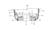
また、カバー51の固定部53による固定をより強固にするために、例えば締付具を使用してもよい。締付具の構成は特に限定されるものではないが、例えば図16に示すように、固定部53の外周に巻き回され、固定部53をフランジ19の外周面に対して締め付ける例えばリング状又はバンド状の締付具65を使用してもよい。
この場合、固定部53の伸縮性により生じる緊迫力に、締付具65による締付力が加わることにより、固定部53をフランジ19の外周面に対してより堅固に固定することができる。
また、締付具による固定をさらに強固にするために、例えばフランジ19の外周面に凹部又は凸部を形成しておき、締付具を凹部又は凸部と係合する係合部を有する構成としてもよい。凹部又は凸部の形状及び締付具の構成は特に限定されるものではないが、例えば図17に示すように、フランジ19の外周面に一周に亘って凹んだ形状の凹部67を形成してもよい。締付具69は、固定部53の外周に巻き回される例えばリング状又はバンド状の締付具であり、凹部67と係合する係合部71を有する。凹部67及び係合部71の少なくとも一方は、周方向の複数個所で分離されてもよい。カバー51の固定部53は、係合した係合部71と凹部67との間に挟まれて固定される。
この場合、固定部53の伸縮性により生じる緊迫力に、締付具69による締付力と、締付具69の係合部71とフランジ19の凹部67との係合により生じる摩擦力が加わることにより、固定部53をフランジ19の外周面に対してさらに堅固に固定することができる。
図18に、本変形例に係るカバー51の取り付け手順(ロボットの製造方法)の一例を示す。カバー51の取り付けは、ロボットや自動機等により自動で実行されてもよいし、作業者によって手作業で実行されてもよい。
ステップS110では、カバー51の固定部53がフランジ19に取り付けられる(図13参照)。なお、フランジ19の外周面に凸部63(凹部でもよい)が形成されている場合には、固定部53は凸部63を覆うようにフランジ19の外周面に固定される(図15参照)。締付具65を使用する場合には、固定部53がフランジ19に取り付けられた後に、締付具65が固定部53の外周に巻き回され、固定部53がフランジ19の外周面に対して締め付けられる(図16参照)。フランジ19の外周面に凹部67(凸部でもよい)を形成し、締付具69の係合部71を凹部67に係合させる場合には、固定部53がフランジ19に取り付けられた後に、係合部71が凹部67に係合するように締付具69が固定部53の外周に巻き回され、固定部53がフランジ19の外周面に対して締め付けられる(図17参照)。
ステップS120では、カバー51の被覆部55が折り返され、被覆部55により間座21の外周面が被覆される(図14参照)。以上により、本フローチャートは終了する。
なお、上述した手順は一例であって、上記手順の少なくとも一部を削除又は変更してもよいし、上記以外の手順を追加してもよい。また、上記手順の少なくとも一部の順番を変更してもよいし、複数の手順が単一の手順にまとめられてもよい。
(1-5-2.ハンドの一部を覆う場合)
上記の第1実施形態では、カバーによりアーム5の一部を覆う場合について説明したが、アーム5の一部に加えてハンドの少なくとも一部を覆うようにしてもよい。
上記の第1実施形態では、カバーによりアーム5の一部を覆う場合について説明したが、アーム5の一部に加えてハンドの少なくとも一部を覆うようにしてもよい。
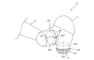
図19は、本変形例に係るカバーを装着した状態のアーム5の先端部及びハンドの基端部の一例を表す図、図20は比較のための参考図であり、カバーを装着していない状態のアーム5の先端部及びハンドの基端部の一例を表す図である。なお、図19及び図20にいて、前述の図2及び図3と同様の構成には同符号を付し、適宜説明を省略する。
図19及び図20に示すように、本変形例では、フランジ19の先端部にハンド73が取り付けられている。ハンド73は、ロボット1が実行する作業や扱うワークに対応したツールであり、エンドエフェクタともいう。ハンド73は、例えばワークを把持可能な複数の指又は爪を有してもよいし、例えばワークを吸着可能な真空パッド又は磁石を有してもよい。例えばワークをすくう作業を行う場合には、ハンド73をヘラ状のハンド等としてもよい。
カバーを装着していない状態を表す図20に示すように、ハンド73は、フランジ19に固定される基部75と、本体部77とを有する。基部75は、複数のボルト79により本体部77に固定されている。ボルト79のヘッド部79aは、基部75の外周面に形成された凹部81に収容されている。基部75の外周面(外表面の一例)には、複数のボルト79のヘッド部79aが露出するように配置されている。間座21の外周面に形成された凹部27にボルト25のヘッド部25aが露出するように収容されている点は、前述の第1実施形態と同様である。ロボット1が作業者と共に稼働する場合、基部75の凹部81、ボルト79のヘッド部79a、間座21の凹部27、ボルト25のヘッド部25a、その他切欠き等の凹凸部が外部に露出することで、作業者がロボット1に触れた際に凹凸部で外傷を負う可能性がある。
本変形例のロボット1では、図19に示すように、カバー83(図19中グレーの部分。ロボット用カバーの一例)が間座21の外周面を被覆すると共に、ハンド73の基部75の外周面を被覆する。基部75の外周面は、ハンド73の少なくとも一部及びハンド73のフランジ側の一部の一例である。カバー83は、アーム5に固定されている。固定構造の詳細については後述する。カバー83は、前述のカバー23,51と同様に伸縮性を有している。カバー83は、例えばゴムを含む材質で構成されてもよいし、例えば樹脂を含む材質やエラストマーを含む材質で構成されてもよい。
図21は、本変形例に係るカバーの構造の一例を表す斜視図である。図21に示すように、カバー83は、固定部85と、第1被覆部87と、第2被覆部89とを有する。固定部85、第1被覆部87、及び第2被覆部89は、一体として形成されており、例えば同じ厚みを有するように形成されている。固定部85は、アーム5に固定される部分であり、円筒状に形成されている。固定部85は、第1被覆部87の底部に形成された開口部91の縁から第2被覆部89側に突出するように形成されている。固定部85は、フランジ19の外周面を覆うように固定される。固定部85の内周面の周長は、フランジ19の外周面の周長よりも短くなるように形成されている。固定部85の伸縮性により生じる緊迫力により、固定部85がフランジ19の外周面に固定される。
第1被覆部87は、前述の被覆部31,55と同様に、間座21の外周面を覆う部分である。第1被覆部87は、固定部85の一方側に形成されており、間座21の外周面に対応したお椀型の形状に形成されている。
第2被覆部89は、ハンド73の基部75の外周面を覆う部分である。第2被覆部89は、固定部85の他方側に形成されており、ハンド73の覆う部分に対応した形状に形成されている。第2被覆部89は、例えばハンド73の基部75の外周面に対応した中空の略円錐台の形状に形成されている。第2被覆部89は、固定部85の第1被覆部87とは反対側の縁から第1被覆部87とは反対側に向けて径を拡大しながら突出するように形成されている。なお、図21は、カバー83の初期形状の一例を表している。
図22~図26を参照しつつ、本変形例に係るカバーの取り付け手順の一例について説明する。図22~図26は、本変形例に係るカバーの取り付け手順の一例を説明するための、アーム5の先端部の断面構造を表す断面図である。なお、図22~図26において、前述の図6~図8、図13及び図14と同様の構成には同符号を付し、適宜説明を省略する。
図22に示すように、カバー83は、図21に示した初期形状の状態から、第1被覆部87が第2被覆部89の外周側(間座21とは反対側)に折り返される。折り返された状態で、カバー83の固定部85は、フランジ19の外周面のうち間座21から露出した部分に緊迫力により固定される。
次に、図23の矢印93に示すように、カバー83の第1被覆部87が間座21側に折り戻されることで、カバー83は図21に示した形状となり、第1被覆部87が間座21の外周面を覆う。
次に、図24の矢印95に示すように、カバー83は、第2被覆部89が第1被覆部87の外周側(間座21側)に折り返される。
次に、図25に示すように、フランジ19の先端部にハンド73が取り付けられる。
次に、図26の矢印97に示すように、カバー83の第2被覆部89がハンド73側に折り戻されることで、カバー83は図21に示した形状となり、第2被覆部89がハンド73の基部75の外周面を覆う。
なお、カバー83の初期形状は図21に示す形状に限定されるものではなく、例えば図22に示す形状を初期形状としてもよい。この場合、第1被覆部87を第2被覆部89の外周側(間座21とは反対側)に折り返す手順が不要となる。また、固定部85と第1被覆部87及び第2被覆部89とを異なる厚みを有するように形成してもよい。例えば、固定部85の厚みを第1被覆部87及び第2被覆部89よりも厚くする等により、固定する機能を高めることが可能となる。また、例えば第1被覆部87及び第2被覆部89の厚みを固定部85よりも薄くする等により、第1被覆部87及び第2被覆部89の柔軟性を高めて被覆の作業性を向上すること等が可能となる。
図27に、本変形例に係るカバー83の取り付け手順(ロボットの製造方法)の一例を示す。カバー83の取り付けは、ロボットや自動機等により自動で実行されてもよいし、作業者によって手作業で実行されてもよい。
ステップS210では、カバー83は、図21に示した初期形状の状態から、第1被覆部87が第2被覆部89の外周側(間座21とは反対側)に折り返される(図22参照)。
ステップS220では、カバー83の固定部85が、フランジ19の外周面のうち間座21から露出した部分に緊迫力により固定される(図22参照)。
ステップS230では、カバー83の第1被覆部87が間座21側に折り戻されることで、間座21の外周面が第1被覆部87により覆われる(図23参照)。
ステップS240では、カバー83の第2被覆部89が第1被覆部87の外周側(間座21側)に折り返される(図24参照)。
ステップS250では、ハンド73がフランジ19の先端部に取り付けられる(図25参照)。
ステップS260では、カバー83の第2被覆部89がハンド73側に折り戻されることで、ハンド73の基部75の外周面が第2被覆部89により覆われる。以上により、本フローチャートは終了する。
なお、上述した手順は一例であって、上記手順の少なくとも一部を削除又は変更してもよいし、上記以外の手順を追加してもよい。また、上記手順の少なくとも一部の順番を変更してもよいし、複数の手順が単一の手順にまとめられてもよい。例えば、カバー83の初期形状が図22に示す形状の場合、第1被覆部87を第2被覆部89の外周側(間座21とは反対側)に折り返すステップS210の手順が不要となる。
本変形例によれば、カバー83がハンド73のフランジ側の一部を被覆する第2被覆部89を有する。これにより、ハンド73のフランジ近傍の部分に例えば凹部81、ボルト79のヘッド部79a、その他切欠き等による凹凸部がある場合に、当該凹凸部が外部に露出することを防止できる。したがって、人がハンド73に触れた際に凹凸部で外傷を負うリスクを低減できる。
本変形例において、カバー83は、フランジ19に固定される固定部85と、固定部85の一方側に形成され、間座21の外周面を被覆する第1被覆部87と、固定部85の他方側に形成され、ハンド73の基部75の外周面を被覆する第2被覆部89と、を有してもよい。
この場合、間座21の外周面を被覆する第1被覆部87と、ハンド73の基部75の外周面を被覆する第2被覆部89との間で、固定部85を共通化できる。これにより、単一のカバー83によって、間座21の外周面と基部75の外周面の両方を被覆することができる。したがって、2つのカバーを使用する場合に比べて、カバーの装着や交換作業の容易化によるメンテナンス性の向上、部品点数の削減による構成の簡素化、コストの削減等を図ることができる。
なお、上記の変形例では、カバー83によりアーム5の間座21とハンド73の基部75の両方を覆う場合について説明したが、フランジ19に固定されたカバーによりハンド73の基部75のみを覆うようにしてもよい。この場合、図28及び図29に示すように、固定部85と第2被覆部89とを有するカバー99の固定部85をフランジ19に固定し、第2被覆部89によりハンド73の基部75を被覆してもよい。
<2.第2実施形態>
第2実施形態は、ロボットのアームの先端部以外の関節部にカバーを取り付ける場合の実施形態である。第2実施形態では、一例として関節部Jt5にカバーを取り付ける場合について説明するが、他の関節部Jt1~Jt4に同様の構成のカバーを取り付けてもよい。
第2実施形態は、ロボットのアームの先端部以外の関節部にカバーを取り付ける場合の実施形態である。第2実施形態では、一例として関節部Jt5にカバーを取り付ける場合について説明するが、他の関節部Jt1~Jt4に同様の構成のカバーを取り付けてもよい。
(2-1.カバーの取り付け箇所)
図30~図32を参照しつつ、第2実施形態に係るカバーの取り付け箇所の一例について説明する。図30は、カバーを装着した状態のアーム5の関節部Jt5の一例を表す図、図31は比較のための参考図であり、カバーを装着していない状態のアーム5の関節部Jt5の一例を表す図である。図32は、アーム5の関節部Jt5近傍の断面構造の一例を破断線により表す部分断面図である。
図30~図32を参照しつつ、第2実施形態に係るカバーの取り付け箇所の一例について説明する。図30は、カバーを装着した状態のアーム5の関節部Jt5の一例を表す図、図31は比較のための参考図であり、カバーを装着していない状態のアーム5の関節部Jt5の一例を表す図である。図32は、アーム5の関節部Jt5近傍の断面構造の一例を破断線により表す部分断面図である。
図30及び図31に示すように、手首部17は、上腕部15との間の関節部Jt5に設けられたアクチュエータAc5の駆動により、上腕部15の先端側に対し、回転軸Ax5周りに旋回駆動される。カバーを装着していない状態を表す図31に示すように、上腕部15の関節部Jt5の近傍部位には位置決め用の溝101が形成されており、手首部17の関節部Jt5の近傍部位には位置決め用の溝103が形成されている。溝101,103は、例えば回転軸Ax5に平行な直線状の溝として形成されている。溝101,103は、手首部17が上腕部15に対して相対的に回転することにより、回転軸Ax5周りの周方向に相対的に移動する。溝101,103が一致する周方向の位置(回転角度)が、アクチュエータAc5の回転角度の原点として例えばロボットコントローラ(図示省略)に記憶される。当該原点は、例えばロボット1の据え付け時に使用される。ロボット1が作業者と共に稼働する場合、溝101,103等の凹凸部が外部に露出することで、作業者がロボット1に触れた際に凹凸部で外傷を負う可能性がある。
本実施形態のロボット1では、図30に示すように、カバー105(ロボット用カバーの一例)が上腕部15の関節部Jt5の近傍部位の外周面を被覆すると共に、カバー107(ロボット用カバーの一例)が手首部17の関節部Jt5の近傍部位の外周面を被覆する。上腕部15の関節部Jt5の近傍部位及び手首部17の関節部Jt5の近傍部位は、アーム5の少なくとも一部の一例である。カバー105,107は、アーム5に固定されている。例えば図32に示すように、カバー105は上腕部15の筐体部材109に固定され、カバー107は手首部17の第1筐体部材111及び第2筐体部材113に挟まれて固定される。
カバー105,107は、伸縮性を有している。カバー105,107は、例えばゴムを含む材質で構成されてもよいし、例えば樹脂を含む材質やエラストマーを含む材質で構成されてもよい。上腕部15の関節部Jt5の近傍部位の外周面、及び、手首部17の関節部Jt5の近傍部位の外周面をそれぞれカバー105,107で覆うことにより、溝101,103等の凹凸部が外部に露出することを防止でき、作業者がロボット1に触れた際に外傷を負うリスクを低減できる。また、カバー105,107の伸縮性を利用して、アーム5の表面形状に倣わせて隙間を低減しつつ覆うことが可能となり、多種多様な形状に対応できる。また、カバー105,107が伸縮性を有するため、人がロボット1に当たった際の衝撃力を低減できる。
なお、上記溝101,103に加えて又は代えて、前述の第1実施形態と同様に、関節部Jt5の近傍にボルトヘッドを収容する凹部等が形成されていてもよい。
(2-2.カバーの構成、取り付け手順)
図33~図39を参照しつつ、第2実施形態に係るカバーの構成の一例及びカバーの取り付け手順の一例について説明する。図33は、手首部17に装着されるカバー107の構造の一例を表す斜視図、図34及び図35は、手首部17に装着されるカバー107の取り付け手順の一例を説明するための、手首部17の関節部Jt5近傍の断面構造の一例を破断線により表す部分断面図である。図36及び図37は、上腕部15に装着されるカバー105の構造の一例を表す斜視図、図38及び図39は、上腕部15に装着されるカバー105の取り付け手順の一例を説明するための、上腕部15の関節部Jt5近傍の断面構造の一例を破断線により表す部分断面図である。
図33~図39を参照しつつ、第2実施形態に係るカバーの構成の一例及びカバーの取り付け手順の一例について説明する。図33は、手首部17に装着されるカバー107の構造の一例を表す斜視図、図34及び図35は、手首部17に装着されるカバー107の取り付け手順の一例を説明するための、手首部17の関節部Jt5近傍の断面構造の一例を破断線により表す部分断面図である。図36及び図37は、上腕部15に装着されるカバー105の構造の一例を表す斜視図、図38及び図39は、上腕部15に装着されるカバー105の取り付け手順の一例を説明するための、上腕部15の関節部Jt5近傍の断面構造の一例を破断線により表す部分断面図である。
図33に示すように、カバー107は、円環状の固定部115と、円筒状の被覆部117とを有する。固定部115と被覆部117は、一体として形成されており、例えば同じ厚みを有するように形成されている。固定部115は、アーム5に固定される部分である。固定部115は、被覆部117の先端部の縁から内周側に延びるように形成されている。固定部115は、手首部17の第1筐体部材111と第2筐体部材113に挟まれて固定される。
被覆部117は、第2筐体部材113の外周面を覆う部分である。被覆部117は、アーム5の覆う部分に対応した形状に形成されている。被覆部117は、例えば第2筐体部材113の外周面に対応した円筒形状に形成されている。図33は、カバー107の初期形状の一例を表しており、この状態で固定部115が手首部17に固定される。
図34に示すように、第2筐体部材113が第1筐体部材111から取り外される。カバー107は、図33に示した初期形状の状態で、被覆部117が第2筐体部材113の外周面に取り付けられ、固定部115が第2筐体部材113の第1筐体部材111側の端面に取り付けられる。この際、被覆部117の周長を、第2筐体部材113の外周面の周長よりも若干短い周長としておき、被覆部117の伸縮性により生じる緊迫力により、被覆部117を第2筐体部材113に仮固定してもよい。
次に、図35に示すように、第2筐体部材113が第1筐体部材111に取り付けられる。第2筐体部材113(第1の被固定部材の一例)と第1筐体部材111(第2の被固定部材の一例)とは、複数のボルト(第2の締結具の一例。図示省略)により互いに締結される。ボルトは、第2筐体部材113側から第1筐体部材111に向けて挿入されてもよいし、第1筐体部材111側から第2筐体部材113に向けて挿入されてもよい。ボルトが第1筐体部材111側から挿入される場合には、手首部17の内部から作業可能なように所定の部品が取り外される。カバー107の固定部115は、第1筐体部材111と第2筐体部材113に挟まれて固定される。被覆部117は、第2筐体部材113の外周面を被覆する。
なお、カバー107の取り付け手順は上記に限定されるものではない。例えば、カバー107を第1筐体部材111に仮固定しておき、第2筐体部材113を第1筐体部材111に取り付けた後に、カバー107の被覆部117を第2筐体部材113側に折り返して第2筐体部材113の外周面を被覆してもよい。また、固定部115と被覆部117とを異なる厚みを有するように形成してもよい。例えば、固定部115の厚みを被覆部117よりも厚くする等により、固定する機能を高めることが可能となる。また、例えば被覆部117の厚みを固定部115よりも薄くする等により、被覆部117の柔軟性を高めて被覆の作業性を向上すること等が可能となる。
図36に示すように、カバー105は、円筒状の固定部119と、固定部119よりも大径の円筒状の被覆部121と、固定部119の端部と被覆部121の端部を連結する円環状の連結部123とを有する。固定部119、被覆部121、及び連結部123は、一体として形成されており、例えば同じ厚みを有するように形成されている。連結部123は、被覆部121の先端部の縁から内周側に延びるように形成されている。連結部123の径方向の幅は、上腕部15の筐体部材109の厚みと略同一となるように形成されている。固定部119は、アーム5に固定される部分である。固定部119は、連結部123に形成された開口部125の縁から被覆部121の外側に突出するように形成されている。
被覆部121は、上腕部15の筐体部材109の関節部Jt5の近傍部位の外周面を覆う部分である。被覆部121は、アーム5の覆う部分に対応した形状に形成されている。被覆部121は、例えば筐体部材109の外周面に対応した円筒形状に形成されている。図36は、カバー105の初期形状の一例を表しており、この状態で被覆部121が筐体部材109の外周面に取り付けられる。被覆部121の周長は、筐体部材109の外周面の周長よりも短い周長となっており、被覆部121の伸縮性により生じる緊迫力により筐体部材109の外周面に固定される。被覆部121は固定部としても機能する。図36に示す状態から、図37の矢印127に示すように、固定部119が被覆部121の内側に収容されるように折り返されることで、固定部119が筐体部材109の内周面を覆う。これにより、被覆部121と固定部119とが筐体部材109の端部を両側から挟み、カバー105が筐体部材109の端部に固定される。
図38に示すように、カバー105は、図36に示した初期形状の状態で、被覆部121が筐体部材109の外周面に緊迫力により取り付けられ、連結部123が筐体部材109の関節部Jt5側の端面に取り付けられる。
次に、図39の矢印129に示すように、カバー105の固定部119が筐体部材109の内側に折り返されることで、カバー105は図37に示した形状となる。これにより、カバー105が筐体部材109の端部に固定されると共に、被覆部121が筐体部材109の端部の外周面を覆う。
なお、カバー105の固定部119をなくし、カバー105が被覆部121と連結部123のみを有する構成としてもよい。この場合、被覆部121が固定部としても機能し、固定部を兼ねる。また、前述の図15と同様に、カバー105の固定をより強固にするために、例えば筐体部材109の外周面に凹部又は凸部を形成してもよい。また、前述の図16と同様に、カバー105の被覆部121の外周に巻き回され、被覆部121を筐体部材109の外周面に対して締め付ける締付具を使用してもよい。また、前述の図17と同様に、締付具は筐体部材109の外周面に形成された凹部又は凸部と係合する係合部を有してもよい。
(2-3.第2実施形態の効果)
以上説明した第2実施形態によれば、アーム5の関節部Jt1~Jt5に例えば位置決め用の溝101,103等による凹凸部がある場合に、カバー105,107で覆うことにより、凹凸部が外部に露出することを防止できる。これにより、人がロボット1に触れた際に凹凸部で外傷を負うリスクを低減できる。また、カバー105,107の伸縮性を利用して、アーム5の表面形状に倣わせて隙間を低減しつつ覆うことが可能となり、多種多様な形状に対応できる。また、カバー105,107が伸縮性を有するため、人がロボット1に当たった際の衝撃力を低減できる。したがって、安全性を向上することができる。
以上説明した第2実施形態によれば、アーム5の関節部Jt1~Jt5に例えば位置決め用の溝101,103等による凹凸部がある場合に、カバー105,107で覆うことにより、凹凸部が外部に露出することを防止できる。これにより、人がロボット1に触れた際に凹凸部で外傷を負うリスクを低減できる。また、カバー105,107の伸縮性を利用して、アーム5の表面形状に倣わせて隙間を低減しつつ覆うことが可能となり、多種多様な形状に対応できる。また、カバー105,107が伸縮性を有するため、人がロボット1に当たった際の衝撃力を低減できる。したがって、安全性を向上することができる。
また第2実施形態において、関節部Jt5に装着するカバーを2つのカバー105,107として構成することで、互いに相対回転する上腕部15の溝101と手首部17の溝103の両方を、関節部Jt5の駆動を阻害することなく覆うことができる。
(2-4.第2実施形態の変形例>
なお、上述した第2実施形態は、上記に限られるものではなく、その趣旨及び技術的思想を逸脱しない範囲内で種々の変形が可能である。例えば、上記の第2実施形態では、関節部Jt5に装着するカバーを2つのカバーで構成したが、カバーを単一の構成としてもよい。
なお、上述した第2実施形態は、上記に限られるものではなく、その趣旨及び技術的思想を逸脱しない範囲内で種々の変形が可能である。例えば、上記の第2実施形態では、関節部Jt5に装着するカバーを2つのカバーで構成したが、カバーを単一の構成としてもよい。
図40は、本変形例に係るカバーを装着した状態のアーム5の関節部Jt5の一例を表す図、図41は、本変形例に係るカバーの構造の一例を表す斜視図、図42は、アーム5の関節部Jt5近傍の断面構造の一例を破断線により表す部分断面図である。
本変形例のロボット1では、図40に示すように、単一構成であるカバー131(ロボット用カバーの一例)が上腕部15の関節部Jt5の近傍部位の外周面、及び、手首部17の関節部Jt5の近傍部位の外周面の両方を被覆する。カバー131は、アーム5に固定されている。カバー131は、伸縮性を有している。カバー131は、例えばゴムを含む材質で構成されてもよいし、例えば樹脂を含む材質やエラストマーを含む材質で構成されてもよい。
図41に示すように、カバー131は、円環状の固定部133と、円筒状の被覆部135とを有する。固定部133と被覆部135は、一体として形成されており、例えば同じ厚みを有するように形成されている。固定部133は、アーム5に固定される部分である。固定部133は、被覆部135の先端部の縁から内周側に延びるように形成されている。固定部133は、手首部17の第1筐体部材111と第2筐体部材113に挟まれて固定される。
被覆部135は、上腕部15の端部の外周面及び手首部17の端部の外周面を覆う部分である。被覆部135は、アーム5の覆う部分に対応した形状に形成されている。被覆部135は、例えば上腕部15の端部の外周面及び手首部17の端部の外周面に対応した円筒形状に形成されている。図41は、カバー131の初期形状の一例を表しており、この状態で固定部133が手首部17に固定される。
図42に示すように、カバー131は、固定部133が手首部17の第1筐体部材111及び第2筐体部材113に挟まれることで、手首部17に固定される。カバー131は、手首部17の第2筐体部材113の外周面については密着して被覆するが、上腕部15の筐体部材109の外周面についてはクリアランスを介して被覆する。
本変形例によれば、上腕部15の関節部Jt5の近傍部位及び手首部17の関節部Jt5の近傍部位の外周面をカバー131でそれぞれ覆うことにより、溝101,103等の凹凸部が外部に露出することを防止でき、作業者がロボット1に触れた際に外傷を負うリスクを低減できる。また、カバー131は、関節部Jt5の一方の部位(手首部17)に固定されると共に、他方の部位(上腕部15)に対してクリアランスを設けられる。これにより、互いに相対回転する上腕部15の溝101と手首部17の溝103の両方を、単一のカバー131によって関節部Jt5の駆動を阻害することなく覆うことができる。したがって、2つのカバーを使用する場合に比べて、カバーの装着や交換作業の容易化によるメンテナンス性の向上、部品点数の削減による構成の簡素化、コストの削減等を図ることができる。
以上において、上述した第1及び第2実施形態が解決しようとする課題や、第1及び第2実施形態の効果は、前記した内容に限定されるものではない。すなわち、上述した第1及び第2実施形態によって、上述されていない課題を解決したり、上述されていない効果を奏することもでき、また、記載されている課題の一部のみを解決したり、記載されている効果の一部のみを奏することがある。
なお、以上の説明において、「垂直」「平行」「平面」等の記載がある場合には、当該記載は厳密な意味ではない。すなわち、それら「垂直」「平行」「平面」とは、設計上、製造上の公差、誤差が許容され、「実質的に垂直」「実質的に平行」「実質的に平面」という意味である。
また、以上の説明において、外観上の寸法や大きさ、形状、位置等が「同一」「同じ」「等しい」「異なる」等の記載がある場合は、当該記載は厳密な意味ではない。すなわち、それら「同一」「同じ」「等しい」「異なる」とは、設計上、製造上の公差、誤差が許容され、「実質的に同一」「実質的に同じ」「実質的に等しい」「実質的に異なる」という意味である。
また、以上既に述べた以外にも、上記実施形態や各変形例による手法を適宜組み合わせて利用しても良い。その他、一々例示はしないが、上記実施形態や各変形例は、その趣旨を逸脱しない範囲内において、種々の変更が加えられて実施されるものである。
1 ロボット
5 アーム
19 フランジ(被固定部材、第1の被固定部材)
21 間座(台座、第2の被固定部材)
23 カバー(ロボット用カバー)
25 ボルト(第1の締結具)
29 固定部
31 被覆部(第1被覆部)
51 カバー(ロボット用カバー)
53 固定部
55 被覆部(第1被覆部)
63 凸部
65 締付具
67 凹部
69 締付具
71 係合部
73 ハンド
75 基部(フランジ側の一部)
83 カバー(ロボット用カバー)
85 固定部
87 第1被覆部
89 第2被覆部
99 カバー(ロボット用カバー)
105 カバー(ロボット用カバー)
107 カバー(ロボット用カバー)
115 固定部
117 被覆部
119 固定部
121 被覆部
131 カバー(ロボット用カバー)
Jt1~Jt6 関節部
5 アーム
19 フランジ(被固定部材、第1の被固定部材)
21 間座(台座、第2の被固定部材)
23 カバー(ロボット用カバー)
25 ボルト(第1の締結具)
29 固定部
31 被覆部(第1被覆部)
51 カバー(ロボット用カバー)
53 固定部
55 被覆部(第1被覆部)
63 凸部
65 締付具
67 凹部
69 締付具
71 係合部
73 ハンド
75 基部(フランジ側の一部)
83 カバー(ロボット用カバー)
85 固定部
87 第1被覆部
89 第2被覆部
99 カバー(ロボット用カバー)
105 カバー(ロボット用カバー)
107 カバー(ロボット用カバー)
115 固定部
117 被覆部
119 固定部
121 被覆部
131 カバー(ロボット用カバー)
Jt1~Jt6 関節部
Claims (14)
- 複数の関節部を備え、先端部にハンドが取り付けられるアームと、
前記アームに固定され、前記アーム及び前記ハンドの少なくとも一方の少なくとも一部を覆う、伸縮性を有するカバーと、
を有する、ロボット。 - 前記カバーは、
ゴムを含む材質で構成されている、
請求項1に記載のロボット。 - 前記カバーは、
前記アームに固定される固定部と、
前記アーム及び前記ハンドの少なくとも一方の少なくとも一部を覆う被覆部と、を有する、
請求項1又は2に記載のロボット。 - 前記アームは、
前記先端部に回転軸周りに回転可能に配置され、前記ハンドが取り付けられるフランジを有し、
前記カバーは、
前記フランジに固定される、
請求項1~3のいずれか1項に記載のロボット。 - 前記アームは、
第1の締結具が外表面に露出するように配置され、前記フランジが固定される台座を有し、
前記カバーは、
前記台座の前記外表面を被覆する第1被覆部を有する、
請求項4に記載のロボット。 - 前記カバーは、
前記ハンドの前記フランジ側の一部を被覆する第2被覆部を有する、
請求項4又は5に記載のロボット。 - 前記アームは、
第1の締結具が外表面に露出するように配置され、前記フランジが固定される台座を有し、
前記カバーは、
前記フランジに固定される固定部と、
前記固定部の一方側に形成され、前記台座の前記外表面を被覆する第1被覆部と、
前記固定部の他方側に形成され、前記ハンドの前記フランジ側の一部を被覆する第2被覆部と、
を有する、
請求項4に記載のロボット。 - 前記アームは、
前記関節部に配置され、第2の締結具により互いに締結される第1の被固定部材と第2の被固定部材とを有し、
前記固定部は、
前記第1の被固定部材と前記第2の被固定部材に挟まれて固定される、
請求項3に記載のロボット。 - 前記アームは、
前記関節部に配置された被固定部材を有し、
前記固定部は、
前記被固定部材の外周面を覆うように固定されており、当該外周面よりも短い周長を有する、
請求項3に記載のロボット。 - 前記被固定部材は、
前記外周面に凹部又は凸部を有し、
前記固定部は、
前記凹部又は前記凸部を覆うように前記被固定部材の前記外周面に固定される、
請求項9に記載のロボット。 - 前記固定部の外周に巻き回され、前記固定部を前記被固定部材の前記外周面に対して締め付ける締付具をさらに有する、
請求項9又は10に記載のロボット。 - 前記被固定部材は、
前記外周面に凹部又は凸部を有し、
前記締付具は、
前記凹部又は前記凸部と係合する係合部を有する、
請求項11に記載のロボット。 - 複数の関節部を備え、先端部にハンドが取り付けられるアームを有するロボットに取り付けられるロボット用カバーであって、
伸縮性を有し、
前記アームに固定される固定部と、
前記アーム及び前記ハンドの少なくとも一方の少なくとも一部を覆う被覆部と、
を有する、
ロボット用カバー。 - 複数の関節部を備え、先端部にハンドが取り付けられるアームを有するロボットの製造方法であって、
固定部と被覆部を備え伸縮性を有するカバーの前記固定部を前記アームに固定することと、
前記被覆部を前記アーム側又は前記ハンド側に折り返し、前記アーム及び前記ハンドの少なくとも一方の少なくとも一部を覆うことと、
を有する、
ロボットの製造方法。
Priority Applications (2)
| Application Number | Priority Date | Filing Date | Title |
|---|---|---|---|
| JP2023520647A JP7538956B2 (ja) | 2021-05-11 | 2021-05-11 | ロボット、ロボット用カバー、ロボットの製造方法 |
| PCT/JP2021/017958 WO2022239135A1 (ja) | 2021-05-11 | 2021-05-11 | ロボット、ロボット用カバー、ロボットの製造方法 |
Applications Claiming Priority (1)
| Application Number | Priority Date | Filing Date | Title |
|---|---|---|---|
| PCT/JP2021/017958 WO2022239135A1 (ja) | 2021-05-11 | 2021-05-11 | ロボット、ロボット用カバー、ロボットの製造方法 |
Publications (1)
| Publication Number | Publication Date |
|---|---|
| WO2022239135A1 true WO2022239135A1 (ja) | 2022-11-17 |
Family
ID=84028973
Family Applications (1)
| Application Number | Title | Priority Date | Filing Date |
|---|---|---|---|
| PCT/JP2021/017958 Ceased WO2022239135A1 (ja) | 2021-05-11 | 2021-05-11 | ロボット、ロボット用カバー、ロボットの製造方法 |
Country Status (2)
| Country | Link |
|---|---|
| JP (1) | JP7538956B2 (ja) |
| WO (1) | WO2022239135A1 (ja) |
Citations (4)
| Publication number | Priority date | Publication date | Assignee | Title |
|---|---|---|---|---|
| JPH0283192A (ja) * | 1988-09-20 | 1990-03-23 | Tokico Ltd | 工業用ロボット |
| JP2009056558A (ja) * | 2007-08-31 | 2009-03-19 | Toshiba Corp | マニピュレータ |
| JP2017209758A (ja) * | 2016-05-26 | 2017-11-30 | ファナック株式会社 | 衝撃緩和部材を有するツールを備えたロボット |
| JP2018024070A (ja) * | 2016-08-12 | 2018-02-15 | 川崎重工業株式会社 | アイソレータシステム |
-
2021
- 2021-05-11 WO PCT/JP2021/017958 patent/WO2022239135A1/ja not_active Ceased
- 2021-05-11 JP JP2023520647A patent/JP7538956B2/ja active Active
Patent Citations (4)
| Publication number | Priority date | Publication date | Assignee | Title |
|---|---|---|---|---|
| JPH0283192A (ja) * | 1988-09-20 | 1990-03-23 | Tokico Ltd | 工業用ロボット |
| JP2009056558A (ja) * | 2007-08-31 | 2009-03-19 | Toshiba Corp | マニピュレータ |
| JP2017209758A (ja) * | 2016-05-26 | 2017-11-30 | ファナック株式会社 | 衝撃緩和部材を有するツールを備えたロボット |
| JP2018024070A (ja) * | 2016-08-12 | 2018-02-15 | 川崎重工業株式会社 | アイソレータシステム |
Also Published As
| Publication number | Publication date |
|---|---|
| JPWO2022239135A1 (ja) | 2022-11-17 |
| JP7538956B2 (ja) | 2024-08-22 |
Similar Documents
| Publication | Publication Date | Title |
|---|---|---|
| US9073218B2 (en) | Multiple joints robot having cover on end effector attachment | |
| US20190047159A1 (en) | Work device and dual-arm work device | |
| US20120103125A1 (en) | Robot arm assembly | |
| JP6538279B2 (ja) | ストッパ装置、回転関節、およびロボット | |
| JP6595539B2 (ja) | ロボットおよびパラレルリンクロボット | |
| US10744637B2 (en) | Robot | |
| JP6736679B2 (ja) | 減速機付きモータ及び多関節ロボット | |
| US20200338760A1 (en) | Boot seal, robot, and parallel link robot | |
| KR101012053B1 (ko) | 서비스 로봇용 6축 아암 장치 | |
| WO2022239135A1 (ja) | ロボット、ロボット用カバー、ロボットの製造方法 | |
| WO2020206685A1 (zh) | 限位装置、机械臂及机器人 | |
| US11548172B2 (en) | Robot | |
| JPH11254377A (ja) | ロボット | |
| EP4559638A1 (en) | Robot and method for manufacturing robot | |
| KR101914648B1 (ko) | 산업용 로봇의 케이블 가이드의 디스트리뷰터 | |
| JP2017087374A (ja) | ロボットのハンド接続構造 | |
| CN210336012U (zh) | 限位装置、机械臂及机器人 | |
| US20240269825A1 (en) | Parallel link mechanism and link operation device | |
| US20230381980A1 (en) | Articulated robot | |
| JPH07328983A (ja) | 産業用ロボットのケーブル処理装置 | |
| JP7594102B2 (ja) | 手首用カバー、ロボットおよび手首用カバーセット | |
| TWI917626B (zh) | 手腕用外殼、機器人以及手腕用外殼組 | |
| JP7453419B2 (ja) | 絶縁カバー、ブラケット、ロボット、溶接装置およびロボットシステム | |
| JP2001038671A (ja) | 多関節型ロボット | |
| JP2024102443A (ja) | 自在継手 |
Legal Events
| Date | Code | Title | Description |
|---|---|---|---|
| 121 | Ep: the epo has been informed by wipo that ep was designated in this application |
Ref document number: 21941869 Country of ref document: EP Kind code of ref document: A1 |
|
| WWE | Wipo information: entry into national phase |
Ref document number: 2023520647 Country of ref document: JP |
|
| NENP | Non-entry into the national phase |
Ref country code: DE |
|
| 122 | Ep: pct application non-entry in european phase |
Ref document number: 21941869 Country of ref document: EP Kind code of ref document: A1 |