WO2022224328A1 - 操作入力装置、情報処理装置および操作入力方法 - Google Patents
操作入力装置、情報処理装置および操作入力方法 Download PDFInfo
- Publication number
- WO2022224328A1 WO2022224328A1 PCT/JP2021/015938 JP2021015938W WO2022224328A1 WO 2022224328 A1 WO2022224328 A1 WO 2022224328A1 JP 2021015938 W JP2021015938 W JP 2021015938W WO 2022224328 A1 WO2022224328 A1 WO 2022224328A1
- Authority
- WO
- WIPO (PCT)
- Prior art keywords
- operation knob
- knob
- display
- information
- bending
- Prior art date
- Legal status (The legal status is an assumption and is not a legal conclusion. Google has not performed a legal analysis and makes no representation as to the accuracy of the status listed.)
- Ceased
Links
Images


Classifications
-
- G—PHYSICS
- G06—COMPUTING OR CALCULATING; COUNTING
- G06F—ELECTRIC DIGITAL DATA PROCESSING
- G06F3/00—Input arrangements for transferring data to be processed into a form capable of being handled by the computer; Output arrangements for transferring data from processing unit to output unit, e.g. interface arrangements
- G06F3/01—Input arrangements or combined input and output arrangements for interaction between user and computer
- G06F3/03—Arrangements for converting the position or the displacement of a member into a coded form
- G06F3/033—Pointing devices displaced or positioned by the user, e.g. mice, trackballs, pens or joysticks; Accessories therefor
- G06F3/0362—Pointing devices displaced or positioned by the user, e.g. mice, trackballs, pens or joysticks; Accessories therefor with detection of one-dimensional [1D] translations or rotations of an operating part of the device, e.g. scroll wheels, sliders, knobs, rollers or belts
-
- G—PHYSICS
- G06—COMPUTING OR CALCULATING; COUNTING
- G06F—ELECTRIC DIGITAL DATA PROCESSING
- G06F3/00—Input arrangements for transferring data to be processed into a form capable of being handled by the computer; Output arrangements for transferring data from processing unit to output unit, e.g. interface arrangements
- G06F3/01—Input arrangements or combined input and output arrangements for interaction between user and computer
- G06F3/03—Arrangements for converting the position or the displacement of a member into a coded form
- G06F3/041—Digitisers, e.g. for touch screens or touch pads, characterised by the transducing means
Definitions
- the present disclosure relates to an operation input device, an information processing device, and an operation input method.
- Patent Literature 1 describes an operation input device that includes an operator, which is a dial switch or a rotary switch, and a finger sensor that detects the number of fingers holding the operator.
- the operation input device identifies the number of fingers gripping the operator based on the detection result of the finger sensor, and switches the operation command for the operation input according to the number of fingers gripping the operator.
- the operation input device described in Patent Document 1 has the problem of poor operability because it is necessary to change the number of fingers that hold the operator when switching to another operation. For example, even if the manipulator is easier to rotate with a larger number of fingers, it may be necessary to unnaturally rotate the manipulator with a smaller number of fingers depending on the function to be executed. Further, if the finger touches the manipulator while rotating the manipulator, a function different from the function to be executed may be erroneously executed.
- the present disclosure is intended to solve the above problems, and provides an operation input device, an information processing device, and an operation input method that enable an operation corresponding to a desired function to be performed regardless of the number of fingers that hold the operator. for the purpose.
- An operation input device includes an operation knob provided rotatably on a touch surface of a touch panel and an operation element having a detection unit that detects an operation of grasping and bending the operation knob, and an operation element.
- an operation information generation unit that generates operation information indicating an operation and outputs the operation information to a function execution unit that executes a function corresponding to the operation, the operation information generation unit bending the operation knob detected by the detection unit; Generates operation information indicating the operation to be performed.
- an operator having an operation knob and a detection unit, an operation information generator that generates operation information indicating an operation using the operator, and outputs the operation information to a function execution unit, the operation information
- the generation unit generates operation information indicating an operation to bend the operation knob detected by the detection unit. Since the function to be executed can be specified by a natural operation of bending the operation knob by changing the gripping force, the operation input device according to the present disclosure can perform the desired function regardless of the number of fingers gripping the operation element. Corresponding operations can be performed.
- FIG. 1 is a block diagram showing a configuration example of an information processing apparatus according to Embodiment 1;
- FIG. FIG. 2A is a perspective view showing the manipulator, and
- FIG. 2B is a configuration diagram showing the internal configuration of the manipulator.
- FIG. 3A is a configuration diagram showing the internal configuration of the manipulator before an operation to bend the operation knob by holding it, and
- 5A is a block diagram showing a hardware configuration that implements the functions of the operation input device according to Embodiment 1, and
- FIG. 5B shows a hardware configuration that implements the functions of the operation input device according to Embodiment 1.
- FIG. 1 is a block diagram showing a configuration example of an information processing apparatus according to Embodiment 1;
- FIG. FIG. 2A is a perspective view showing the manipulator, and
- FIG. 2B is a configuration diagram showing the
- FIG. 3 is a block diagram showing a hardware configuration
- FIG. FIG. 9 is a front view showing a configuration example of an operation input device according to Embodiment 2
- 9 is a flowchart showing an operation input method according to Embodiment 2
- FIG. 10 is a screen diagram showing a display example when performing a process of selecting target item information from a plurality of items of item information by an operation combining the operation of sliding the operation knob and the operation of bending the operation knob.
- FIG. 10 is a screen diagram showing a display example when processing for enlarging or reducing an overhead view image of a vehicle is performed by an operation combining a sliding operation of an operation knob and an operation of bending the operation knob;
- FIG. 10 is a screen diagram showing a display example when processing for enlarging or reducing an overhead view image of a vehicle is performed by an operation combining a sliding operation of an operation knob and an operation of bending the operation knob;
- FIG. 9 is a front view showing a configuration example of
- FIG. 10 is a screen diagram showing a display example when a process of sliding the bird's-eye view image of the vehicle left and right is performed by an operation combining the operation of sliding the operation knob and the operation of bending the operation knob.
- FIG. 11 is a screen diagram showing a display example when CD playback processing is performed by a combination of an operation of sliding the operation knob and an operation of bending the operation knob.
- FIG. 10 is a screen diagram showing a display example when performing a process of sliding the center coordinates of the map around the vehicle by an operation combining the operation of sliding the operation knob and the operation of bending the operation knob.
- FIG. 13A is a screen diagram showing a display example when the process of displaying the scenery after the vehicle has passed on the travel route of the vehicle is performed by an operation combining the operation of sliding the operation knob and the operation of bending the operation knob.
- FIG. 13B is a screen diagram showing a display example when the process of displaying the scenery before the vehicle passes on the travel route of the vehicle is performed by an operation combining the operation of sliding the operation knob and the operation of bending the operation knob. be.
- FIG. 8 is a screen diagram showing a display example when a process of displaying a guide line for reversing in an image behind the vehicle is performed by an operation combining a sliding operation of the operation knob and an operation of bending the operation knob.
- FIG. 10 is a screen diagram showing a display example when a process of displaying an obstacle warning image on a bird's-eye view image of a vehicle is performed by an operation combining a sliding operation of the operation knob and an operation of bending the operation knob.
- FIG. 10 is a screen diagram showing a display example when a process of controlling an imaging direction of an imaging unit that images a person is performed by an operation combining a sliding operation of an operation knob and an operation of bending the operation knob.
- FIG. 10 is a screen diagram showing a display example when processing is performed to control the imaging direction of an imaging unit that captures a bird's-eye view image of a vehicle by an operation combining the operation of sliding the operation knob and the operation of bending the operation knob.
- FIG. 10 is a screen diagram showing a display example when a process of displaying an obstacle warning image on a bird's-eye view image of a vehicle is performed by an operation combining a sliding operation of the operation knob and an operation of bending the operation knob.
- FIG. 11 is a screen diagram showing a display example when a process of transitioning a plurality of types of processing screens is performed by an operation combining a sliding operation of the operation knob and an operation of bending the operation knob;
- FIG. 10 is a screen diagram showing a display example (1) when a process of selecting item information from a menu list is performed by an operation combining a sliding operation of the operation knob and an operation of bending the operation knob;
- FIG. 10 is a screen diagram showing a display example (2) when a process of selecting item information from a menu list is performed by an operation combining the operation of sliding the operation knob and the operation of bending the operation knob;
- FIG. 10 is a screen diagram showing a display example (1) when a process of selecting item information from a menu list is performed by an operation combining a sliding operation of the operation knob and an operation of bending the operation knob;
- FIG. 10 is a screen diagram showing a display example (2) when a process of selecting item information from a menu list is performed by an operation combining the operation of
- FIG. 10 is a screen diagram showing a display example when a process of selecting item information from a menu list is performed by an operation that combines an operation of rotating the operation knob and an operation of bending the operation knob.
- FIG. 10 is a screen diagram showing a display example when a process of rotating a map around the vehicle is performed by an operation combining a rotation operation of the operation knob and an operation of bending the operation knob.
- FIG. 10 is a screen diagram showing a display example when performing a process of changing the direction of an image around the vehicle by an operation that combines an operation of rotating the operation knob and an operation of bending the operation knob.
- FIG. 1 is a block diagram showing a configuration example of an information processing apparatus 1 according to Embodiment 1.
- an information processing device 1 executes a function corresponding to an operation input received by an operation input device 2 .
- the information processing device 1 is a navigation device, an air conditioner, or an audio device.
- the information processing apparatus 1 includes an operation input device 2, a touch panel 3, a liquid crystal display (hereinafter referred to as LCD) 4, a function executing section 5, and an imaging section 6, as shown in FIG.
- the touch panel 3 is a capacitive touch panel.
- the touch panel 3 detects a change in capacitance on the panel surface, and outputs to the operation information generator 22 position information of the portion where the change in capacitance is detected on the panel surface and information on pressing the panel surface.
- the LCD 4 is a display unit provided with the touch panel 3. For example, the LCD 4 displays video information output from the operation input device 2 . If the information processing device 1 is a navigation device having an LCD 4, the LCD 4 is installed, for example, in the center of the front seat inside the vehicle.
- the function execution unit 5 executes a function corresponding to the operation indicated by the operation information.
- the imaging unit 6 outputs the captured video data to the function execution unit 5 .
- the information processing device 1 may be an in-vehicle device, and the imaging unit 6 may be an external camera that captures images around the vehicle.
- the operation input device 2 is a device that receives an operation input using an operator 21 provided on the touch surface of the touch panel 3, and includes an operator 21, an operation information generator 22, and a display processor 23.
- the operator 21 includes an operation knob 211 and a detector 212 .
- FIG. 2A is a perspective view showing the manipulator 21.
- FIG. The operation knob 211 is a dial-shaped member, as shown in FIG. 2A.
- the operation knob 211 is rotatably provided on the touch surface of the touch panel 3, and is gripped and operated by the user's hand. Further, the operation knob 211 is made of a conductive material.
- FIG. 2B is a configuration diagram showing the internal configuration of the manipulator 21.
- the operation knob 211 includes an outer frame portion 211A and an inner frame portion 211B arranged inside the outer frame portion 211A.
- the outer frame portion 211A is configured by a conductive member having flexibility that bends according to the gripping force of the user.
- the push button switches 212a, 212b, and 212c are the detection unit 212 that detects an operation of gripping and bending the operation knob 211. As shown in FIG.
- the push button switches 212a, 212b and 212c are provided between the inner wall surface of the outer frame portion 211A and the outer wall surface of the inner frame portion 211B.
- the push button switches 212a, 212b, and 212c are evenly arranged in the outer diameter direction of the inner frame portion 211B, the push button portions facing the outer frame portion 211A, and the switch main portions facing the inner frame portion 211B. I'm on my way.
- any one of the push button switches 212a, 212b and 212c can detect the bending of the outer frame portion 211A.
- the push button switch that is turned on outputs an on signal to the operation information generator 22 .
- the operation knob 211 is arranged on the touch surface of the touch panel 3 .
- contact portions 213a, 213b and 213c are provided on the bottom surface of the outer frame portion 211A.
- the contact portions 213 a , 213 b and 213 c are made of a conductive material, and are in contact with the touch surface of the touch panel 3 while conducting with the operation knob 211 .
- the contact portions 213a, 213b, and 213c move on the touch surface of the touch panel 3 while being in contact with the touch surface.
- the touch panel 3 detects the rotational trajectory of the contact portions 213a, 213b, and 213c due to the rotation of the operation knob 211, and outputs the detected rotational trajectory to the operation information generating section 22 as a rotational operation amount in the rotational direction.
- the operation input device 2 receives a rotation operation of the operation knob 211 when the operation information generation unit 22 inputs a signal indicating the amount of rotation operation.
- the operation knob 211 shown in FIGS. 2A and 2B has an annular shape with a hole in the center. It may be in shape. Also, although the outer frame portion 211A has three contact portions 213a, 213b, and 213c provided on the bottom surface, the number of contact portions provided on the outer frame portion 211A may be two or more. The position at which the contact portion is provided may be arbitrary. Furthermore, if the operation knob 211 has a structure that allows conduction between the user's hand, the operation knob 211, and the contact portions 213a, 213b, and 213c, the outer frame portion 211A is made of a member other than a conductive member. may be
- FIG. 3A is a configuration diagram showing the internal configuration of the manipulator 21 before the operation of bending the manipulation knob 211 by gripping it.
- FIG. 3B is a configuration diagram showing the internal configuration of the manipulator 21 in which the manipulation knob 211 is bent by being gripped.
- the pushbutton switches 212a, 212b and 212c are all in the off state.
- a triangle T1 formed by connecting the contact portion 213a, the contact portion 213b, and the contact portion 213c in order with a dashed imaginary line is, for example, an equilateral triangle.
- the outer frame portion 211A bends in the arrow A1 direction and the arrow A2 direction, as shown in FIG. 3B.
- a triangle T2 formed by connecting the contact portion 213a, the contact portion 213b, and the contact portion 213c in order with a dashed imaginary line deforms into a triangle other than an equilateral triangle.
- at least one of the pushbutton switches 212a, 212b and 212c is turned on.
- the inner wall of the outer frame portion 211A pushed in the arrow A1 direction presses the push button switch 212c, thereby turning on the push button switch 212c.
- the operation input device 2 receives the operation of bending the operation knob 211 by acquiring the ON signal output from the detection unit 212 .
- the operation information generator 22 generates operation information indicating an operation using the manipulator 21 .
- the operation information generation unit 22 generates operation information about an operation to bend the operation knob 211 detected by any one of the push button switches 212a, 212b, and 212c, and outputs the generated operation information to the function execution unit 5. do.
- the function execution unit 5 receives the operation information generated by the operation information generation unit 22 and executes the function corresponding to the operation indicated by the input operation information. Display information related to the functions executed by the function execution unit 5 is output to the display processing unit 23 .
- the display processing unit 23 displays a screen corresponding to the function executed by the function executing unit 5 on the LCD 4 provided with the touch panel 3 . For example, when the function executing section 5 executes the CD playing function, the display processing section 23 displays the CD playing screen on the LCD 4 .
- the push button switches 212a, 212b and 212c are used to detect the deflection of the operation knob 211, a plurality of pressure sensors may be used instead of the push button switches.
- a triangle T1 formed by connecting the contact portions 213a, 213b, and 213c in order with a virtual line is transformed into a triangle T2.
- the touch panel 3 can detect the deformation of the triangle T1 as a change in the position of the contact portion on the touch surface. That is, the touch panel 3 functions as a detection unit that detects an operation of bending the operation knob 211 .
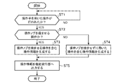
- FIG. 4 is a flowchart showing the operation input method according to Embodiment 1, showing the operation of the operation input device 2.
- the operation information generator 22 determines whether or not an operation using the operator 21 has been performed (step ST1). For example, the operation information generation unit 22 acquires detection information of an operation using the operation element 21 from at least one of the touch panel 3 and the detection unit 212, and when the acquired detection information is valid, the operation information generation unit 22 uses the operation element 21. It is determined that an operation has been performed.
- the operation information generation unit 22 determines that the detection information of the rotation of the operation knob 211 is valid, and determines that the rotation amount is less than the threshold, it is determined that the detected information is invalid. Further, the operation information generation unit 22 determines that the detection information of the operation of bending the operation knob 211 is effective when the ON time during which any one of the push button switches 212a, 212b, and 212c is in the ON state is equal to or greater than the threshold. , and if the ON time is less than the threshold, it is determined that the detection information is invalid.
- step ST1 When determining that an operation using the manipulator 21 has not been performed (step ST1; NO), the operation information generation unit 22 repeats the determination of step ST1 until an operation using the manipulator 21 is performed. When it is determined that an operation using the manipulator 21 has been performed (step ST1; YES), the operation information generation unit 22 determines whether or not the manipulation using the manipulator 21 is an operation to bend the manipulation knob 211. (step ST2).
- the operation information generation unit 22 determines that the operation using the operation element 21 is an operation to bend the operation knob 211. Further, when the valid detection information is acquired from the touch panel 3, the operation information generation unit 22 determines that the operation using the operation knob 21 is not the operation to bend the operation knob 211, and the operation using the operation element 21 It is determined that it is a rotation operation of
- the operation information generator 22 determines that the operation using the operator 21 is an operation to bend the operation knob 211 (step ST2; YES), it generates operation information including an operation to bend the operation knob 211. (Step ST3). Further, when it is determined that the operation using the manipulator 21 is not the operation to bend the manipulation knob 211 (step ST2; NO), the manipulation information generation unit 22 determines that the manipulation performed without bending the manipulation knob 211 is is generated (step ST4).
- the operation information includes, for example, the XY coordinates of the operation knob 211 calculated based on the position coordinates of the contact portions 213a to 213c of the operation knob 211 on the touch surface, the rotation direction and amount of rotation of the operation knob 211, and the push button switch. Information indicating the on or off state of 212a-212c is included.
- the operation information generation unit 22 generates operation information using valid detection information acquired from the time when valid detection information is first acquired until the reference time for determining one operation has passed. For example, if the detection information acquired within the reference time is the detection information of an operation of bending the operation knob 211, the operation information generation unit 22 moves the operation knob 211 once, similar to a mouse click operation. Operation information indicating an operation of selecting target information by bending is generated.
- the operation information generation unit 22 performs By bending the operation knob 211 twice at short intervals, operation information indicating an operation of selecting target information is generated. If the detection information acquired within the reference time is the detection information of an operation of bending the operation knob 211 three times at short intervals, the operation information generation unit 22 generates the operation knob in the same manner as the triple-click operation of the mouse. By bending 211 three times at short intervals, operation information indicating an operation for selecting target information is generated.
- the operation information generation unit 22 If the detection information acquired within the reference time is the detection information of an operation of bending the operation knob 211 four times or more at short intervals, the operation information generation unit 22 generates an operation similar to a long-click operation of the mouse. By flexing the knob 211 four times or more at short intervals, operation information indicating an operation for selecting target information is generated. Further, when the detection information acquired within the reference time is a rotation operation of the operation knob 211 in a flexed state, the operation information generation unit 22 generates an operation similar to a drag-and-drop operation using a mouse, for example. , generates operation information indicating an operation to move the target information on the display screen.
- the operation information generation unit 22 outputs the generated operation information to the function execution unit 5 (step ST5).
- the function execution unit 5 acquires operation information from the operation information generation unit 22 and executes a function corresponding to the operation indicated by the acquired operation information.
- the function execution unit 5 then outputs display information corresponding to the function being executed to the display processing unit 23 .
- the display processing unit 23 displays display information on the LCD 4 .
- the LCD 4 displays a map screen, a camera screen, a menu screen, or an audio playback screen.
- Function execution unit 5 outputs display information indicating operation details such as the XY coordinates of operation knob 211 , the rotation direction and amount of rotation of operation knob 211 included in the operation information to display processing unit 23 .
- the display processing unit 23 reflects the content of the operation based on the display information in the screen display of the function corresponding to the operation indicated by the operation information.
- the operation input device 2 includes a processing circuit for executing the processing from step ST1 to step ST5 shown in FIG.
- the processing circuit may be dedicated hardware, or may be a CPU that executes a program stored in memory.
- FIG. 5A is a block diagram showing the hardware configuration that implements the functions of the operation input device 2.
- FIG. 5B is a block diagram showing a hardware configuration for executing software realizing the functions of the operation input device 2.
- the input interface 100 includes detection information output from the detection unit 212 included in the touch panel 3 or the operator 21 to the operation information generation unit 22, or output from the function execution unit 5 to the display processing unit 23. It is an interface that relays display information.
- the output interface 101 is an interface that relays operation information output from the operation information generation unit 22 to the function execution unit 5 .
- the processing circuit 102 may be, for example, a single circuit, multiple circuits, a programmed processor, a parallel programmed processor, an ASIC, an FPGA, or any of these. A combination of is applicable.
- the functions of the operation information generation unit 22 and the display processing unit 23 in the operation input device 2 may be realized by separate processing circuits, or these functions may be collectively realized by one processing circuit.
- the processing circuit is the processor 103 shown in FIG. 5B
- the functions of the operation information generation unit 22 and the display processing unit 23 in the operation input device 2 are realized by software, firmware, or a combination of software and firmware. Note that software or firmware is written as a program and stored in the memory 104 .
- the processor 103 implements the functions of the operation information generation unit 22 and the display processing unit 23 in the operation input device 2 by reading and executing the programs stored in the memory 104 .
- the operation input device 2 includes a memory 104 for storing a program that, when executed by the processor 103, results in the processing of steps ST1 to ST5 shown in FIG. These programs cause the computer to execute the procedures or methods of the processing performed by the operation information generating section 22 and the display processing section 23 .
- the memory 104 may be a computer-readable storage medium storing a program for causing a computer to function as the operation information generating section 22 and the display processing section 23.
- the memory 104 corresponds to, for example, nonvolatile or volatile semiconductor memory such as RAM, ROM, flash memory, EPROM, EEPROM, magnetic disk, flexible disk, optical disk, compact disk, mini disk, DVD, and the like.
- a part of the functions of the operation information generation unit 22 and the display processing unit 23 in the operation input device 2 may be realized by dedicated hardware, and a part may be realized by software or firmware.
- the operation information generation unit 22 realizes its functions by the processing circuit 102, which is dedicated hardware
- the display processing unit 23 implements its functions by the processor 103 reading and executing a program stored in the memory 104.
- the processing circuitry may implement the above functions in hardware, software, firmware, or a combination thereof.
- the operation input device 2 generates the operator 21 having the operation knob 211 and the detection unit 212, the operation information indicating the operation using the operator 21, and the function execution unit 5 is provided with an operation information generation unit 22 that outputs operation information, and the operation information generation unit 22 generates operation information indicating an operation of bending the operation knob 211 detected by the detection unit 212 . Since the function to be executed can be designated by a natural operation of bending the operation knob 211 by changing the gripping force, the operation input device 2 can handle the desired function regardless of the number of fingers gripping the manipulator 21. You can perform operations to Furthermore, since a function to be executed is designated by a natural operation, the information processing apparatus 1 including the operation input device 2 reduces the possibility of erroneously executing a function different from the intended function.
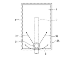
- FIG. 6 is a front view showing a configuration example of the operation input device 2A according to the second embodiment.
- the operation knob 211 included in the operation input device 2A is provided so as to be slidable in a pendulum shape on the touch surface of the touch panel 3 .
- the LCD 4 is provided with an arm 7 .
- One end of the arm 7 is rotatably supported on the back side of the LCD 4 , and the other end is bent toward the front side of the LCD 4 .
- An operation knob 211 is connected to the end portion of the arm 7 bent toward the front side of the LCD 4 .
- the operation knob 211 is slidable in the direction of arrow B on the touch surface of the touch panel 3 with one end of the arm 7 as the center of rotation. Further, the user can rotate the operating knob 211 while sliding the gripped operating knob 211 in the arrow B direction. A slide operation of the operation knob 211 is detected by the touch panel 3 . As shown in FIG. 6, a spring 7A and a spring 7B are attached to the arm 7 on the rear side of the LCD 4. As shown in FIG. When the user releases the operation knob 211, the arm 7 returns to a position where the load of the spring 7A and the load of the spring 7B are balanced, and the operation knob 211 returns to the central position of the slide movement locus.
- the mechanism for returning the operation knob 211 to the central position is not limited to the springs 7A and 7B, and magnets, dampers, or the like may be used.
- the operation knob 211 may return to the central position by the weight of the arm 7 and the operation knob 211 .
- FIG. 7 is a flow chart showing the operation input method according to Embodiment 2, and shows the operation of the operation input device 2A.
- the operation information generator 22 included in the operation input device 2A determines whether the operation knob 211 is being slid (step ST1a). For example, the operation information generator 22 acquires detection information about the amount of slide movement of the operation knob 211 from the touch panel 3, and determines that the operation knob 211 has been slid when the detection information is valid. For the determination of whether the detection information is valid or invalid, for example, when the amount of slide movement of the contact portion of the operation knob 211 on the touch surface of the touch panel 3 is equal to or greater than a threshold value, it is determined that the detection information is valid, and the amount of slide movement is determined. is less than the threshold, it is determined that the detection information is invalid.
- step ST1a When it is determined that the operation knob 211 is not being slid (step ST1a; NO), the operation input device 2A terminates the series of processes in FIG. The operation input device 2A repeatedly executes the processing of FIG. 7 until the operation knob 211 is slid.
- the operation information generation unit 22 determines whether or not an operation to bend the operation knob 211 has been performed (step ST2a). For example, the operation information generation unit 22 acquires detection information of an operation to bend the operation knob 211 from the detection unit 212, and determines that an operation to bend the operation knob 211 has been performed when the detection information is valid. Determination as to whether the switch is valid or invalid is performed, for example, by bending the operation knob 211 when the ON time during which any one of the push button switches 212a, 212b, and 212c is in the ON state is equal to or greater than a threshold. is valid, and if the ON time is less than the threshold, it is determined that the detection information is invalid.
- step ST2a NO
- the operation input device 2A terminates the series of processes in FIG. After that, the operation input device 2A outputs the operation information indicating the slide operation of the operation knob 211 to the function executing section 5.
- FIG. The function execution unit 5 acquires operation information from the operation information generation unit 22 and executes a function corresponding to the slide operation indicated by the operation information.
- the function execution unit 5 outputs display information corresponding to the function being executed to the display processing unit 23 .
- the display processing unit 23 displays display information on the LCD 4 .
- the screen display of the LCD 4 changes according to the slide operation of the operation knob 211 when the operation to bend the operation knob 211 is not performed.
- the operation information generation unit 22 determines that the operation to bend the operation knob 211 has been performed (step ST2a; YES)
- the operation information generation unit 22 generates an operation indicating a combination of the operation of sliding the operation knob 211 and the operation of bending the operation knob 211 .
- Information is generated, and the generated operation information is output to the function execution unit 5 .
- the operation information includes, for example, the slide movement amount of the operation knob 211 calculated based on the position coordinates of the contact portions 213a to 213c of the operation knob 211 on the touch surface, the XY coordinates of the operation knob 211, and the push button switches 212a to 213c. 212c is included.
- the function execution unit 5 acquires operation information from the operation information generation unit 22 and executes a function corresponding to the operation indicated by the acquired operation information.
- the function execution unit 5 then outputs display information corresponding to the function being executed to the display processing unit 23 .
- the display processing unit 23 displays display information on the LCD 4 .
- the display processing unit 23 causes the operation to bend the operation knob 211 .
- the screen display on the LCD 4 at the time of execution is maintained (step ST3a). The user can perform the slide operation of the operation knob 211 with respect to the screen display at the time when the operation of bending the operation knob 211 is performed.
- the operation information generator 22 determines whether or not the operation knob 211 has returned to the central position of the slide movement locus (step ST4a). For example, when the XY position of the operation knob 211 detected by the touch panel 3 is the center position of the slide movement trajectory, the operation information generator 22 determines that the operation knob 211 has returned to the center position of the slide movement trajectory. Further, when the XY position of the operation knob 211 is not the center position of the slide movement trajectory, the operation information generation unit 22 determines that the operation knob 211 has not returned to the center position of the slide movement trajectory.
- the operation information generation unit 22 outputs to the display processing unit 23 the determination result as to whether or not the operation knob 211 has returned to the center position of the slide movement locus.
- the display processing unit 23 cancels the maintenance of the screen display at the time when the operation to bend the operation knob 211 is performed (step ST5a).
- step ST4a determines whether or not an operation to bend the operation knob 211 has been performed.
- step ST6a determines whether or not an operation to bend the operation knob 211 has been performed.
- step ST6a If the operation knob 211 has not been returned to the central position of the slide movement locus and is not bent (step ST6a; NO), the display processing unit 23 proceeds to the process of step ST3a. Returning, the screen display of the function corresponding to the slide operation of the operation knob 211 is maintained.
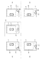
- FIG. 8 is a screen diagram showing a display example when performing processing for selecting target item information from a plurality of items of item information by an operation combining the operation of sliding the operation knob 211 and the operation of bending the operation knob 211 .
- Item information is, for example, menu information.
- the menu selection screen shown in FIG. 8 is a selection screen for selecting target item information from a plurality of item information (menu information), and is displayed on the LCD 4 provided with the touch panel 3 .
- a first list 8A and a second list 8B are displayed on the menu selection screen.
- the first list 8A is a list in which a plurality of pieces of menu information of selection candidates are displayed side by side.
- the second list 8B is a list in which a plurality of items of menu information in the first list 8A are displayed vertically.
- the menu selection screen surrounded by the dashed line with symbol C is the menu selection screen when the operation knob 211 is at the center position of the slide movement locus.
- the menu selection screen shown on the (A) side of FIG. 8 with the dashed line as the boundary shows the menu selection screen when the operation knob 211 that is not bent is slid.
- the menu selection screen shown on the (B) side of the dashed line is obtained by bending the operation knob 211 once while the menu selection screen shown on the (A) side is displayed on the LCD 4. It shows the menu selection screen when the operation knob 211 is released later and the operation knob 211 returns to the center position of the slide movement locus.
- the display processing unit 23 enlarges or reduces the display of the menu information in the second list 8B according to the slide operation of the operation knob 211. For example, in the second list 8B in the menu selection screen enclosed by the dashed line to which the symbol C is attached, the menu information is displayed with the initial value of the display magnification. When the operation knob 211 is bent while the menu information is being displayed on the LCD 4 at the initial value of the display magnification, the display processing unit 23 bends the operation knob 211 as shown in (B). Maintains the menu selection screen at the time when the operation to change is performed.
- the display processing unit 23 reduces the display of the menu information of the second list 8B.
- the display processing unit 23 maintains the menu selection screen including the second list 8B in which the display of the menu information is reduced. Thereafter, even if the user releases the operation knob 211 and slides the operation knob 211 in the direction of the arrow B3 to return to the central position, the operation to bend the operation knob 211 is not performed as shown in (B).
- the menu selection screen at the point in time is maintained. Since the screen display changed by the sliding operation of the operation knob 211 is maintained by the natural operation of bending the operation knob 211, the user can perform the next operation on the changed screen display without performing the slide operation again. It is possible.
- the display processing unit 23 enlarges the display of the menu information in the second list 8B.
- the display processing unit 23 maintains the menu selection screen including the second list 8B in which the display of the menu information is enlarged. Thereafter, even if the user releases the operation knob 211 and slides the operation knob 211 in the direction of the arrow B4 to return to the central position, the operation to bend the operation knob 211 is not performed as shown in (B).
- the menu selection screen at the point in time is maintained. Since the screen display changed by the sliding operation of the operation knob 211 is maintained by the natural operation of bending the operation knob 211, the user can perform the next operation on the changed screen display without performing the slide operation again. It is possible.
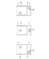
- FIG. 9 is a screen diagram showing a display example when performing a process of enlarging or reducing the bird's-eye view image of the vehicle by an operation combining the operation of sliding the operation knob 211 and the operation of bending the operation knob 211 .
- the bird's-eye view image of the vehicle is, for example, an image captured by the imaging unit 6 and displayed on the LCD 4 .
- a bird's-eye view image of the vehicle is displayed at the initial value of the display magnification on the screen 9 enclosed by the dashed line to which the symbol D is attached.
- the display processing unit 23 enlarges or reduces the bird's-eye view image of the vehicle displayed on the LCD 4 according to the slide operation of the operation knob 211 .
- the screen shown on the (A) side of the dashed line in FIG. 9 shows the screen when the operation knob 211 that is not bent is slid. Further, the screen shown on the (B) side of the dashed line is displayed on the LCD 4 when the screen shown on the (A) side is displayed on the LCD 4, and the operation knob 211 is opened after the operation of bending the operation knob 211 once. , and the operation knob 211 returns to the central position of the slide movement locus.
- the display processing unit 23 displays a bird's-eye view image of the vehicle as shown on the left side of the screen 9 surrounded by the dashed line with the symbol D. to shrink.
- the display processing unit 23 maintains the screen 9A in which the bird's-eye view image of the vehicle is reduced. Thereafter, even if the user releases the operation knob 211 and slides the operation knob 211 in the direction of the arrow B3 to return to the central position, the operation to bend the operation knob 211 is not performed as shown in (B).
- the screen 9A at the time when it was performed is maintained. Since the screen display changed by the sliding operation of the operation knob 211 is maintained by the natural operation of bending the operation knob 211, the user can perform the next operation on the changed screen display without performing the slide operation again. It is possible.
- the display processing unit 23 enlarges the bird's-eye view image of the vehicle.
- the display processing unit 23 maintains the screen 9B in which the bird's-eye view image of the vehicle is enlarged. Thereafter, even if the user releases the operation knob 211 and slides the operation knob 211 in the direction of the arrow B4 to return to the central position, the operation to bend the operation knob 211 is not performed as shown in (B).
- the screen 9B at the time when it was performed is maintained. Since the screen display changed by the sliding operation of the operation knob 211 is maintained by the natural operation of bending the operation knob 211, the user can perform the next operation on the changed screen display without performing the slide operation again. It is possible.
- FIG. 10 is a screen diagram showing a display example when the bird's-eye view image of the vehicle is slid left and right by an operation combining the operation of sliding the operation knob 211 and the operation of bending the operation knob 211 .
- the bird's-eye view image of the vehicle is, for example, an image captured by the imaging unit 6 and displayed on the LCD 4 .
- a bird's-eye view image of the vehicle at the initial position is displayed on the screen 9 surrounded by a dashed line denoted by D.
- the display processing unit 23 slides the bird's-eye view image of the vehicle displayed on the LCD 4 left and right in accordance with the slide operation of the operation knob 211 .
- the screen shown on the (A) side of FIG. 10 with the dashed line as the boundary shows the screen when the operation knob 211 that is not bent is slid. Further, the screen shown on the (B) side of the dashed line is displayed on the LCD 4 when the screen shown on the (A) side is displayed on the LCD 4, and the operation knob 211 is opened after the operation of bending the operation knob 211 once. The screen is shown when the operation knob 211 returns to the center position of the slide movement locus by releasing the hand from the .
- the display processing unit 23 displays a bird's-eye view image of the vehicle as shown on the left side of the screen 9 surrounded by the dashed line with the symbol D. slide to the right.
- the display processing unit 23 maintains the screen 9C in which the bird's-eye view image of the vehicle is slid to the right. Thereafter, even if the user releases the operation knob 211 and slides the operation knob 211 in the direction of the arrow B3 to return to the central position, the operation to bend the operation knob 211 is performed as shown in (B).
- the screen 9C at the time when it was broken is maintained. Since the screen display changed by the slide operation of the operation knob 211 is maintained by the natural operation of bending the operation knob 211, the user can perform the next operation on the changed screen display without performing the slide operation again. It is possible.
- the display processing unit 23 When the operation knob 211 is slid in the direction of arrow B2 from the center position of the slide movement locus, the display processing unit 23 enlarges the bird's-eye view image of the vehicle. At this time, when an operation to bend the operation knob 211 is performed, the display processing unit 23 maintains the screen 9D in which the bird's-eye view image of the vehicle is slid to the left. Thereafter, even if the user releases the operation knob 211 and slides the operation knob 211 in the direction of the arrow B4 to return to the central position, the operation to bend the operation knob 211 is not performed as shown in (B). The screen 9D at the time it was performed is maintained. Since the screen display changed by the sliding operation of the operation knob 211 is maintained by the natural operation of bending the operation knob 211, the user can perform the next operation on the changed screen display without performing the slide operation again. It is possible.
- FIG. 11 is a screen diagram showing a display example when CD playback processing is performed by an operation combining the operation of sliding the operation knob 211 and the operation of bending the operation knob 211 .
- the CD playback screen is a screen for selecting a track (T), volume adjustment (V) and playback speed adjustment (S), and is displayed on the LCD 4.
- T track
- V volume adjustment
- S playback speed adjustment
- FIG. 11 the volume control (V) is selected on the screen 10 surrounded by the dashed line with the symbol E.
- Function execution unit 5 selects an adjustment item on the CD playback screen according to the slide operation of operation knob 211 , and display processing unit 23 displays the selection of the adjustment item on the CD playback screen on LCD 4 .
- the screen shown on the (A) side of FIG. 11 with the dashed line as the boundary shows the screen when the operation knob 211 that is not bent is slid. Further, the screen shown on the (B) side of the dashed line is displayed on the LCD 4 when the screen shown on the (A) side is displayed on the LCD 4, and the operation knob 211 is opened after the operation of bending the operation knob 211 once. The screen is shown when the operation knob 211 returns to the center position of the slide movement locus by releasing the hand from the .
- the display processing unit 23 displays the track (T) as shown on the left side of the screen 10 surrounded by the dashed line with the symbol E.
- the selected CD playback screen 10A is displayed on the LCD 4. - ⁇ At this time, when an operation to bend the operation knob 211 is performed, the display processing unit 23 maintains the CD playback screen 10A. Thereafter, even if the user releases the operation knob 211 and the operation knob 211 slides in the direction of the arrow B3 to return to the central position, the operation to bend the operation knob 211 is performed as shown in (B).
- the CD playback screen 10A at the time of opening is maintained. Since the screen display changed by the sliding operation of the operation knob 211 is maintained by the natural operation of bending the operation knob 211, the user can perform the next operation on the changed screen display without performing the slide operation again. It is possible.
- the display processing unit 23 causes the LCD 4 to display the CD playback screen 10B with playback speed adjustment (S) selected.
- S playback speed adjustment
- the display processing section 23 maintains the CD playback screen 10B.
- the operation to bend the operation knob 211 is performed as shown in (B).
- the CD playback screen 10B at the time of opening is maintained. Since the screen display changed by the sliding operation of the operation knob 211 is maintained by the natural operation of bending the operation knob 211, the user can perform the next operation on the changed screen display without performing the slide operation again. It is possible.
- FIG. 12 is a screen diagram showing a display example when the processing of sliding the center coordinates 14 of the map around the vehicle is performed by an operation combining the operation of sliding the operation knob 211 and the operation of bending the operation knob 211 . .
- the map screen 11 is displayed on the LCD 4 by the display processing section 23 .
- An image 12 showing the current position of the vehicle and a route 13 are displayed on the map screen 11 .
- the function executing section 5 executes a navigation function of guiding the vehicle along the route 13 . Further, the function execution unit 5 changes the center coordinates 14 of the map screen in accordance with the sliding operation of the operation knob 211 that is being bent.
- the display processing unit 23 displays the change of the central coordinates 14 of the map screen on the LCD 4 .
- the display processing unit 23 moves the image 12 in the direction of the arrow F1 on the route 13,
- the LCD 4 displays a map screen 11A in which the position behind the vehicle on the route 13 is changed to the center coordinates 14.
- the display processing unit 23 moves the image 12 in the direction of arrow F2 on the route 13.
- the LCD 4 displays a map screen 11B in which the position in front of the vehicle on the route 13 is changed to the center coordinates 14.
- the image 12 indicating the current position of the vehicle may be continuously moved forward or backward on the route 13 .
- the display processing unit 23 may determine the moving distance or moving speed for moving the image 12 forward or backward on the route 13 according to the amount of slide movement of the operation knob 211 that is being bent.
- the center coordinates 14 of the map screen are changed according to the sliding operation of the operation knob 211 that is being operated to bend, when the operation knob 211 returns to the center position, the center coordinates 14 of the map screen change to the current vehicle position ( It may be displayed so as to return to the position of the image 12).
- the display processing unit 23 may enlarge or reduce the display of the map screen according to the slide operation of the operation knob 211 that has been restored from the bending. For example, the display processing unit 23 displays the map screen on the LCD 4 at a display magnification corresponding to the slide operation amount of the operation knob 211 . Further, the display processing unit 23 may change the orientation of the image displayed on the LCD 4 in accordance with the slide operation of the operation knob 211 restored from the bending. For example, the function execution unit 5 changes the direction of the imaging unit 6 (the camera swings) in accordance with the slide operation of the operation knob 211 restored from the flexure.
- the function execution unit 5 may switch the function to be executed according to the slide operation of the operation knob 211 that has been restored from the flexure.
- the display processing unit 23 switches to a screen corresponding to the function executed by the function execution unit 5 in accordance with the slide operation of the operation knob 211 restored from the bending.
- the display screen of the LCD 4 switches from a camera image display screen to a menu selection screen or switches to a map display screen in accordance with a slide operation of the operation knob 211 restored from bending.
- the function execution unit 5 may switch the function to be executed according to the slide position of the operation knob 211 restored from the flexure. For example, when the operation knob 211 moves to the first position of the slide movement trajectory, the function execution unit 5 executes the CD playback function and adjusts the volume (V) according to the rotation operation of the operation knob 211 . Furthermore, when the operation knob 211 moves to the second position (a position different from the first position) on the slide movement locus, the function execution unit 5 executes the control function of the air conditioner, and the rotation operation of the operation knob 211 Adjust temperature accordingly.
- the display processing unit 23 may change the transparency of the image displayed on the LCD 4 according to the slide position of the operation knob 211 restored from the flexure. For example, the display processing unit 23 increases the transparency of the image displayed on the LCD 4 when the operation knob 211 is slid to the left from the center position, and increases the transparency of the image displayed on the LCD 4 when the operation knob 211 is slid to the right from the center position. Reduce the transparency of the displayed image.
- the display processing unit 23 may change the amount of information to be displayed on the LCD 4 according to the slide operation of the operation knob 211 restored from the bending.
- the amount of information to be displayed on the LCD 4 includes the number of pieces of display information or the degree of detail of the content. For example, on a setting screen displaying a plurality of pieces of image information, it is conceivable to reduce the number of pieces of image information or simplify the image in accordance with the slide operation of the operation knob 211 that has been restored from bending. Although the slide operation of the operation knob 211 restored from bending has been described so far, the above process may be executed in accordance with the slide operation of the operation knob 211 that is being bent.
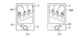
- FIG. 13A is a screen diagram showing a display example when the process of displaying the scenery after the vehicle has passed the route 13 is performed by an operation combining the operation of sliding the operation knob 211 and the operation of bending the operation knob 211.
- FIG. 13B is a screen diagram showing a display example when the process of displaying the scenery before the vehicle passes through the route 13 is performed by an operation combining the operation of sliding the operation knob 211 and the operation of bending the operation knob 211 . is.
- the image 15A or 15B of the scene outside the vehicle is displayed on the LCD 4 by the display processing unit 23.
- the image 15A or 15B of the scenery outside the vehicle may be, for example, an image captured by the imaging unit 6, or may be an existing image such as a street view.
- the function execution unit 5 changes the center coordinates 14 of the map screen according to the slide operation of the operation knob 211 that is being bent.
- the display processing unit 23 displays the image 15A or 15B of the scenery outside the vehicle at the center coordinates 14 of the map screen on the LCD 4 .
- the display processing unit 23 moves the image 12 ahead of the route 13 as shown in FIG. 13A. to change the position behind the vehicle on route 13 to center coordinates 14 . Then, the display processing unit 23 displays the image 15A of the scenery outside the vehicle at the changed center coordinates 14 on the LCD 4 . Further, an arrow F3 indicating the direction in which the vehicle exists at the center coordinates 14 may be displayed in the image 15A of the scenery outside the vehicle.
- the display processing unit 23 changes the image 12 to the route 13 as shown in FIG. 13B. By moving forward, the position ahead of the vehicle on the route 13 is changed to center coordinates 14 . Then, the display processing unit 23 displays the image 15B of the scenery outside the vehicle at the changed center coordinates 14 on the LCD 4 . Also, an arrow F4 indicating the direction in which the vehicle exists at the center coordinates 14 may be displayed in the image 15B of the scenery outside the vehicle.
- the display processing unit 23 may enlarge or reduce the display of the image 15A or 15B of the scenery outside the vehicle according to the slide operation of the operation knob 211 restored from the bending.
- FIG. 14 shows a display example when processing is performed to display the guide line 17 for reversing on the image 16 behind the vehicle by an operation combining the operation of sliding the operation knob 211 and the operation of bending the operation knob 211 . It is a screen figure.
- the display processing unit 23 displays on the LCD 4 an image 16 of the rear of the vehicle including the guide line 17 for reversing the vehicle.
- the transmittance of the guide wire 17 has an intermediate value at the center position of the slide movement locus of the operation knob 211 .
- the display processing unit 23 displays an image 16A in which the transparency of the guide line 17 is increased on the LCD 4 when the operation knob 211, which is being operated to be bent, is slid in the direction of the arrow B1 from the center position of the slide movement locus. indicate.
- the guide line 17 in the image 16A is transparent because the transparency is set to the maximum value.
- the display processing unit 23 displays the image 16B in which the transparency of the guide line 17 is lowered. Display on LCD4. The guide line 17 in the image 16B is clearly displayed because the transparency is set to the minimum value.
- FIG. 15 shows a display example when processing for displaying an obstacle warning image 19 on a vehicle bird's-eye view image 18 is performed by an operation combining a sliding operation of the operation knob 211 and an operation of bending the operation knob 211 . It is a screen figure.
- the display processing unit 23 displays on the LCD 4 a bird's-eye view image 18 of the vehicle including an obstacle warning image 19 .
- the transparency of the warning image 19 has an intermediate value at the center position of the slide movement locus of the operation knob 211 .
- the display processing unit 23 displays an image 18A obtained by increasing the transparency of the warning image 19 on the LCD 4 when the operation knob 211, which is being operated to be bent, is slid in the direction of the arrow B1 from the center position of the slide movement locus. indicate.
- the warning image 19 in the image 18A is transparent because the transparency is set to the maximum value.
- the display processing unit 23 displays the image 18B in which the transparency of the warning image 19 is lowered on the LCD 4. to display.
- the warning image 19 in the image 18B is clearly displayed because the transparency is set to the minimum value.
- FIG. 16 is a screen diagram showing a display example when processing for controlling the image pickup direction of the image pickup unit 6 that picks up an image of a person is performed by an operation combining the operation of sliding the operation knob 211 and the operation of bending the operation knob 211 . is.
- the display processing unit 23 displays an image 31 of a person captured by the imaging unit 6 on the LCD 4 .
- An image 31 of a person captured from the front is displayed on the LCD 4 at the center position of the slide movement locus of the operation knob 211 .
- the function executing unit 5 controls the imaging direction of the imaging unit 6 when the operation knob 211, which is being operated to be bent, is slid in the direction of the arrow B1 from the center position of the slide movement trajectory. 6 is changed so that the right side of the person is imaged.
- the display processing unit 23 displays on the LCD 4 an image 31A in which the right side of the person is mainly captured.
- the function execution unit 5 controls the image pickup direction of the image pickup unit 6 to perform the image pickup operation.
- the direction of the part 6 is changed so as to image the left side of the person.
- the display processing unit 23 displays on the LCD 4 an image 31B in which the left side of the person is mainly captured.
- FIG. 17 shows an example of a display when the processing for controlling the imaging direction of the imaging unit 6 that captures the bird's-eye view image 32 of the vehicle is performed by an operation combining the operation of sliding the operation knob 211 and the operation of bending the operation knob 211 . It is a screen diagram showing .
- the display processing unit 23 displays a bird's-eye view image 32 of the vehicle captured by the imaging unit 6 on the LCD 4 .
- a bird's-eye view image 32 obtained by imaging the vehicle from directly above is displayed on the LCD 4 .
- the function executing unit 5 controls the imaging direction of the imaging unit 6 when the operation knob 211, which is being operated to be bent, is slid in the direction of the arrow B1 from the center position of the slide movement trajectory. 6 is changed so as to image the left side of the vehicle.
- the display processing unit 23 displays on the LCD 4 an image 32A in which the left side of the vehicle is mainly captured.
- the function execution unit 5 controls the image pickup direction of the image pickup unit 6 to perform the image pickup operation.
- the direction of the part 6 is changed to image the right side of the vehicle.
- the display processing unit 23 displays on the LCD 4 an image 32B in which the right side of the vehicle is mainly captured.
- FIG. 18 is a screen diagram showing a display example when a process of transitioning a plurality of types of processing screens is performed by an operation combining the operation of sliding the operation knob 211 and the operation of bending the operation knob 211 .
- the display processing unit 23 displays on the LCD 4 a bird's-eye view image 32 of the vehicle taken from directly above at the center position of the slide movement locus of the operation knob 211 .
- the function execution unit 5 switches the function to be executed to the control function of the air conditioner when the operation knob 211 that is being bent is slid in the direction of the arrow G1 from the center position of the slide movement locus.
- the display processing unit 23 displays the control screen 33 of the air conditioner on the LCD 4 .
- the function execution unit 5 switches the function to be executed to the vehicle navigation function.
- the display processing unit 23 displays on the LCD 4 the map screen 11 including the route that the vehicle travels.
- the display processing unit 23 displays the image of the vehicle imaged by the imaging unit 6 attached to the vehicle.
- a front image 34 is displayed on the LCD 4.
- the display processing unit 23 displays the image of the rear of the vehicle captured by the image capturing unit 6 attached to the vehicle. is displayed on the LCD 4.
- Images corresponding to various functions executed by the function execution unit 5 can be switched in stages and displayed on the LCD 4 by a natural operation of sliding the operation knob 211 that is being bent. This allows the user to operate various functions.
- the sliding operation of the operation knob 211 that is being bent has been described so far, the above processing may be executed in response to the sliding operation of the operation knob 211 that is restored from the bending.
- FIG. 19 is a screen diagram showing a display example (1) when a process of selecting item information from a menu list is performed by an operation combining the operation of sliding the operation knob 211 and the operation of bending the operation knob 211.
- FIG. . The menu selection screen shown in FIG. 19 is a selection screen for selecting target menu information from a plurality of menu information, and is displayed on LCD 4 provided with touch panel 3 .
- a first list 8A and a second list 8B are displayed on the menu selection screen.
- the first list 8A is a list in which a plurality of pieces of menu information of selection candidates are displayed side by side.
- the second list 8B is a list in which a plurality of items of menu information in the first list 8A are displayed vertically.
- the menu selection screen surrounded by the dashed line with symbol H is the menu selection screen when the operation knob 211 is at the center position of the slide movement locus.
- the menu selection screen shown on the side (A) of FIG. 19 with the dashed line as the boundary shows the menu selection screen when the operation knob 211, which is being bent, is slid.
- the menu selection screen shown on the (B) side of the dashed line is the operation knob 211 that the user releases and returns to its flexure while the menu selection screen shown on the (A) side is displayed on the LCD 4. shows the menu selection screen when has returned to the center position of the slide movement locus.
- the function execution unit 5 selects menu information in the first list 8A and the second list 8B according to the slide operation of the operation knob 211 that is being bent. For example, in the menu selection screen enclosed by the dashed line with symbol H, the menu information 8A4 of the first list 8A is selected and the menu information 8B4 of the second list 8B is selected.
- the operation knob 211 that has been flexed returns to the center position of the slide movement trajectory.
- the display processing unit 23 maintains the menu selection screen at the time when the deflection is restored, as shown in (B) side.
- function execution unit 5 selects menu information 8A1 of first list 8A according to the slide movement amount of operation knob 211. , selects the menu information 8B1 of the second list 8B.
- the display processing unit 23 displays on the LCD 4 the first list 8A in which the menu information 8A1 is selected and the second list 8B in which the menu information 8B1 is selected.
- the operation knob 211 that has been restored to its flexure slides in the direction of the arrow B3.
- the display processing unit 23 returns to the center position of the slide movement trajectory by pressing, the display processing unit 23 maintains the menu selection screen at the time when the deflection is restored, as shown in (B) side.
- the function execution unit 5 changes the menu information 8A7 of the first list 8A according to the slide movement amount of the operation knob 211. Select to select the menu information 8B7 of the second list 8B.
- the display processing unit 23 displays on the LCD 4 the first list 8A in which the menu information 8A7 is selected and the second list 8B in which the menu information 8B7 is selected.
- the operation knob 211 that has been restored to its flexure slides in the direction of the arrow B4.
- the display processing unit 23 returns to the center position of the slide movement trajectory by pressing, the display processing unit 23 maintains the menu selection screen at the time when the deflection is restored, as shown in (B) side.
- the screen display changed by the slide operation of the operation knob 211 is maintained by the natural operation of bending the operation knob 211, so that the user can change the screen display without performing the slide operation again. It is possible to: Although the sliding operation of the operation knob 211 that is being bent has been described so far, the above processing may be executed in response to the sliding operation of the operation knob 211 that is restored from the bending.
- FIG. 20 is a screen diagram showing a display example (2) when the process of selecting item information from the menu list is performed by an operation combining the operation of sliding the operation knob 211 and the operation of bending the operation knob 211.
- the menu selection screen shown in FIG. 20 is a selection screen for selecting target menu information from a plurality of menu information, and is displayed on the LCD 4 provided with the touch panel 3 .
- a first list 8A and a second list 8B are displayed on the menu selection screen.
- the first list 8A is a list in which a plurality of pieces of menu information of selection candidates are displayed side by side.
- the second list 8B is a list in which a plurality of items of menu information in the first list 8A are displayed vertically.
- the menu selection screen enclosed by the dashed line with symbol I is the menu selection screen when the operation knob 211 is at the center position of the slide movement locus.
- the menu selection screen shown on the (A) side of the broken line in FIG. 20 shows the menu selection screen when the operation knob 211, which is being bent, is slid.
- the menu selection screen shown on the (B) side of the dashed line is the operation knob 211 that the user releases and returns to its flexure while the menu selection screen shown on the (A) side is displayed on the LCD 4. shows the menu selection screen when has returned to the center position of the slide movement locus.
- the function execution unit 5 selects menu information in the first list 8A and the second list 8B according to the slide operation of the operation knob 211 that is being bent. For example, in the menu selection screen surrounded by the dashed line with symbol I, the menu information D is selected in the first list 8A and the second list 8B. Menu information D is menu information displayed at the center position in the first list 8A and the second list 8B.
- function execution unit 5 changes first list 8A and second list 8B according to the amount of slide movement of operation knob 211.
- Select menu information A The display processing unit 23 displays on the LCD 4 the first list 8A and the second list 8B in which the menu information A is selected.
- the operation knob 211 which has been restored to its flexure, slides in the arrow B3 direction.
- the menu information A is moved to the center position in the first list 8A and the second list 8B, as shown in (B).
- the function execution unit 5 changes the first list 8A and the second list 8B according to the slide movement amount of the operation knob 211.
- Select menu information F The display processing unit 23 displays on the LCD 4 the first list 8A and the second list 8B in which the menu information F is selected.
- the display processing unit 23 displays the first list 8A and the second list 8B in which the menu information F is selected on the LCD 4, the operation knob 211, which has been restored to its flexure, slides in the arrow B4 direction. After returning to the center position of the slide movement trajectory, the menu information F is moved to the center position in the first list 8A and the second list 8B, as shown in (B).
- the menu information selected by the sliding operation of the operation knob 211 is displayed at the center position of the list by the natural operation of bending the operation knob 211, so that the user can select by sliding the operation knob 211.
- menu information can be accurately viewed.
- the sliding operation of the operation knob 211 that is being bent has been described so far, the above processing may be executed in response to the sliding operation of the operation knob 211 that is restored from the bending.
- FIG. 21 is a screen diagram showing a display example when the process of selecting item information from the menu list is performed by an operation combining the operation of rotating the operation knob 211 and the operation of bending the operation knob 211 .
- the menu selection screen shown in FIG. 21 is a selection screen for selecting target menu information from a plurality of menu information, and is displayed on the LCD 4 provided with the touch panel 3 .
- a second list 8B is displayed on the menu selection screen.
- a second list 8B is a list in which a plurality of pieces of menu information are displayed vertically.
- the function execution unit 5 selects menu information in the second list 8B according to the rotation operation of the operation knob 211 that is being bent.
- the display processing unit 23 displays on the LCD 4 the second list 8B in which the menu information B is selected according to the rotation operation of the operation knob 211 . From this state, when the operation knob 211 that is being operated to be bent is rotated in the direction of the arrow C1, the display processing unit 23 changes the display order of the menu information B in the second list 8B as shown in FIG. is replaced with the adjacent menu information C. When the operation knob 211 that is being bent is further rotated in the direction of the arrow C2, the display processing unit 23 replaces the display order of the menu information B with the adjacent menu information D in the second list 8B.
- the operation of bending the operation knob 211 and the recovery from the bending of the operation knob 211 are continuously performed like a double-click operation of a mouse.
- the display processing unit 23 can change the display order in the list between the selected menu information and the adjacent menu information. good. Even with this operation, the user can easily perform complicated processing such as changing the display order of the menu information in the list.
- FIG. 22 is a screen diagram showing a display example when a process of rotating the map around the vehicle is performed by an operation combining the operation of rotating the operation knob 211 and the operation of bending the operation knob 211 .
- the display processing unit 23 displays the map screen 11 on the LCD 4 .
- the display processing unit 23 rotates the map screen 11 according to the rotation operation of the operation knob 211 that is being bent.
- the display processing unit 23 rotates the map screen 11 in the direction of arrow D2 as shown in FIG. Further, when the operation knob 211 that is being bent is rotated in the direction of arrow C3, the display processing unit 23 rotates the map screen 11 in the direction of arrow D1.
- the direction of the map can be changed by a natural operation of bending and rotating the operation knob 211 .
- FIG. 23 is a screen diagram showing a display example when processing for changing the direction of the image around the vehicle is performed by an operation combining the operation of rotating the operation knob 211 and the operation of bending the operation knob 211 .
- the display processing unit 23 displays images 36A and 36B around the vehicle on the LCD 4 .
- the images 36A and 36B around the vehicle may be, for example, images captured by the imaging unit 6, or may be existing images such as street view.
- the display processing unit 23 changes the orientation of the image around the vehicle in accordance with the rotation operation of the operation knob 211 that is being bent. For example, when the operation knob 211 that is being operated to bend is rotated in the direction of arrow D1, an image 36A of the surroundings of the vehicle, in which the left side of the road of the vehicle is captured, is displayed on the LCD 4 as shown in FIG. . When the operation knob 211 that is being operated to bend is rotated in the direction of the arrow D2, the display processing unit 23 displays on the LCD 4 an image 36B of the surroundings of the vehicle, in which the right side of the road of the vehicle is captured. In this way, the orientation of the image around the vehicle can be changed by a natural operation of bending and rotating the operation knob 211 .
- the operation knob 211 is provided so as to be slidably operated in a pendulum shape on the touch surface of the touch panel 3 .
- the operation information generation unit 22 generates operation information indicating an operation combining a sliding operation of the operation knob 211 and an operation of bending the operation knob 211 .
- the operation input device 2A can specify a function to be executed by an operation of sliding the operation knob 211 and an operation of bending the operation knob 211 by changing the gripping force. Therefore, the operation input device 2A can perform an operation corresponding to a desired function regardless of the number of fingers holding the operator 21 .
- the information processing apparatus 1 provided with the operation input device 2A can perform a function different from the intended function. is less likely to be executed incorrectly.
- the display processing unit 23 performs the operation of bending the operation knob 211 and the recovery from the bending of the operation knob 211.
- the screen display on the LCD 4 is maintained.
- the screen display changed by the sliding operation of the operation knob 211 is maintained by the natural operation of bending the operation knob 211 . This allows the user to perform the next operation on the changed screen display without performing the slide operation again.
- the operation information generation unit 22 performs an operation in which the operation of sliding the operation knob 211, the operation of bending the operation knob 211, and the recovery from the bending of the operation knob 211 are combined. Generates the operation information shown.
- the operation input device 2 ⁇ /b>A can perform the desired operation regardless of the number of fingers gripping the manipulator 21 by natural manipulations such as the sliding manipulation of the manipulation knob 211 , the manipulation of bending the manipulation knob 211 , and the recovery from the flexing of the manipulation knob 211 . You can perform operations corresponding to the functions of
- the display processing unit 23 causes the screen display of the LCD 4 to be displayed when the operation knob 211 is restored from the bending during the sliding operation of the operation knob 211 which is being operated to be bent. maintain.
- the screen display changed by the slide operation of the operation knob 211 is maintained by the natural operation of bending the operation knob 211 and then restoring the bending. This allows the user to perform the next operation on the changed screen display without performing the slide operation again.
- the display processing unit 23 displays on the LCD 4 a selection screen for selecting menu information from a list of a plurality of item information, and the operation knob 211 being bent is operated.
- the operation knob 211 is restored from the flexure with the menu information selected from the list by the slide operation, the selected menu information is moved to the center position of the list.
- the menu information selected by the sliding operation of the operation knob 211 is displayed at the center position of the list by the natural operation of bending the operation knob 211 . Thereby, the user can accurately visually recognize the menu information selected by the slide operation of the operation knob 211 .
- the operation information generator 22 indicates an operation in which a rotation operation of the operation knob 211, an operation of bending the operation knob 211, and a recovery from the bending of the operation knob 211 are combined. Generate operational information.
- the operation input device 2A can be operated by a natural combination of rotating the operation knob 211, bending the operation knob 211, and restoring the operation knob 211 from the bending. You can perform the operation corresponding to the desired function.
- the display processing unit 23 displays on the LCD 4 a selection screen for selecting menu information from a list of a plurality of menu information, and the operation knob 211 being bent is operated.
- the display order in the list is changed between the selected menu information and the adjacent menu information. Complicated processing such as changing the display order of menu information in the list can be easily performed by a natural operation of bending the operation knob 211 .
- the display processing unit 23 displays on the LCD 4 a selection screen for selecting menu information from a list of a plurality of menu information.
- the operation knob 211 is rotated after the return from the display is performed a plurality of times in succession, the display order in the list is changed between the selected menu information and the adjacent menu information.
- a complex process of changing the display order of menu information in the list can be easily performed by a natural operation of bending the operation knob 211 and then restoring the bending.
- the operation input device can be used, for example, in a navigation device mounted on a vehicle.
- 1 Information processing device 2, 2A Operation input device, 3 Touch panel, 4 LCD, 5 Function execution unit, 6 Imaging unit, 7 Arm, 7A, 7B Spring, 8A First list, 8A1, 8B1, 8A4, 8B4, 8A7 , 8B7 Menu information, 8B Second list, 9, 9A to 9D, 10 Screen, 10A, 10B CD playback screen, 11, 11A, 11B Map screen, 12, 15A, 15B, 31, 31A, 31B, 32A, 32B Image, 13 Route, 14 Center coordinates, 16, 16A, 16B, 18A, 18B, 34, 35, 36A, 36B Video, 17 Guide line, 18, 32 Overhead video, 19 Warning image, 21 Operator, 22 Operation information generation section, 23 display processing section, 33 control screen, 100 input interface, 101 output interface, 102 processing circuit, 103 processor, 104 memory, 211 operation knob, 211A outer frame section, 211B inner frame section, 212 detection section, 212a to 212c Push button switch, 213a to 213c Contact parts.
Landscapes
- Engineering & Computer Science (AREA)
- General Engineering & Computer Science (AREA)
- Theoretical Computer Science (AREA)
- Human Computer Interaction (AREA)
- Physics & Mathematics (AREA)
- General Physics & Mathematics (AREA)
- User Interface Of Digital Computer (AREA)
Priority Applications (2)
| Application Number | Priority Date | Filing Date | Title |
|---|---|---|---|
| PCT/JP2021/015938 WO2022224328A1 (ja) | 2021-04-20 | 2021-04-20 | 操作入力装置、情報処理装置および操作入力方法 |
| JP2023515911A JPWO2022224328A1 (https=) | 2021-04-20 | 2021-04-20 |
Applications Claiming Priority (1)
| Application Number | Priority Date | Filing Date | Title |
|---|---|---|---|
| PCT/JP2021/015938 WO2022224328A1 (ja) | 2021-04-20 | 2021-04-20 | 操作入力装置、情報処理装置および操作入力方法 |
Publications (1)
| Publication Number | Publication Date |
|---|---|
| WO2022224328A1 true WO2022224328A1 (ja) | 2022-10-27 |
Family
ID=83722078
Family Applications (1)
| Application Number | Title | Priority Date | Filing Date |
|---|---|---|---|
| PCT/JP2021/015938 Ceased WO2022224328A1 (ja) | 2021-04-20 | 2021-04-20 | 操作入力装置、情報処理装置および操作入力方法 |
Country Status (2)
| Country | Link |
|---|---|
| JP (1) | JPWO2022224328A1 (https=) |
| WO (1) | WO2022224328A1 (https=) |
Citations (2)
| Publication number | Priority date | Publication date | Assignee | Title |
|---|---|---|---|---|
| US20160294387A1 (en) * | 2013-12-18 | 2016-10-06 | Diehl Ako Stiftung & Co. Kg | Operating device and appliance having the device |
| WO2019073538A1 (ja) * | 2017-10-11 | 2019-04-18 | 三菱電機株式会社 | タッチパネル式ディスプレイ装置 |
Family Cites Families (6)
| Publication number | Priority date | Publication date | Assignee | Title |
|---|---|---|---|---|
| US5489922A (en) * | 1993-12-08 | 1996-02-06 | Hewlett-Packard Company | Hand worn remote computer mouse |
| JP2011003074A (ja) * | 2009-06-19 | 2011-01-06 | Sharp Corp | 入力方法、入力装置及び電気機器 |
| DE102013008567A1 (de) * | 2013-05-17 | 2014-11-20 | Diehl Ako Stiftung & Co. Kg | Betätigungselement |
| US9766705B2 (en) * | 2015-06-15 | 2017-09-19 | Motorola Solutions, Inc. | Stationary interface control and method for using the same |
| JP2017138738A (ja) * | 2016-02-02 | 2017-08-10 | 富士通テン株式会社 | 入力装置、表示装置および入力装置の制御方法 |
| JP6667732B2 (ja) * | 2017-10-11 | 2020-03-18 | 三菱電機株式会社 | 表示制御装置、表示制御方法、表示制御プログラム、および、電子機器 |
-
2021
- 2021-04-20 WO PCT/JP2021/015938 patent/WO2022224328A1/ja not_active Ceased
- 2021-04-20 JP JP2023515911A patent/JPWO2022224328A1/ja active Pending
Patent Citations (2)
| Publication number | Priority date | Publication date | Assignee | Title |
|---|---|---|---|---|
| US20160294387A1 (en) * | 2013-12-18 | 2016-10-06 | Diehl Ako Stiftung & Co. Kg | Operating device and appliance having the device |
| WO2019073538A1 (ja) * | 2017-10-11 | 2019-04-18 | 三菱電機株式会社 | タッチパネル式ディスプレイ装置 |
Also Published As
| Publication number | Publication date |
|---|---|
| JPWO2022224328A1 (https=) | 2022-10-27 |
Similar Documents
| Publication | Publication Date | Title |
|---|---|---|
| CN105190477B (zh) | 用于在增强现实环境中的用户交互的头戴式显示装置 | |
| EP3759711B1 (en) | Methods, systems, and media for object grouping and manipulation in immersive environments | |
| US8666115B2 (en) | Computer vision gesture based control of a device | |
| CN108536273B (zh) | 基于手势的人机菜单交互方法与系统 | |
| JP6464138B2 (ja) | ジェスチャによるタッチ入力の向上 | |
| US9489040B2 (en) | Interactive input system having a 3D input space | |
| CN104793868B (zh) | 用于控制媒体应用操作的方法和装置 | |
| US9836146B2 (en) | Method of controlling virtual object or view point on two dimensional interactive display | |
| JP5201999B2 (ja) | 入力装置、及びその方法 | |
| US20100079413A1 (en) | Control device | |
| JP2010184600A (ja) | 車載用ジェスチャースイッチ装置 | |
| JP2011253468A (ja) | 表示装置、表示方法、及び表示プログラム | |
| TW201101144A (en) | A user interface | |
| US20130293460A1 (en) | Computer vision based control of an icon on a display | |
| JP2006209563A (ja) | インターフェース装置 | |
| US20140053115A1 (en) | Computer vision gesture based control of a device | |
| JP4626860B2 (ja) | 操作装置 | |
| JP6481156B2 (ja) | 入力表示装置 | |
| WO2022224328A1 (ja) | 操作入力装置、情報処理装置および操作入力方法 | |
| KR102660501B1 (ko) | 에어 제스처를 이용하여 차량 내의 표시화면을 조작하는 장치 및 방법 | |
| JP6727441B2 (ja) | 操作支援装置および操作支援方法 | |
| CN102063248A (zh) | 信息处理设备、信息处理方法和程序 | |
| CN108958588A (zh) | 界面图标操作的控制方法、系统、设备及可读存储介质 | |
| WO2017188098A1 (ja) | 車載用情報処理システム | |
| CN116271802B (zh) | 一种交互处理方法、装置及电子设备 |
Legal Events
| Date | Code | Title | Description |
|---|---|---|---|
| 121 | Ep: the epo has been informed by wipo that ep was designated in this application |
Ref document number: 21937826 Country of ref document: EP Kind code of ref document: A1 |
|
| ENP | Entry into the national phase |
Ref document number: 2023515911 Country of ref document: JP Kind code of ref document: A |
|
| NENP | Non-entry into the national phase |
Ref country code: DE |
|
| 122 | Ep: pct application non-entry in european phase |
Ref document number: 21937826 Country of ref document: EP Kind code of ref document: A1 |