WO2022220140A1 - 案内装置 - Google Patents
案内装置 Download PDFInfo
- Publication number
- WO2022220140A1 WO2022220140A1 PCT/JP2022/016223 JP2022016223W WO2022220140A1 WO 2022220140 A1 WO2022220140 A1 WO 2022220140A1 JP 2022016223 W JP2022016223 W JP 2022016223W WO 2022220140 A1 WO2022220140 A1 WO 2022220140A1
- Authority
- WO
- WIPO (PCT)
- Prior art keywords
- rolling
- curvature
- contact
- guide device
- bearing
- Prior art date
- Legal status (The legal status is an assumption and is not a legal conclusion. Google has not performed a legal analysis and makes no representation as to the accuracy of the status listed.)
- Ceased
Links
Images








Classifications
-
- B—PERFORMING OPERATIONS; TRANSPORTING
- B65—CONVEYING; PACKING; STORING; HANDLING THIN OR FILAMENTARY MATERIAL
- B65G—TRANSPORT OR STORAGE DEVICES, e.g. CONVEYORS FOR LOADING OR TIPPING, SHOP CONVEYOR SYSTEMS OR PNEUMATIC TUBE CONVEYORS
- B65G21/00—Supporting or protective framework or housings for endless load-carriers or traction elements of belt or chain conveyors
- B65G21/20—Means incorporated in, or attached to, framework or housings for guiding load-carriers, traction elements or loads supported on moving surfaces
- B65G21/22—Rails or the like engaging sliding elements or rollers attached to load-carriers or traction elements
-
- B—PERFORMING OPERATIONS; TRANSPORTING
- B65—CONVEYING; PACKING; STORING; HANDLING THIN OR FILAMENTARY MATERIAL
- B65G—TRANSPORT OR STORAGE DEVICES, e.g. CONVEYORS FOR LOADING OR TIPPING, SHOP CONVEYOR SYSTEMS OR PNEUMATIC TUBE CONVEYORS
- B65G35/00—Mechanical conveyors not otherwise provided for
-
- F—MECHANICAL ENGINEERING; LIGHTING; HEATING; WEAPONS; BLASTING
- F16—ENGINEERING ELEMENTS AND UNITS; GENERAL MEASURES FOR PRODUCING AND MAINTAINING EFFECTIVE FUNCTIONING OF MACHINES OR INSTALLATIONS; THERMAL INSULATION IN GENERAL
- F16C—SHAFTS; FLEXIBLE SHAFTS; ELEMENTS OR CRANKSHAFT MECHANISMS; ROTARY BODIES OTHER THAN GEARING ELEMENTS; BEARINGS
- F16C29/00—Bearings for parts moving only linearly
- F16C29/04—Ball or roller bearings
Definitions
- the present invention relates to a guide device.
- Japanese Unexamined Patent Application Publication No. 2002-200003 discloses a guide device as a conveying device that includes a main body that is a moving member that moves along a guide rail that is a track member.
- a pair of roller members are arranged in the main body of the conveying device disclosed in Patent Document 1 so as to sandwich both side surfaces of the guide rail, and two sets of the pair of roller members are installed on the main body.
- the present invention has been made in view of the problems that exist in the above-mentioned prior art, and it is an object of the present invention to provide a guide device that can smoothly move along track members of any shape.
- a guide device includes a track member formed to extend in a longitudinal direction including a linear portion formed in a straight line or a curved portion formed in an arc shape with a predetermined curvature radius, and a longitudinal portion of the track member.
- a pair of moving members that move relatively linearly or curvilinearly along a direction, and are arranged to sandwich the track member from both sides of the track member in a direction orthogonal to the moving direction of the moving member.
- a guide mechanism comprising a rolling element and a rolling element holding portion that rotatably holds the pair of rolling elements and is rotatably installed with respect to the moving member is provided at least with respect to the moving member.
- a guide device installed as a set, wherein a portion of the raceway member that contacts the rolling element is a rolling surface having a constant curvature, and a portion of the rolling element that contacts the rolling surface has a constant curvature. and the curvature of the rolling contact surface is different from that of the load rolling contact surface.
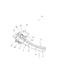
- FIG. 1 is an external perspective view of the guide device according to the present embodiment when viewed from above.
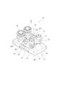
- FIG. 2 is an external perspective view of the guide device according to the present embodiment when viewed from below.
- FIG. 3 is a front view of the guide device according to this embodiment.
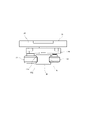
- FIG. 4 is a bottom view of the guide device according to this embodiment.
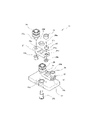
- FIG. 5 is an external perspective view of the moving member of the guide device according to the present embodiment as viewed from below. 6 is an exploded perspective view showing a disassembled state of one set of guide mechanisms among the two sets of guide mechanisms of the moving member shown in FIG. 5.
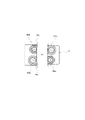
- FIG. 7A and 7B are diagrams for explaining advantageous effects of the guide device according to the present embodiment, in which part (a) shows the present embodiment and part (b) shows a comparative example. ing.
- FIG. 8 is a diagram showing a modification example in which the present invention is applied to a track rail having a shape different from that of the track rail of this embodiment.
- FIG. 9 is a schematic diagram showing one possible configuration example of the guide mechanism of the guide device according to the present invention.
- FIG. 10 is a schematic diagram showing one possible configuration example of the guide mechanism of the guide device according to the present invention.
- FIG. 11 is a schematic diagram showing still another configuration example that the guide mechanism of the guide device according to the present invention can have.
- 12A and 12B are schematic diagrams showing various contact structure examples that can be taken by the guide device of the present invention.
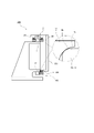
- FIG. 13 is a diagram showing a configuration example of a guide device according to another embodiment of the present invention.
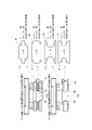
- FIG. 14 is a diagram for explaining the operating state of the guide device according to another embodiment of the present invention shown in FIG.
- FIG. 15 is a diagram showing a configuration example of a guide device according to still another embodiment of the present invention.
- FIG. 16 is a diagram for explaining the operating state of the guide device according to still another embodiment of the present invention shown in FIG.
- FIG. 1 is an external perspective view of the guide device according to this embodiment when viewed from above
- FIG. 2 is an external perspective view of the guide device according to this embodiment when viewed from below
- 3 is a front view of the guide device according to this embodiment
- FIG. 4 is a bottom view of the guide device according to this embodiment.
- FIG. 5 is an external perspective view of the moving member of the guide device according to the present embodiment when viewed from below
- FIG. FIG. 4 is an exploded perspective view showing a state in which one set of guide mechanisms is disassembled;
- the guide device 10 As shown in FIGS. 1 to 4, the guide device 10 according to the present embodiment has track rails 11 as track members of the present invention and moving bodies 21 as moving members of the present invention.
- the track rail 11 of the present embodiment is a long member that extends in the longitudinal direction. Further, the track rail 11 of the present embodiment includes a linear portion 12 formed in a straight line shape and a curved portion 13 formed in an arc shape with a predetermined radius of curvature. In the track rail 11 of the present embodiment shown in FIGS. 1 to 4, one linear portion 12 and one curved portion 13 are joined together. The obtained configuration is not limited to this configuration example.
- the track rail 11 as a track member according to the present invention may be, for example, formed by connecting only a plurality of linear portions 12 or by connecting only a plurality of curved portions 13. , a plurality of linear portions 12 and a plurality of curved portions 13 may be connected in any number and in any order.
- the track rail 11 of this embodiment is formed with a plurality of mounting holes 14 penetrating the track rail 11 in the vertical direction.
- the track rail 11 of the present embodiment can be fixed, for example, to a base surface serving as a mounting reference, with the bottom side of the track rail 11 as a reference.
- the track rail 11 of the present embodiment is formed in a projecting shape in which the left and right side surfaces of the rail protrude to the left and right.
- the projecting shapes arranged on each of the left and right side surfaces of the track rail 11 are two slopes 11a arranged on each of the upper and lower sides and inclined at an angle of 45 degrees or ⁇ 45 degrees with respect to the horizontal plane, and these two upper and lower slopes 11a. 11a and one plane 11b formed vertically between the planes 11a.
- the two upper and lower slopes 11a and one flat surface 11b forming the projecting shape exhibit the function as the rolling surface according to the present invention by receiving contact from the load rolling surface of the rolling element of the present invention, which will be described later. .
- the moving body 21 of this embodiment is a member that moves relatively linearly or curvilinearly along the longitudinal direction of the track rail 11 described above. As shown in more detail in FIGS. 5 and 6, the moving body 21 of this embodiment is composed of one moving plate 22 and two sets of guide mechanisms 23 installed on this moving plate 22. ing.
- the moving plate 22 can move the external member linearly or curvilinearly along the longitudinal direction of the track rail 11, for example, by attaching an external member to be conveyed on the upper surface side.
- the guide mechanism 23 of this embodiment includes a rolling element holding portion 24 that is rotatably installed with respect to the moving plate 22 and a state that is rotatable with respect to the rolling element holding portion 24 . It has a wheel 25 and a cam follower 26 which are a pair of rolling elements that are held by.
- the rolling element holding portion 24 has one through hole 24a at the central position, and two rolling element mounting holes 24b at positions on both sides of the through hole 24a. Then, the holder mounting shaft 24c is passed through the holder mounting hole 22a formed in the moving plate 22, and the tip of the holder mounting shaft 24c is passed through the central through hole 24a of the rolling element holder 24. By fastening and fixing the nut 24 d in this state, the rolling element holding portion 24 can be installed in a rotatable state with respect to the moving plate 22 .
- one of the two rolling element mounting holes 24b of the rolling element holding portion 24 (on the left side of the paper surface in FIG. 6) has a wheel shaft 25a of the wheel 25 passing therethrough.
- the wheel 25 can be installed in a rotatable state with respect to the rolling element holding portion 24 .
- the other (on the right side of the paper surface in FIG. 6) of the rolling element mounting hole 24b has an eccentricity when it is attached to the rolling element mounting hole 24b.
- the cam follower shaft 26a of the cam follower 26 By screwing the cam follower shaft 26a of the cam follower 26 through the eccentric through hole 27a, the shaft end of the cam follower shaft 26a is fastened and fixed by the nut 26b. , the cam follower 26 can be installed in a rotatable state with respect to the rolling element holding portion 24 .
- the position of the eccentric through-hole 27a is changed by rotating the eccentric nut 27 with respect to the rolling element mounting hole 24b. can be changed. This change in position (distance) is used when the moving body 21 is attached to the track rail 11 .
- the wheel 25 and cam follower 26 which are a pair of rolling elements that constitute the guide mechanism 23 described above, move the track rail 11 in a direction orthogonal to the moving direction of the moving body 21. They are arranged so as to sandwich the track rail 11 from both sides.
- the cam follower 26 arranged on the other side of the track rail 11 (the right side of the paper surface in FIG. 4) is configured to have a smaller diameter than the wheel 25 arranged on the side (the left side of the paper surface in FIG. 4).
- a small-diameter cam follower 26 is arranged on the inner peripheral side of the curved portion 13 formed in an arc shape with a predetermined radius of curvature on the track rail 11.
- a large-diameter wheel 25 is arranged on the outer peripheral side of the curved portion 13 .
- the wheel 25 and the cam follower 26, which are a pair of rolling elements move so that the line connecting their centers of rotation is orthogonal to the longitudinal centerline of the track rail 11. Therefore, if the wheel 25 and the cam follower 26, which are a pair of rolling elements, have the same diameter, the rolling elements arranged on the inner peripheral side of the curved portion 13 when moving on the curved portion 13 of the track rail 11 Since the distance between the rolling elements becomes small, it becomes necessary to configure the guide mechanism 23 in consideration of the distance between the rolling elements, and there is a limit to the compactness of the moving body 21 having the two sets of guide mechanisms 23 . It will happen.
- the cam followers 26, which are rolling elements arranged on the inner peripheral side of the curved portion 13 of the track rail 11, for the rolling elements of the two sets of guide mechanisms 23 have a small diameter. As a result, even if the distance between the rolling elements becomes small, the rolling elements do not come into contact with each other and interfere with each other. It is possible to realize a compact size of the moving body 21 having.
- the wheel 25 and the cam follower 26 which are a pair of rolling elements, have two upper and lower slopes forming a projecting shape on the outer peripheral side of the track rail 11. 11a, and the cam follower 26 is in line contact with one flat surface 11b forming a projecting shape on the inner peripheral side of the track rail 11. As shown in FIG.
- the guide device 10 of the present embodiment as shown in FIG.
- the portions ( The rolling contact surface, which is the upper and lower slopes 11a), is an Ra face having a constant curvature
- the load rolling contact surface which is the outer shape part of the rolling element (wheel 25) in contact with the Ra face
- the Rb surface can be configured such that the Ra surface and the Rb surface are in point contact.
- the Ra surface and the Rb surface that are in point contact can be configured to have different curvatures. For example, as shown in FIG.
- the wheel 25 and the cam follower 26, which are a pair of rolling elements arranged in the guide mechanism 23, are configured to contact the track rail 11 at two points and one line.
- FIG. 7 is a diagram for explaining advantageous effects of the guide device according to the present embodiment. shows an example.
- the track rail 11 that constitutes the guide device 10 according to the present embodiment is formed in a projecting shape in which the left and right side surfaces of the rail protrude to the left and right.
- the position (distance) of the pair of rolling elements can be changed by using the eccentric nut 27 . Changing the position (distance) between the pair of rolling elements is a mechanism that can be used when removing or attaching the moving body 21 from the track rail 11 .
- the pair of rolling elements constituting the guide mechanism of the present invention is composed of a wheel 25 and a cam follower 26, and the cam follower 26
- the wheel 25 makes point contact with the two upper and lower slopes 11a that form the protruding shape on the outer peripheral side of the track rail 11
- the cam follower 26 forms the protruding shape on the inner peripheral side of the track rail 11. It will be in line contact with one plane 11b to form. Therefore, the amount of eccentricity of the wheel 25 and the cam follower 26 when removing the moving body 21 from the track rail 11 is only the horizontal distance "e" of the slope 11a on the wheel 25 side.
- the pair of rolling elements constituting the guide mechanism of the present invention is composed of the wheel 25 and the cam follower 26 as in the present embodiment, the movement of the moving body 21 from the track rail 11 is greater than in the comparative example. Since it is possible to reduce the eccentricity of the rolling elements when removing or attaching them, it is possible to realize the guide device 10 with excellent operability.
- the track rail 11 which is the track member of the present invention, is formed in a projecting shape in which the left and right side surfaces of the rail protrude left and right, as shown in FIG.
- the guiding device of the present invention is applicable to any shape of track member.
- FIG. 8 is a diagram showing a modification example in which the present invention is applied to a track rail having a shape different from that of the track rail of the present embodiment.
- the present invention can also be applied to a track rail 81 in which the left and right side surfaces of the rail are recessed inward from the left and right sides.
- the pair of rolling elements that constitute the guide mechanism of the present invention can be composed of the large-diameter wheel 25 and the small-diameter wheel 86 .
- the large-diameter wheel 25 is in point contact with the upper and lower slopes 11a forming a concave shape on the outer peripheral side of the track rail 81 (the left side of the paper surface of FIG. 8).
- 86 is in line contact with one plane 11b forming a concave shape on the inner peripheral side of the track rail 81 (on the right side of the paper surface of FIG. 8).
- the large-diameter wheel 25 and the small-diameter wheel 86 which are a pair of rolling elements arranged in the guide mechanism 23, are arranged on the track rail 81 as in the case of the above-described embodiment.
- the moving body 21 can smoothly move along the longitudinal direction of the track rail 81 while maintaining a stable mounting state with respect to the track rail 81. It's becoming
- the rolling elements 96 arranged on the other side (inner peripheral side) of the track rail 11 in the orthogonal direction have a smaller diameter than the rolling elements 95 arranged on one side (outer peripheral side) of the track rail 11
- the configuration has been described as an example. That is, in this example, the rolling elements 96 arranged on the inner peripheral side of the track rail 11 including the arc-shaped curved portion 13 with a predetermined radius of curvature are smaller in diameter than the rolling elements 95 arranged on the outer peripheral side.
- the configuration of the guide device according to the present invention is not limited to that described above. For example, as shown in FIG.
- a pair of rolling elements 105a and 106a arranged in one set of the guide mechanisms 23a and 23b among the two sets of guide mechanisms 23a and 23b are perpendicular to the movement direction of the moving body 21.
- the rolling element 106a arranged on the other side of the track rail 11 (the right side of the paper surface of FIG. 10) has a smaller diameter than the rolling element 105a arranged on the one side of the track rail 11 (the left side of the paper surface of FIG. 10).
- the pair of rolling elements 105b and 106b arranged in the other set of guide mechanisms 23b are arranged on the other side of the track rail 11 in the direction orthogonal to the moving direction of the moving body 21 (the right side of the paper surface of FIG. 10).
- a rolling element 105b arranged on one side of the track rail 11 (the left side of the paper surface of FIG. 10) has a smaller diameter than the rolling element 106b arranged on the track rail 11 .
- the rolling elements are preferably arranged.
- 9 and 10 are schematic diagrams showing one possible configuration example of the guide mechanism of the guide device according to the present invention.
- the wheels 25 and 86 and the cam followers 26 as rolling elements are arranged in a projecting shape or a concave shape on the left and right side surfaces of the track rails 11 and 81, respectively.
- An example of point contact or line contact was shown. That is, in the above-described embodiment, the load rolling surfaces, which are contact portions of the wheels 25 and 86 and the cam followers 26 as rolling elements, with the track rails 11 and 81 are the wheels 25 and 86 and the cam followers 26 of the track rails 11 and 81. It was in point contact or line contact with the inclined surface 11a and the flat surface 11b, which are rolling surfaces as contact portions with the .
- FIG. 11 is a schematic diagram showing still another configuration example that the guide mechanism of the guide device according to the present invention can have.
- the rolling contact portions which are the portions that come into contact with the rolling elements are provided.
- the surface is the Ra surface with a constant curvature
- the load rolling surface as the external portion of the wheel 116 that contacts the Ra surface is the Rb surface with a constant curvature, and the Ra surface and the Rb surface are in point contact.
- the Ra surface and the Rb surface which are in point contact can be configured to have different curvatures.
- the Ra surface and the Rb surface which are in point contact can be configured to have different curvatures.
- FIG. can be configured to be By adopting the configuration shown in FIG. 11, for example, when moving on the curved portion 13 of the track rail 111, there is no peripheral speed difference between the rolling elements (wheels 116), and it becomes difficult for the moving body 21 to slip. can operate smoothly.
- the guide device 10 of the configuration example shown in FIG. contact angle lines with the running surface cross each other on the outside of the track rail 111), and the contact structure between the wheel shaft 116a inside the wheel 116 and the ball 116b is a so-called DF structure (wheel The contact angle lines of the ball 116b contacting the shaft 116a intersect with each other inside the wheel shaft 116a).
- the DF structure is excellent in alignment and the DB structure is excellent in rigidity. That is, according to the guide device 10 of the configuration example shown in FIG. 11, a contact structure in which both alignability and rigidity are well-balanced can be realized by combining the DB structure and the DF structure.
- FIG. 12A and 12B are schematic diagrams showing various contact structure examples that can be taken by the guide device of the present invention.
- the example indicated by (1) in the figure shows a structural example in which the rolling contact surface forming portion of the track rail 121 has a projecting shape.
- a structural example in which the rolling contact surface formation portion of the rail 111 is concave is shown.
- the contact structure between the track rail 121 and the wheel 126 is a so-called DF structure (the rolling surface of the track rail 121 and the The contact angle lines with the load rolling surface of the wheel 126 in contact with each other intersect inside the track rail 121).
- the Ra surface that constitutes the rolling surface of the track rail 121 has a concave shape
- the load rolling surface of the wheel 126 is The constituting Rb surface has a convex shape
- the contact structure between the Ra surface and the Rb surface is constructed so that "curvature of Ra surface">"curvature of Rb surface".
- the Ra surface forming the rolling surface of the track rail 121 has a convex shape
- the Rb surface forming the load rolling surface of the wheel 126 has a concave shape.
- the contact structure between the Ra surface and the Rb surface is configured such that "curvature of Ra surface" ⁇ "curvature of Rb surface".
- the contact structure between the track rail 111 and the wheel 116 is a so-called DB structure (the contact structure of the track rail 111).
- the contact angle lines of the wheel 116 contacting the rolling surface and the load rolling surface of the wheel 116 intersect each other on the outside of the track rail 111).
- the Ra surface that constitutes the rolling surface of the track rail 111 has a concave shape
- the load rolling surface of the wheel 116 is The constituting Rb surface has a convex shape
- the contact structure between the Ra surface and the Rb surface is constructed so that "curvature of Ra surface">"curvature of Rb surface".
- the Ra surface forming the rolling surface of the track rail 111 has a convex shape
- the Rb surface forming the load rolling surface of the wheel 116 has a concave shape
- the contact structure between the Ra surface and the Rb surface is configured such that "curvature of Ra surface" ⁇ "curvature of Rb surface".
- the guide device of the present invention can apply various contact structures. And, even if it has any of these various contact structures, it is possible to realize a guide device having a contact structure in which both alignability and rigidity are well-balanced.
- the wheels 25, 86 and the cam follower 26 are used as rolling elements, but the rolling elements of the present invention are not limited to the wheels 25, 86 and the cam follower 26.
- the rolling element according to the present invention can be constituted by any one selected from wheels, rollers or cam followers, or a combination thereof.
- a wheel is assumed to be a wheel-shaped rolling element having a hollow cylindrical shape
- a cam follower is a rolling element as a bearing with a shaft with a built-in elongated cylindrical roller (needle roller).
- the roller is assumed to be a rolling element having a solid cylindrical shape.
- any type of rolling element can be applied to the rolling element according to the present invention as long as the same effects as those of the above-described embodiments can be exhibited.
- the guide device according to the present invention can It also includes a configuration in which a plurality of moving bodies 21 are arranged on the same plane.
- the guide device of the present invention is limited to use in the directions shown in the above-described embodiment. not something.
- the guide device 10 can be used vertically.
- the guiding device of the invention can be used in all directions.
- FIG. 13 is a diagram showing a configuration example of a guide device according to another embodiment of the present invention
- FIG. 14 is an operating state of the guide device according to another embodiment of the present invention shown in FIG. It is a figure for explaining.
- one moving body 21 is assembled to one track rail 11, 81, 111.
- the number of track rails 11, 81, 111 as track members constituting the guide device of the present invention may be plural.
- two track rails 11 are installed.
- the two track rails 11, 11 are arranged so as to be vertically positioned, and the upper track rail 11 has the guide device 130 described with reference to FIGS. 8 to 12.
- a moving body 21 having a configuration similar to that of the moving body 21 is assembled.
- a beam member 131 formed to extend downward is installed on the moving body 21 of the guide device 130 shown in FIG.
- a cantilever beam 132 projecting toward the track rail 11 is formed.
- a bearing wheel 133 which is one bearing rolling element that contacts the track rail 11 on the lower side, is rotatably installed.
- the moving body 21 including the supporting wheels 133 is installed across the two upper and lower track rails 11, 11.
- the guide device 130 contacts the wheels 25 and the support wheels 133.
- the rolling contact surface and the rolling contact surface for bearings, which are the portions to be supported are Ra surfaces having a constant curvature, and the load rolling surface and the load bearing contacting surfaces of the wheel 25 and the bearing wheel 133 which are in contact with the Ra surface are used.
- the rolling contact surface may be an Rb surface having a constant curvature, and the Ra surface and the Rb surface may be in point contact. Further, the Ra surface and the Rb surface, which are in point contact, can be configured to have different curvatures. For example, as shown in FIG.
- the two track rails 11, 11 arranged above and below as shown in the diagram (b) in FIG. Even when tilted in a horizontal direction or an oblique direction, the Ra surface and the Rb surface are in point contact with each other. Since a normal contact state is maintained between the bearing rolling surface and the load rolling surface or the bearing load rolling surface as the outer shape portion of the wheel 25 or the bearing wheel 133, a favorable contact state is always maintained. It will happen. That is, according to the guide device 130 according to another embodiment of the present invention shown in FIG. 13, it is possible to realize the guide device 130 that allows the moving body 21 to operate smoothly due to its excellent error absorption capability.
- the guide device 130 in which the two track rails 11, 11 are vertically arranged has been described.
- a configuration in which they are arranged in a horizontal position can also be adopted. That is, when the guide device 130 according to another embodiment of the present invention shown in FIG. can also be used.
- FIG. 15 the support wheels 133 shown in FIG.
- the guiding device 150 is shown when is configured.
- an Ra surface having a constant curvature is used as the bearing rolling surface
- an Rb surface having a constant curvature is used as the bearing load rolling surface as an outer portion of the bearing wheel 133 that contacts the Ra surface. It can be configured such that the Rb surface is in point contact. Further, the Ra surface and the Rb surface, which are in point contact, can be configured to have different curvatures. For example, as shown in FIG.
- FIG. 15 is a diagram showing a configuration example of a guide device according to still another embodiment of the present invention, and FIG.
- FIG. 16 shows operation of the guide device according to still another embodiment of the present invention shown in FIG. It is a figure for demonstrating a state.
- the guide device 150 according to still another embodiment of the present invention shown in FIG. 15 it is possible to realize the guide device 150 that allows the moving body 21 to operate smoothly due to its excellent error absorption capability.
- the contact structure described with reference to FIG. 11 is also adopted for the bearing rolling surface of the track rail 11 shown in FIGS. can do. That is, the contact structure between the track rail 11 and the bearing wheel 133 is a so-called DB structure (the contact angle lines between the rolling surface of the track rail 11 and the bearing load rolling surface of the bearing wheel 133 contact each other). 11), and the contact structure between the wheel shaft 116a and the ball 116b inside the bearing wheel 133 is a so-called DF structure (the contact angle of the ball 116b contacting the wheel shaft 116a). lines are configured to intersect inside the wheel axis 116a). Further, this contact structure can be reversed, and the contact structure between the track rail 11 and the bearing wheel 133 is a so-called DF structure.
- a so-called DB structure can also be adopted for the contact structure of .
- the contact structure of . even in the guide devices 130 and 150 of the configuration examples shown in FIGS. 13 to 16, by combining the DB structure and the DF structure, it is possible to realize a contact structure in which both alignment and rigidity are well balanced. .
Landscapes
- Engineering & Computer Science (AREA)
- Mechanical Engineering (AREA)
- General Engineering & Computer Science (AREA)
- Bearings For Parts Moving Linearly (AREA)
Abstract
案内装置10は、長手方向に延びて形成される軌道レール111,121と、軌道レールの長手方向に沿って相対的に直線移動又は曲線移動する移動体21とを備え、移動体の移動方向に直交する方向での軌道レールの両側から当該軌道レールを挟むように配置される一対のホイール116と、当該一対のホイールを回転自在に保持するとともに移動体に対して回動自在に設置される転動体保持部24とで構成される案内機構23が、移動体に対して少なくとも1組設置されるものであって、軌道レール111,121におけるホイール116,126と接触する部位を一定の曲率Raを持った転走面とし、当該転走面と接触する転動体の部位を一定の曲率Rbを持った負荷転走面とし、転走面の曲率Raと負荷転走面の曲率Rbが異なるように構成する。かかる構成を有することで、あらゆる形状の軌道レール111,121に沿って移動可能な案内装置10が実現する。
Description
本発明は、案内装置に関するものである。
従来から、軌道部材の長手方向に沿って相対的に移動する移動部材を備えた案内装置が公知である。例えば、下記特許文献1には、軌道部材である案内レールに沿って移動する移動部材である本体を備える搬送装置としての案内装置が開示されている。
特許文献1に開示された搬送装置の本体には、案内レールの両側面を挟むように一対のローラ部材が配置されており、さらに一対のローラ部材は本体に対して2組設置されている。かかる構成を備えることで、特許文献1に開示された搬送装置は、案内レールの曲線状の部分であっても本体の安定した移動を確保することができるとされている。
しかしながら、上掲した特許文献1に開示された搬送装置の場合には、案内レールの両側面を挟むように配置される一対のローラ部材が同一の径を有しており、かつ、案内レールの両側面と一対のローラ部材との接触部位は面接触していると考えられる。この場合、案内レールの曲線部を搬送装置の本体が移動する際に、一対のローラ部材の間では曲線部で周速差が生じてしまい、本体が円滑に移動できないといった課題が存在していた。つまり、特許文献1に開示された搬送装置に代表される従来の案内装置には、軌道部材の曲線部を移動部材が移動する際に、転動体同士で周速差が生じることがなく、移動部材が軌道部材に対して円滑に移動できる案内装置を実現したいとする課題が存在していた。
本発明は、上述した従来技術に存在する課題に鑑みて成されたものであって、あらゆる形状の軌道部材に沿って円滑に移動可能な案内装置を提供することを目的とするものである。
本発明に係る案内装置は、直線状に形成された直線部又は所定の曲率半径で円弧状に形成された曲線部を含んで長手方向に延びて形成される軌道部材と、前記軌道部材の長手方向に沿って相対的に直線移動又は曲線移動する移動部材と、を備え、前記移動部材の移動方向に直交する方向での前記軌道部材の両側から当該軌道部材を挟むように配置される一対の転動体と、当該一対の転動体を回転自在に保持するとともに前記移動部材に対して回動自在に設置される転動体保持部と、で構成される案内機構が、前記移動部材に対して少なくとも1組設置される案内装置であって、前記軌道部材における前記転動体と接触する部位を一定の曲率を持った転走面とし、当該転走面と接触する前記転動体の部位を一定の曲率を持った負荷転走面とし、前記転走面の曲率と前記負荷転走面の曲率が異なるように構成することを特徴とするものである。
本発明によれば、あらゆる形状の軌道部材に沿って移動可能な案内装置を提供することができる。
以下、本発明を実施するための好適な実施形態について、図面を用いて説明する。なお、以下の実施形態は、各請求項に係る発明を限定するものではなく、また、実施形態の中で説明されている特徴の組み合わせの全てが発明の解決手段に必須であるとは限らない。
図1は、本実施形態に係る案内装置を上方から見た場合の外観斜視図であり、図2は、本実施形態に係る案内装置を下方から見た場合の外観斜視図である。また、図3は、本実施形態に係る案内装置の正面図であり、図4は、本実施形態に係る案内装置の底面図である。さらに、図5は、本実施形態に係る案内装置が有する移動部材を下方から見た場合の外観斜視図であり、図6は、図5で示された移動部材が有する2組の案内機構のうち、1組の案内機構を分解した状態を示す分解斜視図である。
図1~図4に示すように、本実施形態に係る案内装置10は、本発明の軌道部材としての軌道レール11と、本発明の移動部材としての移動体21とを有している。
本実施形態の軌道レール11は、長手方向に延びて形成される長尺の部材である。また、本実施形態の軌道レール11は、直線状に形成された直線部12と、所定の曲率半径で円弧状に形成された曲線部13を有して構成されている。なお、図1~図4に示される本実施形態の軌道レール11では、1つの直線部12と1つの曲線部13を繋ぎ合わせた状態が示されているが、本発明に係る軌道部材の取り得る構成は、この構成例に限られるものではない。本発明に係る軌道部材としての軌道レール11は、例えば、複数の直線部12のみを繋ぎ合わせたものであってもよいし、複数の曲線部13のみを繋ぎ合わせたものであってもよいし、複数の直線部12と複数の曲線部13を任意の個数で任意の順番に繋ぎ合わせたものであってもよい。
本実施形態の軌道レール11には、図1、図2および図4に示されるように、軌道レール11の上下方向に貫通した複数の取付孔14が形成されている。複数の取付孔14を利用することで、本実施形態の軌道レール11は、例えば取付基準となるベース面等に対して軌道レール11の底面側を基準として固定することができる。
また、本実施形態の軌道レール11は、図3にて示されるように、レールの左右側面が左右に突出した突形状にて形成されている。この軌道レール11の左右側面のそれぞれに配された突形状は、上下のそれぞれに配されて水平面に対して45度又は-45度の角度に傾いた2つの斜面11aと、これら上下2つの斜面11aの間で垂直方向に形成された1つの平面11bとで構成されている。突形状を形成する上下2つの斜面11aと1つの平面11bは、後述する本発明の転動体の負荷転走面からの接触を受けることで、本発明に係る転走面としての機能を発揮する。
本実施形態の移動体21は、上述した軌道レール11の長手方向に沿って相対的に直線移動又は曲線移動する部材である。本実施形態の移動体21は、図5および図6においてより詳細に示されるように、1枚の移動プレート22と、この移動プレート22に対して2組設置される案内機構23とで構成されている。
移動プレート22は、例えば上面側に搬送対象となる外部部材を取り付けることで、軌道レール11の長手方向に沿って外部部材を直線移動又は曲線移動することができる。
一方、移動プレート22の下面側には、図5に示すように、2組の案内機構23が設置されている。
本実施形態の案内機構23は、図6に示されるように、移動プレート22に対して回動自在に設置される転動体保持部24と、この転動体保持部24に対して回転自在な状態で保持される一対の転動体であるホイール25およびカムフォロア26を有している。
転動体保持部24は、中央位置に1つの貫通孔24aを有するとともに、この貫通孔24aの両隣の位置に2つの転動体取付孔24bを有している。そして、移動プレート22に形成された保持部取付孔22aに対して保持部取付軸24cを貫通させ、さらに保持部取付軸24cの先端部を転動体保持部24の中央の貫通孔24aを貫通させた状態でナット24dにより締結固定することで、転動体保持部24を移動プレート22に対して回動自在な状態で設置することができる。
また、転動体保持部24が有する2つの転動体取付孔24bのうち、一方の(図6における紙面左側の)転動体取付孔24bには、ホイール25が有するホイール軸25aを貫通させた状態でホイール軸25aの軸端をナット25bにより締結固定することで、ホイール25を転動体保持部24に対して回転自在な状態で設置することができる。
また、転動体保持部24が有する2つの転動体取付孔24bのうち、他方の(図6における紙面右側の)転動体取付孔24bには、転動体取付孔24bに対して取り付けた際に偏心した偏心貫通孔27aを有する偏心ナット27を螺合した状態で、カムフォロア26が有するカムフォロア軸26aを偏心貫通孔27aに貫通させた状態でカムフォロア軸26aの軸端をナット26bにより締結固定することで、カムフォロア26を転動体保持部24に対して回転自在な状態で設置することができる。なお、本実施形態のカムフォロア26については、偏心ナット27を転動体取付孔24bに対して回転させることで、偏心貫通孔27aの位置が変更されるので、ホイール25に対するカムフォロア26の位置(距離)を変更することができる。この位置(距離)変更は、軌道レール11に対する移動体21の取り付けの際に利用される。
以上説明した案内機構23を構成する一対の転動体であるホイール25およびカムフォロア26は、図2や図4等に示されるように、移動体21の移動方向に直交する方向での軌道レール11の両側から当該軌道レール11を挟むように配置される。そして、本実施形態では、2組の案内機構23のそれぞれに配置される一対の転動体であるホイール25およびカムフォロア26のうち、移動体21の移動方向に直交する方向での軌道レール11の一方側(図4における紙面左側)に配置されるホイール25に対して、軌道レール11の他方側(図4における紙面右側)に配置されるカムフォロア26の方が、小径となるように構成されている。すなわち、本実施形態では、図4にてより詳細に示されるように、軌道レール11において所定の曲率半径で円弧状に形成された曲線部13の内周側に対して小径のカムフォロア26が配置され、曲線部13の外周側に対して大径のホイール25が配置されている。
ここで、一対の転動体であるホイール25およびカムフォロア26は、互いの回転中心を結ぶ線が軌道レール11の長手方向の中心線に対して直交する方向となるように移動することとなる。したがって、仮に、一対の転動体であるホイール25およびカムフォロア26の径が同一径の場合には、軌道レール11の曲線部13を移動する際に曲線部13の内周側に配置された転動体同士の間の距離が小さくなるので、この転動体間の距離を考慮して案内機構23を構成する必要性が生じ、2組の案内機構23を有する移動体21のコンパクト化には限界が生じることとなる。しかしながら、本実施形態の移動体21のように、2組の案内機構23が有する転動体について、軌道レール11の曲線部13の内周側に配置された転動体であるカムフォロア26を小径のものとすることで、仮に転動体同士の間の距離が小さくなったとしても転動体同士が接触して干渉することがないので、スムーズな案内移動を維持しながらも、2組の案内機構23を有する移動体21のコンパクト化を実現することが可能となっている。
また、本実施形態の案内装置10では、図3に示すように、一対の転動体であるホイール25およびカムフォロア26について、ホイール25は軌道レール11の外周側の突形状を形成する上下2つの斜面11aと点接触し、カムフォロア26は軌道レール11の内周側の突形状を形成する1つの平面11bと線接触している。なお、本実施形態の案内装置10では、図3に示すように、軌道レール11の左右側面のそれぞれに配された突形状を形成する部位のうち、転動体(ホイール25)と接触する部位(上下2つの斜面11a)である転走面を一定の曲率を持ったRa面とし、このRa面と接触する転動体(ホイール25)の外形部位としての負荷転走面を一定の曲率を持ったRb面とし、Ra面とRb面が点接触するように構成することができる。また、点接触を行うRa面とRb面については、互いに異なる曲率を有するように構成することができ、例えば図3で示されるように、「Ra面の曲率」>「Rb面の曲率」となるように構成することができる。つまり、本実施形態では、案内機構23に配置される一対の転動体であるホイール25およびカムフォロア26は、軌道レール11に対して2点1線接触する構成となっている。図3に示す構成を採用することで、例えば、軌道レール11の曲線部13を移動する際に転動体(ホイール25およびカムフォロア26)の周速差が無くなって作動滑りが発生し難い状態となり、移動体21が円滑に動作できる案内装置10を実現することが可能となる。
さらに、本実施形態の案内装置10は、図1~図6で示した構成を有することで、さらなる有利な作用効果を発揮できる。その作用効果の内容を、図7を参照図面に加えて説明を行う。ここで、図7は、本実施形態に係る案内装置の有利な作用効果を説明するための図であり、図中の分図(a)が本実施形態を示し、分図(b)が比較例を示している。
上述したように、本実施形態に係る案内装置10を構成する軌道レール11は、レールの左右側面が左右に突出した突形状にて形成されている。また、本発明の案内機構を構成する一対の転動体については、偏心ナット27を利用することで、一対の転動体の位置(距離)を変更することができる。この一対の転動体間の位置(距離)変更は、軌道レール11から移動体21を取り外したり、取り付けたりする際に利用できる機構である。
したがって、図7中の分図(b)で示す比較例のように、案内機構を構成する一対の転動体が、いずれも同一径を有するホイール25で構成されている場合には、一対のホイール25の両方が軌道レール11の左右側面から左右に突出した突形状の上下2つの斜面11aと接することになるので、軌道レール11から移動体21を取り外す際のホイール25の偏心量は、左右それぞれで斜面11aの水平方向距離「e」の2倍分である「2e」が必要となる。
一方、図7中の分図(a)で示す本実施形態のように、本発明の案内機構を構成する一対の転動体が、ホイール25およびカムフォロア26で構成され、さらに、カムフォロア26がホイール25よりも小径で構成される場合には、ホイール25は軌道レール11の外周側の突形状を形成する上下2つの斜面11aと点接触し、カムフォロア26は軌道レール11の内周側の突形状を形成する1つの平面11bと線接触することになる。したがって、軌道レール11から移動体21を取り外す際のホイール25およびカムフォロア26の偏心量は、ホイール25側の斜面11aの水平方向距離「e」だけで良いことになる。つまり、本発明の案内機構を構成する一対の転動体が、本実施形態のようにホイール25およびカムフォロア26で構成される場合の方が、比較例に比べて、軌道レール11から移動体21を取り外したり取り付けたりする際の転動体の偏心量を小さくすることができるので、操作性に優れた案内装置10を実現できる。
以上、本発明の好適な実施形態について説明したが、本発明の技術的範囲は上記実施形態に記載の範囲には限定されない。上記実施形態には、多様な変更又は改良を加えることが可能である。
例えば、上述した実施形態において、本発明の軌道部材である軌道レール11は、図3等で示されるように、レールの左右側面が左右に突出した突形状にて形成されていた。しかしながら、本発明の案内装置は、あらゆる形状の軌道部材に対して適用可能である。例えば、図8は、本実施形態の軌道レールとは別形状の軌道レールに本発明を適用した場合の変形形態例を示す図である。図8に示すように、レールの左右側面が左右から内側に凹んだ凹形状にて形成された軌道レール81に対しても、本発明を適用することができる。図8で示す変形形態例の場合、本発明の案内機構を構成する一対の転動体については、大径のホイール25と、小径のホイール86とで構成することができる。図8で示す変形形態例の場合にも、大径のホイール25は軌道レール81の外周側(図8の紙面左側)の凹形状を形成する上下2つの斜面11aと点接触し、小径のホイール86は軌道レール81の内周側(図8の紙面右側)の凹形状を形成する1つの平面11bと線接触している。つまり、図8で示す変形形態例についても、上述した実施形態の場合と同様に、案内機構23に配置される一対の転動体である大径のホイール25および小径のホイール86は、軌道レール81に対して2点1線接触する構成となっているので、移動体21は、軌道レール81に対して安定した取付状態を維持しつつ軌道レール81の長手方向に沿った円滑な移動が可能となっている。
また例えば、上述した実施形態では、図9にて模式的に例示するように、2組の案内機構23のそれぞれに配置される一対の転動体95,96のうち、移動体21の移動方向に直交する方向での軌道レール11の一方側(外周側)に配置される転動体95に対して、軌道レール11の他方側(内周側)に配置される転動体96が小径である場合の構成を例示して説明を行った。つまり、この例では、所定の曲率半径で円弧状に形成された曲線部13を含む軌道レール11の内周側に配置される転動体96が、外周側に配置される転動体95よりも小径となるように構成されていた。しかしながら、本発明に係る案内装置の構成は、上述のものには限られない。例えば、図10に示すように、2組設置される案内機構23a,23bのうち、一方の組の案内機構23aに配置される一対の転動体105a,106aは、移動体21の移動方向に直交する方向での軌道レール11の一方側(図10の紙面左側)に配置される転動体105aに対して、軌道レール11の他方側(図10の紙面右側)に配置される転動体106aが小径であり、他方の組の案内機構23bに配置される一対の転動体105b,106bは、移動体21の移動方向に直交する方向での軌道レール11の他方側(図10の紙面右側)に配置される転動体106bに対して、軌道レール11の一方側(図10の紙面左側)に配置される転動体105bが小径である、という構成を採用することができる。図10で示す構成例の場合、例えば軌道レール11がS字形に湾曲した形状の場合には、転動体の好適な配置構成となる。なお、図9および図10は、本発明に係る案内装置が有する案内機構が取り得る一構成例を示す模式図である。
また例えば、上述した実施形態を説明した図1~図10では、転動体としてのホイール25,86やカムフォロア26が、軌道レール11,81の左右側面のそれぞれに配された突形状や凹形状に対して点接触又は線接触する場合の例が示されていた。すなわち、上述した実施形態は、転動体としてのホイール25,86やカムフォロア26における軌道レール11,81との接触部位である負荷転走面が、軌道レール11,81におけるホイール25,86やカムフォロア26との接触部位としての転走面である斜面11aや平面11bと、点接触又は線接触するものであった。ただし、本発明の適用範囲は上述した実施形態には限定されず、さらなる改良形態を加えることができる。ここで、図11は、本発明に係る案内装置が有する案内機構が取り得る更に別の一構成例を示す模式図である。例えば、図11に示す案内装置10は、上述した実施形態と同様に、軌道レール111の左右側面のそれぞれに配された凹形状を形成する部位のうち、転動体と接触する部位である転走面を一定の曲率を持ったRa面とし、このRa面と接触するホイール116の外形部位としての負荷転走面を一定の曲率を持ったRb面とし、Ra面とRb面が点接触するように構成することができる。また、点接触を行うRa面とRb面については、互いに異なる曲率を有するように構成することができ、例えば図11で示されるように、「Ra面の曲率」>「Rb面の曲率」となるように構成することができる。図11に示す構成を採用することで、例えば、軌道レール111の曲線部13を移動する際に転動体(ホイール116)の周速差が無くなって作動滑りが発生し難い状態となり、移動体21が円滑に動作できる案内装置10を実現することが可能となる。
さらに、図11で示した構成例の案内装置10は、さらなる改良形態として、軌道レール111とホイール116との接触構造は所謂DB構造(軌道レール111の転走面と接触するホイール116の負荷転走面との接触角線同士が、軌道レール111の外側で交差するように構成された構造)となっており、ホイール116内部のホイール軸116aとボール116bとの接触構造は所謂DF構造(ホイール軸116aと接触するボール116bの接触角線同士が、ホイール軸116aの内側で交差するように構成された構造)となるという特徴を備えている。ここで、接触構造の利点について調心性と剛性の面から検討すると、DF構造は調心性に優れており、DB構造は剛性に優れている。つまり、図11で示した構成例の案内装置10によれば、DB構造とDF構造を組み合わせた構成とすることで調心性と剛性の両方のバランスが取れた接触構造を実現できる。
なお、図11を用いて説明したDB構造やDF構造等の接触構造については、あらゆる組み合わせを採用することができる。そのような多様な接触構造の例について、図12を用いて説明を行う。図12は、本発明の案内装置が取り得る多様な接触構造例を示す模式図である。
図12において、図中の(1)で示す例では、軌道レール121の転走面形成部位が突形状の場合の構造例が示されており、図中の(2)で示す例では、軌道レール111の転走面形成部位が凹形状の場合の構造例が示されている。そして、(1)で示す例については、(1)-Iおよび(1)-IIとして示すように、軌道レール121とホイール126との接触構造は所謂DF構造(軌道レール121の転走面と接触するホイール126の負荷転走面との接触角線同士が、軌道レール121の内側で交差するように構成された構造)とすることができる。さらに、点接触を行うRa面とRb面について、(1)-Iの例では、軌道レール121の転走面を構成するRa面は凹形状となっており、ホイール126の負荷転走面を構成するRb面は凸形状となっており、Ra面とRb面の接触構造は「Ra面の曲率」>「Rb面の曲率」となるように構成されている。一方、(1)-IIの例では、軌道レール121の転走面を構成するRa面は凸形状となっており、ホイール126の負荷転走面を構成するRb面は凹形状となっており、Ra面とRb面の接触構造は「Ra面の曲率」<「Rb面の曲率」となるように構成されている。
また、図12中の(2)で示す例については、(2)-Iおよび(2)-IIとして示すように、軌道レール111とホイール116との接触構造は所謂DB構造(軌道レール111の転走面と接触するホイール116の負荷転走面との接触角線同士が、軌道レール111の外側で交差するように構成された構造)とすることができる。さらに、点接触を行うRa面とRb面について、(2)-Iの例では、軌道レール111の転走面を構成するRa面は凹形状となっており、ホイール116の負荷転走面を構成するRb面は凸形状となっており、Ra面とRb面の接触構造は「Ra面の曲率」>「Rb面の曲率」となるように構成されている。一方、(2)-IIの例では、軌道レール111の転走面を構成するRa面は凸形状となっており、ホイール116の負荷転走面を構成するRb面は凹形状となっており、Ra面とRb面の接触構造は「Ra面の曲率」<「Rb面の曲率」となるように構成されている。ちなみに、図12において(2)-Iとして示した構成例が、図11で示した構成例と同じものである。
図12において示されるように、本発明の案内装置は、多様な接触構造を適用することが可能となっている。そして、これらの多様な接触構造のいずれを有する場合であっても、調心性と剛性の両方のバランスが取れた接触構造を有する案内装置を実現することが可能である。
また例えば、上述した実施形態では、転動体としてホイール25,86とカムフォロア26を採用した場合を例示して説明したが、本発明の転動体はホイール25,86やカムフォロア26だけには限定されない。本発明に係る転動体は、ホイール、ローラ又はカムフォロアから選択されるいずれか1つ、もしくはこれらの組み合わせによって構成することができる。なお、本明細書において、ホイールとは円筒中空形状をした車輪状の転動体を想定しており、カムフォロアとは細長い円筒のころ(針状ころ)が内蔵された軸付きのベアリングとしての転動体を想定しており、ローラとは円筒中実形状をした転動体を想定している。ただし、本発明に係る転動体には、上述した実施形態と同様の作用効果を発揮できる範囲において、あらゆる形式のものを適用することができる。
また例えば、上述した実施形態では、1つの軌道レール11に対して1つの移動体21が配置される場合の構成例を示したが、本発明に係る案内装置は、1つの軌道レール11に対して複数の移動体21が配置される場合の構成も含むものである。
また例えば、上述した実施形態では、説明の便宜のために上下左右の方向を規定して説明を行ったが、本発明の案内装置は、上述した実施形態で示した方向での使用に限定されるものではない。例えば、上述した軌道レール111の底面側を地面に対して鉛直方向の壁面に固定することで、案内装置10を所謂縦使いで使用することも可能である。つまり、本発明の案内装置は、あらゆる方向での使用が可能である。
次に、図13および図14を用いて、本発明に係る案内装置が取り得る更に別の実施形態例についての説明を行う。ここで、図13は、本発明の別の実施形態に係る案内装置の構成例を示す図であり、図14は、図13で示した本発明の別の実施形態に係る案内装置の動作状態を説明するための図である。
さて、図1~図12を用いて説明した案内装置10は、1本の軌道レール11,81,111に対して1つの移動体21が組み付けられるものであった。しかし、本発明の案内装置を構成する軌道部材としての軌道レール11,81,111は、複数本であってもよい。そして、図13に示される本発明の別の実施形態に係る案内装置130の場合、軌道レール11は2本設置されている。
また、図13で示される案内装置130では、2本の軌道レール11,11が上下位置となるように配置されており、上側の軌道レール11には、図8~図12を用いて説明した移動体21と同様の構成を備えた移動体21が組み付けられている。
さらに、図13で示される案内装置130の移動体21には、下方に延びて形成された梁状部材131が設置されるとともに、この梁状部材131の下方側の端部には、下側の軌道レール11に向けて突出した片持ち梁132が形成されている。またさらに、片持ち梁132の先端部には、下側の軌道レール11と接触する1つの支承用転動体である支承用ホイール133が転動自在な状態で設置されている。
つまり、図13で示される案内装置130は、支承用ホイール133を含む移動体21が上下2本の軌道レール11,11に架け渡されて設置されており、また、この移動体21は、上下2本のうちの上方側の軌道レール11に対して組み付けられる少なくとも1組の案内機構23と、上下2本のうちの下方側の軌道レール11と接触する1つの支承用ホイール133とを備えて構成されるものである。
そして、この案内装置130では、図13中の拡大図で示されるように、軌道レール11の左右側面のそれぞれに配された凹形状を形成する部位のうち、ホイール25や支承用ホイール133と接触する部位である転走面や支承用転走面を一定の曲率を持ったRa面とし、このRa面と接触するホイール25や支承用ホイール133の外形部位としての負荷転走面や支承用負荷転走面を一定の曲率を持ったRb面とし、Ra面とRb面が点接触するように構成することができる。また、点接触を行うRa面とRb面については、互いに異なる曲率を有するように構成することができ、例えば図13で示されるように、「Ra面の曲率」>「Rb面の曲率」となるように構成することができる。さらに、この不等式のより具体的な条件として、
「Ra面の曲率」/「Rb面の曲率」>1.05
との条件式が成り立つように、点接触を行うRa面とRb面の曲率関係を構成することが望ましく、さらにより好ましくは、
「Ra面の曲率」/「Rb面の曲率」>1.10
との条件式が成り立つように構成することが好ましいことが、発明者らの鋭意研究によって確認されている。
「Ra面の曲率」/「Rb面の曲率」>1.05
との条件式が成り立つように、点接触を行うRa面とRb面の曲率関係を構成することが望ましく、さらにより好ましくは、
「Ra面の曲率」/「Rb面の曲率」>1.10
との条件式が成り立つように構成することが好ましいことが、発明者らの鋭意研究によって確認されている。
上記した条件式が成り立つように構成することで、図14中の分図(a)で示すように、上下に配置された2本の軌道レール11,11が熱影響などによる変形によって2本のレール間距離が変化した場合であっても、Ra面とRb面が点接触する構成から、当該構成による調心性の作用によって接触点が適切に変動し、軌道レール11の転走面や支承用転走面と、ホイール25や支承用ホイール133の外形部位としての負荷転走面や支承用負荷転走面とが正常な接触状態を維持するので、好適な接触状態が常時維持されることとなる。
また、上記した条件式が成り立つように構成することで、図14中の分図(b)で示すように、上下に配置された2本の軌道レール11,11が取付誤差や加工誤差などによって横方向や斜め方向で傾斜した場合であっても、Ra面とRb面が点接触する構成から、当該構成による調心性の作用によって接触点が適切に変動し、軌道レール11の転走面や支承用転走面と、ホイール25や支承用ホイール133の外形部位としての負荷転走面や支承用負荷転走面とが正常な接触状態を維持するので、好適な接触状態が常時維持されることとなる。つまり、図13に示される本発明の別の実施形態に係る案内装置130によれば、誤差吸収力に優れることで、移動体21が円滑に動作できる案内装置130を実現することができる。
以上、図13および図14を用いて2本の軌道レール11,11が上下に配置された場合の案内装置130について説明を行ったが、本発明の案内装置では、複数の軌道部材が左右で水平位置に配置される構成を採用することもできる。つまり、図13に示される本発明の別の実施形態に係る案内装置130を、図13の紙面に対して垂直な方向で見て、左右のいずれかの方向に約90度回転させた状態で使用することもできる。
また例えば、図15には、図13で示した支承用ホイール133を左右に1つずつ配置し、この左右一対の支承用ホイール133,133に移動プレート22が架け渡された状態で移動体21が構成される場合の案内装置150が示されている。
そして、この案内装置150でも、図15中の拡大図で示されるように、軌道レール11の上側面に配された凹形状を形成する部位のうち、支承用ホイール133と接触する部位である支承用転走面を一定の曲率を持ったRa面とし、このRa面と接触する支承用ホイール133の外形部位としての支承用負荷転走面を一定の曲率を持ったRb面とし、Ra面とRb面が点接触するように構成することができる。また、点接触を行うRa面とRb面については、互いに異なる曲率を有するように構成することができ、例えば図15で示されるように、「Ra面の曲率」>「Rb面の曲率」となるように構成することができる。さらに、この不等式のより具体的な条件として、
「Ra面の曲率」/「Rb面の曲率」>1.05
との条件式が成り立つように、点接触を行うRa面とRb面の曲率関係を構成することが望ましく、さらにより好ましくは、
「Ra面の曲率」/「Rb面の曲率」>1.10
との条件式が成り立つように構成することが好ましいことが、発明者らの鋭意研究によって確認されている。
「Ra面の曲率」/「Rb面の曲率」>1.05
との条件式が成り立つように、点接触を行うRa面とRb面の曲率関係を構成することが望ましく、さらにより好ましくは、
「Ra面の曲率」/「Rb面の曲率」>1.10
との条件式が成り立つように構成することが好ましいことが、発明者らの鋭意研究によって確認されている。
上記した条件式が成り立つように構成することで、図16中の分図(a)で示すように、左右に配置された2本の軌道レール11,11の互いの高さ位置に誤差が生じた場合であっても、Ra面とRb面が点接触する構成から、当該構成による調心性の作用によって接触点が適切に変動し、軌道レール11の支承用転走面と、支承用ホイール133の外形部位としての支承用負荷転走面とが正常な接触状態を維持するので、好適な接触状態が常時維持されることとなる。
また、上記した条件式が成り立つように構成することで、図16中の分図(b)で示すように、左右に配置された2本の軌道レール11,11のレール間距離に誤差が生じた場合であっても、Ra面とRb面が点接触する構成から、当該構成による調心性の作用によって接触点が適切に変動し、軌道レール11の支承用転走面と、支承用ホイール133の外形部位としての支承用負荷転走面とが正常な接触状態を維持するので、好適な接触状態が常時維持されることとなる。なお、図15は、本発明の更に別の実施形態に係る案内装置の構成例を示す図であり、図16は、図15で示した本発明の更に別の実施形態に係る案内装置の動作状態を説明するための図である。つまり、図15に示される本発明の更に別の実施形態に係る案内装置150によれば、誤差吸収力に優れることで、移動体21が円滑に動作できる案内装置150を実現することができる。
なお、図13~図16で示した軌道レール11の支承用転走面と、支承用ホイール133の外形部位としての支承用負荷転走面についても、図11を用いて説明した接触構造を採用することができる。すなわち、軌道レール11と支承用ホイール133との接触構造は所謂DB構造(軌道レール11の転走面と接触する支承用ホイール133の支承用負荷転走面との接触角線同士が、軌道レール11の外側で交差するように構成された構造)となっており、支承用ホイール133内部のホイール軸116aとボール116bとの接触構造は所謂DF構造(ホイール軸116aと接触するボール116bの接触角線同士が、ホイール軸116aの内側で交差するように構成された構造)となるという特徴を備えることができる。また、この接触構造は、逆の関係にすることができ、軌道レール11と支承用ホイール133との接触構造は所謂DF構造となっており、支承用ホイール133内部のホイール軸116aとボール116bとの接触構造は所謂DB構造となる構成を採用することもできる。つまり、図13~図16で示した構成例の案内装置130,150においても、DB構造とDF構造を組み合わせた構成とすることで調心性と剛性の両方のバランスが取れた接触構造を実現できる。
以上説明した様な多様な変更又は改良を加えた形態も本発明の技術的範囲に含まれ得ることが、請求の範囲の記載から明らかである。
10,130,150 案内装置、11 軌道レール(軌道部材)、11a 斜面(転走面)、11b 平面(転走面)、12 直線部、13 曲線部、14 取付孔、21 移動体(移動部材)、22 移動プレート、22a 保持部取付孔、23,23a,23b 案内機構、24 転動体保持部、24a 貫通孔、24b 転動体取付孔、24c 保持部取付軸、24d ナット、25 ホイール(転動体(負荷転走面を含む))、25a ホイール軸、25b ナット、26 カムフォロア(転動体(負荷転走面を含む))、26a カムフォロア軸、26b ナット、27 偏心ナット、27a 偏心貫通孔、81 軌道レール(軌道部材)、86 ホイール(転動体(負荷転走面を含む))、95,96,105a,105b,106a,106b 転動体(負荷転走面を含む)、111 軌道レール(軌道部材)、116 ホイール(転動体(負荷転走面を含む))、116a ホイール軸、116b ボール、131 梁状部材、132 片持ち梁、133 支承用ホイール(支承用転動体(支承用負荷転走面を含む))。
Claims (8)
- 直線状に形成された直線部又は所定の曲率半径で円弧状に形成された曲線部を含んで長手方向に延びて形成される軌道部材と、
前記軌道部材の長手方向に沿って相対的に直線移動又は曲線移動する移動部材と、
を備え、
前記移動部材の移動方向に直交する方向での前記軌道部材の両側から当該軌道部材を挟むように配置される一対の転動体と、当該一対の転動体を回転自在に保持するとともに前記移動部材に対して回動自在に設置される転動体保持部と、で構成される案内機構が、前記移動部材に対して少なくとも1組設置される案内装置であって、
前記軌道部材における前記転動体と接触する部位を一定の曲率を持った転走面とし、当該転走面と接触する前記転動体の部位を一定の曲率を持った負荷転走面とし、前記転走面の曲率と前記負荷転走面の曲率が異なるように構成することを特徴とする案内装置。 - 請求項1に記載の案内装置であって、
1本の前記軌道部材に対して設置される1つの前記移動部材について、当該移動部材は2組の前記案内機構を有して組み付けられることを特徴とする案内装置。 - 請求項1に記載の案内装置であって、
前記軌道部材は2本設置されており、
前記移動部材は、2本の前記軌道部材に架け渡されて設置され、また、当該移動部材は、2本のうちの一方の軌道部材に対して組み付けられる少なくとも1組の前記案内機構を備えることを特徴とする案内装置。 - 請求項3に記載の案内装置であって、
前記移動部材は、2本のうちの他方の軌道部材と接触する1つの支承用転動体を備え、
前記軌道部材における前記支承用転動体と接触する部位を一定の曲率を持った支承用転走面とし、当該支承用転走面と接触する前記支承用転動体の部位を一定の曲率を持った支承用負荷転走面とし、前記支承用転走面の曲率と前記支承用負荷転走面の曲率が異なるように構成することを特徴とする案内装置。 - 請求項1又は2に記載の案内装置であって、
前記軌道部材と前記転動体との接触構造がDB構造であり、前記転動体の内部の接触構造がDF構造、もしくは、前記軌道部材と前記転動体との接触構造がDF構造であり、前記転動体の内部の接触構造がDB構造であることを特徴とする案内装置。 - 請求項4に記載の案内装置であって、
前記軌道部材と前記支承用転動体との接触構造がDB構造であり、前記支承用転動体の内部の接触構造がDF構造、もしくは、前記軌道部材と前記支承用転動体との接触構造がDF構造であり、前記支承用転動体の内部の接触構造がDB構造であることを特徴とする案内装置。 - 請求項1又は2に記載の案内装置であって、
転走面を一定の曲率を持ったRa面とし、当該Ra面と接触する負荷転走面を一定の曲率を持ったRb面とし、Ra面とRb面が点接触するように構成し、
点接触を行うRa面とRb面について、
「Ra面の曲率」>「Rb面の曲率」
なる不等式が成り立つように構成することを特徴とする案内装置。 - 請求項4に記載の案内装置であって、
支承用転走面を一定の曲率を持ったRa面とし、当該Ra面と接触する支承用負荷転走面を一定の曲率を持ったRb面とし、Ra面とRb面が点接触するように構成し、
点接触を行うRa面とRb面について、
「Ra面の曲率」>「Rb面の曲率」
なる不等式が成り立つように構成することを特徴とする案内装置。
Applications Claiming Priority (4)
| Application Number | Priority Date | Filing Date | Title |
|---|---|---|---|
| JP2021-066919 | 2021-04-12 | ||
| JP2021066919 | 2021-04-12 | ||
| JP2021-140636 | 2021-08-31 | ||
| JP2021140636A JP7762013B2 (ja) | 2021-04-12 | 2021-08-31 | 案内装置 |
Publications (1)
| Publication Number | Publication Date |
|---|---|
| WO2022220140A1 true WO2022220140A1 (ja) | 2022-10-20 |
Family
ID=83639659
Family Applications (1)
| Application Number | Title | Priority Date | Filing Date |
|---|---|---|---|
| PCT/JP2022/016223 Ceased WO2022220140A1 (ja) | 2021-04-12 | 2022-03-30 | 案内装置 |
Country Status (2)
| Country | Link |
|---|---|
| TW (1) | TW202246151A (ja) |
| WO (1) | WO2022220140A1 (ja) |
Cited By (1)
| Publication number | Priority date | Publication date | Assignee | Title |
|---|---|---|---|---|
| EP4647622A1 (de) * | 2024-05-10 | 2025-11-12 | RK Rose + Krieger GmbH Verbindungs- und Positioniersysteme | Schienenlaufwagen |
Citations (6)
| Publication number | Priority date | Publication date | Assignee | Title |
|---|---|---|---|---|
| JPH02113114A (ja) * | 1988-10-20 | 1990-04-25 | Tsubakimoto Seiko:Kk | 軸支ローラ式直線運動用ベアリング |
| JPH0596547U (ja) * | 1992-06-04 | 1993-12-27 | 株式会社エイエスケイ | 直線案内機構 |
| JPH0743499U (ja) * | 1993-12-29 | 1995-08-22 | 株式会社ユーシン精機 | 直線ガイド機構 |
| DE19834084A1 (de) * | 1998-07-29 | 2000-02-03 | Schaeffler Waelzlager Ohg | Als Drehschemel ausgebildeter Führungswagen |
| JP3143149U (ja) * | 2008-04-28 | 2008-07-10 | 蔡舒復 | 自動位置決め線形レール |
| WO2019009105A1 (ja) * | 2017-07-05 | 2019-01-10 | 日本トムソン株式会社 | テーブル循環案内装置 |
-
2022
- 2022-03-30 WO PCT/JP2022/016223 patent/WO2022220140A1/ja not_active Ceased
- 2022-04-07 TW TW111113155A patent/TW202246151A/zh unknown
Patent Citations (6)
| Publication number | Priority date | Publication date | Assignee | Title |
|---|---|---|---|---|
| JPH02113114A (ja) * | 1988-10-20 | 1990-04-25 | Tsubakimoto Seiko:Kk | 軸支ローラ式直線運動用ベアリング |
| JPH0596547U (ja) * | 1992-06-04 | 1993-12-27 | 株式会社エイエスケイ | 直線案内機構 |
| JPH0743499U (ja) * | 1993-12-29 | 1995-08-22 | 株式会社ユーシン精機 | 直線ガイド機構 |
| DE19834084A1 (de) * | 1998-07-29 | 2000-02-03 | Schaeffler Waelzlager Ohg | Als Drehschemel ausgebildeter Führungswagen |
| JP3143149U (ja) * | 2008-04-28 | 2008-07-10 | 蔡舒復 | 自動位置決め線形レール |
| WO2019009105A1 (ja) * | 2017-07-05 | 2019-01-10 | 日本トムソン株式会社 | テーブル循環案内装置 |
Cited By (1)
| Publication number | Priority date | Publication date | Assignee | Title |
|---|---|---|---|---|
| EP4647622A1 (de) * | 2024-05-10 | 2025-11-12 | RK Rose + Krieger GmbH Verbindungs- und Positioniersysteme | Schienenlaufwagen |
Also Published As
| Publication number | Publication date |
|---|---|
| TW202246151A (zh) | 2022-12-01 |
Similar Documents
| Publication | Publication Date | Title |
|---|---|---|
| JP4965362B2 (ja) | ローラ形式の直動案内ユニット | |
| JP4272989B2 (ja) | 胴、ローラ又はドラムを支承するための軸受装置 | |
| JP5190718B2 (ja) | 転がり軸受装置 | |
| JPS63158327A (ja) | トリポツト形等速ジヨイント | |
| JP2022162511A (ja) | 案内装置 | |
| JP2004517289A (ja) | 等速ジョイントおよびその機械伝達部材 | |
| KR102448141B1 (ko) | 2축 바퀴 장치 | |
| JPH02113114A (ja) | 軸支ローラ式直線運動用ベアリング | |
| CN110691925B (zh) | 轴承螺杆移送装置 | |
| TW202246151A (zh) | 導引裝置 | |
| US20100050801A1 (en) | Ball screw module | |
| WO2018079588A1 (ja) | 運動案内装置及び搬送装置 | |
| JP4660770B2 (ja) | 3自由度能動回転関節 | |
| JP5243626B1 (ja) | 回転テーブル | |
| JP2000335726A (ja) | 全方向ローラ | |
| CN102808863B (zh) | 三销轴式万向节的滚动元件和三销轴式万向节 | |
| US3655251A (en) | Elliptical roller bearing | |
| CN117134699B (zh) | 一种支撑结构及光伏跟踪支架 | |
| JP6296136B2 (ja) | アクチュエータ | |
| JPWO2004038256A1 (ja) | 変速機 | |
| JP7478909B2 (ja) | リニアガイド装置 | |
| CN111188835B (zh) | 运行在曲线导轨上的滑块装置 | |
| KR102758150B1 (ko) | 홀더 조인트, 홀더 유닛, 및 스크라이브 장치 | |
| JP2015105080A (ja) | 回転体付車輪及び移動体 | |
| US12018735B2 (en) | Swing-type speed reducer |
Legal Events
| Date | Code | Title | Description |
|---|---|---|---|
| 121 | Ep: the epo has been informed by wipo that ep was designated in this application |
Ref document number: 22788065 Country of ref document: EP Kind code of ref document: A1 |
|
| NENP | Non-entry into the national phase |
Ref country code: DE |
|
| 122 | Ep: pct application non-entry in european phase |
Ref document number: 22788065 Country of ref document: EP Kind code of ref document: A1 |