WO2022219962A1 - 車両管制装置 - Google Patents
車両管制装置 Download PDFInfo
- Publication number
- WO2022219962A1 WO2022219962A1 PCT/JP2022/009352 JP2022009352W WO2022219962A1 WO 2022219962 A1 WO2022219962 A1 WO 2022219962A1 JP 2022009352 W JP2022009352 W JP 2022009352W WO 2022219962 A1 WO2022219962 A1 WO 2022219962A1
- Authority
- WO
- WIPO (PCT)
- Prior art keywords
- vehicle
- control device
- identification
- vehicle control
- unit
- Prior art date
- Legal status (The legal status is an assumption and is not a legal conclusion. Google has not performed a legal analysis and makes no representation as to the accuracy of the status listed.)
- Ceased
Links
Images



Classifications
-
- B—PERFORMING OPERATIONS; TRANSPORTING
- B60—VEHICLES IN GENERAL
- B60W—CONJOINT CONTROL OF VEHICLE SUB-UNITS OF DIFFERENT TYPE OR DIFFERENT FUNCTION; CONTROL SYSTEMS SPECIALLY ADAPTED FOR HYBRID VEHICLES; ROAD VEHICLE DRIVE CONTROL SYSTEMS FOR PURPOSES NOT RELATED TO THE CONTROL OF A PARTICULAR SUB-UNIT
- B60W60/00—Drive control systems specially adapted for autonomous road vehicles
- B60W60/001—Planning or execution of driving tasks
-
- B—PERFORMING OPERATIONS; TRANSPORTING
- B60—VEHICLES IN GENERAL
- B60W—CONJOINT CONTROL OF VEHICLE SUB-UNITS OF DIFFERENT TYPE OR DIFFERENT FUNCTION; CONTROL SYSTEMS SPECIALLY ADAPTED FOR HYBRID VEHICLES; ROAD VEHICLE DRIVE CONTROL SYSTEMS FOR PURPOSES NOT RELATED TO THE CONTROL OF A PARTICULAR SUB-UNIT
- B60W30/00—Purposes of road vehicle drive control systems not related to the control of a particular sub-unit, e.g. of systems using conjoint control of vehicle sub-units
- B60W30/06—Automatic manoeuvring for parking
-
- G—PHYSICS
- G06—COMPUTING OR CALCULATING; COUNTING
- G06V—IMAGE OR VIDEO RECOGNITION OR UNDERSTANDING
- G06V20/00—Scenes; Scene-specific elements
- G06V20/50—Context or environment of the image
- G06V20/52—Surveillance or monitoring of activities, e.g. for recognising suspicious objects
-
- G—PHYSICS
- G08—SIGNALLING
- G08G—TRAFFIC CONTROL SYSTEMS
- G08G1/00—Traffic control systems for road vehicles
- G08G1/14—Traffic control systems for road vehicles indicating individual free spaces in parking areas
-
- G—PHYSICS
- G08—SIGNALLING
- G08G—TRAFFIC CONTROL SYSTEMS
- G08G1/00—Traffic control systems for road vehicles
- G08G1/16—Anti-collision systems
-
- G—PHYSICS
- G16—INFORMATION AND COMMUNICATION TECHNOLOGY [ICT] SPECIALLY ADAPTED FOR SPECIFIC APPLICATION FIELDS
- G16Y—INFORMATION AND COMMUNICATION TECHNOLOGY SPECIALLY ADAPTED FOR THE INTERNET OF THINGS [IoT]
- G16Y10/00—Economic sectors
- G16Y10/40—Transportation
-
- G—PHYSICS
- G16—INFORMATION AND COMMUNICATION TECHNOLOGY [ICT] SPECIALLY ADAPTED FOR SPECIFIC APPLICATION FIELDS
- G16Y—INFORMATION AND COMMUNICATION TECHNOLOGY SPECIALLY ADAPTED FOR THE INTERNET OF THINGS [IoT]
- G16Y20/00—Information sensed or collected by the things
- G16Y20/20—Information sensed or collected by the things relating to the thing itself
-
- G—PHYSICS
- G16—INFORMATION AND COMMUNICATION TECHNOLOGY [ICT] SPECIALLY ADAPTED FOR SPECIFIC APPLICATION FIELDS
- G16Y—INFORMATION AND COMMUNICATION TECHNOLOGY SPECIALLY ADAPTED FOR THE INTERNET OF THINGS [IoT]
- G16Y40/00—IoT characterised by the purpose of the information processing
- G16Y40/30—Control
-
- B—PERFORMING OPERATIONS; TRANSPORTING
- B60—VEHICLES IN GENERAL
- B60W—CONJOINT CONTROL OF VEHICLE SUB-UNITS OF DIFFERENT TYPE OR DIFFERENT FUNCTION; CONTROL SYSTEMS SPECIALLY ADAPTED FOR HYBRID VEHICLES; ROAD VEHICLE DRIVE CONTROL SYSTEMS FOR PURPOSES NOT RELATED TO THE CONTROL OF A PARTICULAR SUB-UNIT
- B60W2530/00—Input parameters relating to vehicle conditions or values, not covered by groups B60W2510/00 or B60W2520/00
- B60W2530/10—Weight
-
- B—PERFORMING OPERATIONS; TRANSPORTING
- B60—VEHICLES IN GENERAL
- B60W—CONJOINT CONTROL OF VEHICLE SUB-UNITS OF DIFFERENT TYPE OR DIFFERENT FUNCTION; CONTROL SYSTEMS SPECIALLY ADAPTED FOR HYBRID VEHICLES; ROAD VEHICLE DRIVE CONTROL SYSTEMS FOR PURPOSES NOT RELATED TO THE CONTROL OF A PARTICULAR SUB-UNIT
- B60W2556/00—Input parameters relating to data
- B60W2556/20—Data confidence level
-
- G—PHYSICS
- G06—COMPUTING OR CALCULATING; COUNTING
- G06V—IMAGE OR VIDEO RECOGNITION OR UNDERSTANDING
- G06V2201/00—Indexing scheme relating to image or video recognition or understanding
- G06V2201/08—Detecting or categorising vehicles
Definitions
- This disclosure relates to a vehicle control device.
- the parking control device described in Patent Literature 1 includes an acquisition section and a determination section.
- the acquisition unit acquires performance information related to the performance of a peripheral sensing function of the vehicle.
- the determination unit determines the parking position of the vehicle based on the performance information acquired by the acquisition unit (summary, claim 1, paragraph 0006, etc.).
- This conventional parking control device includes a collection unit that collects sensor detection results from parked vehicles parked in a parking lot, and when the performance of a vehicle traveling in the parking lot is low, the collection unit collects and an output unit that outputs auxiliary information for assisting the running vehicle based on the detection result (Patent Document 1, claim 4, paragraphs 0030, 0060 to 0063). This eliminates the need for an infrastructure sensor by using the detection result of a high-performance vehicle sensor, thereby suppressing an increase in the cost of initial introduction of the parking system (paragraph 0027 of the same).
- a vehicle control device described in Patent Document 2 is mounted on a vehicle.
- This vehicle control device includes an automatic driving execution unit, a first target position acquisition unit, a second target position acquisition unit, and a target position setting unit (summary, claim 1, paragraph 0006).
- the automatic driving execution unit executes automatic driving so that the vehicle reaches a target position set within a predetermined area.
- the first target position acquisition unit acquires a first target position as a target position candidate specified based on region data preset for a predetermined region.
- the second target position acquisition unit acquires a second target position as another candidate for the target position specified based on sensor data obtained by a sensor that detects a situation around the vehicle.
- the target position setting unit sets one of the first target position and the second target position as the target position based on the relationship between the first target position and the second target position.
- either one of the first target position and the second target position can be selectively set as the target position. Unlike the case where only the target position exists, it is possible to improve the accuracy of automatic driving (Patent Document 2, paragraph 0007).
- the vehicle may not reach the target position.
- the vehicle control device even if one of the first target position and the second target position is selectively set as the target position, when the accuracy of following the target route of the vehicle is low. , the vehicle may not reach the target position.
- the present disclosure provides a vehicle control device capable of improving the tracking accuracy of the target route of the vehicle.
- One aspect of the present disclosure is a vehicle control device that controls automatic driving of the vehicle by a vehicle control device mounted on the vehicle, comprising: a communication unit communicably connected to the vehicle control device; and the communication unit. a vehicle characteristic identification unit that acquires a control command value for automatic driving and a travel trajectory of the vehicle from the vehicle control device via the vehicle control device and identifies vehicle characteristics used in automatic driving;
- a vehicle control device comprising: an identification accuracy estimation unit that estimates identification accuracy; and an automatic driving control unit that controls automatic operation of the vehicle based on the identification accuracy estimated by the identification accuracy estimation unit.
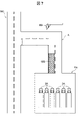
- FIG. 1 is a block diagram showing Embodiment 1 of a vehicle control device according to the present disclosure
- FIG. FIG. 2 is a schematic plan view showing an example of vehicle control by the vehicle control device of FIG. 1
- FIG. 2 is a flow chart showing the flow of processing by the vehicle control system of FIG. 1
- FIG. 2 is a plan view showing an example of restrictions on automatic driving of a vehicle by the vehicle control system of FIG. 1
- FIG. 3 is a schematic plan view showing a modification of the vehicle control of FIG. 2 by the vehicle control device of FIG. 1
- FIG. 2 is a block diagram showing Embodiment 2 of a vehicle control device according to the present disclosure
- FIG. 7 is a schematic plan view showing an example of vehicle control by the vehicle control device of FIG. 6
- FIG. 7 is a flowchart showing the flow of processing by the vehicle control device of FIG. 6;
- FIG. 1 is a block diagram showing Embodiment 1 of a vehicle control system according to the present disclosure.
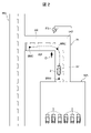
- FIG. 2 is a schematic plan view showing an example of vehicle control by the vehicle control device 1 of FIG.
- the vehicle control device 1 of the present embodiment is, for example, a device that controls automatic driving of the vehicle 2 by a vehicle control device 21 mounted on the vehicle 2 used for on-demand traffic and last one-mile mobility.
- the vehicle control device 1 is communicably connected to, for example, a plurality of vehicle control devices 21 mounted on a plurality of vehicles 2 and controls automatic driving of the plurality of vehicles 2 .
- the vehicle 2 controlled by the vehicle control device 1 includes, for example, a vehicle control device 21, a communication device 22, an in-vehicle external sensor 23, a vehicle sensor 24, a storage device 25, and a drive device 26.
- the vehicle control device 21 is, for example, an electronic control unit (ECU) that is mounted on the vehicle 2 and performs automatic operation of the vehicle 2 .
- Vehicle control device 21 is connected to communication device 22 , in-vehicle external sensor 23 , vehicle sensor 24 , storage device 25 and drive device 26 .
- Vehicle-mounted external sensor 23 is, for example, a sensor that detects objects around vehicle 2 .
- Vehicle-mounted external sensor 23 includes, for example, a monocular camera, a stereo camera, a laser radar, a millimeter wave radar, an ultrasonic sensor, an infrared sensor, and the like.
- Vehicle sensor 24 is, for example, a sensor that detects the state of vehicle 2 .
- the vehicle sensors 24 include, for example, wheel speed sensors, acceleration sensors, angular velocity sensors, global positioning system (GNSS) terminals, and the like.
- GNSS global positioning system
- the storage device 25 is, for example, a non-volatile memory mounted on the vehicle 2, and stores data including vehicle characteristics used for automatic driving of the vehicle 2, programs, and the like.
- the vehicle characteristics of the vehicle 2 used for automatic driving of the vehicle 2 may be stored in the non-volatile memory inside the vehicle control device 21 .
- the driving device 26 includes, for example, various actuators used for automatic driving of the vehicle 2, and a motor or engine that generates a driving force for causing the vehicle 2 to travel.
- the vehicle characteristics of the vehicle 2 used for automatic driving of the vehicle 2 by the vehicle control device 21 include various parameters of the vehicle 2, such as the tire diameter of the vehicle 2, cornering power, actuator responsiveness, and turning curvature radius. . Further, the vehicle characteristics may include, for example, the characteristics of the external world recognition function of the in-vehicle external sensor 23 mounted on the vehicle 2 and the characteristics of the position estimation function of the vehicle sensor 24 mounted on the vehicle 2 .
- the vehicle control device 1 can be composed of, for example, a computer, a server, or a computer system that includes a central processing unit (CPU), a storage device, a timer, and an input/output unit (not shown).
- CPU central processing unit
- storage device e.g., a hard disk drive
- timer e.g., a timer
- input/output unit not shown
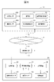
- the vehicle control device 1 includes, for example, a communication unit 11, a vehicle characteristic identification unit 12, an identification accuracy estimation unit 13, and an automatic driving control unit 14, as shown in FIG.
- the vehicle control device 1 may also include a database 15, for example.
- Each unit of the vehicle control device 1 shown in FIG. 1 is, for example, a functional block representing functions of the vehicle control device 1 realized by executing a program stored in a storage device by a CPU.
- the vehicle control device 1 may be composed of a plurality of devices installed at different locations, or may be provided by dividing each part shown in FIG. 1 into separate devices.
- part or all of the vehicle control device 1 may be, for example, a dedicated device, a general-purpose machine learning machine, a DSP (Digital Signal Processor), an FPGA (Field-Programmable Gate Array), a GPU (Graphics Processing Unit), a PLD ( It is also possible to replace it with a programmable logic device).
- the communication unit 11 is communicably connected to one or more vehicle control devices 21 mounted on one or more vehicles 2 . More specifically, the communication unit 11 is communicably connected to one or more vehicle control devices 21 via at least the wireless communication line 3 . In addition, the communication unit 11, for example, via a communication device 22 mounted on each vehicle 2, and a data communication network including a wireless communication line 3, a wireless base station 4, an Internet line 5, and a wired communication line 6 , may be communicably connected to one or more vehicle control devices 21 .
- the vehicle characteristic identification unit 12 acquires a control command value for automatic operation of the vehicle 2 by the vehicle control device 21 and the travel locus of the vehicle 2 via the communication unit 11, and identifies the vehicle used for automatic operation of the vehicle 2. Identify properties.
- the vehicle characteristic identification unit 12 identifies the vehicle characteristic of the vehicle 2 that has traveled through the predetermined identification area IA under the control of the vehicle control device 21, for example.
- the identification area IA is, for example, an area between a waiting area WA where one or more vehicles 2 are waiting and a mobility area MA where one or more vehicles 2 provide mobility services by automatic driving.
- the identification area IA includes, for example, a first straight portion IA1, a second straight portion IA2, and a curved portion IA3.
- the first straight portion IA1 is connected to the waiting area WA and extends straight.
- the second straight portion IA2 extends in a direction perpendicular to or crossing the first straight portion IA1 and is connected to the mobility area MA.
- a bent portion IA3 connects the first straight portion IA1 and the second straight portion IA2.
- the bent portion IA3 may be bent at a predetermined angle or may be smoothly curved.
- the identification area IA may be composed only of straight portions.
- one or more external sensors ES are installed in the identification area IA.
- the external sensor ES detects the position, attitude, movement direction, speed, etc. of the vehicle 2 traveling in the identification area IA.
- a monocular camera, a stereo camera, a laser radar, or a millimeter wave radar, for example, can be used as the external sensor ES.
- the communication unit 11 of the vehicle control device 1 is communicably connected to the external sensor ES installed in the identification area IA via, for example, the wireless communication line 3, the wireless base station 4, the Internet line 5, the wired communication line 6, and the like. It is In this case, the vehicle characteristic identification unit 12 of the vehicle control device 1 calculates the travel locus of the vehicle 2 based on the detection result of the vehicle 2 by the external sensor ES in the identification area IA acquired via the communication unit 11, for example.
- the reference route RP may be displayed in the identification area IA.
- the reference route RP is, for example, white lines including straight lines and curved lines drawn on the road surface of the identification area IA, and straight lines and curved lines projected on the road surface of the identification area IA by a projector.
- the vehicle characteristics identification unit 12 causes the vehicle control device 21 to cause the vehicle 2 to move along the reference route RP displayed in the identification area and detected by the in-vehicle external sensor 23. to identify the vehicle characteristics.
- the vehicle characteristic identification unit 12 acquires, for example, the detection result of an object D such as a dummy placed in the identification area IA by the in-vehicle external sensor 23 from the vehicle control device 21 via the communication device 22, and obtains the in-vehicle external world.
- the object detection function of the sensor 23 may be identified.
- the vehicle characteristic identification unit 12 may transmit, for example, the control command value in the identification area IA to the vehicle control device 21 via the communication unit 11, and cause the vehicle control device 21 to drive the vehicle 2 in the identification area IA. good.
- the identification accuracy estimation unit 13 estimates the identification accuracy of vehicle characteristics by the vehicle characteristics identification unit 12 . More specifically, the vehicle characteristic identification unit 12 identifies the vehicle characteristic of the vehicle 2 multiple times, for example. The identification accuracy estimator 13 estimates the accuracy of vehicle characteristic identification based on, for example, a plurality of identification results of vehicle characteristics obtained by a plurality of times of identification by the vehicle characteristic identifier 12 . More specifically, the identification accuracy estimator 13, for example, calculates a variance value from identification results of a plurality of vehicle characteristics, and uses the calculated variance value as the identification accuracy.
- the automatic driving control unit 14 controls automatic driving of the vehicle 2 based on the identification accuracy estimated by the identification accuracy estimation unit 13.
- the automatic driving control unit 14 transmits, for example, the vehicle characteristics whose identification accuracy estimated by the identification accuracy estimation unit 13 is higher than the threshold to the vehicle control device 21 via the communication unit 11, and the vehicle control device 21 Alternatively, the vehicle characteristics stored in the storage device 25 are updated.
- the automatic driving control unit 14 sets limits on automatic driving by the vehicle control device 21 according to the identification accuracy estimated by the identification accuracy estimation unit 13, for example. Further, the automatic driving control unit 14 preferentially operates the vehicle 2 with higher identification accuracy estimated by the identification accuracy estimation unit 13 among the plurality of vehicles 2, for example.
- the database 15 stores the vehicle characteristics identified by the vehicle characteristics identification unit 12 and the identification accuracy estimated by the identification accuracy estimation unit 13 .
- the database 15 is composed of non-volatile memory including, for example, ROM, flash memory, magnetic storage device, and the like.
- FIG. 3 is a flowchart showing the processing flow of the vehicle control device 1 of this embodiment and the vehicle control device 21 mounted on the vehicle 2.
- FIG. 3 the flow diagram on the left side shows the flow of processing P1 by the vehicle control device 1, and the flow diagram on the right side shows the flow of processing P2 by the vehicle control device 21 mounted on the vehicle 2.
- the vehicle control device 1 executes, for example, a process P101 of determining whether there is a request for a mobility service. More specifically, a mobility service user transmits a mobility service request to vehicle control device 1 through an application of an information terminal connected to Internet line 5, for example. The vehicle control device 1 receives the request for the mobility service via the communication unit 11 .
- the vehicle control device 1 determines whether or not there is a request for a mobility service by means of the automatic driving control unit 14. More specifically, when the communication unit 11 has not received a request for the mobility service, the automatic driving control unit 14 determines that there is no request (NO), and terminates the process P1 shown in FIG. On the other hand, when the communication unit 11 receives the request for the mobility service, the automatic driving control unit 14 determines that there is a request (YES), and executes the travel instruction process P102.
- the automatic driving control unit 14 of the vehicle control device 1 transmits a travel instruction to the vehicle control device 21 of the vehicle 2 via the communication unit 11, for example.
- the automatic driving control unit 14, for example refers to the identification accuracy of the plurality of vehicles 2 stored in the database 15, and among the plurality of vehicles 2 waiting in the waiting area WA shown in FIG.
- a traveling instruction is transmitted to a vehicle 2 with high accuracy to preferentially operate the vehicle.
- the vehicle control device 1 executes a process P103 of receiving vehicle characteristics of the vehicle 2, for example.
- the vehicle control device 21 transmits the vehicle characteristics of the vehicle 2 to the vehicle control device 1 via, for example, the communication device 22, the wireless communication line 3, the wireless base station 4, the Internet line 5, the wired communication line 6, and the like. to send.
- the vehicle control device 1 receives the vehicle characteristics of the vehicle 2 transmitted from the vehicle control device 21 via the communication unit 11 by the vehicle characteristics identification unit 12, for example, in the process P103 described above.
- the vehicle control device 1 may acquire the vehicle characteristics of the vehicle 2 stored in the database 15.
- the vehicle control device 21 which has finished transmitting the vehicle characteristics in the process P202 described above, controls the driving device 26 based on the detection results of the in-vehicle external sensor 23 and the vehicle sensor 24 to cause the vehicle 2 to run autonomously.
- An automatic driving process P203 for exiting from the waiting area WA is executed.
- the vehicle control device 21 executing the automatic driving process P203 executes a process P204 for determining whether or not the vehicle 2 has left the waiting area WA based on the detection results of the in-vehicle external sensor 23 and the vehicle sensor 24. do.
- the vehicle control device 21 determines that the vehicle 2 has not left the waiting area WA (NO), it continues the automatic driving process P203 and determines that the vehicle 2 has left the waiting area WA (YES). Then, the temporary stop process P205 is executed.
- the vehicle control device 21 controls the driving device 26 to stop the vehicle 2, and the vehicle 2 exits the waiting area WA and stops in the vehicle control device 1 via the communication device 22. send a stop signal to indicate that After that, the vehicle control device 21 executes time synchronization processing P206.
- the vehicle control device 1 acquires the vehicle characteristics of the vehicle 2 from the vehicle control device 21 or the database 15 in the process P103 described above, and then determines whether or not the vehicle 2 has exited the waiting area WA and stopped.
- Process P104 is executed.
- the vehicle control device 1 determines whether or not the automatic driving control unit 14 has received a stop signal from the vehicle control device 1 via the communication unit 11 , for example. For example, when the vehicle control device 1 determines that the automatic driving control unit 14 has not received the stop signal, it repeats this process P104, and when it determines that the automatic driving control unit 14 has received the stop signal (YES), time synchronization Process P105 is executed.
- the vehicle characteristic identification unit 12 of the vehicle control device 1 and the vehicle control device 21 of the vehicle 2 establish communication with each other and perform time synchronization. This clarifies the relationship between the time series of the control command value of the vehicle control device 21 and the time series of the travel locus of the vehicle 2 in the vehicle characteristic identification process, which will be described later, thereby facilitating identification of the vehicle characteristic.
- the vehicle control device 21 executes an automatic driving process P207 for autonomously driving the vehicle 2 in the identification area IA, and a process P208 for transmitting the control command value calculated in the process P207 to the vehicle control device 1. do.
- the vehicle control device 1 executes a process P106 in which the vehicle characteristic identification unit 12 receives the control command value transmitted from the vehicle control device 21 via the communication unit 11, for example.
- the control command values of the vehicle control device 21 include, for example, upper command values such as vehicle speed command value and steering angle command value, and lower command values such as throttle opening, brake pressure, and pinion angle.
- the vehicle control device 1 acquires the control command value of the vehicle control device 21 and the time at which the control command value was output, for example, in the process P106 described above. That is, the vehicle control device 1 acquires, for example, the time series of the control command values of the vehicle control device 21 in the process P106 described above.
- the vehicle control device 21 normally controls each part of the vehicle 2 such as the driving device 26 at regular intervals, so the control command value is also calculated at regular intervals. Therefore, the vehicle control device 1 periodically acquires the control command value for one cycle or several cycles from the vehicle control device 21, for example, in the process P106 described above. Further, the vehicle control device 1 acquires the control command value of the vehicle control device 21 when the vehicle 2 reaches, for example, a plurality of preset reference points BM1, BM2, BM3 in the identification area IA. may
- the vehicle control device 21 executes the above-described process P208 to generate the time series of the control command values from the reference point BM1 to the reference point BM2.
- the vehicle control device 1 receives the time series of control command values from the reference point BM1 to the reference point BM2 transmitted from the vehicle control device 21, for example, in the process P106 described above.
- the vehicle control device 21 receives, for example, the control command value in the identification area IA transmitted by the vehicle characteristic identification unit 12 of the vehicle control device 1 via the communication unit 11, and from the vehicle control device 1 in the automatic driving process P207.
- the received control command value may be used to autonomously drive the vehicle 2 .
- the vehicle control device 21 may cause the vehicle 2 to travel along the reference route RP displayed in the identification area IA and detected by the in-vehicle external sensor 23, for example, in the automatic driving process P207.
- the vehicle control device 21 determines whether or not the vehicle 2 has finished traveling in the identification area IA based on the detection results of the in-vehicle external sensor 23 and the vehicle sensor 24, for example, after the above-described processes P207 and P208. Then, the process P209 is executed. In this process P209, when the vehicle control device 21 determines that the vehicle 2 has not finished traveling in the identification area IA (NO), it repeats the above-described processes P207 and P208. On the other hand, when the vehicle control device 21 determines in this process P209 that the vehicle 2 has finished traveling in the identification area IA (YES), it executes a temporary stop process P210 to stop the vehicle 2 at the end of the identification area IA.
- the vehicle control device 1 executes the process P107 of acquiring the travel locus of the vehicle 2 after the process P106 of receiving the control command value described above.
- the vehicle characteristics identification unit 12 of the vehicle control device 1 receives the detection result of the vehicle 2 by the one or more external sensors ES installed in the identification area IA via the communication unit 11, for example, as described above. Then, based on the detection result, the travel locus of the vehicle 2 is acquired.
- the accuracy of estimating the travel locus can be improved.
- the vehicle control device 21 may cause the vehicle 2 to travel along the reference route RP displayed in the identification area IA and detected by the in-vehicle external sensor 23. be.
- the vehicle characteristic identification unit 12 of the vehicle control device 1 receives a control command value from the vehicle control device 21 that controls the vehicle 2 so that the vehicle 2 travels along the reference route RP in the above-described process P208. receive.
- the vehicle characteristic identification unit 12 may acquire the information of the reference route RP stored in advance in the database 15 as the travel locus of the vehicle 2, for example, in the process P107 described above.
- the vehicle control device 1 executes the process P108 of determining whether the vehicle 2 is approaching the end of the identification area IA.
- the vehicle characteristic identification unit 12 determines whether the vehicle 2 is located in the identification area IA based on the position information of the vehicle 2 calculated in the vehicle trajectory acquisition process P107 and the position information of the end of the identification area IA. is approaching the end of the
- the vehicle characteristics identification unit 12 calculates, for example, the distance from the vehicle 2 to the end of the identification area IA, and if the calculated distance is longer than a predetermined distance, It is determined that they are not approaching (NO). In this case, the vehicle characteristic identification unit 12 repeatedly executes the above-described processes P107 to P108. On the other hand, when the calculated distance is equal to or less than the predetermined distance, the vehicle characteristic identification unit 12 determines that the vehicle is approaching (YES), and executes processing P109 for determining whether or not the identification condition is satisfied. .
- the predetermined distance that serves as a threshold for determining whether or not the vehicle 2 is approaching the end of the identification area IA is not particularly limited. 2 is set to the distance at which the vehicle can safely stop at the end of the identification area IA. Specifically, this predetermined distance can be set to a distance of about 10 [m] to 30 [m], for example.
- the vehicle characteristic identification unit 12 determines whether the control command value of the vehicle control device 21 has been successfully received and whether the vehicle 2 is running. Check the success or failure of obtaining the trajectory. For example, when at least one of the control command value reception and the travel locus acquisition fails, the vehicle characteristic identification unit 12 determines that the identification condition is not met (NO), and terminates the process P1 shown in FIG. In this case, the vehicle control device 21 of the vehicle 2 ends the processing P2 shown in FIG. 3 without receiving the calculation result from the vehicle control device 1 in the calculation result reception processing P211.
- the vehicle characteristic identification unit 12 determines that the identification condition is established (YES) and executes the vehicle characteristic identification process P110, for example, when both the control command value and the travel locus are successfully received.
- the vehicle characteristic identification unit 12 uses the control command value for automatic driving by the vehicle control device 21 acquired in the process P106 described above and the travel locus of the vehicle 2 acquired in the process P107 described above to 2. Identify the vehicle characteristics used for automatic driving.
- the vehicle characteristic identification unit 12 detects, for example, the speed control command value, the position and time , the responsiveness of the vehicle speed control and the tire diameter of the vehicle 2 are identified. Further, the vehicle characteristic identification unit 12, for example, in a section in which the vehicle 2 is moving in the lateral direction at a constant speed, based on the steering angle control command value and the position and time information included in the travel locus. to identify cornering power and turning radius. It should be noted that the method for identifying the cornering power and the radius of curvature of turn can be a known method, so the description thereof will be omitted.
- the vehicle characteristic identification unit 12 may identify, for example, the object detection function of the in-vehicle external sensor 23 and the position detection function of the vehicle 2 of the vehicle sensor 24 .
- the vehicle characteristic identification unit 12 for example, in the process P106 described above, detects the object D installed in the identification area IA by the in-vehicle external sensor 23 and detects the position of the vehicle 2 by the vehicle sensor 24. Acquired from the control device 21 via the communication unit 11 . Further, the vehicle characteristic identification unit 12 acquires the absolute position of the object D recorded in advance in the non-volatile memory of the vehicle control device 1, for example.
- the vehicle characteristic identification unit 12 performs, for example, the absolute position of the object D, the position and time information included in the travel locus of the vehicle 2, and the detection result of the in-vehicle external sensor 23. , the object detection function of the in-vehicle external sensor 23 is identified. Further, the vehicle characteristic identification unit 12 determines the position of the vehicle 2 detected by the vehicle sensor 24 based on the position and time information included in the travel locus of the vehicle 2 and the detection result of the position of the vehicle 2 detected by the vehicle sensor 24, for example. Identify sensing functions.
- the vehicle control device 1 executes the identification accuracy estimation process P111.
- the identification accuracy estimation unit 13 of the vehicle control device 1 estimates the identification accuracy of the vehicle characteristics by the vehicle characteristics identification unit 12.
- FIG. More specifically, the identification accuracy estimator 13 calculates, as the identification accuracy, the variance value of the identification results of a plurality of vehicle characteristics obtained by a plurality of identifications by the vehicle characteristic identifier 12, for example, as described above. .
- the identification accuracy estimation unit 13 may calculate, for example, the object detection accuracy of the in-vehicle external sensor 23 and the position detection accuracy of the vehicle sensor 24.
- the identification accuracy estimating unit 13 for example, based on the absolute position of the object D, the position and time information included in the travel locus of the vehicle 2, and the detection result of the vehicle-mounted external sensor 23.
- the identification accuracy estimating unit 13 estimates the position detection accuracy of the vehicle sensor 24 based on, for example, position and time information included in the travel locus of the vehicle 2 and the detection result of the position of the vehicle 2 by the vehicle sensor 24. calculate.
- the vehicle control device 1 executes the operation management calculation process P112.
- the automatic driving control unit 14 of the vehicle control device 1 controls automatic driving of the vehicle 2 based on the vehicle characteristic identification accuracy estimated by the identification accuracy estimation unit 13 . More specifically, the automatic driving control unit 14 sets restrictions on the route to the destination based on the accuracy of identifying the vehicle characteristics of the vehicle 2, for example.
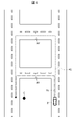
- FIG. 4 is a plan view showing an example of restrictions on automatic driving of the vehicle 2 set by the automatic driving control unit 14.
- the automatic driving control unit 14 sets restrictions on the road width on the route to the destination G based on the accuracy of identification of the vehicle characteristics of the vehicle 2, for example. More specifically, for example, the automatic driving control unit 14 limits the road width to the relatively narrow road width W1 for the vehicle 2 whose vehicle characteristics identification accuracy is equal to or higher than a predetermined threshold value. set. In addition, for example, the automatic driving control unit 14 sets the road width limit to a relatively wide road width W2 for the vehicle 2 whose vehicle characteristic identification accuracy is lower than a predetermined threshold value.
- the vehicle control device 1 can control the automatic driving of the vehicle 2 so that the vehicle 2 with high vehicle characteristic identification accuracy travels along the shortest route R1 to the destination G including the narrow road width W1. can.
- the vehicle control device 1 automatically controls the vehicle 2 so that the vehicle 2 with low vehicle characteristic identification accuracy avoids the route R1 including the narrow road width W1 and travels along the route R2 with the wider road width W2. You can control your driving.
- the automatic driving control unit 14 calculates the optimal routes R1 and R2 for each vehicle 2 based on the restrictions set according to the identification accuracy of the vehicle characteristics of the vehicle 2 in the operation management calculation process P112 described above. You may do so.
- the automatic driving control unit 14 may change the destination according to the identification accuracy of the vehicle characteristics. For example, the vehicle 2 whose vehicle characteristic identification accuracy is low is difficult to automatically drive in units of several centimeters. Therefore, for example, when sufficient space cannot be secured around the destination, the automatic driving control unit 14 sets a point with a wider space around it as a new destination.
- the vehicle control device 1 executes the calculation result transmission process P113.
- the vehicle characteristic identification unit 12 of the vehicle control device 1 transmits the identified vehicle characteristics of the vehicle 2 and the estimated identification accuracy to the vehicle control device 21 of the vehicle 2 via the communication unit 11, for example.
- the vehicle control device 21 of the vehicle 2 executes a process P211 of receiving the vehicle characteristics and identification accuracy transmitted from the vehicle control device 1 via the communication device 22, for example.
- the vehicle control device 1 may transmit the target route calculated according to the identification accuracy of the vehicle 2 to the vehicle control device 21 of the vehicle 2 in the process P113 described above.
- the automatic driving control unit 14 transmits the vehicle characteristics whose identification accuracy estimated by the identification accuracy estimation unit 13 is higher than the threshold value to the vehicle control device 21 via the communication unit 11, for example, in the above-described process P113. You may In this case, the vehicle characteristics stored in the vehicle control device 21 may be updated in the process P211 described above. After completing these processes P113 and P211, the vehicle control device 1 and the vehicle control device 21 of the vehicle 2 end the processes P1 and P2 shown in FIG. After that, the vehicle 2 starts automatic driving in the mobility area MA under the control of the vehicle control device 21 to provide mobility services such as on-demand transportation and last-mile mobility.
- the vehicle 2 passes through the identification area IA and returns to the waiting area WA under the control of the vehicle control device 21 .
- the vehicle control device 1 and the vehicle control device 21 of the vehicle 2 may execute the above-described processes P1 and P2. Further, the vehicle control device 1 communicates with the vehicle control device 21 of the vehicle 2 that has returned to the waiting area WA, for example, and transmits the newly identified vehicle characteristics and the identification accuracy from the vehicle control device 1 to the vehicle control device 21. can be sent to Further, the vehicle control device 1 may store the newly identified vehicle characteristics and the identification accuracy in the database 15, for example.
- the vehicle control device 1 receives the vehicle characteristics from the vehicle 2 in the process P103 before the vehicle 2 enters the identification area IA.
- the vehicle characteristics of the vehicle 2 may be obtained later.
- the vehicle control device 1 for example, in the process P105 described above, checks whether the vehicle characteristics of the vehicle 2 have been acquired. , or obtain vehicle characteristics stored in the database 15 . After that, the vehicle control device 1 can execute the aforementioned process P106.
- the vehicle control device 1 of this embodiment is a device that controls automatic driving of the vehicle 2 by a vehicle control device 21 mounted on the vehicle 2 .
- the vehicle control device 1 acquires a control command value for automatic operation and a travel locus of the vehicle 2 from the vehicle control device 21 via a communication unit 11 communicably connected to the vehicle control device 21 and the communication unit 11 . and a vehicle characteristic identification unit 12 that identifies vehicle characteristics used for automatic driving.
- the vehicle control device 1 also includes an identification accuracy estimating unit 13 for estimating the accuracy of vehicle characteristic identification by the vehicle characteristic identifying unit 12, and automatic driving of the vehicle 2 based on the identification accuracy estimated by the identification accuracy estimating unit 13. and an automatic operation control unit 14 for controlling.
- the vehicle control device 1 of the present embodiment can improve the tracking accuracy of the vehicle 2 with respect to the target route, and can improve the operating rate of the vehicle 2 in on-demand traffic and last one mile mobility.
- the vehicle characteristics which are parameters used for automatic driving of the vehicle 2 by the vehicle control device 21
- the vehicle characteristics can be updated at any time, and changes in the vehicle characteristics over time can be reflected in the automatic driving of the vehicle 2 .
- the feedforward term rather than the feedback term
- the vehicle control device 1 of the present embodiment by identifying the vehicle characteristics of the vehicle 2 and estimating the identification accuracy, the position detection accuracy of the vehicle sensor 24 mounted on the vehicle 2 may be decreased or over time. It is possible to detect a decrease in tracking accuracy due to a change in vehicle characteristics. For this reason, the vehicle control device 1 of the present embodiment, for example, when there is a request for a service from a user of a mobility service, the vehicle control device 1 selects the vehicles 2 waiting in the waiting area WA from among a plurality of vehicles 2 with accuracy of identification of vehicle characteristics. A vehicle 2 with a higher value can be selected and operated preferentially. As a result, the tracking accuracy of the target route by the vehicle 2 that provides the mobility service is improved, and the operating rate of the entire mobility service provided by the plurality of vehicles 2 can be improved.
- the vehicle control device 1 of the present embodiment it is possible to select and operate a vehicle 2 having a vehicle characteristic identification accuracy that meets the service request of the user of the mobility service. More specifically, for example, it is assumed that the mobility area MA where the mobility service by the vehicle 2 is provided is left-hand traffic. In this case, if the route to the destination based on the service request consists only of going straight and turning left, the target route following accuracy required of the vehicle 2 is relatively low. On the other hand, when the route to the destination includes narrow roads and right turns, the vehicle 2 is required to follow a target route with relatively high accuracy. As described above, according to the vehicle control system 1 of the present embodiment, by selecting and operating the vehicle 2 having the vehicle characteristic identification accuracy corresponding to the required tracking accuracy of the target route, a plurality of vehicles 2 can The operational availability of the entire mobility service provided can be improved.
- the vehicle characteristic identification unit 12 identifies the vehicle characteristics of the vehicle 2 that has traveled through the predetermined identification area IA under the control of the vehicle control device 21 .
- the vehicle control device 1 of the present embodiment allows the vehicle 2 traveling in the identification area IA by automatic driving under the control of the vehicle control device 21 to go straight, accelerate, decelerate, turn, turn, turn right or left. For example, it is possible to perform a desired operation according to the shape of the identification area IA. Therefore, according to the vehicle control device 1 of the present embodiment, it is possible to improve the accuracy of identifying the vehicle characteristics of the vehicle 2 .
- the communication unit 11 is communicably connected to the external sensor ES installed in the identification area IA.
- the vehicle characteristic identification unit 12 also calculates the travel locus of the vehicle 2 based on the detection result of the vehicle 2 by the external sensor ES acquired via the communication unit 11 .
- the vehicle control device 1 can accurately calculate the travel locus of the vehicle 2 traveling in the identification area IA regardless of the position detection accuracy of the vehicle sensor 24 mounted on the vehicle 2. .
- the vehicle control device 21 mounted on the vehicle 2 is connected to the onboard external sensor 23 mounted on the vehicle 2 . Further, in the vehicle control device 1 of the present embodiment, the vehicle characteristics identification unit 12 acquires the detection result of the object D installed in the identification area IA by the vehicle-mounted external sensor 23 from the vehicle control device 21 via the communication unit 11. Then, the object detection function of the in-vehicle external sensor 23 is identified. With such a configuration, the vehicle control device 1 of the present embodiment can identify the detection characteristics of the in-vehicle external sensor 23 mounted on the vehicle 2 as the vehicle characteristics of the vehicle 2 .
- the vehicle characteristics identification unit 12 transmits the control command value in the identification area IA to the vehicle control device 21 via the communication unit 11, and the vehicle control device 21 controls the vehicle 2. Run in the identification area IA.
- the vehicle control device 1 of the present embodiment determines the vehicle characteristics of the vehicle 2 based on the control command value transmitted to the vehicle control device 21 and the travel locus of the vehicle 2 traveling in the identification area IA. It becomes possible to identify and estimate the accuracy of the identification.
- the vehicle control device 21 mounted on the vehicle 2 is connected to the vehicle-mounted external sensor 23 mounted on the vehicle 2 .
- the vehicle characteristic identification unit 12 causes the vehicle 2 to travel along the reference route RP displayed in the identification area IA and detected by the vehicle-mounted external sensor 23 by the vehicle control device 21. to identify the vehicle characteristics.
- the vehicle control device 1 of the present embodiment can use the control command value of the vehicle control device 21 and the reference as the travel locus of the vehicle 2 without using the external sensor ES installed in the identification area IA.
- Vehicle characteristics of the vehicle 2 can be identified based on the route RP.
- the reference route RP includes a straight line and a curved line, it is possible to identify the vehicle characteristics of the vehicle 2 in the longitudinal direction and the lateral direction, thereby improving the tracking accuracy of the vehicle 2 with respect to the target route.
- the automatic driving control unit 14 transmits the vehicle characteristics whose identification accuracy estimated by the identification accuracy estimation unit 13 is higher than the threshold value to the vehicle control device 1 via the communication unit 11. 21 to update the vehicle characteristics stored in the vehicle control device 21 .
- the automatic driving control unit 14 sets limits on automatic driving by the vehicle control device 21 according to the identification accuracy estimated by the identification accuracy estimation unit 13.
- the vehicle control device 1 of the present embodiment can improve the safety of automatic driving of the vehicle 2 and perform optimal control according to the accuracy of identifying the vehicle characteristics of the vehicle 2. It is possible to improve the operating rate of the entire mobility service provided by the plurality of vehicles 2 .
- the automatic driving control unit 14 preferentially operates a vehicle with higher identification accuracy estimated by the identification accuracy estimation unit 13 among the plurality of vehicles 2 .
- the tracking accuracy of the target route by the vehicle 2 that provides the mobility service is improved, and the operating rate of the entire mobility service provided by the plurality of vehicles 2 is improved. can be improved.
- the vehicle control device 1 of this embodiment also includes a database 15 that stores the vehicle characteristics of the vehicle 2 and their identification accuracy.
- the vehicle control device 1 can use the vehicle characteristics and the identification accuracy of the vehicles 2 stored in the database 15, and can calculate the operating rate of the entire mobility service provided by the plurality of vehicles 2. can be improved.
- the vehicle control apparatus 1 capable of improving the tracking accuracy of the vehicle 2 with respect to the target route, and the entire mobility service provided by the plurality of vehicles 2 can be provided. operation rate can be improved.
- the vehicle control apparatus 1 of this embodiment is not limited to the configuration described above. A modification of the vehicle control system 1 of the present embodiment will be described below with reference to FIG.
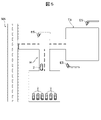
- FIG. 5 is a schematic plan view showing a modification of the vehicle control of FIG. 2 by the vehicle control device 1 of FIG.
- the vehicle characteristics identification unit 12 of the vehicle control device 1 identifies the vehicle characteristics of the vehicle 2 that has traveled in the maintenance area TA, which is wider than the identification area IA, under the control of the vehicle control device 21 .
- the maintenance area TA has an area and shape that allow the vehicle 2 to turn with a larger turning radius than the vehicle 2 turns in the identification area IA, and to allow the vehicle 2 to run in a slalom.
- the vehicle control device 1 identifies the vehicle characteristics of the vehicle 2 in the identification area IA each time the vehicle 2 travels through the mobility area MA, while the vehicle control device 1 identifies the vehicle characteristics of the vehicle 2 in the maintenance area TA. It is performed in a predetermined cycle such as a month or several months. According to the vehicle control device 1 according to this modified example, the vehicle characteristics of the vehicle 2 can be identified more comprehensively, and the accuracy of identifying the vehicle characteristics can be improved.
- the vehicle control device 1 According to the vehicle control device 1 according to this modification, the tracking accuracy of the target route by the vehicle 2 that provides the mobility service is further improved, and the operating rate of the entire mobility service provided by the plurality of vehicles 2 is improved. can be improved.
- FIG. 6 is a block diagram showing Embodiment 2 of the vehicle control device according to the present disclosure.
- FIG. 7 is a schematic plan view illustrating processing by the vehicle control device 1A of FIG.
- the vehicle control device 1 that controls the automatic driving of the vehicle 2 by the vehicle control device 21 mounted on the vehicle 2 used for on-demand transportation and last-mile mobility has been described.
- a vehicle control device 1A that controls automatic driving of a vehicle 2A such as a large truck that loads and unloads cargo will be described.
- the same components as those of the vehicle control device 1, the vehicle 2, and the identification area IA of the above-described first embodiment are given the same reference numerals as those of the first embodiment, and description thereof will be omitted.
- the vehicle control device 1A of this embodiment includes, for example, an external sensor ES and a weight sensor WS installed in the identification area IA.
- the communication unit 11, the vehicle characteristic identification unit 12, the identification accuracy estimation unit 13, and the automatic driving control unit 14 are, like the vehicle control device 1 of the first embodiment described above, one or more computers and servers. , or configured by a computer system.
- the external sensor ES and the weight sensor WS are communicably connected to the communication unit 11, the vehicle characteristic identification unit 12, the identification accuracy estimation unit 13, and the automatic driving control unit 14.
- the vehicle 2A loads and unloads cargo in a loading and unloading area PA such as a truck yard, distribution center, and warehouse. After loading and unloading the cargo in the loading and unloading area PA, the vehicle 2A moves from the loading and unloading area PA to the loading and unloading area of the mobility area MA by automatic operation under the control of the vehicle control device 21. to run.
- a loading and unloading area PA such as a truck yard, distribution center, and warehouse.
- the vehicle control device 1A measures the weight of the vehicle 2A with the weight sensor WS.
- the vehicle control device 1A may measure, for example, not only the weight of the entire vehicle 2A but also the load acting on each wheel of the vehicle 2A.
- the vehicle control device 1A of this embodiment uses the weight of the vehicle 2A measured by the weight sensor WS in the identification area IA and the load acting on each wheel to identify the vehicle characteristics of the vehicle 2A. As a result, even when the weight of the vehicle 2A and the load acting on each wheel change due to the loading and unloading of cargo, the vehicle characteristics of the vehicle 2A can be identified with high accuracy, and the accuracy of following the target route of the vehicle 2A can be improved. be able to.
- the vehicle 2A travels in the identification area IA, and the vehicle control device 1A receives a control command value from the vehicle control device 21 of the vehicle 2A. Further, the vehicle characteristic identification unit 12 of the vehicle control device 1A receives the detection result of the vehicle 2A by the external sensor ES installed in the identification area IA, and acquires the travel locus of the vehicle 2A. The vehicle characteristic identification unit 12 also identifies the vehicle characteristic of the vehicle 2A based on the received control command value and the acquired travel locus.
- the identification accuracy estimating unit 13 of the vehicle control device 1A estimates the identification accuracy of the vehicle characteristics by the vehicle characteristics identifying unit 12, as in the first embodiment described above. Further, the automatic driving control unit 14 of the vehicle control device 1A calculates, for example, the travel route of the vehicle 2A based on the identification accuracy estimated by the identification accuracy estimation unit 13, and calculates the vehicle characteristic and its identification accuracy. Send to the control device 21 . Thereby, the vehicle control device 1A controls automatic driving of the vehicle 2A. After that, the vehicle 2A automatically operates in the mobility area MA and moves to a loading/unloading area in the mobility area MA.
- the communication unit 11 is communicably connected to the weight sensor WS installed in the identification area IA. Further, the vehicle characteristic identification unit 12 identifies vehicle characteristics based on the detection result of the weight of the vehicle 2A obtained by the weight sensor WS through the communication unit 11 .
- the weight sensor WS is used to identify the vehicle characteristics of the vehicle 2A after loading and unloading of cargo. It is possible to improve the tracking accuracy with respect to the target route. As a result, in the loading/unloading area of the mobility area MA, it is possible to prevent errors from occurring in the stop position and angle of the vehicle 2A, and to efficiently load and unload the cargo.
- the vehicle 2A is a towing vehicle
- only the trailer head is allowed to travel in the identification area IA while the trailer is being loaded and unloaded, and the vehicle characteristics are identified by the vehicle characteristics identification unit 12 of the vehicle control device 1A. may be performed. After loading and unloading the cargo on the trailer, the trailer and the trailer head are connected to travel the identification area IA, and the vehicle characteristics can be similarly identified by the vehicle characteristics identification unit 12 of the vehicle control device 1A.
- the vehicle control device 1A of the present embodiment may, for example, identify the vehicle characteristics of the vehicle 2A and estimate the identification accuracy each time the vehicle 2A loads and unloads cargo in the mobility area MA.
- the processing of the vehicle control device 1A and the vehicle control device 21 of the vehicle 2A in this case will be described with reference to FIG.
- FIG. 8 is a flowchart showing the flow of processing by the vehicle control device 1A of FIG. 6 and the vehicle control device 21 of the vehicle 2A.
- the vehicle control device 1A and the vehicle control device 21 of the vehicle 2A start processes P1A and P2A shown in FIG. 8, respectively.
- the vehicle control device 21 of the vehicle 2A first executes a process P201A for determining whether or not cargo has been unloaded.
- the vehicle 2A travels along a predetermined travel route and loads and unloads cargo in a predetermined loading/unloading area, for example, during automatic operation under the control of the vehicle control device 21 .
- the vehicle control device 21 of the vehicle 2A can determine whether or not there is loading/unloading based on the position information of the vehicle 2A, for example.
- the vehicle control device 21 of the vehicle 2A determines that no cargo has been unloaded (NO)
- processing P202A for transmitting vehicle characteristics is executed.
- This process 202A is the same as the process P202 in the first embodiment shown in FIG.
- the vehicle control device 1A first executes the processing P101A for receiving the vehicle characteristics from the vehicle control device 21 of the vehicle 2A, and then determines whether or not the vehicle characteristics have been received. Then, the process P102A is executed. When the vehicle characteristic is not received in process P101A, the vehicle control device 1A determines that the vehicle characteristic is not received (NO) in process P102A, and terminates process P1A shown in FIG.
- process P101A determines that they have been received (YES) in process P102A.
- the vehicle control device 1A and the vehicle control device 21 of the vehicle 2A execute the time synchronization processes P103A and P203A, respectively.
- These processes P103A and P203A are similar to the processes P105 and P206 of the first embodiment shown in FIG.
- the vehicle control device 21 of the vehicle 2A executes an automatic driving process P204A in the mobility area MA and an automatic driving information transmission process P205A, and executes a process P206A for determining whether the vehicle 2A has traveled a predetermined distance. do.
- the vehicle control device 21 determines that the vehicle has not traveled the predetermined distance (NO)
- the vehicle control device 1A executes processing P104A for periodically receiving automatic driving information transmitted from the vehicle control device 21 of the vehicle 2A.
- This automatic driving information includes output results of automatic driving functions such as control command values for automatic driving of the vehicle 2A by the vehicle control device 21 and position information of the vehicle 2A, for example.
- the vehicle control device 1A executes the process P105A for determining whether or not the predetermined time has passed. If it is determined that it is not (NO), the above-described process P104A is repeated.
- the vehicle control apparatus 1A determines that the predetermined time has passed (YES) in the process P105A described above, the vehicle characteristic identification process P106A similar to the processes P110 and P111 in the first embodiment shown in FIG. An identification accuracy estimation process P107A is executed. After that, the vehicle control device 1A executes the vehicle characteristic transmission process P108A, and transmits the vehicle characteristics of the vehicle 2A and the identification accuracy obtained in the above-described processes P106A and P107A to the vehicle control device 21 of the vehicle 2A.
- the vehicle control device 21 of the vehicle 2A determines in the aforementioned process P206A that the vehicle 2A has traveled the predetermined distance (YES)
- the vehicle control device 21 receives the vehicle characteristics and their identification accuracy transmitted from the vehicle control device 1A. Execute P207A.
- the vehicle control device 21 of the vehicle 2A executes the processing P208A for determining whether the vehicle 2A is stopped, and when determining that the vehicle 2A is running (NO), the vehicle 2A is automatically driven. Continuously, this process P208A is repeated.
- the vehicle control device 21 of the vehicle 2A executes the vehicle characteristic update process P209A when the vehicle 2A is temporarily stopped and determines that the vehicle is currently stopped (YES) in this process P208A.
- the vehicle control device 21 replaces the vehicle characteristics and their identification accuracy stored in the memory or storage device 25 of the vehicle control device 21 with the vehicle characteristics and their identification accuracy of the vehicle 2A received in the aforementioned process P207. and store it.
- 1 vehicle control device 11 communication unit, 12 vehicle characteristic identification unit, 13 identification accuracy estimation unit, 14 automatic operation control unit, 15 database, 2 vehicle, 2A vehicle, 21 vehicle control device, 23 in-vehicle external sensor, D object, ES external sensor, IA identification area, RP reference path, TA maintenance area, WS weight sensor.
Landscapes
- Engineering & Computer Science (AREA)
- Mechanical Engineering (AREA)
- Automation & Control Theory (AREA)
- Transportation (AREA)
- General Physics & Mathematics (AREA)
- Physics & Mathematics (AREA)
- Computing Systems (AREA)
- Human Computer Interaction (AREA)
- Theoretical Computer Science (AREA)
- Multimedia (AREA)
- Operations Research (AREA)
- Business, Economics & Management (AREA)
- Accounting & Taxation (AREA)
- Development Economics (AREA)
- Economics (AREA)
- General Business, Economics & Management (AREA)
- Traffic Control Systems (AREA)
Abstract
Description
図1は、本開示に係る車両管制装置の実施形態1を示すブロック図である。図2は、図1の車両管制装置1による車両管制の一例を示す模式的な平面図である。本実施形態の車両管制装置1は、たとえば、オンデマンド交通やラストワンマイルモビリティに使用される車両2に搭載された車両制御装置21による車両2の自動運転を管制する装置である。車両管制装置1は、たとえば、複数の車両2に搭載された複数の車両制御装置21と通信可能に接続され、複数の車両2の自動運転を管制する。
以下、図6から図8を参照して、本開示に係る車両管制装置の実施形態2を説明する。図6は、本開示に係る車両管制装置の実施形態2を示すブロック図である。図7は、図6の車両管制装置1Aによる処理を説明する模式的な平面図である。
13 同定精度推定部、14 自動運転管制部、15 データベース、
2 車両、2A 車両、21 車両制御装置、23 車載外界センサ、
D 物体、ES 外界センサ、IA 同定エリア、RP 参照経路、
TA メンテナンスエリア、WS 重量センサ。
Claims (12)
- 車両に搭載された車両制御装置による前記車両の自動運転を管制する車両管制装置であって、
前記車両制御装置と通信可能に接続される通信部と、
前記通信部を介して前記車両制御装置から自動運転の制御指令値と前記車両の走行軌跡とを取得して自動運転に用いられる車両特性を同定する車両特性同定部と、
前記車両特性同定部による前記車両特性の同定精度を推定する同定精度推定部と、
前記同定精度推定部によって推定された前記同定精度に基づいて前記車両の自動運転を管制する自動運転管制部と、
を備えることを特徴とする車両管制装置。 - 前記車両特性同定部は、前記車両制御装置の制御により所定の同定エリアを走行した前記車両の前記車両特性を同定することを特徴とする請求項1に記載の車両管制装置。
- 前記通信部は、前記同定エリアに設置された外界センサと通信可能に接続され、
前記車両特性同定部は、前記通信部を介して取得した前記外界センサによる前記車両の検出結果に基づいて前記車両の走行軌跡を算出することを特徴とする請求項2に記載の車両管制装置。 - 前記通信部は、前記同定エリアに設置された重量センサと通信可能に接続され、
前記車両特性同定部は、前記通信部を介して取得した前記重量センサによる前記車両の重量の検出結果に基づいて前記車両特性を同定することを特徴とする請求項2に記載の車両管制装置。 - 前記車両制御装置は、前記車両に搭載された車載外界センサに接続され、
前記車両特性同定部は、前記同定エリアに設置された物体の前記車載外界センサによる検知結果を前記車両制御装置から前記通信部を介して取得して、前記車載外界センサによる物体検知機能を同定することを特徴とする請求項2に記載の車両管制装置。 - 前記車両特性同定部は、前記通信部を介して前記同定エリアにおける制御指令値を前記車両制御装置へ送信して、前記車両制御装置によって前記車両を前記同定エリアで走行させることを特徴とする請求項2に記載の車両管制装置。
- 前記車両制御装置は、前記車両に搭載された車載外界センサに接続され、
前記車両特性同定部は、前記車両制御装置により、前記同定エリアに表示されて前記車載外界センサによって検出された参照経路に沿って前記車両を走行させ、前記車両特性を同定することを特徴とする請求項2に記載の車両管制装置。 - 前記自動運転管制部は、前記同定精度推定部によって推定された前記同定精度がしきい値よりも高い前記車両特性を、前記通信部を介して前記車両制御装置へ送信して前記車両制御装置に格納された前記車両特性を更新することを特徴とする請求項1に記載の車両管制装置。
- 前記自動運転管制部は、前記同定精度推定部によって推定された前記同定精度に応じて前記車両制御装置による前記自動運転の制限を設定することを特徴とする請求項1に記載の車両管制装置。
- 前記自動運転管制部は、複数の前記車両のうち前記同定精度推定部によって推定された前記同定精度がより高い前記車両を優先的に運行させることを特徴とする請求項1に記載の車両管制装置。
- 前記車両特性および前記同定精度を格納するデータベースを備えることを特徴とする請求項1に記載の車両管制装置。
- 前記車両特性同定部は、前記車両制御装置の制御により前記同定エリアよりも広いメンテナンスエリアを走行した前記車両の前記車両特性を同定することを特徴とする請求項2に記載の車両管制装置。
Priority Applications (1)
| Application Number | Priority Date | Filing Date | Title |
|---|---|---|---|
| US18/551,673 US12391237B2 (en) | 2021-04-16 | 2022-03-04 | Vehicle supervision device |
Applications Claiming Priority (2)
| Application Number | Priority Date | Filing Date | Title |
|---|---|---|---|
| JP2021069894A JP7621168B2 (ja) | 2021-04-16 | 2021-04-16 | 車両管制装置 |
| JP2021-069894 | 2021-04-16 |
Publications (1)
| Publication Number | Publication Date |
|---|---|
| WO2022219962A1 true WO2022219962A1 (ja) | 2022-10-20 |
Family
ID=83640318
Family Applications (1)
| Application Number | Title | Priority Date | Filing Date |
|---|---|---|---|
| PCT/JP2022/009352 Ceased WO2022219962A1 (ja) | 2021-04-16 | 2022-03-04 | 車両管制装置 |
Country Status (3)
| Country | Link |
|---|---|
| US (1) | US12391237B2 (ja) |
| JP (1) | JP7621168B2 (ja) |
| WO (1) | WO2022219962A1 (ja) |
Citations (3)
| Publication number | Priority date | Publication date | Assignee | Title |
|---|---|---|---|---|
| JP2020060553A (ja) * | 2018-10-12 | 2020-04-16 | バイドゥ ユーエスエイ エルエルシーBaidu USA LLC | 自動運転のための事前収集の静的反射図に基づく自動lidarキャリブレーション |
| WO2021033632A1 (ja) * | 2019-08-20 | 2021-02-25 | 日立オートモティブシステムズ株式会社 | 車両制御方法及び車両制御装置 |
| JP2022031125A (ja) * | 2020-08-06 | 2022-02-18 | 株式会社デンソー | 車両管理装置、車両管理方法、車両管理プログラム |
Family Cites Families (7)
| Publication number | Priority date | Publication date | Assignee | Title |
|---|---|---|---|---|
| US9274525B1 (en) * | 2012-09-28 | 2016-03-01 | Google Inc. | Detecting sensor degradation by actively controlling an autonomous vehicle |
| WO2019077739A1 (ja) | 2017-10-20 | 2019-04-25 | 株式会社日立製作所 | 移動体制御システム |
| JP7192309B2 (ja) | 2018-08-28 | 2022-12-20 | 株式会社アイシン | 車両制御装置、および車両制御方法 |
| CN109345596B (zh) * | 2018-09-19 | 2024-07-12 | 阿波罗智能技术(北京)有限公司 | 多传感器标定方法、装置、计算机设备、介质和车辆 |
| JP2020149334A (ja) | 2019-03-13 | 2020-09-17 | 株式会社デンソーテン | 駐車制御装置、車載装置、駐車システムおよび駐車制御方法 |
| JP2022112971A (ja) * | 2021-01-22 | 2022-08-03 | 株式会社デンソー | 車両制御装置、車両制御方法および車両制御プログラム |
| JP7363831B2 (ja) * | 2021-02-10 | 2023-10-18 | 株式会社デンソー | 情報収集制御装置、情報収集制御方法、情報収集制御プログラム |
-
2021
- 2021-04-16 JP JP2021069894A patent/JP7621168B2/ja active Active
-
2022
- 2022-03-04 US US18/551,673 patent/US12391237B2/en active Active
- 2022-03-04 WO PCT/JP2022/009352 patent/WO2022219962A1/ja not_active Ceased
Patent Citations (3)
| Publication number | Priority date | Publication date | Assignee | Title |
|---|---|---|---|---|
| JP2020060553A (ja) * | 2018-10-12 | 2020-04-16 | バイドゥ ユーエスエイ エルエルシーBaidu USA LLC | 自動運転のための事前収集の静的反射図に基づく自動lidarキャリブレーション |
| WO2021033632A1 (ja) * | 2019-08-20 | 2021-02-25 | 日立オートモティブシステムズ株式会社 | 車両制御方法及び車両制御装置 |
| JP2022031125A (ja) * | 2020-08-06 | 2022-02-18 | 株式会社デンソー | 車両管理装置、車両管理方法、車両管理プログラム |
Also Published As
| Publication number | Publication date |
|---|---|
| JP2022164417A (ja) | 2022-10-27 |
| JP7621168B2 (ja) | 2025-01-24 |
| US20240166195A1 (en) | 2024-05-23 |
| US12391237B2 (en) | 2025-08-19 |
Similar Documents
| Publication | Publication Date | Title |
|---|---|---|
| CN116080794B (zh) | 自主完成自身组装的已部分组装的车辆及车辆的制造方法 | |
| EP3782000B1 (en) | A method for controlling a string of vehicles | |
| CN114761300B (zh) | 驾驶控制方法及驾驶控制装置 | |
| CN112099483B (zh) | 监控自动驾驶车辆中的定位功能的方法 | |
| CN114620068B (zh) | 自动驾驶系统的物理信息优化 | |
| US20190118829A1 (en) | Systems and Methods for a Vehicle Controller Robust to Time Delays | |
| CN113044058B (zh) | 自动驾驶车辆三点转弯 | |
| CN112477849A (zh) | 自动驾驶卡车的泊车控制方法、装置及自动驾驶卡车 | |
| JP7172973B2 (ja) | 自動駐車システム | |
| CN112230645B (zh) | 用于控制无人驾驶车辆的操纵杆控制的安全机制 | |
| CN111222728A (zh) | 无人驾驶运载车辆调度方法、调度系统及存储介质 | |
| US11958506B2 (en) | Vehicle control device and vehicle control method | |
| CN118170131A (zh) | 自动驾驶控制装置 | |
| CN112406859A (zh) | 用于车辆运动规划和控制算法的方法和控制设备 | |
| JP7380662B2 (ja) | 自動駐車システム及び自動駐車システムの制御方法 | |
| JP7468552B2 (ja) | 車両管理装置、及び車両管理方法 | |
| JP2024118103A (ja) | 路面状態取得システム | |
| JP2024081086A (ja) | 駐車支援装置 | |
| JP7621168B2 (ja) | 車両管制装置 | |
| US20250162601A1 (en) | Estimation of driver interaction based tuning parameters for automated driving or driver assistance | |
| AU2020343829A1 (en) | Waypoint information transmission method, apparatus and system for platooning | |
| JP2025038999A (ja) | 状態切替装置、移動体、および移動体の製造方法 | |
| JP7337211B1 (ja) | 走行車線判定装置 | |
| JP7816047B2 (ja) | 評価システム、制御装置、評価方法、評価プログラム | |
| US12291207B2 (en) | Driver assistance for high accelleration and speed on a minimum time path |
Legal Events
| Date | Code | Title | Description |
|---|---|---|---|
| 121 | Ep: the epo has been informed by wipo that ep was designated in this application |
Ref document number: 22787890 Country of ref document: EP Kind code of ref document: A1 |
|
| WWE | Wipo information: entry into national phase |
Ref document number: 18551673 Country of ref document: US |
|
| NENP | Non-entry into the national phase |
Ref country code: DE |
|
| 122 | Ep: pct application non-entry in european phase |
Ref document number: 22787890 Country of ref document: EP Kind code of ref document: A1 |
|
| WWG | Wipo information: grant in national office |
Ref document number: 18551673 Country of ref document: US |